det-654 guide to low voltage system design and selectivity · guide to low voltage system design...
TRANSCRIPT

Guide to Low Voltage SystemDesign and Selectivity
OpensUnaffected
imagination at work

Contents
Foreword . . . . . . . . . . . . . . . . . . . . . . . . . . . . . . . . . . . . . . . . . . . . . . . . . . . . . . . . . . . . . . . . . . . . . . . . . . . . . . . . . . . . . . . . .1Introduction . . . . . . . . . . . . . . . . . . . . . . . . . . . . . . . . . . . . . . . . . . . . . . . . . . . . . . . . . . . . . . . . . . . . . . . . . . . . . . . . . . . . . .2National Electric Code Requirements . . . . . . . . . . . . . . . . . . . . . . . . . . . . . . . . . . . . . . . . . . . . . . . . . . . . . . . . . . . . . .3Selective System Design Considerations
Ground Fault Protection . . . . . . . . . . . . . . . . . . . . . . . . . . . . . . . . . . . . . . . . . . . . . . . . . . . . . . . . . . . . . . . . . . . . . . . .4MCCB Layer Limitations - Riser / Feed Through Lug Panels . . . . . . . . . . . . . . . . . . . . . . . . . . . . . . . . . . . . . .5Automatic Transfer Switch (ATS) Protection . . . . . . . . . . . . . . . . . . . . . . . . . . . . . . . . . . . . . . . . . . . . . . . . . . . . . .7Switchboard Protection . . . . . . . . . . . . . . . . . . . . . . . . . . . . . . . . . . . . . . . . . . . . . . . . . . . . . . . . . . . . . . . . . . . . . . . .7Transformer / Current Limiting Reactor Applications . . . . . . . . . . . . . . . . . . . . . . . . . . . . . . . . . . . . . . . . . . . .7Design Tips Summary . . . . . . . . . . . . . . . . . . . . . . . . . . . . . . . . . . . . . . . . . . . . . . . . . . . . . . . . . . . . . . . . . . . . . . . . . .7
Selectivity for Existing Systems . . . . . . . . . . . . . . . . . . . . . . . . . . . . . . . . . . . . . . . . . . . . . . . . . . . . . . . . . . . . . . . . . . . .8Arc Flash Considerations . . . . . . . . . . . . . . . . . . . . . . . . . . . . . . . . . . . . . . . . . . . . . . . . . . . . . . . . . . . . . . . . . . . . . . . . . .8Selective Low Voltage Circuit Breaker Pairings Diagram . . . . . . . . . . . . . . . . . . . . . . . . . . . . . . . . . . . . . . . . . . . .9Popular GE Selective Circuit Breaker Pairings - Summary Table
GE Circuit Breaker / Equipment Combinations . . . . . . . . . . . . . . . . . . . . . . . . . . . . . . . . . . . . . . . . . . . . . . . . .10Appendix
Selective Time Current Curve Templates . . . . . . . . . . . . . . . . . . . . . . . . . . . . . . . . . . . . . . . . . . . . . . . . . . . . . . .13 15 kVA with FB Primary & TEY Secondary Mains . . . . . . . . . . . . . . . . . . . . . . . . . . . . . . . . . . . . . . . . . . . .14 30 kVA with FB Primary & TEY Secondary Mains . . . . . . . . . . . . . . . . . . . . . . . . . . . . . . . . . . . . . . . . . . . .1630 kVA with FG Primary & FG Secondary Mains . . . . . . . . . . . . . . . . . . . . . . . . . . . . . . . . . . . . . . . . . . . . .1845 kVA with FG Primary & FG Secondary Mains . . . . . . . . . . . . . . . . . . . . . . . . . . . . . . . . . . . . . . . . . . . . .2075 kVA with FG Primary & FG Secondary Mains . . . . . . . . . . . . . . . . . . . . . . . . . . . . . . . . . . . . . . . . . . . . .22112.5 kVA with FG Primary & FG Secondary Mains . . . . . . . . . . . . . . . . . . . . . . . . . . . . . . . . . . . . . . . . . .24 112.5 kVA with FG Primary & S7 Secondary Mains . . . . . . . . . . . . . . . . . . . . . . . . . . . . . . . . . . . . . . . . . .26 150 kVA with FG Primary & FG Secondary Mains . . . . . . . . . . . . . . . . . . . . . . . . . . . . . . . . . . . . . . . . . . .28150 kVA with S7 Primary & S7 Secondary Mains . . . . . . . . . . . . . . . . . . . . . . . . . . . . . . . . . . . . . . . . . . . .30225 kVA with FG Primary & S7 Secondary Mains . . . . . . . . . . . . . . . . . . . . . . . . . . . . . . . . . . . . . . . . . . . .32300 kVA with S7 Primary & S7 Secondary Mains . . . . . . . . . . . . . . . . . . . . . . . . . . . . . . . . . . . . . . . . . . . .34
Typical GE Dry Type, 480 – 120/208V Transformer Impedances . . . . . . . . . . . . . . . . . . . . . . . . . . . . . . . .36Glossary . . . . . . . . . . . . . . . . . . . . . . . . . . . . . . . . . . . . . . . . . . . . . . . . . . . . . . . . . . . . . . . . . . . . . . . . . . . . . . . . . . . . .37
Information provided herein may be subject to change without notice. Products in this publication are designed and manufactured in accordancewith applicable industry standards. Proper application and use of these products is the responsibility of GE’s customers or their agents in accordancewith the standards to which they were built . GE makes no warranty or guarantee, expressed or implied, beyond those offered in our standardTerms and Conditions, in effect at the time of sale. Any questions about the information provided in this document should be referred to GE.
1
Foreword
GE’s first application publication on instantaneous selectivity, GE Overcurrent Instantaneous Selectivity Tables (DET-537,available in the Publications Library at www.geelectrical.com) lists GE low voltage circuit breakers and the short circuit currentto which they are selective. Since that was published, product innovation, rigorous selectivity testing and real-world experiencewith selectivity requirements have improved GE’s selectivity solutions.
The 2008 National Electric Code® (NEC) included some refinement and additions to the originally published “Coordination”requirements for selectivity. While there is still no uniform interpretation of these requirements, many Authorities HavingJurisdiction (AHJs) in the United States are enforcing instantaneous selectivity requirements for “Emergency” and “Requiredand Standby” systems. It can be expected that, once an AHJ has accepted these requirements, they will accept later versionsof the NEC articles, including NEC Article 708 – Critical Operations Power Systems.
Following the introduction of coordination requirements in Articles 700 and 701 in the 2005 edition of the NEC, “caution” wasthe operative word as users, designers and suppliers adjusted their traditional design and procurement patterns to meet thenew NEC selectivity requirements. Because the regulations are interpreted differently by different AHJs, all involved respond-ed to a variety of interpreted requirements. Today, GE will confidently provide design assistance and selective solution quota-tions for the majority of customer applications, regardless of the local AHJ interpretations.
This publication does not replace our original selectivity publication, but provides supplemental information for those involvedin the layout, design and quotation processes. The data in DET-537 continues to be the most comprehensive representationof selective circuit breaker pairings that GE offers. In this publication, we convey the essentials of selective system applicationsin a more easily used context. When using DET-537, make sure you are using the latest version available. The most currentversion can be found on GE’s website.

2
1 10 100 1K 10K 100K0.01
0.10
1
10
100
1000CURRENT IN AMPERES
Curve 5.tcc Ref. Voltage: 480 Current Scale x10^0
TIME
INSEC
ON
DS
20A 1P TEY
Spectra F 200A
SK 1000A
20A 1P TEY
Spectra F 200A
SK 1000A
TCCs are“selective”
TCCs are not“selective”
IntroductionWhat is selectivity?
The electrical design industry has historically required electrical system circuit breaker selections and settings be validatedwith a short circuit and coordination study performed by a licensed engineer. These studies assure that circuit breakers arecapable of interrupting the available current and would operate “selectively.” Traditionally, “selectivity” in a low voltage electricalsystem meant that the long time and short time portions of time-current curves (TCCs) would be selective, i.e. the circuitbreaker closest to the fault would trip first, maximizing the amount of the electrical distribution system left in service. In mostcases, the circuit breaker instantaneous overcurrent (IOC) TCCs would not be selective “on paper,” as they typically overlap.
In Figure 1A, there is no “instantaneous selectivity” apparent on the TCC, as the instantaneous portion (below 0.1 seconds) of thecurves show all three breaker characteristics overlapping. The long time and short time characteristics (above 0.1 seconds) do notoverlap and are therefore selective. In Figure 1B, the 1600 amp AKR and Spectra F200 circuit breakers are selective, as theinstantaneous function of the AKR is not used, so there is no overlap of these two characteristics.
Traditionally, selectivity between molded case circuit breakers (MCCBs) and insulated case circuit breakers (ICCBs) was con-sidered effective, even if there was an overlap of TCCs in the instantaneous region. The most prevalent type of fault, the lineto ground arcing fault, often limits the fault current magnitude enough that the upstream circuit breaker IOC function doesnot operate. If the fault is removed promptly, the likelihood of it escalating into a multi-phase, bolted type fault is very low. Asa result, for a large majority of faults, the traditional long time, short time selectivity has been sufficient to produce selectiveoperation of circuit breakers.
The 2005 and 2008 NEC extend the selectivity requirement to all possible fault types and magnitudes for certain critical electricalcircuits, i.e., those typically fed from automatic transfer switches (ATS). These circuits and requirements are those discussedin the following NEC articles:• Article 700: Emergency Systems (Legally Required), 700.28 Coordination• Article 701: Legally Required Standby Systems, 701.17 Coordination• Article 708: Critical Operations Power Systems, 708.54 Coordination
Figure 1A
0.01
0.10
1
10
100
1000
Spectra F 200A
20A 1P TEY
1000/1600A AKR
1 10 100 1K 10K 100K
CURRENT IN AMPERES
Curve 5.tcc Ref. Voltage: 480 Current Scale x10^0
TIME
INSEC
ON
DS
TCCs are“selective”
Figure 1B

3
These requirements state that overcurrent protective devices (OCPD) must be “fully selective.” In other words, given the rangeof available interrupting currents, any given pair of overcurrent devices covered by the NEC Articles referenced above mustbehave in a coordinated fashion as defined in NEC Article 100:
“Coordination (Selective). Localization of an overcurrent condition to restrict outages to the circuit or equipment affected, accomplished by the choice of overcurrent protective devices and their ratings or settings.”
The NEC requirements are desirable design goals, given the adverse consequences of larger than necessary power outageswithin critical circuits. However, there are other design considerations that these requirements seem to preclude, i.e., arcflash and the specifics of phase and ground fault overcurrent coordination. The ability of fully selective designs to providesufficient protection to such important, sensitive equipment as generators or automatic transfer switches may be affected.
This publication uses the information on instantaneously selective breaker pairings contained in DET-537 as a base, and goeson to discuss specific tactics for developing fully selective electrical distribution designs. Though instantaneous selectivity ispossible in many cases, it is not always easily accomplished with the considerations mentioned above. It has long been theresponsibility of the licensed engineer of record to assess all performance requirements and produce a balanced, practical design.
National Electric Code (NEC) Requirements
The 2008 NEC Articles 700.27, 701.18 and 708.54 requirements for Coordination say:
“… overcurrent devices shall be selectively coordinated with all supply side overcurrent protective devices.”
This wording does not exempt ground fault protection from selectivity, nor does it exempt selectivity with the normal sidesupply sources. Even though this requirement is found in the Special Conditions chapter of the NEC dealing with EmergencySystems, Legally Required Systems and Critical Operations Power Systems (COPS), it states the emergency overcurrent protective devices must be selectively coordinated with all supply side overcurrent protective devices. This terminologyimplies that selectivity with both normal and emergency supply sources is required for both phase and ground fault OCPDs.(Note: The local AHJ has the final word on interpretation of the NEC and other applicable code language. It is importantto use their interpretation when designing and quoting selective systems.) Full selective coordination in systems withground fault protection can be difficult and is beyond the intended scope of this publication.
To date, a large variety of interpretations of the NEC requirements have been made. Numerous state and local AHJs haveexcluded these “Coordination” requirements from their enforcement codes, or have modified them. At the time this publicationwas written, the most mentioned alternative to the NEC “full selectivity” requirements is the “0.1 second rule.” This definitionof selectivity has been adopted by some AHJs, including, most notably, Florida’s Agency for Health Care Administration(AHCA). This selectivity requirement preceded the 2005 NEC requirements by decades.
The AHCA requirements are broader than those in the NEC as they apply to the entire facility, not just critical circuits.Therefore, faults on non-critical portions of the system will not result in an unwanted shutdown of critical circuits because ofnon-selective breaker operations. This standard is often criticized because it only requires selectivity down to 0.1 seconds.However, it represents the long-standing design practices employed be electrical systems designers. The AHCA requirements,which allow the overlap of OCPD IOC functions, result in reduced clearing times and associated arc flash hazards and requireselective coordination for the entire facility.
The AHCA 0.1 second allowance does have sound engineering basis. It is probable that most system faults are line to groundarcing faults on branch circuits. These faults will probably fall beneath the IOC threshold of the larger circuit breakers above thebranch circuit breaker nearest the fault. Ground faults in parts of a system with high short circuit currents may be quite highin magnitude. Sensitive ground fault protection is often sufficient to sense and clear arcing ground faults well below IOC levelsof upstream devices. Two levels of selective ground fault protection have been required in certain hospital systems by NECArticle 517 for many years.
It is important to note that “full selectivity” is often facilitated by increasing trip time delays and increasing pickup thresholdsin upper tier OCPDs. Allowing instantaneous protection to be applied throughout the system improves protection anddecreases arc flash hazard. The impact of designing for full selectivity in systems that require “live work” should be studiedand understood so optimized design decisions can be made and hazards identified.

4
The first words of NEC, Article 90.1, Purpose, are: “(A) Practical Safeguarding. The purpose of this Code is the practical safe-guarding of persons and property from hazards arising from the use of electricity.” Historically, the NEC started by establishingprotection requirements for low voltage loads, cables, transformers, etc. This has always been and continues to be theCode’s first priority. While Articles requiring “fully selective” systems are consistent with the “Practical Safeguarding” require-ments, these Articles do not take precedence over competing protection and design needs.
In the absence of specific language in NEC Articles 700, 701 and 708 for coordination, interpretations of the NEC code varysignificantly. Some interpretations require full selectivity through the critical circuits, to both the normal and emergency sup-plies. Others require critical circuit breakers to be selective to the automatic transfer switch (ATS) using the normal supplyshort circuit current, then continue the selectivity only to the emergency supply above the ATS using the emergency sourceshort circuit current. A third popular interpretation requires selectivity through critical circuits to the emergency supply only.(Please note that the short circuit current from the emergency source is often much less in magnitude than the normal supply.)Where this is the case, designers have more selective breaker pair choices and the potential ability to reduce the size and costof a selective system solution.
Some AHJ’s and the State of Massachusetts require selectivity of critical circuits to be addressed, but leaves the extent of therequirement to the discretion of the licensed professional engineer of record. This allows the engineer to balance otherdesign requirements, such as arc flash, with selectivity needs.
When designing a system for selectivity per NEC requirements, it is important to know exactly how the AHJ has definedselectivity requirements and how they are verified and enforced.
Selective System Design Considerations
Ground Fault ProtectionSome selectivity requirement interpretations of the Code exclude ground fault protection because it is not specificallyaddressed in Article 700, 701 or 708. Article 100 defines “Coordination” as:
“Localization of an overcurrent condition to restrict outages to the circuit or equipment affected, accomplished by the choice of overcurrent protective devices and their ratings or settings.”
“Overcurrent” is defined as:
“Any current in excess of the rated current of equipment or the ampacity of a conductor. It may result from overload, short circuit, or ground fault.”
Even though ground fault selectivity is not expressly mentioned in Articles 700, 701, and 708, it is implied through the overridingNEC definitions of “selectivity” and “overcurrent.”
Traditionally, the shape of a ground fault protection characteristic applied on low voltage circuit breakers would be called a“definite time” or “L-shaped” characteristic. (Note: Often, ground fault relays or ground fault protection integrated with circuitbreaker trips will offer a way to cut off the bottom left corner of the “L.” This cut-off corner is usually in the shape of an I2t=Kdiagonal line on the TCC.)
Typical GF protection characteristics are illustrated in the low voltage circuit breaker phase and ground protection character-istics below. Their dissimilar shapes make selective coordination difficult at best. The NEC (Article 230.95) requires thatground fault protection be applied on solidly grounded 480 volt service entrances, 1000 amperes and larger.
Hospitals and other healthcare facilities with critical care or life support equipment are required to have a second level ofground fault protection beneath the service entrance (NEC Article 517.17(B)). The NEC-stipulated maximum ground fault pick-upsetting is 1200 amperes and clearing time is limited by a requirement that a 3000A fault must be cleared in one second orless (Article 230.95(A)). Emergency system supply sources are exempted from these requirements.

5
Figure 2A is a one line diagram with two levels of ground fault protection as required by NEC Article 517. Figure 2B diagramsthe selective device settings for this one-line diagram. Ground fault relay settings for the 4000A main and 1200A branchfeeder are selective and at the maximum allowed by the NEC. The next device below the 1200A branch is a 250A OCPD. Notethat there is significant overlap between the ground fault relays and the 250A device TCCs.
Traditional system designs would size the 250A OCPD to 600A or possibly 800A, making this non-selective situation worse. Inthis and many similar situations involving phase and ground fault protection, this system would not be fully selective forground faults, as an upstream OCPD could trip sooner than the downstream OCPD.
MCCB Layer Limitations - Riser / Feed Through Lug PanelsSome traditional electrical system designs have utilized a “waterfall” of electrical distribution panels of declining ampacities,i.e., a series of progressively smaller electrical distribution panels connected to larger upstream panels. This concept is popu-lar because it allows the size and cost of the distribution panels and feeder cables to be reduced further from the serviceentrance point. While this has been a satisfactory practice when long time and short time selectivity is considered, the prac-tice increases the difficulty of achieving “fully selective” solutions.
For “fully selective” designs, it is desirable to limit the number of selective circuit breaker layers as there are a limited numberof selective molded case circuit breaker (MCCB) pairings available. If you consult GE’s (or other manufacturers’) circuit breakerinstantaneous selectivity tables, you will usually find three or, in some circumstances, four layers of molded case circuitbreakers that can be made fully selective.
With a limited number of fully selective MCCB layers in mind, the best electrical distribution design strategy is to limit thenumber of selective layers by utilizing feed-through lugs or riser panels of the same ampacity when sub-panels are required.When feeder cables and panels are all the same ampacity, only one layer of protection is required to protect them.
In doing so, the tradeoff is the elimination of a local main circuit breaker. Some designs will utilize a main disconnect at eachpanel to allow local isolation of a panel. Care must be exercised if a molded case switch (MCS) is used as a main disconnect.The MCS will have an IOC override in the switch to protect it from damage resulting from high magnitude fault currents. Thisinstantaneous override must be considered as part of the selectively coordinated system.
Figure 2A
CURRENT IN AMPERES
TIME
INSEC
ON
DS
0.01
0.10
1
10
100
1000
1600A.tcc Ref. Voltage: 480 Current Scale x10^0
4000A
1200 A
250 RK5
Swbd feeder GF
Main GF
20A TEY
20A J
10 100 1K 10K 100K
4000A
4000A
1200A
1200A
250A
250A
20A
20A
GF
GF
4000A
4000A
1200A
1200A
250A
250A
20A
20A
GF
GF
Figure 2B

6
In Figure 3, the 400 ampere feeder is feeding three downstream panels. With the use of riser panels of the same ampacity,only two layers of selective breakers would be needed. If a traditional design strategy of progressively smaller sub-panelshad been used, four layers of fully selective circuit breakers would be required for the waterfall of declining ampacities.
Figure 3
MAIN SWBD
MLO PANEL
LIGHTING PANELPNL
PNL
PNL
LEG REQD ATS-1
SOURCE
Fully Selective Circuit Breaker OptionsFor Systems with 65 kAIC or less
30-300 KVA
PNL-1
PNL-2
PNL-3
LVPCB w/oinstantaneous
S7 - ICCB or MCCBreq’d to protect 3cyATS rating
65 kAICmaximum
480V
208V
**
FG or FBset toprotectxfmr
FG
FB*
FG600600 ATMax
FG600400 AT
MLO w/ FTL or Riserpanels, all equally ratedw/ FB* branch breakers
* TEY or THQ MCCBs may be used, but only if the maximum AIC specified in DET-537 is not exceeded.** See selectivty templates for details of transformer

7
Automatic Transfer Switch (ATS) ProtectionMost ATSs built for use in North America are manufactured in accordance with the UL 1008 standard, which references UL489 for molded case circuit breakers. Furthermore, many ATS manufacturers provide application data specifying whichMCCBs are appropriate for protecting the ATS ampacity and short circuit withstand ratings. In general, most ATSs aredesigned to be protected with circuit breakers that have integral IOC protection functions.
In some fully selective protection schemes, it may be necessary to protect an ATS with a low voltage power circuit breaker(LVPCB) applied without an IOC function. This may be a non-conforming application, which might require special consideration by the ATS manufacturer. Some ATS manufacturers have published withstand data on such applications, whileothers are considering future products with higher withstand time ratings in view of the new selectivity requirements.
Switchboard ProtectionSwitchboards, distribution panels and lighting panels utilize MCCBs, ICCBs or LVPCBs with IOC functions. Therefore, the with-stand ratings of these boards and panels are usually based on 3 cycles. Similar to the ATS ratings discussed above, LVPCBswithout an IOC function should not be used to protect a switchboard unless special application consideration has been givento its withstand rating. Some manufacturers have 30 cycle withstand ratings for specific switchboard designs. If selectivityrequirements result in the use of LVPCBs without an IOC function or very high IOC settings, it is important to know the with-stand ratings of the downstream equipment.
GE has introduced UL Listed Spectra Series Switchboards rated for 30 cycles of short circuit withstand. Since UL 891 does nothave standard requirements for 30 cycle ratings, ANSI 37.20 was used to validate the switchboard performance. Theseswitchboard designs enable them to withstand longer duration faults.
Transformer / Current Limiting Reactor ApplicationsConsiderations for NEC “fully selective” applications focus on the selective performance of circuit breaker pairs in the IOCregions of their TCCs. Usually, higher short circuit currents limit the options for pairs of selective breakers. Consequently, some elec-trical designs use one-to-one ratio transformers or current limiting reactors to restrict fault current magnitudes. This works wellwhere one of these devices can provide a small amount of series reactance to control the short circuit current to a magnitudewhere more options for selective breaker pairings are available. It may not be effective if two-to-one or three-to-one reductions inshort circuit current magnitude would be required to make selectivity possible.
Design Tips Summary• Note the actual calculated short circuit currents for the critical circuit buses on the bid drawings.• Define the circuits and sources that must be made selective, according to the local AHJ (preferable), the end customer or
the engineer of record.• Limit service entrance short circuit current to less than 65 kA whenever possible.• Limit the “critical” feeder sizes in the service entrance gear to 1200A maximum.• Limit the number of MCCB selective layers below an ATS to two if using a 1200A frame MCCB to protect the ATS.• If ATS or switchboards are protected by an LVPCB without IOC, this equipment will require a 30 cycle short circuit
withstand rating.• Utilize main lug only (MLO) with FTL or riser panels to minimize required layers of fully selective circuit breakers.• Increasing the frame size of an ICCB or MCCB may increase maximum short circuit current selectivity with a downstream breaker.• Small lighting transformer impedance can be used to limit the secondary short circuit current, with resulting full selectivity
(secondary main IOC set above the secondary short circuit current).• For systems with 35kA short circuit current or less:
– Utilize an LVPCB without IOC as the service entrance main as the fifth and top layer of selective protection.– Utilize PB II as the fourth layer of selective protection.– Utilize S7 MCCB as the third layer of selective protection.– Utilize FG MCCB as the second layer of selective protection.– Utilize FB, TEY, THQB MCCBs (depending on short circuit current requirement and voltage at this level) as the bottom
branch device layer of selective protection system.• For systems with 65kA short circuit current or less,
– Utilize an LVPCB without IOC as the service entrance main as the fifth and top layer of selective protection.– Utilize an LVPCB without IOC as the fourth layer of selective protection.– Utilize S7 MCCB as the third layer of selective protection.– Utilize FG MCCB as the second layer of selective protection.– Utilize FB, TEY, THQB MCCBs (depending on short circuit current requirement and voltage at this level) as the bottom
branch device layer of selective protection system.• Utilize lighting transformer TCC templates to define breaker applications for transformer protection and fully selective protection.• Contact GE Specification Engineers in Florida for assistance with 0.1 second selectivity requirements.

8
Selectivity for Existing Systems
Several projects have been reviewed where NEC requirements for selectivity on critical circuits have been stipulated for add-on systems within pre-existing power distribution systems. Interpretations of requirements for these situations have varied significantly.
Assuming that the critical circuits in the original system were designed to the “traditional” selective coordination requirements,adding new critical circuits under the existing system would probably result in a non-selective system. Under fault conditionsin the new portion of the circuit, the upstream, pre-existing breakers would probably be non-selective, resulting in a potentialshutdown of the entire new system for some faults. Where devices with instantaneous trips from different manufacturers aremixed, it is unlikely that there is enough data to determine the selectivity capability between them. The one applicationexception to this would be the addition of a new sub-system under an ANSI circuit breaker that was applied without an IOCfunction or a circuit breaker with an IOC threshold larger than the AIC.
In some cases, a variance from the Code requirement has been requested and granted based on considerations of the diffi-culty in analyzing or achieving selectivity for systems involving a mix of manufacturers. If absolute adherence to the newNEC requirements for add-on systems is required, this will probably result in costly replacement of existing circuit breakersand possibly equipment. Often, fully selective circuit breaker pairings and associated equipment may be larger and moreexpensive than breakers and equipment designed around traditional selectivity definitions. Therefore, an expansion of thespace allocated to original equipment may be required.
Arc Flash Considerations
At the core of fully selective designs based on NEC Coordination (fully selective) requirements is the concept of coordinationof circuit breaker OCPD time-current characteristics. Practically, this means that the circuit breaker immediately upstream ofthe breaker closest to the fault will be set (delayed or desensitized) to prevent it from operating until the downstream breakerclears the fault.
Considering that a typical 1500 kVA service entrance and associated power distribution system designed for full selectivitymay have five layers of coordinated circuit breakers, the time delayed response of the service entrance main breaker maybe considerable. This time delay could correspond to high arc flash incident energy and a correspondingly high Hazard Riskcategory classification.
The Standard for Electrical Safety in the Workplace, NFPA70E, requires that all electrical hazards be identified by qualifiedpersonnel before work on electrical equipment is undertaken. Usually, this requires assessment of arc flash hazard. Ideally,an Arc Flash Study of the electrical system should be considered during design so that the consequences of design decisions,including those made for selectivity purposes, are understood.
Increasing OCPD pickup settings, increasing IOC settings and adding time delays to obtains fully selective design can have asignificant impact on available incident energy. For systems likely to be serviced while energized, these time delays maycause serious risk to personnel. High incident energy levels may force the system to be shut down before any work can beperformed. Additionally, excessive energy levels and time delayed (slow) protective device response may allow extensivefault related damage, requiring extensive down time and repair.

9
-PTH
Q70
-100
A1,
2,3
2.5k
A
-PTH
Q35
-60A
2,3
-PTH
Q35
-60A
1-P
THQ
15-3
0A1
22kA
-PTE
Y35
-60A
2,3
-PTE
Y35
-60A
1-P
TEY
15-3
0A1
-PTE
Y70
-100
A1,
2,3
-PFB
15-1
00A
1,2,
3
-PTH
Q10
0A1,
2,3
22kA
-PTE
Y35
-60A
1-P
TEY
35-6
0A2,
3-P
TEY
15-3
0A1,
2,3
-PFB
100A
1,2,
3-P
TEY
70-1
00A
1,2,
3
-PTH
Q10
0A1,
2,3
-PTE
Y35
-60A
1,2,
3-P
TEY
35-6
0A1
-PTE
Y15
-30A
1,2,
3-P
FB10
0A1,
2,3
-PTE
Y70
-100
A1,
2,3
-PTH
Q15
-100
A1,
2,3
22kA
-PTE
Y15
-100
A1,
2,3
14kA
-PFB
15-1
00A
1,2,
3-P
FG25
0-60
0A2,
3
65kA
-PA
llO
ther
MCC
B's
800A
and
Less
1,2,
3
10.8
kA
Max
imum
Shor
tCirc
uitR
atin
gfo
rCBs
List
edBe
low
Wav
ePr
oW
ave
Pro
PBII
PBII
S7 FG59
9SE
,SF,
SGFB TE
YTH
QTH
HQ
Type
500-
3200
A20
00-8
00A
4000
-300
0A20
00-8
00A
1200
-100
0A60
0-25
0A60
0-15
0A10
0A10
0A12
5A12
5A
Fram
eRa
nge
100k
A65
kA15
0kA
100k
A65
kA20
0kA
100k
A10
0kA
14kA
– –430V
-PFG
400A
2,3
-PFG
250A
2,3
44.0
kA
-PFG
600A
2,3
-PS7
1000
/120
0A3
-PSK
w/M
VT12
00A
2,3
27kA
-PSE
150
2,3
71.2
kA
-PSF
250
2,3
-PSG
w/M
VT60
02,
3
28.3
kA
-PA
llO
ther
MCC
B's
400A
and
Less
1,2,
3
5.4k
A
-PFG
250-
600
2,3
25kA
-PSF
250A
2,3
40.0
kA
-PSE
150
2,3
40kA
-PSE
150
2,3
12.8
kA
-PFG
250-
400A
2,3
10.8
kA
-PFB
15-1
001,
2,3
35.0
kA
1,2,
3-P
15-1
00A
TEY/
THQ
10.8
kA
800A
100k
A
PB2,
WP,
ENTE
LLIG
UA
RD(w
/IN
ST.)
PB2,
WP,
ENTE
LLIG
UA
RD
100k
A(w
/IN
ST.)
1600
A
100k
A
PB2,
WP,
ENTE
LLIG
UA
RD(w
/IN
ST.)
2000
A
(WIT
HO
UT
INST
.)PB
2,W
P,EN
TELL
IGU
ARD
3200
-500
0A
-PTE
YF15
-100
A1,
2,3
-PTE
YF15
-100
A1,
2,3
-PTE
YF15
-100
A1,
2,3
-PTE
YF15
-100
A1,
2,3
14kA
-PTE
YF15
-100
A1,
2,3
14kA
-PFE
250A
2,3
65kA
-PFE
25-1
50A
2,3
-PTH
Q15
-30
2,3
6kA
-PTE
Y15
-30A
1,2,
3
10kA
-PTH
Q35
-60A
2,3
4kA
-PFE
250A
2,3
100k
A
-PTH
Q15
-30A
1
14kA
-PSE
150A
2,3
-PSF
250A
2,3
-PTE
YF15
-30A
1,2,
3
14kA
-PTH
Q15
-30A
2,3
-PS7
1000
/120
0A3
21.6
kA
-PFE
250A
2,3
71.3
kA
-PFE
250A
2,3
14.2
-PFE
250A
2,3
100k
A44
.0kA
44.0
kA27
kA
65kA
65kA
100k
A
65kA
65kA
14kA
14kA
2.5k
A2.
5kA
2.5k
A
10kA
10kA
10kA
22kA
4kA
6kA
10kA
10kA
14kA
22kA
67.4
kA
10kA
14kA
14kA
65kA
65kA
14kA
100k
A65
kA20
0kA
150k
A65
kA20
0kA
200k
A10
0kA
65kA
10kA
22kA
208V
Figure 4
Selective Low Voltage Circuit Breakers Pairing Diagram
10
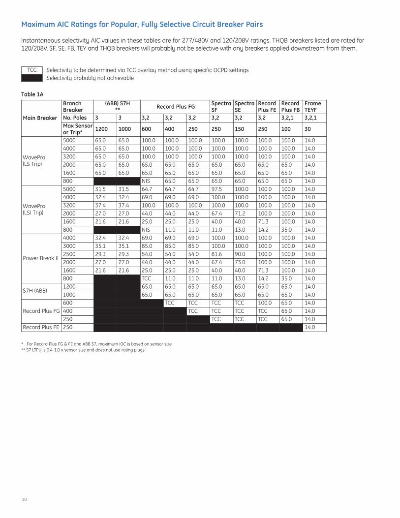
Maximum AIC Ratings for Popular, Fully Selective Circuit Breaker Pairs
Instantaneous selectivity AIC values in these tables are for 277/480V and 120/208V ratings. THQB breakers listed are rated for120/208V. SF, SE, FB, TEY and THQB breakers will probably not be selective with any breakers applied downstream from them.
Selectivity to be determined via TCC overlay method using specific OCPD settingsSelectivity probably not achievable
Table 1A
* For Record Plus FG & FE and ABB S7, maximum IOC is based on sensor size** S7 LTPU is 0.4-1.0 x sensor size and does not use rating plugs
Main Breaker
BranchBreaker
(ABB) S7H** Record Plus FG Spectra
SFSpectraSE
RecordPlus FE
RecordPlus FB
FrameTEYF
No. Poles 3 3 3,2 3,2 3,2 3,2 3,2 3,2 3,2,1 3,2,1Max Sensoror Trip* 1200 1000 600 400 250 250 150 250 100 30
WavePro (LS Trip)
5000 65.0 65.0 100.0 100.0 100.0 100.0 100.0 100.0 100.0 14.04000 65.0 65.0 100.0 100.0 100.0 100.0 100.0 100.0 100.0 14.03200 65.0 65.0 100.0 100.0 100.0 100.0 100.0 100.0 100.0 14.02000 65.0 65.0 65.0 65.0 65.0 65.0 65.0 65.0 65.0 14.01600 65.0 65.0 65.0 65.0 65.0 65.0 65.0 65.0 65.0 14.0800 NIS 65.0 65.0 65.0 65.0 65.0 65.0 14.0
WavePro (LSI Trip)
5000 31.5 31.5 64.7 64.7 64.7 97.5 100.0 100.0 100.0 14.04000 32.4 32.4 69.0 69.0 69.0 100.0 100.0 100.0 100.0 14.03200 37.4 37.4 100.0 100.0 100.0 100.0 100.0 100.0 100.0 14.02000 27.0 27.0 44.0 44.0 44.0 67.4 71.2 100.0 100.0 14.01600 21.6 21.6 25.0 25.0 25.0 40.0 40.0 71.3 100.0 14.0800 NIS 11.0 11.0 11.0 13.0 14.2 35.0 14.0
Power Break II
4000 32.4 32.4 69.0 69.0 69.0 100.0 100.0 100.0 100.0 14.03000 35.1 35.1 85.0 85.0 85.0 100.0 100.0 100.0 100.0 14.02500 29.3 29.3 54.0 54.0 54.0 81.6 90.0 100.0 100.0 14.02000 27.0 27.0 44.0 44.0 44.0 67.4 73.0 100.0 100.0 14.01600 21.6 21.6 25.0 25.0 25.0 40.0 40.0 71.3 100.0 14.0800 TCC 11.0 11.0 11.0 13.0 14.2 35.0 14.0
S7H (ABB)1200 65.0 65.0 65.0 65.0 65.0 65.0 65.0 14.01000 65.0 65.0 65.0 65.0 65.0 65.0 65.0 14.0
Record Plus FG600 TCC TCC TCC TCC 100.0 65.0 14.0400 TCC TCC TCC TCC 65.0 14.0250 TCC TCC TCC 65.0 14.0
Record Plus FE 250 14.0
TCC

11
Table 1B
Table 1C120/240V breaker ratingsFor 120/240V breaker pairs not listed below, use selective values from the 208 & 480V table above.
Main Breaker
BranchBreaker Record Plus FG Spectra
SFSpectraSE
RecordPlus FB
No. Poles 3,2 3,2 3,2 3,2 3,2 3,2,1Max Sensoror Trip 600 400 250 250 150 100
WavePro (LSI Trip)
5000 130 130 130 130 130 1004000 130 130 130 130 130 1003200 130 130 130 130 130 1002000 130 65 65 130 130 651600 130 65 65 130 130 65800 TCC 10 10 130 130 65
Power Break II
4000 100 100 100 100 100 1003000 100 100 100 100 100 1002500 92 92 92 100 100 1002000 75 75 75 85 85 851600 42 42 42 72 72 85800 TCC 10 10 14 17 32
Main Breaker
BranchBreaker Frame TEY Q-Line THQB
No. Poles 3,2 1 3,2 1 3,2 1 2 3, 2 3, 2, 1 3 1Max Sensoror Trip 100 100 60 60 30 30 125 100 60 30 30
WavePro (LS Trip)
5000 14.0 14.0 14.0 14.0 14.0 14.0 22.0 22.0 22.0 22.0 22.04000 14.0 14.0 14.0 14.0 14.0 14.0 22.0 22.0 22.0 22.0 22.03200 14.0 14.0 14.0 14.0 14.0 14.0 22.0 22.0 22.0 22.0 22.02000 14.0 14.0 14.0 14.0 14.0 14.0 22.0 22.0 22.0 22.0 22.01600 14.0 14.0 14.0 14.0 14.0 14.0 22.0 22.0 22.0 22.0 22.0800 14.0 14.0 14.0 14.0 14.0 14.0 22.0 22.0 22.0 22.0 22.0
WavePro (LSI Trip)
5000 14.0 14.0 14.0 14.0 14.0 14.0 22.0 22.0 22.0 22.0 22.04000 14.0 14.0 14.0 14.0 14.0 14.0 22.0 22.0 22.0 22.0 22.03200 14.0 14.0 14.0 14.0 14.0 14.0 22.0 22.0 22.0 22.0 22.02000 14.0 14.0 14.0 14.0 14.0 14.0 22.0 22.0 22.0 22.0 22.01600 14.0 14.0 14.0 14.0 14.0 14.0 22.0 22.0 22.0 22.0 22.0800 12.8 12.8 12.8 12.8 12.8 12.8 18.1 18.1 18.1 18.1 18.1
Power Break II
4000 14.0 14.0 14.0 14.0 14.0 14.0 22.0 22.0 22.0 22.0 22.03000 14.0 14.0 14.0 14.0 14.0 14.0 22.0 22.0 22.0 22.0 22.02500 14.0 14.0 14.0 14.0 14.0 14.0 22.0 22.0 22.0 22.0 22.02000 14.0 14.0 14.0 14.0 14.0 14.0 22.0 22.0 22.0 22.0 22.01600 14.0 14.0 14.0 14.0 14.0 14.0 22.0 22.0 22.0 22.0 22.0800 12.8 12.8 12.8 12.8 12.8 12.8 18.1 18.1 18.1 18.1 18.1
S7H (ABB)1200 14.0 14.0 14.0 14.0 14.0 14.0 22.0 22.0 22.0 22.0 22.01000 14.0 14.0 14.0 14.0 14.0 14.0 22.0 22.0 22.0 22.0 22.0
Record Plus FG600 6.0 6.0 10.0 10.0 14.0 14.0 22.0 22.0 22.0 22.0 22.0400 4.0 4.0 10.0 10.0 14.0 14.0 22.0 22.0 22.0 22.0 22.0250 2.5 2.5 2.5 2.5 14.0 14.0 2.5 2.5 10.0 22.0 22.0
Record Plus FE 250 TCC TCC TCC TCC 10.0 10.0 TCC TCC 4.0 6.0 14.0

12
Table 2GE Circuit Breaker / Equipment Combinations
Breakers
Equipment
EnclosureMounted
A-Series IIPanelboards A-Series II
PowerpanelSpectraPowerpanels
Switchboards Switchgear
AQ AE AD AV-1,2,5 AV-3 PB II AKD10 Entellisys AKD20
Main
WavePro without IOC 3 3 3 3
WavePro with IOC 3 3 3 3
EntelliGuard without IOC 3
EntelliGuard with IOC 3
EntelliGuard G without IOC 3
EntelliGuard G with IOC 3
Power Break II 3 3 3
ABB S7 3 3
Record Plus FG 8/08 3 3
Record Plus FE 2009 2009
Feeder
WavePro without IOC 3 3
WavePro with IOC 3 3
EntelliGuard without IOC 3
EntelliGuard with IOC 3
EntelliGuard G without IOC 3
EntelliGuard G with IOC 3
Power Break II 3 3 3
ABB S7 ABB 3
Record Plus FG 3 3
Record Plus FE 2009 8/08 3
Record Plus FB 3 3 3 8/08TEY / TEYF 3 3 3 3
THQ 3 3 3 3 3

13
Appendix
Selective Time–Current Curve TemplatesThe followed time-current curves were composed with the following objectives:
1. Achieve full selectivity (LT, ST and IOC) between each pair of circuit breakers applied2. Provide required NEC transformer protection3. Provide recommended ANSI through fault protection of transformers4. Provide the secondary power panel protection in accordance with its ampacity
(Note: To be “fully selective,” there must be no overlap of the long time and short time characteristics of an upstream anddownstream circuit breaker pair. If the IOC function of this pair of breakers overlap, then their instantaneous selectivity mustbe identified as selective in the manufacturer’s instantaneous overcurrent selectivity application literature.)
While it may be desirable to have the primary and secondary main circuit breakers selective with one another, it is not usualwhen applying MCCBs to protect transformers. In the 2008 NEC, a specific exception was added to exempt selectivityrequirements from the primary and secondary mains. The branch circuit breakers shown are the largest possible breakers andtrips that will be fully selective with both the upstream primary and secondary main transformer circuit breakers. If selectivitybetween the branch breakers and the upstream secondary main is not apparent because of IOC TCC overlap, the applicationis fully selective based on the tabular pairing cited in DET-537, GE Overcurrent Device Instantaneous Selectivity Tables.
One other item of note is that the maximum AIC values shown in DET-537 are symmetrical values. All analysis and testingdone to validate these numbers were done with the appropriate standard based X/R value and corresponding asymmetricaloffset. The equivalent symmetrical value was placed in the tables. It has long been standard practice to terminate the IOCfunction on a TCC at the maximum asymmetrical value of fault current, as IOC functions are often responsive to the peakvalue of current.
The partial system templates diagrammed on the following TCCs were laid out and modeled based on a maximum fault currentof 65 kA at 480V, with an X/R ratio of 4.9. Transformer impedances used are the minimum for which a full selectivity solutioncould be achieved. Also noted on the TCCs are the typical GE transformer impedances for aluminum wound, 150°C ratedtransformers. In every case, the impedance diagrammed is equal to or less than the typical GE value. To make the solutionas conservative as possible, no or negligible cable impedances were included in the short circuit calculations.
While Article 450 of the NEC requires that transformers be properly protected from overcurrent conditions, it allows severalalternative approaches to achieve protection. For 480V to 120/208V lighting transformers, 15 kVA and larger, the protectionrequirements are described in Table 450.3B of the NEC. The two options described are to use a circuit breaker as the primarymain rated at no more than 250% of the primary ampere rating and a secondary main circuit breaker rated at no more than125% of the secondary. (Note: See NEC Table 450.3 and associated notes for additional application allowances and restrictions.)It is also permissible to use only a primary main circuit breaker rated at no more than 125% of the primary ampacity.
In general, since the ANSI “through” fault protection criteria is a recommendation, it is desirable to have the ANSI protectioncharacteristic to the right of the primary and secondary circuit breaker TCCs. However, it is the standard practice that adequateprotection is still provided if most of the ANSI characteristic is to the right of the secondary main TCC.
In the TCCs that follow, A is always the transformer primary main and B is the secondary main circuit breaker.

14
15 kVA Transformer Template (with Record Plus Type FB Primary Main)
BUS-1
BUS-2
65 KAIC (SYM)
15 KVA
A
B
C*
480V
208V
3.5%
GE Record Plus MCCBFrame Type: FBNFrame Size: 100ATrip: 25A
GE TEY MCCBFrame Type: TEYFrame Size: 100ATrip: 50A
* GE Q-Line MCCBFrame Type: THQBFrame Size: 100ATrip: 20A
C
B
A
Notes:Where an overlap of the time-current curve, instantaneous overcurrent characteristicsseem to indicate non-selectivity, GE Overcurrent Instantaneous Selectivity Tables, DET-537,were used to validate selective operation.
Unless otherwise noted, overcurrent protective devices shown are for all available poleconfigurations.
GE typical transformer impedance: 150°C rise, aluminum winding, Z = 6.1%This Z% is equal to or greater than the minimum allowed on this coordination plot
* Base layer circuit breaker settings are “not to exceed” values

15
CURRENT IN AMPERES X 10 AT 208 VOLTS
CURRENT IN AMPERES X 10 AT 208 VOLTS
Time-current CurveFully Selective Solution for 15 kVA Transformer
The following parameters are the basis of the above selectivecoordination plot:Minimum allowable Z% = 3.5%65 kA (X/R=4.9) @ 480V; 1.2 kA @ 208V
.5
.5
.6
.6
.8
.8
1
1
2
2
3
3
4
4
5
5
6
6
7
7
8
8
9
9
10
10
2
2
3
3
4
4
5
5
6
6
7
7
8
8
9
9
100
100
2
2
3
3
4
4
5
5
6
6
7
7
8
8
9
9
1000
1000
2
2
3
3
4
4
5
5
6
6
7
7
8
8
9
9
10000
10000
.01 .01
.02 .02
.03 .03
.04 .04
.05 .05
.06 .06
.07 .07
.08 .08
.09 .09.1 .1
.2 .2
.3 .3
.4 .4
.5 .5
.6 .6
.7 .7
.8 .8
.9 .91 1
2 2
3 3
4 45 56 67 78 89 9
10 10
20 20
30 30
40 4050 5060 6070 7080 8090 90
100 100
200 200
300 300
400 400500 500600 600700 700800 800900 900
1000 1000TI
ME
INSE
CO
ND
S
TIM
EIN
SEC
ON
DS
AGE Record PlusFBNFrame = 100ATrip = 25A
B1217A
BGE E150TEYFrame = 100ATrip = 50A
C*GE Q LineTHQBFrame = 100ATrip = 20A
15 KVA3.5%
15 KVAINRUSH
15 KVAFLA
16
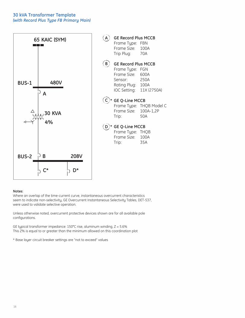
30 kVA Transformer Template (with Record Plus Type FB Primary Main)
C* D*
BUS-1
BUS-2
65 KAIC (SYM)
30 KVA
A
B
480V
208V
4%
GE Record Plus MCCBFrame Type: FBNFrame Size: 100ATrip Plug: 70A
GE Record Plus MCCBFrame Type: FGNFrame Size: 600ASensor: 250A Rating Plug: 100AIOC Setting: 11X (2750A)
* GE Q-Line MCCBFrame Type: THQB Model CFrame Size: 100A-1,2PTrip: 50A
* GE Q-Line MCCBFrame Type: THQBFrame Size: 100ATrip: 35A
D
C
B
A
Notes:Where an overlap of the time-current curve, instantaneous overcurrent characteristicsseem to indicate non-selectivity, GE Overcurrent Instantaneous Selectivity Tables, DET-537,were used to validate selective operation.
Unless otherwise noted, overcurrent protective devices shown are for all available poleconfigurations.
GE typical transformer impedance: 150°C rise, aluminum winding, Z = 5.6%This Z% is equal to or greater than the minimum allowed on this coordination plot
* Base layer circuit breaker settings are “not to exceed” values

17
CURRENT IN AMPERES X 10 AT 208 VOLTSTI
ME
INSE
CO
ND
S
TIM
EIN
SEC
ON
DS
CURRENT IN AMPERES X 10 AT 208 VOLTS
Time-current CurveFully Selective Solution for 30 kVA Transformer
The following parameters are the basis of the above selectivecoordination plot:Minimum allowable Z% = 4.0%65 kA (X/R=4.9) @ 480V; 2.1 kA @ 208V
.5
.5
.6
.6
.8
.8
1
1
2
2
3
3
4
4
5
5
6
6
7
7
8
8
9
9
10
10
2
2
3
3
4
4
5
5
6
6
7
7
8
8
9
9
100
100
2
2
3
3
4
4
5
5
6
6
7
7
8
8
9
9
1000
1000
2
2
3
3
4
4
5
5
6
6
7
7
8
8
9
9
10000
10000
.01 .01
.02 .02
.03 .03
.04 .04
.05 .05
.06 .06
.07 .07
.08 .08
.09 .09.1 .1
.2 .2
.3 .3
.4 .4
.5 .5
.6 .6
.7 .7
.8 .8
.9 .91 1
2 2
3 3
4 45 56 67 78 89 9
10 10
20 20
30 30
40 4050 5060 6070 7080 8090 90
100 100
200 200
300 300
400 400500 500600 600700 700800 800900 900
1000 1000
AGE Record PlusFBNFrame = 100ATrip = 70A
B2126A
BGE RecordPlusFGNFrame = 250ATrip = 100AInst = 11X (2750A)
C *GE Q LineTHQB Model C - 1,2PFrame = 100ATrip = 50A
D *GE Q LineTHQBFrame = 100ATrip = 35A
30 KVA4%
30 KVAINRUSH
30 KVAFLA
18
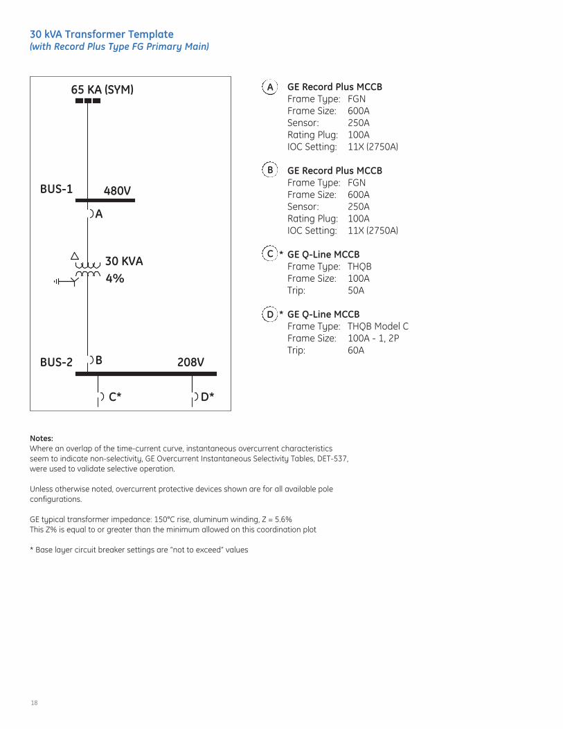
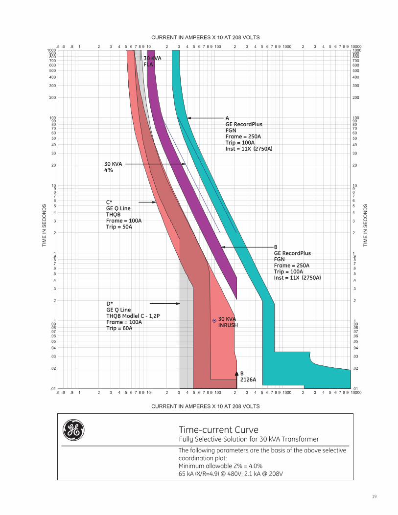
30 kVA Transformer Template (with Record Plus Type FG Primary Main)
BUS-1
BUS-2
65 KA (SYM)
30 KVA
A
B
C* D*
480V
208V
4%
GE Record Plus MCCBFrame Type: FGNFrame Size: 600ASensor: 250ARating Plug: 100AIOC Setting: 11X (2750A)
GE Record Plus MCCBFrame Type: FGNFrame Size: 600ASensor: 250A Rating Plug: 100AIOC Setting: 11X (2750A)
* GE Q-Line MCCBFrame Type: THQBFrame Size: 100ATrip: 50A
* GE Q-Line MCCBFrame Type: THQB Model CFrame Size: 100A - 1, 2PTrip: 60A
D
C
B
A
Notes:Where an overlap of the time-current curve, instantaneous overcurrent characteristicsseem to indicate non-selectivity, GE Overcurrent Instantaneous Selectivity Tables, DET-537,were used to validate selective operation.
Unless otherwise noted, overcurrent protective devices shown are for all available poleconfigurations.
GE typical transformer impedance: 150°C rise, aluminum winding, Z = 5.6%This Z% is equal to or greater than the minimum allowed on this coordination plot
* Base layer circuit breaker settings are “not to exceed” values
19
Time-current CurveFully Selective Solution for 30 kVA Transformer
The following parameters are the basis of the above selectivecoordination plot:Minimum allowable Z% = 4.0%65 kA (X/R=4.9) @ 480V; 2.1 kA @ 208V
CURRENT IN AMPERES X 10 AT 208 VOLTS
CURRENT IN AMPERES X 10 AT 208 VOLTS
TIM
EIN
SEC
ON
DS
TIM
EIN
SEC
ON
DS
.5
.5
.6
.6
.8
.8
1
1
2
2
3
3
4
4
5
5
6
6
7
7
8
8
9
9
10
10
2
2
3
3
4
4
5
5
6
6
7
7
8
8
9
9
100
100
2
2
3
3
4
4
5
5
6
6
7
7
8
8
9
9
1000
1000
2
2
3
3
4
4
5
5
6
6
7
7
8
8
9
9
10000
10000
.01 .01
.02 .02
.03 .03
.04 .04
.05 .05
.06 .06
.07 .07
.08 .08
.09 .09.1 .1
.2 .2
.3 .3
.4 .4
.5 .5
.6 .6
.7 .7
.8 .8
.9 .91 1
2 2
3 3
4 45 56 67 78 89 9
10 10
20 20
30 30
40 4050 5060 6070 7080 8090 90
100 100
200 200
300 300
400 400500 500600 600700 700800 800900 900
1000 1000
AGE RecordPlusFGNFrame = 250ATrip = 100AInst = 11X (2750A)
B2126A
BGE RecordPlusFGNFrame = 250ATrip = 100AInst = 11X (2750A)
C*GE Q LineTHQBFrame = 100ATrip = 50A
D*GE Q LineTHQB Modlel C - 1,2PFrame = 100ATrip = 60A
30 KVA4%
30 KVAINRUSH
30 KVAFLA

20
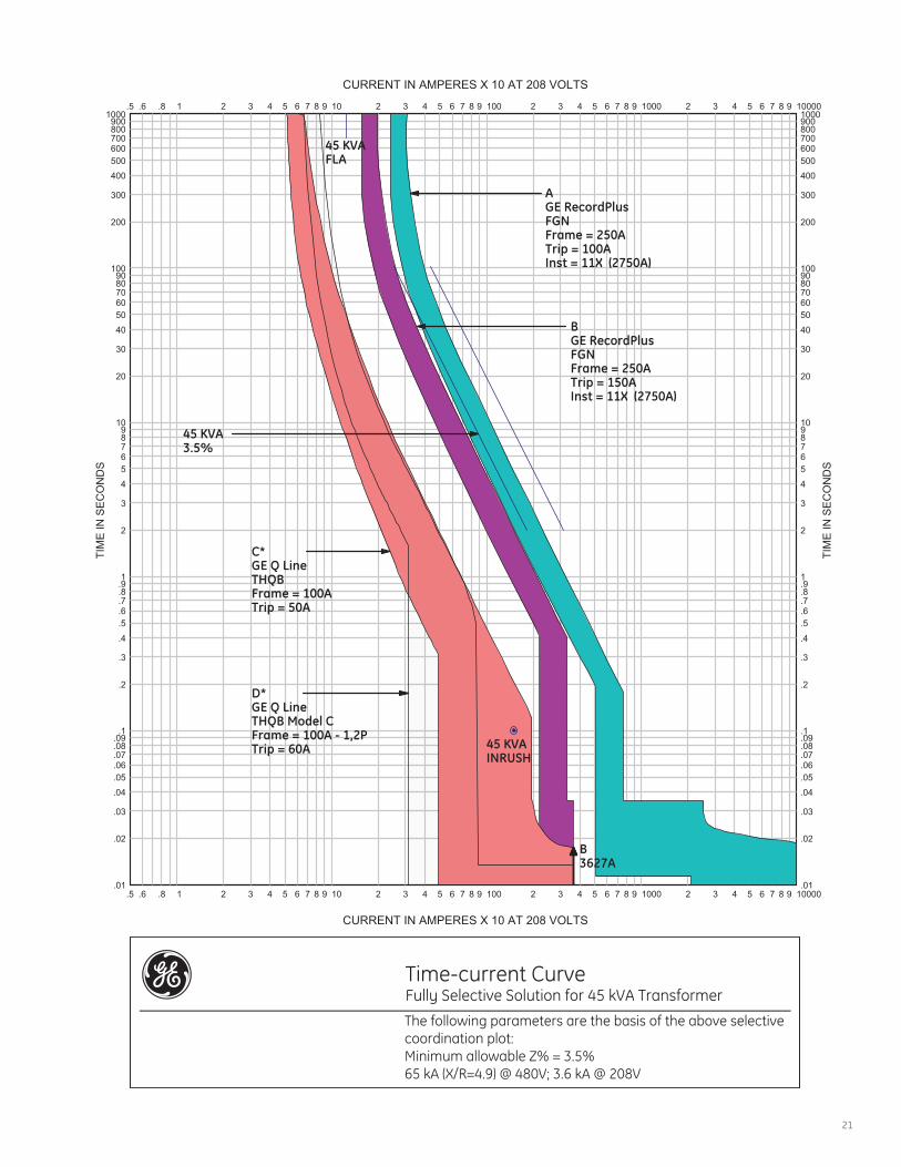
45 kVA Transformer Template (with Record Plus Type FG Primary Main)
BUS-1
BUS-2
65 KA (SYM)
45 KVA
A
B
C* D*
480V
208V
3.5%
GE Record Plus MCCBFrame Type: FGNFrame Size: 600ASensor: 250ATrip: 100AIOC Setting: 11X (2750A)
GE Record Plus MCCBFrame Type: FGNFrame Size: 600ASensor: 250A Trip: 150AIOC Setting: 11X (2750A)
* GE Q-Line MCCBFrame Type: THQBFrame Size: 100ATrip: 50A
* GE Q-Line MCCBFrame Type: THQB Model CFrame Size: 100A - 1, 2PTrip: 60A
D
C
B
A
Notes:Where an overlap of the time-current curve, instantaneous overcurrent characteristicsseem to indicate non-selectivity, GE Overcurrent Instantaneous Selectivity Tables, DET-537,were used to validate selective operation.
Unless otherwise noted, overcurrent protective devices shown are for all available poleconfigurations.
GE typical transformer impedance: 150°C rise, aluminum winding, Z = 5.4%This Z% is equal to or greater than the minimum allowed on this coordination plot
* Base layer circuit breaker settings are “not to exceed” values
21
Time-current CurveFully Selective Solution for 45 kVA Transformer
The following parameters are the basis of the above selectivecoordination plot:Minimum allowable Z% = 3.5%65 kA (X/R=4.9) @ 480V; 3.6 kA @ 208V
CURRENT IN AMPERES X 10 AT 208 VOLTS
CURRENT IN AMPERES X 10 AT 208 VOLTS
TIM
EIN
SEC
ON
DS
TIM
EIN
SEC
ON
DS
.5
.5
.6
.6
.8
.8
1
1
2
2
3
3
4
4
5
5
6
6
7
7
8
8
9
9
10
10
2
2
3
3
4
4
5
5
6
6
7
7
8
8
9
9
100
100
2
2
3
3
4
4
5
5
6
6
7
7
8
8
9
9
1000
1000
2
2
3
3
4
4
5
5
6
6
7
7
8
8
9
9
10000
10000
.01 .01
.02 .02
.03 .03
.04 .04
.05 .05
.06 .06
.07 .07
.08 .08
.09 .09.1 .1
.2 .2
.3 .3
.4 .4
.5 .5
.6 .6
.7 .7
.8 .8
.9 .91 1
2 2
3 3
4 45 56 67 78 89 9
10 10
20 20
30 30
40 4050 5060 6070 7080 8090 90
100 100
200 200
300 300
400 400500 500600 600700 700800 800900 900
1000 1000
AGE RecordPlusFGNFrame = 250ATrip = 100AInst = 11X (2750A)
B3627A
BGE RecordPlusFGNFrame = 250ATrip = 150AInst = 11X (2750A)
C*GE Q LineTHQBFrame = 100ATrip = 50A
D*GE Q LineTHQB Model CFrame = 100A - 1,2PTrip = 60A
45 KVA3.5%
45 KVAINRUSH
45 KVAFLA
22
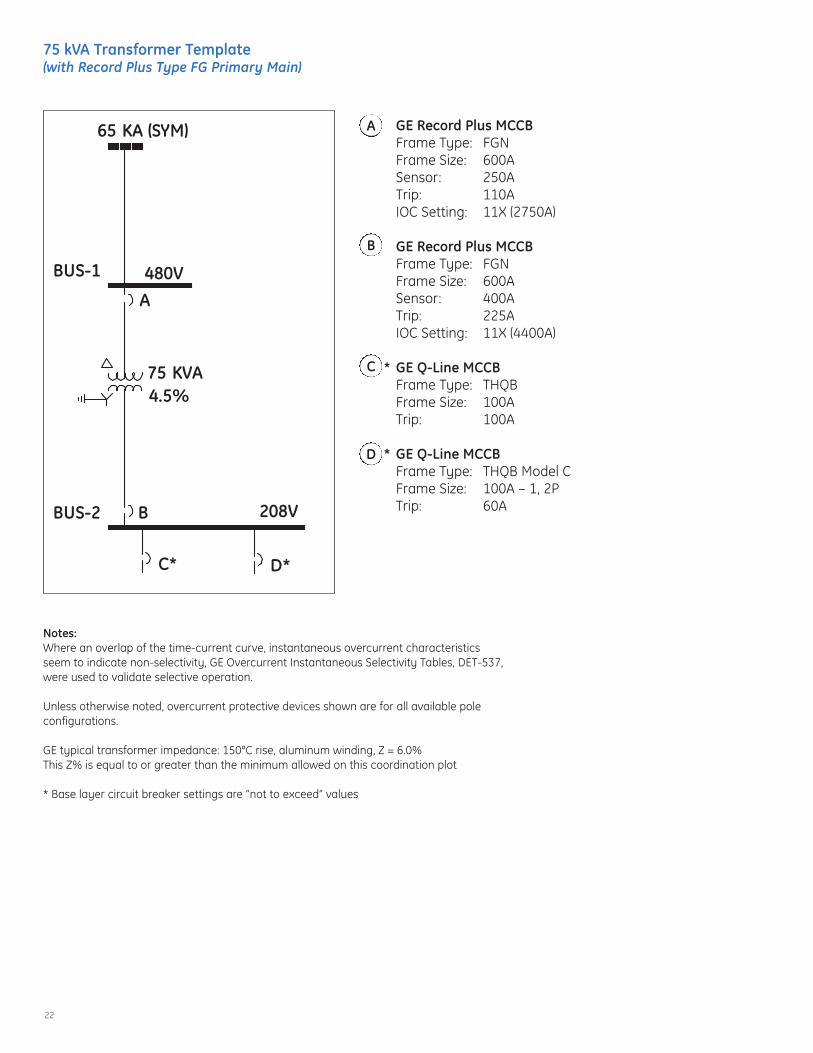
75 kVA Transformer Template (with Record Plus Type FG Primary Main)
BUS-1
BUS-2
65 KA (SYM)
75 KVA
A
B
C* D*
480V
208V
4.5%
GE Record Plus MCCBFrame Type: FGNFrame Size: 600ASensor: 250ATrip: 110AIOC Setting: 11X (2750A)
GE Record Plus MCCBFrame Type: FGNFrame Size: 600ASensor: 400A Trip: 225AIOC Setting: 11X (4400A)
* GE Q-Line MCCBFrame Type: THQBFrame Size: 100ATrip: 100A
* GE Q-Line MCCBFrame Type: THQB Model CFrame Size: 100A – 1, 2PTrip: 60A
D
C
B
A
Notes:Where an overlap of the time-current curve, instantaneous overcurrent characteristicsseem to indicate non-selectivity, GE Overcurrent Instantaneous Selectivity Tables, DET-537,were used to validate selective operation.
Unless otherwise noted, overcurrent protective devices shown are for all available poleconfigurations.
GE typical transformer impedance: 150°C rise, aluminum winding, Z = 6.0%This Z% is equal to or greater than the minimum allowed on this coordination plot
* Base layer circuit breaker settings are “not to exceed” values

23
Time-current CurveFully Selective Solution for 75 kVA Transformer
The following parameters are the basis of the above selectivecoordination plot:Minimum allowable Z% = 4.5%65 kA (X/R=4.9) @ 480V; 4.7 kA @ 208V
CURRENT IN AMPERES X 10 AT 208 VOLTS
CURRENT IN AMPERES X 10 AT 208 VOLTSTI
ME
INSE
CO
ND
S
TIM
EIN
SEC
ON
DS
.5
.5
.6
.6
.8
.8
1
1
2
2
3
3
4
4
5
5
6
6
7
7
8
8
9
9
10
10
2
2
3
3
4
4
5
5
6
6
7
7
8
8
9
9
100
100
2
2
3
3
4
4
5
5
6
6
7
7
8
8
9
9
1000
1000
2
2
3
3
4
4
5
5
6
6
7
7
8
8
9
9
10000
10000
.01 .01
.02 .02
.03 .03
.04 .04
.05 .05
.06 .06
.07 .07
.08 .08
.09 .09.1 .1
.2 .2
.3 .3
.4 .4
.5 .5
.6 .6
.7 .7
.8 .8
.9 .91 1
2 2
3 3
4 45 56 67 78 89 9
10 10
20 20
30 30
40 4050 5060 6070 7080 8090 90
100 100
200 200
300 300
400 400500 500600 600700 700800 800900 900
1000 1000
AGE RecordPlusFGNFrame = 250ATrip = 110AInst = 11X (2750A)
B4704A
BGE RecordPlusFGNFrame = 400ATrip = 225AInst = 11X (4400A)
C*GE Q LineTHQBFrame = 100ATrip = 100A
D*GE Q LineTHQB Model CFrame = 100A - 1,2PTrip = 60A
75 KVA4.5%
75 KVAINRUSH
75 KVAFLA
24
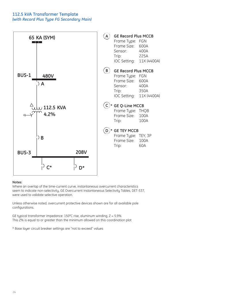
112.5 kVA Transformer Template (with Record Plus Type FG Secondary Main)
BUS-1
BUS-3
65 KA (SYM)
112.5 KVA
A
B
C* D*
480V
208V
4.2%
GE Record Plus MCCBFrame Type: FGNFrame Size: 600ASensor: 400ATrip: 225AIOC Setting: 11X (4400A)
GE Record Plus MCCBFrame Type: FGNFrame Size: 600ASensor: 400A Trip: 350AIOC Setting: 11X (4400A)
* GE Q-Line MCCBFrame Type: THQBFrame Size: 100ATrip: 100A
* GE TEY MCCBFrame Type: TEY, 3PFrame Size: 100ATrip: 60A
D
C
B
A
Notes:Where an overlap of the time-current curve, instantaneous overcurrent characteristicsseem to indicate non-selectivity, GE Overcurrent Instantaneous Selectivity Tables, DET-537,were used to validate selective operation.
Unless otherwise noted, overcurrent protective devices shown are for all available poleconfigurations.
GE typical transformer impedance: 150°C rise, aluminum winding, Z = 5.9%This Z% is equal to or greater than the minimum allowed on this coordination plot
* Base layer circuit breaker settings are “not to exceed” values

25
Time-current CurveFully Selective Solution for 112.5 kVA Transformer
The following parameters are the basis of the above selectivecoordination plot:Minimum allowable Z% = 4.2%65 kA (X/R=4.9) @ 480V; 7.5 kA @ 208V
CURRENT IN AMPERES X 10 AT 208 VOLTS
CURRENT IN AMPERES X 10 AT 208 VOLTS
TIM
EIN
SEC
ON
DS
TIM
EIN
SEC
ON
DS
.5
.5
.6
.6
.8
.8
1
1
2
2
3
3
4
4
5
5
6
6
7
7
8
8
9
9
10
10
2
2
3
3
4
4
5
5
6
6
7
7
8
8
9
9
100
100
2
2
3
3
4
4
5
5
6
6
7
7
8
8
9
9
1000
1000
2
2
3
3
4
4
5
5
6
6
7
7
8
8
9
9
10000
10000
.01 .01
.02 .02
.03 .03
.04 .04
.05 .05
.06 .06
.07 .07
.08 .08
.09 .09.1 .1
.2 .2
.3 .3
.4 .4
.5 .5
.6 .6
.7 .7
.8 .8
.9 .91 1
2 2
3 3
4 45 56 67 78 89 9
10 10
20 20
30 30
40 4050 5060 6070 7080 8090 90
100 100
200 200
300 300
400 400500 500600 600700 700800 800900 900
1000 1000
AGE RecordPlusFGNFrame = 400ATrip = 225AInst = 11X (4400A)
B7507A
BGE RecordPlusFGNFrame = 400ATrip = 350AInst = 11X (4400A)
C*GE Q LineTHQBFrame = 100ATrip = 100A
D*GE E150TEYFrame = 100ATrip = 60A
112.5 KVA4.2%
112.5 KVAINRUSH
112.5 KVAFLA

26
112.5 kVA Transformer Template (with ABB S7 Secondary Main)
BUS-1
BUS-2
BUS-3
65 KVA (SYM)
112.5 KVA
A
BC
D* E*
480V
208V
4.2%
GE Record Plus MCCBFrame Type: FGNFrame Size: 600ASensor: 400ATrip: 225AIOC Setting: 11X (4400A)
ABB S7 MCCBFrame Type: ISOMAXFrame Size: 1200ASensor: 1000A LT Trip: 0.4X (400A)LT Delay: AST Trip: 10X (10000A)ST Delay: DI2t: OutIOC Setting: 12X (12000A)
GE Record Plus MCCBFrame Type: FGNFrame Size: 600ASensor: 250ATrip: 225AIOC Setting: 11X (2750A)
* GE Q-Line MCCBFrame Type: THQBFrame Size: 100ATrip: 100A
* GE TEY MCCBFrame Type: TEYFrame Size: 100ATrip: 60A
E
D
C
B
A
Notes:Where an overlap of the time-current curve, instantaneous overcurrent characteristicsseem to indicate non-selectivity, GE Overcurrent Instantaneous Selectivity Tables, DET-537,were used to validate selective operation.
Unless otherwise noted, overcurrent protective devices shown are for all available poleconfigurations.
GE typical transformer impedance: 150°C rise, aluminum winding, Z = 5.9%This Z% is equal to or greater than the minimum allowed on this coordination plot
* Base layer circuit breaker settings are “not to exceed” values

27
Time-current CurveFully Selective Solution for 112.5 kVA Transformer
The following parameters are the basis of the above selectivecoordination plot:Minimum allowable Z% = 4.2%65 kA (X/R=4.9) @ 480V; 7.5 kA @ 208V
CURRENT IN AMPERES X 10 AT 208 VOLTS
CURRENT IN AMPERES X 10 AT 208 VOLTS
TIM
EIN
SEC
ON
DS
TIM
EIN
SEC
ON
DS
.5
.5
.6
.6
.8
.8
1
1
2
2
3
3
4
4
5
5
6
6
7
7
8
8
9
9
10
10
2
2
3
3
4
4
5
5
6
6
7
7
8
8
9
9
100
100
2
2
3
3
4
4
5
5
6
6
7
7
8
8
9
9
1000
1000
2
2
3
3
4
4
5
5
6
6
7
7
8
8
9
9
10000
10000
.01 .01
.02 .02
.03 .03
.04 .04
.05 .05
.06 .06
.07 .07
.08 .08
.09 .09.1 .1
.2 .2
.3 .3
.4 .4
.5 .5
.6 .6
.7 .7
.8 .8
.9 .91 1
2 2
3 3
4 45 56 67 78 89 9
10 10
20 20
30 30
40 4050 5060 6070 7080 8090 90
100 100
200 200
300 300
400 400500 500600 600700 700800 800900 900
1000 1000
C7507A
CGE RecordPlusFGNFrame = 250ATrip = 225AInst = 11X (2750A)
AGE RecordPlusFGNFrame = 400ATrip = 225AInst = 11X (4400A)
BABB PR212Sensor = S7 (1000ACT)Tap = 1000ACur Set = 0.4X (400A)LT Band = ASTPU = 10X (10000A)ST Delay = DSTPU I²t = OutInst = 12X (12000A)
D*GE Q LineTHQBFrame = 100ATrip = 100A
E*GE E150TEYFrame = 100ATrip = 60A
112.5 KVA4.2%
112.5 KVAINRUSH
112.5 KVAFLA

28
150 kVA Transformer Template (with Record Plus Type FG Primary Main)
BUS-1
BUS-3
65 KVA (SYM)
150 KVA
A
B
C* D*
480V
208V
4.4%
GE Record Plus MCCBFrame Type: FBNFrame Size: 600ASensor: 400ATrip: 250AIOC Setting: 11X (4400A)
GE Record Plus MCCBFrame Type: FGNFrame Size: 600ASensor: 600A Rating Plug: 450AIOC Setting: 11X (6600A)
* GE Q-Line MCCBFrame Type: THQFrame Size: 100ATrip: 100A
* GE Q-Line MCCBFrame Type: THQB Model CFrame Size: 100A – 1, 2PTrip: 60A
D
C
B
A
Notes:Where an overlap of the time-current curve, instantaneous overcurrent characteristicsseem to indicate non-selectivity, GE Overcurrent Instantaneous Selectivity Tables, DET-537,were used to validate selective operation.
Unless otherwise noted, overcurrent protective devices shown are for all available poleconfigurations.
GE typical transformer impedance: 150°C rise, aluminum winding, Z = 4.4%This Z% is equal to or greater than the minimum allowed on this coordination plot
* Base layer circuit breaker settings are “not to exceed” values

29
Time-current CurveFully Selective Solution for 150 kVA Transformer
The following parameters are the basis of the above selectivecoordination plot:Minimum allowable Z% = 4.4%65 kA (X/R=4.9) @ 480V; 9.8 kA @ 208V
CURRENT IN AMPERES X 10 AT 208 VOLTS
CURRENT IN AMPERES X 10 AT 208 VOLTS
TIM
EIN
SEC
ON
DS
TIM
EIN
SEC
ON
DS
.5
.5
.6
.6
.8
.8
1
1
2
2
3
3
4
4
5
5
6
6
7
7
8
8
9
9
10
10
2
2
3
3
4
4
5
5
6
6
7
7
8
8
9
9
100
100
2
2
3
3
4
4
5
5
6
6
7
7
8
8
9
9
1000
1000
2
2
3
3
4
4
5
5
6
6
7
7
8
8
9
9
10000
10000
.01 .01
.02 .02
.03 .03
.04 .04
.05 .05
.06 .06
.07 .07
.08 .08
.09 .09.1 .1
.2 .2
.3 .3
.4 .4
.5 .5
.6 .6
.7 .7
.8 .8
.9 .91 1
2 2
3 3
4 45 56 67 78 89 9
10 10
20 20
30 30
40 4050 5060 6070 7080 8090 90
100 100
200 200
300 300
400 400500 500600 600700 700800 800900 900
1000 1000
AGE RecordPlusFGNFrame = 400ATrip = 250AInst = 11X (4400A)
B9806A
BGE RecordPlusFGNFrame = 600ATrip = 450AInst = 11X (6600A)
C*GE Q LineTHQBFrame = 100ATrip = 100A
D*GE Q LineTHQB Model CFrame = 100A - 1,2PTrip = 60A
150 KVA4.4%
150 KVAINRUSH
150 KVAFLA

30
150 kVA Transformer Template (with ABB S7 Primary Main)
BUS-1
BUS-2
BUS-3
65 KA (SYM)
150 KVA
A
B
C*
D* E*
480V
208V
4.4%
ABB S7 MCCBFrame Type: ISOMAXFrame Size: 1200ASensor: 1000A LT Trip: 0.4X (400A)LT Delay: AST Trip: 8X (80000A)ST Delay: DI2t: OutIOC Setting: 12X (12000A)
ABB S7 MCCBFrame Type: ISOMAXFrame Size: 1200ASensor: 1200A LT Trip: 0.4X (480A)LT Delay: BST Trip: 8X (9600A)ST Delay: CI2t: OutIOC Setting: 12X (14400A)
GE Record Plus MCCBFrame Type: FGNFrame Size: 600ASensor: 400ATrip: 350AIOC Setting: 11X (4400A)
* GE Q-Line MCCBFrame Type: THQBFrame Size: 100ATrip: 100A
* GE TEY MCCBFrame Type: TEYFrame Size: 100ATrip: 60A
E
D
C
B
A
Notes:Where an overlap of the time-current curve, instantaneous overcurrent characteristicsseem to indicate non-selectivity, GE Overcurrent Instantaneous Selectivity Tables, DET-537,were used to validate selective operation.
Unless otherwise noted, overcurrent protective devices shown are for all available poleconfigurations.
GE typical transformer impedance: 150°C rise, aluminum winding, Z = 4.4%This Z% is equal to or greater than the minimum allowed on this coordination plot
* Base layer circuit breaker settings are “not to exceed” values

31
Time-current CurveFully Selective Solution for 150 kVA Transformer
The following parameters are the basis of the above selectivecoordination plot:Minimum allowable Z% = 4.4%65 kA (X/R=4.9) @ 480V; 9.8 kA @ 208V
CURRENT IN AMPERES X 100 AT 208 VOLTS
CURRENT IN AMPERES X 100 AT 208 VOLTS
TIM
EIN
SEC
ON
DS
TIM
EIN
SEC
ON
DS
.5
.5
.6
.6
.8
.8
1
1
2
2
3
3
4
4
5
5
6
6
7
7
8
8
9
9
10
10
2
2
3
3
4
4
5
5
6
6
7
7
8
8
9
9
100
100
2
2
3
3
4
4
5
5
6
6
7
7
8
8
9
9
1000
1000
2
2
3
3
4
4
5
5
6
6
7
7
8
8
9
9
10000
10000
.01 .01
.02 .02
.03 .03
.04 .04
.05 .05
.06 .06
.07 .07
.08 .08
.09 .09.1 .1
.2 .2
.3 .3
.4 .4
.5 .5
.6 .6
.7 .7
.8 .8
.9 .91 1
2 2
3 3
4 45 56 67 78 89 9
10 10
20 20
30 30
40 4050 5060 6070 7080 8090 90
100 100
200 200
300 300
400 400500 500600 600700 700800 800900 900
1000 1000
A82179A
AABB PR212Sensor = S7 (1000ACT)Tap = 1000ACur Set = 0.4X (400A)LT Band = ASTPU = 8X (8000A)ST Delay = DSTPU I²t = OutInst = 12X (12000A)
B9806A
BABB PR212Sensor = S7 (1200ACT)Tap = 1200ACur Set = 0.4X (480A)LT Band = BSTPU = 8X (9600A)ST Delay = CSTPU I²t = OutInst = 12X (14400A)
C*GE RecordPlusFGNFrame = 400ATrip = 350AInst = 11X (4400A)
D*GE Q LineTHQBFrame = 100ATrip = 100A
E*GE E150TEYFrame = 100ATrip = 60A
150 KVA4.4%
150 KVAINRUSH
150 KVAFLA

32
225 kVA Transformer Template (with ABB S7 Secondary Main)
BUS-1
BUS-2
BUS-3
65KA (SYM)
225 KVA4.1%
A
B
C
D*
1
480V
208V
GE Record Plus MCCBFrame Type: FGNFrame Size: 600ASensor: 600ARating Plug: 450AIOC Setting: 11X (6600A)
ABB ISOMAX MCCBFrame Type: S7Frame Size: 1200ASensor: 1000A LT Setting: 0.7X (700A)LT Delay: BST Setting: 10X (10000A)ST Delay: DI2t: OutIOC Setting: 12X (12000A)
1 GE Record Plus MCCBFrame Type: FGNFrame Size: 600ASensor: 600ARating Plug: 400AIOC Setting: 11X (6600A)
* GE Q-Line MCCBFrame Type: THQBFrame Size: 100ATrip: 100A
D
C
B
A
Notes:Where an overlap of the time-current curve, instantaneous overcurrent characteristicsseem to indicate non-selectivity, GE Overcurrent Instantaneous Selectivity Tables, DET-537,were used to validate selective operation.
Unless otherwise noted, overcurrent protective devices shown are for all available poleconfigurations.
GE typical transformer impedance: 150°C rise, aluminum winding, Z = 7.0%This Z% is equal to or greater than the minimum allowed on this coordination plot
* Base layer circuit breaker settings are “not to exceed” values1 FG400 and FG600 are selective with all THQB MCCBs. Certain THQBs not selective with
FG250 MCCBs.

33
Time-current CurveFully Selective Solution for 225 kVA Transformer
The following parameters are the basis of the above selectivecoordination plot:Minimum allowable Z% = 4.1%65 kA (X/R=4.9) @ 480V; 16.3 kA @ 208V
CURRENT IN AMPERES X 10 AT 208 VOLTS
CURRENT IN AMPERES X 10 AT 208 VOLTS
TIM
EIN
SEC
ON
DS
TIM
EIN
SEC
ON
DS
.5
.5
.6
.6
.8
.8
1
1
2
2
3
3
4
4
5
5
6
6
7
7
8
8
9
9
10
10
2
2
3
3
4
4
5
5
6
6
7
7
8
8
9
9
100
100
2
2
3
3
4
4
5
5
6
6
7
7
8
8
9
9
1000
1000
2
2
3
3
4
4
5
5
6
6
7
7
8
8
9
9
10000
10000
.01 .01
.02 .02
.03 .03
.04 .04
.05 .05
.06 .06
.07 .07
.08 .08
.09 .09.1 .1
.2 .2
.3 .3
.4 .4
.5 .5
.6 .6
.7 .7
.8 .8
.9 .91 1
2 2
3 3
4 45 56 67 78 89 9
10 10
20 20
30 30
40 4050 5060 6070 7080 8090 90
100 100
200 200
300 300
400 400500 500600 600700 700800 800900 900
1000 1000
CGE RecordPlusFGNFrame = 600ATrip = 400AInst = 11X (6600A)
AGE RecordPlusFGNFrame = 600ATrip = 450AInst = 11X (6600A)
B16319A
BABB PR212Sensor = S7 (1000ACT)Tap = 1000ACur Set = 0.7X (700A)LT Band = BSTPU = 10X (10000A)ST Delay = DSTPU I²t = OutInst = 12X (12000A)
D*GE Q LineTHHQBFrame = 100ATrip = 100A
225 KVA4.1%
225 KVAINRUSH
225 KVAFLA

34
300 kVA Transformer Template (with ABB S7 Secondary Main)
BUS-1
BUS-2
BUS-3
65KAIC (SYM)
300 KVA
A
B
C
D* E*
4.0%
1
, 2
480V
208V
Notes:Where an overlap of the time-current curve, instantaneous overcurrent characteristics seem to indicate non-selec-tivity, GE Overcurrent Instantaneous Selectivity Tables, DET-537, were used to validate selective operation.
Unless otherwise noted, overcurrent protective devices shown are for all available pole configurations.
GE typical transformer impedance: 150°C rise, aluminum winding, Z = 7.4%This Z% is equal to or greater than the minimum allowed on this coordination plot
* Base layer circuit breaker settings are “not to exceed” values1 FG400 and FG600 are selective with all THQB MCCBs. Certain THHQBs not selective with FG250 MCCBs.2 THHQB can only be used if AIC is less than 22 kA at the THHQB MCCB
ABB ISOMAX MCCBFrame Type: S7Frame Size: 1200ASensor: 1000A LT Setting: 0.5X (500A)LT Delay: BST Setting: 10X (10000A)ST Delay: DI2t: OutIOC Setting: 12X (12000A)
ABB ISOMAX MCCBFrame Type: S7Frame Size: 1200ASensor: 1000A LT Setting: 1.0X (1000A)LT Delay: AST Setting: 10X (1000A)ST Delay: DI2t: OutIOC Setting: 12X (12000A)
1 GE Record Plus MCCBFrame Type: FGNFrame Size: 600ASensor: 600A Rating Plug: 500AIOC Setting: 11X (6600A)
*2 GE Q-Line MCCBFrame Type: THHQBFrame Size: 100ATrip: 100A
* GE Record Plus MCCBFrame Type: FBNFrame Size: 100ATrip: 100A
E
D
C
B
A

35
Time-current CurveFully Selective Solution for 300 kVA Transformer
The following parameters are the basis of the above selectivecoordination plot:Minimum allowable Z% = 4.0%65 kA (X/R=4.9) @ 480V; 22.4 kA @ 208V
CURRENT IN AMPERES X 10 AT 208 VOLTS
CURRENT IN AMPERES X 10 AT 208 VOLTS
TIM
EIN
SEC
ON
DS
TIM
EIN
SEC
ON
DS
.5
.5
.6
.6
.8
.8
1
1
2
2
3
3
4
4
5
5
6
6
7
7
8
8
9
9
10
10
2
2
3
3
4
4
5
5
6
6
7
7
8
8
9
9
100
100
2
2
3
3
4
4
5
5
6
6
7
7
8
8
9
9
1000
1000
2
2
3
3
4
4
5
5
6
6
7
7
8
8
9
9
10000
10000
.01 .01
.02 .02
.03 .03
.04 .04
.05 .05
.06 .06
.07 .07
.08 .08
.09 .09.1 .1
.2 .2
.3 .3
.4 .4
.5 .5
.6 .6
.7 .7
.8 .8
.9 .91 1
2 2
3 3
4 45 56 67 78 89 9
10 10
20 20
30 30
40 4050 5060 6070 7080 8090 90
100 100
200 200
300 300
400 400500 500600 600700 700800 800900 900
1000 1000
C22434AAsymmetrical
CGE RecordPlusFGNFrame = 600ATrip = 500AInst = 11X (6600A)
AABB PR212Sensor = S7 (1000ACT)Tap = 1000ACur Set = 0.5X (500A)LT Band = BSTPU = 10X (10000A)ST Delay = DSTPU I²t = OutInst = 12 X (12000A)
BABB PR212Sensor = S7 (1000ACT)Tap = 1000ACur Set = 1X (1000A)LT Band = ASTPU = 10 X (10000A)ST Delay = DSTPU I²t = OutInst = 12X (12000A)
D*GE Q LineTHHQBFrame = 100ATrip = 100A
E*GE Record PlusFBNFrame = 100ATrip = 100A
300 KVA4%
300 KVAINRUSH
300 KVAFLA

36
Typical GE Dry Type Transformer Data
Table 3480V Delta to 208/120V Wye, TP-1 Transformers
kVA °C RiseAluminum Copper
Cat. No. %R %X %Z X/R Cat. No. %R %X %Z X/R
15150 9T83B3871 5.1 3.3 6.1 0.6 9T83C9871 4.3 2.2 4.8 0.5115 9T83B3871G15 5.1 3.3 6.1 0.6 9T83C9871G15 4.3 2.2 4.8 0.580 9T83B3871G80 5.1 3.3 6.1 0.6 9T83C9871G80 1.3 2.1 2.5 1.6
30150 9T83B3872 3.7 4.2 5.6 1.1 9T83C9872 2.8 4.3 5.1 1.8115 9T83B3872G15 3.7 4.2 5.6 1.1 9T83C9872G15 2.8 4.3 5.1 1.880 9T83B3872G80 2.1 2.7 3.4 1.3 9T83C9872G80 1.9 2.3 3 1.2
45150 9T83B3873 3.5 4.1 5.4 1.2 9T83C9873 3 3.5 4.6 1.2115 9T83B3873G15 3.5 4.1 5.4 1.2 9T83C9873G15 3 3.5 4.6 1.280 9T83B3873G80 1.3 3.1 3.4 2.4 9T83C9873G80 1 2.5 2.7 2.5
75150 9T83B3874 3.9 4.5 6.0 1.2 9T83C9874 3.4 4 5.2 1.2115 9T83B3874G15 2.8 4.7 5.5 1.7 9T83C9874G15 2.7 3.5 4.4 1.380 9T83B3874G80 1.1 3.5 3.7 3.2 9T83C9874G80 1 2.6 2.8 2.6
112.5150 9T83B3875 3.1 5.0 5.9 1.6 9T83C9875 2.7 3.8 4.6 1.4115 9T83B3875G15 2.3 4.1 4.7 1.0 9T83C9875G15 2.5 4.8 5.4 1.980 9T40G0005G81 1.8 2.2 2.8 1.2 9T45G0005G81 1.5 1.9 2.4 1.3
150150 9T40G0006 2.4 3.7 4.4 1.5 9T45G0006 2 3.1 3.7 1.6115 9T40G0006G51 2.4 3.7 4.4 1.5 9T45G0006G51 2 3.1 3.7 1.680 9T40G0006G81 2.4 3.7 4.4 1.5 9T45G0006G81 2 3.1 3.7 1.6
225150 9T40G0007 4.3 5.6 7.0 1.3 9T45G0007 3.7 4.6 5.9 1.2115 9T40G0007G51 2.4 5.0 5.5 1.9 9T45G0007G51 2 3.8 4.3 1.980 9T40G0007G81 2.6 4.9 5.6 1.9 9T45G0007G81 2 3.8 4.3 1.9
300150 9T40G0008 4.0 6.2 7.4 1.6 9T45G0008 3.3 4.6 5.7 1.4115 9T40G0008G51 1.8 5.2 5.5 2.9 9T45G0008G51 1.6 3.2 3.5 2.0
37
Glossary
AbbreviationsAHJ Authority having jurisdictionAIC Amperes interrupting currentATS Automatic transfer switch FTL Feed through lugsICCB Insulated case circuit breaker (UL Standard 489 rated)IOC Instantaneous overcurrent kA Kilo-amperesLVPCB Low Voltage Power Circuit Breaker (ANSI Standard C37. rated)MCCB Molded Case Circuit Breaker (UL Standard 489 rated)MCS Molded Case SwitchNEC National Electric CodeOCPD Overcurrent Protective DeviceV Voltsxfmr Transformer
Terms As Used in This Publication0.1 second selectivityTwo adjacent OCPDs are selective with one another over the full range of AIC, but only down to 0.1 seconds on the TCC.This suggests that their long time and short time characteristics are selective with one another, but that their instantaneouscharacteristics (that portion of the TCC below 0.1 seconds) may not be selective
CodeNational Electrical Code
Downstream / UpstreamA circuit breaker’s or OCPDs location relative to the power source. For example, a main circuit breaker in a panel is closer tothe power source than a (smaller sized) branch breaker in the same panel is upstream of the branch breaker.Correspondingly, the branch breaker is downstream of the main breaker in this example.
Full SelectivityIn the context of NEC Articles 700, 701 and 708, this means two adjacent OCPDs are selective with one another over the fullrange of available fault current magnitudes and for all types of fault current.
LayerOn a one-line diagram, circuit breaker or OCPD layers are counted from a load back to a power source. Each circuit breakerplaced above another on the circuit back to the source is another layer.

imagination at work
GE41 Woodford Avenue, Plainville, CT 06062www.geelectrical.com
© 2008 General Electric Company
DET-654 (10/08)