designing with gabions - cms.esi.info · what are gabions? the term gabion refers to a modular...
TRANSCRIPT

Volume 1
A Reference Guide for the Designing of Mass Gravity Gabion
Walls
Designing with Gabions
Registered Office: Unit 5, The Cobden Centre, Folly Brook Road, Emerald Park, Emersons Green, Bristol BS16 7FQEnviromesh is a trading name of Cerana Limited. Registered in England No. 5065615
Contents
CONDITIONS & LIMITATIONS PAGE 1
INTRODUCTION PAGE 2
WHAT ARE GABIONS? PAGE 3
WELDED MESH GABIONS PAGE 4
WOVEN MESH GABIONS PAGE 5
GABION FILLING MATERIALS PAGE 6
SOIL CHARACTERISTICS PAGE 7 - 8
DESIGN METHODS PAGE 9
DESIGN ANALYSIS PAGE 10
ACTIVE THRUST CALCULATIONS PAGES 11 - 12
GABION COMPUTATIONS PAGES 13 - 17- stability calculations - design criteria and gabion densities- complex crest profiles
DESIGN EXAMPLE PAGES 18 - 20
CAD DESIGN EXAMPLE PAGES 21 - 24
TYPICAL GABION SECTIONS PAGES 25 - 35- gabion 27 system- gabion 39 system
SYSTEM COMPARISON PAGE 36 - Gabion 27 V Gabion 39
SPECIFICATIONS PAGES 37 - 44
- gabion 27 system- welded mesh gabion 39 system - 3mm - welded mesh gabion 39 system - 4mm- welded mesh gabion 39 system - 3/4mm - welded mesh gabion 39 system - 5mm- woven mesh zinc coated gabions- woven mesh zinc/PVC coated gabions
TIPS ON GABION WALL DESIGN PAGE 45
Conditions & Limitations
The copyright, design right or other intellectual property in this guide and the products set out herein shall as between Cerana Limited, trading under the Trade Mark of Enviromesh and any customer or potential customer of Enviromesh be the property of Enviromesh.
This publication is intended as a general overview of the subjects dealt with and is not intended and should not be used as a substitute for taking detailed and specific advice in any specific situation. The recommendation and advice given in this booklet is given withoutliability on the part of Enviromesh or its employees and should not be relied upon for any particular action or inaction.
Enviromesh shall not be liable to compensate any other party for any loss, including any consequential loss, arising out of any inaccuracies in or omissions from this guide.
It is the responsibility of all parties to satisfy themselves that the designs, calculations and specifications set out in proposals submitted by Enviromesh are correct and no responsibility is accepted by Enviromesh for the accuracy of the designs and specificationsincluded in such proposals.
EnviromeshGarner Street Business ParkEtruria Stoke-on-TrentStaffordshireST4 7BH
Tel: 0044 (0) 845 136 0101Fax: 0044 (0) 845 136 0202Email: [email protected]: www.enviromeshgabions.com
1
Introduction
Gabions have long become an established method of construction for retaining structures worldwide, providing economical and environmentally acceptable solutions.
These structures are generally designed as mass gravity walls with either stepped or flush faces depending upon the requirements of the engineer.
This design guide has been prepared to assist competent structural / civil engineers and architects in the best practice of designing gabion walls.
Alternatively, Enviromesh can provide a free desk top design feasibility service using dedicated in house software.
This technical service is to support our clients with a design facility aimed at providing the most economical system to meet the clients needs.
For advice or assistance with the design of a gabion wall, please call Enviromesh direct, on any of the contact details given at the end of this guide.
2
What are Gabions?
The term gabion refers to a modular containment system that enables rock, stone or other inert materials to be used as a construction material.
The modules or cages as they are known, are formed of wire mesh fabric panels, jointed to form square, rectangular or trapezoidal shaped units. These units are part pre-assembled in the factory to form a flat pack system.
These flat pack units are then supplied to the customer and formed into the final shaped module on site with the necessary lacing wire, helicals and / or rings as required. Each module has to be connected to adjacent modules to form a monolithic structure.
The types of mesh used, must be of a non ravelling type such as welded wire mesh or hexagonal woven wire mesh and provided with corrosion protection to suit the required exposure conditions.
The gabions are normally machined filled in layers with the contractor picking the stone over by hand to reduce excessive voids. The exposed faces are also systematically hand packed to provide an appearance of a dry stone wall.
Although some structures are only machine filled, this procedure is not normally recom-mended.
For gabion structures to perform correctly the quality of installation is of paramountimportant.
3
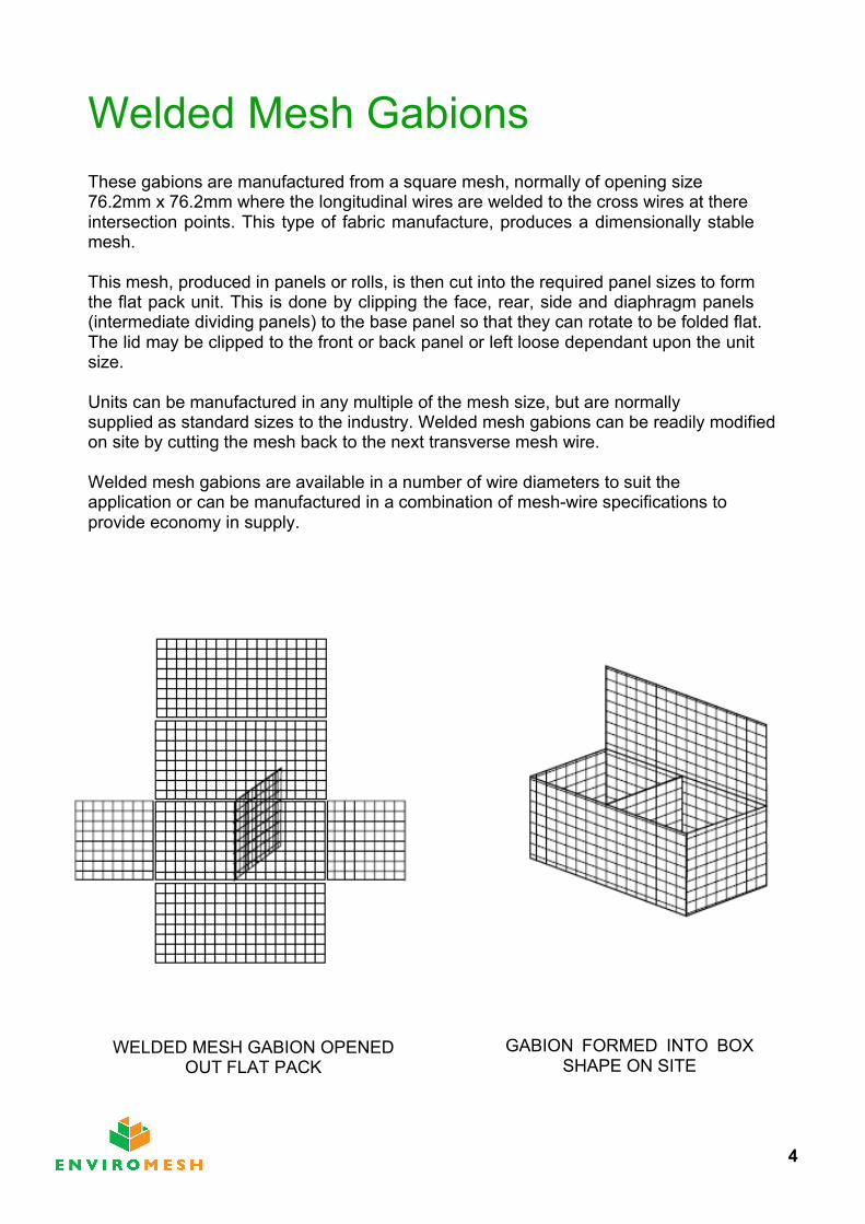
Welded Mesh GabionsThese gabions are manufactured from a square mesh, normally of opening size 76.2mm x 76.2mm where the longitudinal wires are welded to the cross wires at there intersection points. This type of fabric manufacture, produces a dimensionally stable mesh.
This mesh, produced in panels or rolls, is then cut into the required panel sizes to form the flat pack unit. This is done by clipping the face, rear, side and diaphragm panels (intermediate dividing panels) to the base panel so that they can rotate to be folded flat. The lid may be clipped to the front or back panel or left loose dependant upon the unit size.
Units can be manufactured in any multiple of the mesh size, but are normally supplied as standard sizes to the industry. Welded mesh gabions can be readily modified on site by cutting the mesh back to the next transverse mesh wire.
Welded mesh gabions are available in a number of wire diameters to suit the application or can be manufactured in a combination of mesh-wire specifications to provide economy in supply.
The resultant gabions flexibility is dependant upon the choice of wire diameter.
WELDED MESH GABION OPENED OUT FLAT PACK
GABION FORMED INTO BOX SHAPE ON SITE
4

Woven Mesh GabionsThese gabions are manufactured from a mesh that has a hexagonal opening which is formed by twisting pairs of wire together with one and a half turns (sometimes referred to as triple or double twist).
This type of mesh production is continuous. To form panels, the mesh is guillotined across the weave and the cut ends of the wire are wrapped around a heavier wire to form a selvedge end.
The unit is factory fabricated from one main panel which forms the front, base, rear and lid of the unit with additional panels connected to the base section of the main panel to form the diaphragm and end panels. Dependant upon the manufacturer, the mesh orientation is normally either with the weave horizontal or vertical on the face panel and the connection of the ends and diaphragm to the base is via a spiral wire or pairs of twist-ed wires, twisted together around the base mesh.
This type of mesh is a flexible mesh as it can articulate about the twists. It is normally manufactured from a 2.7mm wire diameter. The coatings are either galvanised only, gal-vanised and PVC coated or galvanised and HDPE coated. The dimension between the twists is a nominal 80mm.
HEXAGONAL MESH GABION OPENED OUT FLAT PACK
GABION FORMED INTO BOX SHAPE ON SITE
5
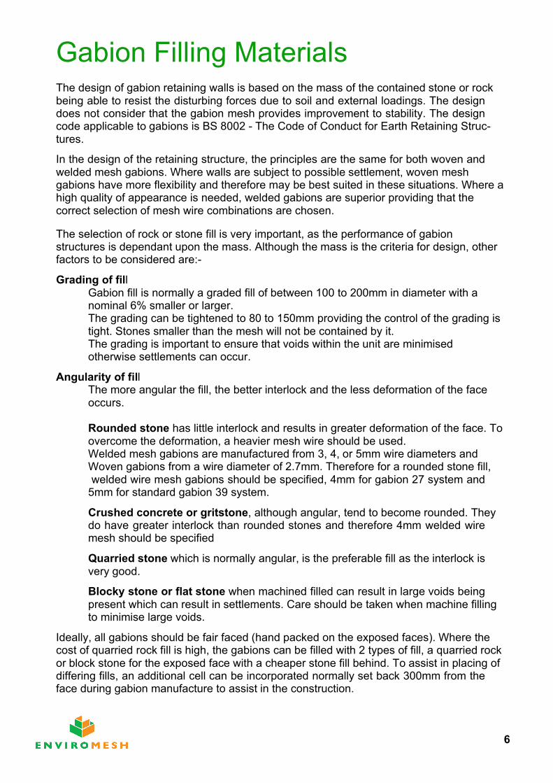
Gabion Filling MaterialsThe design of gabion retaining walls is based on the mass of the contained stone or rock being able to resist the disturbing forces due to soil and external loadings. The design does not consider that the gabion mesh provides improvement to stability. The design code applicable to gabions is BS 8002 - The Code of Conduct for Earth Retaining Struc-tures.
In the design of the retaining structure, the principles are the same for both woven and welded mesh gabions. Where walls are subject to possible settlement, woven mesh gabions have more flexibility and therefore may be best suited in these situations. Where a high quality of appearance is needed, welded gabions are superior providing that thecorrect selection of mesh wire combinations are chosen.
The selection of rock or stone fill is very important, as the performance of gabion structures is dependant upon the mass. Although the mass is the criteria for design, other factors to be considered are:-
Grading of fillGabion fill is normally a graded fill of between 100 to 200mm in diameter with anominal 6% smaller or larger.The grading can be tightened to 80 to 150mm providing the control of the grading is tight. Stones smaller than the mesh will not be contained by it.The grading is important to ensure that voids within the unit are minimised otherwise settlements can occur.
Angularity of fillThe more angular the fill, the better interlock and the less deformation of the face occurs.
Rounded stone has little interlock and results in greater deformation of the face. To overcome the deformation, a heavier mesh wire should be used. Welded mesh gabions are manufactured from 3, 4, or 5mm wire diameters andWoven gabions from a wire diameter of 2.7mm. Therefore for a rounded stone fill, welded wire mesh gabions should be specified, 4mm for gabion 27 system and
5mm for standard gabion 39 system.
Crushed concrete or gritstone, although angular, tend to become rounded. They do have greater interlock than rounded stones and therefore 4mm welded wiremesh should be specified
Quarried stone which is normally angular, is the preferable fill as the interlock is very good.
Blocky stone or flat stone when machined filled can result in large voids being present which can result in settlements. Care should be taken when machine filling to minimise large voids.
Ideally, all gabions should be fair faced (hand packed on the exposed faces). Where the cost of quarried rock fill is high, the gabions can be filled with 2 types of fill, a quarried rock or block stone for the exposed face with a cheaper stone fill behind. To assist in placing of differing fills, an additional cell can be incorporated normally set back 300mm from the face during gabion manufacture to assist in the construction.
6
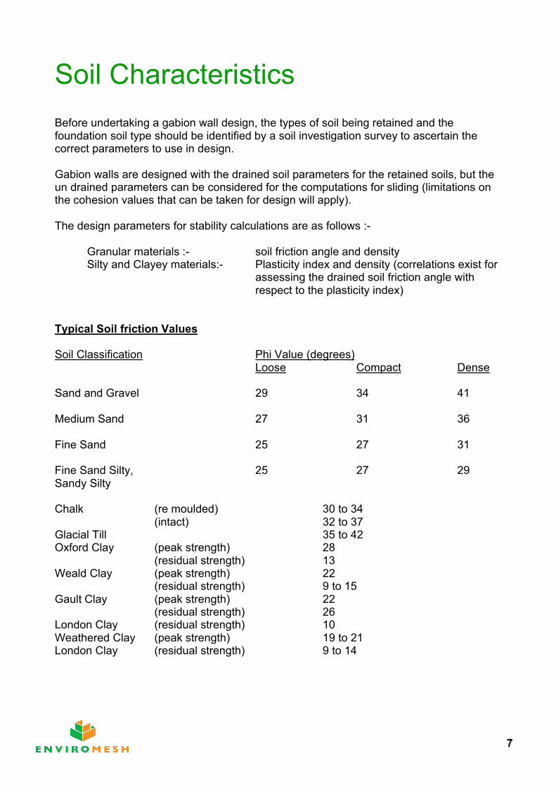
Soil CharacteristicsBefore undertaking a gabion wall design, the types of soil being retained and the foundation soil type should be identified by a soil investigation survey to ascertain the correct parameters to use in design.
Gabion walls are designed with the drained soil parameters for the retained soils, but the un drained parameters can be considered for the computations for sliding (limitations on the cohesion values that can be taken for design will apply).
The design parameters for stability calculations are as follows :-
Granular materials :- soil friction angle and densitySilty and Clayey materials:- Plasticity index and density (correlations exist for
assessing the drained soil friction angle withrespect to the plasticity index)
Typical Soil friction Values
Soil Classification Phi Value (degrees)Loose Compact Dense
Sand and Gravel 29 34 41
Medium Sand 27 31 36
Fine Sand 25 27 31
Fine Sand Silty, 25 27 29Sandy Silty
Chalk (re moulded) 30 to 34(intact) 32 to 37
Glacial Till 35 to 42Oxford Clay (peak strength) 28
(residual strength) 13Weald Clay (peak strength) 22
(residual strength) 9 to 15Gault Clay (peak strength) 22
(residual strength) 26London Clay (residual strength) 10Weathered Clay (peak strength) 19 to 21 London Clay (residual strength) 9 to 14
7
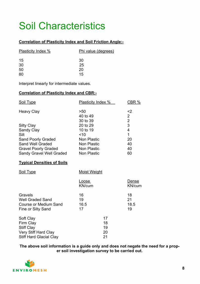
Soil CharacteristicsCorrelation of Plasticity Index and Soil Friction Angle:-
Plasticity Index % Phi value (degrees)
15 3030 2550 2080 15
Interpret linearly for intermediate values.
Correlation of Plasticity Index and CBR:-
Soil Type Plasticity Index % CBR %
Heavy Clay >50 <2 40 to 49 2 30 to 39 2
Silty Clay 20 to 29 3 Sandy Clay 10 to 19 4Silt <10 1Sand Poorly Graded Non Plastic 20Sand Well Graded Non Plastic 40Gravel Poorly Graded Non Plastic 40Sandy Gravel Well Graded Non Plastic 60
Typical Densities of Soils
Soil Type Moist Weight
Loose DenseKN/cum KN/cum
Gravels 16 18Well Graded Sand 19 21 Course or Medium Sand 16.5 18.5 Fine or Silty Sand 17 19
Soft Clay 17Firm Clay 18Stiff Clay 19Very Stiff Hard Clay 20Stiff Hard Glacial Clay 21
The above soil information is a guide only and does not negate the need for a prop-er soil investigation survey to be carried out.
8
Design Methods
Design methods of analysis for determining the stability of gabion walls are based on The Code of Practice BS 8002 which superseded CP2. The two methods considered are:-
- Serviceability Limit State Design - Ultimate Limit State Design
In the original code of practice, CP2, the analysis was based on Ultimate Limit State, where the structure had to meet certain factors of safety on sliding (1.5) and overturning (2.0). The soil forces being determined on the peak soil conditions.
BS 8002 recommends the Serviceability Limit State design where the factors of safety achieved must be greater than unity. The soil forces being determined on factored soil parameters.
At present, most design is still carried out on the Ultimate Limit State, but generally a Serviceability Limit State Design would give a similar section.
Gabion walls form typically a trapezoidal format, formed of a number of courses with the width of each course reducing as the wall height increases. The walls may be flush faced or stepped as required by design or visual requirements, and are normally inclined at 6 degrees to the vertical in the case of standard gabion 39 system and up to 10 degrees for the gabion 27 system.
To establish the initial cross section for evaluation, the base width considered is 0.7 x the wall height for standard gabion 39 system inclined at 6 degrees to the vertical and 0.55 x the height for gabion 27 system at an inclination of 10 degrees. The wall height for evalua-tion should allow for a minimum toe in of 0.3 to 0.5m dependant on soil type.
Based on a 3.0m high wall, the base widths would be:-
Standard Gabions 0.7 x 3.0 = 2.1m (nearest standard unit width is 2m)Gabion 27 System 0.55 x 3.0 = 1.65m (nearest standard unit width is 1.7m, a
design example is evaluated later)
The make up for the walls will then be:-Course Standard Gabion 39 System Gabion 27 System
(width x height) (width x height)
4 1.7 x 1.03 2.0 x 1.0 1.4 x 0.72 1.5 x 1.0 1.0 x 0.71 1.0 x 1.0 0.7 x 0.7Total Volume 4.5 cum 3.87cum
Note:- Gabon 27 system at an inclination of 10 degrees from the vertical normally provides a more economical section.
9
Design AnalysisOnce the initial section has been determined, stability checks can be carried out.
The provision for any superimposed surcharge loadings to the retained soil both in the construction stage and the permanent condition must be accounted for. Normally, a typical construction loading is taken as 10kN/sqm for retained soils with nominalinclinations. If unusual construction plant is to be used in the vicinity of the wall, then the superimposed loading should be increased accordingly.Where the retaining wall height is large or is built within a slope or in clayey material, it may be necessary to carry out an overall slope stability check in case a circular failure plane exists which passes beneath the structure in the soil strata.
Two methods of computing the soil forces on the retaining wall can be used,:-
Coulomb’s Analysis:-This is a mathematical analysis based on considering a coefficient of active thrust for the soil. The method considers the soil parameters and the friction developed at the back of the wall. The analysis is limited to retained soil profiles which have a single grade, but more complex slopes can be considered by rationalising the complex surface to a single grade and applying a continuous surcharge to approximate the profile. It can only consider a continuous single surcharge, but methods are available to deal with line or point load-ings on the retained soil.
Wedge Analysis:-This is a graphical solution that considers the forces acting on the soil wedge behind the wall to maintain it in equilibrium. The method considers various failure planes. For each plane, a force vector diagram is plotted and the maximum thrust can be determined from the locus of the active thrust vector on the diagram. This method is the preferred method of analysis as it can accommodate variations in the profile of the retained ground along with multiple surcharge loading conditions. However the analysis can be lengthy as it has to be carried out at each course and therefore is best managed by computer programs.
The software used by ENVIROMESH, computates using Wedge Analysis.
The following design method is based on Coulomb’s Analysis. Being mathematical it isrelatively easy to carry out design.
Data required for design
Geometry :- Slope wall height h mSlope angle of the retained soil degrees
Soil parameters Soil friction angle degreesDensity kN/cum
Loadings Surcharge po kN/sqmAllowable bearing pressure
10
Active Thrust CalculationsFrom the code of practice for gabions, the wall friction is taken as equal to where no geo-textile separator is required behind the wall and 0.9 x where a geotextile is required.
For the base frictional value, the code of practice suggests a value of 0.66 x however based on experience and historical test trials, the value can be taken as the same as the frictional value of the founding soil.
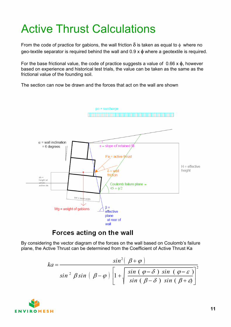
The section can now be drawn and the forces that act on the wall are shown
By considering the vector diagram of the forces on the wall based on Coulomb’s failure plane, the Active Thrust can be determined from the Coefficient of Active Thrust Ka
11
2
2
2
)()()()(1
nisnisnisnisnisnis
nisak
Active Thrust CalculationsActive thrust due to soil and surcharges are as follows:-
Pa soil = 0.5 x ka
Pa surcharge = po x ka
where Pa soil = active thrust due to soilPa surcharge = active thrust due to imposed loadingsH = effective wall heightpo = surcharge loading above the wall
Total Active thrust Pa
Pa=Pasoil + Pasurcharge
The active thrust due to the soil acts at 1/3rd the effective height of the wall and for the surcharge it acts at � the wall height. The resultant point of application of total active thrust above the toe of the wall can be calculated from :-
dh soil = H/3 [ (H + 3hs) / (H+ 2hs)]
dh = dh soil - bw x sin
where bw = base width of gabion structure hs = the equivalent height of soil equal to the
surcharge loading = po / s
Resolve the active thrust Pa into its horizontal and vertical components. Ph and Pvrespectively
Ph = Pa x cos ( 90 -
Pv = Pa x sin ( 90 -
des of soil if no geo-textile is required
x des of soil if geo-textile is present
12
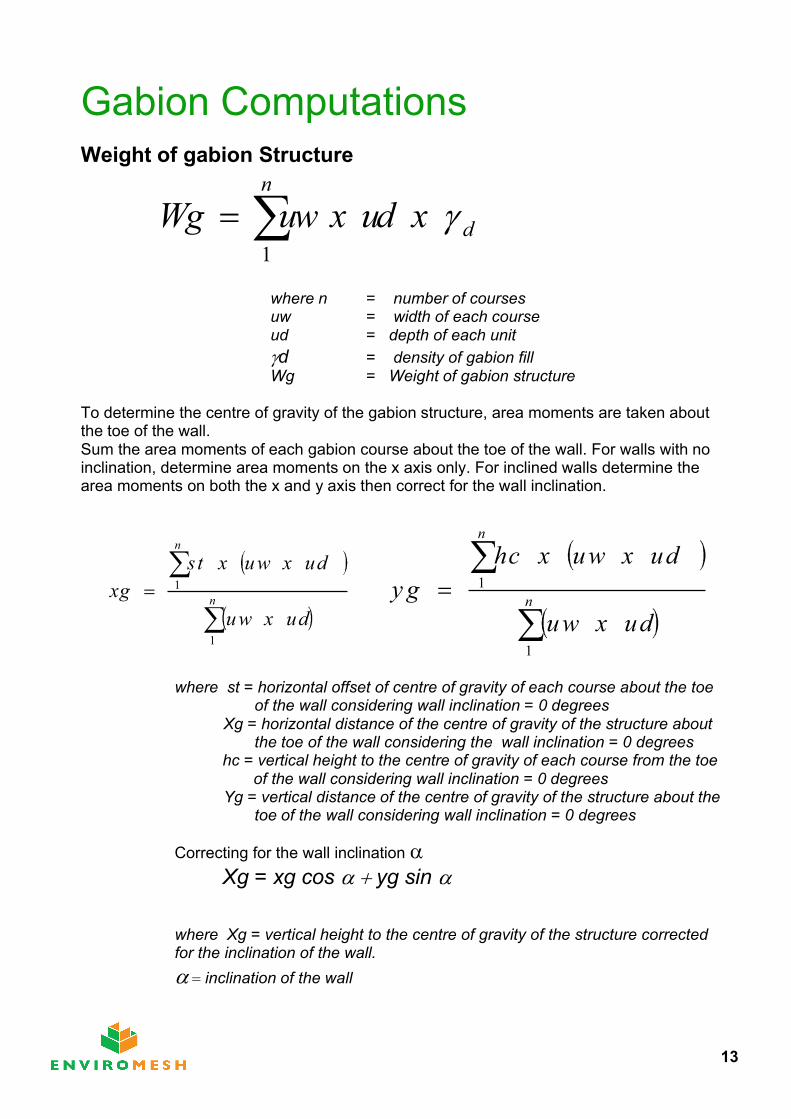
Gabion ComputationsWeight of gabion Structure
where n = number of coursesuw = width of each courseud = depth of each unitd = density of gabion fill
Wg = Weight of gabion structure To determine the centre of gravity of the gabion structure, area moments are taken about the toe of the wall. Sum the area moments of each gabion course about the toe of the wall. For walls with no inclination, determine area moments on the x axis only. For inclined walls determine the area moments on both the x and y axis then correct for the wall inclination.
where st = horizontal offset of centre of gravity of each course about the toe of the wall considering wall inclination = 0 degrees
Xg = horizontal distance of the centre of gravity of the structure about the toe of the wall considering the wall inclination = 0 degrees
hc = vertical height to the centre of gravity of each course from the toe of the wall considering wall inclination = 0 degrees
Yg = vertical distance of the centre of gravity of the structure about the toe of the wall considering wall inclination = 0 degrees
Correcting for the wall inclination Xg = xg cos yg sin
where Xg = vertical height to the centre of gravity of the structure corrected for the inclination of the wall.
inclination of the wall
n
dxduxwugW1
n
n
duxwu
duxwuxtsgx
1
1n
n
duxwu
duxwuxchgy
1
1
13
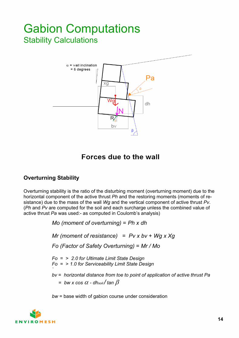
Gabion ComputationsStability Calculations
Overturning Stability
Overturning stability is the ratio of the disturbing moment (overturning moment) due to the horizontal component of the active thrust Ph and the restoring moments (moments of re-sistance) due to the mass of the wall Wg and the vertical component of active thrust Pv.(Ph and Pv are computed for the soil and each surcharge unless the combined value of active thrust Pa was used:- as computed in Coulomb’s analysis)
Mo (moment of overturning) = Ph x dh
Mr (moment of resistance) = Pv x bv + Wg x Xg
Fo (Factor of Safety Overturning) = Mr / Mo
Fo = > 2.0 for Ultimate Limit State Design Fo = > 1.0 for Serviceability Limit State Design
`bv = horizontal distance from toe to point of application of active thrust Pa
= bw x cos - dhsoil / tan
bw = base width of gabion course under consideration
14
Gabion ComputationsStability Calculations
Sliding Stability
Sliding Stability is the ratio of the forces resisting sliding (due to the mass of the gabions Wg and the vertical component of active thrust Pv) and the disturbing forces (due to the horizontal component of active thrust moment Ph ) on the plane of sliding.
N (normal force on plane of sliding) = Wg + Pv
T (tangential force on plane of sliding) = Ph
Fs (Factor of Safety Sliding)
= ( N cos T sin tan des (founding soil)____________________________________________________
(T cos sin
Fs = > 1.5 for Ultimate Limit State Design Fs = > 1.0 for Serviceability Limit State Design
Bearing Capacity
The loading on the founding soil must not exceed its allowable bearing capacity. The resultant load is normally eccentric to the centre of the base. Good design practice is to equalise the toe and heel pressures as much as possible either by stepping the gabions or by the inclination of the wall, but do not exceed 6 degrees for standard gabion 39 system or 10 degrees for gabion 27 system.
e (eccentricity of result on the base) = B/2 – ( Mr – Mo) / N
e <= B/6 (resultant must lie within the middle third of the base)
(bearing pressure on base) = N / B (1+ 6e/B) at the toe
(bearing pressure on base) = N / B (1- 6e/B) at the heel
<= allowable bearing capacity of the soil
15
Gabion ComputationsDesign Criteria and Gabion DensitiesDesign Criteria
A design check must be carried out for each course. The frictional value of gabion to gabion interface is taken as 35 degrees based on actual tests undertaken.
Factor of safety against overturning >2.0Factor of safety against sliding >1.5
In the case of a factor of safety of sliding on the sub grade which is within the range of 1.3 to 1.5, then the wall can founded on a granular sub base of minimum 300mm thick to improve sliding resistance. Re-evaluate the factor of safety on sliding with the phi value for a granular material to see if its above the required minimum factor of safety of 1.5. If not then the design section of the wall should be increased.
Stability can be improved by backfilling behind the wall with granular material.
If the cut slope is 45 degrees or less, then the wall is designed as if it is retaining a granular fill.
If the cut slope is 45 to 90 degrees, then the wall is designed on the existing soils. However the wall friction can be increased to 34 degrees in the evaluation of the vertical and horizontal components of active thrust.
Eccentricity (e) must fall within the mid third of the base width of the gabion.
The maximum bearing pressures computed must be less than the allowable for theunderlying soil.
Gabion Densities
Below are given the typical design densities for various types of gabion fill material:
Flint rejects and whole stone 14.5 kN/cumCrushed Concrete 15 kN/cumSandstone 15.5 kN/cumLimestone 16 kN/cumGranite 17 kN/cumBasalt 18 kN/cumAggregate fill 16 kN/cum (geotextile lined units)
16

Gabion ComputationsComplex Crest Profiles
Where the retained surface profile is complex, Coulomb’s Analysis cannot be used unless it is rationalised to a single slope.
The following method is an approximation of dealing with the complex condition.
In the above diagram, the wall is subject to two surcharge loadings - po1 and po2 together with two slopes.
To evaluate this condition, the Coulomb failure plane is drawn until it intersects the free surface. A line is then drawn from the intersection to the rear of the wall at the crest. The angle this makes with the horizontal is then the value of the slope used in the analysis ( equiv).
A line is then drawn parallel to the apex of the triangle above it, the perpendicular is measured (hs), this height is equivalent to a surcharge of soil on the assumed slope. This surcharge is then calculated:-
po assumed = hpo / soil
po design = po1 + po assumed or po2 whichever is the greater
17
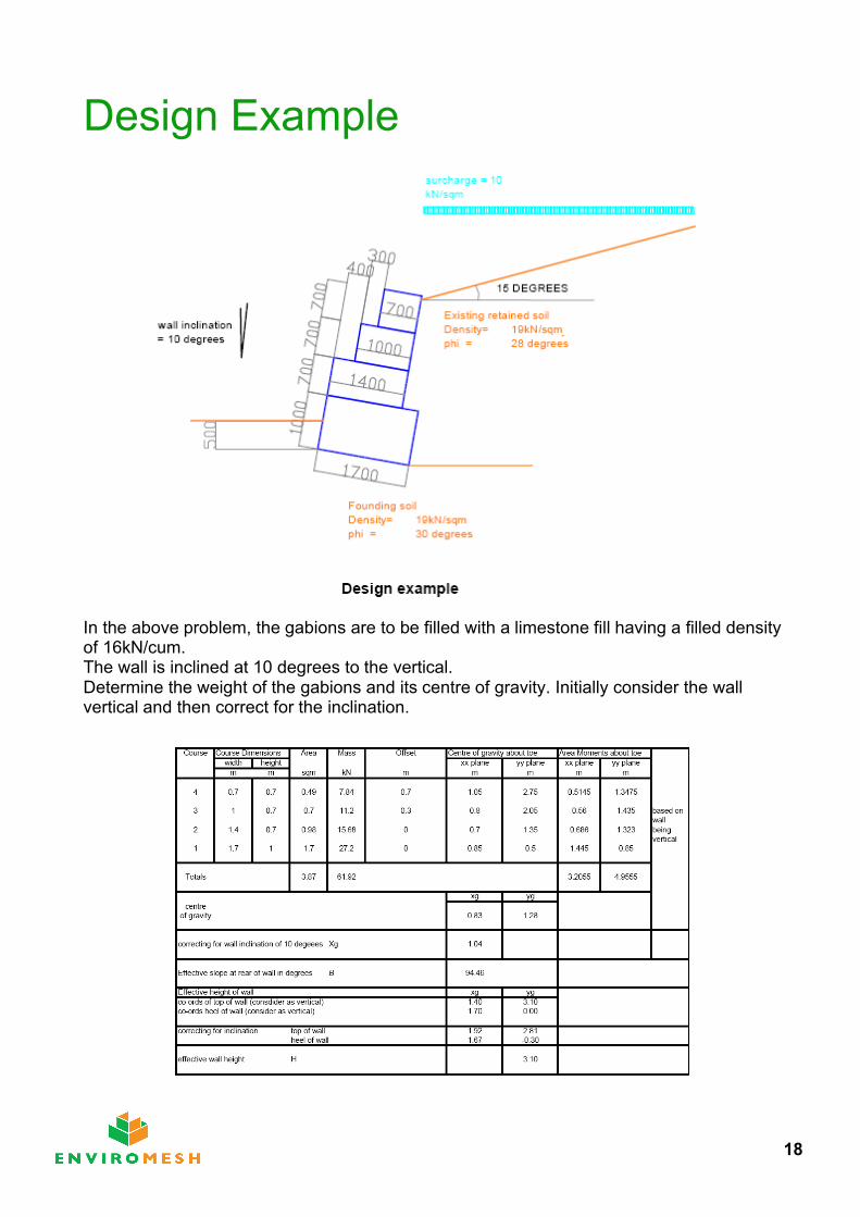
Design Example
In the above problem, the gabions are to be filled with a limestone fill having a filled density of 16kN/cum.The wall is inclined at 10 degrees to the vertical.Determine the weight of the gabions and its centre of gravity. Initially consider the wall vertical and then correct for the inclination.
18
22
2
)()()()(1
nisnisnisnisnisnis
nisak
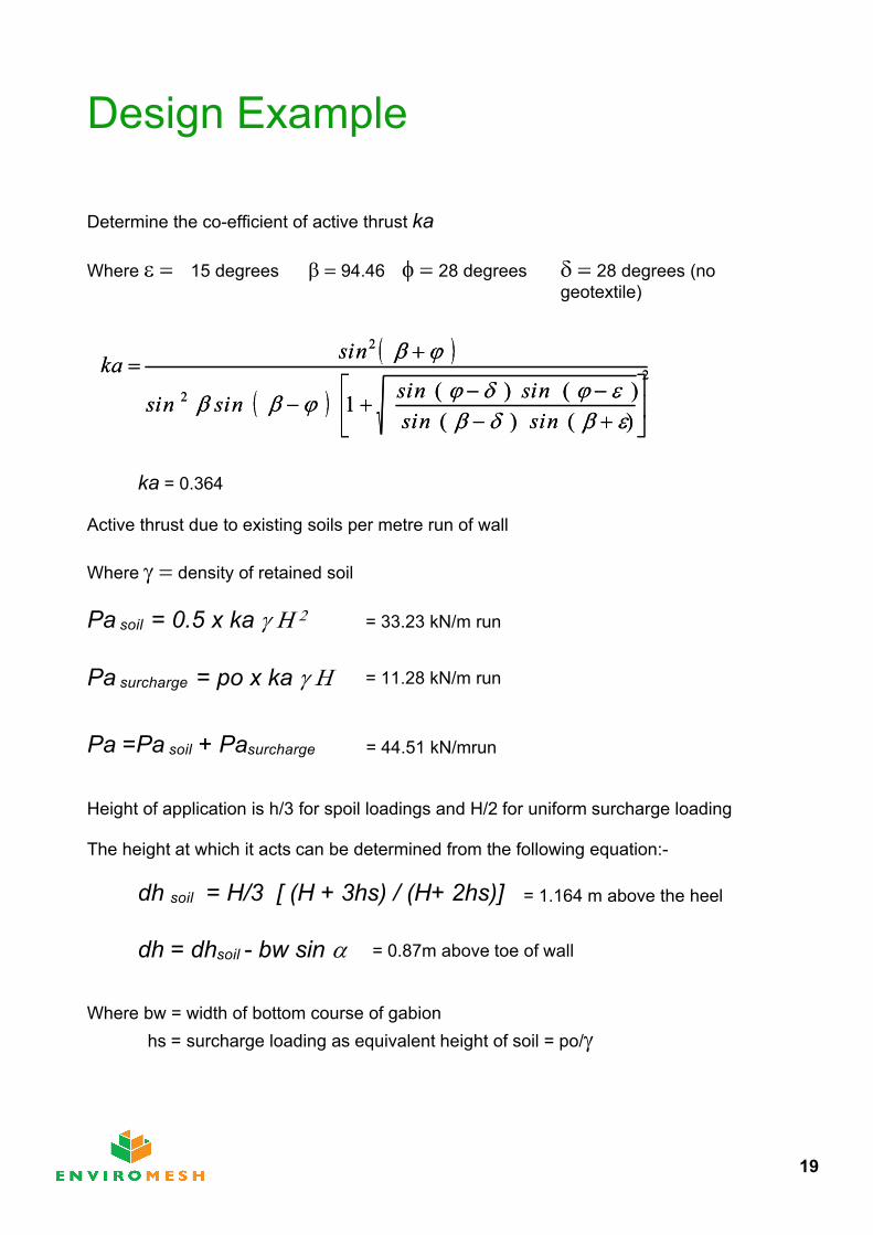
Design Example
Determine the co-efficient of active thrust ka
Where 15 degrees 94.46 28 degrees 28 degrees (no geotextile)
22
2
)()()()(1
nisnisnisnisnisnis
nisak
ka = 0.364
Active thrust due to existing soils per metre run of wall
Where density of retained soil
Pa soil = 0.5 x ka
Pa surcharge = po x ka
Pa =Pa soil + Pasurcharge
Height of application is h/3 for spoil loadings and H/2 for uniform surcharge loading
The height at which it acts can be determined from the following equation:-
dh soil = H/3 [ (H + 3hs) / (H+ 2hs)]
dh = dhsoil - bw sin
Where bw = width of bottom course of gabionhs = surcharge loading as equivalent height of soil = po/
= 33.23 kN/m run
= 11.28 kN/m run
= 44.51 kN/mrun
= 1.164 m above the heel
= 0.87m above toe of wall
19
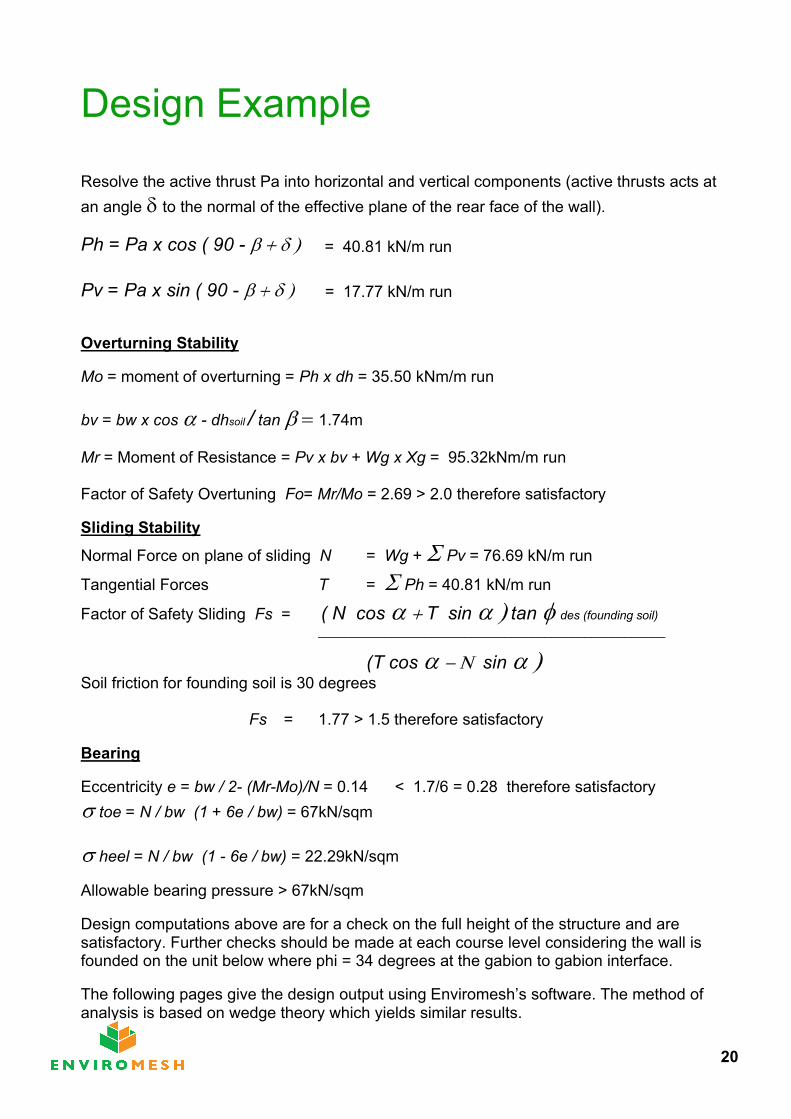
Design Example
Resolve the active thrust Pa into horizontal and vertical components (active thrusts acts at an angle to the normal of the effective plane of the rear face of the wall).
Ph = Pa x cos ( 90 -
Pv = Pa x sin ( 90 -
Overturning Stability
Mo = moment of overturning = Ph x dh = 35.50 kNm/m run
bv = bw x cos - dhsoil / tan 1.74m
Mr = Moment of Resistance = Pv x bv + Wg x Xg = 95.32kNm/m run
Factor of Safety Overtuning Fo= Mr/Mo = 2.69 > 2.0 therefore satisfactory
Sliding Stability
Normal Force on plane of sliding N = Wg + Pv = 76.69 kN/m run
Tangential Forces T = Ph = 40.81 kN/m run
Factor of Safety Sliding Fs = ( N cos T sin tan des (founding soil)____________________________________________________
(T cos sin Soil friction for founding soil is 30 degrees
Fs = 1.77 > 1.5 therefore satisfactory
Bearing
Eccentricity e = bw / 2- (Mr-Mo)/N = 0.14 < 1.7/6 = 0.28 therefore satisfactorytoe = N / bw (1 + 6e / bw) = 67kN/sqm
heel = N / bw (1 - 6e / bw) = 22.29kN/sqm
Allowable bearing pressure > 67kN/sqm
Design computations above are for a check on the full height of the structure and aresatisfactory. Further checks should be made at each course level considering the wall is founded on the unit below where phi = 34 degrees at the gabion to gabion interface.
The following pages give the design output using Enviromesh’s software. The method of analysis is based on wedge theory which yields similar results.
= 40.81 kN/m run
= 17.77 kN/m run
20

Retaining Wall Design Proposal Project Reference:- MAN -01
Project Title:- DESIGN CHECK
This design proposal is based exclusively on the use of ENVIROMESH'S materials installed in accordance with the manufacturer's instructions.
Whilst every care has been taken in producing this design proposal, it is the customers's responsibility to satisfy himself that the design, analysis and
specifications are correct. No responsibility is accepted by Cerana Limited for the accuracy of the design and specifications included in this proposal.
This design is the copyright of CERANA LIMITED., All rights reserved. No copying, reproduction or storage of this design in any form
is permitted without the written permission of CERANA LIMITED.
y axis
x axis
Ultimate Limit State Design
10 kN/sqm
Wall inclination = 10 deg
1.7m x 1m
1.4m x 0.7m
0.40 m1m x 0.7m
0.30 m0.7m x 0.7m
0.70 m
MAN - 01 22/02/2007
CAD Design Example
21
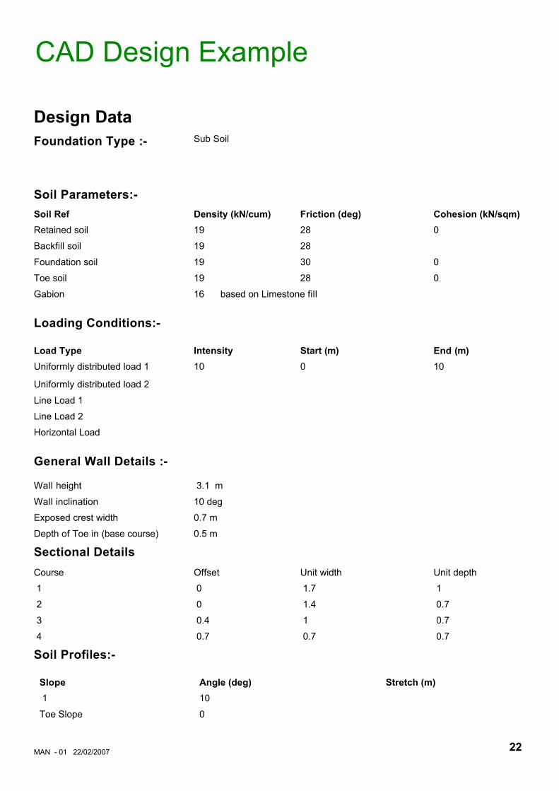
Design DataFoundation Type :- Sub Soil
Soil Parameters:-Soil Ref Density (kN/cum) Friction (deg) Cohesion (kN/sqm) Retained soil 19 28 0
Backfill soil 19 28
Foundation soil 19 30 0
Toe soil 19 28 0
Gabion 16 based on Limestone fill
Loading Conditions:-
Load Type Intensity Start (m) End (m) Uniformly distributed load 1 10 0 10
Uniformly distributed load 2
Line Load 1
Line Load 2
Horizontal Load
General Wall Details :-
Wall height 3.1 m
Wall inclination 10 deg
Exposed crest width 0.7 m
Depth of Toe in (base course) 0.5 m
Sectional DetailsCourse Offset Unit width Unit depth
1 0 1.7 1
2 0 1.4 0.7
3 0.4 1 0.7
4 0.7 0.7 0.7
Soil Profiles:-
Slope Angle (deg) Stretch (m) 1 10
Toe Slope 0
CAD Design Example
MAN - 01 22/02/2007 22
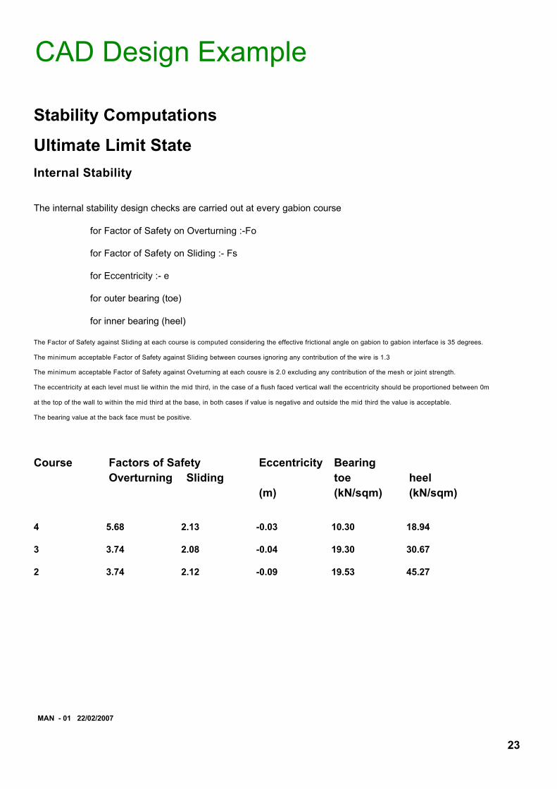
Stability Computations
Ultimate Limit StateInternal Stability
The internal stability design checks are carried out at every gabion course
for Factor of Safety on Overturning :-Fo
for Factor of Safety on Sliding :- Fs
for Eccentricity :- e
for outer bearing (toe)
for inner bearing (heel)
The Factor of Safety against Sliding at each course is computed considering the effective frictional angle on gabion to gabion interface is 35 degrees.
The minimum acceptable Factor of Safety against Sliding between courses ignoring any contribution of the wire is 1.3
The minimum acceptable Factor of Safety against Oveturning at each cousre is 2.0 excluding any contribution of the mesh or joint strength.
The eccentricity at each level must lie within the mid third, in the case of a flush faced vertical wall the eccentricity should be proportioned between 0m
at the top of the wall to within the mid third at the base, in both cases if value is negative and outside the mid third the value is acceptable.
The bearing value at the back face must be positive.
Course Factors of Safety Eccentricity BearingOverturning Sliding toe heel
(m) (kN/sqm) (kN/sqm)
4 5.68 2.13 -0.03 10.30 18.94
3 3.74 2.08 -0.04 19.30 30.67
2 3.74 2.12 -0.09 19.53 45.27
MAN - 01 22/02/2007
CAD Design Example
23
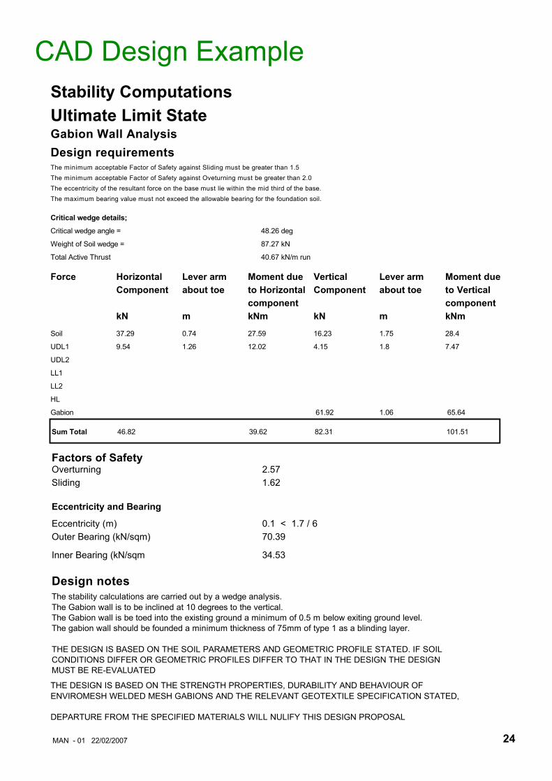
CAD Design ExampleStability ComputationsUltimate Limit StateGabion Wall AnalysisDesign requirementsThe minimum acceptable Factor of Safety against Sliding must be greater than 1.5The minimum acceptable Factor of Safety against Oveturning must be greater than 2.0The eccentricity of the resultant force on the base must lie within the mid third of the base.The maximum bearing value must not exceed the allowable bearing for the foundation soil.
Critical wedge details;
Critical wedge angle = 48.26 deg
Weight of Soil wedge = 87.27 kN
Total Active Thrust 40.67 kN/m run
Force Horizontal Lever arm Moment due Vertical Lever arm Moment due Component about toe to Horizontal Component about toe to Vertical
component component kN m kNm kN m kNm
Soil 37.29 0.74 27.59 16.23 1.75 28.4
UDL1 9.54 1.26 12.02 4.15 1.8 7.47
UDL2
LL1
LL2
HL
Gabion 61.92 1.06 65.64
Sum Total 46.82 39.62 82.31 101.51
Factors of Safety Overturning 2.57Sliding 1.62
Eccentricity and Bearing
Eccentricity (m) 0.1 < 1.7 / 6Outer Bearing (kN/sqm) 70.39
Inner Bearing (kN/sqm 34.53
Design notesThe stability calculations are carried out by a wedge analysis.The Gabion wall is to be inclined at 10 degrees to the vertical.The Gabion wall is be toed into the existing ground a minimum of 0.5 m below exiting ground level.The gabion wall should be founded a minimum thickness of 75mm of type 1 as a blinding layer.
THE DESIGN IS BASED ON THE SOIL PARAMETERS AND GEOMETRIC PROFILE STATED. IF SOIL CONDITIONS DIFFER OR GEOMETRIC PROFILES DIFFER TO THAT IN THE DESIGN THE DESIGNMUST BE RE-EVALUATED
THE DESIGN IS BASED ON THE STRENGTH PROPERTIES, DURABILITY AND BEHAVIOUR OF ENVIROMESH WELDED MESH GABIONS AND THE RELEVANT GEOTEXTILE SPECIFICATION STATED,
DEPARTURE FROM THE SPECIFIED MATERIALS WILL NULIFY THIS DESIGN PROPOSAL
MAN - 01 22/02/2007 24

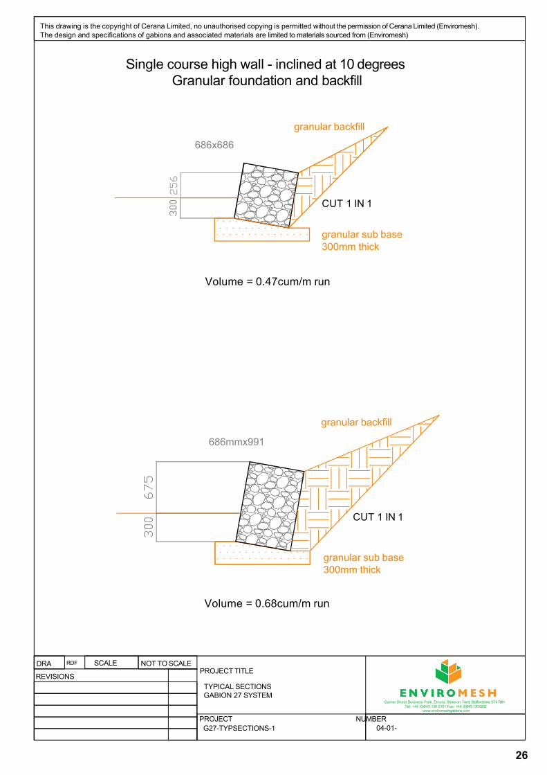
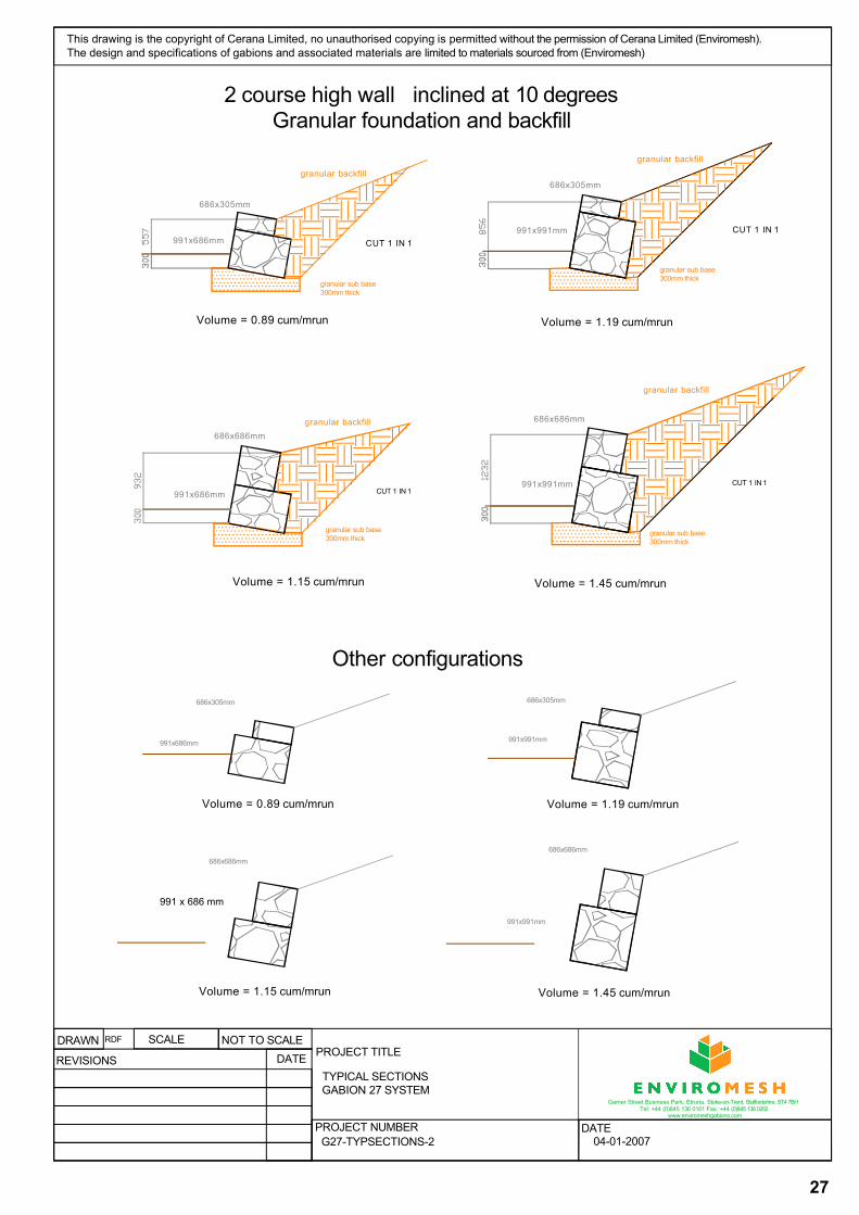
Typical Gabion SectionsGabion 27 System and Gabion 39 System
Typical detailed sections are illustrated for various wall configurations from 1 to 4 courses high.
The full sectional details given, have been dimensioned to show the retained heights with a considered toe in of 300mm.
The sections drawn are based on the wall being founded on a granular material. The backfill is also of a granular material cut back to a line of 45 degrees. These typical sections can only be used as a basis for estimating, unless the founding and backfill materials are as described above, the surcharge does not exceed 10kN/sqm on the retained fill slope of 0 to 15 degrees, and does not exceed 5 kN/sqm on retained slopes of 15 to 34 degrees.
The slope above the wall cannot exceed the internal angle of friction of the backfill.
It is recommended that an applicable soil investigation survey is undertaken and that the wall is designed by a suitably qualified competent engineer.
Other configurations of coursing of gabions are given, however the retained heights will differ due to the varying stepping arrangements on each course.
NOTE:-
No liability is accepted by Cerana Limited (Enviromesh) where a typical section as a basis for the final design is used. The details provided are guidelines only.
25
26
granular sub base 300mm thick
Volume = 0.68cum/m run
granular sub base 300mm thick
686x686
granular backfill
686mmx991
granular backfill
Volume = 0.47cum/m run
CUT 1 IN 1
CUT 1 IN 1
DRAPROJECT TITLE
PROJECT NUMBER
RDF SCALE NOT TO SCALE
REVISIONS
This drawing is the copyright of Cerana Limited, no unauthorised copying is permitted without the permission of Cerana Limited (Enviromesh). The design and specifications of gabions and associated materials are limited to materials sourced from (Enviromesh)
TYPICAL SECTIONSGABION 27 SYSTEM
G27-TYPSECTIONS-1 04-01-
Garner Street Business Park, Etruria, Stoke-on-Trent, Staffordshire, ST4 7BH Tel: +44 (0)845 136 0101 Fax: +44 (0)845 136 0202
www.enviromeshgabions.com
Single course high wall - inclined at 10 degrees Granular foundation and backfill
27
991 x 686 mm
686x686mm
686x305mm
991x686mm
991x686mm
Volume = 1.19 cum/mrun
686x305mm
991x991mm
granular backfill
Volume = 0.89 cum/mrun
granular backfill
granular backfill
Volume = 1.15 cum/mrun
granular sub base 300mm thick
Volume = 1.45 cum/mrun
686x686mm
991x991mm
granular backfill
686x686mm
686x305mm
991x686mm
Volume = 1.19 cum/mrun
686x305mm
991x991mm
Volume = 0.89 cum/mrun
Volume = 1.15 cum/mrun Volume = 1.45 cum/mrun
686x686mm
991x991mm
CUT 1 IN 1CUT 1 IN 1
CUT 1 IN 1CUT 1 IN 1
granular sub base300mm thick
granular sub base300mm thick
granular sub base 300mm thick
PROJECT TITLE
PROJECT NUMBER DATE
DRAWN RDF SCALE NOT TO SCALE
REVISIONS DATETYPICAL SECTIONSGABION 27 SYSTEM
G27-TYPSECTIONS-2 04-01-2007
Garner Street Business Park, Etruria, Stoke-on-Trent, Staffordshire, ST4 7BH Tel: +44 (0)845 136 0101 Fax: +44 (0)845 136 0202
www.enviromeshgabions.com
2 course high wall inclined at 10 degrees Granular foundation and backfill
This drawing is the copyright of Cerana Limited, no unauthorised copying is permitted without the permission of Cerana Limited (Enviromesh). The design and specifications of gabions and associated materials are limited to materials sourced from (Enviromesh)
Other configurations
28
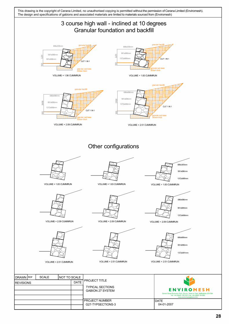
granular sub base 300mm thick
VOLUME = 1.83 CUM/MRUN
991x686mm
686x305mmgranular backfill
1372x686mm
granular sub base 300mm thick
991x686mm
686x305mm granular backfill
991x686mm
VOLUME = 1.56 CUM/MRUN
granular sub base 300mm thick
VOLUME = 2.51 CUM/MRUN
991x686mm
686x686mm
granular backfill
1372x686mm
granular sub base 300mm thick
VOLUME = 2.09 CUM/MRUN
991x686mm
686x686mm
granular backfill
1372x686mm
686x305mm
991x686mm
1372x686mm
686x686mm
991x686mm
1372x686mm
686x686mm
991x686mm
1372x991mm
CUT 1 IN 1CUT 1 IN 1
CUT 1 IN 1
CUT 1 IN 1
VOLUME = 1.83 CUM/MRUN VOLUME = 1.83 CUM/MRUN VOLUME = 1.83 CUM/MRUN
VOLUME = 2.09 CUM/MRUN VOLUME = 2.09 CUM/MRUN VOLUME = 2.09 CUM/MRUN
VOLUME = 2.51 CUM/MRUN VOLUME = 2.51 CUM/MRUN VOLUME = 2.51 CUM/MRUN
PROJECT TITLE
PROJECT NUMBER DATE
DRAWN RDF SCALE NOT TO SCALE
REVISIONS DATETYPICAL SECTIONSGABION 27 SYSTEM
G27-TYPSECTIONS-3 04-01-2007
3 course high wall - inclined at 10 degrees Granular foundation and backfill
This drawing is the copyright of Cerana Limited, no unauthorised copying is permitted without the permission of Cerana Limited (Enviromesh). The design and specifications of gabions and associated materials are limited to materials sourced from (Enviromesh)
Garner Street Business Park, Etruria, Stoke-on-Trent, Staffordshire, ST4 7BH Tel: +44 (0)845 136 0101 Fax: +44 (0)845 136 0202
www.enviromeshgabions.com
Other configurations
29
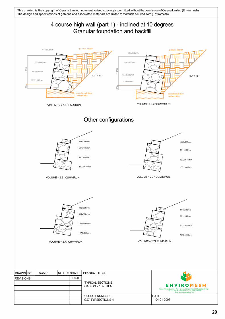
granular sub base 300mm thick
VOLUME = 2.77 CUM/MRUN
991x686mm
686x305mm
granular backfill
1372x686mm
granular sub base 300mm thick
991x686mm
686x305mm granular backfill
991x686mm
VOLUME = 2.51 CUM/MRUN
1372x686mm1372x686mm
CUT 1 IN 1 CUT 1 IN 1
686x305mm
991x686mm
1372x686mm
1372x686mm
686x305mm
991x686mm
1372x686mm
1372x686mm
VOLUME = 2.51 CUM/MRUN VOLUME = 2.77 CUM/MRUN
VOLUME = 2.77 CUM/MRUN VOLUME = 2.77 CUM/MRUN
686x305mm
991x686mm
1372x686mm
1372x686mm
686x305mm
991x686mm
991x686mm
1372x686mm
PROJECT TITLE
PROJECT NUMBER DATE
DRAWN RDF SCALE NOT TO SCALE
REVISIONS DATETYPICAL SECTIONSGABION 27 SYSTEM
G27-TYPSECTIONS-4 04-01-2007
4 course high wall (part 1) - inclined at 10 degrees Granular foundation and backfill
This drawing is the copyright of Cerana Limited, no unauthorised copying is permitted without the permission of Cerana Limited (Enviromesh). The design and specifications of gabions and associated materials are limited to materials sourced from (Enviromesh)
Garner Street Business Park, Etruria, Stoke-on-Trent, Staffordshire, ST4 7BH Tel: +44 (0)845 136 0101 Fax: +44 (0)845 136 0202
www.enviromeshgabions.com
Other configurations
30
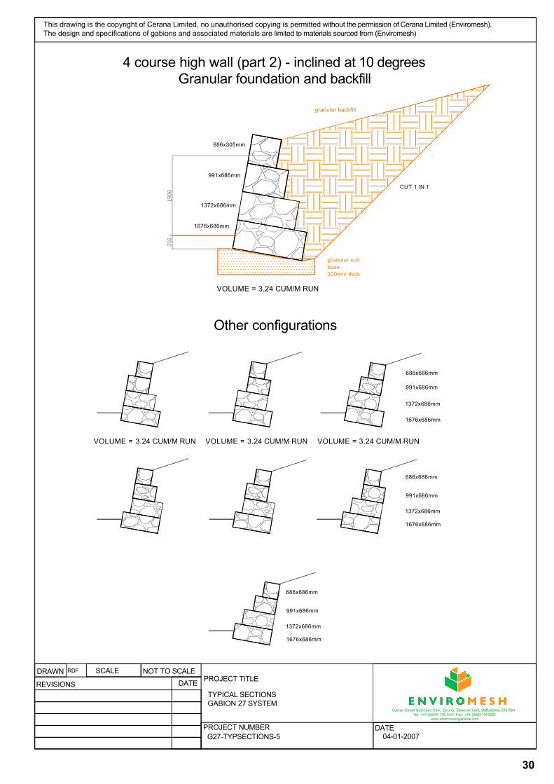
granular sub base300mm thick
VOLUME = 3.24 CUM/M RUN
991x686mm
686x305mm
granular backfill
1372x686mm
1676x686mm
CUT 1 IN 1
991x686mm
1372x686mm
1676x686mm
686x686mm
991x686mm
1372x686mm
1676x686mm
686x686mm
991x686mm
1372x686mm
1676x686mm
686x686mm
VOLUME = 3.24 CUM/M RUN VOLUME = 3.24 CUM/M RUN VOLUME = 3.24 CUM/M RUN
PROJECT TITLE
PROJECT NUMBER DATE
DRAWN RDF SCALE NOT TO SCALE
REVISIONS DATETYPICAL SECTIONSGABION 27 SYSTEM
G27-TYPSECTIONS-5 04-01-2007
This drawing is the copyright of Cerana Limited, no unauthorised copying is permitted without the permission of Cerana Limited (Enviromesh). The design and specifications of gabions and associated materials are limited to materials sourced from (Enviromesh)
Garner Street Business Park, Etruria, Stoke-on-Trent, Staffordshire, ST4 7BH Tel: +44 (0)845 136 0101 Fax: +44 (0)845 136 0202
www.enviromeshgabions.com
4 course high wall (part 2) - inclined at 10 degrees Granular foundation and backfill
Other configurations
31
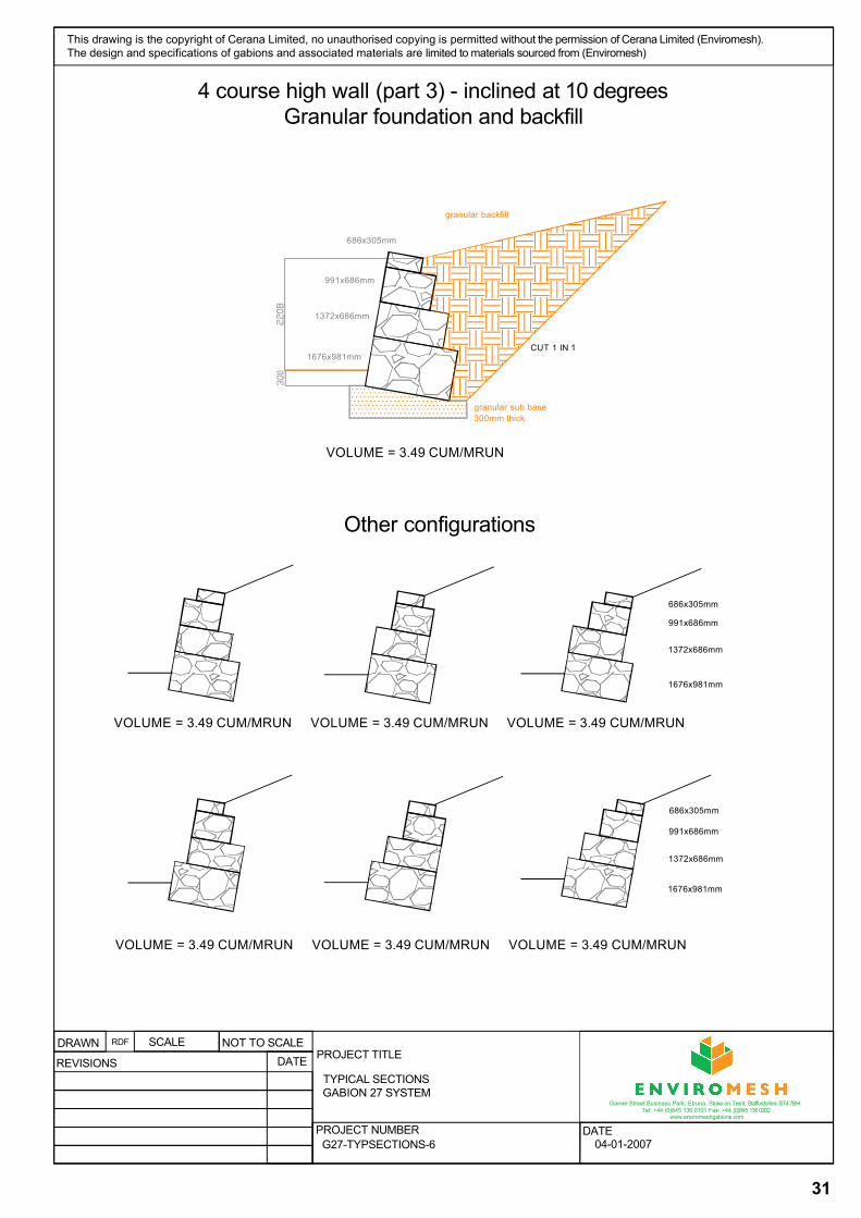
granular sub base 300mm thick
VOLUME = 3.49 CUM/MRUN
991x686mm
granular backfill
1372x686mm
CUT 1 IN 11676x981mm
686x305mm
686x305mm
991x686mm
1372x686mm
1676x981mm
686x305mm
991x686mm
1372x686mm
1676x981mm
VOLUME = 3.49 CUM/MRUN VOLUME = 3.49 CUM/MRUN VOLUME = 3.49 CUM/MRUN
VOLUME = 3.49 CUM/MRUN VOLUME = 3.49 CUM/MRUN VOLUME = 3.49 CUM/MRUN
PROJECT TITLE
PROJECT NUMBER DATE
DRAWN RDF SCALE NOT TO SCALE
REVISIONS DATETYPICAL SECTIONSGABION 27 SYSTEM
G27-TYPSECTIONS-6 04-01-2007
This drawing is the copyright of Cerana Limited, no unauthorised copying is permitted without the permission of Cerana Limited (Enviromesh). The design and specifications of gabions and associated materials are limited to materials sourced from (Enviromesh)
Garner Street Business Park, Etruria, Stoke-on-Trent, Staffordshire, ST4 7BH Tel: +44 (0)845 136 0101 Fax: +44 (0)845 136 0202
www.enviromeshgabions.com
4 course high wall (part 3) - inclined at 10 degrees Granular foundation and backfill
Other configurations
32
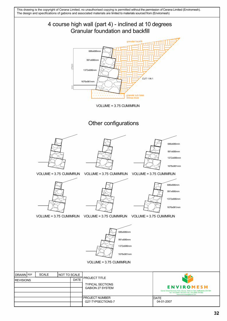
granular sub base 300mm thick
VOLUME = 3.75 CUM/MRUN
991x686mm
686x686mm
granular backfill
1372x686mm
CUT 1 IN 11676x981mm
686x686mm
991x686mm
1372x686mm
1676x981mm
686x686mm
991x686mm
1372x686mm
1676x981mm
VOLUME = 3.75 CUM/MRUN VOLUME = 3.75 CUM/MRUN VOLUME = 3.75 CUM/MRUN
VOLUME = 3.75 CUM/MRUN VOLUME = 3.75 CUM/MRUN VOLUME = 3.75 CUM/MRUN
VOLUME = 3.75 CUM/MRUN
686x686mm
991x686mm
1372x686mm
1676x981mm
PROJECT TITLE
PROJECT NUMBER DATE
DRAWN RDF SCALE NOT TO SCALE
REVISIONS DATETYPICAL SECTIONSGABION 27 SYSTEM
G27-TYPSECTIONS-7 04-01-2007
4 course high wall (part 4) - inclined at 10 degrees Granular foundation and backfill
Garner Street Business Park, Etruria, Stoke-on-Trent, Staffordshire, ST4 7BH Tel: +44 (0)845 136 0101 Fax: +44 (0)845 136 0202
www.enviromeshgabions.com
Other configurations
This drawing is the copyright of Cerana Limited, no unauthorised copying is permitted without the permission of Cerana Limited (Enviromesh). The design and specifications of gabions and associated materials are limited to materials sourced from (Enviromesh)

33
granular sub base 300mm thick
1mx1mgranular backfill
Volume =1.0cum/m run
CUT 1 IN 1
granular sub base 300mm thick
granular backfill
Volume =1.5cum/m run
CUT 1 IN 1
granular sub base 300mm thick
1.5mx1m
granular backfill
Volume =2.0cum/m run
CUT 1 IN 1
1mx0.5m
granular sub base 300mm thick
1.5mx0.5m
granular backfill
Volume =1.75cum/m run
CUT 1 IN 1
1mx1mm
NOTES :_
Retained height dimensions are indicative, true dimensions are dependant on whichtype of gabion is specified , welded mesh or woven mesh
Offset on each gabion course can vary from 0 to max offset possible without gabionsoverhanging unit below
granular sub base 300mm thick
1.5mx1m
granular backfill
Volume =2.5cum/m run
CUT 1 IN 1
1mx1m
1.5mx1m
1mx1m
1mx1m
1.5mx0.5m1.5mx1m
1mx0.5m
1mx1m
Volume =2.0cum/m run Volume =1.75cum/m run Volume =1.75cum/m run
DRAWNPROJECT TITLE
PROJECT NUMBER DATE
RDF SCALE NOT TO SCALE
REVISIONS DATETYPICAL SECTIONSSTANDARD GABION 29 SYSTEM
G39-TYPSECTIONS-1 04-01-2007
2 course high wall - inclined at 6 degrees Granular backfiil and foundation
Single course high wall - inclined at 6 degrees Granular backfiil and foundation
Other configurations
Garner Street Business Park, Etruria, Stoke-on-Trent, Staffordshire, ST4 7BH Tel: +44 (0)845 136 0101 Fax: +44 (0)845 136 0202
www.enviromeshgabions.com
This drawing is the copyright of Cerana Limited, no unauthorised copying is permitted without the permission of Cerana Limited (Enviromesh). The design and specifications of gabions and associated materials are limited to materials sourced from (Enviromesh)
34
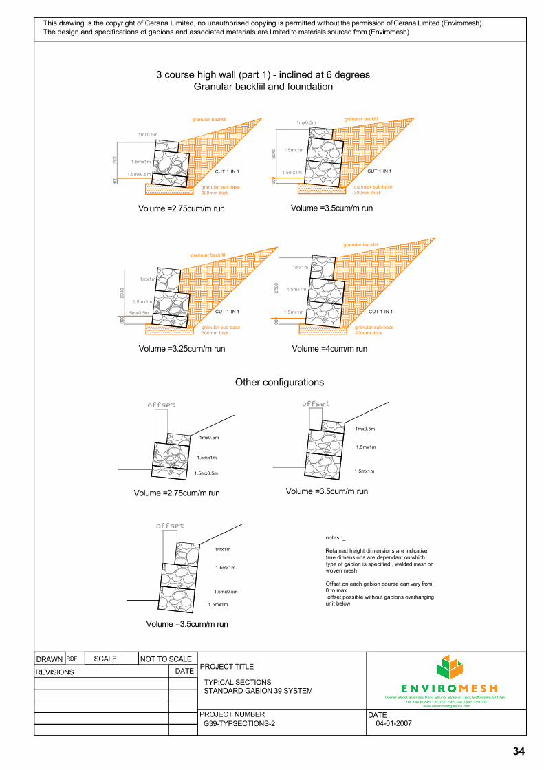
granular sub base 300mm thick
1.5mx1m
granular backfill
Volume =3.5cum/m run
CUT 1 IN 1
1mx0.5m
1.5mx1m
granular sub base 300mm thick
1.5mx0.5m
granular backfill
Volume =2.75cum/m run
CUT 1 IN 1
1mx0.5m
1.5mx1m
granular sub base 300mm thick
1.5mx1m
granular backfill
Volume =4cum/m run
CUT 1 IN 1
1.5mx1m
1mx1m
granular sub base 300mm thick
1.5mx0.5m
granular backfill
Volume =3.25cum/m run
CUT 1 IN 1
1.5mx1m
1mx1m
1mx1m
1.5mx1m
1.5mx0.5m
1mx0.5m
1.5mx1m
1.5mx1m
1mx0.5m
1.5mx1m
1.5mx0.5m
Volume =2.75cum/m run Volume =3.5cum/m run
1.5mx1m
Volume =3.5cum/m run
notes :_
Retained height dimensions are indicative, true dimensions are dependant on whichtype of gabion is specified , welded mesh or woven mesh
Offset on each gabion course can vary from 0 to maxoffset possible without gabions overhanging
unit below
PROJECT TITLE
PROJECT NUMBER DATE
DRAWN RDF SCALE NOT TO SCALE
REVISIONS DATETYPICAL SECTIONSSTANDARD GABION 39 SYSTEM
G39-TYPSECTIONS-2 04-01-2007
Garner Street Business Park, Etruria, Stoke-on-Trent, Staffordshire, ST4 7BH Tel: +44 (0)845 136 0101 Fax: +44 (0)845 136 0202
www.enviromeshgabions.com
3 course high wall (part 1) - inclined at 6 degrees Granular backfiil and foundation
Other configurations
This drawing is the copyright of Cerana Limited, no unauthorised copying is permitted without the permission of Cerana Limited (Enviromesh). The design and specifications of gabions and associated materials are limited to materials sourced from (Enviromesh)
35
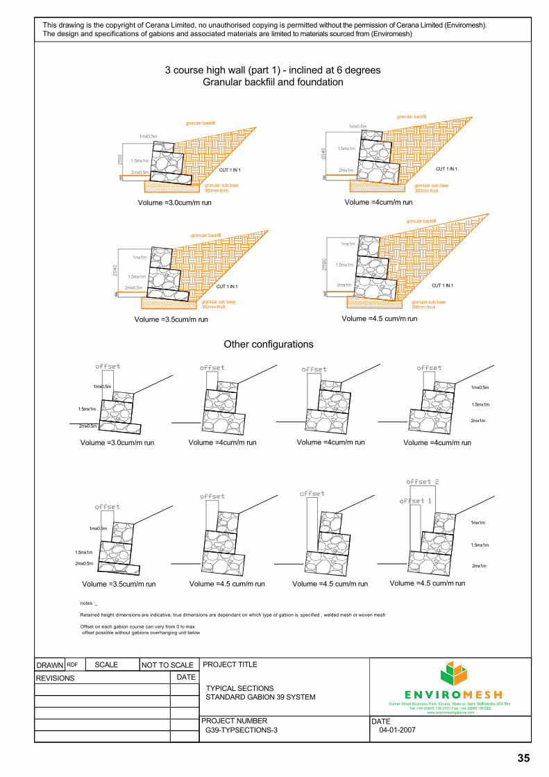
granular sub base 300mm thick
2mx1m
granular backfill
Volume =4cum/m run
CUT 1 IN 1
1mx0.5m
1.5mx1m
granular sub base 300mm thick
2mx0.5m
granular backfill
Volume =3.0cum/m run
CUT 1 IN 1
1mx0.5m
1.5mx1m
granular sub base 300mm thick
2mx1m
granular backfill
Volume =4.5 cum/m run
CUT 1 IN 1
1.5mx1m
granular sub base 300mm thick
2mx0.5m
granular backfill
Volume =3.5cum/m run
CUT 1 IN 1
1mx1m
1.5mx1m
1mx1m
1mx0.5m
1.5mx1m
2mx1m 2mx0.5m
2mx0.5m
1mx1m
1.5mx1m
2mx1m
1.5mx1m
1mx0.5m
Volume =3.0cum/m run Volume =4cum/m run Volume =4cum/m run Volume =4cum/m run
1.5mx1m
1mx0.5m
Volume =3.5cum/m run Volume =4.5 cum/m run Volume =4.5 cum/m run Volume =4.5 cum/m run
notes :_
Retained height dimensions are indicative, true dimensions are dependant on which type of gabion is specified , welded mesh or woven mesh
Offset on each gabion course can vary from 0 to maxoffset possible without gabions overhanging unit below
PROJECT TITLE
PROJECT NUMBER DATE
DRAWN RDF SCALE NOT TO SCALE
REVISIONS DATETYPICAL SECTIONSSTANDARD GABION 39 SYSTEM
G39-TYPSECTIONS-3 04-01-2007
This drawing is the copyright of Cerana Limited, no unauthorised copying is permitted without the permission of Cerana Limited (Enviromesh). The design and specifications of gabions and associated materials are limited to materials sourced from (Enviromesh)
Other configurations
3 course high wall (part 1) - inclined at 6 degrees Granular backfiil and foundation
Garner Street Business Park, Etruria, Stoke-on-Trent, Staffordshire, ST4 7BH Tel: +44 (0)845 136 0101 Fax: +44 (0)845 136 0202
www.enviromeshgabions.com
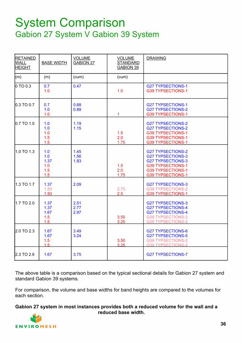
System ComparisonGabion 27 System V Gabion 39 System
RETAINED VOLUME VOLUME DRAWINGWALL BASE WIDTH GABION 27 STANDARDHEIGHT GABION 39
(m) (m) (cum) (cum)
0 TO 0.3 0.7 0.47 G27 TYPSECTIONS-11.0 1.0 G39 TYPSECTIONS-1
0.3 TO 0.7 0.7 0.68 G27 TYPSECTIONS-11.0 0.89 G27 TYPSECTIONS-21.0 1 G39 TYPSECTIONS-1
0.7 TO 1.0 1.0 1.19 G27 TYPSECTIONS-21.0 1.15 G27 TYPSECTIONS-21.0 1.5 G39 TYPSECTIONS-11.5 2.0 G39 TYPSECTIONS-11.5 1.75 G39 TYPSECTIONS-1
1.0 TO 1.3 1.0 1.45 G27 TYPSECTIONS-21.0 1.56 G27 TYPSECTIONS-31.37 1.83 G27 TYPSECTIONS-31.0 1.5 G39 TYPSECTIONS-11.5 2.0 G39 TYPSECTIONS-11.5 1.75 G39 TYPSECTIONS-1
1.3 TO 1.7 1.37 2.09 G27 TYPSECTIONS-31.50 2.75 G39 TYPSECTIONS-21.50 2.5 G39 TYPSECTIONS-1
1.7 TO 2.0 1.37 2.51 G27 TYPSECTIONS-31.37 2.77 G27 TYPSECTIONS-41.67 2.97 G27 TYPSECTIONS-41.5 3.50 G39 TYPSECTIONS-21.5 3.25 G39 TYPSECTIONS-2
2.0 TO 2.3 1.67 3.49 G27 TYPSECTIONS-61.67 3.24 G27 TYPSECTIONS-51.5 3.50 G39 TYPSECTIONS-21.5 3.25 G39 TYPSECTIONS-2
2.3 TO 2.6 1.67 3.75 G27 TYPSECTIONS-7
The above table is a comparison based on the typical sectional details for Gabion 27 system and standard Gabion 39 systems.
For comparison, the volume and base widths for band heights are compared to the volumes for each section.
Gabion 27 system in most instances provides both a reduced volume for the wall and a reduced base width.
36

SpecificationsIt is important to ensure that the correct specification is used for the gabions.
The following sheets give the specifications for:-
Welded Mesh Gabion 27 System
Welded Mesh Gabion 39 System
Hexagonal Woven Mesh Gabions
Where the gabions are subject to salt spray, saline water, acidic soils (out of range PH7 to 10) or brackish water, then PVC - Zinc coated hexagonal gabions should be specified.
For schemes where visual quality is not important, either woven or standard welded mesh gabions are acceptable.
For prestige schemes where the visual quality is important, the best specification is the Gabion 27 system.
37
Garner Street Business Park, Mercurial, Stoke-on-Trent, Staffordshire, ST4 7BHTel: +44 (0)845 136 0101 Fax: +44 (0)845 136 0202
www.enviromeshgabions.com
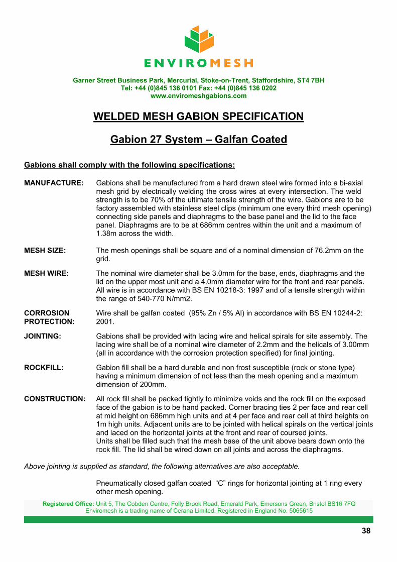
WELDED MESH GABION SPECIFICATION
Gabion 27 System – Galfan Coated
Gabions shall comply with the following specifications:
MANUFACTURE: Gabions shall be manufactured from a hard drawn steel wire formed into a bi-axial mesh grid by electrically welding the cross wires at every intersection. The weld strength is to be 70% of the ultimate tensile strength of the wire. Gabions are to be factory assembled with stainless steel clips (minimum one every third mesh opening) connecting side panels and diaphragms to the base panel and the lid to the face panel. Diaphragms are to be at 686mm centres within the unit and a maximum of 1.38m across the width.
MESH SIZE: The mesh openings shall be square and of a nominal dimension of 76.2mm on the grid.
MESH WIRE: The nominal wire diameter shall be 3.0mm for the base, ends, diaphragms and the lid on the upper most unit and a 4.0mm diameter wire for the front and rear panels. All wire is in accordance with BS EN 10218-3: 1997 and of a tensile strength within the range of 540-770 N/mm2.
CORROSION Wire shall be galfan coated (95% Zn / 5% Al) in accordance with BS EN 10244-2: PROTECTION: 2001.
JOINTING: Gabions shall be provided with lacing wire and helical spirals for site assembly. The lacing wire shall be of a nominal wire diameter of 2.2mm and the helicals of 3.00mm (all in accordance with the corrosion protection specified) for final jointing.
ROCKFILL: Gabion fill shall be a hard durable and non frost susceptible (rock or stone type) having a minimum dimension of not less than the mesh opening and a maximum dimension of 200mm.
CONSTRUCTION: All rock fill shall be packed tightly to minimize voids and the rock fill on the exposed face of the gabion is to be hand packed. Corner bracing ties 2 per face and rear cell at mid height on 686mm high units and at 4 per face and rear cell at third heights on 1m high units. Adjacent units are to be jointed with helical spirals on the vertical joints and laced on the horizontal joints at the front and rear of coursed joints.Units shall be filled such that the mesh base of the unit above bears down onto the rock fill. The lid shall be wired down on all joints and across the diaphragms.
Above jointing is supplied as standard, the following alternatives are also acceptable.
Pneumatically closed galfan coated “C” rings for horizontal jointing at 1 ring every other mesh opening.
38
Registered Office: Unit 5, The Cobden Centre, Folly Brook Road, Emerald Park, Emersons Green, Bristol BS16 7FQEnviromesh is a trading name of Cerana Limited. Registered in England No. 5065615
Garner Street Business Park, Etruria, Stoke-on-Trent, Staffordshire, ST4 7BHTel: +44 (0)845 136 0101 Fax: +44 (0)845 136 0202
www.enviromeshgabions.com
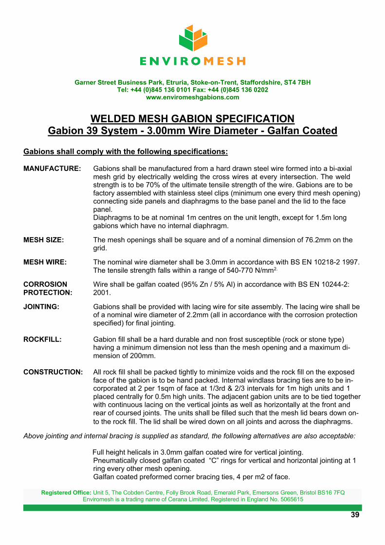
WELDED MESH GABION SPECIFICATIONGabion 39 System - 3.00mm Wire Diameter - Galfan Coated
Gabions shall comply with the following specifications:
MANUFACTURE: Gabions shall be manufactured from a hard drawn steel wire formed into a bi-axial mesh grid by electrically welding the cross wires at every intersection. The weld strength is to be 70% of the ultimate tensile strength of the wire. Gabions are to be factory assembled with stainless steel clips (minimum one every third mesh opening) connecting side panels and diaphragms to the base panel and the lid to the face panel.Diaphragms to be at nominal 1m centres on the unit length, except for 1.5m long gabions which have no internal diaphragm.
MESH SIZE: The mesh openings shall be square and of a nominal dimension of 76.2mm on the grid.
MESH WIRE: The nominal wire diameter shall be 3.0mm in accordance with BS EN 10218-2 1997. The tensile strength falls within a range of 540-770 N/mm2.
CORROSION Wire shall be galfan coated (95% Zn / 5% Al) in accordance with BS EN 10244-2:PROTECTION: 2001.
JOINTING: Gabions shall be provided with lacing wire for site assembly. The lacing wire shall be of a nominal wire diameter of 2.2mm (all in accordance with the corrosion protection specified) for final jointing.
ROCKFILL: Gabion fill shall be a hard durable and non frost susceptible (rock or stone type) having a minimum dimension not less than the mesh opening and a maximum di-mension of 200mm.
CONSTRUCTION: All rock fill shall be packed tightly to minimize voids and the rock fill on the exposed face of the gabion is to be hand packed. Internal windlass bracing ties are to be in-corporated at 2 per 1sqm of face at 1/3rd & 2/3 intervals for 1m high units and 1 placed centrally for 0.5m high units. The adjacent gabion units are to be tied together with continuous lacing on the vertical joints as well as horizontally at the front and rear of coursed joints. The units shall be filled such that the mesh lid bears down on-to the rock fill. The lid shall be wired down on all joints and across the diaphragms.
Above jointing and internal bracing is supplied as standard, the following alternatives are also acceptable:
Full height helicals in 3.0mm galfan coated wire for vertical jointing.Pneumatically closed galfan coated “C” rings for vertical and horizontal jointing at 1 ring every other mesh opening.Galfan coated preformed corner bracing ties, 4 per m2 of face.
39
Registered Office: Unit 5, The Cobden Centre, Folly Brook Road, Emerald Park, Emersons Green, Bristol BS16 7FQEnviromesh is a trading name of Cerana Limited. Registered in England No. 5065615

Garner Street Business Park, Etruria, Stoke-on-Trent, Staffordshire, ST4 7BHTel: +44 (0)845 136 0101 Fax: +44 (0)845 136 0202
www.enviromeshgabions.com
WELDED MESH GABION SPECIFICATIONGabion 39 System - 4.00mm Wire Diameter - Galfan Coated
Gabions shall comply with the following specifications:
MANUFACTURE: Gabions shall be manufactured from a hard drawn steel wire formed into a bi-axial mesh grid by electrically welding the cross wires at every intersection. The weld strength is to be 70% of the ultimate tensile strength of the wire. Gabions are to be factory assembled with stainless steel clips (minimum one every third mesh opening) connecting side panels and diaphragms to the base panel and the lid to the face panel.Diaphragms to be at nominal 1m centres on the unit length, except for 1.5m long gabions which have no internal diaphragm.
MESH SIZE: The mesh openings shall be square and of a nominal dimension of 76.2mm on the grid.
MESH WIRE: The nominal wire diameter shall be 4.0mm in accordance with BS EN 10218-2 1997. The tensile strength falls within a range of 540-770 N/mm2.
CORROSION Wire shall be galfan coated (95% Zn / 5% Al) in accordance with BS EN 10244-2:PROTECTION: 2001.
JOINTING: Gabions shall be provided with lacing wire for site assembly. The lacing wire shall be of a nominal wire diameter of 2.2mm (all in accordance with the corrosion protection specified) for final jointing.
ROCKFILL: Gabion fill shall be a hard durable and non frost susceptible (rock or stone type) having a minimum dimension not less than the mesh opening and a maximum dimension of 200mm.
CONSTRUCTION: All rock fill shall be packed tightly to minimize voids and the rock fill on the exposed face of the gabion is to be hand packed. Internal windlass bracing ties are to be in-corporated at 2 per 1sqm of face at 1/3rd & 2/3 intervals for 1m high units and 1 placed centrally for 0.5m high units. The adjacent gabion units are to be tied together with continuous lacing on the vertical joints as well as horizontally at the front and rear of coursed joints. The units shall be filled such that the mesh lid bears down on-to the rock fill. The lid shall be wired down on all joints and across the diaphragms.
Above jointing and internal bracing is supplied as standard, the following alternatives are also acceptable:
Full height helicals in 3.0mm galfan coated wire for vertical jointing.Pneumatically closed galfan coated “C” rings for vertical and horizontal jointing at 1 ring every other mesh opening.Galfan coated preformed corner bracing ties, 4 per m2 of face.
40
Registered Office: Unit 5, The Cobden Centre, Folly Brook Road, Emerald Park, Emersons Green, Bristol BS16 7FQEnviromesh is a trading name of Cerana Limited. Registered in England No. 5065615

Garner Street Business Park, Etruria, Stoke-on-Trent, Staffordshire, ST4 7BHTel: +44 (0)845 136 0101 Fax: +44 (0)845 136 0202
www.enviromeshgabions.com
WELDED MESH GABION SPECIFICATIONGabion 39 System - 3.00 / 4.00mm Wire Diameter - Galfan Coated
Gabions shall comply with the following specifications:
MANUFACTURE: Gabions shall be manufactured from a hard drawn steel wire formed into a bi-axial mesh grid by electrically welding the cross wires at every intersection. The weld strength is to be 70% of the ultimate tensile strength of the wire. Gabions are to be factory assembled with stainless steel clips (minimum one every third mesh opening) connecting side panels and diaphragms to the base panel and the lid to the face panel.Diaphragms to be at nominal 1m centres on the unit length, except for 1.5m long gabions which have no internal diaphragm.
MESH SIZE: The mesh openings shall be square and of a nominal dimension of 76.2mm on the grid.
MESH WIRE: The nominal wire diameter shall be 3.0mm for the lid, base, back and internal panels and 4.00mm for the facing exposed panels. All wire is in accordance withBS EN 10218-2 1997. The tensile strength falls within a range of 540-770 N/mm2.
CORROSION Wire shall be galfan coated (95% Zn / 5% Al) in accordance with BS EN 10244-2:PROTECTION: 2001.
JOINTING: Gabions shall be provided with lacing wire for site assembly. The lacing wire shall be of a nominal wire diameter of 2.2mm (all in accordance with the corrosion protection specified) for final jointing.
ROCKFILL: Gabion fill shall be a hard durable and non frost susceptible (rock or stone type) having a minimum dimension not less than the mesh opening and a maximum di-mension of 200mm.
CONSTRUCTION: All rock fill shall be packed tightly to minimize voids and the rock fill on the exposed face of the gabion is to be hand packed. Internal windlass bracing ties are to be in-corporated at 2 per 1sqm of face at 1/3rd & 2/3 intervals for 1m high units and 1 placed centrally for 0.5m high units. The adjacent gabion units are to be tied together with continuous lacing on the vertical joints as well as horizontally at the front and rear of coursed joints. The units shall be filled such that the mesh lid bears down on-to the rock fill. The lid shall be wired down on all joints and across the diaphragms.
Above jointing and internal bracing is supplied as standard, the following alternatives are also acceptable:
Full height helicals in 3.0mm galfan coated wire for vertical jointing.Pneumatically closed galfan coated “C” rings for vertical and horizontal jointing at 1 ring every other mesh opening..Galfan coated preformed corner bracing ties, 4 per m2 of face.
41
Registered Office: Unit 5, The Cobden Centre, Folly Brook Road, Emerald Park, Emersons Green, Bristol BS16 7FQEnviromesh is a trading name of Cerana Limited. Registered in England No. 5065615
Garner Street Business Park, Etruria, Stoke-on-Trent, Staffordshire, ST4 7BHTel: +44 (0)845 136 0101 Fax: +44 (0)845 136 0202
www.enviromeshgabions.com
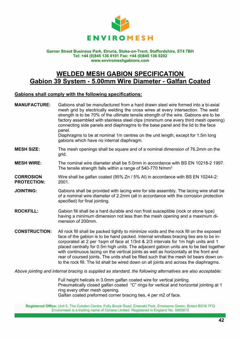
WELDED MESH GABION SPECIFICATION Gabion 39 System - 5.00mm Wire Diameter - Galfan Coated
Gabions shall comply with the following specifications:
MANUFACTURE: Gabions shall be manufactured from a hard drawn steel wire formed into a bi-axial mesh grid by electrically welding the cross wires at every intersection. The weld strength is to be 70% of the ultimate tensile strength of the wire. Gabions are to be factory assembled with stainless steel clips (minimum one every third mesh opening) connecting side panels and diaphragms to the base panel and the lid to the face panel.Diaphragms to be at nominal 1m centres on the unit length, except for 1.5m long gabions which have no internal diaphragm.
MESH SIZE: The mesh openings shall be square and of a nominal dimension of 76.2mm on the grid.
MESH WIRE: The nominal wire diameter shall be 5.0mm in accordance with BS EN 10218-2 1997. The tensile strength falls within a range of 540-770 N/mm2.
CORROSION Wire shall be galfan coated (95% Zn / 5% Al) in accordance with BS EN 10244-2:PROTECTION: 2001.
JOINTING: Gabions shall be provided with lacing wire for site assembly. The lacing wire shall be of a nominal wire diameter of 2.2mm (all in accordance with the corrosion protection specified) for final jointing.
ROCKFILL: Gabion fill shall be a hard durable and non frost susceptible (rock or stone type) having a minimum dimension not less than the mesh opening and a maximum di-mension of 200mm.
CONSTRUCTION: All rock fill shall be packed tightly to minimize voids and the rock fill on the exposed face of the gabion is to be hand packed. Internal windlass bracing ties are to be in-corporated at 2 per 1sqm of face at 1/3rd & 2/3 intervals for 1m high units and 1 placed centrally for 0.5m high units. The adjacent gabion units are to be tied together with continuous lacing on the vertical joints as well as horizontally at the front and rear of coursed joints. The units shall be filled such that the mesh lid bears down on-to the rock fill. The lid shall be wired down on all joints and across the diaphragms.
Above jointing and internal bracing is supplied as standard, the following alternatives are also acceptable:
Full height helicals in 3.0mm galfan coated wire for vertical jointing.Pneumatically closed galfan coated “C” rings for vertical and horizontal jointing at 1 ring every other mesh opening. Galfan coated preformed corner bracing ties, 4 per m2 of face.
42
Registered Office: Unit 5, The Cobden Centre, Folly Brook Road, Emerald Park, Emersons Green, Bristol BS16 7FQEnviromesh is a trading name of Cerana Limited. Registered in England No. 5065615
Garner Street Business Park, Etruria, Stoke-on-Trent, Staffordshire, ST4 7BHTel: +44 (0)845 136 0101 Fax: +44 (0)845 136 0202
www.enviromeshgabions.com
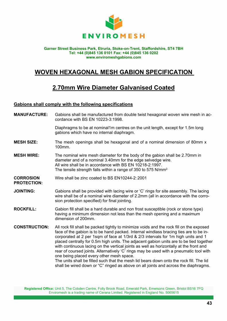
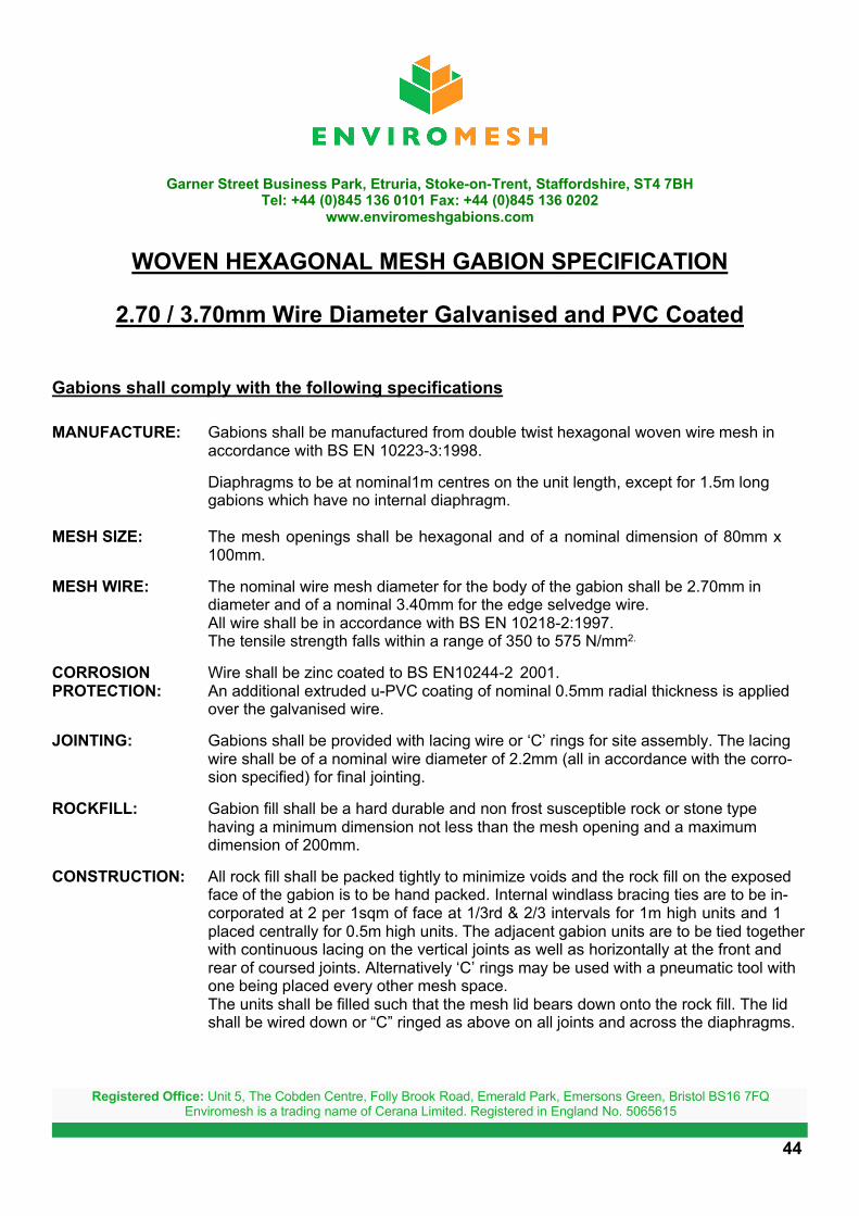
WOVEN HEXAGONAL MESH GABION SPECIFICATION
2.70mm Wire Diameter Galvanised Coated
Gabions shall comply with the following specifications
MANUFACTURE: Gabions shall be manufactured from double twist hexagonal woven wire mesh in ac-cordance with BS EN 10223-3:1998.
Diaphragms to be at nominal1m centres on the unit length, except for 1.5m longgabions which have no internal diaphragm.
MESH SIZE: The mesh openings shall be hexagonal and of a nominal dimension of 80mm x 100mm.
MESH WIRE: The nominal wire mesh diameter for the body of the gabion shall be 2.70mm in diameter and of a nominal 3.40mm for the edge selvedge wire.All wire shall be in accordance with BS EN 10218-2:1997.The tensile strength falls within a range of 350 to 575 N/mm2.
CORROSION Wire shall be zinc coated to BS EN10244-2: 2001 PROTECTION:
JOINTING: Gabions shall be provided with lacing wire or ‘C’ rings for site assembly. The lacing wire shall be of a nominal wire diameter of 2.2mm (all in accordance with the corro-sion protection specified) for final jointing.
ROCKFILL: Gabion fill shall be a hard durable and non frost susceptible (rock or stone type) having a minimum dimension not less than the mesh opening and a maximum dimension of 200mm.
CONSTRUCTION: All rock fill shall be packed tightly to minimize voids and the rock fill on the exposed face of the gabion is to be hand packed. Internal windlass bracing ties are to be in-corporated at 2 per 1sqm of face at 1/3rd & 2/3 intervals for 1m high units and 1 placed centrally for 0.5m high units. The adjacent gabion units are to be tied together with continuous lacing on the vertical joints as well as horizontally at the front and rear of coursed joints. Alternatively ‘C’ rings may be used with a pneumatic tool with one being placed every other mesh space.The units shall be filled such that the mesh lid bears down onto the rock fill. The lid shall be wired down or “C” ringed as above on all joints and across the diaphragms.
43
Registered Office: Unit 5, The Cobden Centre, Folly Brook Road, Emerald Park, Emersons Green, Bristol BS16 7FQEnviromesh is a trading name of Cerana Limited. Registered in England No. 5065615
Garner Street Business Park, Etruria, Stoke-on-Trent, Staffordshire, ST4 7BHTel: +44 (0)845 136 0101 Fax: +44 (0)845 136 0202
www.enviromeshgabions.com
WOVEN HEXAGONAL MESH GABION SPECIFICATION
2.70 / 3.70mm Wire Diameter Galvanised and PVC Coated
Gabions shall comply with the following specifications
MANUFACTURE: Gabions shall be manufactured from double twist hexagonal woven wire mesh in accordance with BS EN 10223-3:1998.
Diaphragms to be at nominal1m centres on the unit length, except for 1.5m long gabions which have no internal diaphragm.
MESH SIZE: The mesh openings shall be hexagonal and of a nominal dimension of 80mm x 100mm.
MESH WIRE: The nominal wire mesh diameter for the body of the gabion shall be 2.70mm in diameter and of a nominal 3.40mm for the edge selvedge wire.All wire shall be in accordance with BS EN 10218-2:1997.The tensile strength falls within a range of 350 to 575 N/mm2.
CORROSION Wire shall be zinc coated to BS EN10244-2 2001.PROTECTION: An additional extruded u-PVC coating of nominal 0.5mm radial thickness is applied
over the galvanised wire.
JOINTING: Gabions shall be provided with lacing wire or ‘C’ rings for site assembly. The lacing wire shall be of a nominal wire diameter of 2.2mm (all in accordance with the corro-sion specified) for final jointing.
ROCKFILL: Gabion fill shall be a hard durable and non frost susceptible rock or stone typehaving a minimum dimension not less than the mesh opening and a maximumdimension of 200mm.
CONSTRUCTION: All rock fill shall be packed tightly to minimize voids and the rock fill on the exposed face of the gabion is to be hand packed. Internal windlass bracing ties are to be in-corporated at 2 per 1sqm of face at 1/3rd & 2/3 intervals for 1m high units and 1 placed centrally for 0.5m high units. The adjacent gabion units are to be tied together with continuous lacing on the vertical joints as well as horizontally at the front and rear of coursed joints. Alternatively ‘C’ rings may be used with a pneumatic tool with one being placed every other mesh space.The units shall be filled such that the mesh lid bears down onto the rock fill. The lid shall be wired down or “C” ringed as above on all joints and across the diaphragms.
44
Registered Office: Unit 5, The Cobden Centre, Folly Brook Road, Emerald Park, Emersons Green, Bristol BS16 7FQEnviromesh is a trading name of Cerana Limited. Registered in England No. 5065615
Tips on Gabion Wall DesignWhen designing walls the following tips may be of help:
1 Gabion courses should fully bear down on the unit below and not overhang at the rear.
2 Slopes of retained fill cannot exceed the internal angle of friction of the soil.
3 In poor ground bearing conditions opt for a larger base and / or stepped wallconfiguration to even bearing pressures. Embed a wider founding gabion to spread the loading over a greater area.
4 Avoid where possible walls built with a vertical face. The section will increase and deformation on the face will be more visible.
5 For quality installations, use the Gabion 27 system which has a heavier mesh face and smaller cell size.
For standard system 39 gabions, opt for a heavier facing mesh
6 When using standard gabion 39 system, nominally step the face of the wall at each course.
7 Gabion 27 system has factory preset offsets for each course or can be flush.
8 Ensure that the design is based on factual soil investigations.
9 Select the gabion system based on stability, economy of design, volume of earth works required and quality of installation required.
Gabion 27 system will give the best overall performance.
10 Seek design support from the manufacturer / supplier of gabions.
Enviromesh provide a free desktop design feasibility service.
45
CONTACTS:
Roger Farmer Mob: +44 (0) 7725 244 636Technical Director Email: [email protected]
Neil Holmes Mob: +44 (0) 7725 244 637Commercial Director Email: [email protected]
01/02/07 Edition 1
Garner Street Business Park, Etruria, Stoke-on-Trent,Staffordshire, ST4 7BH
Tel: +44 (0) 845 136 0101 Fax: +44 (0) 845 136 0202
www.enviromeshgabions.com
Registered Office: Unit 5, The Cobden Centre, Folly Brook Road, Emerald Park, Emersons Green, Bristol BS16 7FQEnviromesh is a trading name of Cerana Limited. Registered in England No. 5065615