designing type-c + pd systems - universal serial · pdf file · 2017-11-15designing...
TRANSCRIPT

USB Developer Days – October 24-25, 2017 USB Implementers Forum © 2017
Designing Type-C + PD Systems
Gregory Watkins – Texas Instruments
USB Developer Days 2017
Taipei, Taiwan
October 24-25, 2017
1

USB Developer Days – October 24-25, 2017 USB Implementers Forum © 2017
Agenda
• System Components
• Data Switching
• Power Switching
• System Examples
2
USB Developer Days – October 24-25, 2017 USB Implementers Forum © 2017
Agenda
• System Components
• Data Switching
• Power Switching
• System Examples
3

USB Developer Days – October 24-25, 2017 USB Implementers Forum © 2017
System Components
• Type-C + PD System Primary Components
• System Components Visualized
4
USB Developer Days – October 24-25, 2017 USB Implementers Forum © 2017
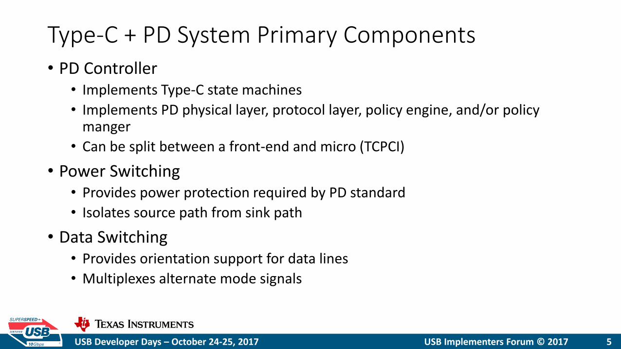
Type-C + PD System Primary Components • PD Controller
• Implements Type-C state machines
• Implements PD physical layer, protocol layer, policy engine, and/or policy manger
• Can be split between a front-end and micro (TCPCI)
• Power Switching • Provides power protection required by PD standard
• Isolates source path from sink path
• Data Switching • Provides orientation support for data lines
• Multiplexes alternate mode signals
5

USB Developer Days – October 24-25, 2017 USB Implementers Forum © 2017
System Components Visualized
6
Variable
DC2DC
USB 3.1
Mux
USB 3.1
Sig Con
CC/HS
ESD
Short to
VBUS
Protection
SS ESD
Alt. Mode
Sig Con
Alt. Mode
Mux
Reverse
Current
Protection
IEC/UL
Over
Current
VBUS
Discharge
Over
Voltage
Power
Mux
Dead
Battery
LDO
VBUS
FET
VBUS
FET Drive
Thermal
Shutdown
VCONN CC
Detect/Flip
PD PHY
Modem
PD
Manager
MCU
USB 2.0
Mux
USB 2.0
Endpoint
VB
US
CC
S
BU
R
X2/T
X2
D+
/D-
VC
ON
N
RX
1/T
X1
USB Developer Days – October 24-25, 2017 USB Implementers Forum © 2017
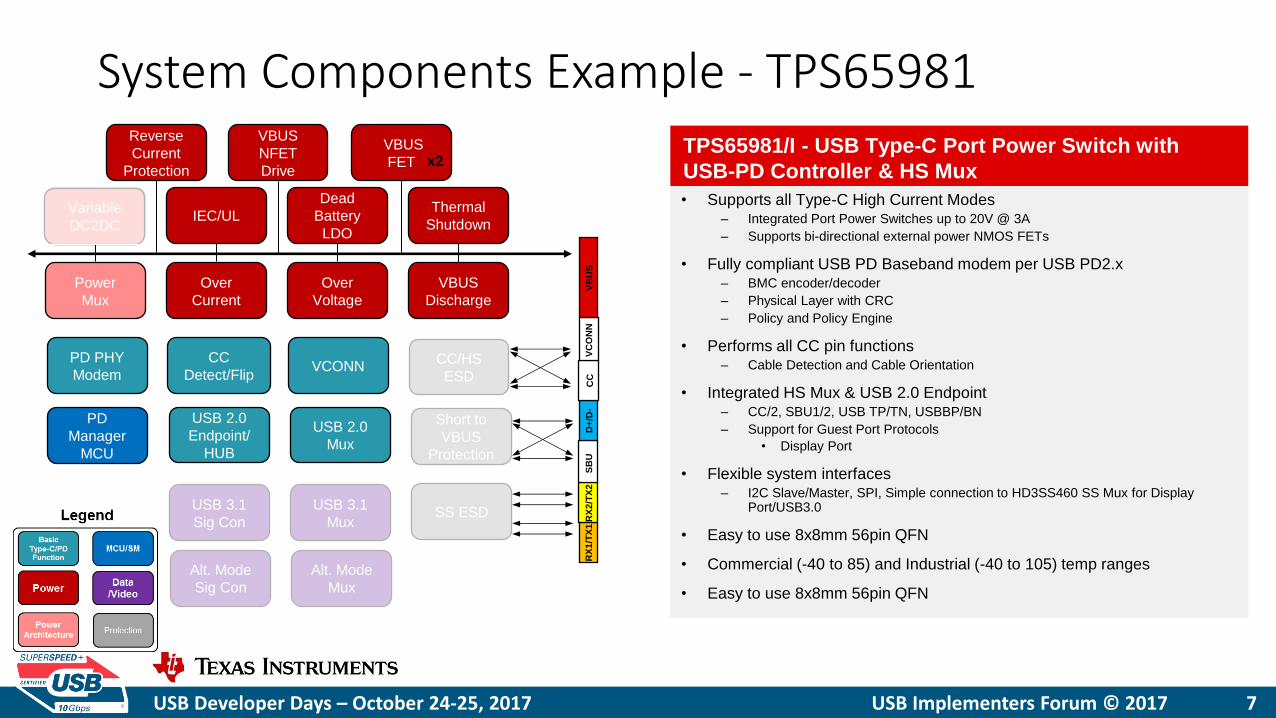
System Components Example - TPS65981
7
Variable
DC2DC
USB 3.1
Mux
USB 3.1
Sig Con
CC/HS
ESD
Short to
VBUS
Protection
SS ESD
Alt. Mode
Sig Con
Alt. Mode
Mux
Reverse
Current
Protection
IEC/UL
Over
Current
VBUS
Discharge
Over
Voltage
Power
Mux
Dead
Battery
LDO
VBUS
FET
VBUS
NFET
Drive
Thermal
Shutdown
VCONN CC
Detect/Flip
PD PHY
Modem
PD
Manager
MCU
USB 2.0
Mux
USB 2.0
Endpoint/
HUB
TPS65981/I - USB Type-C Port Power Switch with
USB-PD Controller & HS Mux
• Supports all Type-C High Current Modes – Integrated Port Power Switches up to 20V @ 3A
– Supports bi-directional external power NMOS FETs
• Fully compliant USB PD Baseband modem per USB PD2.x – BMC encoder/decoder
– Physical Layer with CRC
– Policy and Policy Engine
• Performs all CC pin functions – Cable Detection and Cable Orientation
• Integrated HS Mux & USB 2.0 Endpoint – CC/2, SBU1/2, USB TP/TN, USBBP/BN
– Support for Guest Port Protocols
• Display Port
• Flexible system interfaces – I2C Slave/Master, SPI, Simple connection to HD3SS460 SS Mux for Display
Port/USB3.0
• Easy to use 8x8mm 56pin QFN
• Commercial (-40 to 85) and Industrial (-40 to 105) temp ranges
• Easy to use 8x8mm 56pin QFN
x2
Variable
DC2DC
VB
US
CC
S
BU
R
X2/T
X2
D+
/D-
VC
ON
N
RX
1/T
X1
USB Developer Days – October 24-25, 2017 USB Implementers Forum © 2017 8
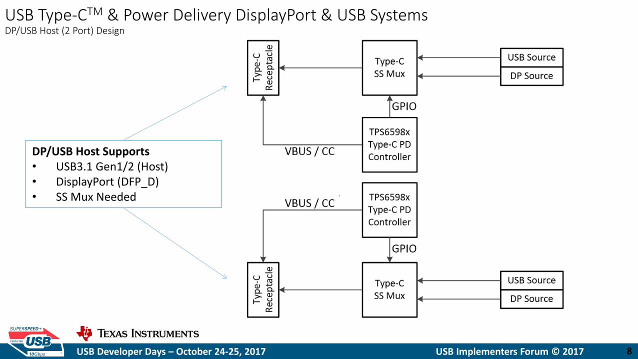
USB Type-CTM & Power Delivery DisplayPort & USB Systems DP/USB Host (2 Port) Design
DP/USB Host Supports • USB3.1 Gen1/2 (Host) • DisplayPort (DFP_D) • SS Mux Needed
USB Developer Days – October 24-25, 2017 USB Implementers Forum © 2017
Agenda
• System Components
• Data Switching
• Power Switching
• System Examples
9
USB Developer Days – October 24-25, 2017 USB Implementers Forum © 2017
Data Switching • Super Speed Mux
• Data Mux
• Alternate Mode Mux
10
USB Developer Days – October 24-25, 2017 USB Implementers Forum © 2017
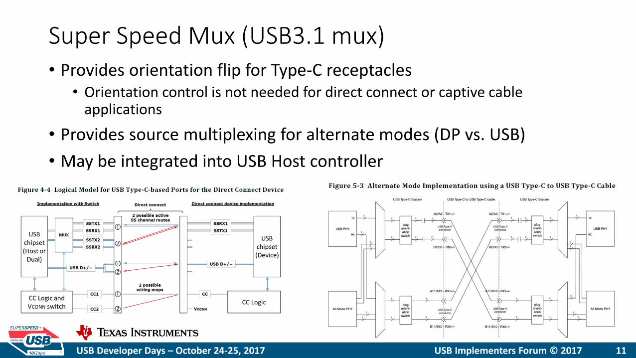
Super Speed Mux (USB3.1 mux) • Provides orientation flip for Type-C receptacles
• Orientation control is not needed for direct connect or captive cable applications
• Provides source multiplexing for alternate modes (DP vs. USB)
• May be integrated into USB Host controller
11

USB Developer Days – October 24-25, 2017 USB Implementers Forum © 2017
Data Mux (USB2 Mux) • Only needed for very specialized applications that split top and
bottom D+/D- for alternate mode use
• Orientation control is handled without a mux by shorting top and bottom D+/D- together in the receptacle
12

USB Developer Days – October 24-25, 2017 USB Implementers Forum © 2017
Alternate Mode Mux (SBU Mux) • Provides SBU isolation when not operating inside an alternate mode
• Once an alternate mode is entered connects the appropriate alternate mode signals to the SBU pins based on orientation
• Typically integrated alongside the SS Mux
13
USB Developer Days – October 24-25, 2017 USB Implementers Forum © 2017
Agenda
• System Components
• Data Switching
• Power Switching
• System Examples
14
USB Developer Days – October 24-25, 2017 USB Implementers Forum © 2017
Power Switching
• Power Switching Considerations
• Power Switch Architectures
• Screwdriver Test
• Reverse Current Protection
15

USB Developer Days – October 24-25, 2017 USB Implementers Forum © 2017
Power Switching Considerations • Cost
• Board Area
• Protection Features • Over Current
• Over Temperature
• Over Voltage
• Reverse Current Protection
• Fault Reporting • PD3 introduced the Alert message which requires knowledge of why a Hard
Reset occurred
16

USB Developer Days – October 24-25, 2017 USB Implementers Forum © 2017
Power Switch Architectures
Discrete Paths External Load Switches Integrated Load Switches
20 V Load Switch
20 V Load Switch
Charger
5 V Supply
VBUS
Charger
5 V Supply
VBUS 20 V Load
Switch
20 V Load Switch
Charger
5 V Supply
VBUS
PD Controller
PD Controller
PD Controller
USB Developer Days – October 24-25, 2017 USB Implementers Forum © 2017
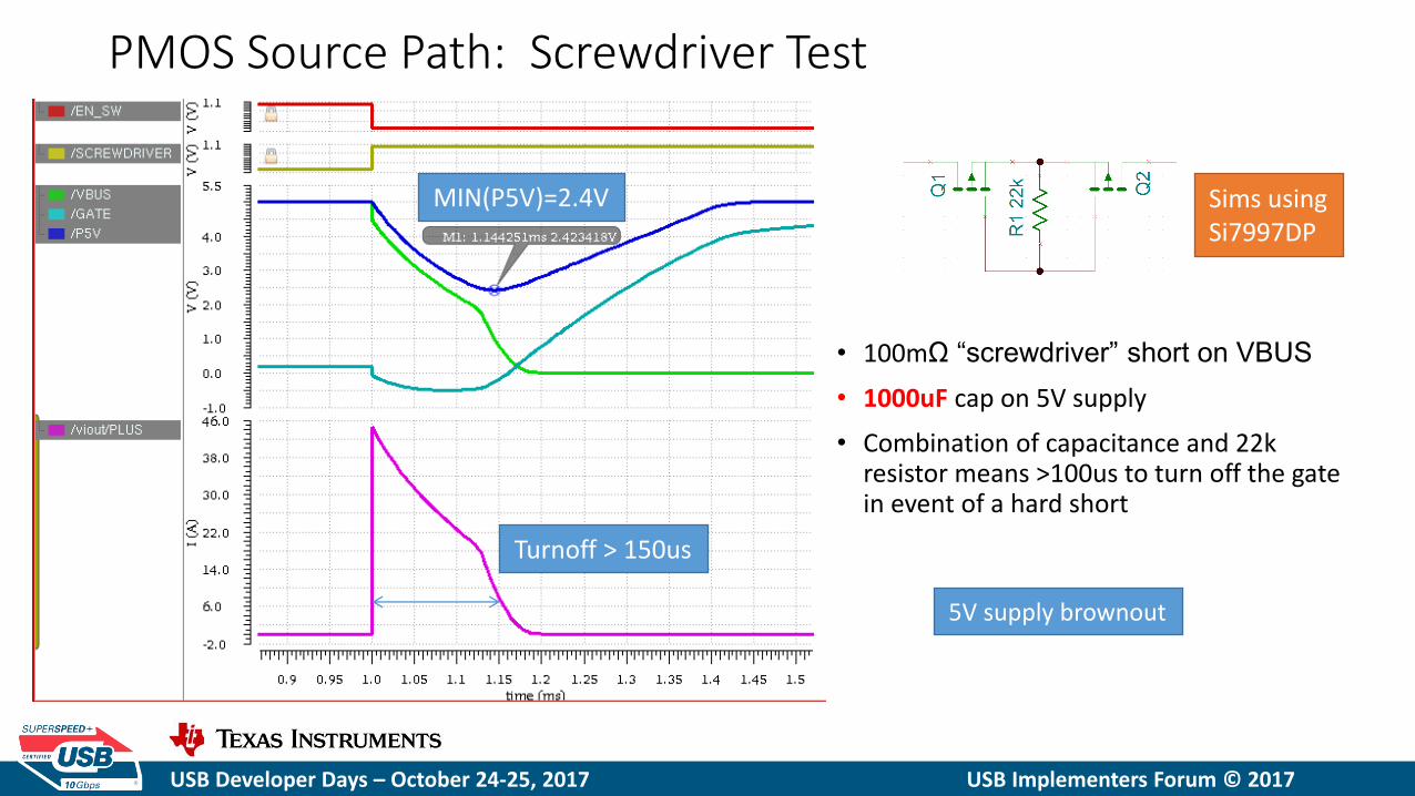
PMOS Source Path: Screwdriver Test
• 100mΩ “screwdriver” short on VBUS
• 1000uF cap on 5V supply
• Combination of capacitance and 22k resistor means >100us to turn off the gate in event of a hard short
Sims using Si7997DP
MIN(P5V)=2.4V
5V supply brownout
Turnoff > 150us

USB Developer Days – October 24-25, 2017 USB Implementers Forum © 2017
Integrated Power Paths: Screwdriver Test
No Brownout
5x lower cap
DC / DC
PD Controller
VBUS PPHV = 5 V
SYSPWR
ON
OFF
200 uF
USB Developer Days – October 24-25, 2017 USB Implementers Forum © 2017
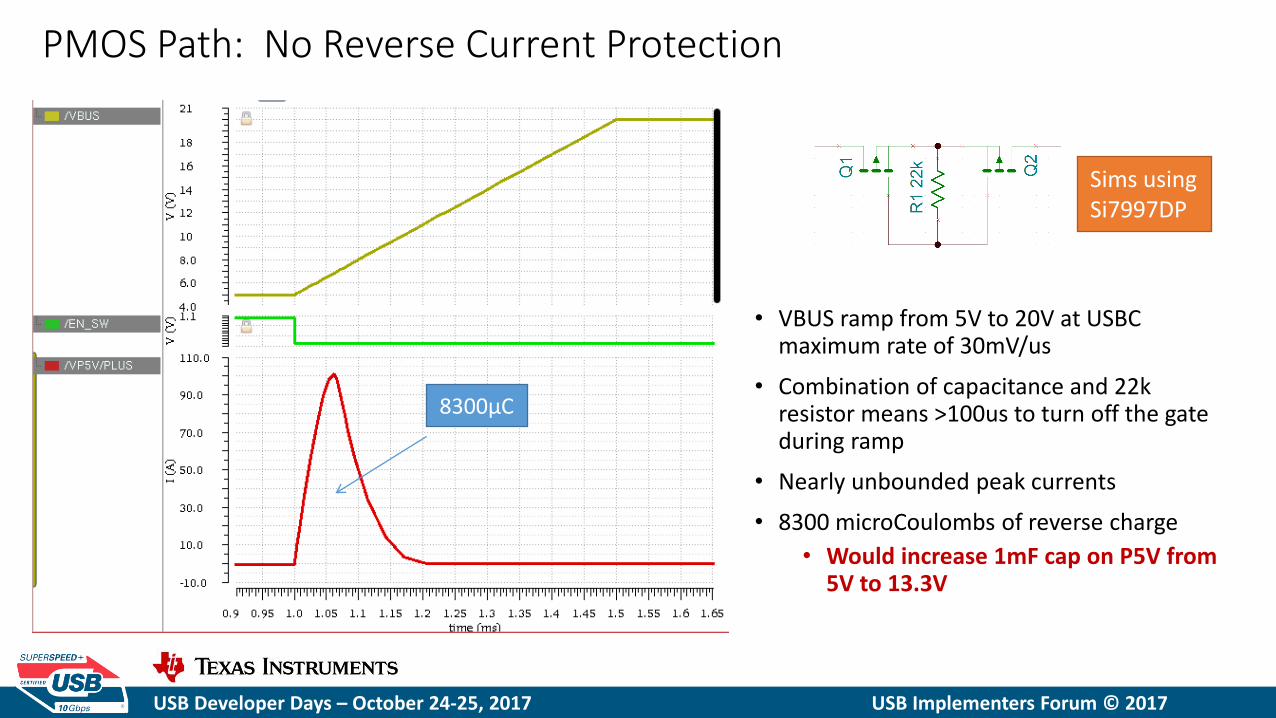
PMOS Path: No Reverse Current Protection
• VBUS ramp from 5V to 20V at USBC maximum rate of 30mV/us
• Combination of capacitance and 22k resistor means >100us to turn off the gate during ramp
• Nearly unbounded peak currents
• 8300 microCoulombs of reverse charge
• Would increase 1mF cap on P5V from 5V to 13.3V
Sims using Si7997DP
8300μC

USB Developer Days – October 24-25, 2017 USB Implementers Forum © 2017
Integrated Power Paths: RCP
No back-feeding of voltage Seamless transition between power sources
DCDC
VBUS
SYSPWR
OFF
PD Controller
ON w / RCP
OFF
VBUS
PPHV
120 uF
DCDC PPHV
120 uF
SYSPWR
ON w / RCP
EVM # 1
EVM # 2
20 V PD
Adapter
5 V PD
Adapter
PD Controller
USB Developer Days – October 24-25, 2017 USB Implementers Forum © 2017
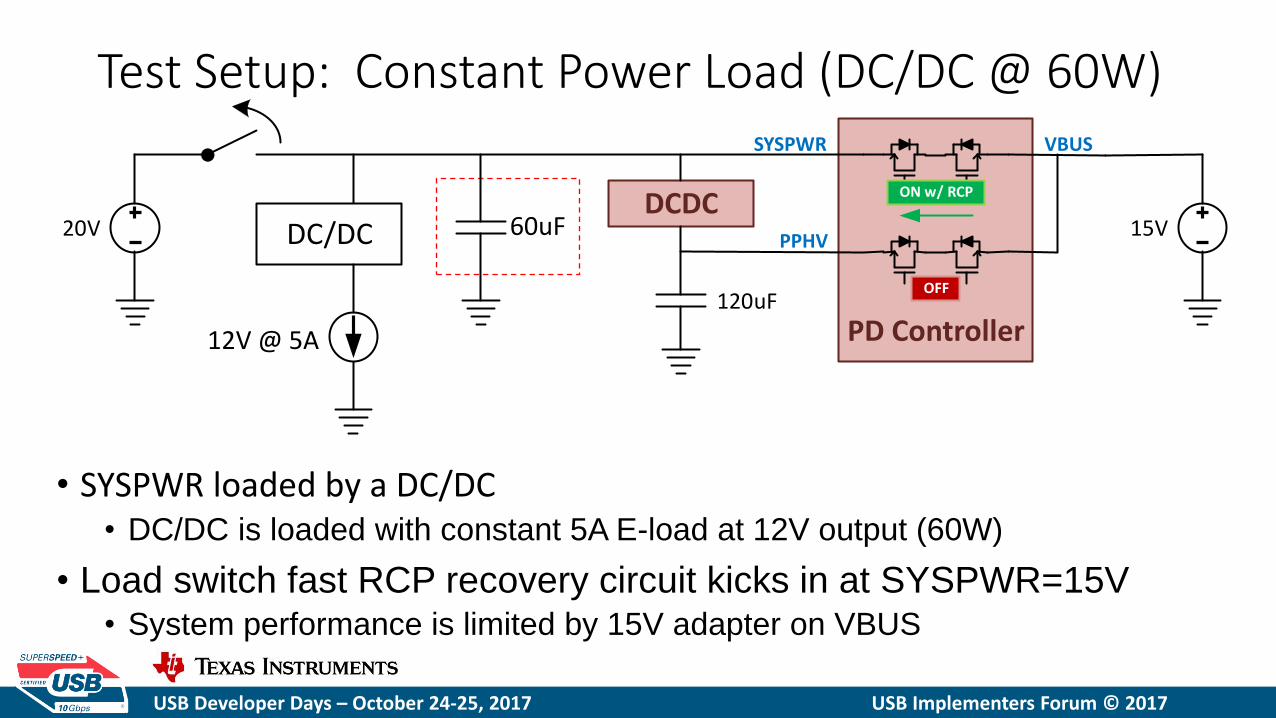
Test Setup: Constant Power Load (DC/DC @ 60W)
• SYSPWR loaded by a DC/DC • DC/DC is loaded with constant 5A E-load at 12V output (60W)
• Load switch fast RCP recovery circuit kicks in at SYSPWR=15V • System performance is limited by 15V adapter on VBUS
60uF
12V @ 5A
15 V 20 V DCDC
SYSPWR
PD Controller
ON w / RCP
OFF
VBUS
PPHV
120 uF
DC / DC
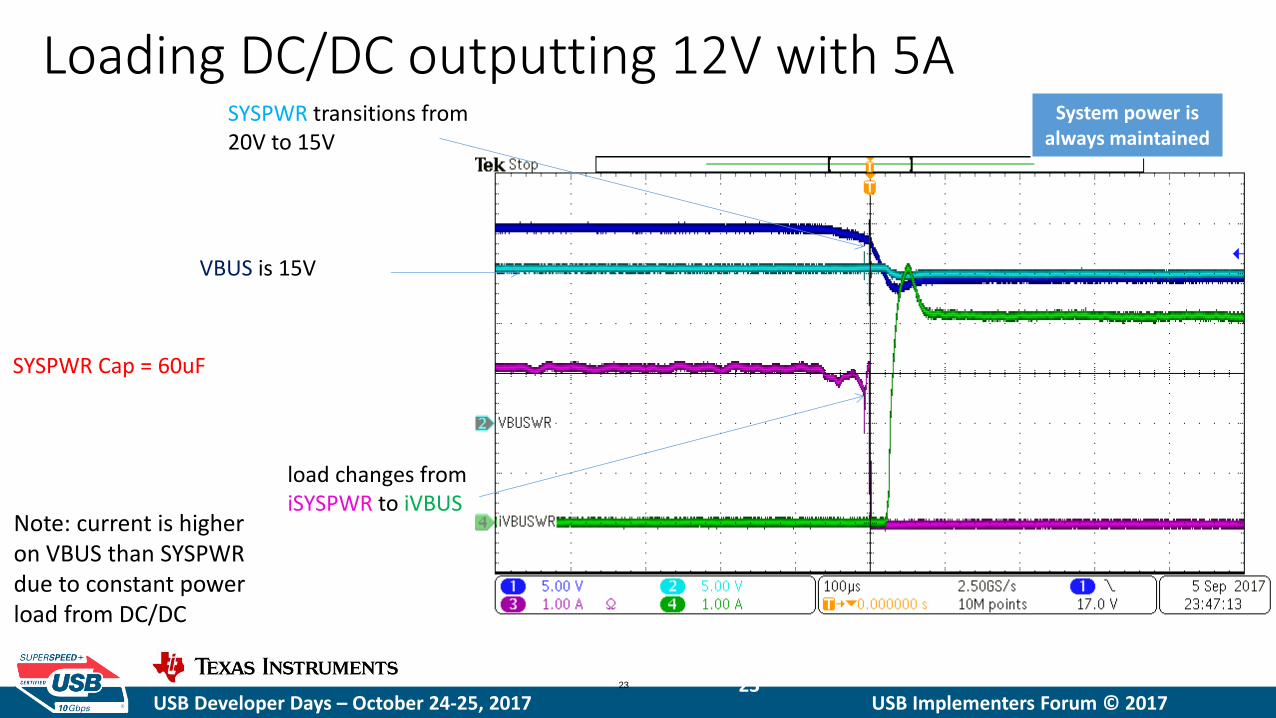
USB Developer Days – October 24-25, 2017 USB Implementers Forum © 2017 23 23
VBUS is 15V
SYSPWR transitions from 20V to 15V
load changes from iSYSPWR to iVBUS
System power is always maintained
Note: current is higher on VBUS than SYSPWR due to constant power load from DC/DC
Loading DC/DC outputting 12V with 5A
SYSPWR Cap = 60uF
USB Developer Days – October 24-25, 2017 USB Implementers Forum © 2017
Agenda
• System Components
• Data Switching
• Power Switching
• System Examples
24

USB Developer Days – October 24-25, 2017 USB Implementers Forum © 2017
System Examples
• USB Type-C & Power Delivery 3.0 Dual Port Host System
• USB Type-C & Power Delivery 3.0 Multiport Dongle
25

USB Developer Days – October 24-25, 2017 USB Implementers Forum © 2017
• USB Type-C & PD Full Featured Plug • DisplayPort & USB3 Device • Bi-directional Power (up to 20V / 3A)
• USB Type-C & PD Receptacle • USB3.0 Host • PD Sink up to 20V @ 3A
• USB PD3.0 Fast Role Swap Capable • Dynamic Power Advertisement w/ Bi-Directional Power • Video (up to 4K) via HDMI 2.0
PD Controllers’ dynamic and bi-directional power simplifies the system design when implementing USB PD3.0 PD Power Rules and Fast Role Swap
Power architecture ensures that the system supplies suppling data path will stay active during a Fast Role Swap
Features Benefits
USB Type-CTM & Power Delivery 3.0 Multiport Dongle TIDA-03027
System Level View
PD Controller
TI PWR HUB
DP to HDMI
USB Output
PD Controller
USB –C Output
HDMI Output
MUX
• Device Datasheets: ‒ TPS65983
‒ TUSB8041
‒ HD3SS3312
‒ TPD8S300
‒ LM3489
‒ TPS2500
‒ TPS54334
‒ TPS62065
‒ TPD13S523
‒ TPD1E01B04

USB Developer Days – October 24-25, 2017 USB Implementers Forum © 2017
USB Type-CTM & Power Delivery 3.0 Multiport Dongle Basic operation and use case

USB Developer Days – October 24-25, 2017 USB Implementers Forum © 2017
USB Type-CTM & Power Delivery 3.0 Multiport Adapter Bus-powered and self-powered operation
To meet PDP (Power Delivery Power) rules 5V/9V/15V/20V should be supported when providing power

USB Developer Days – October 24-25, 2017 USB Implementers Forum © 2017
USB Type-CTM & Power Delivery 3.0 Multiport Adapter Data and power path diagram

USB Developer Days – October 24-25, 2017 USB Implementers Forum © 2017
USB Type-CTM & Power Delivery 3.0 Multiport Adapter Bus-powered and self-powered

USB Developer Days – October 24-25, 2017 USB Implementers Forum © 2017
• System supplies must stay operational during (FRS) Fast Role Swap
• 5V USB Type-A VBUS
• 1.2V/3.3V USB Hub & DP to HDMI Supplies
• System supplies must handle low voltage and high voltage input
• Low voltage (bus-powered) down to 4V
• High voltage (self-powered) up to 21V
• System rail must have enough capacitance to support up to 3A during FRS
• 20V to 5V decay should be at least 5ms for CC signaling FRS messaging
• At ~3A around 600uF of bulk cap is needed
• PD power path must be bi-directional
• The dongle will be the “old source new sink” for a FRS
• The power path must be enabled to allow the “old sink new source” to power the dongle
USB Type-CTM & Power Delivery 3.0 Multiport Adapter Fast Role Swap Design Considerations
USB Developer Days – October 24-25, 2017 USB Implementers Forum © 2017
Q&A
35