designing the low pressure oil return system
TRANSCRIPT

Sporlan’s Oil Level Control System components were developed to offer the refrigeration industry an oil level control system of the highest quality. The heart of the system is the Oil Level Control which, when matched with the Oil Reservoir, Check Valve, OF Oil Filter and perhaps the Y1236-C Pressure Differential Valve, maintains a minimum oil level in the compressor crankcase during all phases of system operation.
The System Features These Advantages:
Externally adjustable Oil Level Controls
Oil Level Control – Suitable for up to 90 psi differential pressure, optional oil level equalization connection
High performance oil filters
Choice of settings on Pressure Differential Check Valve
Externally adjustable Y1236-C allows for desired differential above suction pressure
Oil Reservoirs, Oil Level Controls and OF Oil Filters – UL listed
Numerous adaptors available for various types of compressors
Designing the Low Pressure Oil Return System
Oil must be present to lubricate the compressor. However, oil becomes a detriment to system perfor‑mance if present in large quantities in the evaporator. Therefore, it’s necessary to control the distribution of oil within the system.
In multi‑compressor parallel systems, oil levels must be maintained in each compressor regardless of the individual compressor’s oil consumption rate. Oil pumped by compressors may vary considerably, depending on the compressor model, age and operating conditions.
When oil is pumped by the compressor, it flows through the common discharge header to an oil separa‑tor. The oil separator’s function is to separate the oil from the discharge gases. Because the oil separator does not have a large holding capacity, the oil is transferred to an oil reservoir.
As it passes from the oil separator to the oil reservoir, the oil is at a high discharge pressure. This pressure must be reduced to a pressure slightly higher than the compressor crankcase. The pressure in the oil reser‑voir is reduced by boiling the refrigerant in the oil, and relieving the pressure above the oil through a vent line to the suction header. The pressure in the oil reservoir is maintained, slightly above the suction header pressure, by means of an Oil Differential Check Valve installed in the vent line. At its reduced pressure the oil is then fed to the Oil Level Control which meters the oil to the compressor equal to its pumping rate, and thereby maintains the oil level specified by the compressor manufacturer. The Oil Level Control functions by adding oil when the level is low – it cannot correct an oil level that is too high.
To obtain proper oil return, each of the oil system components must be selected according to the require‑ments of the overall oil control system.
IL LEVEL control system
January 2008 / Bulletin 110-10

Page 2 / Bulletin 110-10
High pressure oil return systems are fabricated slightly different than low pressure oil systems, but they achieve the same result of supply‑ing oil to the compressor. Both types of systems are used within the industry.
The oil separator used on the high pressure systems is designed to also serve as an oil reservoir. The oil in the reservoir is at a dis‑
charge pressure. This pressure must be reduced to a pressure slightly higher than the compressor crankcase so that it can be managed by the oil level control. This can be accomplished by using the Y1236‑C Pressure Differential Valve.
IndependentSuction
Oil Separator / Reservoir
OF-303, OF-303-BP
or ROF-413-T Oil Filter
Y1236-C
Common Discharge Header
To Condenser
Oil Level Controls
Common Suction Header
IndependentSuction
OF-303, or ROF-413-T
Oil Filter
Oil Differential Check Valve
POR Oil ReservoirLocation of
OF-303-BP
Common Discharge Header
Common Suction Header
To Condenser
Oil Level Controls
Designing the High Pressure Oil Return System
Figure 2
Figure 1
A
B
DE
C
D D
FOR USE ON REFRIGERATION and/or AIR CONDITIONING SYSTEMS ONLYBulletin 110-10, January 2008 supersedes Bulletin 110-10, January 2004, Bulletin 110-10-1 January 2002 and Bulletin 110-30, August 1997, and all prior publications.
© Copyright 2008 By parker hannifin Corporation, Washington, Missouri

Bulletin110-10 / Page 3
Oil Reservoir – Type POR
The Sporlan Oil Reservoirs (POR‑2, 3 and 4) contain the oil that is not within the crankcase, the oil separator, or in circulation. The res‑ervoirs have an inlet and an outlet service valve so it can be isolated from the rest of the system. Or the oil supply from the oil reservoir to the Oil Level Control can be interrupted for servicing.
When adding an Oil Reservoir to an existing system or replacing an oil reservoir on an existing system, it should only be filled to the top of the lower sightglass. As the system is placed into operation, the oil level should be observed. If the oil level rises above the upper sightglass, some oil should be drained from the reservoir.
The level of oil should never be allowed to drop below the bottom of the lower sightglass.
On new system start‑ups the reservoir should be filled to the top of the upper sightglass. As the system runs, oil should be added to maintain a level between the two sightglasses for the POR‑2. For the POR‑3 and 4, the level should be somewhere between the top and middle sightglasses. This procedure may require several charges as the oil is absorbed in the refrigerant and coats the low side tubing.
Y1236-C Pressure Differential Valve
The Sporlan Y1236‑C Pressure Differential Valve is designed for use on high pressure oil return systems or others applications where a differential pressure regulator is required. The valve permits the Oil Level Control mounted at the compressor to feed at any spec if ied level because the pressurized oil at the control is slightly greater than crankcase pressure. Without the Y1236‑C, excessive pres sure drop across the mechanical oil level control would cause the control to overfeed the compressor. This occurs because more force is required on the float ball, thereby a higher oil level, to overcome the pressure drop through the port to close the oil level control.
The Y1236‑C reduces the inlet pressure by controlling a differen t ial across the valve outlet and the force supplied to the valve’s element. With high pressure oil return systems, suction pressure is supplied to the element when located between the oil separator/reservoir and the oil level control. The valve is adjustable from a 10 to 25 psi dif‑ferential. Turning the adjustment stem counterclockwise reduces the differential. One turn of adjustment is equal to 2.5 psi change. The standard differential setting from the factory is 17 psi.
The Y1236‑C includes a removable 100 mesh inlet strainer to pro tect the valve from circulating contaminants. The removable strainer can be purchased separately (p/n: 1538‑000).
1.93"
2.02"
1.62"1.35"
0.97"
2.43"
6.10"3/8" SAE
Flare(Outlet)
3/8" SAEFlare(Inlet)
1/4" SAEFlare
Specifications:
System ComponentsFigure 3
Features and Benefits
Sight glass ports with float ball indicators for oil level monitoring
3/8” male flare rotalock valves shipped with oil reservoir allow for easy adjustment when piping into system
3/8” male flare vent port – for con-nection to the suction line
Mounting studs and brackets
500 psi maximum working pres-sure
Powder coating passes 500 hour ASTM salt spray
MODEL NUMBER TOTAL CApACITY IN GALLONS
‘A’ CApACITY IN GALLONS
‘B’ CApACITY IN GALLONS
NUMBER OF SIGhT GLASSES LENGTh IN INChES ShELL DIAMETER
IN INChES
POR-2 2 3/4 3/4 2 18 6.0
POR-3 3 3/4 1-1/2 3 23 6.0
POR-4 4 3/4 2-3/4 3 36 6.0
‘A’ capacity is the capacity to the first sight glass.‘B’ capacity is the capacity between the two sight glasses for the POR-2 and the top and bottom sight glasses for the POR-3 and POR-4.
Underwriters Laboratories Inc. Listed, Guide No. SROT, File No. SA6386 (N)

Page 4 / Bulletin 110-10
Oil Differential Check Valve – Types OCV-5, OCV-10, OCV-20
The Sporlan Oil Differential Check Valve (OCV) is installed on the 3/8” SAE fitting on the top of the Oil Reservoir. It allows pressure to be relieved from the reservoir to the suction as required to maintain a pressure in the reservoir at a preset level above the suction pressure. The pressure differential created by the OCV assures oil flow from the reservoir to the Oil Level Control, providing there is adequate oil in the reservoir.
The OCV will only relieve pressure from the reservoir in excess of its fixed set point. Systems with fluctuating suction pressure, as a result of compressor unloaders, staging or other suction line controls, must be fitted with an OCV with a differential greater than the suction pressure fluctuation. This assures oil flow from the reservoir through the oil level control to the compressor crankcase.
Sporlan offers OCV’s with a 5, 10 and 20 psi fixed differential setting. However, Sporlan recommends the use of an OCV‑20 on all field built‑up applications. Equipment manufacturers may, after extensive tests, employ an OCV with a different pressure setting. Example: OCV‑5
OCV-20 All check valves have 3/8”
SAE connections
All brass construction
Oil Level Controls
The purpose of the Sporlan Oil Level Control is to regulate the flow of oil to the compres sor crankcase and maintain a minimum oil level as specified by the compressor manufac turer for a given application. The Oil Level Control is adjustable between 1/2 sightglass and 1/4 sightglass at any pressure differential between 5 and 90 psi. As the level of oil drops in the compressor crankcase, the float of the Oil Level Control is lowered and opens a needle valve. This allows oil to flow from the oil reservoir to the compres‑sor crankcase, see Figure 5.
Several Oil Level Controls have a 3/8” SAE oil equalization fitting. The equalization fitting allows the Oil Level Controls to be interconnected, permitting oil transfer between a series of compressors. This transfer is sometimes necessary due to a sudden increase in oil level resulting from oil returning down the suction line. If an equalizer is not required, a cap must be installed.
CAUTION: If a sudden load increase, or system defrost, causes a large amount of oil to return through the suction line, the Oil Level Control will not prevent the oil level from rising above the control point.
The Sporlan Oil Level Control may be bolted either directly to the compressor crankcase or, depending on the compressor model, may be adapted to the crankcase by means of one of the adaptors available, see table on page 6. Care must be taken when installing an Oil Level Control to make sure the compressor is leveled, and the Oil Level Control compressor fitting and sightglass fitting are on the same elevation.
A slight amount of tolerance is provided in the bolt holes to allow for rotating the Oil Level Control to make sure that the sightglass is on the same level as the compressor connection. If the compressor and Oil Level Control are not level, a false reading may be given in the sightglass.
OL-60XHUnderwriters Laboratories Inc. Listed, Guide No. SFJQ, File No. SA5460 (N)
NOTES: Model OL-60XH-1 is identical to OL-60XH but less equalization fitting.
All Sporlan oil level controls now incorporate the OL-60 design for product simplification. The OL-60 Series are designed to handle a large operating range and replaces the OL-1 and 2 Series oil level controls.
Selection & Specifications
Inlet
MODEL NUMBER
ADJUSTMENT RANGE
FLANGE DESIGN FOR COMpRESSOR ATTAChMENT NUMBER OF ARMS LENGTh EQUALIZATION FITTING
OpTION/pLACEMENT
OL-60Ch
5-90 psiDifferential
3 bolt, 1-7/8” B.C. (47.6 mm B.C.) Two arms - standard length None
OL-60Fh 3 bolt, 1-7/8” B.C. (47.6 mm B.C.) Two arms - standard length Yes - bottom of drill hole at centerline of sightglass
OL-60hh-6 3 bolt, 1-7/8” B.C. (47.6 mm B.C.) One arm - standard length None
OL-60Nh-2 3 bolt, 1-7/8” B.C. (47.6 mm B.C.) Two arms - standard length Yes - fitting is .375 inch above standard location
OL-60Xh 3 bolt, 1-7/8” B.C. (47.6 mm B.C.) Two arms - short length Yes - bottom of drill hole at centerline of sightglass
OL-60Zh 4 bolt, 50 mm B.C. Two arms - short length Yes - bottom of drill hole at centerline of sightglass

Bulletin110-10 / Page 5
D
C
CE
BA
A
B
D
E
C
The following information must be considered before select‑ing an oil level control for a system. See Figure 1 on the low pressure oil return system for pressure locations.
Common suction header pressure – psig
Differential Check Valve setting (OCV) – psi
Oil Reservoir pressure (sum of and ) – psig
Crankcase pressure (compressor on common header) – psig
Crankcase pressure (compressor on independent suction - if applicable) – psig
The first step is to determine the pressure differential require‑ment of the oil level control. This can be determined on compressors with a common suction header by subtracting the pressure in the compressor crankcase from the Oil Reservoir pressure . For a compressor with an independent suction, the differential requirement is determined by subtract‑ing crank‑case pressure from pressure .
Determining Pressure Differential:
.777.777
Typical BoltHole Location
1-7/8” Bolt Center
3.68
3/8”SAE Flare.90
5.96
3.50
1.26
51.
500
3.68
REMOVE SEAL CAPTO ADJUST LEVEL
TURN STEMCW to LowerCCW to Raise(.05 per Turn)
3.56
3/8”SAE Flare
4.00
6.16
3.50
1.26
51.
500
3.56
REMOVE SEAL CAPTO ADJUST LEVEL
TURN STEMCW to LowerCCW to Raise(.05 per Turn)
EQUALIZATIONCONNECTION
OL-60FhOL-60Ch1; OL-60hh-6 and OL-60Nh-2
OL-60Ch OL-60Xh/OL-60ZhOL-60hh-6OL-60Fh OL-60Nh-2
3 Bolt Mounting Flange and Oil Sight Glass (S-OL)
Bolt holes are .271 diameter. The above hole con-figuration fits typical 3 bolt compressor sightglass and oil level control connections.
OL-60Zh Mounting FlangeBolt holes are .261 diameter. The above hole configura-tion fits typical 4 bolt compressor sightglass for select Bitzer compressors and other competing models.
1.34 3.16
3/8”SAE Flare.90
5.96
3.50
1.26
51.
500
REMOVE SEAL CAPTO ADJUST LEVEL
TURN STEMCW to LowerCCW to Raise(.05 per Turn)
3.83
1.34
3.16
3/8”SAE Flare.90
5.96
3.50
1.44
01.
620
REMOVE SEAL CAPTO ADJUST LEVEL
TURN STEMCW to LowerCCW to Raise(.05 per Turn)
3.83
OL-60Zh - (4 Bolt Flange)
1.34
OL-60Xh
Figure 5
1 OL-60CH and OL-60HH-6 are supplied less the equalization fitting.
.937.524
50 mm Bolt Center90°
.985
1.969
.261

Page 6 / Bulletin 110-10
NOTE: Use the OL-60ZH control only when specified. Shipping wt. is 4 lbs. for oil level controls and 1 lb. for adaptors.1 The OL-60ZH control is a possible option on select models. Use sightglass from compressor.2 Some compressor models have a smaller diameter port than the arm diameter of the oil level control. This situation can mislead the control in the amount of oil that is actually in the compressor. It is advisable the selection and adjustment of the control be reviewed in this situation.
Compressor Adaptor Requirements
The oil level control is factory set 3‑1/2 turns clockwise from the top stop. To set the oil level, remove the seal cap on top of the control. Turn the adjustment stem clockwise to lower and counter‑clockwise to raise. The proper adjustment can be determined from Figure 6. The oil level is given in eighths of an inch at various differential pressure conditions. Make adjustment (if necessary) prior to installing the control on the system.
Under no circumstance adjust beyond 10 turns down from the top stop or the control may be damaged. With care a person can feel the top and bottom stops. One of the symptoms of over‑adjustment of the oil level control is a totally full sightglass.
Data obtained using POE lubricant at 75°F with a one inch sightglass.
If a sudden load increase or system defrost causes a large amount of oil to return through the suction line the control will not prevent the oil level from rising above the control point.
Adjustment
7/8
3/4
5/8
1/2
3/8
1/4
1/8
OIL
LEV
EL, S
IGH
TGLA
SS
NUMBER OF TURNS1 2 3 4
OL-60
Top Position
8765 9
40 PSI70 PSI
60 PSI90 PSI
30 PSI80 PSI
5 PSI
FactorySetting
20 PSI10 PSI
DIFFERENTIAL PRESSURE
Figure 6
COMpRESSOR MANUFACTURER
COMpRESSOR MODEL NUMBER
COMpRESSOR ATTAChMENT
pATTERN
SpORLAN ADApTOR
KIT NUMBERSEALING METhOD SIGhTGLASS
Bitzer
2 KC, 2JC, 2HC, 2GC,2 FC, 2EC, 2DC, 2CC,4FC, 4EC, 4DC, 4CC
1-1/8” Thread AOL-MA/TE Use seal provided Use sightglass provided with adaptor
4VC, 4TC, 4PC, 4NC 3 Bolt, 1-7/8” B.C. (47.6 mm B.C.) None Use seal provided Use sightglass from compressor
4J, 4H, 4G, 6J, 6H, 6G, 6F 4 Bolt, 50 mm B.C.
None with the OL-60ZH control
Use seal provided with control Use sightglass from compressor
8GC, 8FC 3 Bolt, 1-7/8” B.C. (47.6 mm B.C.) AOL-R-1 Use seal provided Use sightglass from compressor
Bock
HA3-5, HG3-5, AM/F2-5 4 Bolt, 50 mm B.C. AOL-BO Q Use Teflon tape Use sightglass provided with adaptorHA8, HG6
F... 3 Bolt, 1-7/8” B.C. (47.6 mm B.C.) AOL-R-1 Use seal provided Use sightglass from compressor
Bristol — 15/16” – 20 Thread AOL-BR/TR Use seal provided Use sightglass provided with adaptor
Carrier06EA, 06ER 3 Bolt, 1-7/8” B.C. (47.6 mm B.C.) AOL-R-1
Use seal providedUse sightglass from compressor
06DA, 06DR, 5F, 5H 1-1/2” – 18 Thread AOL-C Use sightglass provided with adaptor
Copeland
Over 5 Ton 3 Bolt, 1-7/8” B.C. (47.6 mm B.C.) AOL-R-1 Use seal provided Use sightglass from compressor
Under 5 HP W 1-1/8” – 12 Thread AOL-A Use seal from compressor Use sightglass provided with adaptor
8R, 3D Front, 2D, 4D, 6D 3 Bolt, 1-7/8” B.C.(47.6 mm B.C.) AOL-R-1 Use seal provided Use sightglass from compressor
8D 3 Bolt, 1-7/8” B.C.(47.6 mm B.C.) Use control with standard length arms with AOL-R-1 adaptor. Use sightglass from compressor
Dorin 4 cyc-15 HP 3 Bolt, 1-7/8” B.C.(47.6 mm B.C.) Contact Sporlan
Dunham-Bush Big 4 3 Bolt, 1-7/8” B.C.(47.6 mm B.C.) AOL-R-1 Use seal provided Use sightglass from compressor
Frascold All models 3 Bolt, 1-7/8” B.C.(47.6 mm B.C.) AOL-R-1 Use seal provided Use sightglass from compressor
Maneurop MT..., LT... 1-1/8” – 18 Thread AOL-MA/TE Use seal provided Use sightglass provided with adaptor
prestcold E, C 42 mm Thread AOL-P Use Teflon tape Use sightglass provided with adaptor
TecumsehP, R, S, PA, RA, SA, CK, CM, CH, CG 1-1/8” – 12 Thread AOL-A Use seal from
compressor Use sightglass provided with adaptor— 1-1/8” – 18 Thread AOL-MA/TE Use seal provided
Trane
M, R 3 Bolt, 1-7/8” B.C.(47.6 mm B.C.) AOL-R-1 Use seal provided Use sightglass from compressor
K 3/4” NPT AOL-K-1 Use Teflon tapeUse sightglass provided with adaptor
— 15/16” – 20 Thread AOL-BR/TR Use seal provided
York GC, GS, JS 3 Bolt, 1-7/8” B.C.(47.6 mm B.C.) AOL-R-1 Use seal provided Use sightglass from compressor

Bulletin110-10 / Page 7
The Sporlan Catch‑All or SF‑283‑F Suction Filter has been used for many years as an oil filter in systems using mineral or alkyl ‑benzene oil.
With the use of the new polyolester (POE) oils, system chemistry has changed. POE oil has solvent‑like tendencies and can suspend and recirculate small, solid contaminants. POE oil suspends and recir‑culates a high concentration of 2‑20 micron sized particles, with the largest percentage between 2‑10 microns. Although some particles are smaller than bearing tolerances, studies have shown bearing life can still be affected. Bearing wear depends upon the size, hardness, and concentration of particles in circulation. To effectively remove these small particles, Sporlan developed the OF Oil Filters.
The OF Series Oil Filters are designed to be 99% efficient in remov‑ing 3 micron sized particles, and yet have sufficient flow capacity at a low pressure drop. The unsurpassed filtration ability assures clean POE, mineral, or alkylbenzene oil is returned to the compres‑sors. Clean oil ensures proper operation of the oil level control and minimizes compressor wear. The Sporlan OF Series Oil Filters were designed to virtually eliminate the need for oil changes resulting from suspended solid contaminants in circulation.
OF-303-BP Oil Filter
The OF‑303‑BP illustration in Figure 7 shows the normal flow pat‑tern of oil through the filter.
The design of the OF‑303 is similar to the OF‑303‑BP, but the OF‑303 is supplied without the bypass feature. Either filter can be installed in a horizontal or vertical position.
Bypass Feature-ClosedNormal position - spring loaded teflon seat insures tight seal
Bypass Feature-OpenFeature is designed to open only if the filter becomes plugged and a 30 psi differential exists across filter.
Note: The OF-303-BP should be placed between oil separator and oil reser-voir on low pressure oil systems.
Design Benefits
OF Series Oil Filters
Figure 7
Page 8 / Bulletin 110-10
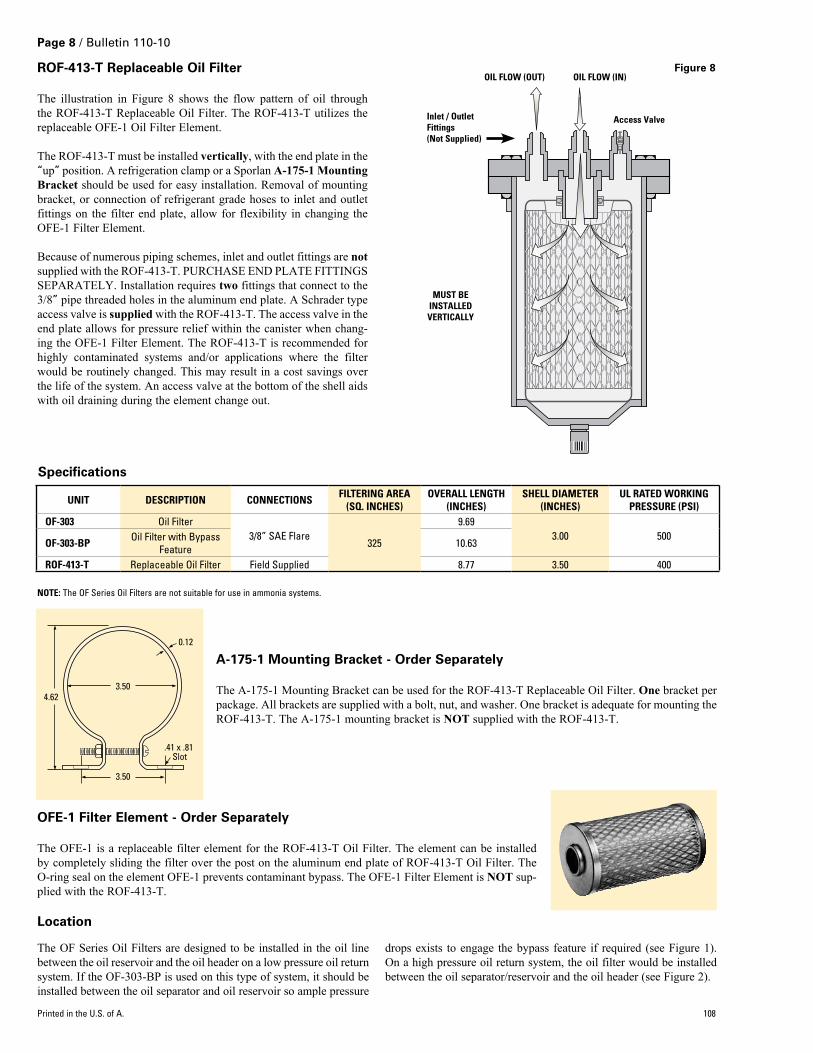
ROF-413-T Replaceable Oil Filter
The illustration in Figure 8 shows the flow pattern of oil through the ROF‑413‑T Replaceable Oil Filter. The ROF‑413‑T utilizes the replaceable OFE‑1 Oil Filter Element.
The ROF‑413‑T must be installed vertically, with the end plate in the “up” position. A refrigeration clamp or a Sporlan A-175-1 Mounting Bracket should be used for easy installation. Removal of mounting bracket, or connection of refrigerant grade hoses to inlet and outlet fittings on the filter end plate, allow for flexibility in changing the OFE‑1 Filter Element.
Because of numerous piping schemes, inlet and outlet fittings are not supplied with the ROF‑413‑T. PURCHASE END PLATE FITTINGS SEPARATELY. Installation requires two fittings that connect to the 3/8” pipe threaded holes in the aluminum end plate. A Schrader type access valve is supplied with the ROF‑413‑T. The access valve in the end plate allows for pressure relief within the canister when chang‑ing the OFE‑1 Filter Element. The ROF‑413‑T is recommended for highly contaminated systems and/or applications where the filter would be routinely changed. This may result in a cost savings over the life of the system. An access valve at the bottom of the shell aids with oil draining during the element change out.
OIL FLOW (IN)OIL FLOW (OUT)
Access ValveInlet / Outlet Fittings (Not Supplied)
MUST BE INSTALLED VERTICALLY
NOTE: The OF Series Oil Filters are not suitable for use in ammonia systems.
The OF Series Oil Filters are designed to be installed in the oil line between the oil reservoir and the oil header on a low pressure oil return system. If the OF‑303‑BP is used on this type of system, it should be installed between the oil separator and oil reservoir so ample pressure
drops exists to engage the bypass feature if required (see Figure 1). On a high pressure oil return system, the oil filter would be installed between the oil separator/reservoir and the oil header (see Figure 2).
A-175-1 Mounting Bracket - Order Separately
The A‑175‑1 Mounting Bracket can be used for the ROF‑413‑T Replaceable Oil Filter. One bracket per package. All brackets are supplied with a bolt, nut, and washer. One bracket is adequate for mounting the ROF‑413‑T. The A‑175‑1 mounting bracket is NOT supplied with the ROF‑413‑T.
.41 x .81 Slot
3.504.62
3.50
0.12
OFE-1 Filter Element - Order Separately
The OFE‑1 is a replaceable filter element for the ROF‑413‑T Oil Filter. The element can be installed by completely sliding the filter over the post on the aluminum end plate of ROF‑413‑T Oil Filter. The O‑ring seal on the element OFE‑1 prevents contaminant bypass. The OFE‑1 Filter Element is NOT sup‑plied with the ROF‑413‑T.
Specifications
Location
Figure 8
Printed in the U.S. of A. 108
UNIT DESCRIpTION CONNECTIONS FILTERING AREA(SQ. INChES)
OVERALL LENGTh(INChES)
ShELL DIAMETER(INChES)
UL RATED WORKING pRESSURE (pSI)
OF-303 Oil Filter3/8” SAE Flare
325
9.693.00 500
OF-303-Bp Oil Filter with Bypass Feature 10.63
ROF-413-T Replaceable Oil Filter Field Supplied 8.77 3.50 400