designing secure multi-tenancy into virtualized data centers · cisco systems, inc., 170 west...
TRANSCRIPT
Designing Secure Multi-Tenancy into Virtualized Data Centers
March 16, 2010
Introduction
Goal of This DocumentCisco, VMware, and NetApp have jointly designed a best in breed Secure Cloud Architecture and have validated this design in a lab environment. This document describes the design of—and the rationale behind—the Secure Cloud Architecture. The design describes includes many issues that must be addressed prior to deployment as no two environments are alike. This document also discusses the problems that this architecture solves and the four pillars of a Secure Cloud environment.
AudienceThe target audience for this document includes, but is not limited to, sales engineers, field consultants, professional services, I.T. managers, partner engineering, and customers who wish to deploy a secure multi-tenant environment consisting of best-of-breed products from Cisco, NetApp, and VMware.
ObjectivesThis document is intended to articulate the design considerations and validation efforts required to design, deploy, and backup a secure multi-tenant virtual IT-as-a-service.
Americas Headquarters:
© 2009 Cisco Systems, Inc. All rights reserved.
Cisco Systems, Inc., 170 West Tasman Drive, San Jose, CA 95134-1706 USA

Introduction
Problem IdentificationToday’s traditional IT model suffers from resources located in different, unrelated silos—leading to low utilization, gross inefficiency, and an inability to respond quickly to changing business needs. Enterprise servers reside in one area of the data center and network switches and storage arrays in another. In many cases, different business units own much of the same type of equipment, use it in much the same way, in the same data center row, yet require separate physical systems in order to separate their processes and data from other groups.
This separation often results in ineffectiveness as well as complicating the delivery of IT services and sacrificing alignment with business activity. As the IT landscape rapidly changes, cost reduction pressures, focus on time to market, and employee empowerment are compelling enterprises and IT providers to develop innovative strategies to address these challenges.
The current separation of servers, networks, and storage between different business units is commonly divided by physical server rack and a separate network. By deploying a secure multi-tenant virtual IT-as-a-service, each business unit benefits from the transparency of the virtual environment as it still “looks and feels” the same as a traditional, all physical topology.
From the end customer viewpoint, each system is still separate with its own network and storage; however the divider is not a server rack, but a secure multi-tenant environment. The servers, networks, and storage are all still securely separated, in some case much more so than a traditional environment.
And finally, when a business unit needs more servers, it simple requires an order to the IT team to “fire off” a few more virtual machines in the existing environment, instead of having to order new physical equipment for every deployment.
Design OverviewCloud computing removes the traditional silos within the data center and introduces a new level of flexibility and scalability to the IT organization. This flexibility addresses challenges facing enterprises and IT service providers that include rapidly changing IT landscapes, cost reduction pressures, and focus on time to market. What is needed is a cloud architecture with the scalability, flexibility, and transparency to enable IT to provision new services quickly and cost effectively by using service level agreements (SLAs) to address IT requirements and policies, meet the demands of high utilization, and dynamically respond to change, in addition to providing security and high performance.
According to National Institute of Standards and Technology (NIST), cloud computing is defined as a model for enabling convenient, on-demand network access to a shared pool of configurable computing resources (e.g., networks, servers, storage, applications, and services) that can be rapidly provisioned and released with minimal management effort or service provider interaction. This cloud model promotes availability and is composed of three service models and four deployment models.
Service Models
• Cloud Software as a Service (SaaS)—The capability provided to the consumer is the ability to use the provider’s applications running on a cloud infrastructure. The applications are accessible from various client devices through a thin client interface, such as a Web browser. The consumer does not manage or control the underlying cloud infrastructure including network, servers, operating systems, storage, or even individual application capabilities, with the possible exception of limited user-specific application configuration settings. A good example of this would be using a Web browser to view email as provided by Microsoft, Yahoo, or Google.
2
Introduction
• Cloud Platform as a Service (PaaS)—The capability provided to the consumer is to deploy onto the cloud infrastructure consumer-created or acquired applications created using programming languages and tools supported by the provider. The consumer does not manage or control the underlying cloud infrastructure including network, servers, operating systems, or storage, but has control over the deployed applications and possibly application hosting environment configurations. A good example of this would be a hosting provider that allows customers to purchase server space for Web pages such as Rackspace or GoDaddy.
• Cloud Infrastructure as a Service (IaaS)—The capability provided to the consumer is to provision processing, storage, networks, and other fundamental computing resources where the consumer is able to deploy and run arbitrary software, which can include operating systems and applications. The consumer does not manage or control the underlying cloud infrastructure, but has control over operating systems, storage, deployed applications, and possibly limited control of select networking components (e.g., host firewalls). This design guide covers this particular service.
Deployment Models
• Private cloud—The cloud infrastructure is operated solely for an organization. It may be managed by the organization or a third party and may exist on premise or off premise.
• Community cloud—The cloud infrastructure is shared by several organizations and supports a specific community that has shared concerns (e.g., mission, security requirements, policy, and compliance considerations). It may be managed by the organizations or a third party and may exist on premise or off premise.
• Public cloud—The cloud infrastructure is made available to the general public or a large industry group and is owned by an organization selling cloud services.
• Hybrid cloud—The cloud infrastructure is a composition of two or more clouds (private, community, or public) that remain unique entities but are bound together by standardized or proprietary technology that enables data and application portability (e.g., cloud bursting for load-balancing between clouds).
Many enterprises and IT service providers are developing cloud service offerings for public and private environments. Regardless of whether the focus is on public or private cloud services, these efforts share several objectives:
• Increase operational efficiency through cost-effective use of expensive infrastructure.
• Drive up economies of scale through shared resourcing.
• Rapid and agile deployment of customer environments or applications.
• Improve service quality and accelerate delivery through standardization.
• Promote green computing by maximizing efficient use of shared resources, lowering energy consumption.
Achieving these goals can have a profound, positive impact on profitability, productivity, and product quality. However, leveraging shared infrastructure and resources in a cloud-services architecture introduces additional challenges, hindering widespread adoption by IT service providers who demand securely isolated customer or application environments but require highly flexible management.
As enterprise IT environments have dramatically grown in scale, complexity, and diversity of services, they have typically deployed application and customer environments in silos of dedicated infrastructure. These silos are built around specific applications, customer environments, business organizations, operational requirements, and regulatory compliance (Sarbanes-Oxley, HIPAA, PCI) or to address specific proprietary data confidentiality. For example:
• Large enterprises need to isolate HR records, finance, customer credit card details, etc.
3
Architecture Overview
• Resources externally exposed for out-sourced projects require separation from internal corporate environments.
• Health care organizations must ensure patient record confidentiality.
• Universities need to partition student user services from business operations, student administrative systems, and commercial or sensitive research projects.
• Telcos and service providers must separate billing, CRM, payment systems, reseller portals, and hosted environments.
• Financial organizations need to securely isolate client records and investment, wholesale, and retail banking services.
• Government agencies must partition revenue records, judicial data, social services, operational systems, etc.
Enabling enterprises to migrate such environments to a cloud architecture demands the capability to provide secure isolation while still delivering the management and flexibility benefits of shared resources. Both private and public cloud providers must enable all customer data, communication, and application environments to be securely separated, protected, and isolated from other tenants. The separation must be so complete and secure that the tenants have no visibility of each other. Private cloud providers must deliver the secure separation required by their organizational structure, application requirements, or regulatory compliance.
However, lack of confidence that such secure isolation can be delivered with resilient resource management flexibility is a major obstacle to the widespread adoption of cloud service models. NetApp, Cisco, and VMware have collaborated to create a compelling infrastructure solution that incorporates comprehensive compute, network, and storage technologies that facilitate dynamic, shared resource management while maintaining a secured and isolated environment. VMware® vSphere, VMware® vShield, Cisco Unified Computing System, Cisco Nexus Switches, Cisco MDS Switches, and NetApp® MultiStore® with NetApp Data Motion™ deliver a powerful solution to fulfill the demanding requirements for secure isolation and flexibility in cloud deployments of all scales.
One of the main differences between traditional shared hosting (internal or external) and a typical IaaS cloud service is the level of control available to the user. Traditional hosting services provide users with general application or platform administrative control, whereas IaaS deployments typically provide the user with broader control over the compute resources. The secure cloud architecture further extends user control end-to-end throughout the environment: the compute platform, the network connectivity, storage resources, and data management. This architecture enables service providers and enterprises to securely offer their users unprecedented control over their entire application environment. Unique isolation technologies combined with extensive management flexibility delivers all of the benefits of cloud computing for IT providers to confidently provide high levels of security and service for multi-tenant customer and consolidated application environments.
Architecture OverviewOne of the essential characteristics of a cloud architecture is the ability to pool resources. The provider’s compute, network, and storage resources are pooled to serve multiple consumers using a multi-tenant model, with different physical and virtual resources dynamically assigned and reassigned according to consumer demand. There is a sense of location independence in that the customer generally has no control or knowledge over the exact location of the provided resources but may be able to specify location at a higher level of abstraction (e.g., country, state, or data center). Examples of resources include storage, processing, memory, network bandwidth, and virtual machines.
4
Architecture Overview
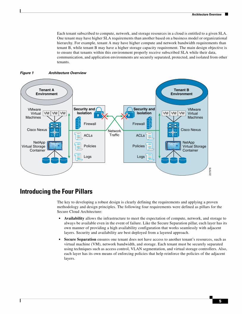
Each tenant subscribed to compute, network, and storage resources in a cloud is entitled to a given SLA. One tenant may have higher SLA requirements than another based on a business model or organizational hierarchy. For example, tenant A may have higher compute and network bandwidth requirements than tenant B, while tenant B may have a higher storage capacity requirement. The main design objective is to ensure that tenants within this environment properly receive subscribed SLA while their data, communication, and application environments are securely separated, protected, and isolated from other tenants.
Figure 1 Architecture Overview
Introducing the Four PillarsThe key to developing a robust design is clearly defining the requirements and applying a proven methodology and design principles. The following four requirements were defined as pillars for the Secure Cloud Architecture:
• Availability allows the infrastructure to meet the expectation of compute, network, and storage to always be available even in the event of failure. Like the Secure Separation pillar, each layer has its own manner of providing a high availability configuration that works seamlessly with adjacent layers. Security and availability are best deployed from a layered approach.
• Secure Separation ensures one tenant does not have access to another tenant’s resources, such as virtual machine (VM), network bandwidth, and storage. Each tenant must be securely separated using techniques such as access control, VLAN segmentation, and virtual storage controllers. Also, each layer has its own means of enforcing policies that help reinforce the policies of the adjacent layers.
Tenant AEnvironment
Tenant BEnvironment
Security andIsolation
Firewall
ACLsNetworkTraffic
VMwareVirtualMachines
NetAppVirtual StorageContainer
Cisco Nexus
Policies
Logs
VM VM VMSecurity and
Isolation
Firewall
ACLs
VMwareVirtual
Machines
NetAppVirtual Storage
Container
Cisco Nexus
Policies
Logs
VM VM VM
2279
78
5

Architecture Overview
• Service Assurance provides isolated compute, network, and storage performance during both steady state and non-steady state. For example, the network can provide each tenant with a certain bandwidth guarantee using Quality of Service (QoS), resource pools within VMware help balance and guarantee CPU and memory resources, while FlexShare can balance resource contention across storage volumes.
• Management is required to rapidly provision and manage resources and view resource availability. In its current form, each layer is managed by vCenter, UCS Manager, DC Network Manager, and NetApp Operations Manager, respectively.
Architecture Components
Figure 2 Architecture Components
Network
Compute/Network
Management
Storage
Cisco Nexus 7000
VMware vCenterCisco UCS ManagerCisco DC Network ManagerNetApp Operations Manager
VMware vShield
VMware vSphere
Cisco UCS 5108Blade Chassis
Cisco UCS 6100Fabric Interconnect
Cisco Nexus 1000V
Cisco Nexus 5000
NetApp Multistore
NetApp FAS Controller
SANCisco MDS 9124
2279
79
6
Architecture Overview
Compute
VMware vSphere and vCenter Server
VMware vSphere and vCenter Server offer the highest levels of availability and responsiveness for all applications and services with VMware vSphere, the industry’s most reliable platform for data center virtualization. Optimize IT service delivery and deliver the highest levels of application service agreements with the lowest total cost per application workload by decoupling your business critical applications from the underlying hardware for unprecedented flexibility and reliability.
VMware vCenter Server provides a scalable and extensible platform that forms the foundation for virtualization management (http://www.vmware.com/solutions/virtualization-management/). VMware vCenter Server, formerly VMware VirtualCenter, centrally manages VMware vSphere (http://www.vmware.com/products/vsphere/) environments, allowing IT administrators dramatically improved control over the virtual environment compared to other management platforms. VMware vCenter Server:
• Provides centralized control and visibility at every level of virtual infrastructure.
• Unlocks the power of vSphere through proactive management.
• Is a scalable and extensible management platform with a broad partner ecosystem.
For more information, see http://www.vmware.com/products/.
VMware vShield
VMware vShield Zones is a centrally managed, stateful, distributed virtual firewall bundled with vSphere 4.0 which takes advantage of ESX host proximity and virtual network visibility to create security zones. The vShield Zones integrates into the VMware vCenter and leverages virtual inventory information, such as vNICs, port groups, clusters, and VLANs, to simplify firewall rule management and trust zone provisioning. By leveraging various VMware logical containers, it is possible to greatly reduce the number of rules required to secure a multi-tenant environment and therefore reduce the operational burden that accompanies the isolation and segmentation of tenants and applications. This new way of creating security policies closely ties to the VMware virtual machine objects and therefore follows the VMs during vMotion and is completely transparent to IP address changes and network re-numbering. Using vShield Zones within DRS (Distributed Resource Scheduler) clusters ensures secure compute load-balancing operations without performance compromise as the security policy follows the virtual machine.
In addition to being an endpoint and asset aware firewall, the vShield Zones contain microflow-level virtual network reporting that is critical to understanding and monitoring the virtual traffic flows and implement zoning policies based on rich information available to security and network administrators. This flow information is categorized into allowed and blocked sessions and can be sliced and diced by protocol, port and application, and direction and seen at any level of the inventory hierarchy. It can be further used to find rogue services, prohibited virtual machine communication, serve as a regulatory compliance visualization tool, and operationally to troubleshoot access and firewall rule configuration. Flexible user configuration allows role-based duty separation for network, security, and vSphere administrator duties.
For more information, see: http://www.vmware.com/products/vshield-zones/.
Cisco UCS and UCSM
The Cisco Unified Computing System™ (UCS) is a revolutionary new architecture for blade server computing. The Cisco UCS is a next-generation data center platform that unites compute, network, storage access, and virtualization into a cohesive system designed to reduce total cost of ownership
7
Architecture Overview
(TCO) and increase business agility. The system integrates a low-latency, lossless 10 Gigabit Ethernet unified network fabric with enterprise-class, x86-architecture servers. The system is an integrated, scalable, multi-chassis platform in which all resources participate in a unified management domain. Managed as a single system whether it has one server or 320 servers with thousands of virtual machines, the Cisco Unified Computing System decouples scale from complexity. The Cisco Unified Computing System accelerates the delivery of new services simply, reliably, and securely through end-to-end provisioning and migration support for both virtualized and nonvirtualized systems.
UCS Components
The Cisco Unified Computing System is built from the following components:
• Cisco UCS 6100 Series Fabric Interconnects (http://www.cisco.com/en/US/partner/products/ps10276/index.html) is a family of line-rate, low-latency, lossless, 10-Gbps Ethernet and Fibre Channel over Ethernet interconnect switches.
• Cisco UCS 5100 Series Blade Server Chassis (http://www.cisco.com/en/US/partner/products/ps10279/index.html) supports up to eight blade servers and up to two fabric extenders in a six rack unit (RU) enclosure.
• Cisco UCS 2100 Series Fabric Extenders (http://www.cisco.com/en/US/partner/products/ps10278/index.html) bring unified fabric into the blade-server chassis, providing up to four 10-Gbps connections each between blade servers and the fabric interconnect.
• Cisco UCS B-Series Blade Servers (http://www.cisco.com/en/US/partner/products/ps10280/index.html) adapt to application demands, intelligently scale energy use, and offer best-in-class virtualization.
• Cisco UCS B-Series Network Adapters (http://www.cisco.com/en/US/partner/products/ps10280/index.html) offer a range of options, including adapters optimized for virtualization, compatibility with existing driver stacks, or efficient, high-performance Ethernet.
• Cisco UCS Manager (http://www.cisco.com/en/US/partner/products/ps10281/index.html) provides centralized management capabilities for the Cisco Unified Computing System.
Fore more information, see: http://www.cisco.com/en/US/partner/netsol/ns944/index.html.
Network
Cisco Nexus 7000
As Cisco’s flagship switching platform, the Cisco Nexus 7000 Series is a modular switching system designed to deliver 10 Gigabit Ethernet and unified fabric in the data center. This new platform delivers exceptional scalability, continuous operation, and transport flexibility. It is primarily designed for the core and aggregation layers of the data center.
The Cisco Nexus 7000 Platform is powered by Cisco NX-OS (http://www.cisco.com/en/US/products/ps9372/index.html), a state-of-the-art operating system, and was specifically designed with the unique features and capabilities needed in the most mission-critical place in the network, the data center.
For more information, see: http://www.cisco.com/en/US/products/ps9402/index.html.
8
Architecture Overview
Cisco Nexus 5000
The Cisco Nexus 5000 Series (http://www.cisco.com/en/US/products/ps9670/index.html), part of the Cisco Nexus Family of data center class switches, delivers an innovative architecture that simplifies data center transformation. These switches deliver high performance, standards-based Ethernet and FCoE that enables the consolidation of LAN, SAN, and cluster network environments onto a single Unified Fabric. Backed by a broad group of industry-leading complementary technology vendors, the Cisco Nexus 5000 Series is designed to meet the challenges of next-generation data centers, including dense multisocket, multicore, virtual machine-optimized deployments, where infrastructure sprawl and increasingly demanding workloads are commonplace.
The Cisco Nexus 5000 Series is built around two custom components: a unified crossbar fabric and a unified port controller application-specific integrated circuit (ASIC). Each Cisco Nexus 5000 Series Switch contains a single unified crossbar fabric ASIC and multiple unified port controllers to support fixed ports and expansion modules within the switch.
The unified port controller provides an interface between the unified crossbar fabric ASIC and the network media adapter and makes forwarding decisions for Ethernet, Fibre Channel, and FCoE frames. The ASIC supports the overall cut-through design of the switch by transmitting packets to the unified crossbar fabric before the entire payload has been received. The unified crossbar fabric ASIC is a single-stage, nonblocking crossbar fabric capable of meshing all ports at wire speed. The unified crossbar fabric offers superior performance by implementing QoS-aware scheduling for unicast and multicast traffic. Moreover, the tight integration of the unified crossbar fabric with the unified port controllers helps ensure low latency lossless fabric for ingress interfaces requesting access to egress interfaces.
For more information, see: http://www.cisco.com/en/US/products/ps9670/index.html.
Cisco Nexus 1000V
The Nexus 1000V (http://www.cisco.com/en/US/products/ps9902/index.html) switch is a software switch on a server that delivers Cisco VN-Link (http://www.cisco.com/en/US/netsol/ns894/index.html) services to virtual machines hosted on that server. It takes advantage of the VMware vSphere (http://www.cisco.com/survey/exit.html?http://www.vmware.com/products/cisco-nexus-1000V/index.html) framework to offer tight integration between server and network environments and help ensure consistent, policy-based network capabilities to all servers in the data center. It allows policy to move with a virtual machine during live migration, ensuring persistent network, security, and storage compliance, resulting in improved business continuance, performance management, and security compliance. Last but not least, it aligns management of the operational environment for virtual machines and physical server connectivity in the data center, reducing the total cost of ownership (TCO) by providing operational consistency and visibility throughout the network. It offers flexible collaboration between the server, network, security, and storage teams while supporting various organizational boundaries and individual team autonomy.
For more information, see: http://www.cisco.com/en/US/products/ps9902/index.html.
Cisco MDS 9124
The Cisco MDS 9124, a 24-port, 4-, 2-, or 1-Gbps fabric switch offers exceptional value by providing ease of use, flexibility, high availability, and industry-leading security at an affordable price in a compact one-rack-unit (1RU) form factor. With its flexibility to expand from 8 to 24 ports in 8-port increments, the Cisco MDS 9124 offers the densities required for both departmental SAN switches and edge switches in enterprise core-edge SANs. Powered by Cisco MDS 9000 SAN-OS Software, it includes advanced storage networking features and functions and provides enterprise-class capabilities for commercial
9
Architecture Overview
SAN solutions. It also offers compatibility with Cisco MDS 9500 Series Multilayer Directors and the Cisco MDS 9200 Series Multilayer Fabric Switches for transparent, end-to-end service delivery in core-edge enterprise deployments.
For more information, see: http://www.cisco.com/en/US/products/hw/ps4159/index.html.
Cisco Data Center Network Manager (DCNM)
DCNM is a management solution that maximizes overall data center infrastructure uptime and reliability, which improves business continuity. Focused on the management requirements of the data center network, DCNM provides a robust framework and rich feature set that fulfills the switching needs of present and future data centers. In particular, DCNM automates the provisioning process.
DCNM is a solution designed for Cisco NX-OS-enabled hardware platforms. Cisco NX-OS provides the foundation for the Cisco Nexus product family, including the Cisco Nexus 7000 Series.
For more information, see: http://www.cisco.com/en/US/docs/switches/datacenter/sw/4_1/dcnm/fundamentals/configuration/guide/fund_overview.html.
Storage
NetApp Unified Storage
The NetApp FAS controllers share a unified storage architecture based on the Data ONTAP® 7G operating system and use an integrated suite of application-aware manageability software. This provides efficient consolidation of SAN, NAS, primary, and secondary storage on a single platform while allowing concurrent support for block and file protocols using Ethernet and Fibre Channel interfaces, including FCoE, NFS, CIFS, and iSCSI. This common architecture allows businesses to start at an entry level storage platform and easily migrate to the higher-end platforms as storage requirements increase, without learning a new OS, management tools, or provisioning processes.
To provide resilient system operation and high data availability, Data ONTAP 7G is tightly integrated to the hardware systems. The FAS systems use redundant, hot-swappable components, and with the patented dual-parity RAID-DP (high-performance RAID 6), the net result can be superior data protection with little or no performance loss. For a higher level of data availability, Data ONTAP provides optional mirroring, backup, and disaster recovery solutions. For more information, see: http://www.netapp.com/us/products/platform-os/data-ontap/.
With NetApp Snapshot technology, there is the added benefit of near-instantaneous file-level or full data set recovery, while using a very small amount of storage. Snapshot creates up to 255 data-in-place, point-in-time images per volume. For more information, see: http://www.netapp.com/us/products/platform-os/snapshot.html.
Important applications require quick response, even during times of heavy loading. To enable fast response time when serving data for multiple applications, FlexShareTM quality of service software is included as part of the Data ONTAP operating system. FlexShare allows storage administrators to set and dynamically adjust workload priorities. For more information, see: http://www.netapp.com/us/products/platform-os/flexshare.html.
While this solution focuses on specific hardware, including the FAS6080, any of the FAS platforms, including the FAS6040, FAS3140, and FAS3170, are supported based on your sizing requirements and expansion needs with all of the same software functionality and features. Similarly, the quantity, size, and type of disks used within this environment may also vary depending on storage and performance needs. Additional add-on cards, such as the Performance Accelerator Modules (PAM II), can be utilized
10
Architecture Overview
in this architecture to increase performance by adding additional system cache for fast data access, but are not required for the Secure Cloud functionality. For more information, see: http://www.netapp.com/us/products.
NetApp MultiStore
NetApp MultiStore allows cloud providers to quickly and easily create separate and completely private logical partitions on a single NetApp storage system as discrete administrative domains called vFiler units. These vFiler units have the effect of making a single physical storage controller appear to be many logical controllers. Each vFiler unit can be individually managed with different sets of performance and policy characteristics. Providers can leverage NetApp MultiStore to enable multiple customers to share the same storage resources with minimal compromise in privacy or security, and even delegate administrative control of the virtual storage container directly to the customer. Up to 130 vFiler units can be created on most NetApp HA pairs using NetApp's MultiStore technology. For more information, see: http://www.netapp.com/us/products/platform-os/multistore.html.
Ethernet Storage
One of the key technologies in this architecture, Ethernet storage using NFS is leveraged to provide tremendous efficiency and functional gains. Some of the key benefits of Ethernet-based storage are:
• Reduced hardware costs for implementation.
• Reduced training costs for support personnel.
• A greatly simplified infrastructure supported by internal IT groups.
The initial solution is to deploy a clustered pair of enterprise class NetApp storage controllers onto a dedicated virtual Ethernet storage network which is hosted by a pair of core IP Cisco switches and an expandable number of edge switches. The virtual Ethernet storage network also extends to each host server through two fabric interconnects enabling direct IP storage access from within the compute layer. For more information, see: http://www.netapp.com/us/company/leadership/ethernet-storage/.
Stateless Computing Using SAN Boot
The deployment of an architecture consisting of SAN booted physical resources provides great flexibility and resiliency to a multi-tenant infrastructure. A SAN booted deployment consists of hosts in the environment having a converged network adapter (CNA) capable of translating SCSI commands via fibre channel or FCoE. Hosts then access their boot OS via logical unit number (LUN) or storage container mapped on an external storage array. This boot methodology can be accomplished with software or hardware initiators and, for the purposes of this document, local HBAs are discussed.
When using NetApp controllers, SAN booted hosts have superior RAID protection and increased performance when compared to traditional local disk arrays. Furthermore, SAN booted resources can easily be recovered, are better utilized, and scale much quicker than local disk installs. Operating systems and hypervisors provisioned via NetApp controllers take advantage of storage efficiencies inherent in NetApp products. Another major benefit of SAN booted architectures is that they can be deployed and recovered in minutes dependent on the OS to be installed.
SAN booted deployments effectively reduce provisioning time, increase utilization, and aide in the stateless nature of service profiles within UCS. A SAN booted environment can be preconfigured and, through the use of NetApp technologies, can perform better, have greater data protection, and be easier to restore.
For more information, see: http://www.netapp.com/us/products.
11
End-to-End Block Diagram
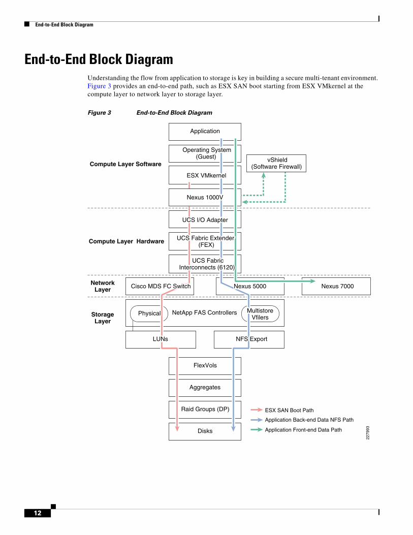
End-to-End Block DiagramUnderstanding the flow from application to storage is key in building a secure multi-tenant environment. Figure 3 provides an end-to-end path, such as ESX SAN boot starting from ESX VMkernel at the compute layer to network layer to storage layer.
Figure 3 End-to-End Block Diagram
Application
NetApp FAS Controllers
FlexVols
Raid Groups (DP)
Aggregates
Disks
Nexus 7000
ESX SAN Boot Path
Application Front-end Data Path
Application Back-end Data NFS Path
Compute Layer Software
Compute Layer Hardware
NetworkLayer
StorageLayer
ESX VMkernel
Nexus 5000
UCS FabricInterconnects (6120)
Operating System(Guest) vShield
(Software Firewall)
Nexus 1000V
UCS I/O Adapter
UCS Fabric Extender (FEX)
NFS ExportLUNs
MultistoreVfilers
Physical
Cisco MDS FC Switch
2279
93
12
Logical Topology
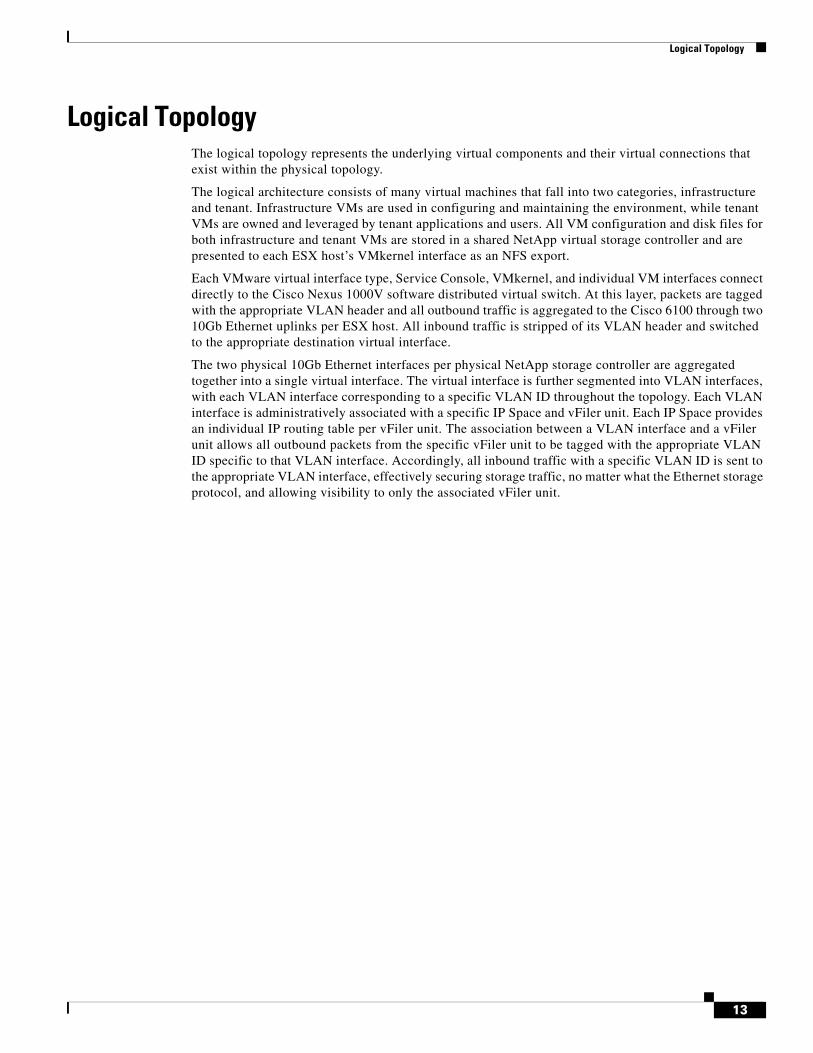
Logical TopologyThe logical topology represents the underlying virtual components and their virtual connections that exist within the physical topology.
The logical architecture consists of many virtual machines that fall into two categories, infrastructure and tenant. Infrastructure VMs are used in configuring and maintaining the environment, while tenant VMs are owned and leveraged by tenant applications and users. All VM configuration and disk files for both infrastructure and tenant VMs are stored in a shared NetApp virtual storage controller and are presented to each ESX host’s VMkernel interface as an NFS export.
Each VMware virtual interface type, Service Console, VMkernel, and individual VM interfaces connect directly to the Cisco Nexus 1000V software distributed virtual switch. At this layer, packets are tagged with the appropriate VLAN header and all outbound traffic is aggregated to the Cisco 6100 through two 10Gb Ethernet uplinks per ESX host. All inbound traffic is stripped of its VLAN header and switched to the appropriate destination virtual interface.
The two physical 10Gb Ethernet interfaces per physical NetApp storage controller are aggregated together into a single virtual interface. The virtual interface is further segmented into VLAN interfaces, with each VLAN interface corresponding to a specific VLAN ID throughout the topology. Each VLAN interface is administratively associated with a specific IP Space and vFiler unit. Each IP Space provides an individual IP routing table per vFiler unit. The association between a VLAN interface and a vFiler unit allows all outbound packets from the specific vFiler unit to be tagged with the appropriate VLAN ID specific to that VLAN interface. Accordingly, all inbound traffic with a specific VLAN ID is sent to the appropriate VLAN interface, effectively securing storage traffic, no matter what the Ethernet storage protocol, and allowing visibility to only the associated vFiler unit.
13
Logical Topology
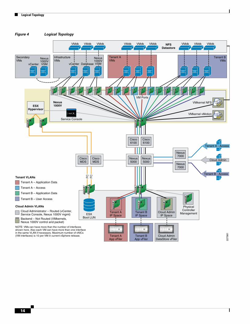
Figure 4 Logical Topology
Tenant A – Application Data
Tenant A – Access
Tenant B – Application Data
Tenant B – User Access
Cloud Admin VLANs
Tenant VLANs
Cloud Administrator – Routed (vCenter, Service Console, Nexus 1000V mgmt)
Backend – Not Routed (VMkernels,Nexus 1000V control and packet)
NOTE: VMs can have more than the number of interfacesshown here. Also each VM can have more than one interfacein the same VLAN if necessary. Maximum number of vNICs(VM interfaces) is 10 per VM in current vSphere release.
Tenant A - Access
Cloud Admin
Tenant B - Access
Nexus7000
Nexus7000
PhysicalController
Management
Nexus5000
Nexus5000
Cisco6100
Cisco6100
CiscoMDS
ESXBoot LUN
CiscoMDS
Tenant BIP Space
Cloud AdminIP Space
Tenant AIP Space
Tenant BApp vFiler
Cloud AdminDataStore vFiler
Tenant AApp vFiler
Tenant AVMs
Tenant BVMs
InfrastructureVMs
FAS3170FAS3170 FAS3170FAS3170 FAS3170FAS3170
FC
FC
ESXHypervisor
Nexus1000V
NFSDatastore
Service Console
VMkernel NFS
VMkernel vMotion
SecondaryVMs
VMdk VMdk VMdk VMdk VMdk VMdk VMdk VMdk VMdk
VM Ports
vCenter DatabasevCenter
Nexus1000VVSM
Nexus1000VVSM
2279
81
14
Design Considerations—The Four Pillars
Design Considerations—The Four PillarsThis section discusses design considerations for the four pillars:
• Availability
• Secure Separation
• Service Assurance
• Management
AvailabilityAvailability is the first pillar and foundation for building a secure multi-tenant environment. Eliminating planned downtime and preventing unplanned downtime are key aspects in the design of the multi-tenant shared services infrastructure. This section covers availability design considerations and best practices related to compute, network, and storage. See Table 1 for various methods of availability.
Highly Available Physical Topology
At the compute layer, Cisco UCS provides unified compute environment with integrated management and networking to support compute resources. VMware vSphere, vShield, vCenter, and Cisco Nexus 1000V builds the virtualized environment as a logical overlay within UCS. All UCS B-Series blade servers can be configured as a single vSphere ESX cluster, enabled with VMware HA for protection against hardware and virtual machine guest operating system failures. vCenter Server Heartbeat offers protection of vCenter against both hardware and application outage. vMotion and Storage vMotion can be used to provide continuous availability to both infrastructure and tenant virtual machines during planned outages. Last but not least, built-in backup feature in vShield Manager protects the secure isolation policies defined for the entire infrastructure.
At the network layer, three tier architecture is enabled with Nexus 5000 as an unified access layer switch and Nexus 7000 as an virtualized aggregation layer switch. The two UCS 6120 Fabric Interconnects with dual-fabric topology enables 10G compute layer. With dual-fabric topology at the edge layer, the vPC topology with redundant chassis, card, and links with Nexus 5000 and Nexus 7000 provides loopless topology.
Table 1 Methods of Availability
Compute Network Storage
• UCS Dual Fabric Redundancy
• vCenter Heartbeat
• VMware HA
• vMotion
• Storage vMotion
• vShield Manager built-in backup
• EtherChannel
• vPC
• Device/Link Redundancy
• MAC Learning
• Active/Passive VSM
• RAID-DP
• Virtual Interface (VIF)
• NetApp HA
• Snapshot
• SnapMirror and SnapVault
15
Design Considerations—The Four Pillars
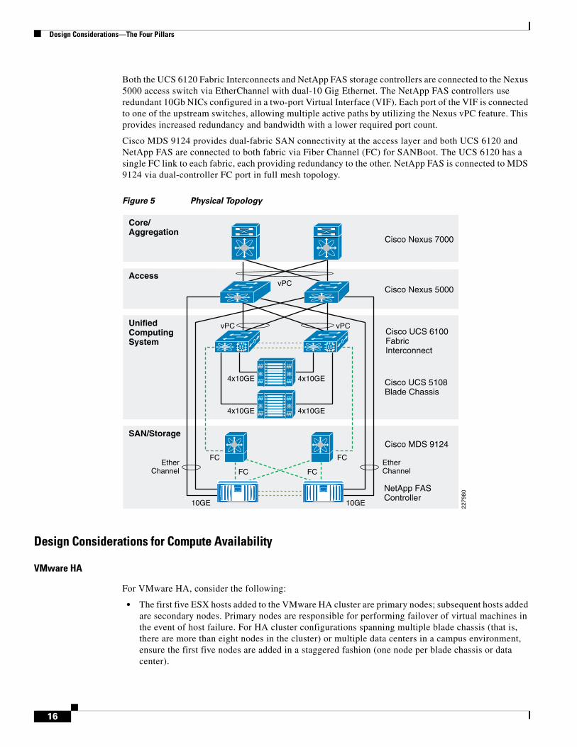
Both the UCS 6120 Fabric Interconnects and NetApp FAS storage controllers are connected to the Nexus 5000 access switch via EtherChannel with dual-10 Gig Ethernet. The NetApp FAS controllers use redundant 10Gb NICs configured in a two-port Virtual Interface (VIF). Each port of the VIF is connected to one of the upstream switches, allowing multiple active paths by utilizing the Nexus vPC feature. This provides increased redundancy and bandwidth with a lower required port count.
Cisco MDS 9124 provides dual-fabric SAN connectivity at the access layer and both UCS 6120 and NetApp FAS are connected to both fabric via Fiber Channel (FC) for SANBoot. The UCS 6120 has a single FC link to each fabric, each providing redundancy to the other. NetApp FAS is connected to MDS 9124 via dual-controller FC port in full mesh topology.
Figure 5 Physical Topology
Design Considerations for Compute Availability
VMware HA
For VMware HA, consider the following:
• The first five ESX hosts added to the VMware HA cluster are primary nodes; subsequent hosts added are secondary nodes. Primary nodes are responsible for performing failover of virtual machines in the event of host failure. For HA cluster configurations spanning multiple blade chassis (that is, there are more than eight nodes in the cluster) or multiple data centers in a campus environment, ensure the first five nodes are added in a staggered fashion (one node per blade chassis or data center).
Core/Aggregation
Access
UnifiedComputingSystem
SAN/Storage
Cisco Nexus 7000
Cisco Nexus 5000
10GE
4x10GE
4x10GE
4x10GE
4x10GE
FC FC
vPC
vPCvPC
FC FCEtherChannel
EtherChannel
10GE
Cisco UCS 6100FabricInterconnect
Cisco UCS 5108Blade Chassis
Cisco MDS 9124
NetApp FASController
2279
80
16
Design Considerations—The Four Pillars
• With ESX 4.0 Update 1, the maximum number of virtual machines for an eight-node VMware HA cluster is 160 per host, allowing for a maximum of 1280 virtual machines per cluster. If the cluster consists of more than eight nodes, the maximum number of virtual machines supported for failover is 40 per host.
• Host Monitoring can be disabled during network maintenance to prevent against “false positive” virtual machine failover.
• Use the “Percentage of cluster resources reserved as failover spare capacity” admission control policy as tenant virtual machines may have vastly different levels of resource reservations set. Initially, a Cloud administrator can set the failover capacity of 25%. As the environment reaches steady state, the percentage of resource reservation can be modified to a value that is greater than or equal to the average resource reservation size or amount per ESX host.
• A virtual machine’s restart priority in the event of ESX Server host failure can be set based on individual tenant SLAs.
• Virtual machine monitoring sensitivity can also be set based on individual tenant SLAs.
VMware vShield
For VMware vShield:
• The vShield virtual machine on each ESX host should have the “virtual machine restart priority” setting of “disabled” as an instance of vShield running on another ESX host will take over the policy enforcement for the virtual machines after HA failover automatically.
Design Considerations for Network Availability
Hierarchical Design
For more information on IP infrastructure high availability best practices, see: http://www.cisco.com/en/US/docs/solutions/Enterprise/Data_Center/DC_3_0/DC-3_0_IPInfra.html
This design guide addresses the components required to build a highly-available, multi-tenant, virtualized infrastructure. This document does not detail the end-to-end aspects of availability. The underlying assumption is that a highly-available infrastructure is the fundamental backbone of any multi-tenant virtualization service. The key design attributes of this adaptation for multi-tenant are described below, including newer design options based on Nexus 1000V capabilities.
The infrastructure design for multi-tenant is based on a three-tier core, aggregation, and access model as described in Figure 5.
Data center technologies are changing at a rapid pace. Cisco network platforms enable the consolidation of various functions at each layer and access technology, creating a single platform for optimized resources utilization. From a hierarchical perspective, there are two consolidation alternatives:
• Aggregation layer—Traditionally the aggregation layer is designed with a physical pair of hardware devices, enabling network connectivity at various speeds and functionality. With the Nexus 7000, the Virtual Device Context capability enables the consolidation of multiple aggregations topologies, with multiple distribution blocks represented as a logical entry in a single pair of Nexus 7000 devices. VDC-level separation is desirable because:
– Compliance-level separation is required at the aggregation layer.
– Explicit operational requirements, such HSRP control, active/active, site specific topologies, and burn in address (BIA) requirements for specific access layer devices.
17
Design Considerations—The Four Pillars
– Separation of user space application separation against control (vMotion) and network management (SNMP, access to non-routed network, etc.).
This design option is not described in detail in this document.
• Access layer—The second consolidation is at the access layer, which presents the most challenging integration requirements with a diverse set of devices. The access layer consists of server, storage, and network endpoints. The goal is to consolidate and unify the access layer with existing access layer topologies and connectivity types. The unification of the access layer needs to address the following diverse connectivity types:
– Separate data access layer for class of network—Application, departmental segregation, functions (backup, dev-test)
– Separate FC (Fiber Channel), NFS (Networked File System), and Tape Back storage topologies and access network
– Edge-layer networking—Nexus 1000V, VBS (Virtual Blade Servers), blade-systems, and stand-alone (multi-NIC) connectivity
– 100 M, 1G, and 10 G speed diversity
– Cabling plant—EOR (end of row) and TOR (top of rack)
This design mainly focuses on the consolidation of compute resources enabled via UCS and storage integration with NFS. The remainder of the topology and its integration are beyond the scope of this document. Consolidation at the access layer requires a design consisting of these key attributes:
• Consolidation and integration of various data networks topologies
• Unified uplink—10Gbps infrastructure for aggregated compute function (more VMs pushing more data)
• Consolidation and integration of storage devices integrated with Ethernet based topologies
Storage topology consolidation is one of the main drivers for customers to consider adopting unified access at the compute level. The consolidation of storage topologies into the existing Ethernet IP data infrastructure requires assurance and protection of storage traffic in term of response time as well as bandwidth. The rest of this section describes the network availability and design attributes for two distinct section of unified access:
Access Layer Availability
Access layer is designed with the following key design attributes in Nexus 5000:
• Enables loop-less topology via Virtual Port-Channel (vPC) technology. The two-tier vPC design is enabled such that all paths from end-to-end are available for forwarding (see Figure 5).
• Nexus 7000 to Nexus 5000 is connected via a single vPC between redundant devices and links. In this design four 10Gbps links are used, however for scalability one can add up to eight vPC member in current Nexus software release.
• The design recommendation is that any edge layer devices should be connected to Nexus 5000 with port-channel configuration.
• The details regarding the configuration and options to enable vPC can be found at: http://www.cisco.com/en/US/prod/collateral/switches/ps9441/ps9670/configuration_guide_c07-543563.html.
• RPVST+ is used as spanning tree protocol. MST option can be considered based on multi-tenant scalability requirements. Redundant Nexus 7000 is the primary and secondary root for all VLANs with matching redundant default gateway priority.
18
Design Considerations—The Four Pillars
Edge Device Layer Availability
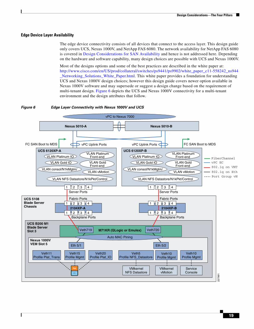
The edge device connectivity consists of all devices that connect to the access layer. This design guide only covers UCS, Nexus 1000V, and NetApp FAS 6080. The network availability for NetApp FAS 6080 is covered in Design Considerations for SAN Availability and hence is not addressed here. Depending on the hardware and software capability, many design choices are possible with UCS and Nexus 1000V.
Most of the designs options and some of the best practices are described in the white paper at: http://www.cisco.com/en/US/prod/collateral/switches/ps9441/ps9902/white_paper_c11-558242_ns944_Networking_Solutions_White_Paper.html. This white paper provides a foundation for understanding UCS and Nexus 1000V design choices; however this design guide covers newer option available in Nexus 1000V software and may supersede or suggest a design change based on the requirement of multi-tenant design. Figure 6 depicts the UCS and Nexus 1000V connectivity for a multi-tenant environment and the design attributes that follow.
Figure 6 Edge Layer Connectivity with Nexus 1000V and UCS
vPC Uplink PortsFC SAN Boot to MDS vPC Uplink Ports
UCS 5108Blade ServerChassis
Eth 5/1 Eth 5/2
Veth720
ServiceConsole
VMkernelNFS Datastore
UCS 6120XP-A
Fabric Ports Fabric Ports
Backplane Ports Backplane Ports
Server Ports Server Ports
Veth11Profile Plat_Trans
Veth20Profile Plat_IO
Veth15Profile Mgmt
2104XP-A
Veth5Profile NFS_Datastore
M71KR (QLogic or Emulex)
Veth10Profile Mgmt
VMkernelvMotion
UCS B200 M1Blade ServerSlot 3
Nexus 1000VVEM Slot 5
Veth10Profile Mgmt
VLAN NFS Datastore/N1kPkt/Control
VLAN Platinum IO
VLAN consol/N1kMgtm/VLAN vMotion
VLAN Gold IO VLAN GoldFront-end
VLAN PlatinumFront-end
UCS 6120XP-B
Nexus 5010-A Nexus 5010-B
VLAN NFS Datastore/N1kPkt/Control
VLAN Platinum IO
VLAN consol/N1kMgtm/VLAN vMotion
VLAN Gold IO VLAN GoldFront-end
VLAN PlatinumFront-end
Auto MAC Pining
vPC to Nexus 7000
1 2 3 4
1 2 3 4
Veth719
2104XP-B1 2 3 4
1 2 3 4
1 2 3 4 1 2 3 4
FC SAN Boot to MDS
2279
91
802.1q on Eth
Port Group vN
802.1q on VNTa
vPC EC FiberChannel
19
Design Considerations—The Four Pillars
Unified Computing Systems:
• Fabric Availability—The UCS provides two completely independent fabric paths A and B. The fabric failover is handled at the Nexus 1000V level and thus not used in this design.
• Control Plane Availability—The UCS 6100 is enabled in active/standby mode for the control plane (UCS Manager) managing the entire UCS systems.
• Forwarding Path Availability—Each fabric interconnect (UCS 6100) is recommended to be configured in end-host mode. Two uplinks from each UCS 6100 are connected as port-channel with LACP “active-active” mode to Nexus 5000.
• Blade Server Path Availability—Each blade server is enabled with M71KR CNA (converge network adaptor) providing 10Gbps connectivity to each fabric.
Nexus 1000V:
• Supervisor Availability—The VSM (Virtual Supervisor Module) is a virtual machine which can be deployed in variety of ways. In this design guide, it is deployed under UCS blade along with VEM (Virtual Ethernet Module). Nexus 1000V supports redundant VSM (Virtual Supervisor Module). The active and standby are recommended to be configured under separate UCS blade server with the anti-affinity rule under vCenter such that both VSM can never be operating under the same blade server.
• Forwarding Path Availability—Each ESX host runs a VEM, which is typically is configured with two uplinks connected to 10Gbp interface of the blade server. When installed and provisioned via vCenter, the port-profile designated for uplinks automatically creates port-channel interface for each ESX host. The sample port-profile reflecting the above connectivity is shown below:
port-profile type ethernet system-uplink description system profile for critical ports vmware port-group switchport mode trunk switchport trunk allowed vlan 125-130,155,200-203,300-303,400-403,900-901 channel-group auto mode on mac-pinning no shutdown system vlan 155,900 state enabled
Notice below that port-channel is inheriting the system-uplink profile and associated ESX host or VEM module.
interface port-channel1 inherit port-profile system-uplink sc-n1kv-1# sh port-channel su Flags: D - Down P - Up in port-channel (members) I - Individual H - Hot-standby (LACP only) s - Suspended r - Module-removed S - Switched R - Routed U - Up (port-channel) -------------------------------------------------------------------------------- Group Port- Type Protocol Member Ports Channel -------------------------------------------------------------------------------- 1 Po1(SU) Eth NONE Eth3/1(P) Eth3/2(P)
The channel-group auto mode on mac-pinning is a new command which is available in Nexus 1000V 4.0(4)SV1(2) release. This feature creates the port-channel which does not run LACP and is not treated as host vPC as in previous release. This feature creates the source-mac based bonding to
20
Design Considerations—The Four Pillars
one of the uplinks and silently drops packet on other links for any packet with source MAC on that link. As a reminder the Nexus 1000V does not run spanning-tree protocol and thus a technique is needed to make MAC address available via single path.
The system vlan command is a critical configuration command that is required to be enabled on set of VLANs. A system VLAN is a VLAN on a port that needs to be brought up before the VEM contacts the VSM. Specifically, this includes the Control/Packet VLANs on the appropriate uplink(s), which is required for the VSM connectivity. It also applies for the ESX management (service console) VLAN on the uplink and if the management port is on Nexus 1000V: if any reason due the failure, these VLANs should come up on the specified ports first, to establish vCenter connectivity and receive switch configuration data. On the ESX host where the VSM is running, if the VSM is running on the VEM, the storage VLAN also needs to be a system VLAN on the NFS VMkernel port.
• Virtual Machine Network Availability—The port-profile capability of Nexus 1000V enables the seamless network connectivity across the UCS domain and ESX cluster. In this design guide, each virtual machine is enabled with three virtual interfaces each inheriting a separate profile. The profiles are designed with connectivity requirements and secure separation principles discussed in Design Considerations for Network Separation. The front-end, back-end, and VM/application management function and traffic flow are separated with distinct traffic profile. The sample profile for a service level of platinum is shown below (the profile names in the figure are shortened to accommodate other connectivity):
port-profile type vethernet Plat_Transactional vmware port-group switchport mode access switchport access vlan 126 service-policy type qos input Platinum_CoS_5 pinning id 0 no shutdown state enabled port-profile type vethernet Plat_IO vmware port-group switchport mode access switchport access vlan 301 service-policy type qos input Platinum_CoS_5 pinning id 1 no shutdown state enabled
The two commands pinning id and services-policy are important in developing services levels for multi-tenant design. Their usage is described in relevant sections that follow.
Design Considerations for SAN Availability
Some issues to consider when designing a fibre channel SAN booted fabric include, but are not limited to, virtual SANs (VSANs), zone configurations, n-port virtualization, fan in/fan out ratios, high availability, and topology size. Each of these components, when not configured correctly, can lead to a fabric that is not highly available due to fibre channel requiring a loss-less nature. In this multi-tenant architecture, an improperly configured SAN impacts the boot OS and in turn tenant VMs and data sets. A basic understanding of fibre channel fabrics is required for design of the SAN booted environment.
Cisco VSANs are a form of logically partitioning a physical switch to segment traffic based on design needs. By deploying VSANs, an administrator can separate primary boot traffic from secondary traffic, ensuring reliability and redundancy. Additionally, as deployments grow, subsequent resources can be placed in additional VSANs to further aide in any segmentation needs from a boot or data access perspective. For instance, as a mutli-tenant environment grows beyond the capacity of a single UCSM,
21
Design Considerations—The Four Pillars
additional SAN booted hosts can be added without impacting existing compute blades or deploying new switches dependent upon port counts. Furthermore, the use of interVSAN routing or IVR enables and administrator to securely and logically associate resources even if they are not in the same VSAN.
Zoning within a fabric is used to prevent extraneous interactions between hosts and storage ports which can lead to very “chatty” fabric in which there is an abundance of initiator cross-talk. Through the creation of zones which exist in a given VSAN, a single port of an initiator can be grouped with the desired storage port to increase security, improve performance, and aid with the troubleshooting of the fabric. A typical SAN booted architecture consists of redundant fabrics (A and B) with primary and secondary boot paths constructed via zones in each fabric.
Traditionally as SANs grow, the switches required increases to accommodate the port count needed. This is particularly true in legacy bladecenter environments as each fibre channel I/O module would constitute another switch to be managed with its own security implications. Additionally, from a performance perspective, this is a concern as each switch or VSAN within an environment has its own domain ID, adding another layer of translation. N-port ID Virtualization or NPIV is a capability of the fibre channel protocol that allows multiple N-ports to share a single physical port. NPIV is particularly powerful in large SAN environments as hosts that log into an NPIV-enabled device would actually be presented directly to the north-bound fabric switch. This improves performance and ease of management. NPIV is a component of the Fabric Interconnect within a UCS deployment and a requirement of any northbound FC switch.
The fan-in characteristics of a fabric is defined as the ratio of host ports that connect to a single target port while fan-out is the ratio of target ports or LUNs that are mapped to a given host. Both are performance indicators, with the former relating to host traffic load per storage port and the latter relating storage load per host port. The optimum ratios for fan-in and fan-out are dependent on the switch, storage array, HBA vendor, and the performance characteristics of IO workload.
High availability within a FC fabric is easily attainable via the configuration of redundant paths and switches. A given host is deployed with a primary and redundant initiator port which is connected to the corresponding fabric. With a UCS deployment, a dual port mezzanine card is installed in each blade server and a matching vHBA and boot policy are setup providing primary and redundant access to the target device. These ports access the fabric interconnect as N-ports which are passed along to a northbound FC switch. Zoning within the redundant FC switches is done such that if one link fails then the other handles data access. Multipathing software is installed dependent on the operating system which ensures LUN consistency and integrity.
When designing SAN booted architectures, considerations are made regarding the overall size and number of hops that an initiator would take before it is able to access its provisioned storage. The fewer hops and fewer devices that are connected across a given interswitch link, the greater the performance of a given fabric. A common target ratio of hosts across a given switch link would be between 7:1 or 10:1, while an acceptable ratio may be as high as 25:1. This ratio can vary greatly depending on the size of the architecture and the performance required.
SAN Connectivity should involve or include:
• The use of redundant VSANs and associated zones
• The use of redundant interswitch links ISLs where appropriate
• The use of redundant target ports
• The use of redundant fabrics with failover capability for fiber channel SAN booted infrastructure
22
Design Considerations—The Four Pillars
Design Considerations for Storage Availability
Data Availability with RAID Groups and Aggregates
RAID groups are the fundamental building block when constructing resilient storage arrays containing any type of application data set or virtual machine deployment. There exists a variety of levels of protection and costs associated with different RAID groups. A storage controller that offers superior protection is an important consideration to make when designing a multi-tenant environment as hypervisor boot, guest VMs, and application data sets are all deployed on a a shared storage infrastructure. Furthermore, the impact of multiple drive failures is magnified as disk size increases. Deploying a NetApp storage system with RAID DP offers superior protection coupled with an optimal price point.
RAID-DP is a standard Data ONTAP feature that safeguards data from double disk failure by means of using two parity disks. With traditional single-parity arrays, adequate protection is provided against a single failure event such as a disk failure or error bit error during a read. In either case, data is recreated using parity and data remaining on unaffected disks. With a read error, the correction happens almost instantaneously and often the data remains online. With a drive failure, the data on the corresponding disk has to be recreated, which leaves the array in a vulnerable state until all data has been reconstructed onto a spare disk. With a NetApp array deploying RAID-DP, a single event or second event failure is survived with little performance impact as there exists a second parity drive. NetApp controllers offer superior availability with less hardware to be allocated.
Aggregates are concatenations of one or more RAID groups that are then partitioned into one or more flexible volumes. Volumes are shared out as file level (NFS or CIFS) mount points or are further allocated as LUNs for block level (iSCSI or FCP) access. With NetApp’s inherent storage virtualization, all data sets or virtual machines housed within a shared storage infrastructure take advantage of RAID-DP from a performance and protection standpoint. For example, with a maximum UCS deployment there could exist 640 local disks (two per blade) configured in 320 independent RAID-1 arrays all housing the separate hypervisor OS. Conversely, using a NetApp array deploying RAID-DP, these OSes could be within one large aggregate to take advantage of pooled resources from a performance and availability perspective.
Highly Available Storage Configurations
Much as an inferior RAID configuration is detrimental to data availability, the overall failure of the storage controller serving data can be catastrophic. Combined with RAID-DP, NetApp HA pairs provide continuous data availability for multi-tenant solutions. The deployment of an HA pair of NetApp controllers ensures the availability of the environment both in the event of failure and in the event of upgrades.
Storage controllers in an HA pair have the capability to seamlessly take over its partner’s roles in the event of a system failure. These include controller personalities, IP addresses, SAN information, and access to the data being served. This is accomplished using cluster interconnections, simple administrative setup, and redundant paths to storage. In the event of an unplanned outage, a node assumes the identity of its partner with no reconfiguration required by any associated hosts. HA pairs also allow for non-disruptive upgrades for software installation and hardware upgrades. A simple command is issued to takeover and giveback identity.
The following considerations should be made when deploying an HA pair:
• Best practices should be deployed to ensure any one node can handle the total system workload.
• Storage controllers communicate heartbeat information using a cluster interconnect cable.
• Takeover process takes seconds.
23
Design Considerations—The Four Pillars
• TCP sessions to client hosts are re-established following a timeout period.
• Some parameters must be configure identically on partner nodes.
For additional information regarding NetApp HA pairs, see: http://media.netapp.com/documents/clustered.pdf.
Storage Network Connectivity (VIFs) using LACP
NetApp provides three types of Virtual Interfaces (VIFs) for network port aggregation and redundancy:
• SingleMode
• Static MultiMode
• Dynamic MultiMode
The Secure Cloud environment uses Dynamic MultiMode VIFs due to the increased reliability and error reporting, as well as compatibility with Cisco Virtual Port Channels. A Dynamic MultiMode VIF uses Link Aggregation Control Protocol (LACP) to group multiple interfaces together to act as a single logical link. This provides intelligent communication between the storage controller and the Cisco Nexus allowing for load balancing across physical interfaces as well as failover capabilities.
Storage Backup and Restoration
NetApp storage controllers support various mechanisms for backup and restoration of data, which is of particular importance in a multi-tenant architecture consisting of shared infrastructure. This section discusses the concepts supported by Data ONTAP with respect to data retention and recovery. It should be noted that existing backup solutions are often in place and the NetApp software suite offers seamless integration for many of these applications. In light of this, the following section illustrates the options and flexibility available in backing up and restoring files, volumes, and aggregates.
The primary methods available from NetApp to backup, replicate, and restore data in the Secure Cloud are as follows:
• Snapshots (Aggregate and Volume level) and SnapRestores of the primary file system
• SnapMirror and SnapVault
Snapshots
Aggregate snapshots provide a point-in-time view of all data within an entire aggregate including all contained flexible volumes. A restoration of an aggregate snapshot restores all data in all flexible volumes contained within that aggregate to the same point-in-time, overwriting the existing data.
Volume-Based Snapshots are taken at the volume level, as the associated applications are contained within a volume. Here are some considerations to be made for Volume Snapshots:
• There can only be 255 active snapshots in a volume.
• The snapshot is read-only. Snapshots are scheduled on the primary copy of the data.
• All efforts should be made to ensure data is in a consistent state before creating a snapshot.
• Snapshot Autodelete can be configured to remove older Snapshots to save space.
• Application owners can view their own read-only Snapshots.
• Snapshots can easily be backed up to tape or virtual tape.
Snapshots can be triggered by a number of means; the primary methods are:
• Scheduled snapshots (asynchronous), setup by the storage administrator.
24
Design Considerations—The Four Pillars
• Remote authenticated Snapshots using ZAPI (an XML protocol over HTTPS).
• Isolated Snapshots by Proxy Host on a per-application basis.
SnapMirror and SnapVault
SnapMirror is replication software intended for disaster recovery solutions or for the replication of volumes to additional controllers or vFiler units. The mirror is an exact replica of data on the primary storage, including all the local Snapshot copies, and can be mounted read-write to recover from failure. If a Snapshot backup is deleted on the source, it goes away on the mirror at the next replication. Here are some considerations to be made:
• A SnapMirror can easily be backed up to tape/virtual tape.
• A SnapMirror provides a means to perform a remote enterprise-wide online backup.
• SnapMirrors can be mounted read-write for failover or maintenance of the primary system.
SnapVault, in contrast, is intended for disk-to-disk backup. A separate Snapshot retention policy is specified for the target environment, allowing long-term archiving of Snapshot backups on secondary storage. Secondary copies managed only by SnapVault cannot be mounted read-write. Backups must be recovered from secondary storage to the original or to an alternative primary storage system in order to restart.
Like SnapMirror, SnapVault can easily be backed up to tape or virtual tape. Here are some considerations to be made in regards to SnapVault:
• SnapVault can be used in conjunction with SnapMirror for a multi-tiered archive workflow.
• SnapVault can not be mounted read-write as it only stores block-level changes of Snapshots.
Secure SeparationThe second pillar, secure separation, is the partition that prevents one customer from having access to another’s environment, nor does a tenant have access to the administrative features of the cloud infrastructure. When a tenant is provisioned, his or her environment is equipped with:
• One or more virtual machines (VMs) or vApps
• One or more virtual storage controllers (vFiler units)
• One or more VLANs to interconnect and access these resources
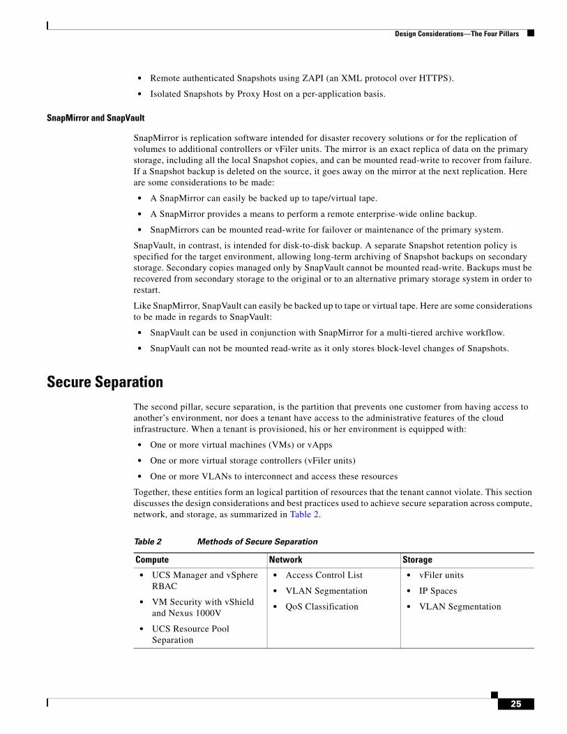
Together, these entities form an logical partition of resources that the tenant cannot violate. This section discusses the design considerations and best practices used to achieve secure separation across compute, network, and storage, as summarized in Table 2.
Table 2 Methods of Secure Separation
Compute Network Storage
• UCS Manager and vSphere RBAC
• VM Security with vShield and Nexus 1000V
• UCS Resource Pool Separation
• Access Control List
• VLAN Segmentation
• QoS Classification
• vFiler units
• IP Spaces
• VLAN Segmentation
25
Design Considerations—The Four Pillars
Design Considerations for Access Control
In order to secure a multi-tenant environment, it is imperative to properly plan and design access control methods. This section discusses access control using:
• Role-based access control (RBAC) for UCS, vCenter, and NetApp
• Access Control List (ACL) for Cisco Nexus switches
Role-Based Access Control (RBAC) using UCS Manager, vCenter, and NetApp
The UCS Manager offers role-based management that helps organizations make more efficient use of their limited administrator resources. Cisco UCS Manager allows organizations to maintain IT disciplines while improving teamwork, collaboration, and overall effectiveness. Server, network, and storage administrators maintain responsibility and accountability for their domain policies within a single integrated management environment. Compute infrastructure can now be provisioned without the time-consuming manual coordination between multiple disciplines previously required. Roles and privileges in the system can be easily modified and new roles quickly created.
Administrators focus on defining policies needed to provision compute infrastructure and network connectivity. Administrators can collaborate on strategic architectural issues and implementation of basic server configuration can now be automated. Cisco UCS Manager supports multi-tenant service providers and enterprise data centers serving internal clients as separate business entities. The system can be logically partitioned and allocated to different clients or customers to administer as their own.
In UCS Manager, Role Based Access Control (RBAC) is a method of restricting or authorizing system access for users based on “roles” and “locales”. A role can contain one or more system privileges where each privilege defines an administrative right to a certain object or type of object in the system. By assigning a user a role, the user inherits the capabilities of the privileges defined in that role. For example, for a server role, responsibilities may include provisioning blades and privileges may include creating, modifying, and deleting service profiles.
UCS Manager supports the creation of local users in the UCSM database as well as the integration of name services such as LDAP, RADIUS, and TACACS+ for remote users. When a user logs into the UCS Manager, they are authenticated against the appropriate back-end name service and assigned privileges based on its roles.
A user assigned the “server role” performs server related operations within the UCS. A user assigned the network role has network privileges and manages network related tasks. The storage role performs SAN-related operations. The scope of the AAA role is global across UCS. The admin role is the equivalent of the root user in a UNIX environment. The admin role has no restrictions in terms of which privileges it has on resources.
Once the UCS RBAC is properly designed and configured, then the next step is to design access control using vCenter. It is imperative to use users, groups, roles, and permissions to control who has access to specific tenant resources and what actions can be performed. vCenter has built-in role-based access control for securing tenant resource access. Here are the key concepts to understand in designing a secure model for user access.
In vCenter, a role is a predefined set of privileges. Privileges define basic individual rights required to perform actions and read properties. When you assign a user or group permissions, you pair the user or group with a role and associate that pairing with a vSphere inventory object. In a multi-tenant environment with resource pools A and B for tenants A and B respectively, tenant A group can be assigned the Virtual Machine User role on resource pool A. This would allow users in the tenant A group to power on virtual machines in resource pool A, but the group would not have any view/operational access to resource pool B or any other resource pools.
26
Design Considerations—The Four Pillars
In vCenter, A permission consists of a user or group and an assigned role for an inventory object, such as a virtual machine or vApp. Permissions grant users the right to perform the activities specified by the role on the object to which the role is assigned.
NetApp storage infrastructure management roles and privileges are defined within Operations Manager and applied toward access throughout the NetApp Management Console, including both Provisioning Manager and Protection Manager. Authentication is supported for LDAP, Windows local and domain authentication, Active Directory, UNIX local passwords, NIS, or NIS+. SnapManager for Virtual Infrastructure provides role-based management with Windows Active Directory and local authentication. SANscreen supports role-based management with authentication methods for LDAP, Windows Active Directory, and a local user database.
Best Practices for Users and Groups
• Use vCenter Server to centralize access control, rather than defining users and groups on individual hosts.
• In vCenter Server, define a local administrative group to have the “Cloud Administrator” role for both vCenter and UCS Manager.
• In vCenter Server, define two groups for each tenant: <tenant_name> user and <tenant_name> admin.
Best Practices for Roles and Privileges
• For UCS management, the RBAC capability can be leveraged by the Cloud Administrator to further define “Server Administrator”, “Network Administrator” and “Storage Administrator”.
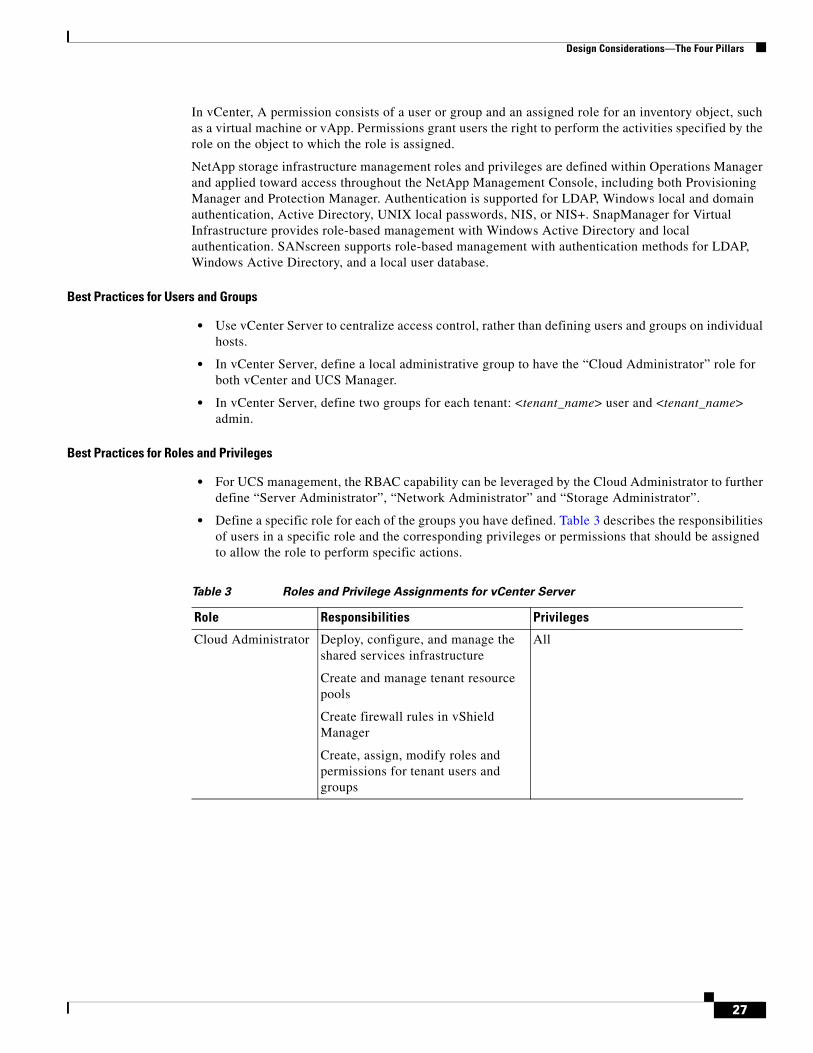
• Define a specific role for each of the groups you have defined. Table 3 describes the responsibilities of users in a specific role and the corresponding privileges or permissions that should be assigned to allow the role to perform specific actions.
Table 3 Roles and Privilege Assignments for vCenter Server
Role Responsibilities Privileges
Cloud Administrator Deploy, configure, and manage the shared services infrastructure
Create and manage tenant resource pools
Create firewall rules in vShield Manager
Create, assign, modify roles and permissions for tenant users and groups
All
27

Design Considerations—The Four Pillars
Permission Assignment for vSphere Objects
Role-based access control capabilities built in with vCenter prevents tenants from accessing each other’s managed resources. For example, tenant A is not able to view virtual machines/vApp owned by tenant B. Making permission assignments in vCenter Server to vSphere Objects lets you customize the specific permissions within the multi-tenant environment.
Tenant Administrator
Deploy virtual machines or vApps in the dedicated resource pool
Assign virtual machines or vApps to networks
Modify compute (CPU/memory) resource allocation for virtual machines or vApps
Virtual Machine.Inventory.Create
Virtual Machine.Configuration.Add New Disk (if creating a new virtual disk)
Virtual Machine.Configuration.Add Existing Disk (if using an existing virtual disk)
Virtual Machine.Configuration.Raw Device (if using a RDM or SCSI pass-through device)
Resource.Assign Virtual Machine to Resource Pool
Datastore.Allocate Space
Network.Assign Network
Tenant User Install guest operating system on virtual machines
Configure floppy, CD/DVD media for virtual machines
Power on, off, reset, or suspend virtual machines
Remote console access
Virtual Machine.Interaction.Answer Question
Virtual Machine.Interaction.Console Interaction
Virtual Machine.Interaction.Device Connection
Virtual Machine.Interaction.Power Off
Virtual Machine.Interaction.Power On
Virtual Machine.Interaction.Reset
Virtual Machine.Interaction.Configure CD Media (if installing from a CD)
Virtual Machine.Interaction.Configure Floppy Media (if installing from a floppy disk)
Virtual Machine.Interaction.Tools Install
Table 3 Roles and Privilege Assignments for vCenter Server
28
Design Considerations—The Four Pillars
Best Practices for Object Permission Assignments
• At the data center level, add the group containing cloud administrator users and assign the group the “Cloud Administrator” role. This grants cloud administrator access to all of the objects managed by vCenter Server (Clusters, ESX hosts, resource pools, datastores, virtual machines, virtual switches, etc.).
• At the individual tenant resource pool level, add the specific tenant group containing tenant administrators and assign the group the “Tenant Administrator” role. This grants tenant administrators the ability to provision new virtual machines and vApps within their own dedicated resource pool.
• At the individual virtual machine or vApp level, add the specific tenant group containing tenant users and assign the group the “Tenant User” role. This grants tenant users the ability to access the remote console of the virtual machine and perform any necessary power operations.
The permission assignments above are designed with simplicity and security in mind, meaning the absolute minimum level of privilege is granted to individual tenant users and administrators. vCenter does offer the flexibility to add/remove any specific privilege, for any specific managed object or task, should the need arise in your environment. To follow best practice security guidelines, such a modification should be reviewed and performed by the Cloud Administrator.
Access Control List (ACL)
ACL is traditionally used to protect or block the undesired access into the network. The ACL can also be used in separating application and entities based on the functional requirements. Such use cases of ACL for achieving separation can have many limitations, such as:
• Performance and scalability—Capability to drop packets in hardware
• Operational complexity—Managing and identifying application, shared entity’s identity, etc.
For reasons motioned above, ACL is used as hard boundary between shared entities and applicable at the Network Layer 2/Layer 3 boundary at the aggregation layer. A virtual firewall such as vShield can facilitate ease of management, configuration, and auditing of access policies that traditionally was implemented with ACLs.
Design Considerations for VM Security
Port-Profile capability in Nexus 1000V is the primary mechanism by which network policy is defined and applied to virtual machines. A port-profile can be used to define configuration options as well as security and service level characteristics. Virtual-Service-Domain (VSD), on the other hand, is a feature within the Nexus 1000V that allows for grouping of one or more port-profiles into one logical domain. The VSD capability allows for services that work in conjunction with Nexus 1000V, such as a virtual firewall entity like vShield, to be integrated into the virtual environment and accessed by the individual domains. This seamless service integration in conjunction with the Nexus 1000V can be used to provide more granular security policies within a virtual environment.
As mentioned above, any set of port-profiles can be functionally separated using a Virtual-Service-Domain. This VSD can then be used to direct traffic to any service or entity within the environment. In the following design, the VSD is used to move a group of virtual machines behind the vShield which is the virtual firewall entity within VSphere. The VSD feature set allows insertion of the vShield virtual appliance in the forwarding path between protected guest virtual machines and the physical network outside of the ESX host. To accomplish this, two areas of configuration are required:
• The port-profiles that identify outside and inside virtual ports of the vShield appliances
• The port-profiles which home guest virtual machines which require firewall protection
29
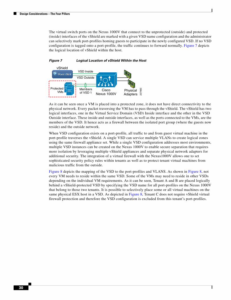
Design Considerations—The Four Pillars
The virtual switch ports on the Nexus 1000V that connect to the unprotected (outside) and protected (inside) interfaces of the vShield are marked with a given VSD name configuration and the administrator can selectively mark port-profiles homing guests to participate in the newly configured VSD. If no VSD configuration is tagged onto a port-profile, the traffic continues to forward normally. Figure 7 depicts the logical location of vShield within the host.
Figure 7 Logical Location of vShield Within the Host
As it can be seen once a VM is placed into a protected zone, it does not have direct connectivity to the physical network. Every packet traversing the VM has to pass through the vShield. The vShield has two logical interfaces, one in the Virtual Service Domain (VSD) Inside interface and the other in the VSD Outside interface. These inside and outside interfaces, as well as the ports connected to the VMs, are the members of the VSD. It hence acts as a firewall between the isolated port group (where the guests now reside) and the outside network.
When VSD configuration exists on a port-profile, all traffic to and from guest virtual machine in the port-profile traverses the vShield. A single VSD can service multiple VLANs to create logical zones using the same firewall appliance set. While a single VSD configuration addresses most environments, multiple VSD instances can be created on the Nexus 1000V to enable secure separation that requires more isolation by leveraging multiple vShield appliances and separate physical network adapters for additional security. The integration of a virtual firewall with the Nexus1000V allows one to set sophisticated security policy rules within tenants as well as to protect tenant virtual machines from malicious traffic from the outside.
Figure 8 depicts the mapping of the VSD to the port-profiles and VLANS. As shown in Figure 8, not every VM needs to reside within the same VSD. Some of the VMs may need to reside in other VSDs depending on the individual VM requirements. As it can be seen, Tenant A and B are placed logically behind a vShield-protected VSD by specifying the VSD name for all port-profiles on the Nexus 1000V that belong to those two tenants. It is possible to selectively place some or all virtual machines on the same physical ESX host in a VSD. As depicted in Figure 8, Tenant C does not require vShield virtual firewall protection and therefore the VSD configuration is excluded from this tenant’s port-profiles.
CiscoNexus 1000V
PhysicalAdapters
VSD Inside
VSD Outside
Membersof VSD 1
ProtectedVMs
2279
83
vShield
30
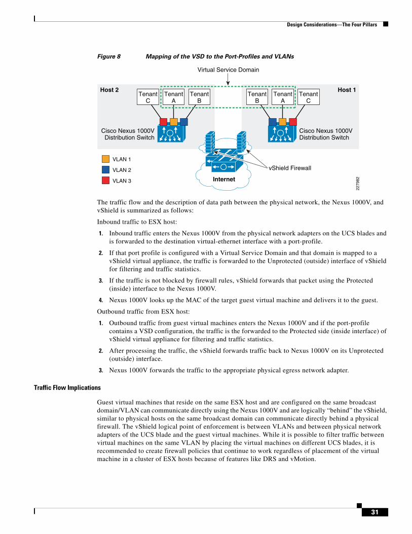
Design Considerations—The Four Pillars
Figure 8 Mapping of the VSD to the Port-Profiles and VLANs
The traffic flow and the description of data path between the physical network, the Nexus 1000V, and vShield is summarized as follows:
Inbound traffic to ESX host:
1. Inbound traffic enters the Nexus 1000V from the physical network adapters on the UCS blades and is forwarded to the destination virtual-ethernet interface with a port-profile.
2. If that port profile is configured with a Virtual Service Domain and that domain is mapped to a vShield virtual appliance, the traffic is forwarded to the Unprotected (outside) interface of vShield for filtering and traffic statistics.
3. If the traffic is not blocked by firewall rules, vShield forwards that packet using the Protected (inside) interface to the Nexus 1000V.
4. Nexus 1000V looks up the MAC of the target guest virtual machine and delivers it to the guest.
Outbound traffic from ESX host:
1. Outbound traffic from guest virtual machines enters the Nexus 1000V and if the port-profile contains a VSD configuration, the traffic is the forwarded to the Protected side (inside interface) of vShield virtual appliance for filtering and traffic statistics.
2. After processing the traffic, the vShield forwards traffic back to Nexus 1000V on its Unprotected (outside) interface.
3. Nexus 1000V forwards the traffic to the appropriate physical egress network adapter.
Traffic Flow Implications
Guest virtual machines that reside on the same ESX host and are configured on the same broadcast domain/VLAN can communicate directly using the Nexus 1000V and are logically “behind” the vShield, similar to physical hosts on the same broadcast domain can communicate directly behind a physical firewall. The vShield logical point of enforcement is between VLANs and between physical network adapters of the UCS blade and the guest virtual machines. While it is possible to filter traffic between virtual machines on the same VLAN by placing the virtual machines on different UCS blades, it is recommended to create firewall policies that continue to work regardless of placement of the virtual machine in a cluster of ESX hosts because of features like DRS and vMotion.
Host 1
Cisco Nexus 1000VDistribution Switch
vShield Firewall
Virtual Service Domain
VLAN 1
VLAN 2
VLAN 3
TenantC
TenantA
TenantB
Host 2
Internet
Cisco Nexus 1000VDistribution Switch
TenantC
TenantA
TenantB
2279
82
31
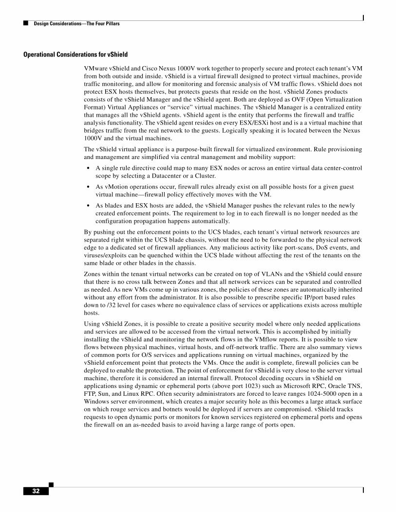
Design Considerations—The Four Pillars
Operational Considerations for vShield
VMware vShield and Cisco Nexus 1000V work together to properly secure and protect each tenant’s VM from both outside and inside. vShield is a virtual firewall designed to protect virtual machines, provide traffic monitoring, and allow for monitoring and forensic analysis of VM traffic flows. vShield does not protect ESX hosts themselves, but protects guests that reside on the host. vShield Zones products consists of the vShield Manager and the vShield agent. Both are deployed as OVF (Open Virtualization Format) Virtual Appliances or “service” virtual machines. The vShield Manager is a centralized entity that manages all the vShield agents. vShield agent is the entity that performs the firewall and traffic analysis functionality. The vShield agent resides on every ESX/ESXi host and is a a virtual machine that bridges traffic from the real network to the guests. Logically speaking it is located between the Nexus 1000V and the virtual machines.
The vShield virtual appliance is a purpose-built firewall for virtualized environment. Rule provisioning and management are simplified via central management and mobility support:
• A single rule directive could map to many ESX nodes or across an entire virtual data center-control scope by selecting a Datacenter or a Cluster.
• As vMotion operations occur, firewall rules already exist on all possible hosts for a given guest virtual machine—firewall policy effectively moves with the VM.
• As blades and ESX hosts are added, the vShield Manager pushes the relevant rules to the newly created enforcement points. The requirement to log in to each firewall is no longer needed as the configuration propagation happens automatically.
By pushing out the enforcement points to the UCS blades, each tenant’s virtual network resources are separated right within the UCS blade chassis, without the need to be forwarded to the physical network edge to a dedicated set of firewall appliances. Any malicious activity like port-scans, DoS events, and viruses/exploits can be quenched within the UCS blade without affecting the rest of the tenants on the same blade or other blades in the chassis.
Zones within the tenant virtual networks can be created on top of VLANs and the vShield could ensure that there is no cross talk between Zones and that all network services can be separated and controlled as needed. As new VMs come up in various zones, the policies of these zones are automatically inherited without any effort from the administrator. It is also possible to prescribe specific IP/port based rules down to /32 level for cases where no equivalence class of services or applications exists across multiple hosts.
Using vShield Zones, it is possible to create a positive security model where only needed applications and services are allowed to be accessed from the virtual network. This is accomplished by initially installing the vShield and monitoring the network flows in the VMflow reports. It is possible to view flows between physical machines, virtual hosts, and off-network traffic. There are also summary views of common ports for O/S services and applications running on virtual machines, organized by the vShield enforcement point that protects the VMs. Once the audit is complete, firewall policies can be deployed to enable the protection. The point of enforcement for vShield is very close to the server virtual machine, therefore it is considered an internal firewall. Protocol decoding occurs in vShield on applications using dynamic or ephemeral ports (above port 1023) such as Microsoft RPC, Oracle TNS, FTP, Sun, and Linux RPC. Often security administrators are forced to leave ranges 1024-5000 open in a Windows server environment, which creates a major security hole as this becomes a large attack surface on which rouge services and botnets would be deployed if servers are compromised. vShield tracks requests to open dynamic ports or monitors for known services registered on ephemeral ports and opens the firewall on an as-needed basis to avoid having a large range of ports open.
32

Design Considerations—The Four Pillars
vShield and Nexus 1000V Design
The vShield Manager and the vShield virtual appliance management interfaces can be placed on the same VLAN as the vCenter server.
The vShield virtual appliance uses three virtual network interface, one for management to connect to the vShield manager. The other two are used to connect to the original Nexus 1000V for unprotected traffic and the protected VM respectively. The protected and unprotected interfaces need to be configured on the Nexus 1000V which enables the vShield agent to use those defined interfaces as vNICs. It is recommended that the management network be implemented in an Out-of-Band (OOB) network where a firewall may be used to restrict traffic to that network. If the vShield manager is residing in the OOB network, then it is required that the OOB network allow traffic flow for the following flows:
• Port 22—Secure Shell or SSH (TCP)—Used for communication between vShield manager and agents.
• Port 123—Network Time Protocol (UDP)—Used for synchronization of the vShield manager and agents.
• Port 443—HTTP Secure (TCP)—Used for PCs to access to the user interface of the vShield manager.
• Port 162—SNMP-Trap (UDP)—Used for SNMP trap data between vShield agents and vShield manager.
vShield provides firewalling capability and networking analysis as long as traffic flows through it. There are various traffic flow scenarios that can determine whether traffic flows through the vShield:
• Virtual Machines residing on the same VLAN—In this case vShield can provide protection against traffic coming from the outside or from a different broadcast domain. In this scenario, it does not protect traffic from VMs that reside on the same VLAN, unless the VMs reside on different hosts.
• Virtual Machines residing on different VLANs— vShield provides protection from outside unprotected network as well as traffic between each of the VMs that reside on different VLANs.
Since the vShield inherits all VM inventory information from the vCenter, it is possible to leverage vCenter container names such as Datacenters, Clusters, Portgroups, and VLANs to simplify creation and maintenance of firewall rules by referencing these objects in source and destination fields of the firewall rules. It is ideal to keep this feature in mind during installation and placement of the virtual machines to reduce the sprawl of firewall rules and to make the security policy be agnostic to changes of the IP addressing on the network. Also, a rule hierarchy exists in the vShield firewall configuration which allows one to control the scope of where the rules should be enforced (across all ESX hosts in the Datacenter, across a specific Cluster, etc.).
An important factor to consider for vShield deployments is placement of the vShield agent. If all virtual machines in the environment require protection at the ESX level, then the vShield would be deployed to all ESX hosts. To support mobility, firewall rules and protocol state for TCP, UDP, and ICMP are transferred between ESX hosts in the same Cluster as VMs migrate using vMotion.
There maybe situations where one does not need to protect virtual machines at the host. In cases where one needs extremely high throughput or for extremely time-sensitive applications, one can use ACLs at the core aggregation points or use physical firewalls within the network to protect the virtual machines. In this case one can simply remove the corresponding virtual machines from the VSD and use the port-profile functionality within the Nexus 1000V to manage and forward traffic.
Deployment Scenarios for vShield
Typical deployment scenarios where vShield can provide protection are summarized below.
33
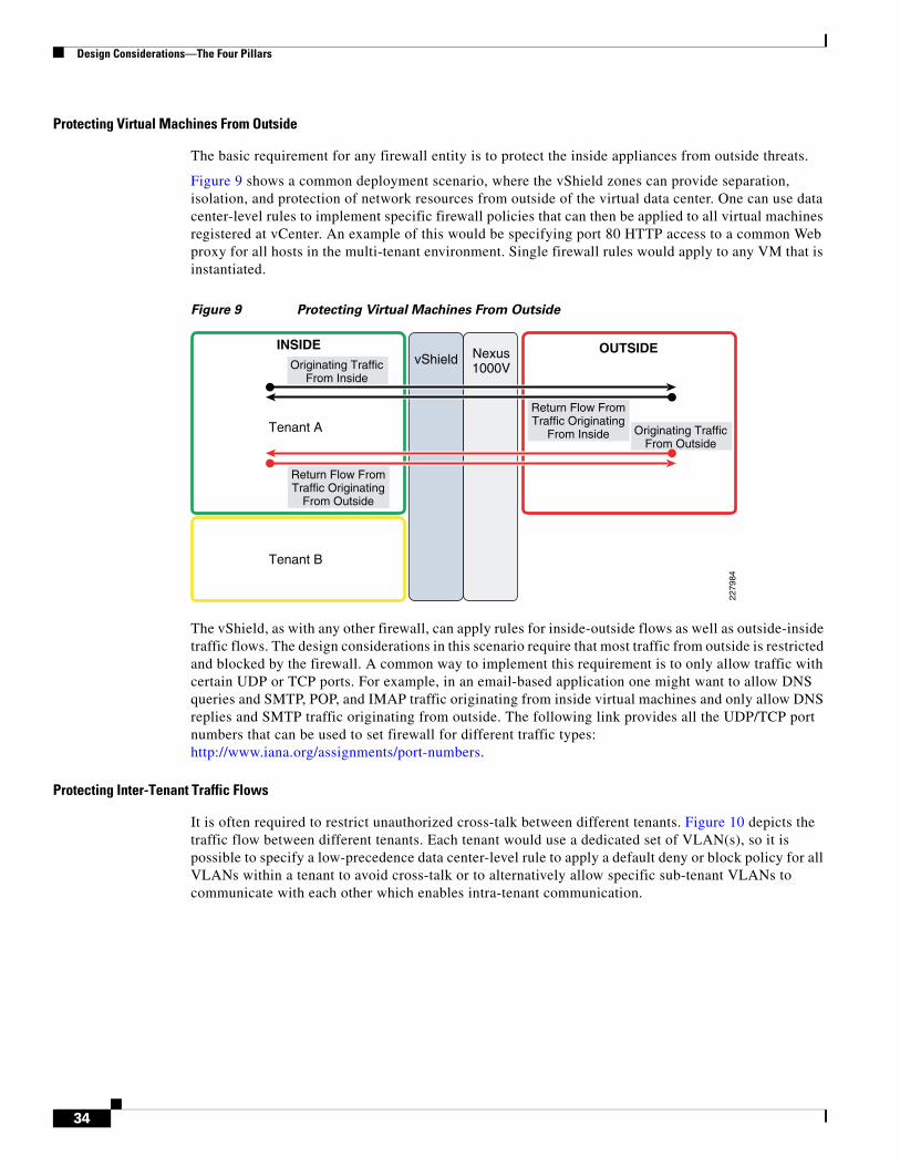
Design Considerations—The Four Pillars
Protecting Virtual Machines From Outside
The basic requirement for any firewall entity is to protect the inside appliances from outside threats.
Figure 9 shows a common deployment scenario, where the vShield zones can provide separation, isolation, and protection of network resources from outside of the virtual data center. One can use data center-level rules to implement specific firewall policies that can then be applied to all virtual machines registered at vCenter. An example of this would be specifying port 80 HTTP access to a common Web proxy for all hosts in the multi-tenant environment. Single firewall rules would apply to any VM that is instantiated.
Figure 9 Protecting Virtual Machines From Outside
The vShield, as with any other firewall, can apply rules for inside-outside flows as well as outside-inside traffic flows. The design considerations in this scenario require that most traffic from outside is restricted and blocked by the firewall. A common way to implement this requirement is to only allow traffic with certain UDP or TCP ports. For example, in an email-based application one might want to allow DNS queries and SMTP, POP, and IMAP traffic originating from inside virtual machines and only allow DNS replies and SMTP traffic originating from outside. The following link provides all the UDP/TCP port numbers that can be used to set firewall for different traffic types: http://www.iana.org/assignments/port-numbers.
Protecting Inter-Tenant Traffic Flows
It is often required to restrict unauthorized cross-talk between different tenants. Figure 10 depicts the traffic flow between different tenants. Each tenant would use a dedicated set of VLAN(s), so it is possible to specify a low-precedence data center-level rule to apply a default deny or block policy for all VLANs within a tenant to avoid cross-talk or to alternatively allow specific sub-tenant VLANs to communicate with each other which enables intra-tenant communication.
vShield Nexus1000VOriginating Traffic
From Inside
Originating TrafficFrom Outside
Return Flow FromTraffic Originating
From Outside
Return Flow FromTraffic Originating
From Inside
INSIDE OUTSIDE
2279
84
Tenant B
Tenant A
34

Design Considerations—The Four Pillars
Figure 10 Protecting Inter-Tenant Traffic Flows
Implementing Sub-Tenant Security Rules
For many data center applications, a three-tier application architecture is implemented where the application components reside on different hosts and are separated via firewalls. It is a common practice to separate the database cluster from the application and Web-server tier to ensure the highest level of security. Firewall rules are needed to prevent the client accessing the Web server to have direct access to the database cluster. This would prevent SQL injection, cross scripting, and other application-based attacks. To implement these security requirements, each tier must be implemented on a separate VLAN. This would allow one to set firewall rules within vShield to protect sub-tenant entities from other applications within the same tenant. A typical three-tier scenario is depicted in Figure 11.
Figure 11 Implementing Sub-Tenant Security Roles
In Figure 11, the database cluster is protected from the front-end Web portal, while simultaneously allowing communication between the front-end Web server and the application server.
vShield
Originating TrafficFrom Tenant A
Originating TrafficFrom Tenant A
Return ForTraffic Originating
From Tenant A
Return ForTraffic Originating
From Tenant A
INSIDE OUTSIDE
2279
85
Tenant B
Tenant A
Nexus1000V
INSIDE OUTSIDE
2279
86
Tenant A
Sub-Tenant 1Web-PortalFront End
Sub-Tenant 2Application Server
Business Logic
Sub-Tenant 3Database
Cluster
vShield Nexus1000V
Originating TrafficFrom Sub-Tenant
Originating TrafficFrom Outside
Originating TrafficFrom Outside
35
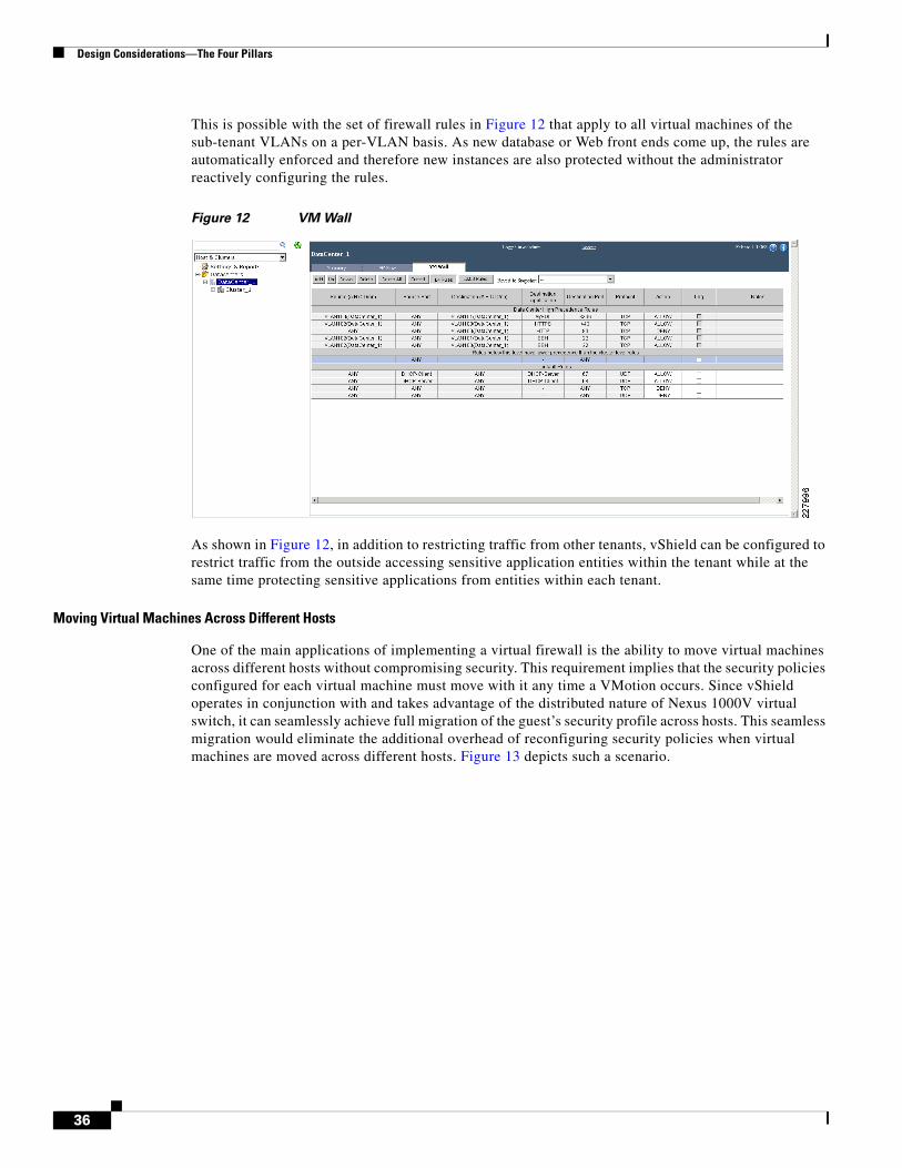
Design Considerations—The Four Pillars
This is possible with the set of firewall rules in Figure 12 that apply to all virtual machines of the sub-tenant VLANs on a per-VLAN basis. As new database or Web front ends come up, the rules are automatically enforced and therefore new instances are also protected without the administrator reactively configuring the rules.
Figure 12 VM Wall
As shown in Figure 12, in addition to restricting traffic from other tenants, vShield can be configured to restrict traffic from the outside accessing sensitive application entities within the tenant while at the same time protecting sensitive applications from entities within each tenant.
Moving Virtual Machines Across Different Hosts
One of the main applications of implementing a virtual firewall is the ability to move virtual machines across different hosts without compromising security. This requirement implies that the security policies configured for each virtual machine must move with it any time a VMotion occurs. Since vShield operates in conjunction with and takes advantage of the distributed nature of Nexus 1000V virtual switch, it can seamlessly achieve full migration of the guest’s security profile across hosts. This seamless migration would eliminate the additional overhead of reconfiguring security policies when virtual machines are moved across different hosts. Figure 13 depicts such a scenario.
36

Design Considerations—The Four Pillars
Figure 13 Moving Virtual Machines Across Different Hosts
Design Considerations for Compute Resource Separation
In a multi-tenant shared services infrastructure, all compute resources are aggregated into a single large cluster. The Cloud Administrator can then compartmentalize all resources in the cluster by creating multiple resource pools as direct children of the cluster and dedicate them to infrastructure services and tenant services.
Resource Separation in VMware
To share resources, the Cloud Administrator can make a pool of resources available to infrastructure and tenant services by leveraging the design model below. For isolation between resource pools, the allocation changes that are internal to one resource pool do not unfairly affect other unrelated resource pools:
• Create a single cluster to aggregate the compute resources from all the UCS blade servers.
• Create two resource pools, one for infrastructure services and the other for tenant services.
Infrastructure services are virtual machines that are required to configure and manage the vSphere platform. The following are the primary infrastructure services virtual machines and their respective roles:
• vCenter Server—For overall management of vSphere platform
• Microsoft SQL Server—Dedicated database server for vCenter
• vShield Manager—For management of vShield policy creation, management, and forensics
• vShield agent—Traffic bridge between unprotected and protected networks in each ESX Server host
• Cisco Nexus 1000V VSM—For management of the VEM instance in each ESX Server host
Tenant services are resources dedicated for all tenants. The Cloud Administrator can create a child tenant resource pool for an individual tenant and delegate the allocation of the individual tenant resources to the Tenant Administrator.
Access control and delegation—When a Cloud Administrator makes a resource pool available to a tenant, the Tenant Administrator can then perform all virtual machine and/or vApp creation and management within the boundaries of the resource to which the resource pool is entitled by the current
INSIDE OUTSIDE
2279
87
UCS Chassis
Host 1
Host 2
Host 3
vShield Nexus1000V
Security Policy Consistentafter vMotion
VM-Tenant A
vMotion of VM
VM-Tenant A
VM-Tenant B
VM-Tenant A
VM-Tenant B
VM-Tenant C
VM-Tenant B
VM-Tenant C
37
Design Considerations—The Four Pillars
shares, reservation, and limit settings. Recommended settings are discussed in greater depth in Service Assurance. Delegation of tenant resource pool management can leverage the RBAC model defined previously.
Figure 14 Resource Pools
Secure Separation in UCS
There are two basic approaches to achieving compute separation, at the blade level or higher up within the VM guest layer. The Secure Multi-Tenant project focused on using the abilities of VMware and the Nexus 1000v software switch to achieve “compute separation” among the various guest instances. There are some customers who may choose to instrument separation at the physical blade level using what UCS exposes; this is described briefly below.
The main elements of this capability are RBAC (discussed earlier), organizations, pools of resources, and policies. The UCS hardware and policies can be assigned to different organizations such that the desired customer or line of business has access to the right compute blade for a given workload. The rich set of policies in UCS can be applied per organization to ensure the right sets of attributes and I/O policies are assigned to the correct organization. Each organization can have their own pools of resources including servers, MAC Ids, WWPNs, WWNNs, and UUIDs to enable statelessness within an organization or across them.
Design Considerations for Network Separation
Secured separation is one of the basic requirements for the multi-tenant environment as each user/department requires some level of isolation from each other. The separation requirement can vary significantly based on the network layer boundary and generally falls into two domains:
• Network Layer 3 (Aggregation/Core) Separation
• Network Layer 2 (Access) Separation
Tenant A Resource Pool Tenant B Resource Pool
“Parent” Resource Pool
2279
88
38
Design Considerations—The Four Pillars
Network Layer 3 (Aggregation/Core) Separation
Laye 3 separation enables virtualized data and control plane path for end-to-end Layer 3 network connectivity. Examples of techniques used for Layer 3 virtualization include Virtual Route Forwarder (VRF), MPLS, etc. This design methodology is commonly referred as network virtualization. The validated design scope and implementation details for network virtualization are available at: http://www.cisco.com/en/US/solutions/ns340/ns414/ns742/ns815/landing_cNet_virtualization.html.
Network Layer 2 (Access) Separation
Secure separation at Layer 2 is an essential requirement of multi-tenant network design. The separation is critical since it defines the operational manageability and access. It also enables a control point for governing and tools to address the degree of separation. Naturally, the shared resource requires separation for a variety of reasons:
• Compliance and regulatory requirements
• Degree of confidentiality
• Performance
• Span of control and accountability
• Traditional view of building infrastructure
Methods to Achieve Layer 2 Separation
The following tools are used to achieve secure separation. Design considerations and applicability to multi-tenant design are discussed in detail in the following section:
• Separate physical infrastructure—Though costly and complex to manage, yet needed to meet absolute requirement of compliance and regulatory laws
• Traditional network layer firewall—To meet the degree of confidentiality
• VLANs for network and administrative level separation
• vShield to control VM level access control and separation
• ACL to identify application and classification within or among several tenants
• Nexus 1000V port-profile enabling separation criteria at the VM level for the shared entities
• QoS classification to enable service levels among shared entities
In addition central administrative authority can further employ policy methods to separate management, control, and data functions need for each tenant:
• Each tenant requires separate administrative domain for application and user access management.
• The network management and monitoring (out of band network)
Layer 2 Separation Design Considerations
To properly secure and separate each tenant at the network access layer, network architects and engineers can employ various methods and functionalities. Each method varies in the degree of control it offers and the methods can overlap. This design guide enables the following design choices in applying each method of separation.
The firewall represents a hard boundary separation and is not covered in this design guide.
39
Design Considerations—The Four Pillars
VLANs are one of the basic building blocks used in this design guide to achieve Layer 2 separation. Proper VLAN design is essential in successfully deploying secure multi-tenancy domain. The type of VLANs used and their functional mapping to separate compute, network, and storage resources is covered in detail in VLAN Design Considerations.
Access Control List (ACL) is also part of the network secure separation and is discussed in Access Control List (ACL).
The Port-Profile capability of Nexus 1000V enables the separation of VMs at the port level. It is a flexible way one can associate VMs and provide further capability to define security and services level characteristics to the VM traffic.
QoS-based separation is essential to provide differentiated access to the network resources based on application response time need and categorization of various types of network traffic at the tenant level.
VLAN Design Considerations
VLANs are the primary means of separation in multi-tenant design. VLAN design also requires planning and awareness of the administrative roles of compute, application, storage, and network resources. One of the challenges of a multi-tenant environment is to accommodate varied types and functional uses of VLANs with appropriate security while providing operational stability and control. Each major resources space (compute, storage, and network) requires the various control and manageability of the devices within its scope. Typical functional uses of VLANs in traditional design are covered below for reference and are a basis for further design considerations on how to consolidate and classify each function based on its criticality in multi-tenant design.
Note The term “control plane” is used as a broad category of services or communication requirements that enables multi-tenant services. In general any data not directly related to users is defined as control plane. Network literature and devices describe “control” for both internal communications within devices as well as protocol interaction between devices (CDP, LACP etc.). The “network control plane” refers to a protocol communication between networked devices.
Compute Space
The compute space consists of UCS and VMware components—ESX Hosts and vSphere. In a traditional design, the following functions are configured as separate VLANs:
1. UCS out-of-band management interface to redundant fabric interconnect and UCS loopback KVM access to each blade severs.
2. ESX service console access interface—A service console port, which is set up by default during installation, is required for vCenter management of ESX server host and heartbeat communication between ESX Servers in a VMware HA cluster.
3. VMkernel port—The VMkernel TCP/IP stack provides services for NFS, iSCSI storage connectivity, and vMotion. The VMkenel interface connects VMkernel services (NFS, iSCSI, or vMotion) to the physical network. Multiple VMkernal interface can be defined to provide various degree of control.
4. vShpere heartbeat for active and standby vCenter VMs.
5. Separate VLANs for tenant VM(s) and application management.
Storage Space
1. Separate VLANs for each tenant storage domain (vFiler unit).
40
Design Considerations—The Four Pillars
2. Management VLANs for HTTP and console access to NetApp controller.
Network Space
1. Management VRF VLANs for Nexus 7000 and 5000.
2. Nexus 1000V network management interface—To manage the IP-based connectivity to Nexus 1000V. Although the management interface is not used to exchange data between the VSM and VEM, it is used to establish and maintain the connection between the VSM and VMware vCenter Server.
3. Nexus 1000V control interface—The control interface is a Layer 2 interface used by VSM to communicate with the VEMs. This interface handles low-level control packets such as heartbeats as well as any configuration data that needs to be exchanged between the VSM and VEM. Because of the nature of the traffic carried over the control interface, it is the most important interface in the Cisco Nexus 1000V Series switch.
4. Nexus 1000V packet—The packet interface is a Layer 2 interface that is used to carry network packets that need to be coordinated across the entire Cisco Nexus 1000V Series Switch. This interface is used by network control traffic such as Cisco Discovery Protocol and Internet Group Management Protocol (IGMP) control packets.
VLAN Planning and Design Scope
VLAN design enables cloud administrators to provide differentiated services by separating the critical operational requirements of managing cloud components. In addition to properly secure the VLANs, it is important to map administrative scope and the access requirements to each category of VLANs. Therefore the roles and purpose of VLANs are grouped into two major types.
• Infrastructure VLANs Group—This category of VLANs belongs to all the necessary functionality of multi-tenant environment services for compute, storage, and network.
– Management VLANs
These VLANs are used for managing VMware ESX hosts, NetApp storage controller, and networking devices such as Nexus 1000V, Nexus 5000, and Nexus 7000. This category also includes VLANs for monitoring, SNMP management, and network level monitoring (RSPAN).
– Control VLANs
These VLANs are used for connectivity across compute, network, and storage entities. For example, these VLANs include VMkernel interface for NFS data store as well as for vMotion and Nexus 1000V control and packet interface connectivity.
• Tenant VLANs Group—This group consists of VLANs that provide all the functionality of tenant-related data.
– Application Admin VLANs
This design guide assumes one administrative zone for the central point of control. However, management of each tenant VM and application administration requires secured separation to maintain distinct tenant identity and role. Thus each tenant requires separate dedicated VLANs for VM and application administration.
– Data VLANs
The data VLANs consist of any VLANs used in servicing the customer application. Typically this includes front-end VLANs for application and back-end VLANs for application access to databases or storage fabric. Additionally each tenant requires VLANs for traffic monitoring and backup VLANs for data management.
41
Design Considerations—The Four Pillars
VLAN Consolidation
In a multi-tenant environment, VLAN sprawl is expected based on growing numbers of tenants, VMs, and applications. In addition, if traditional practice is followed, each of the functions described above would create numerous VLAN instances. The VLAN sprawl becomes a real challenge in a secured multi-tenant environment which leads to:
• Higher administrative cost—Inefficient resource usage and administrative burdens of configuring separate VLAN for each functional use.
• Security non-compliance—Each VLAN requires separate control and access control point where the chances of non-compliance with respect to security are increased due to misconfiguration.
On the other hand, the advantagea of consolidation of VLANs are:
Reducing the number of VLANs enables operational consistency and manageability. If consolidated, each of the VLAN categories or types can be mapped to VLAN-based port-profiles functionality in Cisco Nexus 1000V. This mapping enables streamlined access control and QoS classification. VLAN consolidation also allows the capability of monitoring via a single instance of RSPAN session for end-to-end events for control plane function. The later capability is crucial for virus infection control and troubleshooting infrastructure problems. The consolidation of VLANs among tenants may not be possible because of secure separation requirements. However, the number of VLANs required under an infrastructure VLANs Group (management and control plane) can be consolidated since many VLANs serve similar function. In this design, the management and control VLANs group are merged into three VLANs—one routable and two non-routable VLANs—to represent most of VLANs related to control and management function. The design proposes the following rationale and explanation of consolidated VLANs:
• NOC management functionality requires accessibility of critical resources of compute, network, and storage from remote segments. For this reason, ESX-service consoles, NetApp controller console, Nexus 1000V management VLANs, network devices management, UCS OOB, and KVM are consolidated into single routable VLANs.
• In this design NFS datastore is used for live OS data for both ESX host as well guest VM. This is a critical infrastructure enabler for state-less computing and thus kept on separate VLAN as well as dedicated VMkernel port. This VLAN should be non-routable because it does not require outside resources and this also reduces security exposure. A common datastore for ESE boot and VMs OS is used for the entire multi-tenant environment, further reducing the VLANs needed for each tenant. Security and administrative access to these VLANs is covered with a single administrative authority. All tenants manage their resources through vCenter; ESX host should be transparent as well separate to the end users/tenant administrators.
• Traditionally VLANs requiring Nexus 1000V operation—control and packet interfaces—are kept in separate VLANs due to the critical nature of its operation. This falls into same category as NFS data store in terms degree of protection of control plane stability and is thus consolidated with NFS datastore VLAN.
• vMotion requires IP connectivity within ESX cluster. In this design it is kept in a separate VLAN with dedicated VMkernel port. This VLAN is not required to be routable.
Note It is strongly recommended to have a host (which can function as SNMP relay) with IP connectivity to any non-routed VLAN. Without an IP device it is extremely hard to verify individual resource connectivity and SNMP management, which may necessitate routing capability.
42
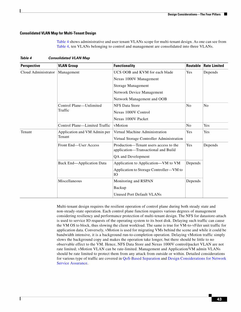
Design Considerations—The Four Pillars
Consolidated VLAN Map for Multi-Tenant Design
Table 4 shows administrative and user tenant VLANs scope for multi-tenant design. As one can see from Table 4, ten VLANs belonging to control and management are consolidated into three VLANs.
Multi-tenant design requires the resilient operation of control plane during both steady state and non-steady-state operation. Each control plane function requires various degrees of management considering resiliency and performance protection of multi-tenant design. The NFS for datastore-attach is used to service IO requests of the operating system to its boot disk. Delaying such traffic can cause the VM OS to block, thus slowing the client workload. The same is true for VM-to-vFiler unit traffic for application data. Conversely, vMotion is used for migrating VMs behind the scene and while it could be bandwidth intensive, it is a background run-to-completion operation. Delaying vMotion traffic simply slows the background copy and makes the operation take longer, but there should be little to no observable effect to the VM. Hence, NFS Data Store and Nexus 1000V control/packet VLAN are not rate limited; vMotion VLAN can be rate-limited. Management and Application/VM admin VLANs should be rate limited to protect them from any attack from outside or within. Detailed considerations for various type of traffic are covered in QoS-Based Separation and Design Considerations for Network Service Assurance.
Table 4 Consolidated VLAN Map
Perspective VLAN Group Functionality Routable Rate Limited
Cloud Administrator Management UCS OOB and KVM for each blade
Nexus 1000V Management
Storage Management
Network Device Management
Network Management and OOB
Yes Depends
Control Plane—Unlimited Traffic
NFS Data Store
Nexus 1000V Control
Nexus 1000V Packet
No No
Control Plane—Limited Traffic vMotion No Yes
Tenant Application and VM Admin per Tenant
Virtual Machine Administration
Virtual Storage Controller Administration
Yes Yes
Front End—User Access Production—Tenant users access to the application—Transactional and Build
QA and Development
Yes Depends
Back End—Application Data Application to Application—VM to VM
Application to Storage Controller—VM to IO
Depends
Miscellaneous Monitoring and RSPAN
Backup
Unused Port Default VLANs
Depends
43
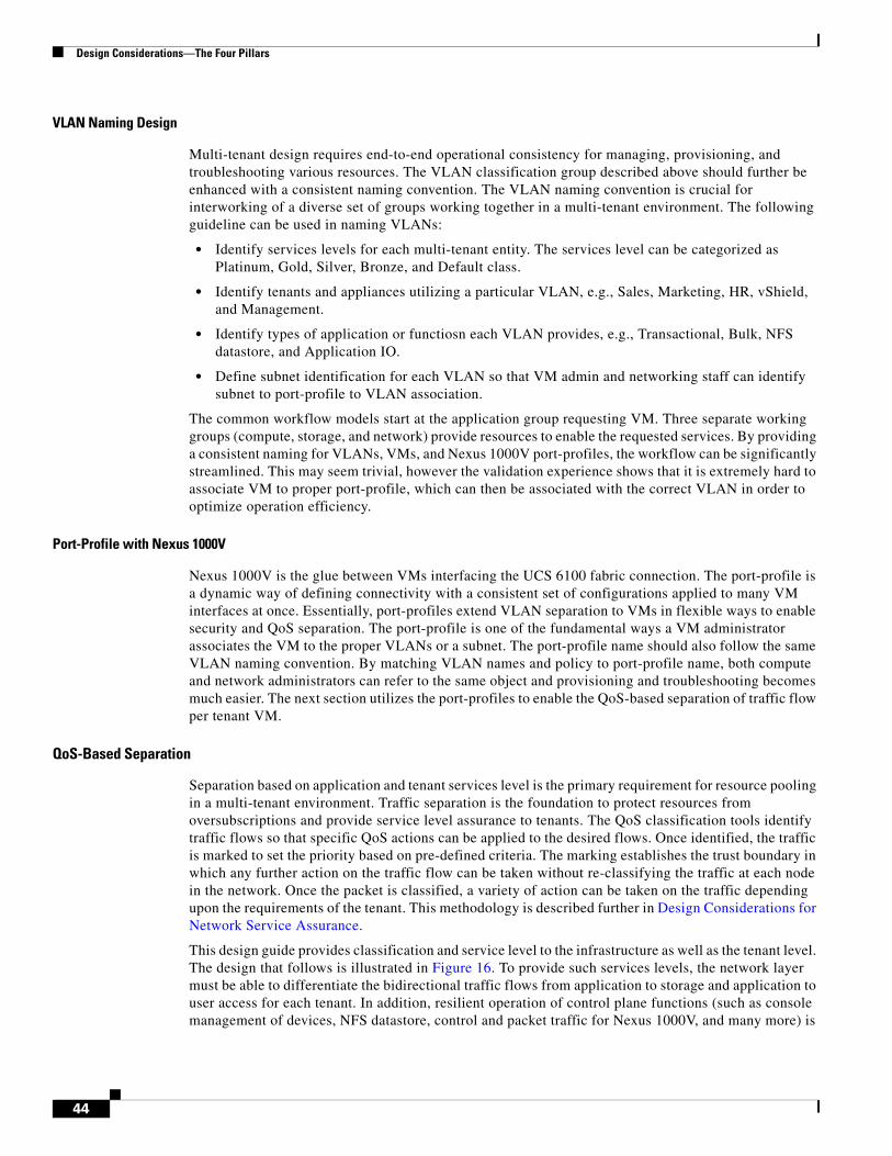
Design Considerations—The Four Pillars
VLAN Naming Design
Multi-tenant design requires end-to-end operational consistency for managing, provisioning, and troubleshooting various resources. The VLAN classification group described above should further be enhanced with a consistent naming convention. The VLAN naming convention is crucial for interworking of a diverse set of groups working together in a multi-tenant environment. The following guideline can be used in naming VLANs:
• Identify services levels for each multi-tenant entity. The services level can be categorized as Platinum, Gold, Silver, Bronze, and Default class.
• Identify tenants and appliances utilizing a particular VLAN, e.g., Sales, Marketing, HR, vShield, and Management.
• Identify types of application or functiosn each VLAN provides, e.g., Transactional, Bulk, NFS datastore, and Application IO.
• Define subnet identification for each VLAN so that VM admin and networking staff can identify subnet to port-profile to VLAN association.
The common workflow models start at the application group requesting VM. Three separate working groups (compute, storage, and network) provide resources to enable the requested services. By providing a consistent naming for VLANs, VMs, and Nexus 1000V port-profiles, the workflow can be significantly streamlined. This may seem trivial, however the validation experience shows that it is extremely hard to associate VM to proper port-profile, which can then be associated with the correct VLAN in order to optimize operation efficiency.
Port-Profile with Nexus 1000V
Nexus 1000V is the glue between VMs interfacing the UCS 6100 fabric connection. The port-profile is a dynamic way of defining connectivity with a consistent set of configurations applied to many VM interfaces at once. Essentially, port-profiles extend VLAN separation to VMs in flexible ways to enable security and QoS separation. The port-profile is one of the fundamental ways a VM administrator associates the VM to the proper VLANs or a subnet. The port-profile name should also follow the same VLAN naming convention. By matching VLAN names and policy to port-profile name, both compute and network administrators can refer to the same object and provisioning and troubleshooting becomes much easier. The next section utilizes the port-profiles to enable the QoS-based separation of traffic flow per tenant VM.
QoS-Based Separation
Separation based on application and tenant services level is the primary requirement for resource pooling in a multi-tenant environment. Traffic separation is the foundation to protect resources from oversubscriptions and provide service level assurance to tenants. The QoS classification tools identify traffic flows so that specific QoS actions can be applied to the desired flows. Once identified, the traffic is marked to set the priority based on pre-defined criteria. The marking establishes the trust boundary in which any further action on the traffic flow can be taken without re-classifying the traffic at each node in the network. Once the packet is classified, a variety of action can be taken on the traffic depending upon the requirements of the tenant. This methodology is described further in Design Considerations for Network Service Assurance.
This design guide provides classification and service level to the infrastructure as well as the tenant level. The design that follows is illustrated in Figure 16. To provide such services levels, the network layer must be able to differentiate the bidirectional traffic flows from application to storage and application to user access for each tenant. In addition, resilient operation of control plane functions (such as console management of devices, NFS datastore, control and packet traffic for Nexus 1000V, and many more) is
44
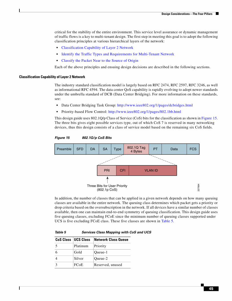
Design Considerations—The Four Pillars
critical for the stability of the entire environment. This service level assurance or dynamic management of traffic flows is a key to multi-tenant design. The first step in meeting this goal is to adopt the following classification principles at various hierarchical layers of the network:
• Classification Capability of Layer 2 Network
• Identify the Traffic Types and Requirements for Multi-Tenant Network
• Classify the Packet Near to the Source of Origin
Each of the above principles and ensuing design decisions are described in the following sections.
Classification Capability of Layer 2 Network
The industry standard classification model is largely based on RFC 2474, RFC 2597, RFC 3246, as well as informational RFC 4594. The data center QoS capability is rapidly evolving to adopt newer standards under the umbrella standard of DCB (Data Center Bridging). For more information on these standards, see:
• Data Center Bridging Task Group: http://www.ieee802.org/1/pages/dcbridges.html
• Priority-based Flow Control: http://www.ieee802.org/1/pages/802.1bb.html
This design guide uses 802.1Q/p Class of Service (CoS) bits for the classification as shown in Figure 15. The three bits gives eight possible services type, out of which CoS 7 is reserved in many networking devices, thus this design consists of a class of service model based on the remaining six CoS fields.
Figure 15 802.1Q/p CoS Bits
In addition, the number of classes that can be applied in a given network depends on how many queuing classes are available in the entire network. The queuing class determines which packet gets a priority or drop criteria based on the oversubscription in the network. If all devices have a similar number of classes available, then one can maintain end-to-end symmetry of queuing classification. This design guide uses five queuing classes, excluding FCoE since the minimum number of queuing classes supported under UCS is five excluding FCoE class. These five classes are shown in Table 5.
PRI VLAN IDCFI
2279
94
Preamble 802.1Q Tag4 Bytes
DASFD SA Type FCSData
Three Bits for User Priority(802.1p CoS)
PT
Table 5 Services Class Mapping with CoS and UCS
CoS Class UCS Class Network Class Queue
5 Platinum Priority
6 Gold Queue-1
4 Silver Queue-2
3 FCoE Reserved, unused
45
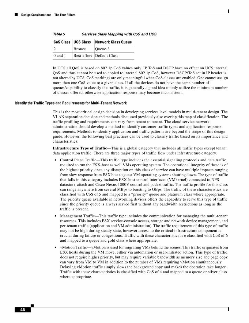
Design Considerations—The Four Pillars
In UCS all QoS is based on 802.1p CoS values only. IP ToS and DSCP have no effect on UCS internal QoS and thus cannot be used to copied to internal 802.1p CoS, however DSCP/ToS set in IP header is not altered by UCS. CoS markings are only meaningful when CoS classes are enabled. One cannot assign more then one CoS value to a given class. If all the devices do not have the same number of queues/capability to classify the traffic, it is generally a good idea to only utilize the minimum number of classes offered, otherwise application response may become inconsistent.
Identify the Traffic Types and Requirements for Multi-Tenant Network
This is the most critical design decision in developing services level models in multi-tenant design. The VLAN separation decision and methods discussed previously also overlap this map of classification. The traffic profiling and requirements can vary from tenant to tenant. The cloud service network administration should develop a method to identify customer traffic types and application response requirements. Methods to identify application and traffic patterns are beyond the scope of this design guide. However, the following best practices can be used to classify traffic based on its importance and characteristics:
Infrastructure Type of Traffic—This is a global category that includes all traffic types except tenant data application traffic. There are three major types of traffic flow under infrastructure category.
• Control Plane Traffic—This traffic type includes the essential signaling protocols and data traffic required to run the ESX-host as well VMs operating system. The operational integrity of these is of the highest priority since any disruption on this class of service can have multiple impacts ranging from slow response from ESX host to guest VM operating systems shutting down. The type of traffic that falls in this category includes ESX-host control interfaces (VMkernel) connected to NFS datastore-attach and Cisco Nexus 1000V control and packet traffic. The traffic profile for this class can range anywhere from several MBps to bursting to GBps. The traffic of these characteristics are classified with CoS of 5 and mapped to a “priority” queue and platinum class where appropriate. The priority queue available in networking devices offers the capability to serve this type of traffic since the priority queue is always served first without any bandwidth restrictions as long as the traffic is present.
• Management Traffic—This traffic type includes the communication for managing the multi-tenant resources. This includes ESX service-console access, storage and network device management, and per-tenant traffic (application and VM administration). The traffic requirement of this type of traffic may not be high during steady state, however access to the critical infrastructure component is crucial during failure or congestions. Traffic with these characteristics is e classified with CoS of 6 and mapped to a queue and gold class where appropriate.
• vMotion Traffic—vMotion is used for migrating VMs behind the scenes. This traffic originates from ESX hosts during the VM move, either via automation or user-initiated action. This type of traffic does not require higher priority, but may require variable bandwidth as memory size and page copy can vary from VM to VM in addition to the number of VMs requiring vMotion simultaneously. Delaying vMotion traffic simply slows the background copy and makes the operation take longer. Traffic with these characteristics is classified with CoS of 4 and mapped to a queue or silver class where appropriate.
2 Bronze Queue-3
0 and 1 Best-effort Default Class
Table 5 Services Class Mapping with CoS and UCS
CoS Class UCS Class Network Class Queue
46

Design Considerations—The Four Pillars
Tenant Data Plane Traffic—This traffic category comprises two major traffic groups. The first one consists of back-end traffic, which includes storage traffic and back-end VM-to-VM traffic for multi-tier applications. The second group consists of user access traffic (generically called front-end application traffic). Each of these traffic groups would require some form of protection based on each tenant application requirements. Each class also requires some form of service differentiation based on enterprise policy. For this reason each of these traffic groups are further divided into three levels of service, Platinum, Gold, and Silver. The mapping of services class to CoS/Queue/UCS-class is show in Table 6. Identifying each user tenant application and user requirement and developing a service model that intersects the various requirement of each tenant is beyond the scope of this design guide. For this reason, in this design guide the services level classification is maintained at the tenant level. In other words, all tenant traffic is treated with a single service level and no further differentiation is provided. However the design methodology is extensible to provide a more granular differentiation model.
• Back-end User Data Traffic—This traffic type includes any traffic that an application requires to communicate within a data center. This can be application to application traffic, application to database, and application to each tenant storage space. The traffic bandwidth and response time requirements vary based on each tenant’s requirements. In this design three levels of services are proposed for back-end user data; each service is classified in separate CoS classes based on the requirements. The services level classification helps differentiating various IO requirements per tenant. Table 6 explains and maps the services class based on IO requirements of the application. Each IO requirement class is mapped to CoS type, queue type, and equivalent UCS bandwidth class.
Note In this design guide, CoS 6 is used for data traffic, which is a departure from traditional QoS framework.
• Front-end User Data Plane Traffic—This class of traffic includes the front-end VM data traffic for each tenant accessed by user. The front-end user traffic can be further sub-divided into three distinct class of traffic. Each of these subclasses have unique requirements in term of bandwidth and response-time. Each traffic subclass is described below with classification rational.
• Transactional and Low-Latency Data—This service class is intended for interactive, time-sensitive data applications which requires immediate response from the application in either direction (example of such could be Web shopping, terminal services, time-based update, etc.). Excessive latency in response times of foreground applications directly impacts user productivity. However not
Table 6 Services Levels for Back-End User Data Traffic
Services Class IO Requirements Cos/Queue/UCS-Class Rational
Platinum Low latency, Bandwidth Guarantee
5/Priority-Q/Platinum class
Real-time IO, no rate limiting, no BW limit, First to serve
Gold Medium latency, No Drop
6/queue-1/Gold class Less than real-time, however traffic is buffered
Silver High latency, Drop/Retransmit
4/queue-2/Silver class Low bandwidth guarantee, Remarking and policing allowed, drop and retransmit handled at the NFS/TCP level
47

Design Considerations—The Four Pillars
all transactional application or users require equal bandwidth and response time requirements. Just like back-end user traffic classification, this subclass offers three levels of services, Platinum, Gold, and Silver and related mappings to CoS/Queue/UCS-Class, as shown in Table 7.
• Bulk Data and High-Throughput Data—This service class is intended for non-interactive data applications. In most cases this type of traffic does not impact user response and thus productivity. However this class may requires high bandwidth for critical business operations. This traffic class may be subject to policing and re-marking. Examples of such traffic include E-mail replication, FTP/SFTP transfers, warehousing application depending on large update on inventory, etc.. This traffic falls into bronze services class with CoS of 2, as shown in Table 8.
• Best Effort—This service class falls into the default class. Any application that is not classified in the services classes already described is assigned a default class. In many enterprise networks, a vast majority of applications default to best effort service class; as such, this default class should be adequately provisioned (a minimum bandwidth recommendation for this class is 25%). Traffic in this class is marked with CoS 0.
• Scavenger and Low-Priority Data—The scavenger class is intended for applications that are not critical to the business. These applications are permitted on enterprise networks, as long as resources are always available for business-critical applications. However, as soon as the network experiences congestion, this class is the first to be penalized and aggressively dropped. Furthermore, the scavenger class can be utilized as part of an effective strategy for DoS (denial of service) and worm attack mitigation. Traditionally in enterprise campus and WAN network this class is assigned a CoS of 1 (DSCP 9).
In this design guide the best effort and scavenger class are merged into one class called “best-effort” in UCS 6100 and “class-default” in Nexus 5000.
Table 7 Services Levels for Transactional User Data Traffic
Services ClassTransactional Requirements Cos/Queue/UCS-Class Rational
Platinum Low latency, Bandwidth Guarantee
5/Priority-Q/Platinum class
Real-time IO, no rate limiting, no BW limit, First to serve
Gold Medium latency, No Drop
6/queue-1/Gold class Less than real-time, however traffic is buffered, policing is allowed
Silver High latency, Drop/Retransmit
4/queue-2/Silver class Low bandwidth guarantee, drop and retransmit permitted, policing or remarking allowed.
Table 8 Services Levels for Bulk User Data Traffic
Services ClassTransactional Requirements Cos/Queue/UCS-Class Rational
Bronze Bulk Application and High Throughput
2/queue-3/Bronze class
48
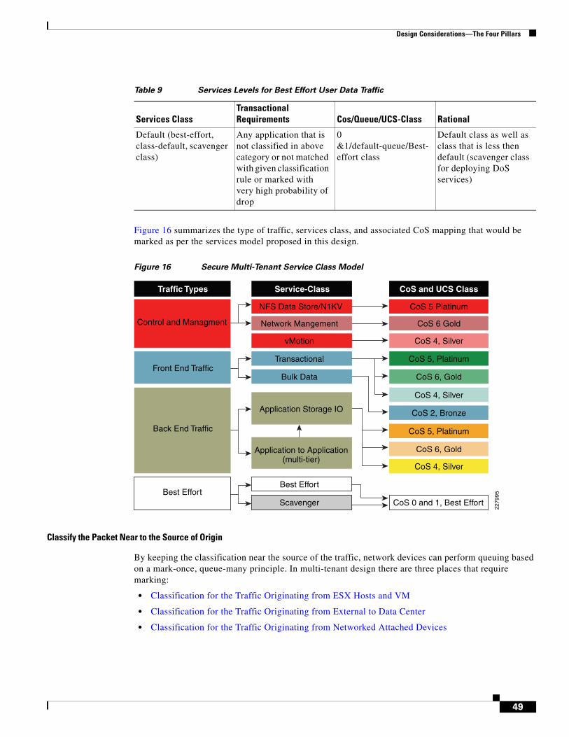
Design Considerations—The Four Pillars
Figure 16 summarizes the type of traffic, services class, and associated CoS mapping that would be marked as per the services model proposed in this design.
Figure 16 Secure Multi-Tenant Service Class Model
Classify the Packet Near to the Source of Origin
By keeping the classification near the source of the traffic, network devices can perform queuing based on a mark-once, queue-many principle. In multi-tenant design there are three places that require marking:
• Classification for the Traffic Originating from ESX Hosts and VM
• Classification for the Traffic Originating from External to Data Center
• Classification for the Traffic Originating from Networked Attached Devices
Table 9 Services Levels for Best Effort User Data Traffic
Services ClassTransactional Requirements Cos/Queue/UCS-Class Rational
Default (best-effort, class-default, scavenger class)
Any application that is not classified in above category or not matched with given classification rule or marked with very high probability of drop
0 &1/default-queue/Best-effort class
Default class as well as class that is less then default (scavenger class for deploying DoS services)
Back End Traffic
Traffic Types
Bulk Data
Application Storage IO
Front End Traffic
vMotion
Application to Application(multi-tier)
Best EffortBest Effort
Scavenger
Service-Class
Control and Managment
CoS 6, Gold
CoS 2, Bronze
CoS 6, Gold
CoS 4, Silver
CoS 4, Silver
CoS and UCS Class
CoS 5, Platinum
CoS 5, Platinum
CoS 4, Silver
CoS 0 and 1, Best Effort
CoS 6 Gold
CoS 5 PlatinumNFS Data Store/N1KV
Network Mangement
Transactional
2279
95
49
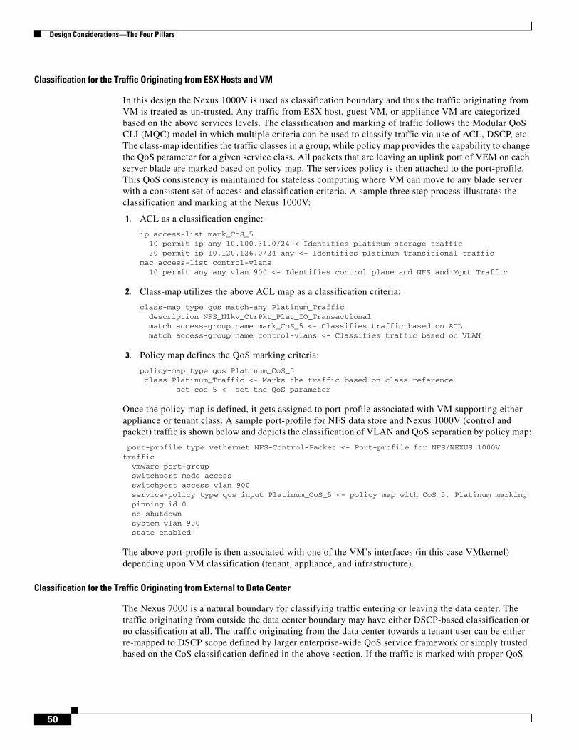
Design Considerations—The Four Pillars
Classification for the Traffic Originating from ESX Hosts and VM
In this design the Nexus 1000V is used as classification boundary and thus the traffic originating from VM is treated as un-trusted. Any traffic from ESX host, guest VM, or appliance VM are categorized based on the above services levels. The classification and marking of traffic follows the Modular QoS CLI (MQC) model in which multiple criteria can be used to classify traffic via use of ACL, DSCP, etc. The class-map identifies the traffic classes in a group, while policy map provides the capability to change the QoS parameter for a given service class. All packets that are leaving an uplink port of VEM on each server blade are marked based on policy map. The services policy is then attached to the port-profile. This QoS consistency is maintained for stateless computing where VM can move to any blade server with a consistent set of access and classification criteria. A sample three step process illustrates the classification and marking at the Nexus 1000V:
1. ACL as a classification engine:
ip access-list mark_CoS_5 10 permit ip any 10.100.31.0/24 <-Identifies platinum storage traffic 20 permit ip 10.120.126.0/24 any <- Identifies platinum Transitional traffic mac access-list control-vlans 10 permit any any vlan 900 <- Identifies control plane and NFS and Mgmt Traffic
2. Class-map utilizes the above ACL map as a classification criteria:
class-map type qos match-any Platinum_Traffic description NFS_N1kv_CtrPkt_Plat_IO_Transactional match access-group name mark_CoS_5 <- Classifies traffic based on ACL match access-group name control-vlans <- Classifies traffic based on VLAN
3. Policy map defines the QoS marking criteria:
policy-map type qos Platinum_CoS_5 class Platinum_Traffic <- Marks the traffic based on class reference set cos 5 <- set the QoS parameter
Once the policy map is defined, it gets assigned to port-profile associated with VM supporting either appliance or tenant class. A sample port-profile for NFS data store and Nexus 1000V (control and packet) traffic is shown below and depicts the classification of VLAN and QoS separation by policy map:
port-profile type vethernet NFS-Control-Packet <- Port-profile for NFS/NEXUS 1000V traffic vmware port-group switchport mode access switchport access vlan 900 service-policy type qos input Platinum_CoS_5 <- policy map with CoS 5, Platinum marking pinning id 0 no shutdown system vlan 900 state enabled
The above port-profile is then associated with one of the VM’s interfaces (in this case VMkernel) depending upon VM classification (tenant, appliance, and infrastructure).
Classification for the Traffic Originating from External to Data Center
The Nexus 7000 is a natural boundary for classifying traffic entering or leaving the data center. The traffic originating from outside the data center boundary may have either DSCP-based classification or no classification at all. The traffic originating from the data center towards a tenant user can be either re-mapped to DSCP scope defined by larger enterprise-wide QoS service framework or simply trusted based on the CoS classification defined in the above section. If the traffic is marked with proper QoS
50
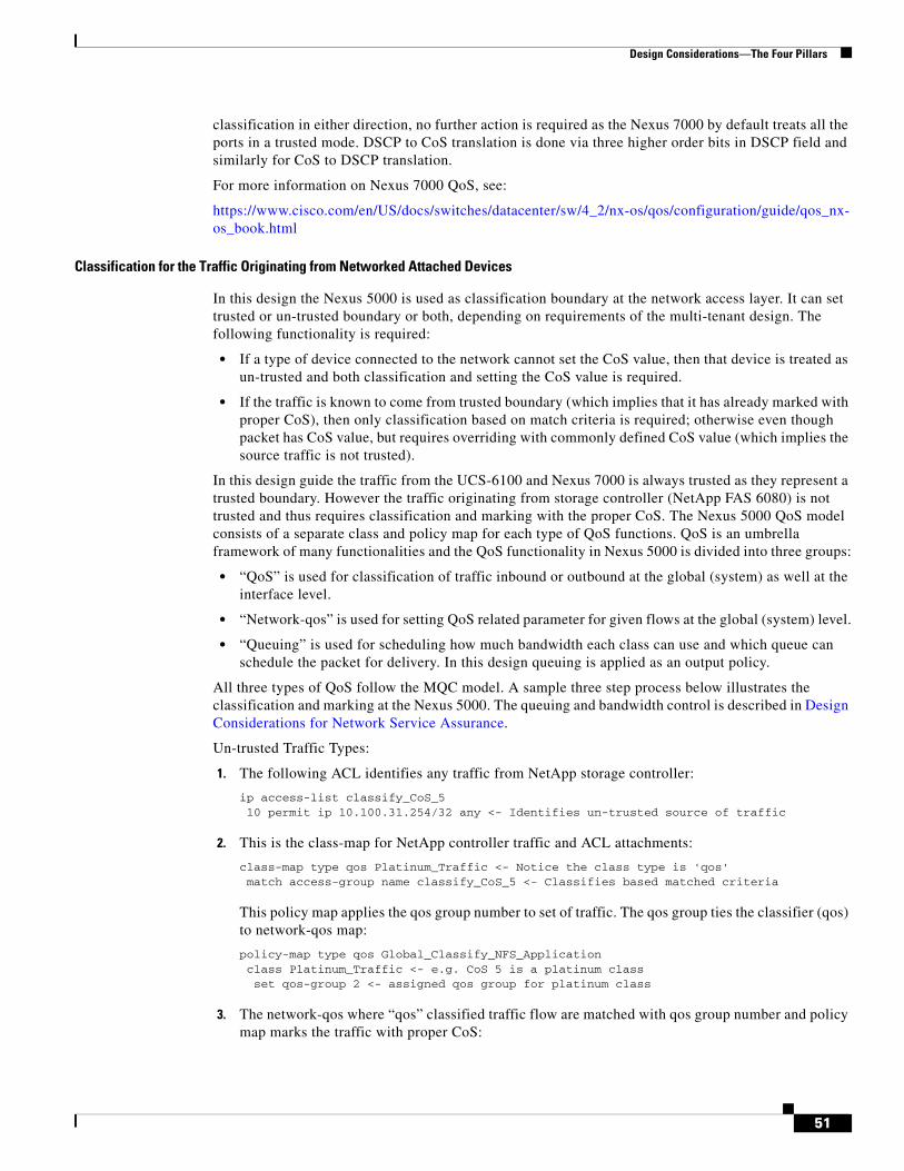
Design Considerations—The Four Pillars
classification in either direction, no further action is required as the Nexus 7000 by default treats all the ports in a trusted mode. DSCP to CoS translation is done via three higher order bits in DSCP field and similarly for CoS to DSCP translation.
For more information on Nexus 7000 QoS, see:
https://www.cisco.com/en/US/docs/switches/datacenter/sw/4_2/nx-os/qos/configuration/guide/qos_nx-os_book.html
Classification for the Traffic Originating from Networked Attached Devices
In this design the Nexus 5000 is used as classification boundary at the network access layer. It can set trusted or un-trusted boundary or both, depending on requirements of the multi-tenant design. The following functionality is required:
• If a type of device connected to the network cannot set the CoS value, then that device is treated as un-trusted and both classification and setting the CoS value is required.
• If the traffic is known to come from trusted boundary (which implies that it has already marked with proper CoS), then only classification based on match criteria is required; otherwise even though packet has CoS value, but requires overriding with commonly defined CoS value (which implies the source traffic is not trusted).
In this design guide the traffic from the UCS-6100 and Nexus 7000 is always trusted as they represent a trusted boundary. However the traffic originating from storage controller (NetApp FAS 6080) is not trusted and thus requires classification and marking with the proper CoS. The Nexus 5000 QoS model consists of a separate class and policy map for each type of QoS functions. QoS is an umbrella framework of many functionalities and the QoS functionality in Nexus 5000 is divided into three groups:
• “QoS” is used for classification of traffic inbound or outbound at the global (system) as well at the interface level.
• “Network-qos” is used for setting QoS related parameter for given flows at the global (system) level.
• “Queuing” is used for scheduling how much bandwidth each class can use and which queue can schedule the packet for delivery. In this design queuing is applied as an output policy.
All three types of QoS follow the MQC model. A sample three step process below illustrates the classification and marking at the Nexus 5000. The queuing and bandwidth control is described in Design Considerations for Network Service Assurance.
Un-trusted Traffic Types:
1. The following ACL identifies any traffic from NetApp storage controller:
ip access-list classify_CoS_5 10 permit ip 10.100.31.254/32 any <- Identifies un-trusted source of traffic
2. This is the class-map for NetApp controller traffic and ACL attachments:
class-map type qos Platinum_Traffic <- Notice the class type is 'qos' match access-group name classify_CoS_5 <- Classifies based matched criteria
This policy map applies the qos group number to set of traffic. The qos group ties the classifier (qos) to network-qos map:
policy-map type qos Global_Classify_NFS_Application class Platinum_Traffic <- e.g. CoS 5 is a platinum class set qos-group 2 <- assigned qos group for platinum class
3. The network-qos where “qos” classified traffic flow are matched with qos group number and policy map marks the traffic with proper CoS:
51
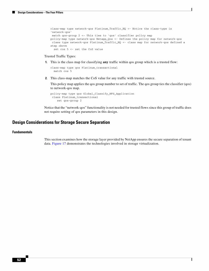
Design Considerations—The Four Pillars
class-map type network-qos Platinum_Traffic_NQ <- Notice the class-type is 'network-qos' match qos-group 2 <- This ties to 'qos' classifier policy map policy-map type network-qos Netapp_Qos <- Defines the policy map for network-qos class type network-qos Platinum_Traffic_NQ <- class map for network-qos defined a step obove set cos 5 <- set the CoS value
Trusted Traffic Types:
1. This is the class map for classifying any traffic within qos group which is a trusted flow:
class-map type qos Platinum_transactional match cos 5
2. This class-map matches the CoS value for any traffic with trusted source.
This policy map applies the qos group number to set of traffic. The qos group ties the classifier (qos) to network-qos map.
policy-map type qos Global_Classify_NFS_Application class Platinum_transactional set qos-group 2
Notice that the “network-qos” functionality is not needed for trusted flows since this group of traffic does not require setting of qos parameters in this design.
Design Considerations for Storage Secure Separation
Fundamentals
This section examines how the storage layer provided by NetApp ensures the secure separation of tenant data. Figure 17 demonstrates the technologies involved in storage virtualization.
52
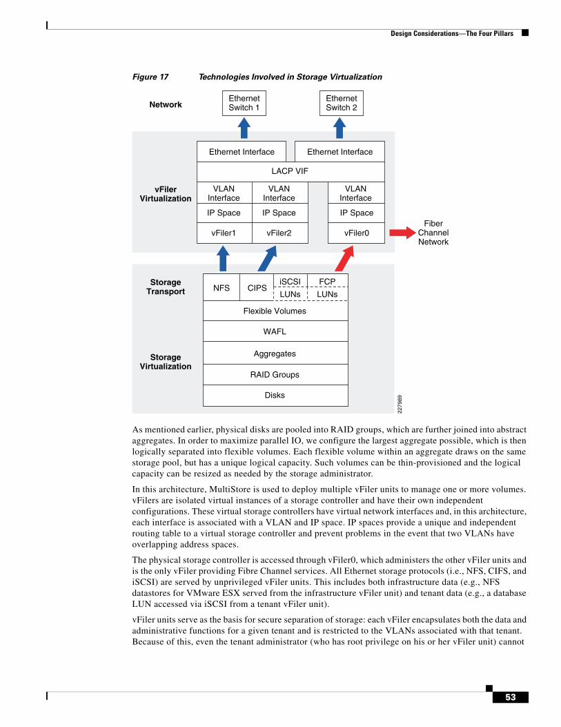
Design Considerations—The Four Pillars
Figure 17 Technologies Involved in Storage Virtualization
As mentioned earlier, physical disks are pooled into RAID groups, which are further joined into abstract aggregates. In order to maximize parallel IO, we configure the largest aggregate possible, which is then logically separated into flexible volumes. Each flexible volume within an aggregate draws on the same storage pool, but has a unique logical capacity. Such volumes can be thin-provisioned and the logical capacity can be resized as needed by the storage administrator.
In this architecture, MultiStore is used to deploy multiple vFiler units to manage one or more volumes. vFilers are isolated virtual instances of a storage controller and have their own independent configurations. These virtual storage controllers have virtual network interfaces and, in this architecture, each interface is associated with a VLAN and IP space. IP spaces provide a unique and independent routing table to a virtual storage controller and prevent problems in the event that two VLANs have overlapping address spaces.
The physical storage controller is accessed through vFiler0, which administers the other vFiler units and is the only vFiler providing Fibre Channel services. All Ethernet storage protocols (i.e., NFS, CIFS, and iSCSI) are served by unprivileged vFiler units. This includes both infrastructure data (e.g., NFS datastores for VMware ESX served from the infrastructure vFiler unit) and tenant data (e.g., a database LUN accessed via iSCSI from a tenant vFiler unit).
vFiler units serve as the basis for secure separation of storage: each vFiler encapsulates both the data and administrative functions for a given tenant and is restricted to the VLANs associated with that tenant. Because of this, even the tenant administrator (who has root privilege on his or her vFiler unit) cannot
vFilerVirtualization
Network
StorageTransport
StorageVirtualization
EthernetSwitch 1
EthernetSwitch 2
Ethernet Interface Ethernet Interface
LACP VIF
VLANInterface
IP Space
vFiler1
VLANInterface
VLANInterface
IP Space
Flexible Volumes
FiberChannelNetwork
Aggregates
RAID Groups
WAFL
Disks
NFS CIPSiSCSI
LUNs
FCP
LUNs
vFiler2
IP Space
vFiler0
2279
89
53
Design Considerations—The Four Pillars
connect to another tenant’s vFiler unit, let alone access the data managed by it. Further, the Ethernet storage network has strict access control implemented to block any IP traffic other than the defined storage, backup, and administration protocols.
Cloud Administrator Perspective
Every IT organization requires certain administrative infrastructure components in order to provide the necessary services and resources to end users. These components within the secure cloud architecture include various physical and virtual objects including storage containers and storage controllers. While these objects play an important role in maintaining overall cloud operations, from a security aspect they are treated exactly the same as tenant resources and are isolated from other tenants as such. The infrastructure Ethernet storage (i.e., NFS for ESX datastore, iSCSI for the vCenter database, etc.) is separated onto its own non-routed VLAN. The Fibre Channel SAN used to boot the ESX hosts is isolated because tenants have no access to Fibre Channel initiators—the only initiators present are the HBAs within each UCS blade. Even within a VLAN, all management traffic is configured to use only secure protocols (HTTPS, SSH, etc.), and local firewalls and port restrictions are enabled where appropriate.
The cloud administrator configures all storage containers, both physical (aggregates) and virtual (flexible volumes) and then assigns virtual storage containers to individual tenant vFilers in the form of flexible volumes. Once a flexible volume has been assigned to a tenant vFiler unit, the tenant may export the flexible volume directly via NAS protocols or further re-distribute storage via block base LUNs or lower level directories called Qtrees. Because the cloud administrator owns all storage allocations, tenants can only use the storage directly allocated to their vFiler unit. If additional storage is needed, the cloud administrator may resize the currently allocated flexible volume(s) for that tenant or assign an additional flexible volume. Tenants cannot use more storage than they are allocated and the ability to allocate storage capacity is limited to the cloud administrator, who can responsibly manage storage resources among the tenants.
Tenant Perspective
Each tenant possesses their own authentication measures for both administrative and data access to their vFiler unit and its underlying storage resources. Tenant administrators can choose the necessary export method and security exports between application and storage. As an example, a tenant administrator can create custom NFS export permissions for their assigned storage resources or export storage via LUNs and leverage iSCSI with CHAP between their application VMs and storage. The method by which application and/or user data is accessed from a tenant’s vFiler unit is customizable by the tenant administrator. This creates a clean separation between storage provisioning (undertaken by the cloud administrator) and storage deployment (managed by the tenant administrator).
Service AssuranceService Assurance is the third pillar that provides isolated compute, network, and storage performance during both steady state and non-steady state. For example, the network can provide each tenant with a certain bandwidth guarantee using QoS, resource pools within VMware help balance and guarantee CPU and memory resources, while FlexShare can balance resource contention across storage volumes.
54
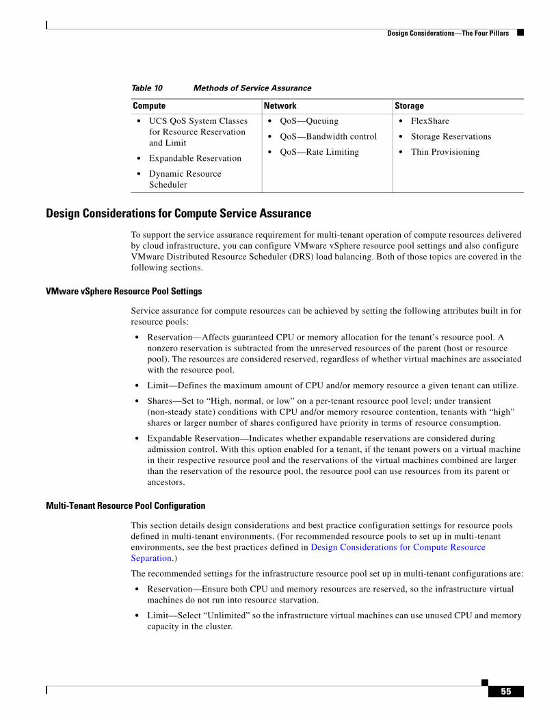
Design Considerations—The Four Pillars
Design Considerations for Compute Service Assurance
To support the service assurance requirement for multi-tenant operation of compute resources delivered by cloud infrastructure, you can configure VMware vSphere resource pool settings and also configure VMware Distributed Resource Scheduler (DRS) load balancing. Both of those topics are covered in the following sections.
VMware vSphere Resource Pool Settings
Service assurance for compute resources can be achieved by setting the following attributes built in for resource pools:
• Reservation—Affects guaranteed CPU or memory allocation for the tenant’s resource pool. A nonzero reservation is subtracted from the unreserved resources of the parent (host or resource pool). The resources are considered reserved, regardless of whether virtual machines are associated with the resource pool.
• Limit—Defines the maximum amount of CPU and/or memory resource a given tenant can utilize.
• Shares—Set to “High, normal, or low” on a per-tenant resource pool level; under transient (non-steady state) conditions with CPU and/or memory resource contention, tenants with “high” shares or larger number of shares configured have priority in terms of resource consumption.
• Expandable Reservation—Indicates whether expandable reservations are considered during admission control. With this option enabled for a tenant, if the tenant powers on a virtual machine in their respective resource pool and the reservations of the virtual machines combined are larger than the reservation of the resource pool, the resource pool can use resources from its parent or ancestors.
Multi-Tenant Resource Pool Configuration
This section details design considerations and best practice configuration settings for resource pools defined in multi-tenant environments. (For recommended resource pools to set up in multi-tenant environments, see the best practices defined in Design Considerations for Compute Resource Separation.)
The recommended settings for the infrastructure resource pool set up in multi-tenant configurations are:
• Reservation—Ensure both CPU and memory resources are reserved, so the infrastructure virtual machines do not run into resource starvation.
• Limit—Select “Unlimited” so the infrastructure virtual machines can use unused CPU and memory capacity in the cluster.
Table 10 Methods of Service Assurance
Compute Network Storage
• UCS QoS System Classes for Resource Reservation and Limit
• Expandable Reservation
• Dynamic Resource Scheduler
• QoS—Queuing
• QoS—Bandwidth control
• QoS—Rate Limiting
• FlexShare
• Storage Reservations
• Thin Provisioning
55
Design Considerations—The Four Pillars
• Shares—A setting of “High” is recommended to ensure infrastructure virtual machines always get a fair share of CPU and memory resources.
• Expandable Reservation—This option does not need to be set as the resource reservation can be increased to accommodate new infrastructure virtual machine additions. The infrastructure virtual machines are expected to remain in a steady state until the shared services infrastructure has scaled up or out. Resource reservations can be adjusted to accommodate any new resource needs.
The recommended settings for the “parent” tenant resource pool set up in multi-tenant configurations are:
• Reservation—Ensure both CPU and memory resources are reserved for allocation to individual tenants.
• Limit—Set this value to be greater than or equal to current CPU and memory reservation.
• Shares—”High” is recommended to ensure tenant and infrastructure resource pools have equal access to CPU and memory resources.
• Expandable Reservation—Should typically be enabled as resource utilization by all tenants may vary widely. Having this option enabled allows tenants to utilize unused CPU and memory capacity at times of critical need (such as quarter/year end for a tenant running applications to record sales transactions).
The recommended settings for individual tenant resource pools set up in multi-tenant configurations are:
• Reservation—Reserve CPU and memory capacity based on tenant’s SLA.
• Limit—Limit value should be set equal to reservation value.
• Shares—Value should be set based on tenant’s SLA.
• Expandable Reservation—Option can be set for tenants with the highest SLA requirements.
VMware DRS Load Balancing
VMware Distributed Resource Scheduler (DRS) can be set to be fully automated at the cluster level so the infrastructure and tenant virtual machine loads are evenly distributed across all of the ESX Server hosts in the cluster.
Note The vShield virtual machine for each ESX host should have the DRS automation level “disabled”.
Design Considerations for Network Service Assurance
Secure Separation introduced a QoS separation method used as a foundation to differentiate the application flows and storage IO requirement upon which the services assurance model is built. Service assurance provides the resilient framework for developing the services level in multi-tenant design. The services assurance at network layer addresses two distinct design requirements for both control function and tenant user data plane of the multi-tenant infrastructure:
• Network Resources Performance Protection (Steady State)
• Network Resources Performance Protection (Non-Steady State)
56
Design Considerations—The Four Pillars
Network Resources Performance Protection (Steady State)
This functionality addresses how to protect the service level for each traffic types and services class in steady state. In a normal operation, the networking resources should be shared and divided to meet the stated goal of the service or protection. Once the traffic is separated based on services level, the shared bandwidth offered at the network layer must be segmented to reflect the services priority defined by CoS field. There are two distinct methods to provide steady state performance protection:
• Queuing—Queuing allows the networking devices to schedule a packet delivery based on the classification criteria. The end effect of the ability to differentiate which packet can get a preferential delivery is to provide the differentiation in terms of response time for applications when oversubscription occurs. The oversubscription is a general term used for defining resources congestion that can occur for variety of reasons in various spaces of a multi-tenant environment. Some examples that can trigger a change in resources map (oversubscription) are failure of multi-tenant components (compute, storage, or network), unplanned application deployment causing high bandwidth usage, or aggregation layer in the network supporting multiple unified fabric. It is important to be aware that the queuing only takes effect when a given bandwidth availability is fully utilized by all the services classes. As described in Architecture Overview, the compute layer (UCS) usually offers 1:1 subscription ratio and storage controller offers enough bandwidth that queuing may not be occurring all the time. However, it is critically important to address the functional requirement of multi-tenant design that one cannot always be sure about overuse of resources. The congestion always occurs in the end-to-end system, whether it hidden inside application structure, VM NIC, CPU, or at the network layer. The oversubscription is elastic and thus the choke points move at various levels in the end-to-end systems. It is the ability of the queuing capability in each networking device to handle such dynamic events that determines the quality of service level.
This queuing capability is available at all layers of network, albeit with some differences in how it functions in each device. The capability of each devices and design recommendation is addressed below.
• Bandwidth Control—As discussed above, queuing allows managing the application response time by matching the order in which queues gets serviced, however it does not control the bandwidth management per queuing (service) class. Bandwidth control allows network devices an appropriate amount of buffers per queue such that certain classes of traffic do not over utilize the bandwidth, allowing other queues to have a fair chance to serve the needs of the rest of the services classes. Bandwidth control goes hand in hand with queuing, as queuing provides the preference on which packet are delivered first, while bandwidth provides how much data can be sent per queue.
QoS-Based Separation describes the types of traffic and services classification based on the service level requirements. In that section each services class is mapped a queue with appropriate CoS mapping. Once the traffic flow is mapped to the proper queue, the bandwidth control is applied per queue. The queue mapping shown in Table 5 is developed based on the minimum queuing class available based on end-to-end network capability. The design principles applied to selecting queuing and bandwidth control requires the capability of following attributes in a multi-tenant design.
Topology—The multi-tenant design goal is to offer scalability and flexibility in services offering. The three tier model selected in this design has a flexibility and management point of selectively choosing the technique at each layer. In the new paradigm of unification of access layer technologies (storage and data) and topologies (Fiber Channel, Ethernet, and eventually FCoE) requires careful treatment of application and IO requirements. In a multi-tenant environment this translates into enabling necessary control and service level assurance of application traffic flows per tenant. If the aggregation and access layer is collapsed the QoS functionality and bandwidth control gets difficult since the traffic flow characteristic changes with two-tier model. For example, the traffic from VM to VM may have to flow through the access layer switch since the dual-fabric design requires the traffic to exit the fabric and be redirected via an access layer switch that has a knowledge of the mac-address reachability. With a two
57

Design Considerations—The Four Pillars
tier design, the Layer 3 and Layer 2 functionality may get merged and thus one has to manage Layer 3 to Layer 2 flows, marking/classification between Layer 3 and Layer 2; aggregation-to-aggregation flows are now mixed with access layer flows (VM to VM). Thus traffic management and bandwidth control can be complex as the environment grows with diverse VM-to-VM or aggregation-to-aggregation flows supporting diverse communication connectivity. The unified access layer with Nexus 5000 allows control of the bandwidth and queuing, specifically targeting the traffic flow behavior at the edge for compute, storage, and networking.
Oversubscription Model (Congestion Management Point)
In this design UCS represents unified edge resources where the consolidation of storage IO and IP data communicates via 10G interfaces available at each blade. UCS is designed with a dual-fabric model in which each data path from individual blades eliminates the network bandwidth level oversubscription all the way up to UCS 6100 fiber interconnects. However, when UCS is used in multi-tenant environment the need for service level for each tenant(s) (which are sharing the resources in a homogeneous way) requires managment of the bandwidth within the UCS as well as at the aggregation point (Fiber Interconnects) where multiple UCS can be connected. There are many oversubscription models depending upon the tired structure and the access-to-aggregation topologies.
In this design working from compute layer up to Layer 3, the major boundaries where oversubscriptions can occur are:
• VM to UCS Blades—The density of VM and application driving VM network activity can oversubscribe 10G interface. Notice that Nexus 1000V switch providing virtual Ethernet connectivity is not a gated interface; in other words, it is an abstraction of physical Ethernet and thus offers no signaling level limit that exists in physical Ethernet. Major communication flow that can occur is between VM to VM either within the blade or residing on a different blade; the later flow behavior overlaps fiber interconnect boundary (described below) since those VM-to-VM communications must flow through the 6100 to an access layer switch.
• Fiber Interconnect to access layer—The uplinks from UCS 6100 determines the oversubscription ratio purely from the total bandwidth offered to UCS systems, since each UCS systems can offer up to 80 GBps of traffic to UCS 6100. The maximum number of 10GBps links that can be provisioned from a UCS 6100 (from each fabric) is eight; the resulting oversubscription could be 2:1 or 4:1 depending on number of UCS systems connected. In the future uplink capacity may rise to sixteen 10GBps links. The fiber interconnect manages the application flows (both direction) for two major categories of traffic:
– Back-end user data traffic—VM to VM (either VM residing on separate blade or to other UCS system in a domain)
– VM to storage (NFS datastore and Application IO per tangent)—Front end user data traffic-VM to users in each tenant
The UCS 6100 upstream (towards users and storage) traffic queuing and bandwidth control is designed based on services classes defined in QoS-Based Separation. The UCS QoS class capability and CoS mapping based on traffic classes is shown in Table 11. The queuing capability of UCS 6100 is integrated with the QoS services classes it offers. In other words, QoS systems class is mapped to CoS mapping; e.g., platinum class when assigned CoS value of 5, the CoS-5 is treated as priority class and is given a first chance to deliver the packet. Notice also that the Gold class is designated at “no-drop” calls to differentiate the IO and transactional services class based on tenant requirement. The no-drop designated class buffers as much as it can and does not drop the traffic; the resulting behavior is higher latency but bandwidth is guaranteed.
Bandwidth control becomes an important design attribute in managing services level with the unified fabric. Bandwidth control in terms of weights applied to each class is also shown in Table 11. Notice that the weight multiplier can range from 1 to 10. The multiplier automatically adjusts the total bandwidth
58

Design Considerations—The Four Pillars
percentage to 100%. Table 11 does not reflect the bandwidth controlled applicable to a multi-tenant design, as effective values are highly dependent on application and user tenant requirements. However, platinum class requires a careful bandwidth allocation since the traffic in this class is treated with higher priority and unlimited bandwidth (NFS datastore attach and platinum tenant application IO).
The weight of 1 is referred as best-effort, however that does not mean the traffic inthe respective class is treated as best-effort.
Table 11 shows the weight of one (1) is applied to all classes; the effective bandwidth is divided in equal multiple of five (total classes) (essentially a ratio of a weight of the class to total of weight presented as percentage of bandwidth as whole number).
For additional information on UCS 6100 QoS, see:
http://www.cisco.com/en/US/docs/unified_computing/ucs/sw/gui/config/guide/GUI_Config_Guide_chapter16.html
Within the access layer—The oversubscription at this boundary is purely a function of how many access layer devices are connected and how much inter-devices traffic management is required. Two major categories of application flow that require management:
• Back-end traffic (storage IO traffic)—In this design the storage controller (NetApp FAS 6080) is connected to Nexus 5000 with two 10GBps link forming a single EtherChannel. The NFS datastore traffic flow is composed of ESX host and guest VM operation, which is the most critical flow for the integrity of the entire multi-tenant environment. Per-tenant application traffic flow to a storage controller requires the management based on services level described in QoS-Based Separation. This design guide assumes that each tenant vFiler unit is distributed over dual-controller and thus offers up to 40 GBps bandwidth (the FAS6080 can have up to a maximum of 5 dual port 10Gb adapters, thus ten 10Gbpbs ports per controller and supports up to eight active interfaces per LACP group) and thus oversubscription possibility for managing the traffic from storage is reduced. However, the traffic flow upstream to the VM (read IO) is managed at the Nexus 5000 with bandwidth control.
• Front-end user traffic—In this design application flows from VM to user tenant are classified with per tangent services class. The front-end user traffic requires bandwidth control on upstream as well as downstream. Upstream (to the user) bandwidth control should reflect the total aggregate bandwidth from all networked devices (in this design primarily UCS systems). The downstream (to the VM) bandwidth control can be managed per class at Nexus 7000 or Nexus 5000. In this design Nexus 5000 is used at the bandwidth control point; future designs shall incorporate the Nexus 7000 option.
The Nexus 5000 QoS components are described in QoS-Based Separation. The queuing and bandwidth capability reflecting above requirements are shown in Table 12. In Nexus 5000, queuing can be applied to global or at the interface level. In general it is a good design practice to keep the queuing policy global,
Table 11 UCS—Queuing and Bandwidth Mapping
QoS System Class CoS Mapping Drop Criteria Weight (1-10) Effective BW%
Platinum 5 Tail Drop 1 (best-effort) 20
Gold 6 No Drop 1 (best-effort) 20
Silver 4 Tail Drop 1 (best-effort) 20
Bronze 2 Tail Drop 1 (best-effort) 20
FCoE 3 Not Used Not Used
Default 0,1 Tail Drop 1 (best-effort) 20
59
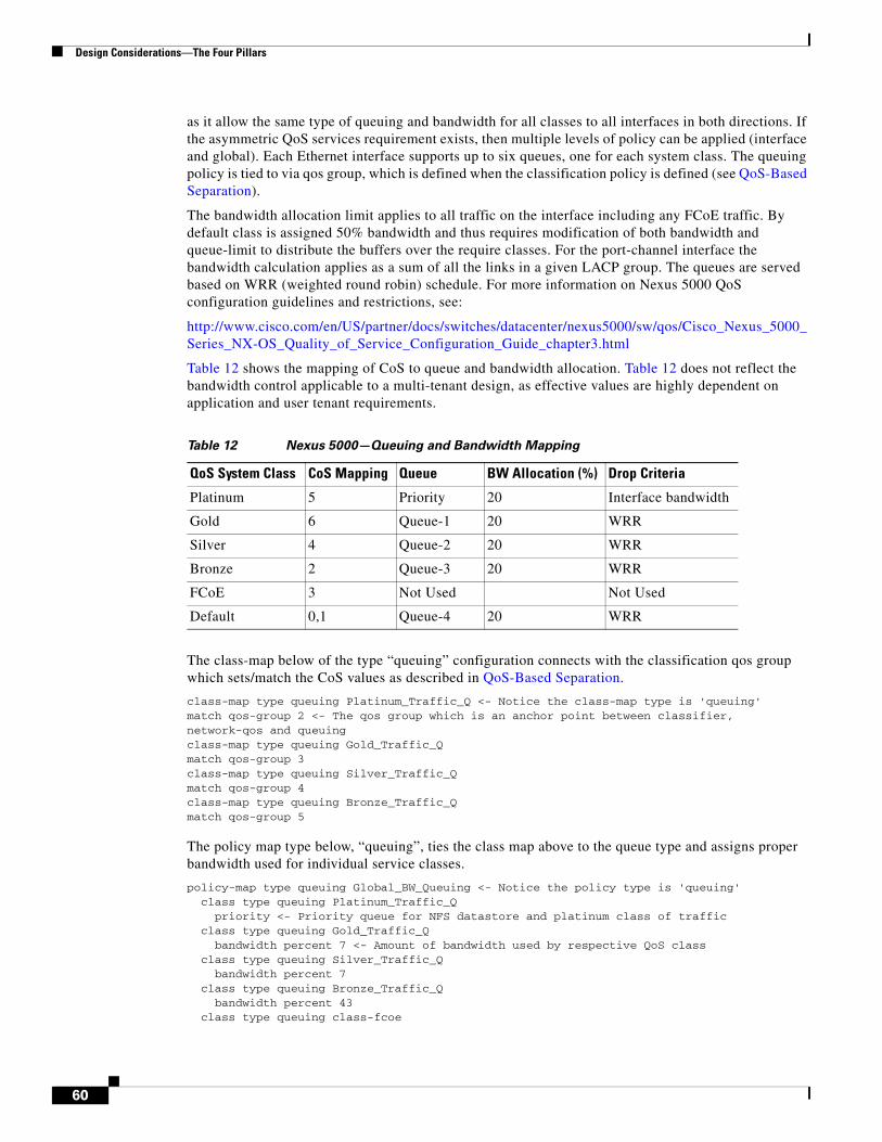
Design Considerations—The Four Pillars
as it allow the same type of queuing and bandwidth for all classes to all interfaces in both directions. If the asymmetric QoS services requirement exists, then multiple levels of policy can be applied (interface and global). Each Ethernet interface supports up to six queues, one for each system class. The queuing policy is tied to via qos group, which is defined when the classification policy is defined (see QoS-Based Separation).
The bandwidth allocation limit applies to all traffic on the interface including any FCoE traffic. By default class is assigned 50% bandwidth and thus requires modification of both bandwidth and queue-limit to distribute the buffers over the require classes. For the port-channel interface the bandwidth calculation applies as a sum of all the links in a given LACP group. The queues are served based on WRR (weighted round robin) schedule. For more information on Nexus 5000 QoS configuration guidelines and restrictions, see:
http://www.cisco.com/en/US/partner/docs/switches/datacenter/nexus5000/sw/qos/Cisco_Nexus_5000_Series_NX-OS_Quality_of_Service_Configuration_Guide_chapter3.html
Table 12 shows the mapping of CoS to queue and bandwidth allocation. Table 12 does not reflect the bandwidth control applicable to a multi-tenant design, as effective values are highly dependent on application and user tenant requirements.
The class-map below of the type “queuing” configuration connects with the classification qos group which sets/match the CoS values as described in QoS-Based Separation.
class-map type queuing Platinum_Traffic_Q <- Notice the class-map type is 'queuing'match qos-group 2 <- The qos group which is an anchor point between classifier, network-qos and queuingclass-map type queuing Gold_Traffic_Qmatch qos-group 3class-map type queuing Silver_Traffic_Qmatch qos-group 4class-map type queuing Bronze_Traffic_Qmatch qos-group 5
The policy map type below, “queuing”, ties the class map above to the queue type and assigns proper bandwidth used for individual service classes.
policy-map type queuing Global_BW_Queuing <- Notice the policy type is 'queuing' class type queuing Platinum_Traffic_Q priority <- Priority queue for NFS datastore and platinum class of traffic class type queuing Gold_Traffic_Q bandwidth percent 7 <- Amount of bandwidth used by respective QoS class class type queuing Silver_Traffic_Q bandwidth percent 7 class type queuing Bronze_Traffic_Q bandwidth percent 43 class type queuing class-fcoe
Table 12 Nexus 5000—Queuing and Bandwidth Mapping
QoS System Class CoS Mapping Queue BW Allocation (%) Drop Criteria
Platinum 5 Priority 20 Interface bandwidth
Gold 6 Queue-1 20 WRR
Silver 4 Queue-2 20 WRR
Bronze 2 Queue-3 20 WRR
FCoE 3 Not Used Not Used
Default 0,1 Queue-4 20 WRR
60
Design Considerations—The Four Pillars
bandwidth percent 0 fclass type queuing class-default bandwidth percent 43
The QoS function is enabled via global configuration mode. In this design all functionality of QoS is applied at the global level.
system qos service-policy type queuing output Global_BW_Queuing <- Applies queuing to all interfaces service-policy type qos input Global_Classify_NFS_Application <- Classifies traffic based on service class service-policy type network-qos Netapp_Qos <- QOS parameter setting
Caution This design utilizes the VPC technology to enable loop-less design. The VPC configuration mandates that both Nexus 5000s be configured with consistent set of global configuration. It is recommended to enable QoS polices at the systems level before the VPC is enabled. If the QoS configuration is applied after the VPC configuration, both Nexus 5000s must enable the QoS simultaneously. Failure to follow this practice would disable all the VLANs belonging to VPC topology.
Network Resources Performance Protection (Non-Steady State)
This functionality addresses how to protect the services level for each traffic type and services class in a non-steady state. Non-steady state is defined by any change in the resources pool, such as a failure of any component of a multi-tenant environment; vMotion or new VM provisioning can affect the existing resources commitment or protection of application flows. Non-steady state performance is often identified as a set of events that triggers the misbehaviour of or over commitment of resources.
In a multi-tenant environment, tenants must be protect from each other. In practice, a tenant may require resources in which application and IO traffic may drastically vary from normal usage. In other cases a tenant environment may have been exposed to a virus, generating abnormal amounts of traffic. In either case, a set of policy controls can be enabled such that any un-predictable change in traffic pattern can be either treated softly by allowing applications to burst/violate for some time above the service commitment or by a hard policy to drop the excess or cap the rate of transmission. This capability can also be used to define service level such that non-critical services can be kept at a certain traffic level or the lowest service level traffic can be capped such that it cannot influence the higher-end tenant services. Policing as well as rate-limiting is used to define such services or protection levels. These tools are applied as close to the edge of the network as possible, since it is intuitive to stop the traffic from entering the network. In this design Nexus 1000V is used as policing and rate-limiting function for three types of traffic:
• vMotion—vMotion is used for live VM migration. The vMotion traffic requirement can vary for each environment as well as VM configuration. VMware traditionally recommends dedicated Gigabit interface for vMotion traffic. In this design the vMotion traffic has been dedicated with non-routable VMkernel port. The traffic for the vMotion from each blade-sever is kept at 1 GBps to reflect the traditional environment. This limit can either be raised or lowered based on requirements, however the design should consider that vMotion is run to completion event (thus it may take longer with lower bandwidth, but will complete in time) and should not be configured such that the resulting traffic rate impacts critical traffic, such as NFS datastore.
• Differentiated transactional and storage services—In a multi-tenant design, various methods are employed to generate a differentiated services. For example, “priority” queue is used for the most critical services and “no-drop” is used for traffic that cannot be dropped, but can sustain some delay. Rate-limiting is used for services that are often called fixed rate services, in which each application
61
Design Considerations—The Four Pillars
class or service traffic is capped at a certain level, beyond which the traffic is either dropped or marked with high probability drop CoS. In this design silver traffic is designated as fixed rate services and rate-limited at the edge of the network.
• Management—In this design guide the services console interface (VLAN) is merged into a common management VLAN designated for all the resources. Traditionally the ESX console is provided a dedicated 1GBps interface, however in practical deployments the bandwidth requirement for managements function is well below 1GBps. UCS enables non-blocking 10Gps access bandwidth, and so offers bandwidth in excess of 1GBps. However, the management VLAN should be enabled with rate-limiting to cap the traffic at 1GBps.
For Nexus 1000V rate-limiting configuration and restriction guidelines, see:
http://www.cisco.com/en/US/docs/switches/datacenter/nexus1000/sw/4_0/qos/configuration/guide/qos_4policing.html
Traffic Engineering with End-to-End Service Assurance
QoS-Based Separation and Design Considerations for Network Service Assurance developed a design model for a multi-tenant environment. In this design, multiple types of traffic use the same class of service, which in turn uses the same queue/interface. With UCS redundant fabric (A & B) capability and mac-pining feature available in the 4.0(4)SV1(2) release for Nexus 1000V, it is possible to add the diversity in managing the traffic in steady state condition. Dual fabric in UCS in conjunction with mac-pining enables the possibility of traffic engineering such that service class can split its traffic types. Effectively allowing to double the classification buckets available. Off-course during the failure of a fabric all traffic types will use the same path and resources. One of the big advantages of static pinning is to migrate the active/standby design that customers have been deploying with VMware vSwitch.
The mac-pining is configured under each port-profiles such when a port-profiles is attached the VM interfaces, any traffic from that interface mac-address is pinned to a given fabric id, which can be either 0 or 1. In the case of a failure of any component along the path the Nexus 1000V uplink automatically select the available fabric for recovering the traffic. The following CLI shows the usage of the mac-pining with port-profile:
port-profile type vethernet Control-Packet-NFS vmware port-group switchport mode access switchport access vlan 900 service-policy type qos input Platinum_CoS_5 <- QoS policy marking the traffic with CoS of 5 pinning id 0 <- The traffic from this port-profiled will always use fabric A no shutdown system vlan 900 state enabled
Figure 18 explains the mac-pining capability available in latest Nexus OS release 4.0(4)SV1(2).
62

Design Considerations—The Four Pillars
Figure 18 MAC-Pinning and Failover
The multi-tenant model for all type of traffic and associated services classes along with theirs proposed differentiated services level is described in Table 13. Notice the rational for assigning traffic to various resources (fabric, UCS-class, queue) can vary based on each customer’s preference. The key design point is that with UCS (dual-fabric) and Nexus 1000V (mac-based pining), the customer can traffic engineer the multi-tenant user services level requirement with sufficient diversity.
Port-channel
Sub-group 1Sub-group 0
AfterFailover
2279
92
PC
ServiceConsole vMotion
Port-channel
Sub-group 1
PC
ServiceConsole vMotion
Table 13 End-to-End Traffic Engineering Service Class Map
Traffic TypeClassification Category CoS
Traffic Engineering Fabric/Class Rational
NFS Data Store VMkernel/Control 5 Fab-A/Platinum Live ESX/VM OS Data
Nexus 1000V Control System/Control 5 Fab-A/Platinum Nexus 1000 Operation
Nexus 1000V Packet System/Network-Control
5 Fab-A/Platinum Nexus 1000 Operation
Platinum IO Low Latency, BW Guarantee
Tenant Data 5 Fab-B/Platinum Load-share Fab-B wrt CoS 5 since NFS is in Fab-A
Platinum Transactional
Tenant Data 6 Fab-A/Platinum Time Sensitive Traffic
Nexus 1000V Management
System/Control 6 Fab-B/Gold Split Nexus 1000 control from Fab-A getting all
ESX Service Console vswif/Control 6 Fab-B/Gold Same as above
Gold IO Med Latency, No Drop
Tenant Data 6 Fab-A/Gold DCE to buffer
Load-share Fab-A, since platinum-IO is on Fab-A
Gold Transactional Tenant Data 6 Fab-B/Gold Time Sensitive Traffic
vMotion VMkernel/Control 4 Fab-A/Silver Rate Limited/not often, run to completion
Silver Transactional Tenant Data 4 Fab-A/Silver Competing with vMotion only when vMotion occurs
63
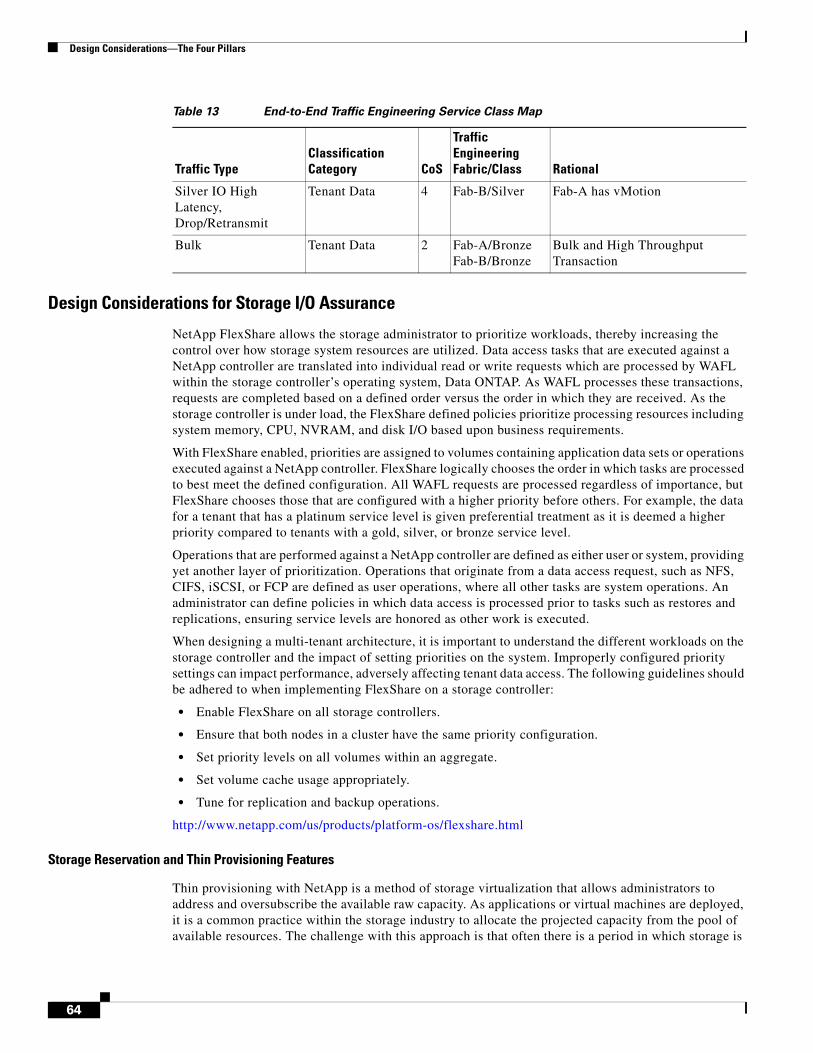
Design Considerations—The Four Pillars
Design Considerations for Storage I/O Assurance
NetApp FlexShare allows the storage administrator to prioritize workloads, thereby increasing the control over how storage system resources are utilized. Data access tasks that are executed against a NetApp controller are translated into individual read or write requests which are processed by WAFL within the storage controller’s operating system, Data ONTAP. As WAFL processes these transactions, requests are completed based on a defined order versus the order in which they are received. As the storage controller is under load, the FlexShare defined policies prioritize processing resources including system memory, CPU, NVRAM, and disk I/O based upon business requirements.
With FlexShare enabled, priorities are assigned to volumes containing application data sets or operations executed against a NetApp controller. FlexShare logically chooses the order in which tasks are processed to best meet the defined configuration. All WAFL requests are processed regardless of importance, but FlexShare chooses those that are configured with a higher priority before others. For example, the data for a tenant that has a platinum service level is given preferential treatment as it is deemed a higher priority compared to tenants with a gold, silver, or bronze service level.
Operations that are performed against a NetApp controller are defined as either user or system, providing yet another layer of prioritization. Operations that originate from a data access request, such as NFS, CIFS, iSCSI, or FCP are defined as user operations, where all other tasks are system operations. An administrator can define policies in which data access is processed prior to tasks such as restores and replications, ensuring service levels are honored as other work is executed.
When designing a multi-tenant architecture, it is important to understand the different workloads on the storage controller and the impact of setting priorities on the system. Improperly configured priority settings can impact performance, adversely affecting tenant data access. The following guidelines should be adhered to when implementing FlexShare on a storage controller:
• Enable FlexShare on all storage controllers.
• Ensure that both nodes in a cluster have the same priority configuration.
• Set priority levels on all volumes within an aggregate.
• Set volume cache usage appropriately.
• Tune for replication and backup operations.
http://www.netapp.com/us/products/platform-os/flexshare.html
Storage Reservation and Thin Provisioning Features
Thin provisioning with NetApp is a method of storage virtualization that allows administrators to address and oversubscribe the available raw capacity. As applications or virtual machines are deployed, it is a common practice within the storage industry to allocate the projected capacity from the pool of available resources. The challenge with this approach is that often there is a period in which storage is
Silver IO High Latency, Drop/Retransmit
Tenant Data 4 Fab-B/Silver Fab-A has vMotion
Bulk Tenant Data 2 Fab-A/Bronze Fab-B/Bronze
Bulk and High Throughput Transaction
Table 13 End-to-End Traffic Engineering Service Class Map
Traffic TypeClassification Category CoS
Traffic Engineering Fabric/Class Rational
64
Design Considerations—The Four Pillars
underutilized before the actual capacity used matches the projected requirements. Thin provisioning allows enterprises to purchase storage as required without the need to reconfigure parameters on the hosts that attach to the array. This saves organizations valuable money and time with respect to the initial purchase and subsequent administration overhead for the life of the storage controllers. Thin provisioning provides a level of “storage on demand” as raw capacity is treated as a shared resource pool and is only consumed as needed.
It is recommended practice that when deploying thin provisioned resources, administrators also configure associated management policies on the thinly provisioned volumes within the environment. These policies include volume auto-grow, Snapshot auto-delete, and fractional reserve. Volume auto-grow is a space management feature that allows a volume to grow in defined increments up to a predefined threshold. Snapshot auto-delete is a policy related to the retention of Snapshot copies, protected instances of data, providing an automated method to delete the oldest snapshots when a volume is nearly full. Fractional reserve is a policy that allows the percentage of space reservation to be modified based on the importance of the associated data. When using these features concurrently, platinum level tenants can have priority to upgrade their space requirements. In effect, a platinum tenant would be allowed to grow their volume as needed and the space would be reserved from the shared pool. Conversely, lower level tenants would require additional administrator intervention to accommodate requests for additional storage.
The use of thin provisioning features within a multi-tenant environment provides outstanding ROI as new tenants are deployed and grow requiring more storage. Environments can be architected such that storage utilization is improved without requiring reconfiguration within the UCS and virtualization layer. The use of management policies can distinguish resource allocation afforded to tenants of varying service levels.
For additional details regarding thin provisioning and the latest best practices, see the following technical reports:
• http://media.netapp.com/documents/tr-3563.pdf
• http://media.netapp.com/documents/tr-3483.pdf
ManagementAs the storage demands of multi-tenant environments grow, so do the challenges of managing them. Multi-tenant service providers require comprehensive control and extensive visibility of their shared infrastructure to effectively enable the appropriate separation and service levels for their customers. The varied and dynamic requirements of accommodating multiple customers on a shared infrastructure drive service providers toward storage management solutions that are more responsive and comprehensive while minimizing operational complexity.
In its current form, components within each layer are managed by:
• vCenter
• UCS Manager
• DC Network Manager
• NetApp FilerView (http://www.netapp.com/us/products/platform-os/filerview.html)
• Provisioning Manager (http://www.netapp.com/us/products/management-software/provisioning.html)
• Protection Manager (http://www.netapp.com/us/products/management-software/protection.html)
• SnapManager for Virtual Infrastructure (http://www.netapp.com/us/products/management-software/snapmanager-virtual.html)
65
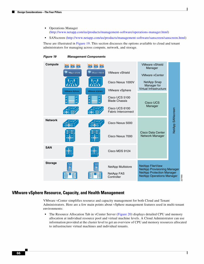
Design Considerations—The Four Pillars
• Operations Manager (http://www.netapp.com/us/products/management-software/operations-manager.html)
• SANscreen (http://www.netapp.com/us/products/management-software/sanscreen/sanscreen.html)
These are illustrated in Figure 19. This section discusses the options available to cloud and tenant administrators for managing across compute, network, and storage.
Figure 19 Management Components
VMware vSphere Resource, Capacity, and Health Management
VMware vCenter simplifies resource and capacity management for both Cloud and Tenant Administrators. Here are a few main points about vSphere management features used in multi-tenant environments:
• The Resource Allocation Tab in vCenter Server (Figure 20) displays detailed CPU and memory allocation at individual resource pool and virtual machine levels. A Cloud Administrator can use information provided at the cluster level to get an overview of CPU and memory resources allocated to infrastructure virtual machines and individual tenants.
Network
Compute
Storage
Cisco Nexus 7000
VMware vShield
VMware vSphere
Cisco UCS 5100Blade Chassis
Cisco UCS 6100Fabric Interconnect
Cisco Nexus 1000V
Cisco Nexus 5000
NetApp Multistore
NetApp FASController
SANCisco MDS 9124
2279
90
Net
App
SA
Nsc
reen
NetApp FilerViewNetApp Provisioning ManagerNetApp Protection ManagerNetApp Operations Manager
Cisco UCSManager
Cisco Data CenterNetwork Manager
VMware vShieldManager
VMware vCenter
NetApp SnapManager for
Virtual Infrastructure
66
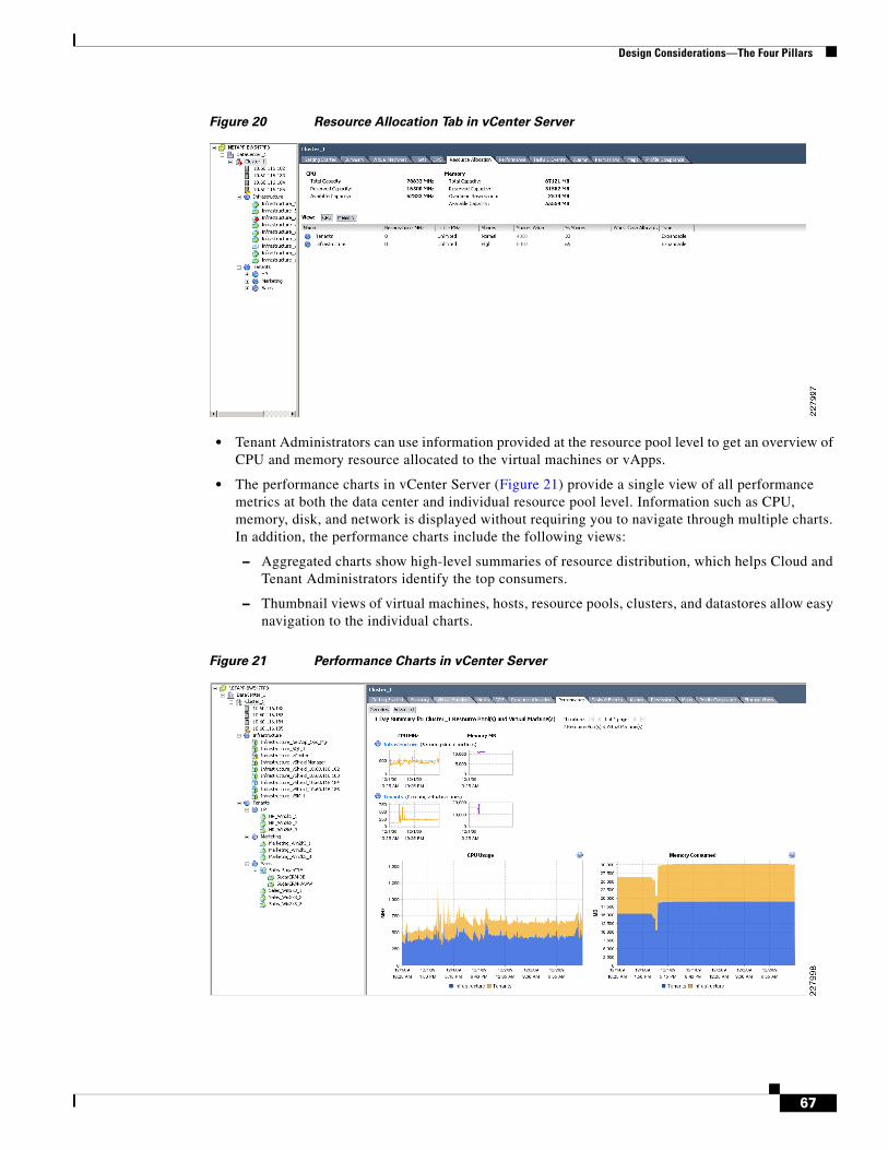
Design Considerations—The Four Pillars
Figure 20 Resource Allocation Tab in vCenter Server
• Tenant Administrators can use information provided at the resource pool level to get an overview of CPU and memory resource allocated to the virtual machines or vApps.
• The performance charts in vCenter Server (Figure 21) provide a single view of all performance metrics at both the data center and individual resource pool level. Information such as CPU, memory, disk, and network is displayed without requiring you to navigate through multiple charts. In addition, the performance charts include the following views:
– Aggregated charts show high-level summaries of resource distribution, which helps Cloud and Tenant Administrators identify the top consumers.
– Thumbnail views of virtual machines, hosts, resource pools, clusters, and datastores allow easy navigation to the individual charts.
Figure 21 Performance Charts in vCenter Server
67
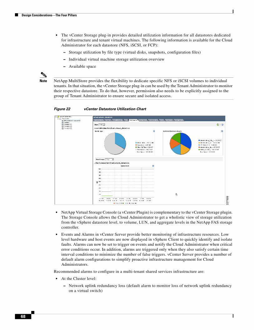
Design Considerations—The Four Pillars
• The vCenter Storage plug-in provides detailed utilization information for all datastores dedicated for infrastructure and tenant virtual machines. The following information is available for the Cloud Administrator for each datastore (NFS, iSCSI, or FCP):
– Storage utilization by file type (virtual disks, snapshots, configuration files)
– Individual virtual machine storage utilization overview
– Available space
Note NetApp MultiStore provides the flexibility to dedicate specific NFS or iSCSI volumes to individual tenants. In that situation, the vCenter Storage plug-in can be used by the Tenant Administrator to monitor their respective datastore. To do that, however, permission also needs to be explicitly assigned to the group of Tenant Administrator to ensure secure and isolated access.
Figure 22 vCenter Datastore Utilization Chart
• NetApp Virtual Storage Console (a vCenter Plugin) is complementary to the vCenter Storage plugin. The Storage Console allows the Cloud Administrator to get a wholistic view of storage utilization from the vSphere datastore level, to volume, LUN, and aggregate levels in the NetApp FAS storage controller.
• Events and Alarms in vCenter Server provide better monitoring of infrastructure resources. Low level hardware and host events are now displayed in vSphere Client to quickly identify and isolate faults. Alarms can now be set to trigger on events and notify the Cloud Administrator when critical error conditions occur. In addition, alarms are triggered only when they also satisfy certain time interval conditions to minimize the number of false triggers. vCenter Server provides a number of default alarm configurations to simplify proactive infrastructure management for Cloud Administrators.
Recommended alarms to configure in a multi-tenant shared services infrastructure are:
• At the Cluster level:
– Network uplink redundancy loss (default alarm to monitor loss of network uplink redundancy on a virtual switch)
68
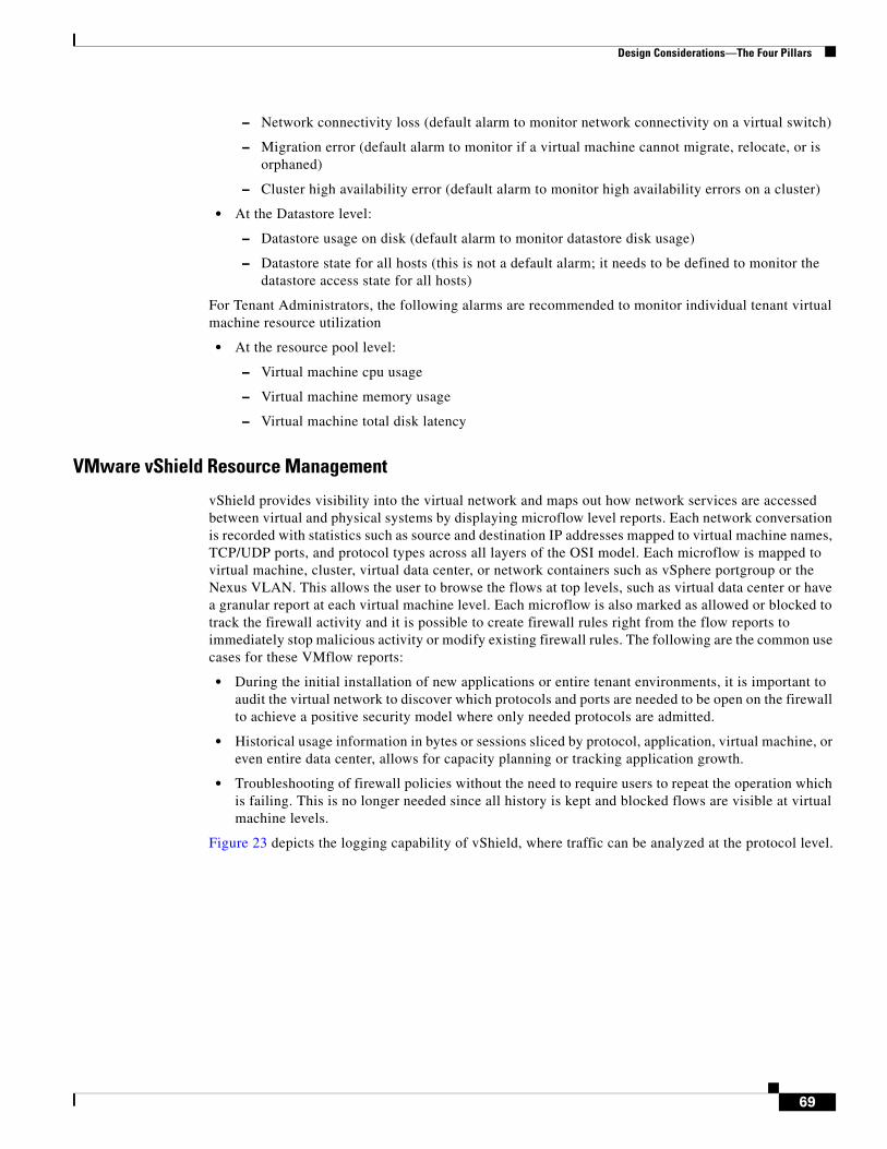
Design Considerations—The Four Pillars
– Network connectivity loss (default alarm to monitor network connectivity on a virtual switch)
– Migration error (default alarm to monitor if a virtual machine cannot migrate, relocate, or is orphaned)
– Cluster high availability error (default alarm to monitor high availability errors on a cluster)
• At the Datastore level:
– Datastore usage on disk (default alarm to monitor datastore disk usage)
– Datastore state for all hosts (this is not a default alarm; it needs to be defined to monitor the datastore access state for all hosts)
For Tenant Administrators, the following alarms are recommended to monitor individual tenant virtual machine resource utilization
• At the resource pool level:
– Virtual machine cpu usage
– Virtual machine memory usage
– Virtual machine total disk latency
VMware vShield Resource Management
vShield provides visibility into the virtual network and maps out how network services are accessed between virtual and physical systems by displaying microflow level reports. Each network conversation is recorded with statistics such as source and destination IP addresses mapped to virtual machine names, TCP/UDP ports, and protocol types across all layers of the OSI model. Each microflow is mapped to virtual machine, cluster, virtual data center, or network containers such as vSphere portgroup or the Nexus VLAN. This allows the user to browse the flows at top levels, such as virtual data center or have a granular report at each virtual machine level. Each microflow is also marked as allowed or blocked to track the firewall activity and it is possible to create firewall rules right from the flow reports to immediately stop malicious activity or modify existing firewall rules. The following are the common use cases for these VMflow reports:
• During the initial installation of new applications or entire tenant environments, it is important to audit the virtual network to discover which protocols and ports are needed to be open on the firewall to achieve a positive security model where only needed protocols are admitted.
• Historical usage information in bytes or sessions sliced by protocol, application, virtual machine, or even entire data center, allows for capacity planning or tracking application growth.
• Troubleshooting of firewall policies without the need to require users to repeat the operation which is failing. This is no longer needed since all history is kept and blocked flows are visible at virtual machine levels.
Figure 23 depicts the logging capability of vShield, where traffic can be analyzed at the protocol level.
69
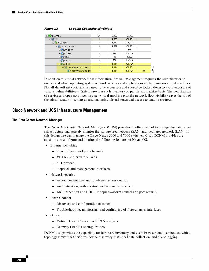
Design Considerations—The Four Pillars
Figure 23 Logging Capability of vShield
In addition to virtual network flow information, firewall management requires the administrator to understand which operating system network services and applications are listening on virtual machines. Not all default network services need to be accessible and should be locked down to avoid exposure of various vulnerabilities—vShield provides such inventory on per virtual machine basis. The combination of service and open port inventory per virtual machine plus the network flow visibility eases the job of the administrator in setting up and managing virtual zones and access to tenant resources.
Cisco Network and UCS Infrastructure Management
The Data Center Network Manager
The Cisco Data Center Network Manager (DCNM) provides an effective tool to manage the data center infrastructure and actively monitor the storage area network (SAN) and local area network (LAN). In this design one can manage the Cisco Nexus 5000 and 7000 switches. Cisco DCNM provides the capability to configure and monitor the following features of Nexus-OS.
• Ethernet switching
– Physical ports and port channels
– VLANS and private VLANs
– SPT protocol
– loopback and management interfaces
• Network security
– Access control lists and role-based access control
– Authentication, authorization and accounting services
– ARP inspection and DHCP snooping—storm control and port security
• Fibre-Channel
– Discovery and configuration of zones
– Troubleshooting, monitoring, and configuring of fibre-channel interfaces
• General
– Virtual Device Context and SPAN analyzer
– Gateway Load Balancing Protocol
DCNM also provides the capability for hardware inventory and event browser and is embedded with a topology viewer that performs device discovery, statistical data collection, and client logging.
70
Design Considerations—The Four Pillars
UCS Manager
The UCS platform is managed by a HTTP-based GUI interface. UCS manager provides a single point of management for the UCS system and manages all devices within UCS as a single logical entity. All configuration tasks, operational management, and troubleshooting can be performed through the UCS management interface. The following is a summary of the basic functionality provided by the UCS manager:
• It manages the fabric interconnect, the chassis, the servers, the fabric extender, and the adapters.
• It provides hardware management, such as chassis and server discovery, firmware management, and backup and configuration restore functionality.
• It manages system wide pools that can be shared by all the servers within the chassis. These pools include MAC pools, World Wide Node Name (WWNN) pools, World Wide Port Name (WWPN) pools, and the Universally Unique Identifier Suffix (UUID) pools.
• It can be used to define service-profiles, which is a logical representation of a physical server that includes connectivity as well as identity information.
• Creating an organizational hierarchy as well as role-based-access control.
• Creating configurational and operational policies that determines how the system behaves under specific circumstances. Some of the policies that can be set include:
– Boot policy—Determines the location from which the server boots
– QOS definition policy—Determines the outgoing QoS parameters for a vNIC or vHBA
– Server discovery policy—Determines how system reacts when a new server is discovered
– Server pool policy—Qualifies servers based on parameters such as memory and processor power
– Firmware policy—Determines a firmware version that will be applied to a server
– Port, adapter, blade, and chassis policy—Defines intervals for collection and reporting of statistics for ports, adapter, blades, and chassis respectively
Deploying DCNM and Using UCS Manager in a Secure Cloud
A stateless computing model dictates that booting from remote storage is transparent and logically independent from the physical device. The UCS platform provides the capability to define SAN boot parameters that can be moved from one physical blade to the other without resorting to additional configuration of boot parameters and network parameters within the chassis and the network. This would allow a logical server to be booted from a remote storage on different blades at different times.
The UCS manager can be used to implement policies that correspond to each of the tenant’s requirements. Server pools can be used to reserve the powerful servers for the tenant that needs it, QoS parameters can be used to set system-wide QoS policies which tenants can take advantage of, and configure and define VLANs that are leveraged and used by different hosts and virtual machines for each tenant. Figure 24 depicts the management interface that is used to set various policies within a UCS chassis.
71
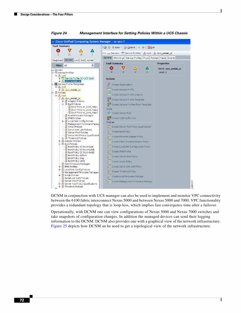
Design Considerations—The Four Pillars
Figure 24 Management Interface for Setting Policies Within a UCS Chassis
DCNM in conjunction with UCS manager can also be used to implement and monitor VPC connectivity between the 6100 fabric interconnect Nexus 5000 and between Nexus 5000 and 7000. VPC functionality provides a redundant topology that is loop-less, which implies fast convergence time after a failover.
Operationally, with DCNM one can view configurations of Nexus 5000 and Nexus 7000 switches and take snapshots of configuration changes. In addition the managed devices can send their logging information to the DCNM. DCNM also provides one with a graphical view of the network infrastructure. Figure 25 depicts how DCNM an be used to get a topological view of the network infrastructure.
72
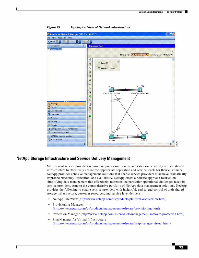
Design Considerations—The Four Pillars
Figure 25 Topological View of Network Infrastructure
NetApp Storage Infrastructure and Service Delivery Management
Multi-tenant service providers require comprehensive control and extensive visibility of their shared infrastructure to effectively ensure the appropriate separation and service levels for their customers. NetApp provides cohesive management solutions that enable service providers to achieve dramatically improved efficiency, utilization, and availability. NetApp offers a holistic approach focused on simplifying data management that effectively addresses the particular operational challenges faced by service providers. Among the comprehensive portfolio of NetApp data management solutions, NetApp provides the following to enable service providers with insightful, end-to-end control of their shared storage infrastructure, customer resources, and service level delivery:
• NetApp FilerView (http://www.netapp.com/us/products/platform-os/filerview.html)
• Provisioning Manager (http://www.netapp.com/us/products/management-software/provisioning.html)
• Protection Manager (http://www.netapp.com/us/products/management-software/protection.html)
• SnapManager for Virtual Infrastructure (http://www.netapp.com/us/products/management-software/snapmanager-virtual.html)
73
Design Considerations—The Four Pillars
• Operations Manager (http://www.netapp.com/us/products/management-software/operations-manager.html)
• SANscreen (http://www.netapp.com/us/products/management-software/sanscreen/sanscreen.html)
NetApp FilerView is the primary, element-level graphical management interface available on every NetApp storage system. NetApp FilerView is an intuitive, browser-based tool that can be used for monitoring and managing administrative tasks on individual NetApp storage systems. In addition to extensive configuration control over storage services, providers can leverage FilerView to assess storage resource capacity and utilization in terms of physical disk aggregates, FlexVol logical volumes, quotas, block storage allocations for SAN attachments, and NFS/CIFS implementation for NAS attachments. NetApp FilerView provides control over administrative and user access to the NetApp storage system. Storage providers can use NetApp FilerView to inspect the health and status of NetApp storage systems, as well as configure notification and alerting services for resource monitoring. While user interfaces like FilerView and the ONTAP command line are instrumental in the provider’s initial build-out of the cloud service architecture, for the subsequent processes involved with the routine service operations, use of these interactive tools should be discouraged in favor of the standards-oriented, policy-driven facilities of NetApp’s management software portfolio.
NetApp Provisioning Manager allows service providers to streamline the deployment of cloud infrastructure and the delivery of tenant storage resources according to established policies. Provisioning Manager enables the cloud administrator to:
• Automate deployment of storage supporting the cloud compute infrastructure as well as the vFiler units and storage delivered to tenant environments.
• Ensure storage deployments conform to provisioning policies defined by the administrators or tenant service level agreements.
• Provision multiprotocol storage with secure separation between tenant environments.
• Automate deduplication and thin provisioning of storage.
• Simplify data migration across the cloud storage infrastructure.
• Delegate control to tenant administrators.
Through the NetApp Management Console, Provisioning Manager delivers dashboard views that display a variety of metrics that can be leveraged to craft policies that further increase resource utilization, operational efficiency, and ensure that storage provisions satisfy the desired levels of capacity, availability, and security. Provisioning policies can be defined within the context of resource pools that are aligned with administrative or tenant requirements. Cloud administrators can delegate Provisioning Manager access and control to tenant administrators within the confines of their separated storage environment, directly extending many of these benefits to their customers.
74
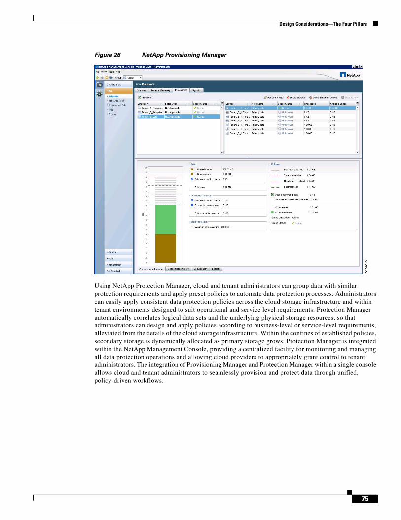
Design Considerations—The Four Pillars
Figure 26 NetApp Provisioning Manager
Using NetApp Protection Manager, cloud and tenant administrators can group data with similar protection requirements and apply preset policies to automate data protection processes. Administrators can easily apply consistent data protection policies across the cloud storage infrastructure and within tenant environments designed to suit operational and service level requirements. Protection Manager automatically correlates logical data sets and the underlying physical storage resources, so that administrators can design and apply policies according to business-level or service-level requirements, alleviated from the details of the cloud storage infrastructure. Within the confines of established policies, secondary storage is dynamically allocated as primary storage grows. Protection Manager is integrated within the NetApp Management Console, providing a centralized facility for monitoring and managing all data protection operations and allowing cloud providers to appropriately grant control to tenant administrators. The integration of Provisioning Manager and Protection Manager within a single console allows cloud and tenant administrators to seamlessly provision and protect data through unified, policy-driven workflows.
75
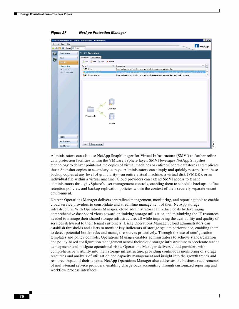
Design Considerations—The Four Pillars
Figure 27 NetApp Protection Manager
Administrators can also use NetApp SnapManager for Virtual Infrastructure (SMVI) to further refine data protection facilities within the VMware vSphere layer. SMVI leverages NetApp Snapshot technology to deliver point-in-time copies of virtual machines or entire vSphere datastores and replicate those Snapshot copies to secondary storage. Administrators can simply and quickly restore from these backup copies at any level of granularity—an entire virtual machine, a virtual disk (VMDK), or an individual file within a virtual machine. Cloud providers can extend SMVI access to tenant administrators through vSphere’s user management controls, enabling them to schedule backups, define retention policies, and backup replication policies within the context of their securely separate tenant environment.
NetApp Operations Manager delivers centralized management, monitoring, and reporting tools to enable cloud service providers to consolidate and streamline management of their NetApp storage infrastructure. With Operations Manager, cloud administrators can reduce costs by leveraging comprehensive dashboard views toward optimizing storage utilization and minimizing the IT resources needed to manage their shared storage infrastructure, all while improving the availability and quality of services delivered to their tenant customers. Using Operations Manager, cloud administrators can establish thresholds and alerts to monitor key indicators of storage system performance, enabling them to detect potential bottlenecks and manage resources proactively. Through the use of configuration templates and policy controls, Operations Manager enables administrators to achieve standardization and policy-based configuration management across their cloud storage infrastructure to accelerate tenant deployments and mitigate operational risks. Operations Manager delivers cloud providers with comprehensive visibility into their storage infrastructure, providing continuous monitoring of storage resources and analysis of utilization and capacity management and insight into the growth trends and resource impact of their tenants. NetApp Operations Manager also addresses the business requirements of multi-tenant service providers, enabling charge-back accounting through customized reporting and workflow process interfaces.
76
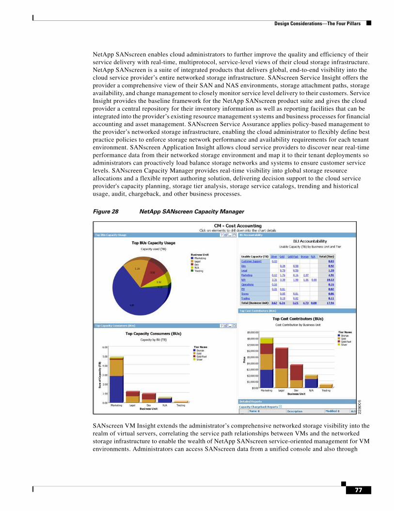
Design Considerations—The Four Pillars
NetApp SANscreen enables cloud administrators to further improve the quality and efficiency of their service delivery with real-time, multiprotocol, service-level views of their cloud storage infrastructure. NetApp SANscreen is a suite of integrated products that delivers global, end-to-end visibility into the cloud service provider’s entire networked storage infrastructure. SANscreen Service Insight offers the provider a comprehensive view of their SAN and NAS environments, storage attachment paths, storage availability, and change management to closely monitor service level delivery to their customers. Service Insight provides the baseline framework for the NetApp SANscreen product suite and gives the cloud provider a central repository for their inventory information as well as reporting facilities that can be integrated into the provider’s existing resource management systems and business processes for financial accounting and asset management. SANscreen Service Assurance applies policy-based management to the provider’s networked storage infrastructure, enabling the cloud administrator to flexibly define best practice policies to enforce storage network performance and availability requirements for each tenant environment. SANscreen Application Insight allows cloud service providers to discover near real-time performance data from their networked storage environment and map it to their tenant deployments so administrators can proactively load balance storage networks and systems to ensure customer service levels. SANscreen Capacity Manager provides real-time visibility into global storage resource allocations and a flexible report authoring solution, delivering decision support to the cloud service provider's capacity planning, storage tier analysis, storage service catalogs, trending and historical usage, audit, chargeback, and other business processes.
Figure 28 NetApp SANscreen Capacity Manager
SANscreen VM Insight extends the administrator’s comprehensive networked storage visibility into the realm of virtual servers, correlating the service path relationships between VMs and the networked storage infrastructure to enable the wealth of NetApp SANscreen service-oriented management for VM environments. Administrators can access SANscreen data from a unified console and also through
77
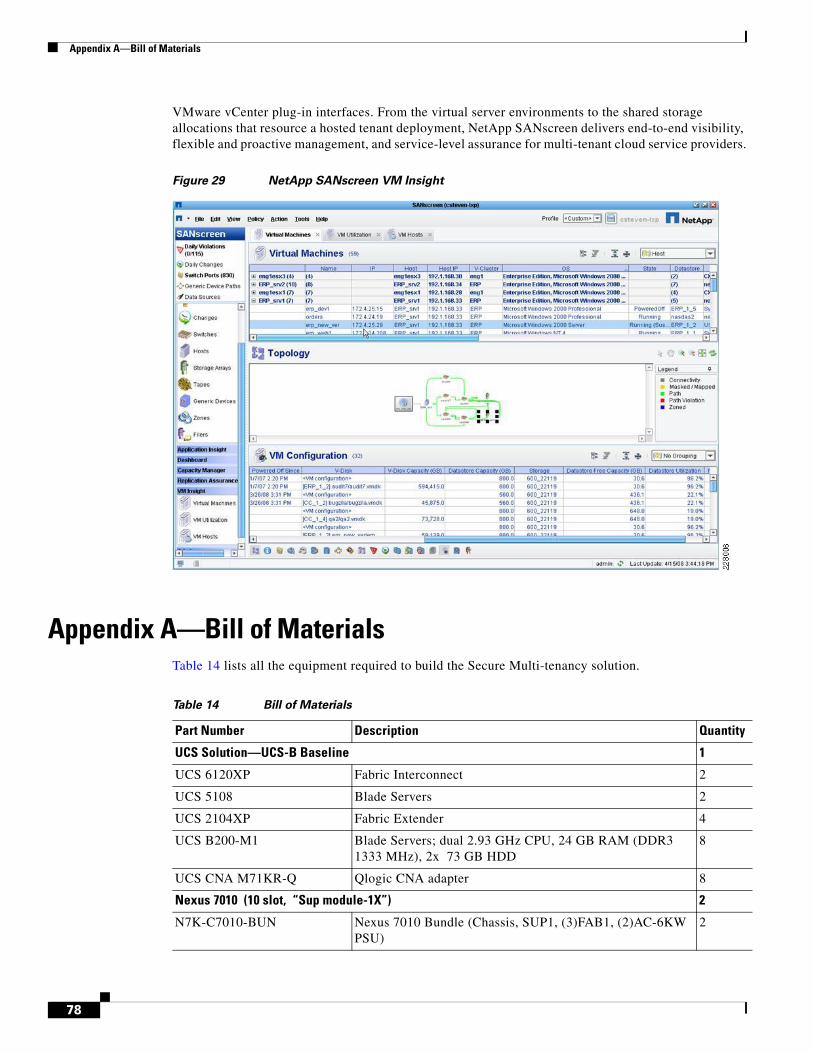
Appendix A—Bill of Materials
VMware vCenter plug-in interfaces. From the virtual server environments to the shared storage allocations that resource a hosted tenant deployment, NetApp SANscreen delivers end-to-end visibility, flexible and proactive management, and service-level assurance for multi-tenant cloud service providers.
Figure 29 NetApp SANscreen VM Insight
Appendix A—Bill of MaterialsTable 14 lists all the equipment required to build the Secure Multi-tenancy solution.
Table 14 Bill of Materials
Part Number Description Quantity
UCS Solution—UCS-B Baseline 1
UCS 6120XP Fabric Interconnect 2
UCS 5108 Blade Servers 2
UCS 2104XP Fabric Extender 4
UCS B200-M1 Blade Servers; dual 2.93 GHz CPU, 24 GB RAM (DDR3 1333 MHz), 2x 73 GB HDD
8
UCS CNA M71KR-Q Qlogic CNA adapter 8
Nexus 7010 (10 slot, “Sup module-1X”) 2
N7K-C7010-BUN Nexus 7010 Bundle (Chassis, SUP1, (3)FAB1, (2)AC-6KW PSU)
2
78
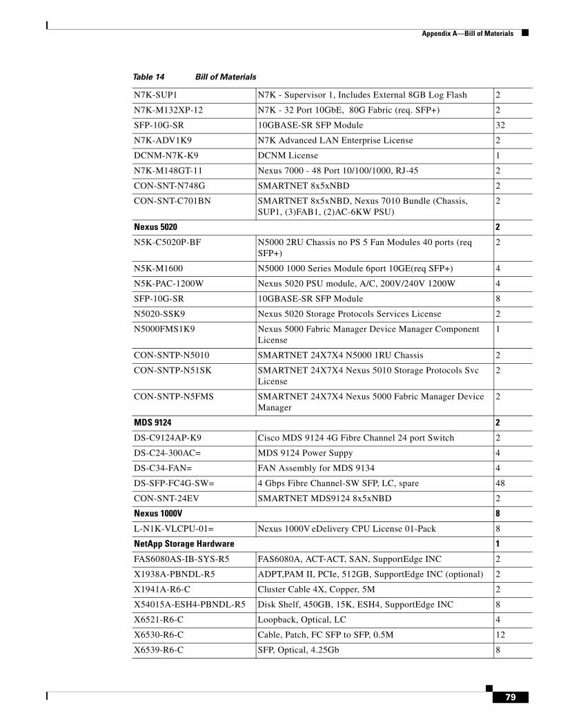
Appendix A—Bill of Materials
N7K-SUP1 N7K - Supervisor 1, Includes External 8GB Log Flash 2
N7K-M132XP-12 N7K - 32 Port 10GbE, 80G Fabric (req. SFP+) 2
SFP-10G-SR 10GBASE-SR SFP Module 32
N7K-ADV1K9 N7K Advanced LAN Enterprise License 2
DCNM-N7K-K9 DCNM License 1
N7K-M148GT-11 Nexus 7000 - 48 Port 10/100/1000, RJ-45 2
CON-SNT-N748G SMARTNET 8x5xNBD 2
CON-SNT-C701BN SMARTNET 8x5xNBD, Nexus 7010 Bundle (Chassis, SUP1, (3)FAB1, (2)AC-6KW PSU)
2
Nexus 5020 2
N5K-C5020P-BF N5000 2RU Chassis no PS 5 Fan Modules 40 ports (req SFP+)
2
N5K-M1600 N5000 1000 Series Module 6port 10GE(req SFP+) 4
N5K-PAC-1200W Nexus 5020 PSU module, A/C, 200V/240V 1200W 4
SFP-10G-SR 10GBASE-SR SFP Module 8
N5020-SSK9 Nexus 5020 Storage Protocols Services License 2
N5000FMS1K9 Nexus 5000 Fabric Manager Device Manager Component License
1
CON-SNTP-N5010 SMARTNET 24X7X4 N5000 1RU Chassis 2
CON-SNTP-N51SK SMARTNET 24X7X4 Nexus 5010 Storage Protocols Svc License
2
CON-SNTP-N5FMS SMARTNET 24X7X4 Nexus 5000 Fabric Manager Device Manager
2
MDS 9124 2
DS-C9124AP-K9 Cisco MDS 9124 4G Fibre Channel 24 port Switch 2
DS-C24-300AC= MDS 9124 Power Suppy 4
DS-C34-FAN= FAN Assembly for MDS 9134 4
DS-SFP-FC4G-SW= 4 Gbps Fibre Channel-SW SFP, LC, spare 48
CON-SNT-24EV SMARTNET MDS9124 8x5xNBD 2
Nexus 1000V 8
L-N1K-VLCPU-01= Nexus 1000V eDelivery CPU License 01-Pack 8
NetApp Storage Hardware 1
FAS6080AS-IB-SYS-R5 FAS6080A, ACT-ACT, SAN, SupportEdge INC 2
X1938A-PBNDL-R5 ADPT,PAM II, PCIe, 512GB, SupportEdge INC (optional) 2
X1941A-R6-C Cluster Cable 4X, Copper, 5M 2
X54015A-ESH4-PBNDL-R5 Disk Shelf, 450GB, 15K, ESH4, SupportEdge INC 8
X6521-R6-C Loopback, Optical, LC 4
X6530-R6-C Cable, Patch, FC SFP to SFP, 0.5M 12
X6539-R6-C SFP, Optical, 4.25Gb 8
Table 14 Bill of Materials
79

Appendix A—Bill of Materials
NetApp provides no representations or warranties regarding the accuracy, reliability or serviceability of any information or recommendations provided in this publication, or with respect to any results that may be obtained by the use of the information or observance of any recommendations provided herein. The information in this document is distributed AS IS, and the use of this information or the implementation of any recommendations or techniques herein is a customer's responsibility and depends on the
X6553-R6-C Optical Cable, 50u, 2GHz/KM, MM, LC/LC, 2M 12
X1107A-R6 2pt, 10GbE NIC, BareCage SFP+ Style, PCIe 4
X-SFP-H10GB-CU5M-R6 Cisco N50XX 10GBase Copper SFP+ cable, 5m 4
X6536-R6 Optical Cable, 50u, 2000MHz/Km/MM, LC/LC, 5M 8
X6539-R6 Optical SFP, 4.25Gb 8
CS-O-4HR SupportEdge Premium, 7x24, 4hr Onsite – 36 months 1
NetApp Storage Software
SW-T7C-ASIS-C A-SIS Deduplication Software 2
SW-T7C-CIFS-C CIFS Software 2
SW-T7C-NFS-C NFS Software 2
SW-T7C-FLEXCLN-C Flexclone Software 2
SW-T7C-MSTORE-C MultiStore Software 2
SW-T7C-NEARSTORE-C Nearstore Software 2
SW-T7C-PAMII-C PAM II Software (required only if PAM is purchased) 2
SW-T7C-SANSCREEN SANscreen Software
SW-T7C-SMSVS-C SnapMirror SnapVault Software Bundle 2
SW-T7C-SMVI-VMWARE-C SnapManager for VI SW 2
SW-T7C-SRESTORE-C SnapRestore Software 2
SW-T7C-DFM-OPSMGR Operations Manager 2
SW-T7C-DFM-PROTMGR Protection Manager 2
SW-T7C-DFM-PROVMGR Provisioning Manager 2
SW-SSP-T7C-OPSMGR SW Subs, Operations Manager – 25 months 2
SW-SSP-T7C-PROTMGR SW Subs, Protection Manager – 25 months 2
SW-SSP-T7C-PROVMGR SW Subs, Provisioning Manager – 25 months 2
Virtualization Software
VS4-ENT-PL-C VMware vSphere 4 Enterprise Plus 2
VCS-STD-C VMware vCenter Server Standard 1
VCHB-VCMS55-C VMware vCenter Server Heartbeat 1
Virtualization SnS (Minimum of one year SnS is required for all virtualization software)
VS4-ENT-PL-P-SSS-C VMware vSphere 4 SnS 1
VCS-STD-P-SSS-C VMware vCenter Sns 1
VCHB-VCMS-P-SSS-C VMware vCenter Server Heartbeat SnS 1
Table 14 Bill of Materials
80

Appendix A—Bill of Materials
customer's ability to evaluate and integrate them into the customer's operational environment. This document and the information contained herein must be used solely in connection with the NetApp products discussed in this document.
81
Appendix A—Bill of Materials
82