designing porous antifouling interfaces for high‐power
TRANSCRIPT
www.afm-journal.de
© 2021 Wiley-VCH GmbH2107160 (1 of 9)
1. Introduction
The rapid development of implantable electronics opens up various promising applications in biomedicine such as real-time health monitoring, disease diagnosis, and treatment.[1–7]
ReseaRch aRticle
Designing Porous Antifouling Interfaces for High-Power Implantable Biofuel CellLie Wang, Er He, Rui Gao, Xiaotong Wu, Anwei Zhou, Jiang Lu, Tiancheng Zhao, Jiaxin Li, Yanjing Yun, Luhe Li, Tingting Ye, Yiding Jiao, Jiacheng Wang, Hao Chen, Dan Li, Xinghai Ning, Di Wu, Huisheng Peng,* and Ye Zhang*
Biofuel cells that can convert the chemical energy of biomass such as glucose into electricity are expected to continuously obtain energy from living organisms and solve bottlenecks of energy supply for implanted electronics. However, the use of biofuel cells is limited mainly by the sharp drop in performance after implanting in living organisms caused by biofouling and electrode surface inactivation. Herein, a simple and effective strategy to overcome these problems by designing a porous antifouling interface on biofuel cells, is demonstrated. It resists the biofouling from body fluid while sustaining reactant penetration, and also enhances immobilization of enzymes. As a result, the biofuel cell can maintain almost 100% performance after implanting in living organisms, and a maximal output power of 76.6 mW cm-3 is achieved in vivo, which is ≈96 times of the highest performance reported to date. This strategy is universal and can be extended to the other electronic devices such as electrochemical sensors, which presents a new avenue for developing high-performance implanted electronics.
DOI: 10.1002/adfm.202107160
L. Wang, E. He, R. Gao, X. Wu, A. Zhou, J. Lu, Y. Yun, L. Li, T. Ye, Y. Jiao, J. Wang, H. Chen, X. Ning, D. Wu, Y. ZhangNational Laboratory of Solid State MicrostructuresJiangsu Key Laboratory of Artificial Functional MaterialsChemistry and Biomedicine Innovation Center (ChemBIC)Collaborative Innovation Center of Advanced MicrostructuresCollege of Engineering and Applied SciencesNanjing UniversityNanjing 210023, ChinaE-mail: [email protected]. Zhao, J. Li, H. PengState Key Laboratory of Molecular Engineering of PolymersDepartment of Macromolecular Science and Laboratory of Advanced MaterialsFudan UniversityShanghai 200438, ChinaE-mail: [email protected]. LiDepartment of immunologyNanjing University of Chinese MedicineNanjing 210046, China
To this end, it is urgent to develop an alternative power device for implant-able electronics.[8–10] Biofuel cell (BFC) is recognized to generate electricity using enzymes as bioelectrocatalysis.[11–15] It can convert chemical energy into electrical energy by oxidizing and reducing bio-fuels in body fluids, which are expected to continuously harvest energy from living organisms and be considered as a prom-ising implantable power device.[16,17]
Recently, some attempts have been made to develop implantable BFCs and achieve energy harvesting in organisms such as snail, clam, cockroach, rat, and rabbit.[18–22] However, the performance of most BFCs operated in vivo was much lower than that tested in vitro, which seri-ously hindered its implantable applica-
tions.[23–25] The main reason lies in that cells and proteins from body fluids were readily adsorbed/adhered on/to the electrode surface to form biofouling layers, which impeded bioelectrocat-alytic reactions (Figure 1a).[26–28] Meanwhile, the dynamic flow of body fluid also accelerated the shedding of enzymes from electrodes, leading to rapid degradation in performance.[29] To the best of our knowledge, the maximal output power of reported implantable BFCs is only several hundred microwatts per milliliter (Table S1, Supporting Information).
Herein, we have overcome these problems by designing a porous antifouling interface (PAI) to fabricate a novel implantable BFC (denoted as BFC–PAI). The PAI not only resisted the biofouling from body fluid but sustained reactant penetration; it also improved immobilization of enzymes to further enhance the overall bioelectrocatalytic performance (Figure 1b). As a result, the BFC–PAI can maintain almost 100% performance after implanting in living organisms, and a maximal output power of 76.6 mW cm–3 was achieved in vivo, which was ≈96 times of the highest performance reported to date.
2. Results and Discussion
2.1. Fabrication of the BFC–PAI
Figure S1, Supporting Information, schematically illustrates the fabrication and structure of the BFC–PAI. Bioanode and biocathode were fabricated by electrochemically depositing
The ORCID identification number(s) for the author(s) of this article can be found under https://doi.org/10.1002/adfm.202107160.
Adv. Funct. Mater. 2021, 2107160

www.afm-journal.dewww.advancedsciencenews.com
2107160 (2 of 9) © 2021 Wiley-VCH GmbH
a layer of functional materials of 2-aminoanthracene and polyethylene blue onto carbon nanotube (CNT) fibers, respec-tively. The CNT fiber (Figure S2, Supporting Information) was prepared via floating catalyst chemical vapor deposition and simultaneously showed high mechanical, electrical, and elec-trochemical properties (Figures S3–S5, Supporting Informa-tion).[30] A layer of PAI precursor was then coated onto the CNT fibers, followed by exposure to UV irradiation (λ = 365 nm) for ≈10 min to form a solidified enzymes/polymer composite matrix. The precursor was mixed with enzyme, hydroxy-rich polymer polyvinyl alcohol (PVA), and cationic polymer poly(vinyl alcohol)-N-methyl-4(4′-formylstyryl) pyridinium-methosulfateacetal (PVA-SbQ). Flavin adenine dinucleotide-dependent glucose dehydrogenase (FADGDH) and bilirubin oxidase (BOx) were used as bioelectrocatalysis for oxidizing glucose and reducing O2, respectively. The BFC–PAI was finally produced by assembling the bioanode and biocathode together with a two-ply fiber configuration (Figure S6, Sup-porting Information).
2.2. Characterization of the BFC–PAI
Figure 2a–d shows typical scanning electron microscopy (SEM) and atomic force microscopy (AFM) images of the PAI on biocathode and bioanode. It indicated a 3D porous structure with typical micropores of 1–2 µm (Figure S7, Sup-porting Information). Furthermore, nitrogen adsorption isotherms showed that PAI was composed of nanopores with an average pore size of 38 nm (Figure S8, Supporting Information). Therefore, PAI can offer highly efficient dif-fusion of reacting substances. The formation mechanism of 3D porous structure may be explained by the structural interactions between negatively charged amino acid chains of enzyme and positively charged styryl pyridinium side chains in PVA–SbQ, which can be further cross-linked via a photo-stimulated cycloaddition reaction.[31,32] In this process, the polymer matrix can not only physically entrap the enzymes on the electrode but also improve their immobilization via elec-
trostatic interactions between negatively charged amino acid chains of enzymes and positively charged styrylpyridinium side chains in PVA–SbQ.[33,34] Fluorescence microscopy and SEM characterizations demonstrated that the shedding of the enzyme from the electrode was remarkably reduced after rinsing (Figure 2e,f; Figures S9 and S10, Supporting Informa-tion). Based on the above advantages, the bioelectrocatalytic performance of both O2 reduction and glucose oxidization can be effectively enhanced. As shown in Figure 2g–i, when it was tested in 5 mm glucose/phosphate buffer saline (PBS) solu-tion, both reaction currents of biocathode and bioanode fabri-cated with PAI were larger than those without PAI.
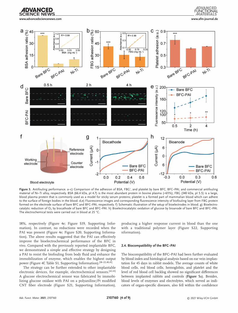
The antifouling performance of the BFC–PAI was also eval-uated. As shown in Figure 3a,b; Table S1, Supporting Informa-tion, the BFC–PAI exhibited less than 7% and 30% adhesion ratios to bovine serum albumin (BSA) and fibrinogen (FBG) proteins in the blood, which are comparable to the excellent antifouling materials such as Ni–Ti alloy, that is, 10% and 28%, respectively. As a comparison, the adhesion rates of the bare BFC for BSA and FBG proteins were as high as 37% and 43%, respectively. The platelet adhesion was also tested with a similar phenomenon (Figure 3c; Table S2, Supporting Infor-mation). Moreover, fluorescence microscopy images were used to visualize the biofouling layer on the BFC–PAI. As shown in Figures 3d,e; Table S3, Supporting Information, the fibrin deposition and network formation were more remark-able on the bare BFC than the BFC–PAI, suggesting that the PAI can efficiently prevent the biofouling phenomenon from body fluid. The high antifouling performance could be attrib-uted to the abundant hydroxyl groups on the polymer back-bone (Figures S11 and S12, Supporting Information), which can interact with water molecules to form a hydration shell to resist the adsorption/adhesion of cells and proteins.[35–39] Although the traditional antifouling layer such as PVA on BFC showed the similar antifouling performance to BFC–PAI (Figure S13, Supporting Information), the low immobilization ability to enzymes (Figures S14 and S15, Supporting Informa-tion) and the formation of dense barrier hindered reactant penetration and electron connection (Figure S16, Supporting
Figure 1. Schematic illustration of BFC operated in body fluids. a) Bare BFC operated in living organisms shows a sharp drop of performance due to the formation of biofouling and shedding of the enzyme. b) Our strategy by designing a PAI on BFC with combined porous structure, high enzyme immobilization ability, and good antifouling performance remarkably enhances the overall bioelectrocatalytic performance.
Adv. Funct. Mater. 2021, 2107160

www.afm-journal.dewww.advancedsciencenews.com
2107160 (3 of 9) © 2021 Wiley-VCH GmbH
Information), resulting in decreasing catalytic current densi-ties (Figure S17, Supporting Information). Therefore, the com-bination of porous structure, high enzyme immobilization ability, and good antifouling performance of the PAI endows high bioelectrocatalytic properties of bioelectrodes operated in blood (Figure 3f–h).
2.3. Electrochemical Performance of the BFC–PAI in Body Fluids
The performance of a complete BFC–PAI was then tested in blood in vitro. A maximal power density of 60.1 mW cm−3 was achieved with an open circuit voltage of 0.59 V (Figure 4a). The stability of the BFC–PAI was also tested by recording the output voltage with a pulse discharge current density of 40 mA cm−3 every 60 s. After operating for 2 h, the discharge voltage was
maintained by ≈90%, demonstrating a high stability (Figure 4b). In comparison, when the BFC was fabricated without PAI, it only delivered a maximal power density of 15 mW cm−3 with an open circuit voltage of 0.52 V (Figure 4a), and the output voltage had been decreased remarkably after operating for 2 h (Figure 4b).
To evaluate the electrochemical performance tested in blood in vivo, the BFC–PAI was further implanted into the ear vein of a rabbit through a minimally invasive syringe-assisted method (Figure 4c; and Figure S18, Supporting Information). After implantation, a maximal power density of 76.6 mW cm−3 was obtained with an open circuit voltage of 0.61 V (Figure 4d). Moreover, the change of electrochemical performance of the BFC was also compared when operated from PBS solution to blood. When the PAI was absent, the maximal power density and open circuit voltage of the BFC were reduced by 60% and
Figure 2. Porous structure and enzyme immobilization ability. a,b) SEM images of PAI on bioanode and biocathode, respectively. Scale bar, 10 µm. c,d) AFM images of PAI on bioanode and biocathode, respectively. Scale bar, 5 µm. e,f) Fluorescence images and corresponding fluorescence intensity of enzyme immobilization on the electrode with or without PAI before and after rinsing with PBS solution, respectively. Scale bar, 50 µm. g) Schematic illustration of the setup of bioelectrodes in PBS solution. h) Bioelectrocatalytic reduction of O2 by biocathode of bare BFC and BFC–PAI. i) Bioelectro-catalytic oxidation of glucose by bioanode of bare BFC and BFC–PAI. The electrochemical tests were carried out in 0.1 m PBS solution (pH 7.4) with 5 mm glucose at 25 °C.
Adv. Funct. Mater. 2021, 2107160
www.afm-journal.dewww.advancedsciencenews.com
2107160 (4 of 9) © 2021 Wiley-VCH GmbH
18%, respectively (Figure 4e; Figure S19, Supporting Infor-mation). In contrast, no reductions were recorded when the PAI was present (Figure 4e; Figure S20, Supporting Informa-tion). The above results suggested that the PAI can effectively improve the bioelectrochemical performance of the BFC in vivo. Compared with the previously reported implantable BFC, we demonstrated a simple and effective strategy by designing a PAI to resist the biofouling from body fluid and enhance the immobilization of enzyme, which enables the highest output power (Figure 4f; Table S1, Supporting Information).[18–22,40,41]
The strategy can be further extended to other implantable electronic devices, for example, electrochemical sensors.[42,43] A glucose electrochemical sensor was fabricated by immobi-lizing glucose oxidase with PAI on a polyaniline/Pt modified CNT fiber electrode (Figure S21, Supporting Information),
producing a higher response current in blood than the one with a traditional polymer layer (Figure S22, Supporting nformation).
2.4. Biocompatibility of the BFC–PAI
The biocompatibility of the BFC–PAI had been further evaluated by blood index and histological analysis based on ear vein implan-tation for 45 days in rabbit models. The average counts of white blood cells, red blood cells, hemoglobin, and platelet and the level of red blood cell backlog showed no significant differences between implanted rabbits and controls (Figure 5a). Besides, blood levels of enzymes and electrolytes, which served as indi-cators of organ-specific diseases, also fell within the confidence
Figure 3. Antifouling performance. a–c) Comparison of the adhesion of BSA, FBG’, and platelet by bare BFC, BFC–PAI, and commercial antifouling material of Ni–Ti alloy, respectively. BSA (66.4 kDa, pI 4.7) is the most abundant protein in bovine plasma (≈65%); FBG (340 kDa, pI 5.5) is a large, blood plasma protein that is commonly used as a model for sticky serum proteins; platelet is a formed part of mammalian blood which can adhere to the surface of foreign bodies in the blood. d,e) Fluorescence images and corresponding fluorescence intensity of biofouling layer from FBG protein formed on the electrode surface of bare BFC and BFC–PAI, respectively. f) Schematic illustration of the setup of bioelectrodes in blood. g) Bioelectro-catalytic reduction of O2 by biocathode of bare BFC and BFC–PAI. h) Bioelectrocatalytic oxidation of glucose by bioanode of bare BFC and BFC–PAI. The electrochemical tests were carried out in blood at 25 °C.
Adv. Funct. Mater. 2021, 2107160

www.afm-journal.dewww.advancedsciencenews.com
2107160 (5 of 9) © 2021 Wiley-VCH GmbH
intervals of control values (Figure 5b). Moreover, hematoxylin and eosin (H&E) staining showed that the tissue around the BFC–PAI was similar to the controls, suggesting good integra-tion between the device and tissue (Figure 5c; Figure S23, Sup-porting Information). The H&E stained tissue slices of the major organs, for example, heart, liver, spleen, lung, and kidney, were also analyzed (Figure 5d). No noticeable pathological change was observed, indicating that the BFC–PAI had no evident systemic side effects on the rabbit. It can be further verified by the fact that the weight changes of rabbits implanted with BFC–PAI were similar to the controls (Figure S24, Supporting Information). Moreover, the endothelial cells and macrophage densities were studied by immunofluorescence staining of various markers (CD 31 and F4/80), and no significant differences were found between the tissues with the BFC–PAI and the control group without implants (Figure 5e,f). These combined results indicated that the BFC–PAI owned high biocompatibility, mainly due to
the low biotoxicity (Figures S25 and S26, Tables S5 and S6, Sup-porting Information) and soft fiber configuration of devices that can realize stable interfaces with tissues.[44]
3. Conclusion
In summary, we have demonstrated a simple and effective strategy to improve the performance of BFC in vivo by designing an enzyme/polymer composite matrix that combined porous struc-ture, high enzyme immobilization ability, and good antifouling performance. The resulting implantable BFC can maintain almost 100% performance after implanting in living organisms, and a max-imal output power of 76.6 mW cm−3 was achieved in vivo, which was ≈96 times of the highest performance reported to date. This work may open up a new direction in developing high-performance implanted electronic devices for biomedical applications.
Figure 4. Electrochemical performance in body fluids. a) Polarization curves and power density curves of bare BFC and BFC–PAI operated in blood in vitro. b) Stability of bare BFC and BFC–PAI operated in blood in vitro by recording the output voltage with a pulse discharge current density of 40 mA cm–3 every 60 s. c) Schematic illustration (top left) and whole (top right) and enlarged (below) optical images of the BFC–PAI implanted into the ear vein of a rabbit. d) Polarization curve and power density curve of BFC–PAI operated in blood in vivo. e) Comparison of the change of power density and open circuit voltage (labeled as OCV) of bare BFC and BFC–PAI operated from PBS solution to blood. f) The power density of the BFC–PAI operated in vivo compared with the previous implantable BFC with traditional immobilized material coatings, for example, glycidyl (GL), BSA, chitosan (CS), poly (ethylene glycol) diglycidyl ether (PD), and glutaraldehyde (GA) or without coating (labeled as None).
Adv. Funct. Mater. 2021, 2107160

www.afm-journal.dewww.advancedsciencenews.com
2107160 (6 of 9) © 2021 Wiley-VCH GmbH
4. Experimental SectionMaterials: Polyvinyl alcohol (PVA, 1750 ± 50) and pig blood (EDTA
anticoagulation) were purchased from Shanghai Yuanye Biological Technology Co., Ltd. Poly(vinyl alcohol)-N-methyl-4(4′-formylstyryl) pyridiniummethosulfateacetal (PVA-SbQ, 168-H) was purchased from Shanghai Guangyi Printing Equipment Technology Co., Ltd. Methylene blue (MB, 82%), bilirubin oxidase from Myrothecium verrucaria (BOx, 15–65 U mg−1), glucose oxidase from Aspergillus niger (GOx, 30 U mg−1), and Nafion (5 wt% in a mixture of lower aliphatic alcohols and water) were obtained from Sigma–Aldrich. Phosphate buffer saline
instant dissolving granules (pH 7.4), KNO3 (99%), NaNO2 (99.99%), ethanol (99.7%), KCl (99.5%), and NaCl (99.5%) were provided by Sinopharm Chemical Reagent Co., Ltd. Flavin adenine dinucleotide–glucose dehydrogenase (FADGDH, 200 U mg−1) was purchased from Shanghai Ruiyong Biological Technology Co., Ltd. 2-aminoanthracene (2-ANT, 94%) was obtained from Alfa Aesar. HCl (99%) and H2SO4 (98%) were purchased from Nanjing Chemical Reagent Co., Ltd. Polydimethylsiloxane (Sylgard 184) was purchased from Dow Corning. Tris(hydroxymethyl)aminomethane hydrochloride (TRIS, 99%), aniline (99.5%), K2PtCl6 (98%), pyruvate (96%), paraformaldehyde (99.7%), and rhodamine B (99%) were purchased from Shanghai Aladdin Biochemical
Figure 5. Biocompatibility. a) The change of average counts of white blood cell (WBC), red blood cell (RBC), hemoglobin (HGB), platelet (PLT), and hematocrit (HCT) after implantation for 45 days. b) The change of blood levels of aspartate transaminase (AST), alaninetransaminase (ALT), alkaline phosphatase (ALP), total bile acid (TBA), total bilirubin (TBIL), blood urea nitrogen (BUN), and creatinine (CREA) after implantation for 45 days. c) Representative H&E stained sections of the blood vessel with implanted BFC–PAI for 45 days and non-implanted controls. Scale bar, 50 µm. d) Histological data (representative H&E stained sections) were obtained from the major organs, including the heart, liver, spleen, lung, and kidney of rabbit with and without implanted BFC–PAI for 45 days. Scale bar, 50 µm. e, f) Visualization of inflammation (orange fluorescence) and blood vessels (red fluorescence) by immune-staining with macrophage cell marker F4/80 and endothelial cell marker CD31, in ear tissues with or without implanta-tion for 45 days, respectively. The nucleus is shown in blue. Scale bar, 100 µm.
Adv. Funct. Mater. 2021, 2107160
www.afm-journal.dewww.advancedsciencenews.com
2107160 (7 of 9) © 2021 Wiley-VCH GmbH
Technology Co. Ltd. Single-walled carbon nanotube (SWCNT, 10–20 nm in diameter) was purchased from XFNANO Material Technology Co., Ltd. Triton X-100 (99%), β-Nicotinamide adenine dinucleotide disodium salt, bovine serum albumin (BSA, 20 mg mL–1), human fibrinogen (FBG), and goat anti-human fibrinogen/fluorescein isothiocyanate (FITC) were purchased from Nantong Feiyu Biological Technology Co., Ltd. Bicinchoninic acid (BCA) protein concentration determination kit was purchased from Beyotime Biotechnology Technology Co., Ltd.
Preparation of the Bioelectrode and BFC–PAI: Preparation of the PAI Precursor Solution: PVA (0.05 g) was first dissolved in 10 mL of deionized water under magnetic stirring at 97 °C for 1.5 h to form a homogeneous solution. A mixed solution with 0.7 mL PVA, 0.3 mL PVA–SbQ, and 0.1 mL enzyme (300 U mL–1 for FADGDH and 38 U mL–1 BOx) was then stirred at room temperature for 2 h to obtain FADGDH-based PAI and BOx based PAI precursor solution, respectively.
Preparation of the Biocathode: The preparation of the biocathode is schematically shown in Figure S1a, Supporting Information. A thin layer of polydimethylsiloxane (PDMS) was first coated on one-half of a CNT fiber to serve as the insulating layer. Then, the other-half of the CNT fiber was modified with 2-ANT through a cyclic voltammetry method: (i) the CNT fiber, Pt, and Ag/AgCl were used as working, counter, and reference electrodes, respectively; (ii) 1 mm 2-ANT and 5 mm NaNO2 dissolved in 0.5 mm ice-cold HCl–ethanol (50% v/v) solution to form the 2-ANT diazonium cation solution; (iii) the CNT fiber was immersed into the solution and purged with Ar for 20 min to remove O2. By sweeping from −1 to 1 V for two cycles at a scan rate of 100 mV s–1, the aryl diazonium cation was electrochemically reduced on the CNT fiber. After that, 15 µL of BOx based PAI precursor solution was dipped onto the CNT/2-ANT fiber, followed by photopolymerizing under a UV lamp (λ = 365 nm, 10 min) at room temperature. Finally, the biocathode was obtained by gently washing the biocathode with PBS solution and drying overnight at 4 °C.
Preparation of the Bioanode: The preparation of the bioanode is schematically shown in Figure S1b, Supporting Information. The CNT fiber was first modified with polymethylene blue (PMB) by a cyclic voltammetry method: (i) the CNT fiber, Pt, and Ag/AgCl were used as working, counter, and reference electrodes, respectively; (ii) the CNT fiber was immersed into a mixed borate buffer solution (0.02 m, pH 9.12) consisting of 0.25 mm MB and 0.1 m KNO3 by sweeping from −0.4 to 1.2 V for 50 cycles at a scan rate of 50 mV s–1. iii) 15 µL of FADGDH based PAI precursor solution was dipped onto the CNT/PMB fiber, followed by photopolymerizing under a UV lamp (λ = 365 nm, 10 min) at room temperature. Finally, the bioanode was obtained by gently washing it with PBS solution and drying overnight at 4 °C.
Assembly of the BFC–PAI: The structure of the BFC–PAI is schematically shown in Figure S1c, Supporting Information. The insulated part of the as-prepared biocathode was twisted with the as-prepared bioanode to form a complete BFC–PAI. The twisting process was carried out by a motor at a speed of 200 rpm.
Antifouling Performance: Platelet Adhesion Assay: Platelet-rich plasma was obtained by centrifuging fresh blood at 1000 rpm for 15 min. Sample (surface area of ≈0.05 mm2) in triplicates was immersed with 100 µL platelet-rich plasma in a 96-well plate and incubated for 4 h at 37 °C. The samples were gently rinsed with PBS solution three times and added with 40 µL Triton X-100 (1% v/v) to lyse platelets. After 5 min, platelet lysates were poured on Eppendorf tubes and centrifuged for 5 min at a speed of 1500 rpm. Then, the supernatant was placed in a 96-well plate and added with 200 µL TRIS buffer (containing 3.33 mg mL−1 β-Nicotinamide adenine dinucleotide disodium salt and 3.33 mg mL–1 pyruvate, pH 6.8–7.2). Finally, the samples were analyzed using a UV–vis spectrophotometer (TECAN, infinite M200 PRO) at the wavelength of 340 nm. The tests were repeated at least three times. Statistical significance was calculated using unpaired Student’s t-test. * represents p < 0.05, ** represents p < 0.01, and *** represents p < 0.001.
Protein Adsorption Evaluated by BCA Assay: First, BSA or FBG protein powder (20 mg) was dissolved in 0.8 mL NaCl solution (0.9 wt%) at 37 °C under gently shaking to form a homogeneous standard protein solution. Concentration-gradient solutions (0, 0.025, 0.05, 0.1, 0.2, 0.3,
0.4, and 0.5 mg mL–1) were then obtained by adding the protein solution to NaCl solution. Secondly, the wells of a 96-well plate consisted of 20 µL standard protein solution and 200 µL BCA-A : BCA-B (50:1 v/v) solution and incubated for 4 h at 37°C. The samples were analyzed using a UV–vis spectrophotometer (TECAN, infinite M200 PRO) at the wavelength of 562 nm, and a standard curve was obtained by setting the content of protein as the abscissa and absorbance as the ordinate. Third, samples (surface area of ≈0.05 mm2) in triplicates were immersed with 100 µL 0.5 mg mL–1 BSA or FBG solution in a 96-well plate and incubated for 4 h at 37 °C. Afterward, 20 µL of each well’s solution was poured into another 96-well plate to measure the absorbance according to the second step. Finally, the protein adsorption on each sample was calculated by contrasting the results with the standard curve. The protein adsorption ratio was calculated by:
( ) = −Protein adsorptionratio % 0.50.5
C (1)
Where C was the concentration of the sample group; the tests were repeated at least three times. Statistical significance was calculated using unpaired Student’s t-test. * represents p < 0.05, ** represents p < 0.01, and *** represents p < 0.001.
Fibrin Deposition Assay: The samples (the surface area is ≈0.05 mm2) were placed in the wells of a 96-well plate with 100 µL FBG solution (0.9 wt% NaCl solution, 0.5 mg mL–1) and incubated for 4 h at 37 °C. After gently rinsing with 0.9 wt% NaCl solution, the wells with samples were blocked with 100 µL BSA solution (0.9 wt% NaCl solution, 1 wt%) for 30 min at 37 °C and rinsed with 0.9 wt% NaCl solution. Next, the wells with samples were added with Goat anti-human fibrinogen/FITC and incubated for increasing time points at 37 °C. After removing from wells, the samples were gently rinsed with 0.9 wt% NaCl solution and fixed on a glass slide. Then, the samples were imaged with an inverted fluorescence microscope (Axio Vert A1 FL-LED). Finally, the images were analyzed and quantified with Image J. The tests were repeated at least three times. Statistical significance was calculated using unpaired Student’s t-test. * represents p < 0.05, ** represents p < 0.01, and *** represents p < 0.001.
Electrochemical Test In Vitro: The electrochemical test in vitro was carried out in 30 mL of 5 mm glucose/PBS solution or blood using an electrochemical workstation (CorrTest CS350). For biocathode and bioanode, a three-electrode system was used with the biocathode or bioanode as working electrode, commercial Pt electrode as counter electrode, and Ag/AgCl electrode as reference electrode. For BFC, a two-electrode system with assembled biocathode and bioanode together was studied. The polarization curves were recorded using linear sweep voltammetry in potentiostatic mode at a scan rate of 0.5 mV s−1. Electrochemical impendence analysis of different electrodes was tested in AC impedance parameters with a frequency range of 0.1–100 000 Hz. The tests were repeated at least three times.
Electrochemical Test In Vivo: Animal Preparation: The experiment protocols were approved by the Animal Experimentation Committee of the Nanjing University of Chinese Medicine. All animals were treated following guidelines for the care and use of experimental animals described by the National Institutes of Health and Nanjing University of Chinese Medicine. Eight adult rabbits (≈1.5–2.5 kg in weight) were purchased from Nanjing Qinglongshan Animal Breeding Farm. Weights of the rabbits were recorded every day.
Implantation of the BFC–PAI and Test In Vivo: First, the BFC–PAI was threaded into the 5-mL-syringe pre-filled with normal saline. The reaction area of the device was kept in the needle and the other parts were left in the syringe body. Then, the hair over the ears was removed by depilatory cream and the skin was cleaned with iodophor and 75% (v/v) alcohol. Sodium pentobarbital (2 mL, 50 mg mL−1) was injected into the ear vein to keep the rabbits anesthetized during the experiment. After that, the BFC was injected into another ear vein by intravenous injection along with the solution flowing. Finally, the needle was retreated from the vein, and bleeding was stanched by compression of a cotton ball. The electrochemical test in vivo was carried out with a two-electrode system
Adv. Funct. Mater. 2021, 2107160
www.afm-journal.dewww.advancedsciencenews.com
2107160 (8 of 9) © 2021 Wiley-VCH GmbH
using an electrochemical workstation (CorrTest CS350). The polarization curves were recorded using linear sweep voltammetry in potentiostatic mode at a scan rate of 0.5 mV s−1. The tests were repeated at least three times.
Biocompatible Studies: Blood Hemolysis: Each sample (surface area of ≈0.05 mm2) was incubated in 500 µL pig blood (EDTA anticoagulation) for 0.5 h at 37 °C. Next, 4 mL of 0.9 wt% NaCl solution was added to each sample. Then, the samples were further incubated for 4 h at 37°C. Two controls were used as received blood (0.9 wt% NaCl solution added) and lysed blood (deionized water added). After that, the blood was poured on Eppendorf tubes and centrifuged for 10 min at a speed of 1500 rpm. The supernatant was placed in a 96-well plate (Corning) and analyzed using a UV–vis spectrophotometer (TECAN, infinite M200 PRO) at the wavelength of 540 nm, which corresponded to the maximum absorbance for oxygenated hemoglobin. Three parallel samples (n = 3) were laid in each group. The mean value of the optical densities (OD) was obtained as the group value. Finally, the hemolysis ratio was calculated by:
Hemolysis ratio % s np n
D DD D( ) = −
− (2)
Where Ds, Dn, and Dp were the OD values of the sample group, negative reference, and positive reference, respectively. The tests were repeated at least three times. Statistical significance was calculated using unpaired Student’s t-test. * represents p < 0.05, ** represents p < 0.01, and *** represents p < 0.001.
Hematology and Blood Chemistry: After the BFC–PAI was implanted in rabbits for 0, 3, 15, and 45 days, the blood samples were collected for hematology and blood chemistry examination. Hematology of the blood samples was tested by an automatic blood cell analyzer for animal use (Mairui, BC-2800vet). Blood chemistry examinations were tested according to alanine substrate method (alanine aminotransferase, ALP), aspartic acid substrate method (aspartic acid aminotransferase, AST), NPP substrate-AMP buffer method (Alkaline phosphatase, ALP), V generation cyclic enzymatic method (total bile acid, TBA), urease-glutamate dehydrogenase method (UREA), and enzymatic analysis (creatinine, CREA). The tests were repeated at least three times.
Histology and Immunohistochemistry: Euthanasia of rabbits was done on Day 45 after the device implantation enabled the extraction of organs, including the ear, heart, liver, spleen, lung, and kidney. Tissue was fixed with paraformaldehyde (4% v/v). Fixed tissues were processed for paraffin embedding and analyzed by hematoxylin and Eosin (HE) staining and immunohistochemical staining (CD 31 and F4/80). The tests were repeated at least three times.
Supporting InformationSupporting Information is available from the Wiley Online Library or from the author.
AcknowledgementsL.W. and E.H. contributed equally to this work. This work was supported by the MOST (2016YFA0203302), National Natural Science Foundation of China (22005137), Natural Science Foundation of Jiangsu Province (BK20200321), Fundamental Research Funds for the Central Universities (14380187), Postdoctoral Research Foundation of Jiangsu Province (2021K007A), National Postdoctoral Program for Innovative Talents (BX20200161), and Start-up Fund at the Nanjing University (14912221).
Conflict of InterestThe authors declare no conflict of interest.
Data Availability StatementResearch data are not shared.
Keywordscarbon nanotubes, fibers, bioelectrocatalysis, energy harvesting
Received: July 23, 2021Revised: August 28, 2021
Published online:
[1] K. Krawczyk, S. Xue, P. Buchmann, G. C. E. Hamri, P. Saxena, M. D. Hussherr, J. Shao, H. Ye, M. Xie, M. Fussenegger, Science 2020, 368, 993.
[2] Y. Yuan, L. Xu, D. Jiang, B. Chen, R. Luo, Z. Liu, X. Qu, C. Wang, Y. Shan, Y. Cui, H. Zheng, Z. Wang, Z. Wang, X. Guo, Z. Li, Adv. Funct. Mater. 2021, 31, 2104092.
[3] A. D. Mickle, S. M. Won, K. N. Noh, J. Yoon, K. W. Meacham, Y. Xue, L. A. McIlvried, B. A. Copits, V. K. Samineni, K. E. Crawford, D. H. Kim, P. Srivastava, B. H. Kim, S. Min, Y. Shiuan, Y. Yun, M. A. Payne, J. Zhang, H. Jang, Y. Li, H. Lai, Y. Huang, S. I. Park, R. W. Gereau, J. A. Rogers, Nature 2019, 565, 361.
[4] L. Li, H. Chen, E. He, L. Wang, T. Ye, J. Lu, Y. Jiao, J. Wang, R. Gao, H. Peng, Y. Zhang, Angew. Chem., Int. Ed. 2021, 60, 15317.
[5] C. Chen, E. Karshalev, J. Guan, J. Wang, Small 2018, 14, 1704252.[6] Y. Guo, X. Wei, S. Gao, W. Yue, Y. Li, Adv. Funct. Mater. 2021, 60,
2104288.[7] P. Cai, W. R. Leow, X. Wang, Y. Wu, X. Chen, Adv. Mater. 2017, 29,
1605529.[8] B. Shi, Z. Li, Y. Fan, Adv. Mater. 2018, 30, 1801511.[9] R. Hinchet, H. J. Yoon, H. Ryu, M. K. Kim, E. K. Choi, D. S. Kim,
S. W. Kim, Science 2019, 365, 491.[10] D. Jiang, B. Shi, H. Yang, Y. Fan, Z. Wang, Z. Li, ACS Nano 2020, 14, 6436.[11] I. Jeerapan, J. R. Sempionatto, J. Wang, Adv. Funct. Mater. 2020, 30,
1906243.[12] X. Chen, L. Yin, J. Lv, A. J. Gross, M. Le, N. G. Gutierrez, Y. Li,
I. Jeerapan, F. Giroud, A. Berezovska, R. K. O’Reilly, S. Xu, S. Cosnier, J. Wang, Adv. Funct. Mater. 2019, 29, 1905785.
[13] S. Yang, V. Sencadas, S. S. You, N. Z. X. Jia, S. S. Srinivasan, H. Huang, A. E. Ahmed, J. Y. Liang, G. Traverso, Adv. Funct. Mater. 2021, 2009289.
[14] T. Takamatsu, Y. Jie, S. Fang, S. Liu, T. Miyake, Adv. Funct. Mater. 2020, 30, 1906225.
[15] L. Yin, J. Moon, J. Sempionatto, M. Lin, M. Cao, A. Trifonov, F. Zhang, Z. Luo, J. M. Jeong, S. J. Lee, S. Xu, J. Wang, Joule 2021, 5, 1888.
[16] W. Jia, G. V. Ramírez, A. J. Bandodkar, J. R. Windmiller, J. Wang, Angew. Chem., Int. Ed. 2013, 52, 7233.
[17] X. Xiao, H. Xia, R. Wu, L. Bai, L. Yan, E. Magner, S. Cosnier, E. Lojou, Z. Zhu, A. Liu, Chem. Rev. 2012, 119, 9509.
[18] L. Halámková, J. Halámek, V. Bocharova, A. Szczupak, L. Alfonta, E. Katz, J. Am. Chem. Soc. 2012, 134, 5040.
[19] A. Szczupak, J. Halámek, L. Halámková, V. Bocharova, L. Alfonta, E. Katz, Energy Environ. Sci. 2012, 5, 8891.
[20] M. Rasmussen, R. E. Ritzmann, I. Lee, A. J. Pollack, D. Scherson, J. Am. Chem. Soc. 2012, 134, 1458.
[21] F. C. P. F. Sales, R. M. Iost, M. V. A. Martins, M. C. Almeida, F. N. Crespilho, Lab Chip 2013, 13, 468.
[22] S. E. I. Ribault, J. P. Alcaraz, F. Boucher, B. Boutaud, R. Dalmolin, J. Boutonnat, P. Cinquin, A. Zebda, D. K. Martin, Electrochim. Acta 2018, 269, 360.
Adv. Funct. Mater. 2021, 2107160

www.afm-journal.dewww.advancedsciencenews.com
2107160 (9 of 9) © 2021 Wiley-VCH GmbH
[23] P. Cinquin, C. Gondran, F. Giroud, S. Mazabrard, A. Pellissier, F. Boucher, J. P. Alcaraz, K. Gorgy, F. Lenouvel, S. Mathé, P. Porcu, S. Cosnier, PLoS One 2010, 5, e10476.
[24] A. Zebda, S. Cosnier, J. P. Alcaraz, M. Holzinger, A. L. Goff, C. Gondran, F. Boucher, F. Giroud, K. Gorgy, H. Lamraoui, P. Cinquin, Sci. Rep. 2013, 3, 1516.
[25] A. Zebda, J. P. Alcaraz, P. Vadgama, S. Shleev, S. D. Minteer, F. Boucher, P. Cinquin, D. K. Martin, Bioelectrochemistry 2018, 124, 57.
[26] X. Xie, J. C. Doloff, V. Yesilyurt, A. Sadraei, J. J. McGarrigle, M. Omami, O. Veiseh, S. Farah, D. Isa, S. Ghani, I. Joshi, A. Vegas, J. Li, W. Wang, A. Bader, H. H. Tam, J. Tao, H. Chen, B. Yang, K. A. Williamson, J. Oberholzer, R. Langer, D. G. Anderson, Nat. Biomed. Eng. 2018, 2, 894.
[27] Y. Liu, W. Huang, Angew. Chem., Int. Ed. 2021, 60, 2757.[28] S. Liu, W. Guo, Adv. Funct. Mater. 2018, 28, 1800596.[29] J. S. D. Río, O. Y. F. Henry, P. Jolly, D. E. Ingber, Nat. Nanotechnol.
2019, 14, 1143.[30] P. Liu, Y. Li, Y. Xu, L. Bao, L. Wang, J. Pan, Z. Zhang, X. Sun,
H. Peng, Small 2018, 14, 1702926.[31] S. RoyChoudhury, Y. Umasankar, J. Jaller, I. Herskovitz, J. Mervis,
E. Darwin, P. A. Hirt, L. J. Borda, H. A. L. Tov, R. Kirsner, S. Bhansali, J. Electrochem. Soc. 2018, 165, B3168.
[32] Y. Gu, J. Zhao, J. A. Johnson, Angew. Chem., Int. Ed. 2019, 59, 5022.[33] Y. Umasankar, R. P. Ramasamy, ChemElectroChem 2014, 1, 1834.
[34] S. RoyChoudhury, Y. Umasankar, J. D. Hutcheson, H. A. L. Tov, R. S. Kirsner, S. Bhansali, Electroanalysis 2018, 30, 2374.
[35] B. E. Rabinow, Y. Ding, C. Qin, M. L. McHalsky, J. H. Schneider, K. A. Ashline, T. L. Shelbourn, R. M. Albrecht, J. Biomater. Sci., Polym. Ed. 1995, 6, 91.
[36] S. Chen, L. Li, C. Zhao, J. Zheng, Polymer 2010, 51, 5283.[37] H. Chen, C. Zhao, M. Zhang, Q. Chen, J. Ma, J. Zheng, Langmuir
2016, 32, 3315.[38] Q. Wei, T. Becherer, S. A. Uberti, J. Dzubiella, C. Wischke,
A. T. Neffe, A. Lendlein, M. Ballauff, R. Haag, Angew. Chem., Int. Ed. 2014, 53, 8004.
[39] D. Zhang, Q. Chen, W. Zhang, H. Liu, J. Wan, Y. Qian, B. Li, S. Tang, Y. Liu, S. Chen, R. Liu, Angew. Chem., Int. Ed. 2020, 59, 9586.
[40] S. E. Ichi, A. Zebda, J. Alcaraz, F. Boucher, J. Boutonnat, P. Cinquin, D. K. Martin, in IEEE Conference on Biomedical Engineering and Sciences, IEEE, Piscataway, NJ 2014, p. 51.
[41] V. Andoralov, M. Falk, D. B. Suyatin, M. Granmo, J. Sotres, R. Ludwig, V. O. Popov, J. Schouenborg, Z. Blum, S. Shleev, Sci. Rep. 2013, 3, 3270.
[42] L. Wang, K. Jiang, G. Shen, Adv. Mater. Technol. 2021, 6, 2100107.[43] L. Wang, L. Wang, Y. Zhang, J. Pan, S. Li, X. Sun, B. Zhang, H. Peng,
Adv. Funct. Mater. 2018, 17, 1804456.[44] L. Wang, S. Xie, Z. Wang, F. Liu, Y. Yang, C. Tang, X. Wu, P. Liu, Y. Li,
H. Saiyin, S. Zheng, X. Sun, F. Xu, H. Yu, H. Peng, Nat. Biomed. Eng. 2020, 4, 159.
Adv. Funct. Mater. 2021, 2107160