designing composite structures for … 27 june 2006.pdf · dynamic finite element analysis was ......
TRANSCRIPT
The New Zealand Naval Architect 1
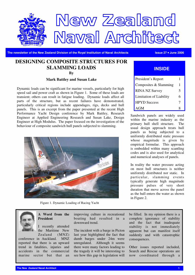
Dynamic loads can be significant for marine vessels, particularly for high speed sail and power craft as shown in Figure 1. Some of these loads are transient; others can result in fatigue loading. Dynamic loads affect all parts of the structure, but as recent failures have demonstrated, particularly critical regions include appendages, rigs, decks and hull panels. This is an excerpt from the paper presented at the recent High Performance Yacht Design conference by Mark Battley, Research Engineer at Applied Engineering Research and Susan Lake, Design Engineer at High Modulus. The paper focused on the investigation of the behaviour of composite sandwich hull panels subjected to slamming.
A Word from the President
I recently attended the Maritime New Zealand (MNZ)
conference in Auckland. MNZ reported that there is an upward trend in fatalities, injuries and accidents in the commercial marine sector but that an
improving culture in recreational boating had resulted in a downward trend.
The incident with a barge in Picton last year highlighted the fact that dumb barges under 24m were unregulated. Although it seems there were many factors leading to the tragedy it will be interesting to see how this gap in legislation will
be filled. In my opinion there is a complete ignorance of stability and the fact that inadequate stability is not immediately apparent but can manifest itself suddenly and with catastrophic consequences.
Other issues reported included, Search and Rescue operations are now coordinated through a
The newsletter of the New Zealand Division of the Royal Institution of Naval Architects Issue 27 •••• June 2006
DESIGNING COMPOSITE STRUCTURES FOR SLAMMING LOADS
By
Mark Battley and Susan Lake
Sandwich panels are widely used within the marine industry as the primary hull shell structure. The usual design approach treats hull panels as being subjected to a uniformly distributed static pressure whose magnitude is given by empirical formulae. This approach is embedded within many scantling codes and is also used for analytical and numerical analyses of panels.
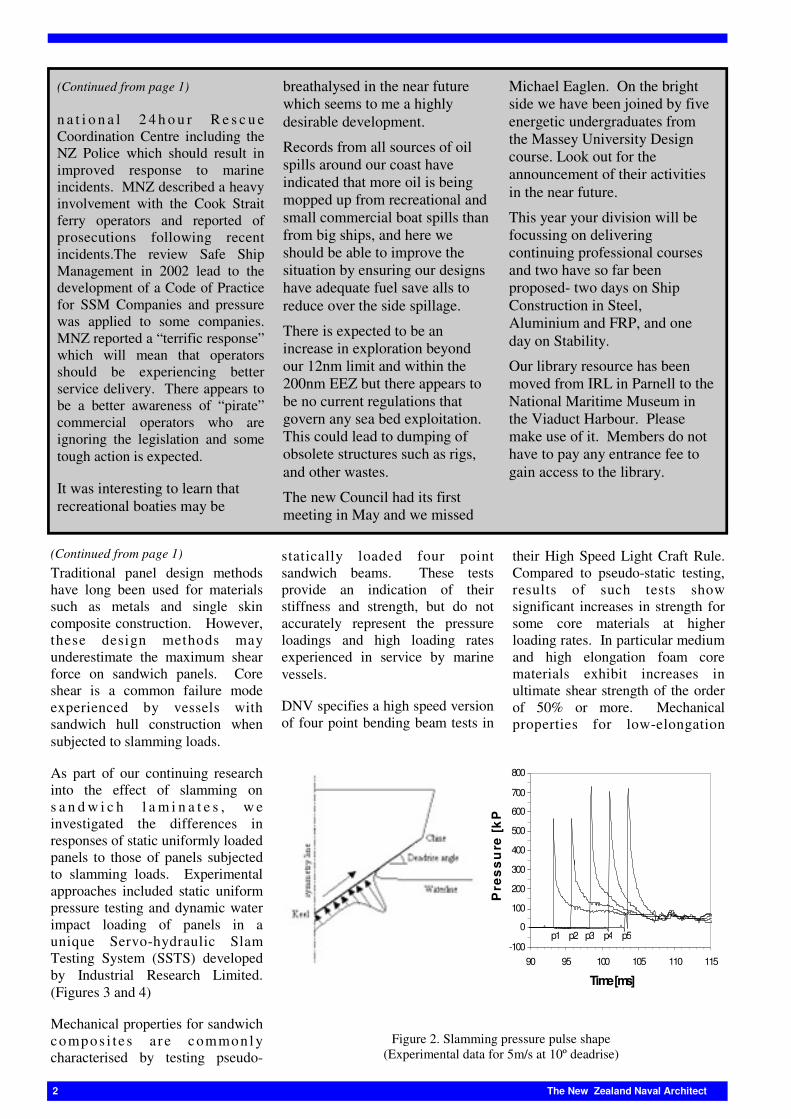
In reality the water pressure acting on most hull structures is neither uniformly distributed nor static. In part icular, slamming events typically generate high magnitude pressure pulses of very short duration that move across the panel as the hull enters the water as shown in Figure 2.
INSIDE
President’s Report 1
Composites & Slamming 1
RINA NZ Survey 5
AGM 8
Limitation of Liability 6
HPYD Success 7
Figure 1. Dynamic Loading of Racing Yacht
�
2 The New Zealand Naval Architect
Traditional panel design methods have long been used for materials such as metals and single skin composite construction. However, these design methods may underestimate the maximum shear force on sandwich panels. Core shear is a common failure mode experienced by vessels with sandwich hull construction when subjected to slamming loads.
As part of our continuing research into the effect of slamming on s a n d w i c h l a m i n a t e s , w e investigated the differences in responses of static uniformly loaded panels to those of panels subjected to slamming loads. Experimental approaches included static uniform pressure testing and dynamic water impact loading of panels in a unique Servo-hydraulic Slam Testing System (SSTS) developed by Industrial Research Limited. (Figures 3 and 4)
Mechanical properties for sandwich compos i te s a r e commonl y characterised by testing pseudo-
statically loaded four point sandwich beams. These tests provide an indication of their stiffness and strength, but do not accurately represent the pressure loadings and high loading rates experienced in service by marine vessels.
DNV specifies a high speed version of four point bending beam tests in
their High Speed Light Craft Rule. Compared to pseudo-static testing, results of such tests show significant increases in strength for some core materials at higher loading rates. In particular medium and high elongation foam core materials exhibit increases in ultimate shear strength of the order of 50% or more. Mechanical properties for low-elongation
(Continued from page 1)
n a t i o n a l 2 4 h o u r R e s c u e Coordination Centre including the NZ Police which should result in improved response to marine incidents. MNZ described a heavy involvement with the Cook Strait ferry operators and reported of prosecutions following recent incidents.The review Safe Ship Management in 2002 lead to the development of a Code of Practice for SSM Companies and pressure was applied to some companies. MNZ reported a “terrific response” which will mean that operators should be experiencing better service delivery. There appears to be a better awareness of “pirate” commercial operators who are ignoring the legislation and some tough action is expected.
It was interesting to learn that recreational boaties may be
breathalysed in the near future which seems to me a highly desirable development.
Records from all sources of oil spills around our coast have indicated that more oil is being mopped up from recreational and small commercial boat spills than from big ships, and here we should be able to improve the situation by ensuring our designs have adequate fuel save alls to reduce over the side spillage.
There is expected to be an increase in exploration beyond our 12nm limit and within the 200nm EEZ but there appears to be no current regulations that govern any sea bed exploitation. This could lead to dumping of obsolete structures such as rigs, and other wastes.
The new Council had its first meeting in May and we missed
Michael Eaglen. On the bright side we have been joined by five energetic undergraduates from the Massey University Design course. Look out for the announcement of their activities in the near future.
This year your division will be focussing on delivering continuing professional courses and two have so far been proposed- two days on Ship Construction in Steel, Aluminium and FRP, and one day on Stability.
Our library resource has been moved from IRL in Parnell to the National Maritime Museum in the Viaduct Harbour. Please make use of it. Members do not have to pay any entrance fee to gain access to the library.
(Continued from page 1)
-100
0
100
200
300
400
500
600
700
800
90 95 100 105 110 115
Time [ms]
Pre
ss
ure
[k
Pa
]
p1 p2 p3 p4 p5
�
Figure 2. Slamming pressure pulse shape (Experimental data for 5m/s at 10º deadrise)

The New Zealand Naval Architect 3
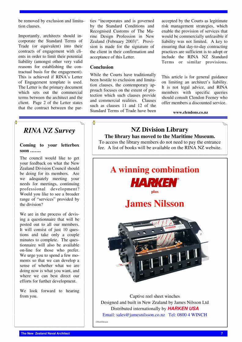
show the progression of the pressure pulse across the panel; the keel strain increasing at the start of the event and then remaining relatively constant, while the chine strain does not start to increase until approximately half way through the event then rises quickly, reaching its maximum when the panel is approximately 75% submerged.
Unlike the static panels the strains (and hence the transverse shear force) are different between the two edges of the panel, being higher at the chine edge. This is because this edge carries part of the load from
the residual pressure as well as the localised peak. All of the panels tested failed due to core shear fracture or plastic deformation at the chine edge.
In most design situations the key parameters for a panel are the transverse shear strength at the panel edge, and the bending strength and deflection at the panel centre. These were compared for the dynamic and statically loaded panels by measuring the surface strain near to the panel edge (which is indicative of the local transverse shear force), the surface strain at the panel centre (which is proportional to the bending moment) and the deflection at the panel centre.
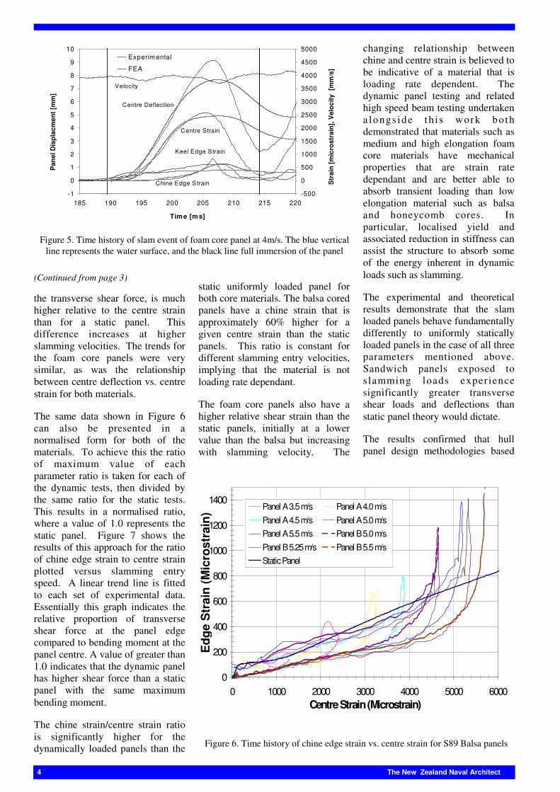
Figure 6 shows the time histories of the edge strain and centre deflection graphed against centre strain for a series of slamming tests of balsa cored panels and static tests of a balsa core panel. The figure shows that in the early part of the slamming event the chine edge strain is very low. Then as the pulse moves across the panel the chine edge strain increases suddenly, with only a very slight increase in centre strain. This implies that the shear force at the edge increases without a significant increase in bending moment at the centre of the panel. The maximum strain at the chine edge, and hence
(Continued on page 4)
materials such as balsa and honeycomb cores are much less dependent on loading rate.
The tests undertaken in this research were based on core materials that are commonly used in the slamming regions of sailing racing yachts and high-speed motor yachts. The dynamic test data was generated by repeated slamming tests with increasing impact velocity until panel failure. Panels with low elongation cores failed in a brittle manner whereas medium and high elongation cores failed due to permanent deformation. Transient dynamic finite element analysis was used to model the structural response of the sandwich panels to slamming events.
During slam testing of the sandwich panels a time history of the panel acceleration, instantaneous velocity, applied ram force, deflection at centre, and strains at the keel, centre and chine were recorded.
Figure 5 shows a typical slam test result at one speed (4m/s) for the C70-130 foam material, with the deflection and strains predicted by transient FEA. The keel and chine edge strains provide an indication of local deformation and hence transverse forces near the support edges. These two strains clearly
Figure 3. Servo-hydraulic slam testing system; Ram (1), load cell (2), specimen fixture (3), panel (4), side plates (5), back plate (6)
Figure 4. Typical slamming event in SSTS
4 The New Zealand Naval Architect
the transverse shear force, is much higher relative to the centre strain than for a static panel. This difference increases at higher slamming velocities. The trends for the foam core panels were very similar, as was the relationship between centre deflection vs. centre strain for both materials.
The same data shown in Figure 6 can also be presented in a normalised form for both of the materials. To achieve this the ratio of maximum value of each parameter ratio is taken for each of the dynamic tests, then divided by the same ratio for the static tests. This results in a normalised ratio, where a value of 1.0 represents the static panel. Figure 7 shows the results of this approach for the ratio of chine edge strain to centre strain plotted versus slamming entry speed. A linear trend line is fitted to each set of experimental data. Essentially this graph indicates the relative proportion of transverse shear force at the panel edge compared to bending moment at the panel centre. A value of greater than 1.0 indicates that the dynamic panel has higher shear force than a static panel with the same maximum bending moment.
The chine strain/centre strain ratio is significantly higher for the dynamically loaded panels than the
static uniformly loaded panel for both core materials. The balsa cored panels have a chine strain that is approximately 60% higher for a given centre strain than the static panels. This ratio is constant for different slamming entry velocities, implying that the material is not loading rate dependant.
The foam core panels also have a higher relative shear strain than the static panels, initially at a lower value than the balsa but increasing with slamming velocity. The
changing relationship between chine and centre strain is believed to be indicative of a material that is loading rate dependent. The dynamic panel testing and related high speed beam testing undertaken a longs ide t h i s work both demonstrated that materials such as medium and high elongation foam core materials have mechanical properties that are strain rate dependant and are better able to absorb transient loading than low elongation material such as balsa and honeycomb cores. In particular, localised yield and associated reduction in stiffness can assist the structure to absorb some of the energy inherent in dynamic loads such as slamming.
The experimental and theoretical results demonstrate that the slam loaded panels behave fundamentally differently to uniformly statically loaded panels in the case of all three parameters mentioned above. Sandwich panels exposed to s lamming loads exper ience significantly greater transverse shear loads and deflections than static panel theory would dictate.
The results confirmed that hull panel design methodologies based
(Continued from page 3)
Figure 6. Time history of chine edge strain vs. centre strain for S89 Balsa panels
0
200
400
600
800
1000
1200
1400
0 1000 2000 3000 4000 5000 6000Centre Strain (Microstrain)
Edg
e S
trai
n (M
icro
stra
in) Panel A 3.5 m/s Panel A 4.0 m/s
Panel A 4.5 m/s Panel A 5.0 m/sPanel A 5.5 m/s Panel B 5.0 m/s
Panel B 5.25 m/s Panel B 5.5 m/sStatic Panel
-1
0
1
2
3
4
5
6
7
8
9
10
185 190 195 200 205 210 215 220
Time [ms]
Pan
el D
ispl
acm
ent [
mm
]
-500
0
500
1000
1500
2000
2500
3000
3500
4000
4500
5000
Str
ain
[mic
rost
rain
], V
eloc
ity [
mm
/s]
Experim ental
FEA
Velocity
Centre Strain
Centre Deflection
Chine Edge Strain
Keel Edge Strain
�Figure 5. Time history of slam event of foam core panel at 4m/s. The blue vertical line represents the water surface, and the black line full immersion of the panel

The New Zealand Naval Architect 5
on uniform distributed pressure static panel analysis do not recognise the different load distributions within a slam-loaded panel, and may result in structures
with inadequate shear strength or stiffness. These results were not entirely unexpected given the history of core shear failures in composite yachts and launches,
however the results of the research allow design procedures to continue to be refined for slam regions of yachts and launches.
This work was supported by the New Zealand Foundation for Research, Science and Technology, and a Technology New Zealand Technology for Business Growth project. For more information about the High Performance Yacht design Conference, please visit: www.hpyd.org.nz, or for more information about the research contact Mark at [email protected] or Susan at [email protected].
The High Performance Yacht De-sign Conference (HPYD), held for the second time from 12th-14th Feb-ruary in Auckland, New Zealand, was once again a highly successful event, and has established itself as a regular date in the diary for consult-ants, academics and designers alike.
Whilst expectations were originally for 70 delegates, over 100 actually attended the event, including many of the world’s leading names in the field of yacht research, with nearly half of them travelling overseas to attend the conference which fea-tured 26 technical papers, with au-thors from 14 countries.
The public Design Session, held on the evening of the first day, profiled the Wally 130, a high performance yacht project being managed by Wally Yachts in Italy. The session, attended by over 200 people, was an opportunity not only for dele-gates to see the complex design process in action, but also for mem-bers of the public to find out more
about the work that goes into the glamorous yachts they often see sailing in and out of the local mari-nas.
There were many conference high-lights, but one in particular was the session on Optimisation and Design Process Automation. What was a small theme at the first High Per-formance Yacht Design Conference gathered significant momentum in the intervening three years. The trend is related to the developments in performance prediction in the 1970's and 80's, when the idea of commercially available VPPs that would enable designers to quantita-tively assess design options was considered far-fetched. Yet by the early 1990's such packages were available not only to the ‘grand prix’ designer but to cruising yacht designers all over the world.
Delegate feedback was extremely positive, with the quality of the pa-pers submitted and the presenta-tions themselves cited as being a cut
above many other conferences on the world circuit.
The organisers are pleased to an-nounce the third High Performance Yacht Design Conference will take place in February 2008.
0.0
0 .5
1 .0
1 .5
2 .0
2 .5
3.0 3.5 4 .0 4 .5 5.0 5.5 6 .0 6 .5Entry Velocity
Chi
ne S
trai
n/C
entr
e S
trai
nN
orm
alis
ed to
Sta
tic P
anel
C 70-130 Foam
S89 Ba lsa
Figure 7. Panel edge strain/panel centre strain normalised relative to static panels
HPYD Round-up By
Michael Eaglen

6 The New Zealand Naval Architect
The fees charged by a naval archi-tect usually represent only a small fraction of the total cost of construc-tion of a vessel. However, if issues arise from the services performed by the architect, the cost conse-quences to the architect could multi-ply significantly. Since an archi-tect’s gain is small relative to his potential loss, it is important for the architect to carefully limit his or her potential liability and therefore en-sure that the contract benefits are realised (ie, get paid).
RINA’s Letter of Engagement and Standard Terms of Trade were up-dated by Clendon Feeney in 2003. In early 2004, Clendon Feeney pre-sented a series of seminars on this contract set. The topics covered included the architect’s ability to exploit copyright in designs and the architect’s liability on allegations of negligent workmanship or other non-performance.
One aspect of the contract set which enables architects to limit potential liability is the use of exclusion and limitation clauses. Exclusion clauses attempt to remove potential grounds of claim, thereby excluding the architect’s liability completely in the specified areas. Limitation clauses seek to merely put a cap (usually a monetary one) on the ar-
chitect’s liability, but do not remove liability entirely. Recent law has recognised the use of exclusion and limitation clauses in commercial contracts as a legitimate means allo-cating economic risks and benefits between parties.
The relevant law For an exclusion or limitation clause to be enforceable, as with any con-tractual provision, it must form part of the “contract” at law. To achieve this, the client must have notice of the clause before or when the con-tract is made. The signature of a client is usually sufficient to make the accompanying written terms a binding and effective contract. Al-ternatively, a clause which is a stan-dard term will form part of a con-tract if it is part of the normal busi-ness practice between the parties, although there is significantly less certainty in enforcing a “contract” based on established business prac-tices rather than a written and signed acceptance of the specific contract terms.
RINA’s Standard Terms of Trade (2003) Clauses 11 and 12 of the Standard Terms of Trade (2003) provide:
11. MARINE DESIGNER NOT LI-ABLE FOR LOSSES
Except as otherwise provided for by the Consumer Guarantees Act 1993 for any work for a consumer as defined in that Act, the MARINE DESIGNER shall not be liable for:
the commercial performance of the Works;
any loss or damage arising by reason of any delay in the completion of the Works;
any loss of profits;
any indirect or consequential loss of whatever nature; or
any loss resulting from any errors or omissions arising from an oversight, a misinterpretation of a Client’s verbal instructions arising directly or indi-
rectly from any breach by the MA-RINE DESIGNER of any of its obliga-tions under this agreement or from any cancellation of this agreement or from any negligence on the part of the MA-RINE DESIGNER or its employees.
12. LIABILITY OF MARINE DE-SIGNER LIMITED
Except as provided for by the Consumer Guarantees Act 1993 for any work for a consumer as defined in that Act, if the MA-RINE DESIGNER or any sub-consultant shall be found liable to the Client (whether under the express or implied terms of this license, in negligence, or otherwise at com-mon law) for any costs, loss or damage suffered by the Client, however caused and of whatever nature, arising out of or con-nected with the performance or failure of performance of Services by the MARINE DESIGNER or any sub-consultant, then the maximum amount of that liability for all such claims against the MARINE DE-SIGNER and any sub-consultant shall not exceed the full value of the payment(s) made by the Client under the agreement between the parties.
Clause 11 is an exclusion clause. It lists the specific heads of losses for which the architect will not be li-able, including the commercial per-formance of a design, the client’s loss of profits and loss resulting from the architect’s negligence or breach of contract. Naval architects could otherwise easily be liable for these losses. This clause was also drafted in part to override provi-sions relating to remedies under the Contractual Remedies Act 1979.
Clause 12 is a limitation clause. If the architect is found to be liable to a client, this clause limits the quan-tum of any claim to the amount paid by the client to the architect. This clause specifically addresses the disparity between limited benefits to architects and the relatively huge potential losses they face.
Clauses 11 and 12 are modified when the client is a consumer. The Consumer Guarantees Act 1993 protects consumers by preventing businesses from contracting out of certain liabilities. The consumer’s right to particular remedies cannot
Limitation of liability by
Terence Lau—Clendon Feeney
The New Zealand Naval Architect 7
be removed by exclusion and limita-tion clauses.
Importantly, architects should in-corporate the Standard Terms of Trade (or equivalent) into their contracts of engagement with cli-ents in order to limit their potential liability (amongst other very valid reasons for establishing the con-tractual basis for the engagement). This is achieved if RINA’s Letter of Engagement template is used. The Letter is the primary document which sets out the commercial terms between the architect and the client. Page 2 of the Letter states that the contract between the par-
ties “incorporates and is governed by the Standard Conditions and Recognised Customs of The Ma-rine Design Profession in New Zealand (February 2003)”. Provi-sion is made for the signature of the client in their confirmation and acceptance of this Letter.
Conclusion While the Courts have traditionally been hostile to exclusion and limita-tion clauses, the contemporary ap-proach focuses on the extent of pro-tection which such clauses provide and commercial realities. Clauses such as clauses 11 and 12 of the Standard Terms of Trade have been
accepted by the Courts as legitimate risk management strategies, which enable the provision of services that would be commercially unfeasible if liability was not limited. A key to ensuring that day-to-day contracting practices are sufficient is to adopt or include the RINA NZ Standard Terms or similar provisions.
This article is for general guidance on limiting an architect’s liability. It is not legal advice, and RINA members with specific queries should consult Clendon Feeney who offer members a discounted service.
www.clendons.co.nz
A winning combination
plus
James Nilsson
Captive reel sheet winches
Designed and built in New Zealand by James Nilsson Ltd Distributed internationally by HARKEN USA
Email: [email protected] Tel: 0800 4 WINCH CRSL2005A.pub
RINA NZ Survey
Coming to your letterbox soon ……. The council would like to get your feedback on what the New Zealand Division Council should be doing for its members. Are we adequately meeting your needs for meetings, continuing professional development? Would you like to see a broader range of “services” provided by the division?
We are in the process of devis-ing a questionnaire that will be posted out to all our members. It will consist of just 10 ques-tions and take only a couple minutes to complete. The ques-tionnaire will also be available on-line for those who prefer. We urge you to spend a few mo-ments so that we can develop a sense of whether what we are doing now is what you want, and where we can best direct our efforts for further development.
We look forward to hearing from you.
NZ Division Library The library has moved to the Maritime Museum.
To access the library members do not need to pay the entrance fee. A list of books will be available on the RINA NZ website.
8 The New Zealand Naval Architect
NZ Council: President: John Harrhy
Helen Quekett [email protected]
Susan Lake [email protected]
Graeme Finch [email protected]
Brendan Fagen [email protected]
Jarrod Hall [email protected]
Roger Hill [email protected]
Dima Ivanov [email protected]
Philip Maxwell [email protected]
Daniel Upperton [email protected]
Nick De Waal [email protected]
The New Zealand Naval Architect is published quarterly.
All correspondence and advertising should be sent to:
The Editor The New Zealand Naval Architect C/o RINA New Zealand Division PO Box 91395 Auckland Mail Service Centre Auckland
Email:[email protected] Opinions expressed in this newsletter are not necessarily those of the Institution.
Administration and Membership enquiries Email: [email protected] Web Page: www.rina.org.nz UPDATE: [email protected]
The Royal Institution of Naval Architects (New Zealand Division) would like to acknowledge the continuing support of Clendon Feeney as our Honorary Solicitors. www.clendons.co.nz.
Forthcoming events
June 17th: Massey University Students Design Challenge Takapuna Boat Club, 9am Exhibition, 1pm Race
CPD courses in Ship Stability and Ship Construction Further details to be advised in RINA Update.
AGM – April 11th 2006
There was a good turn out to the RINA NZ Division AGM held at the Martitime Museum on April 11th. After hearing reports from the Treas-urer and President the new council was determined. Michael Eaglen stood down from the council and was thanked for all his hard work on the council both as a member and as President. Susan Lake, Roger Hill, Nic de Waal, Graeme Finch and John Harrhy will continue their term on the council along with Helen Quekett who agreed to stay on for a further six months as secretary and Newsline editor. Five student members, Dima Ivanov, Jarrad Hale, Philip Maxwell, Chris Moors and David Up-perton were elected to the council.
The Special Motions was then addressed. When RINA and the existing Naval Architectural Society of NZ were merged in January 2001, a pro-vision was made for a review of the merger arrangements after five years. If, after five years, the members were to decide that being a Divi-sion of RINA was not serving their needs and they would prefer to re-vert to.being an autonomous organization, then the merger would be reversed. The five year period having elapsed it was moved that the merger be made permanent and the (dormant) NASNZ be disestab-lished. A few members spoke from the floor all with positive feedback for the RINA NZ division and the increased profile it had attained. The following motions were then voted on and carried.
MOTION 1: "That the loan from Naval Architectural Society of New Zealand Incorporated to the Royal Institution of Naval Architects be forgiven"
MOTION 2: "That the Naval Architectural Society of New Zealand In-corporated be disestablished"
After the formal part of the evening the guest speaker, Bill Buckley, of Buckley Systems and co-owner of Maximus gave a talk entitled Design, Construction and Sailing Maximus from an owners and engineer’s per-spective. It was a fascinating account following the process behind the design and construction of the supermaxi and the development of the canting keel. The yacht was launched in February 2005 and undertook a challenging calendar of events warming up with the Auckland-Tauranga race, finding her stride in the Transatlantic Race and dominating the Fastnet.