designing and simulate an active pid controller for a
TRANSCRIPT

DESIGNING AND SIMULATE AN ACTIVE PID CONTROLLER FOR A VEIDCLE
SUSPENSION SYSTEM VIA CONTROLLABLE DAMPING DEVICES
by
Mohd Ridhuan Bin Dams
Dissertation submitted in partial fulfilment of
the requirements for the
Bachelor of Engineering (Hons)
(Mechanical Engineering)
JUL¥2009
Universiti Teknologi PETRONAS
Bandar Seri Iskandar
31750 Tronoh
Perak Darul Ridzuan

CERTIFICATION OF APPROVAL
DESIGNING AND SIMULATE AN ACTIVE PID CONTROLLER FOR A VEIDCLE
SUSPENSION SYSTEM VIA CONTROLLABLE DAMPING DEVICES
Approved:
Dr. Vu Trieu Minh
Project Supervisor
by
Mohd Ridhuan Bin Darus
A project dissertation submitted to the Mechanical Engineering Programme Universiti Teknologi PETRONAS
in partial fulfillment of the requirement for the Bachelor of Engineering (Hons)
(Mechanical Engineering)
UNNERSITI TEKNOLOGI PETRONAS
TRONOH, PERAK
Nov2009
1

CERTIFICATION OF ORIGINALITY
This is to certiey that I am responsible for the work submitted in this project, that the original
work is my own except as specified in the references and acknowledgements, and that the
original work contained herein have not been undertaken or done by unspecified sources or
persons.
2

ABSTRACT
This report was prepared mainly for the purpose of giving a brief idea on the understanding of
the chosen project. It is also basically discusses the preliminary research done on the topic,
which is Designing and simulate an active PID controller for a vehicle suspension system
via controllable damping devices. The objective of this project is to simply design a vehicle
suspension system by using Simulink in Matlab and performing a real-time simulation depicting
the necessary information in regard to the objective of this project. By saying that the old
fashioned conventional passive suspension system cannot be able to provide a safety driving and
comfort for the driver, the active suspension system will do. Implying a closed-loop controller
for the vehicle suspension system will assist by reacting to an error signal and supply an output
for correcting elements. A controllable damping device will serve as a mean that allows the
implication of an active suspension system is been done. Main problem in these days is to find
the best configuration that the driver favors in a real-time situation. Therefore, after I have ran
through a series of simulations and testing it is shown that it is easier to execute the Matlab
programme in the 2-(lof and 4-(iof which consist of roll and pitch rather than the 7-(lof system.
But after all, it is not an excuse for not completing the 7 -(lof vehicle suspension system and carry
out the simulation with less disturbances.
3

ACKNOWLEDGEMENTS
The author wishes to take the opportunity to express his utmost gratitude to the individual that
have taken the time and effort to assist the author in completing the project. Without the
cooperation of these individuals, no doubt the author would have faced some minor
complications throughout the course.
First and foremost the author's utmost gratitude goes to the author's supervisor; Dr. Vu Trieu
Minh, without his guidance and patience, the author would not be succeeded to complete the
project. To the Final Year Research Project Coordinator, Dr Hasnain Isa and Mrs Husna for
provide his with all the initial information required to begin the project.
To the entire technician in Mechanical Department, especially for those who been assisting me
with the MatLab software thank you again for assisting the author in completing his project.
To all individuals that has helped the author in any way, but whose name is not mentioned here,
the author would like to express his earnest gratitude to all.
4

Contents
CHAPTER 1: INTRODUcrJON ................................................................................................................ 7
1.1 BACKGROUND OF STUDY .......................................................................................................... 7
1.2 PROBLEM STATEMENT ............................................................................................................. 7
1.3 OBJECTIVES AND SCOPE OF STUDY ........................................................................................... 8
CHAPTER 2: UTERATURE REVIEW ........................................................................................................ 9
2.1 INTRODUCTION ............................................................................................................... H ....... 9
2.2 VEHICLE SUSPENSION SYSTEM .................................................................................................. 9
2.2.1 ACTIVE SUSPENSION ....................................................................................................... 12
2.2.2 SEMI-ACTIVE SUSPENSION .............................................................................................. 13
2.3 INTRODUCTION TO VEHICLE SUSPENSION SYSTEM ................................................................. 14
2.3.1 ACTIVE SUSPENSIONS ..................................................................................................... 20
2.4 THE ACTIVE SUSPENSION INVESTIGATED AT UNIVERSITY OF BATH ......................................... 2S
2.5 PID CONTROLLER .................................................................................................................... 26
2.6 SKYHOOK CONTROL OF AN SDOF SYSTEM .............................................................................. 27
2.7 MAGNETORHEOLOGICAL DAMPER ......................................................................................... 28
CHAPTER 3: METHODOLOGY ............................................................................................................. 35
3.1 RESEARCH METHODOLOGY .................................................................................................... 35
3.2 PROJECT IDENTIFICATION ....................................................................................................... 35
3.2.1 7-DOFs VEHICLE SUSPENSION SYSTEM ................................................................................ 35
3.2.1.1 (A) % MODEL, 2-DOFs SUSPENSION SYSTEM ....................................................................... 36
3.2.1.2 (B) :Y.i MODEL, 4-DOFs (PITCH) SUSPENSION SYSTEM ........................................................... 38
3.2.1.3 (C) :Y.i MODEL, 4-DOFs (ROLL) SUSPENSION SYSTEM ............................................................ 39
3.2.1.3 (C) FUU MODEL, 7-DOFs SUSPENSION SYSTEM .................................................................. 40
3.3 TOOL .................................................................................................................................... 42
CHAPTER 4: RESULTS AND DISCUSSIONS ........................................................................................... 43
4.0 RESULTS ................................................................................................................................. 43
4.1 7-DOFs VEHICLE SUSPENSION SYSTEM .................................................................................... 44
CHAPTER 5: CONCLUSION .................................................................................................................. 54
5

LIST OF FIGURES
Figure 1: McPherson suspension ............................................................................................................ 15
Figure 2: Double-wishbone suspension .......•........................................................................................... 15
Figure 3 :Shock absorbers .................................. .............................................................................. ...... 16 Figure 4 : Damper spring and damper system ........................................................................................ 16 Figure 5: Springs ................................................................................................................................... 17
Figure 6 : Quarter-car model .................................................................................................................. 18
Figure 7: Full vehide model ....................... ............................................................................................ 19
Figure 8: Simple diagram of an active suspension ............................................. ..................................... 21
Figure 9 : Damper with controllable orifice ............................................................................................. 23
Figure 10: Partides in MR damper ......................................................................................................... 23
Figure 11 :Fully active suspension .......................................................................................................... 24
Figure 12 : Architecture of a system ....................................................................................................... 26 Figure 13 : PID controller ........................................................................................................................ 26 Figure 14: Skyhook ................................................................................................................................ 28 Figure 15: Functional representation ..................................................................................................... 30
Figure 16: LORD MR compact damper visual and actual ........................................................................ 31
Figure 17: Uneardampercharacteristics ............................................................................................... 32
Figure 18: Bilinear, Asymmetric Damping Characteristics ...................................................................... 33
Figure 19: Ideal MR damper performance ............................................................................................. 33
Figure 20: MR damper performance envelope ....................................................................................... 34
Figure 21 : 1/4 model of the 2-DOF's suspension system ........................................................................ 36
Figure 22 : 1/4 model without C ............................................................................................................. 37
Figure 23 : 1/2 model of4--DOF's suspension system (pitch} ....................•............................................... 38
Figure 24: 1/2 model (ro/1} .... ................................................................................................................. 39
Figure 25 : Full model 7-DOF's suspension system .................................................................................. 40
Figure 26: Full model of 7-DOFs suspension system ............................................................................... 45
Figure 27: Simulink of the front-left-car dynamic equations ................................................................... 46
Figure 28 : Simulinkfor the rear-left-car dynamic equation .................................................................... 47
Figure 29: Simulink for the rear-right-car dynamic equation .................................................................. 48
Figure 30: Simulink of the front-right-car dynamic equation .................................................................. 49
Figure 31 : Simulink of the vehide overall mass ...................................................................................... 51 Figure 32 : Simulink of the 4-dof pitch vehide suspension system ........................................................... 52
Figure 33 : Simulink of the 4-dof roll suspension system ......................................................................... 53
6

CHAPTER1: INTRODUCTION
1.1 BACKGROUND OF STUDY
The roads commonly used by motor vehicles are uneven. This unevenness causes vertical
movements of the vehicle and the passengers during the driving process. The vehicle is
connected to the road by the tire. Small unevenness in comparison to the tire contact patch size
can be compensated by the tire elasticity, whereas larger unevenness entails a vertical
acceleration or deflection of the wheels. In order not to transfer these accelerations into the
vehicle structure, a length compensating element has to be placed between the wheel and the
vehicle structure. Steel springs are the technologically simplest elements with variable length.
Due to this fact it is also the most common length compensating element, whose force is a
function of the length variation. It is usually used in the suspensions of motor vehicles. Different
parts connected with springs generate oscillating systems. So there has to be added an energy
absorbing element, the damper. Most suspension systems are passive or reactive. For example, a
tire hitting a bump or dropping into a hole may not stay in contact with the road surface. The
suspension system then reacts by compressing or extending the spring. These actions affect
handling and ride quality, and send shock and vibration to the vehicle body. Therefore, the need
for an active suspension system is vital to be taken into consideration.
1.2 PROBLEM STATEMENT
Every cars manufacturer has been emphasizing the point of maintaining a comfort ride and
maximizing the safety while driving as their major aspect when producing a car. The main
concern in achieving those prospects relies in the suspension system which they cannot simply
put it aside without taking serious study on it. According to the present data which being shared
by the supervisor noting that a normal conventional passive suspensions only consist of the
spring and damping properties which are time-invariant. Passive elements can only store energy
7

for some portion of a suspension cycle (springs) or dissipate energy (shock absorbers). No
external energy is directly supplied to this type of suspension. This consequence clearly gives a
picture where such vehicle cannot set the parameters of the suspension in regards to the desired
output that provide comfort and safety driving to the driver.
1.3 OBJECTIVES AND SCOPE OF STUDY
The main objective of this research is:
./ To complete the 7-dof suspension system and carry out respective simulation in regards
to the stated problem
Currently, author in the phase where a full scale model of a car suspension system is to be
implemented and further designing a 7-dofvehicle suspension system. And upon completion of
the 7 -dof vehicle suspension system, author will carry out the simulation and testing to further
complete the objective.
8
CHAPTERZ: LITERATURE REVIEW
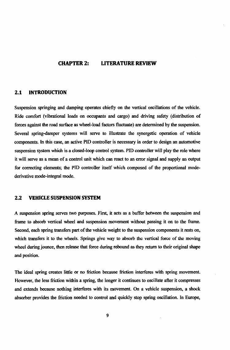
2.1 INTRODUCTION
Suspension springing and damping operates chiefly on the vertical oscillations of the vehicle.
Ride comfort (vibrational loads on occupants and cargo) and driving safety (distribution of
forces against the road surface as wheel-load factors fluctuate) are determined by the suspension.
Several spring-damper systems will serve to illustrate the synergetic operation of vehicle
components. In this case, an active PID controller is necessary in order to design an automotive
suspension system which is a closed-loop control system. PID controller will play the role where
it will serve as a mean of a control unit which can react to an error signal and supply an output
for correcting elements; the PID controller itself which composed of the proportional mode
derivative mode-integral mode.
2.2 VEHICLE SUSPENSION SYSTEM
A suspension spring serves two purposes. First, it acts as a buffer between the suspension and
frame to absorb vertical wheel and suspension movement without passing it on to the frame.
Second, each spring transfers part of the vehicle weight to the suspension components it rests on,
which transfers it to the wheels. Springs give way to absorb the vertical force of the moving
wheel during jounce, then release that force during rebound as they return to their original shape
and position.
The ideal spring creates little or no friction because friction interferes with spring movement.
However, the less friction within a spring, the longer it continues to oscillate after it compresses
and extends because nothing interferes with its movement. On a vehicle suspension, a shock
absorber provides the friction needed to control and quickly stop spring oscillation. In Europe,
9

shock absorbers are known as "dampers", which is actually a more accurate name, since the
springs actually absorb road shocks while shock absorbers damp the spring action. Automotive
shock absorbers use hydraulic friction, rather than mechanical, or surface-to-surface, friction to
control spring oscillation.
Like mechanical friction, hydraulic friction generates heat by resisting movement. However,
unlike mechanical friction, hydraulic friction is created without surface-to-surface contact
between the moving parts. Therefore, a hydraulic shock absorber has a much longer service life
than a mechanical device designed to perform the same task. The movement a shock absorber
resist is suspension movement, since one end of the shock mounts to the frame and the other end
attaches to a suspension member. The heat created by the internal hydraulic resistance of the
shock absorber dissipates into the air surrounding the shock.
Listed below are a number of model of cars which has been implying active suspension/adaptive
suspension system since the early of 19's dating until this present day
• 1987 Mitsubishi Galant "Dynamic ECS", world's first production semi-active electronically
controlled suspension system
• 1989 Citroen XM (Hydractive, semi-active)
• 1990 Infiniti Q45 "Full-Active Suspension (F AS)", world's first production fully active
suspension system
• 1990 Toyota Supra (Toyota Electronically Managed Suspension, TEMS)
• 1991 Mitsubishi GTO "Electronic Controlled Suspension"
• 1991 Toyota Soarer 'Active'
• 1992 Toyota Celica (Japan only)
• 1992 Citroen Xantia VSX (Hydractive 2, semi-active)
• 1993 Cadillac, several models with road sensing suspension.
• 1994 Citroen Xantia Activa (Hydractive 2 and active roll control)
• 1996 Jaguar XK8 'CATS' (optional)
• 1997 Jaguar XJ 'CATS' (standard on XJR model)
• 1999 Mercedes-Benz CL-Class, Active Body Control
10
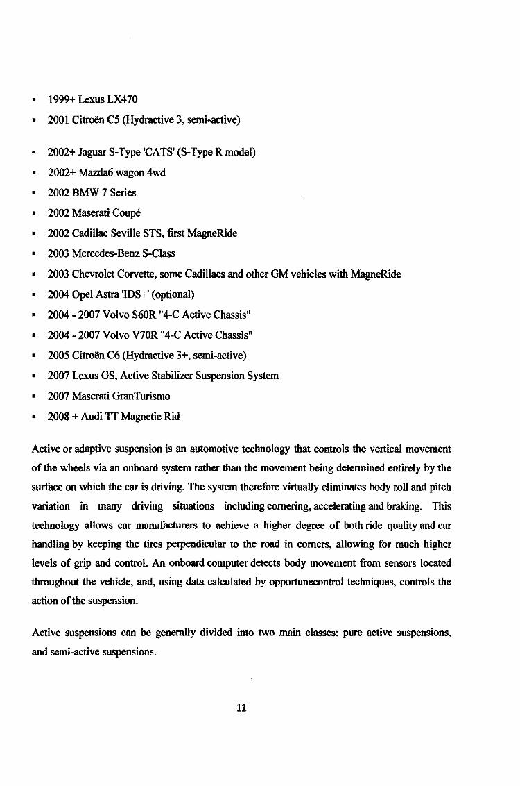
• 1999+ Lexus LX470
• 2001 Citroen C5 (Hydractive 3, semi-active)
• 2002+ Jaguar S-Type 'CATS' (S-Type R model)
• 2002+ Mazda6 wagon 4wd
• 2002 BMW 7 Series
• 2002 Maserati Coupe
• 2002 Cadillac Seville STS, first MagneRide
• 2003 Mercedes-Benz S-Class
• 2003 Chevrolet Corvette, some Cadillacs and other GM vehicles with MagneRide
• 2004 Opel Astra 'IDS+' (optional)
• 2004- 2007 Volvo S60R "4-C Active Chassis"
• 2004-2007 Volvo V70R "4-C Active Chassis"
• 2005 Citroen C6 (Hydractive 3+, semi-active)
• 2007 Lexus GS, Active Stabilizer Suspension System
• 2007 Maserati GranTurismo
• 2008 + Audi TT Magnetic Rid
Active or adaptive suspension is an automotive technology that controls the vertical movement
of the wheels via an onboard system rather than the movement being determined entirely by the
surface on which the car is driving. The system therefore virtually eliminates body roll and pitch
variation in many driving situations including cornering, accelerating and braking. This
technology allows car manufacturers to achieve a higher degree of both ride quality and car
handling by keeping the tires perpendicular to the road in comers, allowing for much higher
levels of grip and control. An onboard computer detects body movement from sensors located
throughout the vehicle, and, using data calculated by opportunecontrol techniques, controls the
action of the suspension.
Active suspensions can be generally divided into two main classes: pure active suspensions,
and semi-active suspensions.
11

2.2.1 ACTIVE SUSPENSION
Active suspensions, the first to be introduced, use separate actuators which can exert an
independent furce on the suspension to improve the riding characteristics. The drawbacks of this
design (at least today) are high cost, added complication/mass of the apparatus needed for its
operation, and the need for rather frequent maintenance and repairs on some implementations.
Maintenance can also be problematic, since only a factory-authorized dealer will have the tools
and mechanics who know how to work on the system, and some issues can be difficult to
diagnose reliably.
Citroen's Active Wheel incorporates an in-wheel electrical suspension motor that controls torque
distribution, traction, turning maneuvers, pitch, roll and suspension damping for that wheel, in
addition to an in-wheel electric traction motor.
Hydraulic actuated
Hydraulically actuated suspensions are controlled with the use of hydraulic servomechanisms.
The hydraulic pressure to the servos is supplied by a high pressure radial piston hydraulic pump.
Sensors continually monitor body movement and vehicle ride level, constantly supplying the
computer with new data.
As the computer receives and processes data, it operates the hydraulic servos, mounted beside
each wheel. Almost instantly, the servo regulated suspension generates counter forces to body
lean, dive, and squat during various driving maneuvers.
In practice, the system has always incorporated the desirable self-levelling suspension and height
adjustable suspension features, with the latter now tied to vehicle speed for
improved aerodynamic performance, as the vehicle lowers itself at high speed.
Colin Chapman - the inventor and automotive engineer who founded Lotus Cars and
the Lotus Formula One racing team - developed the original concept of computer management of
hydraulic suspension in the 1980s, as a means to improve cornering in racing cars. Lotus
developed a version of its 1985 Excel model with electro-hydraulic active suspension, but this
was never offered to the public.
12

Computer Active Technology Suspension (CATS) co-ordinates the best possible balance
between ride and handling by analysing road conditions and making up to 3,000 adjustments
every second to the suspension settings via electronically controlled dampers.
Electromagnetic recuperative
This type of active suspension uses linear electromagnetic motors attached to each wheel
independently allowing for extremely fast response and allowing for regeneration of power used
through utilizing the motors as generators. This comes close to surmounting the issues with
hydraulic systems with their slow response times and high power consumption. It has only
recently come to light as a proof of concept model from the Bose company, the founder of which
has been working on exotic suspensions for many years while he worked as an MIT professor.
2.2.2 SEMI-ACfiVE SUSPENSION
Semi-active systems can only change the viscous damping coefficient of the shock absorber, and
do not add energy to the suspension system. Though limited in their intervention (for example,
the control force can never have different direction than that of the current speed of the
suspension), semi-active suspensions are less expensive to design and consume far less energy.
In recent times, research in semi-active suspensions has continued to advance with respect to
their capabilities, narrowing the gap between semi-active and fully active suspension systems.
Solenoid/valve actuated
This type is the most economic and basic type of semi-active suspensions. They consist of a
solenoid valve which alters the flow of the hydraulic medium inside the shock absorber,
therefore changing the dampening characteristics of the suspension setup. The solenoids are
wired to the controlling computer, which sends them commands depending on the control
algorithm (usually the so called "Sky-Hook" technique).
13

Magneto rheological damper
Another fairly recently-developed method incorporates magneto rheological dampers with a
brand name MagneRide. It was initially developed by Delphi Corporation for GM and was
standard, as many other new technologies, for Cadillac Seville STS (from model 2002}, and on
some other GM models from 2003. This was an upgrade for semi-active systems ("automatic
road-sensing suspensions") used in upscale GM vehicles for decades, and it allows, together with
faster modero computers, changing the stiffness of all wheel suspensions independently on every
road inch on highway speed. These dampers are finding increased usage in the USA and already
leases to some foreign brands, mostly in more expensive vehicles. In this system, being in
development for 25 years, the damper fluid contains metallic particles. Through the onboard
computer, the dampers' compliance characteristics are controlled by an electromagnet.
Essentially, increasing the current flow into the damper raises the compression/rebound rates,
while a decrease softens the effect of the dampers. Information from wheel sensors (about
suspension extension}, steering, acceleration sensors and some others is used to calculate the
optimized stiffness. Very fast reaction of the total system allows, for instance, make softer
passing by a single wheel above a bump or a rock on the road.
2.3 INTRODUCTION TO VEHICLE SUSPENSION SYSTEM
As one of the most important systems in a vehicle the suspension is a major focus of automotive
engineers. Suspension is the term given to the system of shock absorbers and springs as well as
linkages, which connect a vehicle to its wheels. Its main functions are to isolate vehicle body
from road induced vibration, to maintain contact between tyre and road, to Control body pitch
and roll, to limit wheel movement, and to support range ofloads.
14

Figure 1: McPherson suspension
Figure 2: Double-wishbone suspension
The first one is called McPherson suspension. The shock absorber (also known as damper) and
the coil spring are attached to an A -arm at the bottom to the wheel and attached at the top to the
vehicle body. The second one is a double-wishbone suspension. It has two parallel wishbone
shaped arms to locate the wheel. Each wishbone (or arm) has two mounting positions to the
chassis and one at the wheel hub. The shock absorber and coil spring mount to the wishbones to
control vertical movement.
15

Hydraulic shock absorbers are most often used in a vehicle suspension. It can dissipate the
kinetic energy in the system and convert it into heat.
Figure 3 : Shock absorbers
Picture above shows three types of hydraulic shock absorbers used in automotive applications.
Whenever the hydraulic oil flow through the damper valve in the shock absorber, damping force
is generated. The more restrictive the damper valve is, the more damping force can be generated.
\ I " r... \ I v I
, ••. 1 I t•""
Figure 4 : Damper spring and damper system
16

Damped spring &damper system demonstrates the effects of a shock absorber on the body
movement. It can reduce the oscillation of the suspension movement by dissipating the energy. It
is customary to have less damping for compression motion than that of extension motion so that
less force is transmitted to the vehicle when it encounters bump-type disturbance. By
comparison, more damping is provided for rebound motion in order to quickly dissipate energy
stored in the suspension system.
Vehicle Models
When we design or analyse a suspension system, we need a physical model.
Leofspring cat sp;ng
T arsion bar
Gasspnog Rubber spring
Figure 5 : Springs
17

Figure 6: Quarter-car made/
Quarter car model shows a simplified linear quarter car modeL Each corner of the vehicle can be
simplified as a body mass, a suspension (which is composed of a shock absorber I damper and a
spring) and a tyre mass. It is assumed there is a spring in the tyre to model the compressibility of
the tyre. The movement of the vehicle body is as going to be mentioned in the next chapter.
If we extend the quarter car model to the full vehicle, we can get a full vehicle model as shown
below.
18

"!/ -----~..--
Figure 7: Full vehicle model
Besides the vertical movement at each comer, the vehicle body also has three rotational
movements, the roll, pitch and yaw.
How to evaluate a suspension performance
Experienced drivers used to carry out subjective assessments to judge a suspension performance.
They drive the car over all kinds of roads and judge the suspension by personal feelings, e.g.
noise, vibration and harshness. However, people's feelings are tricky and sometimes for the same
car drivers may have different subjective judgements. Therefore, we need some objective
standards to evaluate a suspension performance.
In vehicle suspension designs, there are 4 main criteria to objectively evaluate a suspension
performance. The first is the body acceleration, which is used to assess ride comfort. Previous
research has shown that the vehicle body acceleration is highly related to a passenger's feeling
about ride comfort. The second is the dynamic tyre deflection, which is connected with handling
performance. When a tyre deflection is too big, it may lose contact with the road. In this case, the
driver can lose control of the vehicle. The third is the suspension deflection which means the
suspension should have enough working space. When the suspension deflection is too big, the
wheel may hit the vehicle body and make the driving very harsh. The last one is the body
19

attitude. We want to keep the vehicle body level all the time during the driving; therefore pitch,
roll and warp angle are very important.
Since the body acceleration is related to the feeling of a human being, how will it affect a
driver's judgement? Modem vehicle tends to have a natural frequency of about l.0-2.0Hz. The
reason is that this frequency is very close to the way an adult is walking based on a pace of JOin
and speed of 2.5-4mph. Previous medical researches have proven that most uncomfortable
frequencies lie in 20-200Hz. For example, if people are exposed to 4-8Hz vertical vibrations,
they will soon get fatigued. Human head and neck are sensitive to 18-20Hz vibrations and
visceral region is sensitive to 5-7Hz vibrations. Besides the high frequency vibrations, some low
frequency vibrations can also make people feel uncomfortable. For example, sea sickness is
related to the vibrations below 0.75Hz. Also, lateral and pitch movements can make people feel
uncomfortable.
Trade-offs in suspension design
In the past years automotive engineers are trying every method to improve the suspension
design. However, due to some inherent trade-offs in suspension itself, it is very difficult to
design a perfect suspension. The best known is the compromise between ride and handling. For
example, to have a comfortable ride, soft spring and damper are helpful; however, the soft spring
and damper may result in excessive tyre movement and make the handing worse. On the other
hand, to stiff the spring and damper for a good handling may make the suspension feel very
harsh. Accordingly, most conventional passive suspensions may only satisfY the essential
requirements and will compromise on some of the less important considerations. For example,
luxury limousines tend to use soft suspensions to offer good ride comfort, while sports cars
usually have stiff suspensions to achieve superior handling performance.
2.3.1 ACTIVE SUSPENSIONS
With the development of modem computers, electronics, hydraulics and control technologies, a
new suspension system; the active suspension, provides a possible solution to the conflict
requirements between ride and handling. An active suspension refers to a suspension system
20

which uses a micro-computer and sensors in a feedback loop to improve the suspension
performance.
nal influences road, side wind, .
Jlt'EIS&II'I!l ~·~>'llal r.>OSilia"l
ospeed ~ering input ECU
rid!!Nlighl '------4, OOdy i!e<>!!lt<rillion .14-----....1
Sen scm
Figure 8 : Simple diagram of an active suspension
Arrangement of an active suspension shows a typical arrangement of the active suspension. In
general, it is composed of:
• Sensors - various sensors are installed around the vehicle to monitor the vehicle
conditions and driver activities.
• Electronic control unit (ECU) - all the sensor signals are fed to a microcomputer, also
known as ECU. With the aid of a programmed map memory, calculations are made as to
what adjustment should be made to the suspension.
• Actuators - the instructions from ECU are converted into electrical signals and directed
to various actuators to control the suspension. Hydraulic actuators are most often used for
their compact volume and light weight.
21

Categories of active suspensions
Depending on various hardware employed in active suspensions, they can be divided into four
categories.
Semi-active suspensions
The term semi-active suspension is often used to refer to a controlled damper under closed-loop
control, which means the control is realized by varying the damper's damping rate
{_--Mil--
Semi-active suspension
A semi-active suspension is only capable of dissipating energy. According to different damper
configurations, semi-active dampers can be classified into the following categories.
Dampers with controllable orifice
The damping force in a shock absorber is generated when the oil flow through the hydraulic
orifices in the damper valve of the shock absorber. The smaller the orifice is, the larger damping
force can be generated. Therefore, we can control the opening of the orifice to adjust the
shocker's damping force. Currently ZF Sachs (a German tier I company) offers a line of semi
active shock absorbers under the name of CDC (continuously damping control) as shown below.
22

Figure 9 : Damper with cantrol/ab/e orifice
Dampers with controllable fluid
If the hydraulic orifice is fixed, we can vary the oil viscosity to control the damping force. The
bigger the oil viscosity is, the larger damping force can be generated. ER (Electrorheological) or
MR (Magneto-rheological) fluid can be used for this purpose. There are polarizable particles of a
few microns in the oil. When electrical of magnetic field is applied to the oil, the particles will be
polarised and distributed in a sequential order as shown in.
,,, ... ? '
• • •• •• • • • •• IP?JIIm m·iil~ • I • ""'--'··'
t • ..
Figure 10 : Particles in MR damper
23

Work principle of electro-heological & magnetorheological dampers: Particles in an MRIER
fluid left without & right with applied magnetic/electrical field.
As a result, the oil viscosity changes, depending on the strength of the electricaVmagnetic filed.
Semi-active suspensions have been successfully used in some vehicle models, e.g. Audi AS,
Lancia Thesis and the new Opel I Vauxhall Astm.
Fully active suspensions
Different from semi-active suspensions, a fully active suspension does not change the damper
chamcteristics, but add a force genemtor in pamllel with the passive damper and spring as shown
in
Figure 11 : Fully active suspension
Therefore, the suspension can not only dissipate energy, but also inject energy into the system.
That is why we call it fully active suspension. Normally the power of the force genemtor is
supplied by the engine; therefore, compared with semi-active suspensions, active suspensions
have higher cost and power consumptions. But as a return, it has better perform-ance than semi
active ones. Depending on the response speed of the actuator, there are fast active and slow
active suspensions. Slow active suspensions have low cost and power consumption, but the
performance is not as good as fast active ones.
24

The applications of fully active suspension can be found on Toyota Soarer, Nissan Q45A and
some Mercedes-Benz models, for example, the SLSOO.
2.4 THE ACTIVE SUSPENSION INVESTIGATED AT UNIVERSITY OF BATH
Introduction
Cooperated with Jaguar, Ford and TOKICO (USA) Inc, a prototype hydro-pneumatic active
suspension has been investigated at the University of Bath. From individual components to
overall system, extensive computer simulations and experimental measurements were carried
out. It is hoped that this work could lead to further understandings and improved designs of a
computer controlled active suspension. For confidential considerations, no detailed information
about the system is enclosed with this talk.
The active suspension system
The active suspension investigated in this research shows the layout of the active suspension
investigated in this research. It is a fully slow active suspension system. The power is supplied
by a gear pump driven by the engine. The oil from the pump goes through a fail safe valve unit
first. This unit has two main functions. The first is to shut off the system in case of emergency. In
this circumstance the system will behave as a passive suspension. The second is to adjust the
supply pressure. When the active suspension need not work, the fail safe valve unit will reduce
the supply pressure level. It increases supply pressure only when it is necessary. In this way, the
system power consumption is reduced. Then the oil goes to a flow control valve at each comer,
which controls the flow to and from the gas strut (composed of a coil spring and a gas shock
absorber) to adjust the suspension movement. The flow control valve is controlled by an ECU,
which makes judgement upon receiving various sensor signals around the vehicle.
The prototype active suspension was implemented on a Jaguar S-Type saloon and extensive
experiments carried out.
25

Gasscnrt ~----,
I I I I I
~----~~-----~----=1==--~-~~---~---~--L--+---' I
:ler.ation semr.or - - - - - - -Hefglt 1oel!Kr - - - - - - -
"'~""'re ~n:.cv- - - - - - -t~SWIIIOt-- -----
ECU
I I I
1----- _I I __________________ I
--------------------1
I <~·-1 r-------
.BraJoe SMSU - - - - - - -~ $Eli'J»CCr. ~&tc -- - - - - -
~-------------------------------..__ ___ _,
Figure 12 : Architecture of a system
2.5 PID CONTROLLER
PID Controller (closed-loop controller) is a combination of all three modes of control
(proportional, integral and derivative) which enables a controller to be produced and has no
offset error and reduces the tendency for oscillations. Such a controller is known as a three-mode
controller or the well-known PfD controller.
Figure 13 : PID controller
Kp = proportional gain
26

Kl = integral gain
Kd = derivative gain
The variable (e) represents the tracking error, the difference between the desired input value (R)
and the actual output (Y). This error signal (e) will be sent to the PID controller, and the
controller computes both the derivative and the integral of this error signal. The signal (u) just
past the controller is now equal to the proportional gain (Kp) times the magnitude of the error
plus the integral gain (Ki) times the integral of the error plus the derivative gain (Kd) times the
derivative of the error.
This signal (u) will be sent to the plant, and the new output (Y) will be obtained. This new output
(Y) will be sent back to the sensor again to fmd the new error signal (e). The controller takes this
new error signal and computes its derivative and it's integral again. This process goes on and on.
2.6 SKYHOOK CONTROL OF AN SDOF SYSTEM
One method to eliminate the tradeoff between resonance control and high frequency isolation is
to reconsider the confignration of the suspension system. For instance, consider moving the
damper from between the suspended mass and the base to the position shown in Fig. 2.9. The
damper is now connected to an inertial reference in the sky (i.e., a ceiling that remains vertically
fixed relative to a ground reference). Notice that this is a purely fictional configuration, since for
this to actually happen, the damper must be attached to a reference in the sky that remains fixed
in the vertical direction, but is able to translate in the horizontal direction. Ignoring this problem
at the moment, we will focus on the performance of this configuration.
27

Figure 14: Skyhook
The transmissibility of this configuration can be derived to be
_J_c = --------
Another approach to achieving skyhook damping is to use semiactive dampers. Semiactive
dampers allow for the damping coefficient, and therefore the damping force, to be varied
between high and low levels of damping. Early semiactive dampers were mechanically
adjustable by opening or closing a bypass valve. The only power required for the damper is the
relatively small power to actuate the valve. For this research, we are using a magnetorheological
damper which varies the damping by electrically changing the magnetic field applied to the
magnetorheological fluid.
2.7 MAGNETORHEOLOGICAL DAMPER
The purpose of this section is to introduce the theoretical and practical applications of a
magnetorheological (MR) fluid for a controllable MR damper. First, the concept of the
MR fluid will be introduced. Next, the practical realization of an MR damper will be discussed.
Finally, the performance of the MR damper used for this research will be investigated.
28

Magnetorheological Fluids
Magnetorheological fluids are materials that exhibit a change in rheological properties (elasticity,
plasticity, or viscosity) with the application of a magnetic field. The MR effects are often
greatest when the applied magnetic field is normal to the flow of the MR fluid. Another class of
fluids that exhibit a rheological change is electrorheological (ER) fluids. As the name suggests,
ER fluids exhibit rheological changes when an electric field is applied to the fluid. There are,
however, many drawbacks to ER fluids, including relatively small rheological changes and
extreme property changes with temperature. Although power requirements are approximately the
same, MR fluids only require small voltages and currents, while ER fluids require very large
voltages and very small currents. For these reasons, MR fluids have recently become a widely
studied 'smart' fluid. Besides the rheological changes that MR fluids experience while under the
influence of a magnetic field, there are often other effects such as thermal, electrical, and
acoustic property changes. However, in the area of vibration control, the MR effect is most
interesting since it is possible to apply the effect to a hydraulic damper. The MR fluid essentially
allows one to control the damping force of the damper by replacing mechanical valves
commonly used in adjustable dampers. This offers the potential for a superior damper with little
concern about reliability, since if the MR damper ceases to be controllable, it simply reverts to a
passive damper.
Construction of an MR Damper
Magnetorheological (MR) fluids are manufactured by suspending ferromagnetic particles in a
carrier fluid. The ferromagnetic particles are often carbonyl particles, since they are relatively
inexpensive. Other particles, such as iron-cobalt or iron-nickel alloys, have been used to achieve
higher yield stresses from the fluid. Fluids containing these alloys are impractical for most
applications due to the high cost of the cobalt or nickel alloys. A wide range of carrier fluids
such as silicone oil, kerosene, and synthetic oil can be used for MR fluids. The carrier fluid must
be chosen carefully to accommodate the high temperatures to which the fluid can be subjected.
The carrier fluid must be compatible with the specific application without suffering irreversible
29

and unwanted property changes. The MR fluid must also contain additives to prevent the
sedimentation of and promote the dispersion of the ferromagnetic particles. A top-level
functional representation of the MR. damper is shown in Fig. 15. The fluid that is transferred
from above the piston to below (and vice-versa) must pass through the MR. valve. The MR. valve
is a fixed-size orifice with the ability to apply a magnetic field, using an electromagnet, to the
orifice volume. This results in an apparent change in viscosity of the MR fluid, causing a
pressure differential for the flow of fluid which is directly proportional to the force required to
move the damper rod.
Figure 15 : Functional representation
MR Valve
The accumulator is a pressurized volume of gas that is physically separated from the MR fluid by
a floating piston or bladder. The accumulator serves two purposes. The first is to provide a
volume for the MR. fluid to occupy when the shaft is inserted into the damper cylinder. The
second is to provide a pressure offset so that the low pressure side of the MR. valve is not
reduced enough to cause cavitation of the MR. fluid. An elegant and compact design of the MR.
dwnper developed by Lord Corporation and used for this research is shown in Fig.l6. All of the
30

external components have been incorporated internally. This provides a compact design that is
very similar in size and shape to existing passive dampers. The only external parts are the two
electrical leads for the electromagnet, which are connected to the controller.
Con vV.ires
ElectroJnagneUc Coil
Flexible Barrie-r
.A.c<..'llnmlator
Figure 16 : LORD MR compact damper visual and actual
31

Performance of the MR Damper
For typical passive dampers, the damper perfonnance is often evaluated based on the force vs.
velocity characteristics. For an ideal viscous damper, the force vs. velocity performance is shown
in Fig. 17. The slope of the force vs. velocity line is known as the damper coefficient, C.
Frequently, the force vs. velocity line is bilinear and asymmetric, with a different value of C for
jounce (compression) and rebound (extension}, as shown in Fig. 18. In the case of a vehicle
suspension, the damping curve is shaped (or tuned) by a ride engineer for each particular
application. Therefore, the operational envelope of a passive damper is confined to a pre
designed force-velocity characteristic.
Velocity
Figure 17: Linear damper characteristics
32

a> u ..... .~ .......... ··· 0 ~-~
f..I..! ...... ~· , ......
I ~·...,-·"'
_,/ Velocity ....... , . ..... --------------~
Figure 18 : Bilinear, Asymmetric Damping Characteristics
In the case ofMR dampers, the ideal force vs. velocity characteristics are as shown in Fig. 19.
This results in a force vs. velocity envelope that can be described as an area rather than a line in
the force-velocity plane. Effectively, the controller can be programmed to emulate any damper
force-velocity characteristic or control policy within the envelope.
~ .;,; ,_
i=MA..;X 0
'"'"'
:i=O i=D Velocity
n=MA.X
Figure 19 : Ideal MR damper performance
33

We can model the ideal MR damper according to
F i MRDAMPER =a
where a is a constant and i is the damper current. Figure 2.11 shows the nonlinear force-velocity
characteristics for the MR damper used for this research. The model does not capture the fine
details of the actoal MR damper, but it captures the gross behavior of the MR damper. Some of
the effects missing from the model include the magnetic field saturation, hysteresis, and the force
due to the pressurized accumulator. As will be shown in later chapters, this approximation is
sufficient for designing MR dampers for most applications, including the seat suspensions.
2f)()l)
2001)
1500 - DmrlpeT Curr•·m .,....,.-
___ ._.,. v,... 100!}
_ 2 Amp> ------
lAmp\ z 500 - OAm.J'> ,,; ·~ \\ ~
0 ,, u. ~ \ ~
•• -600 0. E rJ '" Q -10Cl0
\ -1:i00
-2();)0 ...
-2f>OO __.,.
-3l) -2!} -10 0 10 ro 3!) [!arnpe-r VeD!:it,.-. m¥~t-1:.
Figure 20 : MR damper performance envelope
34

CHAPTER3: METHODOLOGY
3.1 RESEARCH METHODOLOGY
In order to make sure the project is in well being and both supervisor and I can keep track with
the current progress of the job, a simple basic methodology might be useful:
Research
j Discussion with supervisor IJ) lr-----1
Design phase _ Undergo simulation and testing
,...1-se-tt-in_g_u_p_p_a_ra_m_e_te_r_s --,1 J
3.2 PROJECT IDENTIFICATION
3.2.1 7·D0Fs VEHICLE SUSPENSION SYSTEM
Before the author can start over with the 7-DOFs vehicle suspension system and at the same time
covering the full scale model of a vehicle, the author first had to build up the simulink for the 2-
DOFs and 4-DOFs of a vehicle suspension system. Basically both 2-dof and 4-dof vehicle
suspension system will be the main foundation for realizing the 7-dofvehicle suspension system.
35

3.2.1.1 (A) %MODEL, 2-DOFs SUSPENSION SYSTEM
At the very early stage of developing the 7-DOFs vehicle suspension system, author first takes
the V.. model, 2-DOFs suspension system to give the project a kick start. Consequently the
vehicle suspension system will later proceed with the 4-dof aud 7-dof.
,., .t ~ ..
Zt .t
Boor.Ma~~
.11.11
Sn'>J>etll~ion M.a.~~
.mr
Figure 21 :1/4 model of the 2-DOF's suspension system
From the depicted diagram, author further formulated the dynamics formula from the respective
values.
The dynamics formula:
m1ii + (C0 + Ce)(il- iz) + kz(Z1 - Zz) + k1 (z1 - q) + Ct(i1 - q)- m1g- F,. = 0
m2ii + (c0 + Ce)(i2 - i 1 ) + k2(z2 - z1)- fflzB + Fr = 0
Where, F,. is constant friction force
To let Ce(il- iz) =fd
And to ignore ct(i1 - q) = Ft
Therefore, the following model was introduced
36

Body Mil% 1:U,l
Sn'i>J.>etl~ion Ma~~
:m r
Figure 22: 1/4 model without C
And the newly formulated dynamics formula will be as follows
m1ii = -c0(i1 - i 2)- k2 (z1 - z2)- k1(z1 - q) + fd- Fr + m1g
mzii :; -Co(i2 - i1)- kz(Z2 - Z1)- fd + F,. + mzg = 0
Into the matrix format:
r~l ~Je~) + r~~o Where:
C = [Co o -Co
F = (-.{a+Fr-m.1g.) Q = (k,0q)
d f a-Fr+mz!! .
F,. is a constant friction
37

3.2.1.2
' .• ~J
F. Yf
(B) :lfz MODEL, 4-DOFs {PITCH) SUSPENSION SYSTEM
l ~:- r F •. Ff . <PI z3 -· ;
m,
]J ~.
l.;1 ,. idt m3g "( • a:t.
Figure 23: 1/2 model of 4-DOF's suspension system (pitch)
~~=~~~-~)+~~-4)+~~-~+~+~+~g
~~=~~~-~)+~~-~)+~~-~+~+~+~g
' .. ~:.!
F r,
7113?3 = kd~1- #1) + C1 (il _.:._ !1) + Cz (iz _.:._ lf2) + k22Ci2- Z2)- fa1- fa2- Fr1- Frr
+m3g
]ip = - [k12(z1- i 1) + c1 ( i 1 _.:._ i 1)] lr + [c2 (tz _.:._ i2 ) + k22(i2 - Zz)] lr -ltfa1 + lrFr1
+ lrfa2 - lrF,.r
Where:
i 1 = z3 - lfJlt
i 2 = z3 + lfJlr
38

3.2.1.3 (C) lh MODEL, 4-DOFs (ROLL) SUSPENSION SYSTEM
''xd FL r ;L_~------~------~
J .. I {':.« ~ F9. .\ j ' :Z4
D'1z
(r
I ... ~,. .lllzJ; k42 .f:t4
Figure 24: 1/2 model (roll}
m~ii = kg(z1 - q!) + ct(it- i 1 ) + kg(i!- z1) +fa!+ FrL + m!lJ
~4=~~-~+~~-~+~~-~+~+~+~g
~'=~~-~+~~~~+~~~~+~~-~-~-~-~-~ +mzo
Iii=- [k12(z1 - i 1) + c1 (it~ t 1)] lL + [c4 (t4 ~ t4) + k42(i4 - z4)] lR -lda1 + lLFrL
+ lrfa4 - lRFTR
Where:
i 1 = Zz -alL
i 4 = Zz + alR
39

3.2.1.3 (C) FULL MODEL, 7-DOFs SUSPENSION SYSTEM
In the final stage of realizing the 7-DOFs vehicle suspension system, an integration of the 2-Dof
and 4-Dof are necessary to have a clear view of the overall performance. The 7-Dof vehicle
suspension system can be easily represented by a diagram depicting the architecture of full scale
model of a vehicle as follows.
)~---__ .. --·'
.l_ . . ---· --- .. : ----..
·'-'r.,_._-----"(--:: ----
Jo; ...
·-.---... ·- ··-....
•
·• ... ~v ... Y
v·. _!OK
__ .-·
Figure 25 : Full model 7-DOF's suspension system
<-.,' ~·~_,_,-•}_-, r.
The basic idea of the full scale model will be consists of integrations of different DOFs which
supposedly making up the whole picture of the vehicle. As can be observed from the above
diagram, the familiar 2-DOFs composition and as well as for the 4-DOFs arrangement were
merged altogether in order to produce the fmal respective design. This time around, the overall
dynamic formula is to be taking into account to represent the full scale model of the 7-DOFs
vehicle suspension system. In accordance to the 2-DOFs and not to mention the 4-DOFs which
implies both of the roll and pitch will all be taken into consideration.
40

Therefore, the dynamic formula will be:
m!il = k11(z1- ql) + c1(i1- it)+ k12(i1- Zt) + fdl + Frl + m1g
mzii = kzt(Zz- qz) + Cz(iz- iz) + kzz(iz- Zz) + fdz + Frz + mzg
~~=~~-~+~~-4)+~!~-~+~+~+~g
~4=~~-~+4~-~+~~-~+~+~+~g
~~=~~-~+~~-~+~~-~+~~-~+~~-~
+~~-,)+~~-,)+4~~~-~-~-~-~-~-~
- Frz - Fr3 - Fr4 + mg
lxiP =- [k3z(Z3- i3) + c3(i3- i3) + k4z(z4- i4) + C4 (t4 ~ i4)] c
+ (kdzt- it)+ c1(i1- it)+ kzz(Zz- iz) + Cz(iz- iz)]d- (fd3 + fd4)c
- (Fr3 + Fr4)c + <fat + fa2)d - (Fr1 + Fr2)d
Jyii =- [k12(z1- i 1) + c1(i1- t1) + k42 (z4- i 4) + c4 (t4 ~ i 4)] a
+ [kzzCzz- iz) + Cz(iz- iz) + kdz3- i3) + c3(i3- i3)]b- <fat+ fa4)a
Where:
i 1 =z-(a0+drp)
i 2 =z+(bO-drp)
i 3 = z + (bO + crp)
i 4 = z+ (aO -crp)
Fr1 is a constant friction for !-front left half suspension
Fr2 is a constant friction for 2-rear left half suspension
Fr3 is a constant friction for 3-rear right half suspension
Fr4 is a constant friction for 4-front right half suspension
41
'

3.3 TOOL
Utilized so far up to this phase:
1. MA TLAB language of technical computing, The Mathworks Inc
2. Microsoft Office
42

CHAPTER4: RESULTS AND DISCUSSIONS
4.0 RESULTS
In accordance to the timeline that I and Dr Vu have agreed to, I have managed to run through a
series of activities which had been planned from the early stage of this project. Listed down are
the results and followed by the discussions which reflect the findings that I have encountered all
through the process of designing a suspension system with a PID controller for a full model of a
car.
The Schematic of The Active Suspension System
mal influences road, side
ptll.laJ posilia-J $peed
l~ring input EGU .Ac~uator
Tide height
'---------1 body 'il=lemlioo 14-------'
Ssnscrs
The basic schematic diagram of an active suspension system as being agreed
Sensor: Displacement of the body of the car will be detected by a suspension deflection sensor
ECU : Programmed matlab and simulink
Actuator: Magnetorheological damper
43

4.1 7-DOFs VEHICLE SUSPENSION SYSTEM
For the results author will represent the simulation in Simulink MatLAB and this implies in
sequencing order where it will started from the 2-DOFs, 4-DOFs and finally the 7-DOFs vehicle
suspension system. In such cases, the PID controller for each of the DOFs will be accompanied
in order to meet the objective of the project.
In accordance with the derived formula of dynamic equations for the 7-DOFs vehicle suspension
system, author started to design the system and the simulation testing will followed up upon the
completion. The whole idea of building up the system is by working on the Simulink by referring
to the full model of the vehicle and at the same time to make sure the dynamic formula derived
for the 7-DOFs is mathematically tally with the model.
For the whole process of developing the system to the final stage of the completed 7-DOFs
vehicle suspension system, author have to do it in such way that it is constructed according to the
planned step-by-step from the very beginning of the process until the final architecture of the
system.
44

Full Model
/ ---•( __ ....
,-''/
b_./~---·/·· /
I --......... -----~-~
~" I~,, ),. .. ;,~ ;~ ]•4 b~·t_l .·
r-- ·t.
( ,t~ I »!.i'!;. ; ~~~ -~ -:~~·
.... __ / ___ .. -- l
-~
Figure 26: Full model of 7-DOFs suspension system
To further simplify, author start over by following the underlined dynamic equation.
m1 i! = kg (z! - q1)+ c! ( i! - i 1) + kg (i1 - z1) +fa! + Fr1 + m1q ------- (I)
m2ii = k21 (z2 - q2) + C2 ( i2 - i2) + k2ii2 - z2) + fa2 + Fr2 + m2B ----- (2)
m3i3 = kn (z~- q3) + c3(i3- i3) + k32(i3- z3) + fa3 + Fr3 + m~q ----- (3)
m4i4 = k41(z4- q4) + c4(i4- i4) + k42(i4- z4) + fa4 + lh + m4g ----- (4)
Author will first started the Simulink from the I 51 equation and follow up with the next equations.
First Equation
45

Simulink
... •• q1~1
•• ... .. ........ y X ll"t'JJI-d) ... ,, kll ...
~I -"' k12"(d-.21j ...... :;;.,
-~ k1Pl1:1'-z1) ,....
X ,. "' ~ '"'""" rl ~lddzl
.... dzl'-dzl ~ ,.,y e.l~dtl'-dz1) X T .... cl'"(dzl-dzl') ,, """""
I :;;...,
fdl I
'" I
00"'' I ml 1 ~· X ••• - ..
'""""' .......
-• ____ ) I
Figure 27: Simulink of the front-left-car dynamic equations
Second Equation
~~=~~~-~)+~~-~)+~~-~)+~+~+md
46

Simulink
" .,..,....,
"" 'ik' " .,., :;;,, ... _ ...
\..- )( tll"(ql-%2)
"" " "'' ~
...... ....-
u.o "'""' 7' X
-<>) ,.,.., "' ,----.1
k22
~ ...... ,
~ ..,....,
\..,_! X
c2"(dzl'-dz2) -"' ·~;;;.,
"' ml ,_
"' "" -X
m2 ....... -
__ [2:--t ,• ·~ 1
CoMta\1:1 u;;:-
Figure 28: Simulink for the rear-left-car dynamic equation
Third Equation
~~=~~~-~)+~~-4)+~~-~+k+~+m~
47
·~~ """"'"
cl"(dz2-dzl') ~

Simulink
"" "' ,,..,
"' ""' \.,/ I( 3_:1~11!--~
" "'' "' ~ "' " _.,. tal"(>Ul')
-~~ --. "' •. ·- - ~- -~-·· ~~--~ ,_ -
' ..,...,...., vy
., ~ """""" rl r--"""" -
"" ..,..., t\...._ ~y ""'"'""l X
" .,. t;;.,
""""""
""
'" I
m3 I W"'' ' _I X ..,
•• "' ' ""' -- -'"""""'
........ I I ........ I I I
Figure 29: Simulinkfor the reor-right-cor dynamic equation
Fourth Equation
m4i4 = k41(z4- q4) + c4(i4- i4) + k42(i4- z4) + fd4 + lh + m4g
48

Simulink
I ... ,. .. .... ... .. ... '-/
.
' k41"(qok4) .. .o, ..,....., .. , ~
~ FnMiiiiitl8
lo v ...... .,.
' ""'(o<<4)
"' ~--- ~ -(21) ·-~ "" ~
......... ~-
_,,
....... ~ y X
..., ... ...., ·"' ~
"' I ""' ........
. •.. ·-···· ···-- .. ··- .
"' ... '-o
X
m4
"'""'"
gtj'-1
I I ,.... -. . .
Figure 30 : 5/mu//nk of the front-right-car dynamic equation
Next author proceed with the rest of the equations which are the fifth equation, sixth equation
and finally the seventh equation that will make up the whole picture of the 7-DOFs vehicle
49

suspension system. The fifth equation is considered as the mass of the vehicle and it is
representing overall mass that will be taken into account to further carry on the project.
Fifth Equation
mzi~ = k12 Cz1 - i1) + kzz (zz - iz) + k32 (z3 - i3) + k.tz (z4 - i4) + C1 ( i1 - i1)
+~~-~+~~-b)+~~:~-k-~-k-~-~-~ - Frz - Fr3 - Fr4 + mg
Sixth Equation
fxiP =- [k32(z3 - i 3) + c3(i3 - i 3) + k42(z4 - i 4) + c4 {z4 : i 4)] c
+ [k!z(Zt- i~) + c!(it- i1) + kz~(Zz- i~) + Cz(i~- i~)]d- Cf(!3 + f,u)c
- (Fr3 + Fr4)c + Cfdt + fdz)d - CFrt + Frz)d
Seventh Equation
]yii =- [k12(z1 - i1) + c1(i1- i 1) + k42(z4- i4) + c4 (z4: i4)] a
+ (kzz(Zz- iz) + Cz(iz- iz) + k32(z3- i3) + c3(i3- i3))b- Cfdt + fd4)a
+ (Frl + Fr4)a + Cfdz + fd3)b - (Frz + Fr3)b
The sixth and seven equations will be representing the 4-DOFs which consist of both roll and
pitch. Individually both of the architecture will have to integrate along with the rest of other
individual equations and a complete system of a full scale vehicle suspension system can be
simulated as being planned.
Fifth Equation
~~=~~-~+~~-~+~~-4)+~~-~+~~-~)
+~~-b)t~~-b)+~~:~-k-~-k-~-~-~ - Frz - Fr3 - Fr4 + mg
50

Simulink
I c1acdz "'11
fd1 fdl o2"(d ~...,, k12'(< >1)
_, f(.j ..,
~
f#
. v~-" •"'<.........,
"'"(..,..,.,
J l
, .. md4l
},
~~- -
--- -----'··· - --- ---- ----- --
Figure 31 : Simulink of the vehicle overall moss
Sixth Equation
lxiP =- (k32(z3- i3) + c3(i3- t3) + k4z(z4- i4) + c4 (t4 .:_ t4)] c + [kdz1 - i 1) +
c1(i1- i1) + kzz(Zz- iz) + Cz(iz- iz)]d- lfa3 + fa4)c- (Fr3 + Fr4)c + lfa1 + faz)d
(Frl + Frz)d
51

(~) (k32(l!'3- ~3) + c3(?3- ~3) + k42(l!'4- ~4) + c4 (t4 ~ ~4)] c
(b) [k12Cz1- i1) + c1(i1- i1) + k22Cz2- i2) + c2(i2- i2)]d
(c) (fd3 + fd4)c
(d) (Fr3 + Fr4)c
Simulink ~· y ProducG3 , ..
(a)
/ 1
{b) ~ ,,~
'f--. Function!!
(c) (d) (e) (f)
"
p,~
Figure 32 : Simulink of the 4-dof pitch vehicle suspension system
52
.... I ••
dllfill

Simulink for Seventh Equation
(b) (a)
""" X
~ Pm~ctoll
vv - ~ ,., ....
L-
(c)
... ft-
.... X
~ u·· "~ lnbotr.!o.S
'
J Cjl~flJI Mallo Pm'd;c:l37 Funotion6
I ' - ';;"' -(d)
lntagrato-Q ..,... X .
!"!'l~at31'1
Figure 33 : Simulink of the 4-do/ roll suspension system
53

CHAPTERS: CONCLUSION
Therefore, to mention again that the roads are commonly used by motor vehicles are uneven.
And this unevenness causes vertical movements of the vehicle and the passengers during the
driving process. To overcome this, an approach to improve the overall performance of
automotive vehicle is taken by implying active elements for the suspension system which alter
only the vertical force reactions of the snspensions. In other words, by designing and simulate an
active PID controller for a vehicle suspension system via controllable damping devices. The
current progress of this project hopefully will help a lot and contributing towards the completion
of the project. After following accordingly the flow of the project, the 7-DOFs vehicle
suspension system can finally be tested with an active PID controller.
54
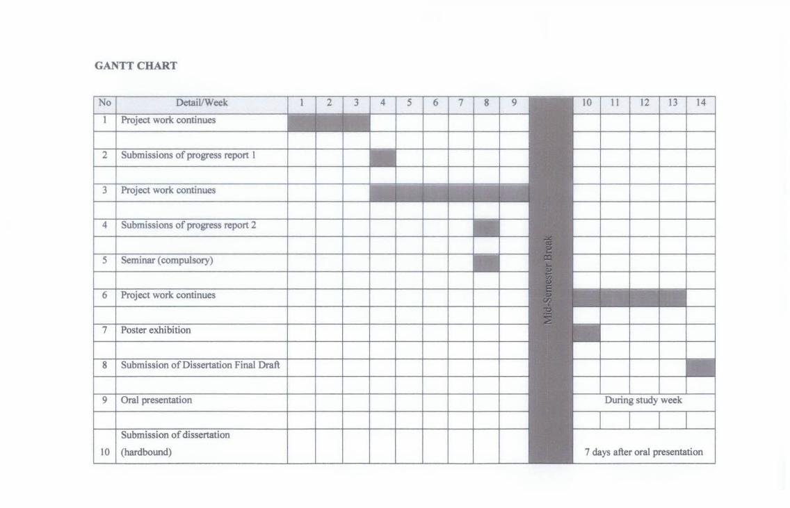
GANTT CHART
No I Detail/Week 4 5 6 7 8 9 10 11 12 13 14
Project work continues
2 I Submissions of progress report 1
3 I Project work continues
4 I Submissions of progress report 2
5 I Seminar (compulsory)
£ect work continues
ter
8 Submission of Dissertation Final Draft
9 Oral presentation
Submission of
10 I (hardbound) 7 days after oral presentation

References
Bolton, W. (2003). Mechatronics, electronic control systems in mechanical and
electrical engineering, third edition. England, UK: Pearson Prentice Hall.
Chart, C., Kersha, J.F. & Ed, D. (2007). Classroom manual:
Automotive steering, suspension, and wheel alignment: third edition. Harlow,
UK: Pearson Prentice-Hall.
Gillespie, T.D. (1992). Fundamentals of vehicle dynamics. Washington, USA: SAE
International .
Minh, V.T. (2008). Advance vehicle dynamics. Kuala Lumpur, MY: Petronas University
of Technology Press.
Prof. Messner, B. (1997). PID tutorial. Retrieved February 10, 2009, from
Control tutorials for matlab Web
site:http://www.engin.umich.edu/group/ctm/PID/PID.html
site: opus.bath.ac.uk/1882/