designing a user interface for the pico image...
TRANSCRIPT

15078
Examensarbete 15 hpDecember 2015
Designing a User Interface for the Pico Image Processor
Staffan Edström
Institutionen för informationsteknologiDepartment of Information Technology


Teknisk- naturvetenskaplig fakultet UTH-enheten Besöksadress: Ångströmlaboratoriet Lägerhyddsvägen 1 Hus 4, Plan 0 Postadress: Box 536 751 21 Uppsala Telefon: 018 – 471 30 03 Telefax: 018 – 471 30 00 Hemsida: http://www.teknat.uu.se/student
Abstract
Designing a User Interface for the Pico ImageProcessor
Staffan Edström
The Pico image editor was developed at Bell Labs in 1984. The program includes asmall pseudo-mathematical image transformation language. Although beingwell-designed, the functionality of the program does not meet modern standards. Itonly works on greyscale images and it runs in a command-line interface. To make itwork on modern digital images the program must be extended with color supportand additional features. The task also includes finding a solution for incorporating thefunctionality of the program and displaying the images in a modern graphical userinterface where usability and effectiveness are prioritised. By using principles of imageprocessing theory and graphical user interface design theory an extended version ofthe Pico program and a graphical user interface was created. It was built as a webbrowser application using HTML, CSS and JavaScript. The dynamic parts of theprototype program were built using the Nodejs framework. It has extendedfunctionality combined with an easy to use interface. The program can be used foreducational purposes to demonstrate the principles of image processing and as acreative tool for generating images and creating art.
Tryckt av: Reprocentralen ITC15078Examinator: Olle GällmoÄmnesgranskare: Stefan SeipelHandledare: Lars Oestreicher


Contents
1 Introduction 7
1.1 Problem Description . . . . . . . . . . . . . . . . . . . . . . . 71.2 Limitations . . . . . . . . . . . . . . . . . . . . . . . . . . . . 8
2 Background 8
2.1 Digital Image Manipulation . . . . . . . . . . . . . . . . . . . 82.2 The Structure of Pico . . . . . . . . . . . . . . . . . . . . . . . 10
3 Theory 12
3.1 Image Transformation Languages . . . . . . . . . . . . . . . . 123.2 The Pico Language . . . . . . . . . . . . . . . . . . . . . . . . 133.3 Augmentations to the Pico Language . . . . . . . . . . . . . . 153.4 Graphical User Interface . . . . . . . . . . . . . . . . . . . . . 16
3.4.1 Design Principles and Guidelines . . . . . . . . . . . . 173.4.2 Practical Guidelines for Website Design . . . . . . . . . 18
4 Design 19
4.1 Choice of Tools and Frameworks . . . . . . . . . . . . . . . . . 194.2 Applying Design Principles and Guidelines . . . . . . . . . . . 204.3 Extension for colour support . . . . . . . . . . . . . . . . . . . 22
5 Implementation 22
5.1 Extending the Pico Language . . . . . . . . . . . . . . . . . . 225.2 Graphical User Interface . . . . . . . . . . . . . . . . . . . . . 24
5.2.1 Drawing . . . . . . . . . . . . . . . . . . . . . . . . . . 245.2.2 Controllers . . . . . . . . . . . . . . . . . . . . . . . . . 275.2.3 Handling colours . . . . . . . . . . . . . . . . . . . . . 27
5.3 Nodejs server . . . . . . . . . . . . . . . . . . . . . . . . . . . 29
6 Discussion and Conclusion 31
6.1 Future work . . . . . . . . . . . . . . . . . . . . . . . . . . . . 33
7 Bibliography 34
5

1 Introduction
Pico is a program originally written in C and was developed in 1984 atBell Labs [1]. It is a relatively small program that allows you to manipulatepictures by writing pseudo-mathematical expressions that are interpreted andapplied to every pixel of the image according to the specified formula. Theexpressions are written in the Pico language which was specifically createdfor image editing purposes and is made out of a set of predefined keywordsand grammar rules.
The current version of the pico program has a command-line interface andcan run on any machine that can run C. It works on raw images wherethe data structure is an array of bytes representing each pixel value. Theoriginal program can perform both geometric image transformation as wellas brightness transformations.
Although Pico has a very expressive language, the features of the programdo not meet modern standards. It was purposely created for processing blackand white images and you can only do geometric transformations based onCartesian coordinates.
The aim of this project is to explore the potential of the program with anextension of the Pico language with support for polar coordinates, supportcolour pictures and also integrate it with a graphical user interface witha display routine to make it more compatible with pictures and usabilitystandards that is expected from a modern application.
1.1 Problem Description
The task consists of two main parts. The first is to find a technical solutionfor modernising the program by extending the image transformation languagewith more features to make it compatible with colour images instead of onlygrayscale images. The original program handles images where each pixelis represented by one byte, but to work with colours each pixel must berepresented by multiple bytes. This adds more dimensions to work with inthe program. As part of extending the features of the program, the languageshould support geometric transformations based on polar coordinates.
7
The second part of the task is to find a solution to displaying and handling theimage manipulation functions in a graphical user interface. It should be madeto support a range of image manipulation functions, including rotations,geometrical transformations and colour conversions. A big challenge liesin maintaining the flexibility of the program and creating a graphical userinterface that is not restricting the user.
1.2 Limitations
For this project only a prototype application will be made for the purposeof exploring the possibilities within the fields of graphical user interface andimage processing.
Image formats that use compression will not be supported, such as thecommonly used .png or .jpg file formats. The images will be saved in anuncompressed raw format.
2 Background
2.1 Digital Image Manipulation
Image manipulation is a part of the field of digital image processing [2].Historically, pictures were manipulated even before computers could do it.It was done manually by using various tools to manipulate physical photos byadding or removing colours, cut and paste pieces or blurring them. There aremany advantages of digital editing. Among them, the process is reversibleand storing it digitally allows easier distribution. In addition the differentpossibilities of manipulations are endless because of the calculating powersof computers.
The reasons for manipulating images are many. Image manipulation can bedivided into technical and creative retouching. Creative retouching is usedas an art form, it is a way of creating art with using computers as tools.Perception is not objective, so image manipulation can be an exciting wayto express more clearly what an artist wants to show. Nowadays most social
8
media websites encourage the use of filters to make photos more attractiveand anyone with a smartphone can easily alter the apparent reality of a photoin ways that were not possible before the introduction of computers.
Technical retouching is the other type of manipulating photos. Functionsbelonging to this category are for restoration or enhancement of pictures,such as adjusting brightness, contrast and sharpness until the desired resultis achieved. It is the job of the programmers to make it possible for users tocreate the desired outcome. Tools for doing this include well-known programssuch as MatLAB [3] and Adobe Photoshop [4]. Pico is one of many alternativetools for manipulating photos.
9
2.2 The Structure of Pico
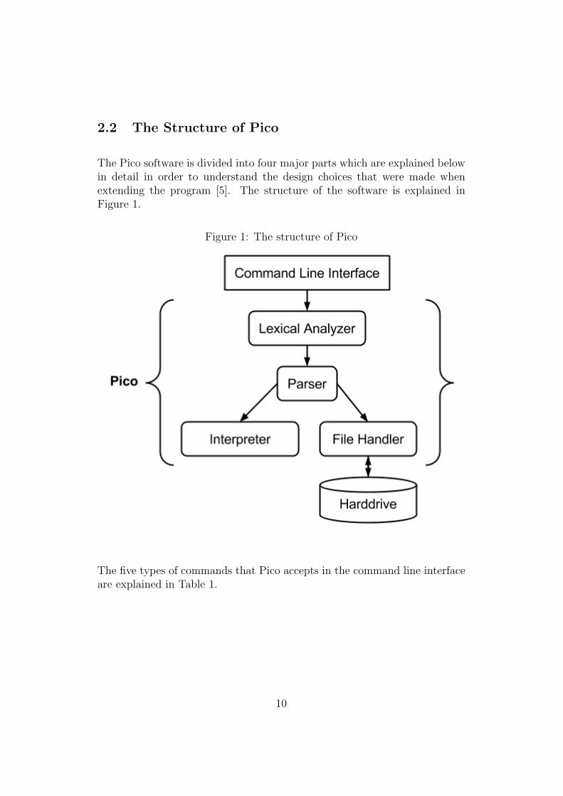
The Pico software is divided into four major parts which are explained belowin detail in order to understand the design choices that were made whenextending the program [5]. The structure of the software is explained inFigure 1.
Figure 1: The structure of Pico
The five types of commands that Pico accepts in the command line interfaceare explained in Table 1.
10
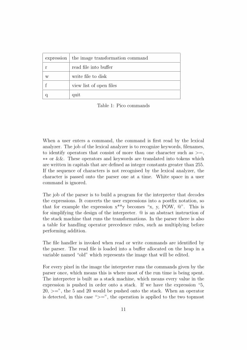
expression the image transformation command
r read file into buffer
w write file to disk
f view list of open files
q quit
Table 1: Pico commands
When a user enters a command, the command is first read by the lexicalanalyzer. The job of the lexical analyzer is to recognize keywords, filenames,to identify operators that consist of more than one character such as >=,∗∗ or &&. These operators and keywords are translated into tokens whichare written in capitals that are defined as integer constants greater than 255.If the sequence of characters is not recognised by the lexical analyzer, thecharacter is passed onto the parser one at a time. White space in a usercommand is ignored.
The job of the parser is to build a program for the interpreter that decodesthe expressions. It converts the user expressions into a postfix notation, sothat for example the expression x**y becomes “x, y, POW, @”. This isfor simplifying the design of the interpreter. @ is an abstract instruction ofthe stack machine that runs the transformations. In the parser there is alsoa table for handling operator precedence rules, such as multiplying beforeperforming addition.
The file handler is invoked when read or write commands are identified bythe parser. The read file is loaded into a buffer allocated on the heap in avariable named “old” which represents the image that will be edited.
For every pixel in the image the interpreter runs the commands given by theparser once, which means this is where most of the run time is being spent.The interpreter is built as a stack machine, which means every value in theexpression is pushed in order onto a stack. If we have the expression “5,20, >=”, the 5 and 20 would be pushed onto the stack. When an operatoris detected, in this case “>=”, the operation is applied to the two topmost
11

values of the stack and the result is pushed back to the stack.
3 Theory
3.1 Image Transformation Languages
Images are represented on a computer as a two-dimensional array where eachelement holds the pixel value [6]. Many image processing programs thatexist today allow the user to define functions themselves by using the scriptlanguage of the specific program. Since we are essentially only changing thevalues of pixels which are represented by bytes, most modern programminglanguages can be used to manipulate images such as C [7], Matlab or Java[8]. People have attempted to create more compact languages which donot require the user to have any prior knowledge of C or Java for example.Instead of requiring knowledge of language specific syntax and libraries, theselanguages are created specifically for image transformation. One of the mostwell known is ImageJ:s macro language [9]. ImageJ is an open source imageprocessing program written in Java and it was mainly designed for scientificimages. It is also used for educational purposes because of its ability toeasily define the user’s own functions and plugins in a variety of languages,including their own macro language.
Other image processing programs, such as GIMP [10] and Adobe Photoshopalso allow the user to write their own functions and plugins in C and C++[11] respectively [12]. The advantage of writing functions in a completeprogramming language is mainly the flexibility. An image manipulationlanguage such as Pico has a limited functionality in comparison to a completeprogramming language and is therefore not commonly used. Another reasonwhy these languages are not widely used is because of the extensive array ofpredefined functions found in graphical user interfaces of the modern imageeditors as found in GIMP and Adobe Photoshop. At the time Pico was made,languages such as Java which had better code readability and were easier toprogram were not yet developed. The developers of Pico then decided tocreate a minimalistic image manipulation language to allow people who didnot have prior knowledge in computer programming to use. The pros of suchimage manipulation languages are they are generally shorter and easier tolearn because of its simpler syntax.
12

3.2 The Pico Language
To understand how to extend the Pico language and also how to operateit, an introduction to the Pico language is required. It was designed to belogical and no previous knowledge of C programming is required.
In a computer an image is represented as a two-dimensional array of cellswhere each cell has three attributes, namely the pixel value, the X-positionand the Y-position. The Pico language currently supports referring to eachpixel by position on the Cartesian coordinate system where the origin (0,0)is at the upper left corner of the image. The value of the pixel is representedas a binary value in a 8-bit grayscale that represents the brightness withina range between 0 and 255 where a low value is darker and a high value isbrighter. The brightness of a pixel is stored as an unsigned integer in onebyte, which means 256 values can be stored in it. The symbols and featuresin the Pico language are explained below.
Two very important symbols in the language are the variables “old” and“new” which are buffers which is where the edited images are stored. Whenthe program is started, the “old” variable always contains a two-dimensionalarray where each element is 255, which means it is a completely black image.When a transformation is performed, the “old” variable contains the lasttransformation performed.
When a picture is loaded into the edit buffer it can be referred to using thename of the file. A file named “baboon” would simply be referred to as“baboon” in a transformation expression. As an example, a basic expressionfor inverting the colours of the picture named “baboon” would be:
new[x, y] = -baboon[x, y]
The result of the transformation is shown in Figure 2. “New” refers to thenew picture and ”new[x, y]” is the position of every pixel from origin [0,0] corresponding to the width and height of the picture, that is referred toas [X, Y]. The above expression therefore means that every pixel value onposition [x, y] will be subtracted by the pixel value of the baboon picture.If the pixel at the position baboon[5, 1] has the value 255, which means itis white, it will subtract 255 from the pixel value of new[5, 1]. The image“new“ is by default a completely black picture where each pixel has value 0,therefore the pixel value of new[5, 1] will become (0 - 255) % 255 = 0 which
13
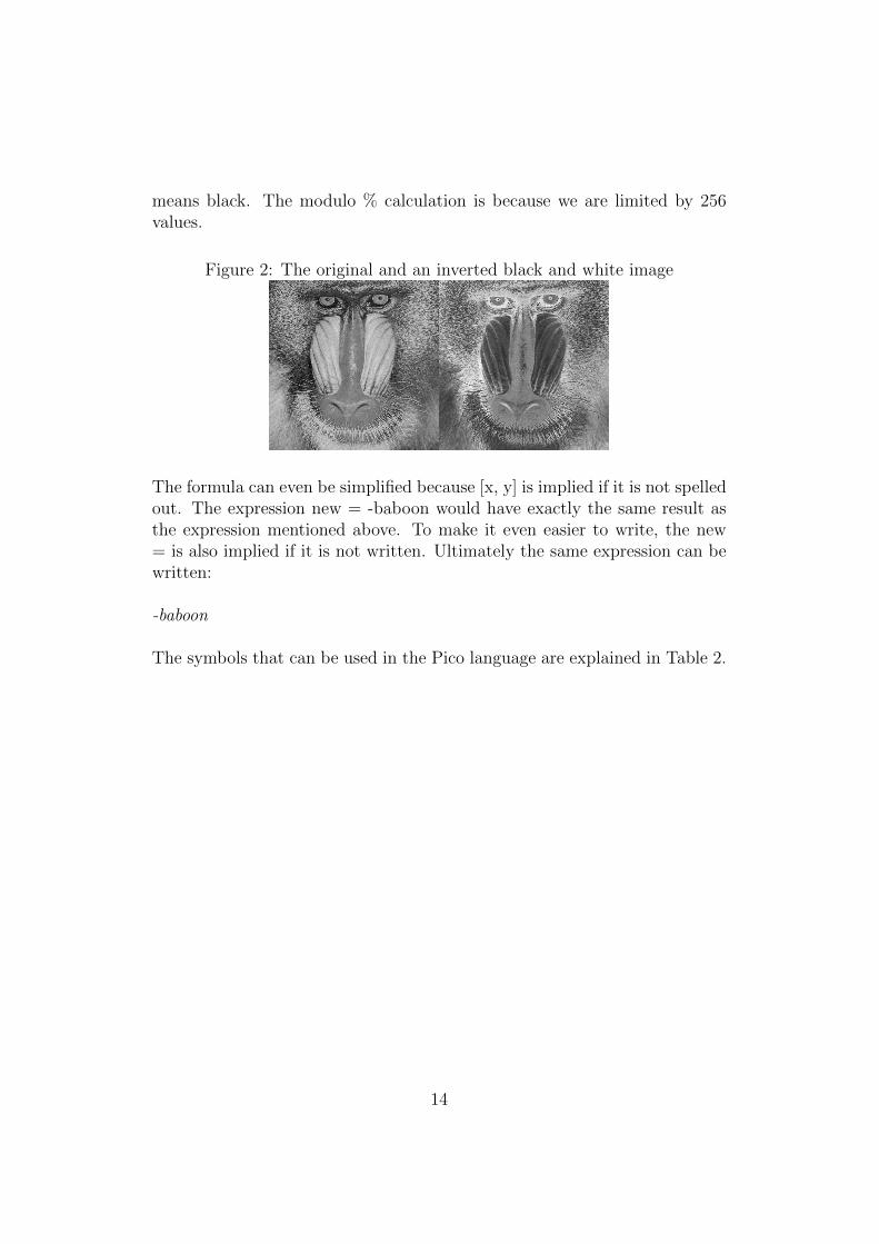
means black. The modulo % calculation is because we are limited by 256values.
Figure 2: The original and an inverted black and white image
The formula can even be simplified because [x, y] is implied if it is not spelledout. The expression new = -baboon would have exactly the same result asthe expression mentioned above. To make it even easier to write, the new= is also implied if it is not written. Ultimately the same expression can bewritten:
-baboon
The symbols that can be used in the Pico language are explained in Table 2.
14

X width of the picture
Y height of the picture
x horizontal position of a pixel in the picturebetween 0 and X-1
y vertical position of a pixel in the picture between0 and Y-1
mypicture variable referring to an image file named mypictureloaded into the program
- subtraction
+ addition
** left hand value to the power of right hand value
( ) parentheses can be used to modify normal order ofoperations
condition?iftrue:iffalse conditional expression
Table 2: Pico language symbols
3.3 Augmentations to the Pico Language
There are many ways of representing the pixel positions of an image. Above,only the Cartesian coordinate system was used where x and y were the onlysymbols that located the pixels. Another way of representing an image is byusing the polar coordinate system [13]. Unlike from the Cartesian coordinatesystem [14], the reference point of the positioning is in the center of the image.When we use polar coordinates the origin is instead called the pole. In orderto use polar coordinates it is required to introduce two new symbols r anda into the language. In addition, two additional variables that will becomepractical are shorthand values for the max radius and angle of the currentimage, represented by R and A respectively. The symbols are explained inTable 3.
15
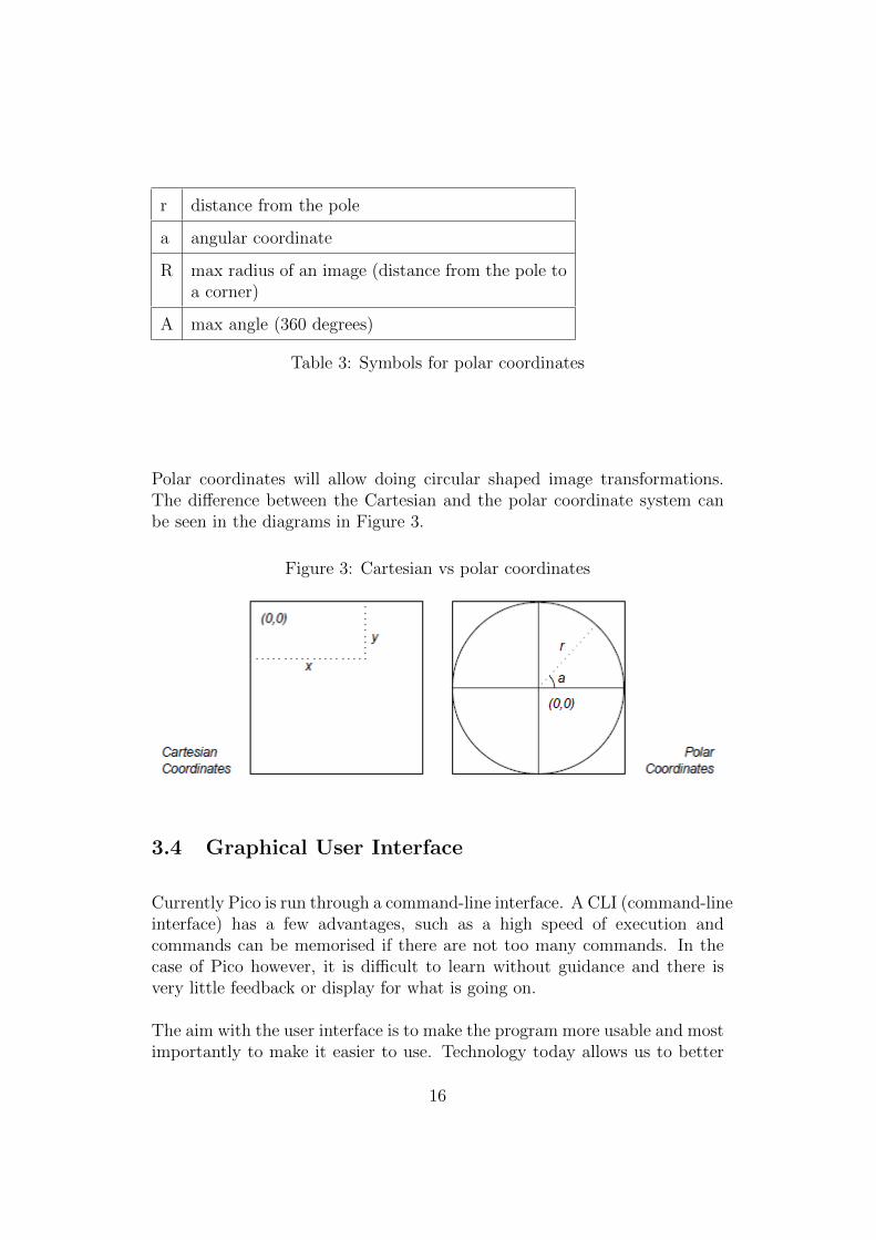
r distance from the pole
a angular coordinate
R max radius of an image (distance from the pole toa corner)
A max angle (360 degrees)
Table 3: Symbols for polar coordinates
Polar coordinates will allow doing circular shaped image transformations.The difference between the Cartesian and the polar coordinate system canbe seen in the diagrams in Figure 3.
Figure 3: Cartesian vs polar coordinates
3.4 Graphical User Interface
Currently Pico is run through a command-line interface. A CLI (command-lineinterface) has a few advantages, such as a high speed of execution andcommands can be memorised if there are not too many commands. In thecase of Pico however, it is difficult to learn without guidance and there isvery little feedback or display for what is going on.
The aim with the user interface is to make the program more usable and mostimportantly to make it easier to use. Technology today allows us to better
16

interact with people than ever before and therefore it is necessary to havea human-centered perspective when designing the user interface. Instead ofthinking about what technology can do we should rather think about whatpeople want to do with it. To make it human-centered we need to identifythe possible users of this program. It should be available for anyone to use,but catered to technical people who want to explore the possibilities of thePico language.
Apart from there being many resources in literature on the subject of howto design user interfaces, there are also many companies such as Apple andMicrosoft that provide their own design guidelines for applications made tosuit the standards of their operating systems [15]. Although these companiestoday have a huge influence on how user interfaces are designed, the applicationbeing made is supposedly meant to be platform independent.
3.4.1 Design Principles and Guidelines
To ensure a human-centered design, some universal interface design principlesthat exist can be applied. Donald Norman’s design principles for usability[16] are of great help when designing a user interface and can be during thedesign stage to stimulate ideas and can also act as a check list. According toNorman, the three main features a user interface should have is for users tolearn it easily, should be effective and accomodating. These three categoriescan then be further divided into 12 specific principles, which together guidesthe designer into creating a more human-centered user interface. Out ofthese, the principles that are highly relevant to this type of application arethe following:
• High visibility to make sure people can see what functions are availableand what the system is currently doing
• Consistency in the design with regards of similar systems people areused to work with
• Affordance, to make things look like what they are made for
• Feedback is important so the user knows when he has done somethingwrong and also let the user view the result of when he did it correctly
• Recovery from mistakes and errors should be quick and efficient
17

• Flexibility to allow users of different levels of experience to use andbecome interested in the system
• Style should be attractive and not disturbing from the task
3.4.2 Practical Guidelines for Website Design
David Benyon also provides more specific guidelines for website design thatderive from the understanding of the psychology of people. For example,memory an important factor and a user should always see what is happening.Perhaps the user takes a break and continues after a while or has short-termmemory. Then it is important to see what stage the application is in. Humanattention also has its limitations and according to experiments people do notprefer lists and menus longer than 7 items, although even lower is better. Itis claimed that if a person start going down a list of more than 7 items, theperson will have forgotten what is at the top. Instead of making long liststhe list items should be grouped into sub-menus.
The use of colours is also important and there should not be too many usedin the interface. According to western colour conventions, we see greys, whiteand blue as neutral colours. Most colours represent something to people andwe should avoid choosing a colour that stimulates the mind in an unwantedway that is not related to the task.
Error messages can ruin the user experience if they are aggressive or lackclarity. The messages should instead be polite and there should not be anyabrupt interruptions. Also instead of blaming the user for doing wrong,the system should take the blame for the errors. For example we read“unrecognized command” in a different way than “illegal command”. If theerrors are shown with colour shifts or flashes, the colour should be chosenappropriately.
18

4 Design
4.1 Choice of Tools and Frameworks
Web applications are traditionally less responsive than applications designedfor a desktop environment, mainly because of network communication beinga bottleneck [17]. The advantages of web applications however are many, asit can be used to relieve the client from running CPU-heavy processing andthe application can be accessed anywhere on any platform. The choice oftools and frameworks for this project will therefore be languages chosen forcreating the most flexible web applications. The most convenient languagefor web applications in use today is JavaScript [18]. The platform that willbe used is Nodejs because of its excellent abilities to create an asynchronouscommunication between the server and the client application [19]. Anotherreason to choose Nodejs above other programming frameworks is it is convenientto write the server side logic in the same programming language as the client.
As for the drawing of the images the HTML5 Canvas [20] element will beused. The file format of the images Pico produces is not a standardised fileformat that is in use today, but is closely related to the .bmp file format, asit is simply an array of bytes representing each pixel (also called pixmap orbitmap). Using the HTML5 Canvas element will make it easy to draw andupdating images without updating the page. Receiving data and showing itto the client will be done using AJAX (Asynchronous Javascript And XML)[21]. The complete ecosystem is explained below in Figure 4.
19

Figure 4: Drawing of the complete system
4.2 Applying Design Principles and Guidelines
The first step is to create a layout of the user interface to fulfil the necessaryrequirements. The requirements are to view the images and to be able toedit them. They should fit in one page to give good visibility of what is goingon and clearly show the array of functions. A draft layout of the applicationis shown in Figure 5.
20

Figure 5: Sketch of GUI layout design
There will be a container surrounding the elements to show that they belongtogether. The background colour will be something neutral such as a lightgrey so it does not affect how the image is being perceived. The image willbe the biggest sized element of the page to show that it is the most centralpart of the application.
When it comes to the functionality of the program, a list of predefined Picoexpressions will be provided. Following the ideas of David Benyon, the lengthof the list will not exceed 7 items. When a function is selected, the imagewill be transformed accordingly. The response should be immediate to let theuser know what is happening. When the user selects a function, the formulafor the function will appear in the formula input field. This feature keepsthe flexibility of the program and allows the user to tweak the predefinedformula for experimentation, or create their own formulas. If the formulainput field is changed, the user will have to confirm the change by pressingthe “Draw” button. To make it consistent with what people expect whenwriting formulas, the font style in the formula input field will be monospaced.
If the user has written an illegal expression that cannot be processed byPico, no new picture will be drawn, but instead an error will be passed on.There will be no extra step or click to recover from an error. It should beclear that something went wrong, so the error will be shown in a polite and
21

undisturbing way by making the formula input field blink in a red colour.A fading pop-up text displaying “unrecognized command” will also show upnext to the input field to show what went wrong.
4.3 Extension for colour support
To edit multiple colours there will be an optional feature that can be toggledon and off by checking a “Multicolor mode” checkbox. When in multicolourmode the user will be able to write formulas for red, green and blue separately.Instead of one formula field, two additional formula fields will appear. WhileMulticolor mode is on, the Pico program will run once for each formula andsave the image data for red, green and blue as separate files. This solutionwill allow greater readability and expand editing capabilities of the imageson all colour levels while still using the normal Pico language. The design ofthe formula fields in multicolor mode is shown in Figure 6.
Figure 6: RGB formula fields
5 Implementation
5.1 Extending the Pico Language
The following code snippets are the implementations done in regards toextending the Pico language in the code written in C.
The shorthand values R and A representing the max radius and angle are
22
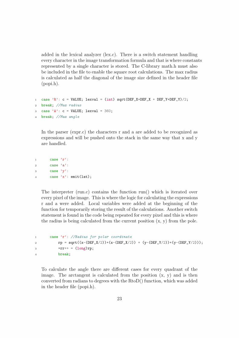
added in the lexical analyzer (lex.c). There is a switch statement handlingevery character in the image transformation formula and that is where constantsrepresented by a single character is stored. The C-library math.h must alsobe included in the file to enable the square root calculations. The max radiusis calculated as half the diagonal of the image size defined in the header file(popi.h).
1 case ’R’: c = VALUE; lexval = (int) sqrt(DEF_X*DEF_X + DEF_Y*DEF_Y)/2;
2 break; //Max radius
3 case ’A’: c = VALUE; lexval = 360;
4 break; //Max angle
In the parser (expr.c) the characters r and a are added to be recognized asexpressions and will be pushed onto the stack in the same way that x and yare handled.
1 case ’r’:
2 case ’a’:
3 case ’y’:
4 case ’x’: emit(lat);
The interpreter (run.c) contains the function run() which is iterated overevery pixel of the image. This is where the logic for calculating the expressionsr and a were added. Local variables were added at the beginning of thefunction for temporarily storing the result of the calculations. Another switchstatement is found in the code being repeated for every pixel and this is wherethe radius is being calculated from the current position (x, y) from the pole.
1 case ’r’: //Radius for polar coordinate
2 rp = sqrt((x-(DEF_X/2))*(x-(DEF_X/2)) + (y-(DEF_Y/2))*(y-(DEF_Y/2)));
3 *rr++ = (long)rp;
4 break;
To calculate the angle there are different cases for every quadrant of theimage. The arctangent is calculated from the position (x, y) and is thenconverted from radians to degrees with the RtoD() function, which was addedin the header file (popi.h).
23
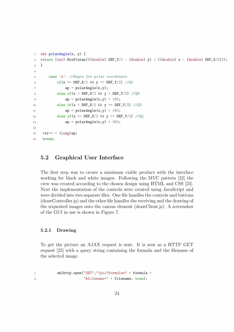
1 int polarAngle(x, y) {
2 return (int) RtoD(atan(((double) DEF_Y/2 - (double) y) / ((double) x - (double) DEF_X/2)));
3 }
4
5 case ’a’: //Angle for polar coordinate
6 if(x >= DEF_X/2 && y <= DEF_Y/2) //Q1
7 ap = polarAngle(x,y);
8 else if(x < DEF_X/2 && y < DEF_Y/2) //Q2
9 ap = polarAngle(x,y) + 180;
10 else if(x < DEF_X/2 && y >= DEF_Y/2) //Q3
11 ap = polarAngle(x,y) + 180;
12 else if(x >= DEF_X/2 && y >= DEF_Y/2) //Q4
13 ap = polarAngle(x,y) + 360;
14
15 *rr++ = (long)ap;
16 break;
5.2 Graphical User Interface
The first step was to create a minimum viable product with the interfaceworking for black and white images. Following the MVC pattern [22] theview was created according to the chosen design using HTML and CSS [23].Next the implementation of the controls were created using JavaScript andwere divided into two separate files. One file handles the controls and buttons(drawController.js) and the other file handles the receiving and the drawing ofthe requested images onto the canvas element (drawClient.js). A screenshotof the GUI in use is shown in Figure 7.
5.2.1 Drawing
To get the picture an AJAX request is sent. It is sent as a HTTP GETrequest [25] with a query string containing the formula and the filename ofthe selected image.
1 xmlhttp.open("GET","/pic?formula=" + formula +
2 "&filename=" + filename, true);
24

Figure 7: The GUI with an example of an image generated using the program
25

If the response string starts with “error” the error is shown to the client andthe formula field flashes with a jQuery [24] effect. The error message is alsowritten in the web browser console. If no error is detected in the receivedbyte array the drawRaw(data) function is run. Since there is no metadatafor width and height of the image, it is implemented to work for squareimages only. The values of the byte array are between 0 and 255 and areextracted from the byte array using the JavaScript function charCodeAt()which returns the value of the byte. The value is then converted into ahexadecimal value and concatenated with itself three times to create a hexadecimalcolor representation. For a black and white image the values for red, greenand blue are always equal. The colour is then applied to the canvas draw fillstyle and a pixel is then filled with the colour. This process repeats for everypixel (x,y) of the image. Below is the code for grayscale images.
1 var drawRaw = function(data){
2
3 var canvas = document.getElementById("canvas");
4 var ctx = canvas.getContext("2d");
5 var bytes = data;
6 var size = Math.sqrt(bytes_r.length);
7 canvas.width=size;
8 canvas.height=size;
9 var x = 0;
10 var y = 0;
11
12 while(bytes_r.length !== 0) {
13 if(x >= size) {
14 i = 0;
15 x = 0;
16 y = y + 1;
17 }
18
19 c = bytes.charCodeAt(0);
20 bytes = bytes.substring(1);
21
22 var colour = "#"+byteToHex(c)+byteToHex(c)+byteToHex(c);
23 ctx.fillStyle = colour;
24 ctx.fillRect(x, y, 1, 1);
25
26 x = x + 1;
26

27 }
28 }
5.2.2 Controllers
A global variable named selectedPic is an important part of my implementation.As a default it is set as the first image in the list of images. When anotherimage is selected from the list, the variable is updated as well as the formulasthat depend on the name of the image.
Every formula that is created is a JavaScript object containing a name anda formula represented as strings. The formulas are then very easy to pushonto the list of predefined functions. The list is then cleared and updatedevery time with the newly selected image.
1 var picoFormula = function(name, formula) {
2 this.name = name;
3 this.formula = formula;
4 return this;
5 };
6
7 var updateFunctions = function() {
8 functions = [];
9 functions.push(new picoFormula("None", selectedPic));
10 functions.push(new picoFormula("Spin", selectedPic+"[((r*r)/R)/2, y]"));
11 };
When a formula is selected the formula input field updates and shows theselected formula, this is so you can see it and execute by pressing Enter orclicking on the Draw button.
5.2.3 Handling colours
The initial idea was to change the Pico language for handling colors. The ideawas dismissed because the formulas became too complex and it would ruinthe readability which is one of the strengths of the Pico language. Instead
27

the solution was to have a formula for every colour. This was added whenthere was already a working version for grayscale images, so a check boxwas added to toggle between color mode and normal mode with a smoothanimation between them using jQuery. When a formula is selected in the listof formulas, all three input fields update with the selected formula as seen inFigure 8.
1 var toggleMulticolorMode = function() {
2 var selectFunctionValue = (document.getElementsByName("selectFunction")[0]).value;
3 var addButton = function(div) {
4 div.innerHTML += ’<button id="drawBtn" class="drawButton" onClick="getPic()">
5 Draw
6 </button>’;
7 }
8
9 var div = document.getElementById("formulaForm");
10 if(document.getElementById("multicolor").checked) {
11 var currentFormula = document.getElementById("formula").value;
12 $("#formulaForm").slideUp(10);
13 $("#formulaForm").slideDown(500);
14
15 //Checked box, make three formula forms
16 div.innerHTML = ’R <input type="text" id="formula_r" class="formulaField"><br>’
17 + ’G <input type="text" id="formula_g" class="formulaField"><br>’
18 + ’B <input type="text" id="formula_b" class="formulaField">’;
19 addButton(div);
20 updateFormulaFields(currentFormula);
21 } else {
22 $("#formulaForm").slideUp(10);
23 $("#formulaForm").slideDown(500);
24 //Unchecked, make only one formula form
25 div.innerHTML = ’<input type="text" id="formula" class="formulaField"><br>’;
26 addButton(div);
27 updateFormulaFields(selectFunctionValue);
28 }
29 }
When requesting to draw an image in colour mode, the three formulas aresent together and are added into a list in order. The formulas are then sent
28

in a loop with one AJAX-request at a time, so that the error can be traced toany invalid formula using the same method as for a black and white image.The output file which is always called pico out is also extended with suffixesr, g and b.
Figure 8: Multicolor mode example with no changes made on red color levels
5.3 Nodejs server
The server for the program needed to handle two kinds of HTTP requests.One to load the files necessary for the GUI and the other for handling theAJAX request. When a HTTP request url starts with the string “/pic” theserver expects a formula, a filename and a color suffix to be included in thequery string. Pico is then started as a child process and the commands arewritten to Pico through its command line interface (stdin). In the callbackfunction the output file or an error is returned to the client. Note that theNodejs uses non-blocking IO and the callback function in this case is triggeredwhen the Pico process terminates. Below is a code snippet showing how animage request is handled by the server.
1 if((req.url).lastIndexOf("/pic", 0) === 0) {
2 var queryData = url.parse(req.url, true).query;
3 var formula = queryData.formula;
29
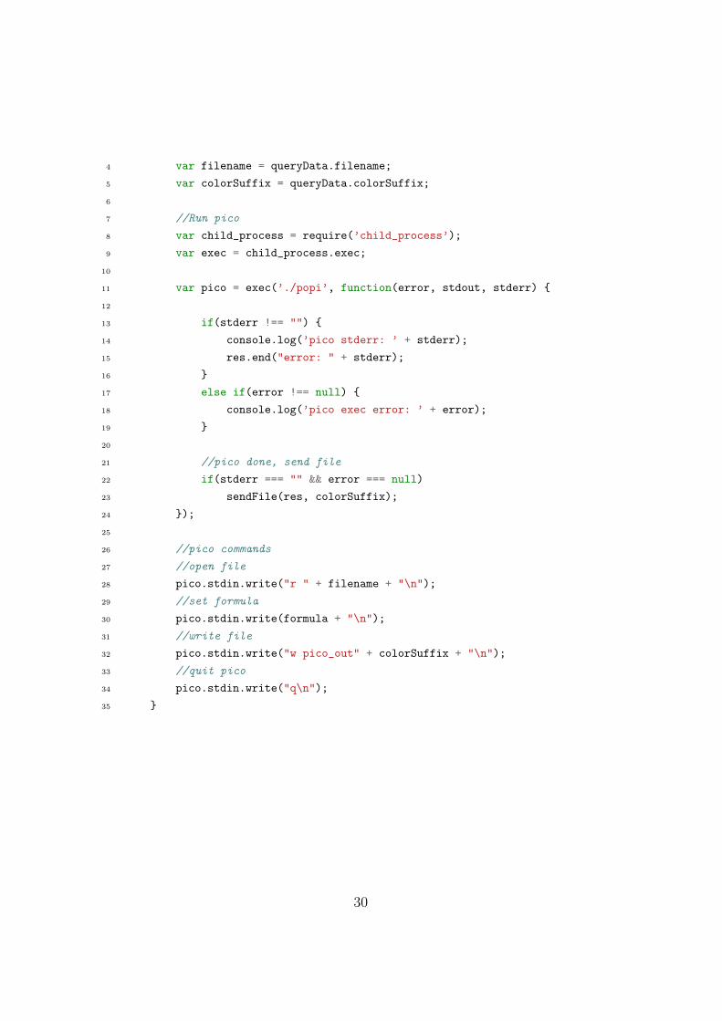
4 var filename = queryData.filename;
5 var colorSuffix = queryData.colorSuffix;
6
7 //Run pico
8 var child_process = require(’child_process’);
9 var exec = child_process.exec;
10
11 var pico = exec(’./popi’, function(error, stdout, stderr) {
12
13 if(stderr !== "") {
14 console.log(’pico stderr: ’ + stderr);
15 res.end("error: " + stderr);
16 }
17 else if(error !== null) {
18 console.log(’pico exec error: ’ + error);
19 }
20
21 //pico done, send file
22 if(stderr === "" && error === null)
23 sendFile(res, colorSuffix);
24 });
25
26 //pico commands
27 //open file
28 pico.stdin.write("r " + filename + "\n");
29 //set formula
30 pico.stdin.write(formula + "\n");
31 //write file
32 pico.stdin.write("w pico_out" + colorSuffix + "\n");
33 //quit pico
34 pico.stdin.write("q\n");
35 }
30

6 Discussion and Conclusion
My contributions to this project are the following:
• A web-browser user interface based on JavaScript with support for arange of image transformation functions and colour image editing
• An extension of the Pico image transformation language to supportimage transformations based on polar coordinates
• A server side application based on the Nodejs framework for handlingthe Pico program and asynchronous communication with the client
• An auxiliary program in Nodejs for converting both greyscale andcolour .png and .jpg format images into raw file format
The prototype program proved to be an efficient and a user-friendly way ofgenerating and manipulating images. The ability to generate images is in myopinion the most interesting feature of the program, and incorporating colorsadds more dimensions to work with. What makes the extended programspecial among the wide range of image editing software available today suchas MatLab or ImageJ is its simple one row formulas and the addition ofa unique way of handling colours in a way that is easy to understand. Inaddition, the fact that it can be run in the web browser makes it platformindependent and does not require any installed software.
When comparing the language of the program to other image transformationlanguages some pros and cons are revealed. The major advantage of theprototype program is that it is easier to use and more readable because onlyone line at a time can be written, but that also means it is less complextransformations. Another downside with the current implementation is thatyou can not use floating point numbers in the formulas. The range offunctionality in image editors such as MatLab and ImageJ is much widerand these programs are better suited for image analysis purposes, but theprograms have a steeper learning curve for a new user. Compared to aprogram that mostly relies on graphical user interface functions such asGIMP and Photoshop, where the functionality is deeply embedded intomenus, sub menus and slide bars, script based image editing gives the usera hands-on experience on a pixel-level. What the script based image editors
31

(including the prototype program) have in common is they minimise theabstract layer between the user and the image processing functions, andbecome useful tools to give an introduction to image processing. Thereforein my view the prototype program can be used in education to show howimage processing works in a way that is easier to comprehend than with thecompared programs. It an also be used as a creative tool for any user who iscomfortable writing pseudo-mathematical formulas but not necessarily haveprevious programming experience.
Initially the Pico program was difficult to work with because of the compactcoding style they used when it was originally created. I think the readabilityof the code was not one of their main priorities when it was written, butonce I got a grasp of how the modules and the code worked it proved to berelatively easy to add new variables and new functionality.
In this implementation the colours are not related to each other. A colourvalue cannot be a function of another colour (an example is if we wanted thered colour levels to be half the value of green colour levels). This could havebeen done if the colours were stored in the same file. To do this would requirea major reconstruction of Pico, a reconstruction too big for the scope of thisproject. On the downside, incorporating the feature into the Pico languagewould add a level of complexity and thus making the formulas less readable.
When designing a graphical user interface I knew that some of the functionalityneeded to be compromised. To include more complex functions, the userinterface becomes more complex too. When it comes to a solution forhandling multiple images the flexibility had to be compromised and functionalitysupporting it was not included. A solution could be to allow multiple selectionof images and load every selected image into the program.
The design of the graphical user interface itself made the program userfriendly, aesthetically pleasing and easy to use for users without any priorexperience, and a user can learn the language just by studying the predefinedformulas. The predefined formulas were chosen to cover most of the languageand to give inspiration for further experimentation.
32

6.1 Future work
The project grew very large so I had to limit the amount of work carried outwith regards of time spent. Using the program and seeing the possibilitiesmade me want to continue developing the program, so the following are someideas of functionality to add in the future.
• Variables for random numbers would allow creating generative art
• Trigonometrical and logarithmic functions
• Support for floating point numbers in the formulas
• Save and name your own formulas
• Undo and redo functions in the user interface
• Support for multiple users by creating a unique pico out file for everyuser
33

7 Bibliography
References
[1] Holzmann, Gerard J. PICO-A Picture Editor. AT&T Technical Journal66.2 (1987): 2–13. Web.
[2] Peres, Michael R. The Focal Encyclopedia of Photography: DigitalImaging, Theory and Applications, History, and Science. Amsterdam:Elsevier/Focal Press, 2007. Print.
[3] Gilat, Amos. MATLAB: An Introduction with Applications. Hoboken,NJ: J. Wiley & Sons, 2011. Print.
[4] Galer, Mark, and Philip Andrews. Photoshop CS5: Essential Skills: AGuide to Creative Image Editing. Oxford: Focal, 2010. Print.
[5] Holzmann, Gerard J. Beyond Photography: the Digital Darkroom.Englewood Cliffs, NJ: Prentice-Hall, 1988. Print.
[6] Burger, Wilhelm, and Mark James. Burge. Principles Of Digital ImageProcessing. London: Springer, 2009. Print.
[7] Kernighan, Brian W., and Dennis M. Ritchie. The C ProgrammingLanguage. NJ: Prentice Hall, 1988. Print.
[8] Schildt, Herbert. Java: The Complete Reference, Ninth Edition. SanFrancisco: McGraw-Hill, 2014. Print.
[9] ”Introduction into Macro Programming - ImageJ”. Web, 12 Aug. 2015.http://imagej.net/Macros
[10] Lecarme, Olivier, and Karine Delvare. The Book of GIMP a CompleteGuide to Nearly Everything. San Francisco, CA: No Starch, 2013. Print.
[11] Bjarne Stroustrup. The C++ Programming Language, 4th Edition.Upper Saddle River, NJ: Addison-Wesley, 2013. Print.
[12] ”GIMP Developer Resources - How to write a GIMP plugin”. Web. 12Aug. 2015.http://developer.gimp.org/writing-a-plug-in/1/
34
[13] Stover, Christopher and Weisstein, Eric W. Polar Coordinates.MathWorld–A Wolfram Web Resource. Web, 19 Oct. 2015.http://mathworld.wolfram.com/PolarCoordinates.html
[14] Stover, Christopher and Weisstein, Eric W. Cartesian Coordinates.MathWorld–A Wolfram Web Resource. Web, 19 Oct. 2015.http://mathworld.wolfram.com/CartesianCoordinates.html
[15] “OS X Human Interface Guidelines: Designing For Yosemite”. Web. 19Oct. 2015.https://developer.apple.com/library/mac/documentation/userexperience/conceptual/osxhiguidelines/
[16] Benyon, David. Designing Interactive Systems: a Comprehensive Guideto HCI and Interaction Design. Harlow, England: Addison Wesley, 2010.Print.
[17] Lengstorf, Jason, Phil Leggetter, and Alex Newman. ”Choosing WebApps Over Native Apps”.Realtime Web Apps. Dordrecht: Springer, 2013. pp 57-64. Print.
[18] ”JavaScript — MDN”. Web, 19 Oct. 2015.https://developer.mozilla.org/en-US/docs/Web/JavaScript
[19] “About Node.Js”. Web. 19 Oct. 2015.https://nodejs.org/about/
[20] Fulton, Steve, and Jeff Fulton HTML5 Canvas. Farnham: O’Reilly,2013.
[21] Paulson, L.d. “Building Rich Web Applications with Ajax.” Computer38.10 (2005): 14–17. Web.
[22] Leff, A., and J.t. Rayfield. “Web-Application Development Usingthe Model/View/Controller Design Pattern.” Proceedings Fifth IEEEInternational Enterprise Distributed Object Computing Conference(2001). Web.
[23] “Cascading Style Sheets”. Web. 19 Oct. 2015.http://www.w3.org/Style/CSS/
[24] “jQuery”. Web. 19 Oct. 2015.https://jquery.com
35

[25] Fielding, Roy T.; Gettys, James; Mogul, Jeffrey C.; Nielsen, HenrikFrystyk; Masinter, Larry; Leach, Paul J.; Berners-Lee, Tim HypertextTransfer Protocol – HTTP/1.1. IETF. (1991) RFC 2616.
36