design windows and trade-offs for inertial fusion energy power plants farrokh najmabadi isfnt 6...
Post on 20-Dec-2015
216 views
TRANSCRIPT

Design Windows and Trade-Offs for Inertial Fusion Energy Power Plants
Farrokh Najmabadi
ISFNT 6
April 8-12, 2002 Hotel Hyatt Islandia, San Diego
Electronic copy: http://aries.ucsd.edu/najmabadi/TALKS
ARIES Web Site: http://aries.ucsd.edu/ARIES

Approach:
Six classes of target were identified. Advanced target designs from NRL (laser-driven direct drive) and LLNL (Heavy-ion-driven indirect-drive) are used as references.
To make progress, we divided the activity based on three classes of chambers:
• Dry wall chambers;
• Solid wall chambers protected with a “sacrificial zone” (such as liquid films);
• Thick liquid walls.
We research these classes of chambers in series with the entire team focusing on each.
ARIES Integrated IFE Chamber Analysis and Assessment Research Is An Exploration Study
Objectives:
Analyze & assess integrated and self-consistent IFE chamber concepts
Understand trade-offs and identify design windows for promising concepts. The research is not aimed at developing a point design.

NRL Advanced Direct-Drive Targets
DT Vapor0.3 mg/cc
DT Fuel
CH Foam + DT
1 m CH +300 Å Au
.195 cm
.150 cm
.169 cm
CH foam = 20 mg/cc
DT Vapor0.3 mg/cc
DT Fuel
CH Foam + DT
5 CH
.122 cm
.144 cm
.162 cm
CH foam = 75 mg/cc
1
10
100
1000
0 5 10 15time (ns)
laser power •NRL Direct Drive Target Gain Calculations (1-D) have been corroborated by LLNL and UW.
LLNL/LBNL HIF Target
Reference Direct and Indirect Target Designs

Analysis of design window for successful injection of direct and indirect drive targets in a gas-filled chamber (e.g., Xe) is completed. No major constraints for indirect-drive targets (Indirect-drive target is
well insulated by hohlraum materials) Narrow design window for direct-drive targets:
Target injection Design Window Naturally Leads to Certain Research Directions
(Pressure < ~50 mTorr, Wall temperature < ~700oC).
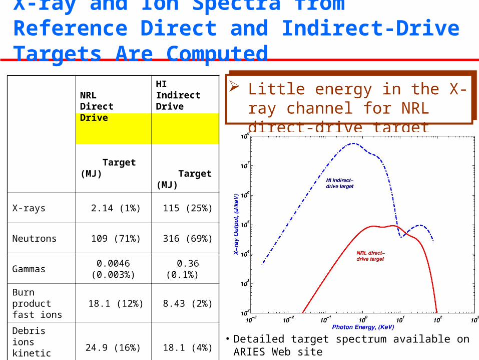
Little energy in the X-ray channel for NRL direct-drive target
NRL Direct Drive Target (MJ)
HI Indirect Drive Target (MJ)
X-rays 2.14 (1%) 115 (25%)
Neutrons 109 (71%) 316 (69%)
Gammas 0.0046 (0.003%) 0.36 (0.1%)
Burn product fast ions
18.1 (12%) 8.43 (2%)
Debris ions kinetic energy
24.9 (16%) 18.1 (4%)
Residual thermal energy
0.013 0.57
Total 154 458
• Detailed target spectrum available on ARIES Web site http://aries.ucsd.edu/ARIES/
X-ray and Ion Spectra from Reference Direct and Indirect-Drive Targets Are Computed

Ion power on chamber wall(6.5-m radius chamber in vacuum)
Photon and ion energy deposition falls by 1-2 orders of magnitude within 0.1 mm of surface
Most of heat flux due to fusion fuel and fusion products (for direct-drive).
Time of flight of ions spread the temporal profile of energy flux on the wall over several s (resulting heat fluxes are much lower than predicted previously).
Details of Target Spectra Has Strong Impact on the Thermal Response of the WallEnergy Deposition (W/m2) in C and W Slabs (NRL 154MJ Direct Drive Target)
1x10⁶
1x10⁷
1x10⁸
1x10⁹
1x10¹⁰
1x10¹¹
1x10⁻⁸ 1x10⁻⁷ 1x10⁻⁶ 1x10⁻⁵ 1x10⁻⁴ 1x10⁻³ 1x10⁻²
Debris ions,W
Fast ions, C
Photons, W
Photons, C
Fast ions, W
En
ergy
dep
osit
ion
(J/
m3 )
Penetration depth (m)
Debris ions, CC density = 2000 kg/m3
W density = 19,350 kg/m3

An Unprotected Solid Wall Should Survive IFE Thermal Loads (for NRL Direct-Drive Targets)
Temperature variation mainly in thin (0.1-0.2 mm) region. Margin for design optimization (a conservative limit for tungsten is to avoid
reaching the melting point at 3,410°C). Similar margin for C slab.
Coolant at 500°C3-mm thick W Chamber Wall
EnergyFront
Evaporation heat flux B.C at incident wall
Convection B.C. at coolant wall:h= 10 kW/m2-K
Thermal response of a W flat wall to NRL direct-drive target (6.5-m chamber with no gas protection):
200
600
1000
1400
1800
2200
2600
3000
0.0x
100
1.0x
10-6
2.0x
10-6
3.0x
10-6
4.0x
10-6
5.0x
10-6
6.0x
10-6
7.0x
10-6
8.0x
10-6
9.0x
10-6
1.0x
10-5
Surface
1 micron
5 microns
10 microns
100 microns
Time (s)
-
Wal
l Tem
pera
ture
(o C
)

Depth (mm): 0 0.021 3
Typical T Swing (°C): ~1000 ~300 ~10~1
Coolant
~ 0.2 mm Armor
3-5 mmStructural Material
Most of neutrons deposited in the back where blanket and coolant temperature will be at quasi steady state due to thermal capacity effect
Focus IFE effort on armor design and material issues; Blanket design can be adapted from MFE blankets
Photon and ion energy deposition falls by 1-2 orders of magnitude within 0.1-0.2 mm of surface.
Beyond the first 0.1-0.2 mm of the surface. First wall experiences a much more uniform q’’ and quasi steady-state temperature (heat fluxes similar to MFE).
Use an ArmorArmor optimized to handle particle and heat flux.First wall is optimized for efficient heat removal.
All the Action Takes Place within 0.1-0.2 mm of Surface -- Use an Armor

Use of an Armor Allows Adaptation of Efficient MFE Blankets for IFE Applications
Simple, low pressure design with SiC structure and LiPb coolant and breeder.
Innovative design leads to high LiPb outlet temperature (~1100oC) while keeping SiC structure temperature below 1000oC leading to a high thermal efficiency of ~ 55%.
Plausible manufacturing
technique.
Very low afterheat.
Class C waste by a wide margin.
Outboard blanket & first wall As an example, we considered a variation of ARIES-AT blanket as shown:

Candidate Dry Chamber Armor Materials
Carbon (and CFC composites) Key tritium retention issue (in particular co-deposition) Erosion Oxidation, Safety
Tungsten & Other Refractories Fabrication/bonding and integrity
“Engineered Surfaces”
An example is a C fibrous carpet.
Others?
Lifetime is the key issue for the armor Even erosion of one atomic layer per shot results in ~ cm erosion per year Need to better understand molecular surface processes Need to evolve in-situ repair process

ITER Type-IELM’s
ITER VDE’s ITERDisruptions
Typical IFEOperation(direct-driveNRL target)
Energy <1 MJ/m2 ~ 50 MJ/m2 ~ 10 MJ/m2 ~ 0.1 MJ/m2
Location Surface near div.strike points
surface surface bulk (~m’s)
Time 100-1000 µs ~ 0.3 s ~ 1 ms ~ 1-3 sMax.Temperature
melting/sublimationpoints
melting/sublimationpoints
melting/sublimationpoints
~ 1500-2000°C(for dry wall)
Frequency Few Hz ~ 1 per 100cycles
~ 1 per 10cycles
~ 10 Hz
BaseTemperature
200-1000°C ~ 100°C ~ 100°C ~ >500°C
IFE Armor Conditions are similar to those for MFE PFCs (ELM, VDE, Disruption)
IFE research should make the most of existing R&D in MFE area (and other areas) since conditions can be similar (ELM’s vs IFE)

Design Windows for Direct-Drive Dry-wall Chambers
Thermal design window Detailed target emissions Transport in the chamber including
time-of-flight spreading Transient thermal analysis of
chamber wall No gas is necessary
Laser propagation design window(?)
Experiments on NIKE
Target injection design window Heating of target by radiation and
friction Constraints:
Limited rise in temperature Acceptable stresses in DT ice

Gas pressures of 0.1-0.2 torr is needed (due to large power in X-ray channel). Similar results for W
No major constraint from injection/tracking.
Operation at high gas pressure may be needed to stop all of the debris ions and recycle the target material.
Heavy-ion stand-off issues: Pressure too high for neutralized
ballistic transport (mainline of heavy-ion program).
We are studying neutralized ballistic transport with plasma generator and pinch transport (self or pre-formed pinch).
0
500
1000
1500
2000
2500
3000
3500
0 0.2 0.4 0.6 0.8 1
Xe Density (Torr)
Wa
ll T
em
pe
ratu
re (
C)
Graphite Wall, 6.5m radius
Direct-drive
Indirect-drive
Thermal Design Window
Design Window for Indirect-Drive Dry-Wall Chambers

Major Issues for Wetted Wall Chambers
Wall protection: Armor film loss:
Energy deposition by photon/ion Evaporation
Armor film re-establishment: Recondensation Coverage: hot spots, film flow instability,
geometry effects Fresh injection: supply method & location
Key processes: Condensation Aerosol formation and behavior Film dynamics
Chamber clearing requirements: Vapor pressure and temperature Aerosol concentration and size
Condensation trap in pumping line
Injection from the back
Condensation
Evaporation
Pg
Tg
Film flow
Photons
Ions
In-flight condensation

Condensation is Fast but Slows Down Considerably as Vapor Pressure Approaches Saturation
Above a “threshold” (>10 Pa for assumed conditions), the condensation characteristic time does not change appreciably with vapor pressure and is much lower than the IFE time between shots
Condensation rate would then be more dependent on the effectiveness of heat transfer from the film to the coolant in the back.
0
0.02
0.04
0.06
0.08
0.1
0.12
1x100 1x101 1x10² 1x10³ 1x10⁴ 1x10⁵ 1x10⁶
Vapor pressure (Pa)
Vapor Temp.
10,000 K
5000 K
2000 K
1200 K
Response of a Pb-film protected 5-m chamber to an indirect drive target
Film temperature = 1000kFilm Psat = 1.1 PaTypical rep rate: 5-10 Hz
Only Condensation on the Wall is considered here

Droplet Formation and Growth Is a Key Unresolved Issue
•
1.0x10⁻¹¹
1.0x10⁻¹⁰
1.0x10⁻⁹
1.0x10⁻⁸
1.0x10⁻⁷
1.0x10⁻⁶
1 10 100 1000
Pb VaporTemp. (K)
1500200030005000800010,000
Saturation Ratio (Pinterface/Pinfinity)
1x10¹²
1x10¹⁵
1x10¹⁸
1x10²¹
1x1024
1x1027
1 10 100 1000
Saturation Ratio (Pinterface/Pinfinity)
15002000
300050008000
104
Pb Vapor Pressure = 102 Pa
Pb VaporTemp. (K)
Critical droplet size and rate of droplet formation strongly depend on vapor temperature and saturation ratio.
Droplet growth could be a problem for high Pb pressure (104 Pa), low vapor temperature (< 2000K) and high saturation ratio.
But: Droplets may be formed following
ejection of material from the wall when saturation ratio is very high
Critical droplet size may depend strongly on presence of ionized species in the chamber.
Impact of pre-shot aerosol size distribution and number density on target and driver being studied to derive chamber relaxation requirements

Analysis & Experiments of Liquid Film Dynamics Are On-going
Re-establishment of the Thin Liquid Film Is the Key Requirement.RecondensationFresh injection: supply method (method, location)Coverage: hot spots, film flow instability, geometry effects.
2-D & 3-D Simulations of liquid lead injection normal to the chamber first wall using an immersed-boundary method.
Objectives:
Onset of the first droplet formation Whether the film "drips" before the next fusion eventParameters Lead film thickness of 0.1 - 0.5 mm; Injection velocity of 0.01 - 1 cm/s; Inverted surfaces inclined from 0 to 45° with respect to the horizontal
Experiments on high-speed water films on downward-facing surfaces, representing liquid injection tangential to the first wall
Objective: Reattachment of liquid films around cylindrical penetrations typical of beam and injection port.

Accurate target output spectrum has been produced.
Time of flight of ions reduces heat flux on the wall significantly.
Use of an armor separates energy/particle accommodation function from structural and efficient heat removal function: Armor optimized to handle particle and heat flux. First wall is optimized for efficient heat removal.
There is considerable synergy and similarity with MFE in-vessel components.
Design windows for many components have been identified and a set of self-consistent system parameters have been developed.
Ballistic neutralized transport with plasma generators appear feasible for heavy-ion drivers. Research in other transport scheme are in progress.
Analysis of walls protected by thin liquid film is on going. Analyses are focused on condensation, aerosol production and transport; and film dynamics.
Dry-wall chambers are credible and attractive options for both lasers and heavy ion drivers.

Backup Slides
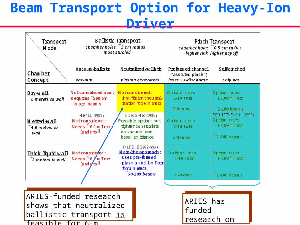
Beam Transport Option for Heavy-Ion Driver
ARIES-funded research shows that neutralized ballistic transport is feasible for 6-m chambers
ARIES has funded research on pinch transport

Neutralized Ballistic TransportPlasma Plug
(externally injected plasma) Low pressure
chamber (~ 10-3 Torr).
Final focus magnet
Target
Volume plasma(from photoionization
of hot target)
Converging ion beam
Chamber Wall
Slide from D. Welch (MRC) presentation at Jan. 2002 ARIES Meeting

Plasma neutralization crucial to good spot
No Plasma Plasma
Pb+2
Pb+3
Pb+4
Pb+5
Pb+2
Pb+3
Pb+4
Pb+5
Log nPb
mean charge state
Stripped ions deflected by un-neutralized charge at beam edge*
Plasma provides > 99% neutralization, focus at 265 cm
*D. A. Callahan, Fusion Eng. Design 32-33, 441 (1996)
Slide from D. Welch (MRC) presentation at Jan. 2002 ARIES Meeting

Conclusions • Photo ionization plasma assists main pulse transport - but
not available for foot pulse
• Without local plasma at chamber, beam transport efficiency is < 50% within 2 mm for “foot” pulse
• Electron neutralization from plasma improves efficiency to 85% - plasma plug greatly improves foot pulse transport
• Lower chamber pressure should help beam transport for both foot and main pulses given plasma at chamber wall
• 6-m NBT transport with good vacuum looks feasible for dry wall chamber design
• System code: “Alpha” factor for neutralization roughly 1 in vacuum, increases with increasing pressure and propagation distance
Slide from D. Welch (MRC) presentation at Jan. 2002 ARIES Meeting

Effect on Non-Condensable Gas and of Vaporized Layer Characteristics on Recondensation
• The presence of non-condensable gas can slow down condensation but effect important at Pg higher than anticipated for IFE
Characteristic time vs. Xe background pressure
1.E-07
1.E-06
1.E-05
1.E-04
1.E-03
1.E-02
1.E-01
1.E+00
1.E+01
1.E+02
1.E+03
1.E+04
1 10 100 1000 10000 100000
Xe partial pressure (Pa)
Ch
ara
cte
risti
c t
ime (
s)
(2 Pa Pb) (10 Pa Pb) (100 Pa Pb)
Approximate range
of interest

Effect on Non-Condensable Gas and of Vaporized Layer Characteristics on
Recondensation• The presence of non-condensable gas
can slow down condensation but effect important at Pg higher than anticipated for IFE
• Based on condensation, it seems better to have a shorter penetration depth (softer spectrum) resulting in less vapor at a higher temperature
Characteristic time vs. Xe background pressure
1.E-07
1.E-06
1.E-05
1.E-04
1.E-03
1.E-02
1.E-01
1.E+00
1.E+01
1.E+02
1.E+03
1.E+04
1 10 100 1000 10000 100000
Xe partial pressure (Pa)
Ch
ara
cte
risti
c t
ime (
s)
(2 Pa Pb) (10 Pa Pb) (100 Pa Pb)
0.0
0.5
1.0
1.5
2.0
2.5
3.0
3.5
4.0
4.5
5.0
0.000
0.005
0.010
0.015
0.020
0.025
0.030
0.035
1.0x10⁻⁶ 2.0x10⁻⁶ 3.0x10⁻⁶ 4.0x10⁻⁶ 5.0x10⁻⁶
Fraction of ion energy used to vaporize Pb armor
Thickness of Vaporized Pb Layer (m)
0.35 0.7 1.0
Photon energy = 115 MJDebris ion energy = 18.1 MJChamber radius = 5 mPb film temperature = 1000 K
Approximate range
of interest