design, testing and strengthening of soft storey of … testing and strengthening of soft storey of...
TRANSCRIPT

Design, Testing and Strengthening of
Soft Storey of Multi-storey Low Cost Housing in Indonesia with Precast Concrete Frame System Nurjaman, H.N. Persada Indonesia University, Indonesia B. H.Hariandja Bandung Institute of Technology, Indonesia L. Faizal Research Institute of Human Setllement, Department of Public Works, Indonesia_ C.R Marbun Directorate of Settlement Development, Department of Public Works, Indonesia H.R Sidjabat, R. Rivky, S. Simanjuntak, Prijasambada, Y.Situmorang, A.K. Manik, D.P. Putra Indonesian Association of Precast Prestressed Engineer, Indonesia SUMMARY: Since 1995, Indonesia had launched massive construction of multi-storey low cost housings for low income people. Precast concrete frame is selected as construction system because it provides quick mass production with economical cost. Typical multi-storey low cost housing in Indonesia are 4 – 6 storey frame buildings, with the first storey being construed as open space for communal facilities, and other storeys being provided with brick walls. From 2006 Yogyakarta and 2007 West Sumatera earthquake inspections, many buildings experienced severe damages due to soft storey effect. This effect was emerged as a consequence of discarding additional stiffness supposedly contributed by brick wall to structural precast concrete frame overall stiffness in structural design. For strengtening of existing low cost housing, and to obtain new more reliable design, some laboratory tests were conducted to estimate additional stiffness contributed by brick wall to structural overall stiffness. This new design has proven in be reliable the two major earthhquake in West Java and West Sumatera at 2009. Keywords: Low cost housing, precast concrete,masonry wall, structural stiffness, soft story effect 1. INTRODUCTION Since 1995, Indonesia had launched massive construction of multi-storey low cost housings for low income people [4]. Indonesia is mainly located at high earthquake risk, so that the building design and construction must be carried out by considering this aspect. Since Aceh earthquake (M=8.9, December 26th,2004), there were series of major earthquakes happening in Indonesia, such as Yogyakarta earthquake (M-6.2, May 27th, 2006) and West Sumatera earthquake (M=6.2, March 6th,2007). In the two events, many buildings experienced severe damages due to soft storey effect. This effect was emerged as a consequence of discarding additional stiffness supposedly contributed by masonry wall to structural precast concrete frame overall stiffness in structural design. For strengtening and improving performance of existing low cost housing, and to obtain improved new design for future application, some laboratory tests were conducted to estimate additional stiffness contributed by brick wall to structural overall stiffness. 2. TYPICAL DESIGN AND CONSTRUCTION OF LOW COST HOUSING IN INDONESIA Typical multi-storey low cost housing in Indonesia are 4 – 6 storey frame buildings, with the first storey being construed as open space for communal facilities, and other storeys being covered with masonry walls. Therefore, soft storey effect is usually encountered at the first storey. One example of
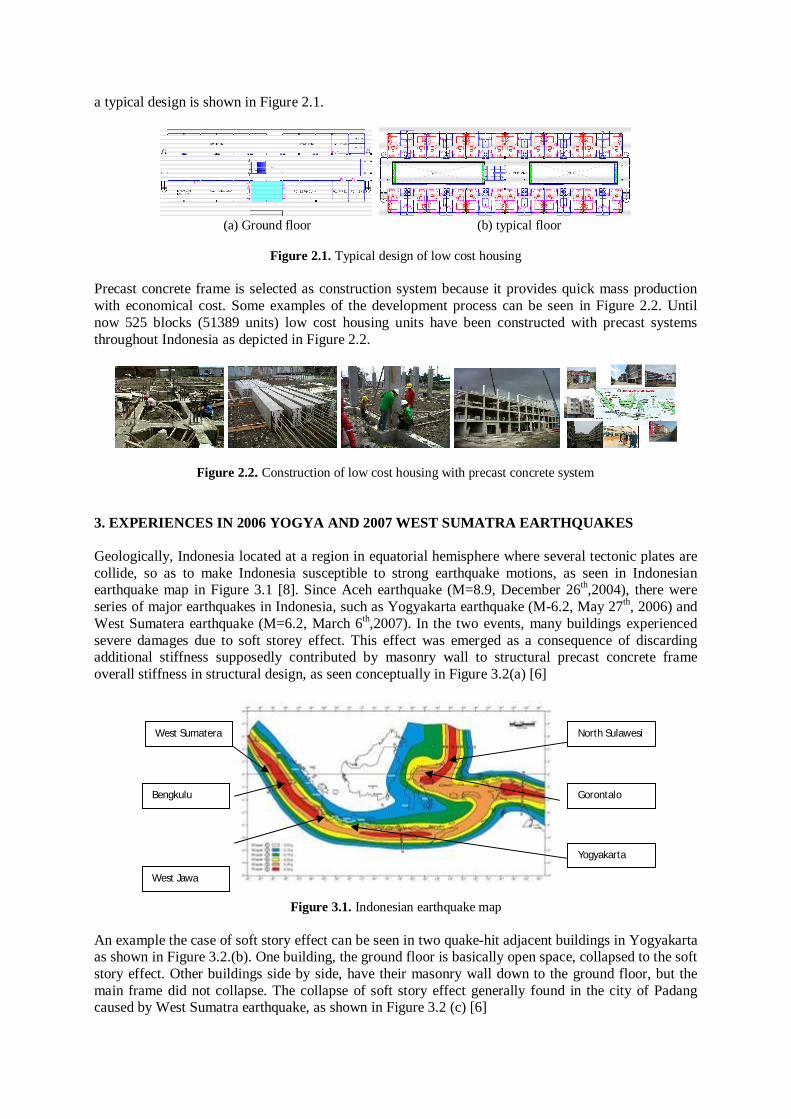
a typical design is shown in Figure 2.1.
(a) Ground floor (b) typical floor
Figure 2.1. Typical design of low cost housing Precast concrete frame is selected as construction system because it provides quick mass production with economical cost. Some examples of the development process can be seen in Figure 2.2. Until now 525 blocks (51389 units) low cost housing units have been constructed with precast systems throughout Indonesia as depicted in Figure 2.2.
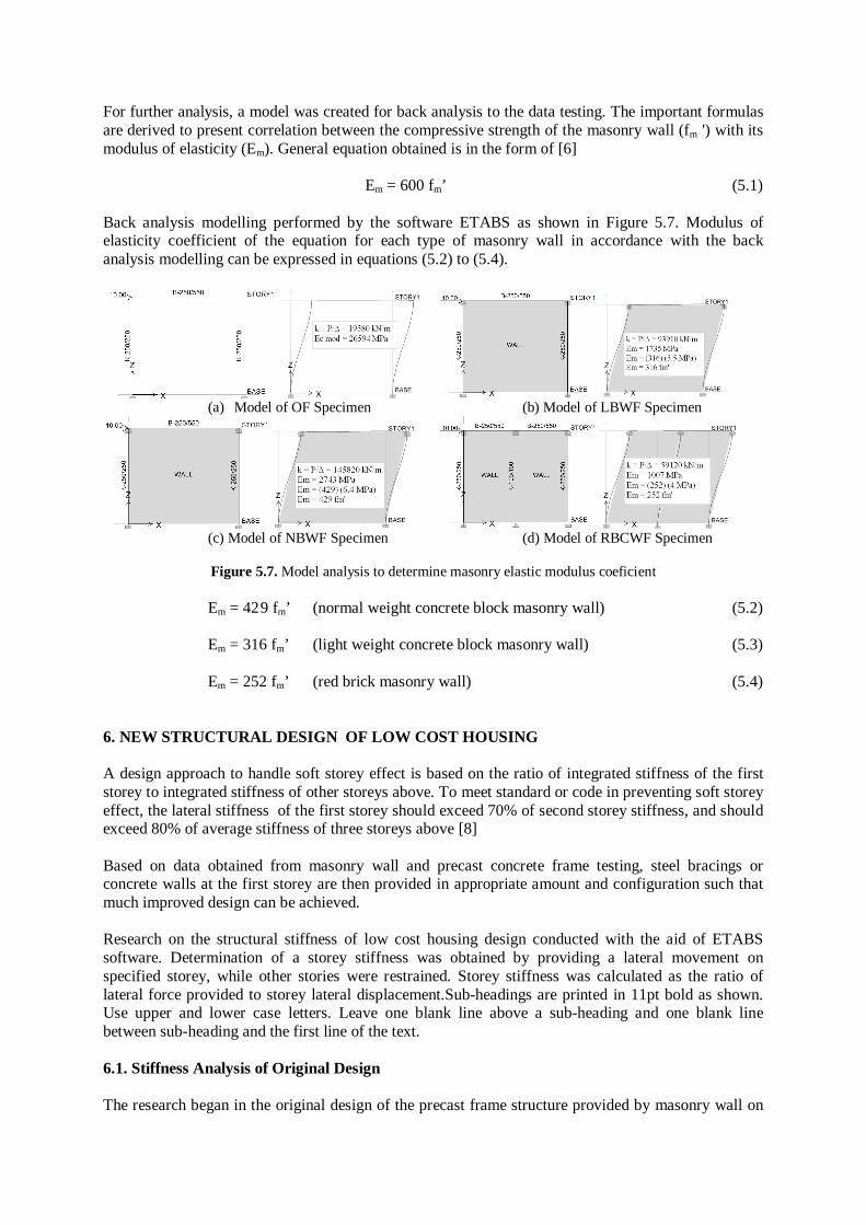
Figure 2.2. Construction of low cost housing with precast concrete system 3. EXPERIENCES IN 2006 YOGYA AND 2007 WEST SUMATRA EARTHQUAKES Geologically, Indonesia located at a region in equatorial hemisphere where several tectonic plates are collide, so as to make Indonesia susceptible to strong earthquake motions, as seen in Indonesian earthquake map in Figure 3.1 [8]. Since Aceh earthquake (M=8.9, December 26th,2004), there were series of major earthquakes in Indonesia, such as Yogyakarta earthquake (M-6.2, May 27th, 2006) and West Sumatera earthquake (M=6.2, March 6th,2007). In the two events, many buildings experienced severe damages due to soft storey effect. This effect was emerged as a consequence of discarding additional stiffness supposedly contributed by masonry wall to structural precast concrete frame overall stiffness in structural design, as seen conceptually in Figure 3.2(a) [6]
Figure 3.1. Indonesian earthquake map
An example the case of soft story effect can be seen in two quake-hit adjacent buildings in Yogyakarta as shown in Figure 3.2.(b). One building, the ground floor is basically open space, collapsed to the soft story effect. Other buildings side by side, have their masonry wall down to the ground floor, but the main frame did not collapse. The collapse of soft story effect generally found in the city of Padang caused by West Sumatra earthquake, as shown in Figure 3.2 (c) [6]
West Jawa
North Sulawesi
Gorontalo
West Sumatera
Bengkulu
Yogyakarta

(a) Conceptual (b) Building failure in Yogyakarta (c) Building failure in Padang
Figure 3.2. Soft story effect In the low cost housing structures with a structural design with still has the soft story effect, total collapse did not occur. The effects of soft story clearly visible in structural damage on the upper column on the ground floor and severe architectural damage downstairs. Figure 3.3 shows the typical damage on one low cost housing caused by the Yogyakarta earthquake, and Figure 3.4 on one of the low cost housing in the city of Padang caused by West Sumatra earthquake.
Figure 3.3. Typical damage of soft story effect caused by Yogyakarta earthquake
Figure 3.4. Typical damage of soft story effect caused by West Sumatera earthquake 4. EARTHQUAKE TESTING OF PRECAST STRUCTURAL CONCRETE SYSTEM The applications of precast concrete systems have attained accelerated progress worldwide, due to their several advantages compared to conventional (cast-in-situ concrete) systems, such as better quality control, speedy construction, economy, and sound environment pertaining in the precast concrete practices. Since 1995, Indonesian technicians and inventors have invented, tested and applied several open frame as well as bearing wall types of medium-rise precast concrete systems. Nowadayas there are about 39 concrete precast systems applicable to constructions of medium up to high rise apartment buildings [5]. See Figure 4.1 as explanation.
Figure 4.1. Examples of Indonesian precast concrete systems Conceptually, open frame systems have to be designed in such a way that, a sway mechanism should be performed by an open frame structural system [6] subject to lateral loads. In this type of failure

mechanism, plastic hinges form at beams and ductile failure behavior of structure is performed so as to save human lives. This case of failure mechanism is incorporated in design codes. A new precast concrete system has to pass several testings to secure its adequate strength, prefereable failure mechanism, and its forecast performance subjected to earthquake motion. At present, testing standard commonly applied in Indonesia is ACI 374.1-05 Acceptance Criteria for Moment Frames Based on Structural Testing [1,3]. Laboratory testings consist at least testing of interior and exterior joints of the new proposed precast system. The specimen is subjected to cyclic loading based on strain control loading up to 3.5% relative drift. Several requirements have to be met by the model, i.e., adequate strength, failure mechanism (plastic hinges on beam, no shear failure) and stronger column compared to beams, and good hysteretic loop of loading (fat, no pinching). The testings were conducted Structural Research Laboratory, Center for Human Settlement, Ministry of Public Works at Bandung, West Java, Indonesia [7]. Testing equipment consists of a frame and a reaction wall as shown in Figure 4.2. Specimen is located and positioned at the frame which transfers vertical load from vertical jack onto the column of the specimen. The imitating earthquake lateral load is induced by a horizontal jack Setting up on reaction wall. With the vertical load held constant throughout the test, the horizontal load is applied as cyclic loading according to ACI 374.1-05.
Figure 4.2. Laboratory testing equipments
An example of laboratory testing results of an interior joint of special moment resisting frame structure (SRMF) of a particular precast concrete systems is depicted in Figure 4.3. Figure 4.3a demonstrates the evolution of joint condition from the beginning test up to the level of 3.5% lateral drift. Figure 4.3b shows hysteretic loop and demonstrates acceptance analysis on strength, rigidity and energy dissipation. Another aspect that may be extracted out from the testing is joint stiffness reduction factor of the precast system when compared to conventional systems. In one example of testing, data entry test at the push over analysis shows the comparison of stiffness of the precast system with theoretical monolithic system has the value of 81% as shown in Figure 4.4 [7].
0.5% 1% 1.5% 2.2% 3.5% 5%
Figure 4.3a. Evolution of exterior joint during testing
P3.5% = 0.9 Pmax > 0.75 OK ! Ang3.5% = 0.09 Ango > 0.05 OK ! E3.5% /Eo = 0.2 > 0.125 OK !
(a) strength (b) stiffness (c) energy dissipation
Figure 4.3b. Acceptance criteria analysis

Figure 4.4. Stiffness comparison between tested precast system with theoritical monolith system
5. TESTING OF STIFFNESS INFLUENCE OF MASONRY WALL Masonry wall materials are widely used in Indonesia namely normal weight concrete block (NBW), light weight concrete block (LBW), and red brick (RBW), as seen in Figure 5.1
(a) Normal weight concrete block (b) Light weight concrete block (c) Red brick
Figure 5.1. Traditionally masonry wall material in Indonesia
The specimen used in these experimental work is already arranged in four various types, i.e., reinforced concrete open Frame (OF, see figure 5.2a), frame with the normal weight concrete block masonry (NBWF, see figure 5.2b), frame with the light of weight concrete block masonry (LBWF, see figure 5.2c) and frame with red brick masonry and practical Column (RBCWF,see figure 5.2d) [2]
(a) OF Specimen (b) LBWF Specimen (c) LBWF Specimen d) RBCWF Specimen
Figure 5.2. Testing speciments The structural testing of frame with or without masonry wall have been done by using a unit full scale testing equipment for static axial-lateral loading test apparatus and loading schedule as it illustrated in figure 5.3. The execution of testing is intended to obtain relationship between the deformation and the lateral load. An axial load with constant magnitude, 130 tf act on the transfer beam before the lateral load works.
Figure 5.3. Set up of speciment testing equipment
The material properties of specimen necessary to describe the actual condition of the performance of the specimen during the load application were obtained by performing testing of materials, the results are shown in Table 5.1
21
55
25
5021
17
50 5025
50
25
602550
12

Table 5.1. Summary of the existing quality of material properties Kind of Properties Value Remark
Concrete : - Compressive strength 21.7 MPa Main bar : - Tensile Strength 390 MPa Deform Bar 4 D 13 Stirrup : - Tensile Strength 240 MPa Plain Bar � 8 -150 Red Brick : - Compressive Strength 4.0 MPa Normal Concrete Block : - Compressive Strength 6.4 MPa Light Concrete Block : - Compressive Strength 5.5 MPa
5.1. Crack Pattern Some various crack pattern occurring on each specimen due the load test that it obtained from the observation as seen in figure 5.4. In general, a diagonal compression strut is formed in NBWF and LBWF speciment. On the RBCWF specimens, the crack pattern leads to integrated wall-frame structural type.
(a) NBWF (b) LBWF (c) RBCWF
Figure 5.4. Crack Pattern
5.2. Load Displacement Curve Load – Tip displacement relationship for each specimen demonstrates distinct and different diagram as shown in figure 5.5a untill figure 5.5d. From those figures, it may be seen that the lateral load acting on the open frame less than that in the frame with masonry wall. It was caused by the increasing of the stiffness of frame and additional of strut action at wall, but then the displacement become smaller. Except of the RBCWF specimen, the behavior were different compared between the NBWF and LBWF, but it was the same with the OF specimen, which is the case where strut of wall did not have influence due of the low quality of red brick and mortar. The envelope curve of four specimens also shown on figure 5.5(e) to provide more clearly differences on the performance. The determination of initial stiffness of each specimen can be seen in figure 5.6. Its shows that very significant increasing of structural stiffness occured due to masonry wall. NBWF is the inheritor of largest increase compare to the other types (7.44 times to OF). (a)OF Specimen (b) LBWF Specimen (c) NBWF Specimen (d) RBCWF Specimen (e) envelope
Figure 5.5. Load-tip displacement
(a) OF k =1.95 tf/mm (b) LBWF k=9,39 tf/mm (c) NBWF k=14.58 tf/mm (d) RBCWF k=5,91 tf/mm Ratio to OF =4.79 Ratio to OF =7.44 Ratio to OF =3.01
Figure 5.6. Determination of initial stiffness
-35-30-25-20-15-10-505
101520253035
-65 -52 -39 -26 -13 0 13 26 39 52 65
DISPLACEME NT (mm)
LA
TE
RA
L L
OA
D (t
onf)
-35-30-25-20-15-10
-505
101520253035
-65 -52 -39 -26 -13 0 13 26 39 52 65
DISPLACEMENT (mm)
LATE
RAL
LO
AD (t
onf)
-35-30-25-20-15-10
-505
101520253035
-65 -52 -39 -26 -13 0 13 26 39 52 65
DISPLACEMEN T (mm)
LA
TE
RA
L L
OA
D (t
onf)
-40
-30
-20
-10
0
10
20
30
40
-65 -52 -39 -26 -13 0 13 26 39 52 65
DISPLACEMENT (mm)
LATE
RAL
LO
AD (t
f)
- 40
- 20
0
2 0
4 0
-6 5 -5 2 -3 9 -2 6 -1 3 0 1 3 2 6 3 9 5 2 6 5
D is p la c e m e n t ( m m )
Late
ral L
oad
(tf)
O F L B W F N B W F R B C W F
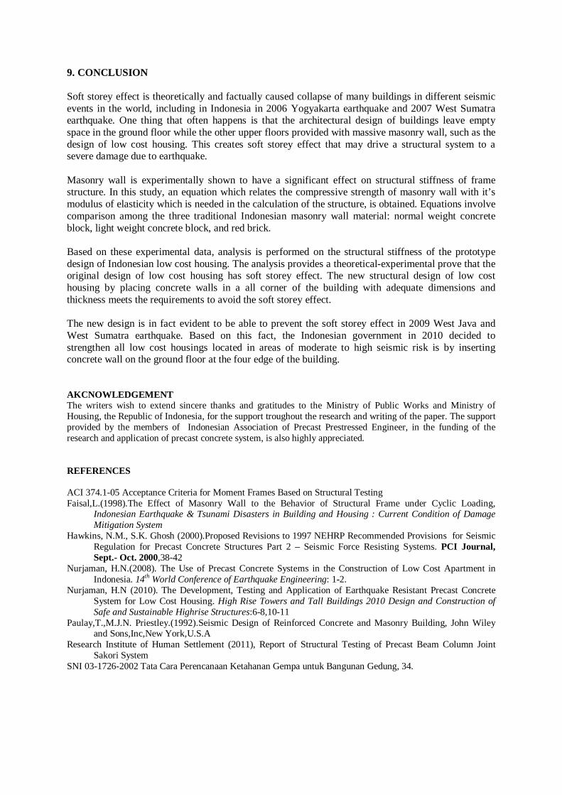
For further analysis, a model was created for back analysis to the data testing. The important formulas are derived to present correlation between the compressive strength of the masonry wall (fm ') with its modulus of elasticity (Em). General equation obtained is in the form of [6]
Em = 600 fm’ (5.1) Back analysis modelling performed by the software ETABS as shown in Figure 5.7. Modulus of elasticity coefficient of the equation for each type of masonry wall in accordance with the back analysis modelling can be expressed in equations (5.2) to (5.4).
(a) Model of OF Specimen (b) Model of LBWF Specimen
(c) Model of NBWF Specimen (d) Model of RBCWF Specimen
Figure 5.7. Model analysis to determine masonry elastic modulus coeficient
Em = 42 9 fm’ (normal weight concrete block masonry wall) (5.2) Em = 316 fm’ (light weight concrete block masonry wall) (5.3) Em = 252 fm’ (red brick masonry wall) (5.4) 6. NEW STRUCTURAL DESIGN OF LOW COST HOUSING A design approach to handle soft storey effect is based on the ratio of integrated stiffness of the first storey to integrated stiffness of other storeys above. To meet standard or code in preventing soft storey effect, the lateral stiffness of the first storey should exceed 70% of second storey stiffness, and should exceed 80% of average stiffness of three storeys above [8] Based on data obtained from masonry wall and precast concrete frame testing, steel bracings or concrete walls at the first storey are then provided in appropriate amount and configuration such that much improved design can be achieved. Research on the structural stiffness of low cost housing design conducted with the aid of ETABS software. Determination of a storey stiffness was obtained by providing a lateral movement on specified storey, while other stories were restrained. Storey stiffness was calculated as the ratio of lateral force provided to storey lateral displacement.Sub-headings are printed in 11pt bold as shown. Use upper and lower case letters. Leave one blank line above a sub-heading and one blank line between sub-heading and the first line of the text. 6.1. Stiffness Analysis of Original Design The research began in the original design of the precast frame structure provided by masonry wall on

the 2nd floor – 5th floor. On each case, storey stiffness is calculated in each floor, which is followed by checking the design requirement, as shown in Figure 6.1 for frame with NBFW and Table 6.1 to Table 6.3. The stiffness reduction of is done by reducing the value of the modulus of elasticity of the column. In all cases, it is proved that the design requirement is not fulfilled if the effect of masonry wall stiffness is taken into account. The first floor rigidity range 47% - 54% floor on it.
Table 6.1. Summary of stiffness analysis original design precast + NBWF
Table 6.2. Summary of stiffness analysis original design precast + LBWF
Table 6.3. Summary of stiffness analysis original design precast + RBCWF
6.2. Stiffness Analysis of New Design To be able to meet the requirements pertaining to a soft storey effect, the design of new structures includes installed concrete walls on all four corners of the building, as shown in Figure 6.2. The analysis shows a concrete wall with a thickness of 200 mm is able to overcome soft storey effects, as demonstrated in Table 6.4 to Table 6.6. As an example, the first floor stiffness in the frame with normal concrete block masonry wall (NBWF), which is the most significant influence one, are ranged between 83% - 88% of the floors above.
Figure 6.2. New structural design – concrete wall at four edge at ground floor
Table 6.4. Summary of stiffness analysis new design precast + NBWF

Table 6.5. Summary of stiffness analysis new design precast + LBWF
Table 6.6. Summary of stiffness analysis new design precast + RBCWF
7. PROVEN EXPERIENCES IN WEST JAVA AND WEST SUMATERA QUAKE 2009 The new design with concrete wall reinforcement at first storey was widely applied since 2008. On September 2nd ,2009 there occured an M=7.2 earthquake in West Java province and not far after, on September 30th, 2009, there was an M = 7.8 earthquake in Padang, West Sumatera province. In the two event there observed very clear evident that low cost housings designed with concrete wall in the first floor did not experience any significant damage, compared to the ones experienced in the previous earthquakes, as seen in figure 7.1 and figure 7.2.
(a) New design - no significant damage (b) Original design - significant damage in first floor
Figure 7.1. Comparison performance of new design and original design in West Java earthquake VI MMI
(a )New design – no significant damage (b) Original design – significant damage in first floor Figure 7.2. Comparison performance of new design and original design in West Sumatera earthquake VIII MMI 8. STRENGTENING OF EXISTING STRUCTURES To strengthen existing structures, steel bracing reinforcement was first applied in Yogyakarta low cost housing (2007), as seen in figure 8.1a. Based on this facts, in 2010 Indonesian government instructed strengthening action of all existing buildings by inserting concrete wall at first storeys, especially buildings located in moderate to high risk region of earthquake, as seen ini figure 8.1b.
Figure 8.1. Steel bracing and concrete wall strengthtening of low cost housing at moderate to high risk zone
9. CONCLUSION Soft storey effect is theoretically and factually caused collapse of many buildings in different seismic events in the world, including in Indonesia in 2006 Yogyakarta earthquake and 2007 West Sumatra earthquake. One thing that often happens is that the architectural design of buildings leave empty space in the ground floor while the other upper floors provided with massive masonry wall, such as the design of low cost housing. This creates soft storey effect that may drive a structural system to a severe damage due to earthquake. Masonry wall is experimentally shown to have a significant effect on structural stiffness of frame structure. In this study, an equation which relates the compressive strength of masonry wall with it’s modulus of elasticity which is needed in the calculation of the structure, is obtained. Equations involve comparison among the three traditional Indonesian masonry wall material: normal weight concrete block, light weight concrete block, and red brick. Based on these experimental data, analysis is performed on the structural stiffness of the prototype design of Indonesian low cost housing. The analysis provides a theoretical-experimental prove that the original design of low cost housing has soft storey effect. The new structural design of low cost housing by placing concrete walls in a all corner of the building with adequate dimensions and thickness meets the requirements to avoid the soft storey effect. The new design is in fact evident to be able to prevent the soft storey effect in 2009 West Java and West Sumatra earthquake. Based on this fact, the Indonesian government in 2010 decided to strengthen all low cost housings located in areas of moderate to high seismic risk is by inserting concrete wall on the ground floor at the four edge of the building. AKCNOWLEDGEMENT The writers wish to extend sincere thanks and gratitudes to the Ministry of Public Works and Ministry of Housing, the Republic of Indonesia, for the support troughout the research and writing of the paper. The support provided by the members of Indonesian Association of Precast Prestressed Engineer, in the funding of the research and application of precast concrete system, is also highly appreciated. REFERENCES ACI 374.1-05 Acceptance Criteria for Moment Frames Based on Structural Testing Faisal,L.(1998).The Effect of Masonry Wall to the Behavior of Structural Frame under Cyclic Loading,
Indonesian Earthquake & Tsunami Disasters in Building and Housing : Current Condition of Damage Mitigation System
Hawkins, N.M., S.K. Ghosh (2000).Proposed Revisions to 1997 NEHRP Recommended Provisions for Seismic Regulation for Precast Concrete Structures Part 2 – Seismic Force Resisting Systems. PCI Journal, Sept.- Oct. 2000,38-42
Nurjaman, H.N.(2008). The Use of Precast Concrete Systems in the Construction of Low Cost Apartment in Indonesia. 14th World Conference of Earthquake Engineering: 1-2.
Nurjaman, H.N (2010). The Development, Testing and Application of Earthquake Resistant Precast Concrete System for Low Cost Housing. High Rise Towers and Tall Buildings 2010 Design and Construction of Safe and Sustainable Highrise Structures:6-8,10-11
Paulay,T.,M.J.N. Priestley.(1992).Seismic Design of Reinforced Concrete and Masonry Building, John Wiley and Sons,Inc,New York,U.S.A
Research Institute of Human Settlement (2011), Report of Structural Testing of Precast Beam Column Joint Sakori System
SNI 03-1726-2002 Tata Cara Perencanaan Ketahanan Gempa untuk Bangunan Gedung, 34.