design · tangram electronic engineering co. ltd 339 north wing, yingwu conference centre no. 6,...
TRANSCRIPT

Waveguide Catalog 15
Design Systems - Components Innovative Solutions
Engineering Over 35 years of
RF Solution engineering
Manufacturing Quality Driven
Customer Focused

Mega Industries, LLC • 28 Sanford Drive, Gorham, Me. 04038 USA
Phone: 207-854-1700 Fax: 207-854-2287 E-Mail: [email protected] www.megaind.com
About Us
MegaSeal® Waveguide Sealing Spacer Allows for pressuriza on with flat‐to‐flat flange connec ons
Available in WR187 to WR2300 (half height available on some popular sizes)

Mega Industries, LLC • 28 Sanford Drive, Gorham, Me. 04038 USA
Phone: 207-854-1700 Fax: 207-854-2287 E-Mail: [email protected] www.megaind.com
Contact Us
Mega Industries, LLC is represented by:
For Italy:
KD Wave s.r.l Viale di Villa Pamphili, 212 00152 Roma - Italy Contact: Pierangelo Vernizzi Phone: +39 06 5344163 Fax: +39 06 91594276 Mobile: +39 3343041253 [email protected]
For South Korea:
SM Engineering #505 Innoplex 13 Yangpyung-dong 3ga, Yeongdeungpo-gu Seoul, 150-103, Korea Phone: 82-2-738-2184 Fax: 82-2-739-9698 [email protected]
For India:
Bryka Electrosystems & Software Pvt Ltd 201 Marine Chambers New Marine Lines V. Thackersey Marg Mumbai—400 020 India Phone: +91 22-2207 4891 ext. 114 Fax: +91 22-2200 2225 Mobile: +91 91-6724 7669 [email protected]
For Israel:
MTI Summit Electronics Ltd. 11 Hamelacha St. Afek Industrial Park Rosh Haayin 4809121, Israel Phone: +972-3-9008900 Fax: +972-3-9008902 [email protected]
For Taiwan R.O.C.
Inno-Tech Solution Corp. 6F.-4, No. 311 Sec. 4 Zhongxiao E. Rd., Taipei City 106, Taiwan Phone: (02)27512158 Fax: (02) 277755282 [email protected]
For France:
Tech-Inter SAS ZA Le Clos de Villarceaux 78770 Thoiry France Tel : +33 (0) 134 942 040 Fax : +33 (0) 134 877 649 Website: www.tech-inter.eu [email protected]
For all other areas:
Mega Industries, LLC 28 Sanford Drive, Gorham, Me. 04038 USA Phone: 207-854-1700 Fax: 207-854-2287 [email protected] www.megaind.com
For Turkey:
MicroTech Corp. Ostim Mh. Melih Gokcek Bulvari Eminel Is Merkezi No: 18/123 Ankara/Turkey Phone: +90 505 815 45 05 Phone: +1 240-482-8558 (US office) E-Mail: [email protected]
For Peoples Republic of China:
Tangram Electronic Engineering Co. LTD 339 North Wing, Yingwu Conference Centre No. 6, Hua Yuan Road, Hai Dian District Beijing 100088 P R China Phone: +86(10)62061100 Fax: +86(10)62061101 [email protected]
For Germany:
Globes Elektronik GmbH & Co KG Berliner Platz 12, 74072 Heilbronn Postfach 1850, 74008 Heilbronn Phone: +49 7131 7810 -0 Fax: +49 7131 7810 20
Globes Elektronik GmbH & Co KG Gutenbergring 41 22848 Norderstedt Phone: +49 40 514817 –0 Fax: +49 50 514817 20
Globes Elektronik GmbH & Co KG Streiflacher Strasse 7, 82110 Postfach 1533, 82102 Germering Phone: +49 89 894606 -0 Fax: +49 89 894606 20 [email protected]
For Switzerland:
TransTech Hochfrequenz AG Hardstrasse 41 5430 Wettingen Tel. +41 56 427 18 93 Fax: +41 56 426 71 23 [email protected]
For Japan:
Shoshin Corporation Suruga Building, 6F 1-7-1 Nihonbashi-muromachi Chuo-Ku, Tokyo 103-0022, JAPAN Contact: Nobuhiko Tsuda Phone: +81-3-3270-5921 [email protected]
For Spain/Portugal:
SpanTech Microwave Technology S.A. Alozaina, 137 Urb. Pinos. 29130 Alhaurin de la Torre Malaga, Spain Phone: +34-95-241-7024 Fax: +34-95-194-8515 [email protected] www.spantech.es

Mega Industries, LLC • 28 Sanford Drive, Gorham, Me. 04038 USA
Phone: 207-854-1700 Fax: 207-854-2287 E-Mail: [email protected] www.megaind.com
Rigid Waveguide
Semi‐Flexible Waveguide
Coaxial Transmission Line
Microwave Transmission Equipment
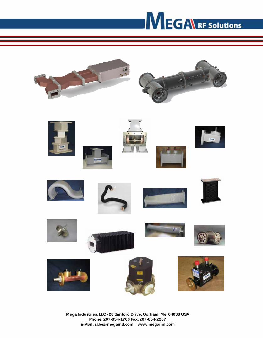
A trusted name in Microwave Technology since 1989, MEGA Industries is now a world leader in the manufacture of Microwave Transmission equipment. We are your one source of high power low frequency, rigid waveguide and waveguide components.
Mega Industries Waveguide is manufactured to precise tolerances calculated to provide op mum VSWR and maximum power handling capabili es. Mega provides waveguide in sizes WR90 through W2300. Full and reduced height configura ons are also available to meet your design requirements. Custom sizes through WR6200 are also available on special request.
Mega’s process of manufacturing Semi‐Flexible Waveguide by brazing the seam off the center assures excellent performance in your high power applica ons. The process of brazing or fusion welding and not joining by epoxy assures a long life joint not prone to spli ng or leaking.
Mega Industries Coaxial Transmission Line is manufactured to exac ng electrical and mechanical tolerances to provide maximum stability and minimum VSWR. Mega manufactures coaxial transmission line and components in sizes Type N to 14‐inch diameter. Using Teflon, Ceramic or other insulator materials and employing special high power connector designs Mega Coaxial Transmission Line can operate at peak performance even in the harshest environments.
Our Products
Mega Industries, LLC • 28 Sanford Drive, Gorham, Me. 04038 USA
Phone: 207-854-1700 Fax: 207-854-2287 E-Mail: [email protected] www.megaind.com

Mega Industries, LLC • 28 Sanford Drive, Gorham, Me. 04038 USA
Phone: 207-854-1700 Fax: 207-854-2287 E-Mail: [email protected] www.megaind.com
Innova ve Custom Solu ons
When ideas push the limits of what has been done before, that is where you will find the experience and engineering talent of the Mega team leading the charge.
Our years of innova on and ability to take concepts from sketch to delivered solu ons are what sets Mega apart. We deliver intricate shapes, uncommon materials, non‐standard waveguide and coax sizes, and solu ons for elevated power levels. Be it water‐cooled coax, ultra high vacuum couplers or Gigawa power levels, Mega is ready to deliver.
Taking the vast array of RF waveguide and coax components available and applying them to create systems is no trivial ma er. It takes years to build a por olio that can then be used as both a star ng point and a catalyst to create new solu ons, adapta ons, and whole new designs that push the envelope and support innova on. Mega has decades of design experience that can be applied to solve even the most difficult design challenge.
WR650 Reduced Height Combiner
This reduced height WR650 Combiner was designed and manufactured for a demanding applica on where precision Phase Matching High Vacuum levels (10¯⁶ Torr) and High Power levels (>Gigawa ) were required. Mega Industries met this challenge and delivered a device that met all of these requirements and kept the customer on schedule.
WR284 High Precision Phase Shi er
This WR284 High Precision Phase Shi er was developed and manufactured for a cu ng edge applica on where highly accurate and repeatable phase shi was required. Mega Industries developed a solu on and delivered a device that will allow these scien sts to con nue research.
Mega Industries, LLC • 28 Sanford Drive, Gorham, Me. 04038 USA
Phone: 207-854-1700 Fax: 207-854-2287 E-Mail: [email protected] www.megaind.com
Rigid Waveguide
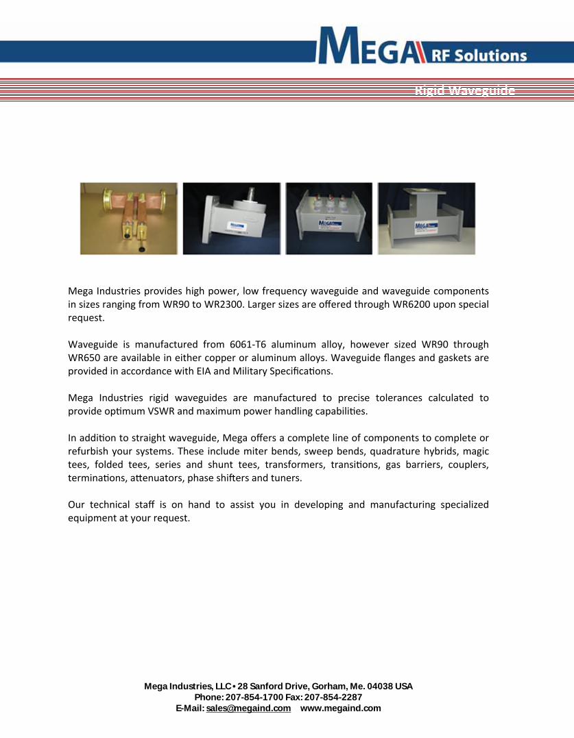
Mega Industries provides high power, low frequency waveguide and waveguide components in sizes ranging from WR90 to WR2300. Larger sizes are offered through WR6200 upon special request. Waveguide is manufactured from 6061‐T6 aluminum alloy, however sized WR90 through WR650 are available in either copper or aluminum alloys. Waveguide flanges and gaskets are provided in accordance with EIA and Military Specifica ons. Mega Industries rigid waveguides are manufactured to precise tolerances calculated to provide op mum VSWR and maximum power handling capabili es. In addi on to straight waveguide, Mega offers a complete line of components to complete or refurbish your systems. These include miter bends, sweep bends, quadrature hybrids, magic tees, folded tees, series and shunt tees, transformers, transi ons, gas barriers, couplers, termina ons, a enuators, phase shi ers and tuners. Our technical staff is on hand to assist you in developing and manufacturing specialized equipment at your request.

Mega Industries, LLC • 28 Sanford Drive, Gorham, Me. 04038 USA
Phone: 207-854-1700 Fax: 207-854-2287 E-Mail: [email protected] www.megaind.com
Rigid Waveguide Straight Sec ons
Mega Industries provides waveguide in sizes WR90 through WR2300. Full and reduced height configura ons are available to meet your requirements. Custom sizes through WR6200 are also available on special request.
Mega Industries’ four‐corner spray arc argon welding process is performed in precision fixtures on WR430 through WR2300 to insure the highest quality waveguide which is mechanically stable and designed for op mum electrical performance. Mega waveguide meets or exceeds EIA and Mil standards for both waveguide(RS‐261A & MIL‐DTL‐85) and flanges (RS271‐A & MIL‐DTL‐3922).
Size WR2300 WR2100 WR1800 WR1500 WR1150 WR975 WR770 WR650 WR430
Raw Tube 3001040X0 3101040X0 3201040X0 3301030X0 3401030X0 3501030X0 3601030X0 3701030X0 3901030X0
Two Flanges 3003040X0 3103040X0 3203040X0 3303030X0 3403030X0 3503030X0 3603030X0 3703030X0 3903030X0
One Flange 3002040X0 3102040X0 3202040X0 3302030X0 3402030X0 3502030X0 3602030X0 3702030X0 3902030X0
Size WR340 WR284 WR229 WR187 WR159 WR137 WR112 WR102 WR90
Raw Tube 4001020X0 4101020X0 4201010X0 4301010X0 4401010X0 4501010X0 4601010X0 4701010X0 4801000X0
Two Flanges 4003020X0 4103020X0 4203010X0 4303010X0 4403010X0 4503010X0 4603010X0 4703010X0 4803000X0
One Flange 4002020X0 4102020X0 4202010X0 4302010X0 4402010X0 4502010X0 4602010X0 4702010X0 4802000X0

Mega Industries, LLC • 28 Sanford Drive, Gorham, Me. 04038 USA
Phone: 207-854-1700 Fax: 207-854-2287 E-Mail: [email protected] www.megaind.com
Rigid Waveguide Sweeps
Mega Industries u lizes the most advanced fabrica ng methods for the forming of precision waveguide sweep bends. Strict adherence to EIA dimensional tolerances insures a minimum reflec on coefficient over the waveguide band. Typical VSWR is 1.05:1
Standard material used is 6061‐T6 Aluminum; however these can also be supplied in Copper and Brass.
The radii listed below are the recommended dimensions for 90° bends; however, other radii and angles can be readily supplied to minimize system design costs. Units are available for both high pressure and high vacuum applica ons.
Pieces are available in full height (2:1 ra o) as well as reduced height configura ons.
Size WR2300 WR2100 WR1800 WR1500 WR1150 WR975 WR770 WR650 WR430
E‐Plane 300404000 310404000 320404000 330403000 340403000 350403000 360403000 370403000 390403000
H‐Plane 300504000 310504000 320504000 330503000 340503000 350503000 360503000 370503000 390503000
Leg x Radius 51.0” x 48.0” 45.0” x 42.0” 39.0” x 36.0” 33.0” x 30.0” 27.0” x 24.0” 21.0” x 18.0” 14.0” x 12.0” 14.0” x 12.0” 10.0” x 8.00”
Leg x Radius 27.0” x 24.0” 27.0” x 24.0” 21.0” x 18.0” 15.0” x 12.0” 15.0” x 12.0” 12.0” x 9.0” 8.0” x 6.0” 8.0” x 6.0” 8.0” x 6.0”
Size WR340 WR284 WR229 WR187 WR159 WR137 WR112 WR102 WR90
E‐Plane 400402000 410402000 420401000 430401000 440401000 450401000 460401000 470401000 480400000
H‐Plane 400502000 410502000 420501000 430501000 440501000 450501000 460501000 470501000 480500000
Leg x Radius 5.0” x 4.0” 4.75” x 3.00” 4.00” x 3.00”
Leg x Radius 7.00” x 6.00” 5.50” x 4.00” 4.50” x 3.50”

Mega Industries, LLC • 28 Sanford Drive, Gorham, Me. 04038 USA
Phone: 207-854-1700 Fax: 207-854-2287 E-Mail: [email protected] www.megaind.com
Rigid Waveguide Miters
Mega Industries high quality 90° waveguide miter bends are of minimum physical size and provide superior electrical performance over a restricted bandwidth (typically VSWR 1.03:1 over a 5% bandwidth).
Standard material used is 6061‐T6 Aluminum; however these can also be supplied in Copper and Brass.
Angles other than 90°, alignment pins, grooved flanges and various aspect ra os can readily be fabricated to meet your feed system requirements. Units are also available for both high pressure and high vacuum applica ons.
Size WR2300 WR2100 WR1800 WR1500 WR1150 WR975 WR770 WR650 WR430
E‐Plane 300604000 310604000 320604000 330603000 340603000 350603000 360603000 370603000 390603000
H‐Plane 303704000 310704000 320704000 330703000 340703000 350703000 360703000 370703000 390703000
Size WR340 WR284 WR229 WR187 WR159 WR137 WR112 WR102 WR90
E‐Plane 400602000 410602000 420601000 430601000 440601000 450601000 460601000 470601000 480600000
H‐Plane 400702000 410702000 420701000 430701000 440701000 450701000 460701000 470701000 470700000

Mega Industries, LLC • 28 Sanford Drive, Gorham, Me. 04038 USA
Phone: 207-854-1700 Fax: 207-854-2287 E-Mail: [email protected] www.megaind.com
Rigid Waveguide Direc onal Couplers
Mega Industries single, double and triple loop couplers are u lized for reflectometer measure‐ments and power monitoring in waveguide transmission systems. With mul ‐loop couplers the couplers can be set at different coupling val‐ues for forward and reverse waves to op mize the dynamic range. All electrical calibra on is directly traceable to the Na onal Bureau of Standards.
Size WR340 WR284 WR229 WR187 WR159 WR137 WR112 WR102 WR90
Monitor 401902000 411902000 421901000 431901000 441901000
Reflectometer 401902010 411902010 421901010 431901010 441901010
Triple Coupler 401902020 411902020 421901020 431901020 441901020
Typical Electrical Specifications
Mainline VSWR 1.05:1
Sidearm VSWR 1.25:1
Coupling Factor 40 to 75 dB +/- 1.0 dB (specify at order)
Coupling Variation +/- 1 dB
Directivity 27 dB Nominal
Insertion Loss Less than 0.05 dB
Terminations Included, External, Two Watt on Standard Units
Size WR2300 WR2100 WR1800 WR1500 WR1150 WR975 WR770 WR650 WR430
Monitor 301904000 311904000 321904000 331903000 341903000 351903000 361903000 371903000 391903000
Reflectometer 301904010 311904010 321904010 331903010 341903010 351903010 361903010 371903010 391903010
Triple Coupler 301904020 311904020 321904020 331903020 341903020 351903020 361903020 371903020 391903020

Mega Industries, LLC • 28 Sanford Drive, Gorham, Me. 04038 USA
Phone: 207-854-1700 Fax: 207-854-2287 E-Mail: [email protected] www.megaind.com
A line of Magic tees manufactured to exac ng electrical and mechanical specifica ons are available for every system layout.
Our manufacturing processes provide maximum symmetry in fabrica on and resul ng in the following electrical performance over a 10% bandwidth.
Electrical Performance over a 10% Waveguide Bandwidth
Colinear Balance +/- 0.1 dB
Insertion Loss Less than 0.1 dB
E-H Isolation 30 dB Minimum
VSWR 1.10:1
Size WR2300 WR2100 WR1800 WR1500 WR1150 WR975 WR770 WR650 WR430
Catalog # 301304000 311304000 321304000 331303000 341303000 351303000 361303000 371303000 391303000
Size WR340 WR284 WR229 WR187 WR159 WR137 WR112 WR102 WR90
Catalog # 401302000 411302000 421301000 431301000 441301000 451301000 461301000 471301000 481300000
Rigid Waveguide Magic Tees

Mega Industries, LLC • 28 Sanford Drive, Gorham, Me. 04038 USA
Phone: 207-854-1700 Fax: 207-854-2287 E-Mail: [email protected] www.megaind.com
Rigid Waveguide Folded Magic Tees
For monopulse applica ons or when the use of standard magic tees presents a mechanical interfacing problem, folded tee configura ons are available to our dimensions or custom designed to your specific system requirements. As well as E plane and H‐plane folded tees, units are available in 4:1 aspect ra os, heavy wall waveguide, or with special flange configura ons.
Size WR2300 WR2100 WR1800 WR1500 WR1150 WR975 WR770 WR650 WR430
E‐Plane 301404020 311404020 321404020 331403020 341403020 351403020 361403020 371403020 391403020
H‐Plane 301404000 311404000 321404000 331403000 341403000 351403000 361403000 371403000 391403000
Size WR340 WR284 WR229 WR187 WR159 WR137 WR112 WR102 WR90
E‐Plane 401402010 411402010 424201010 434201010 444201010 454201010 464201010 474201010 484201010
H‐Plane 401402000 411402000 424201000 434201000 444201000 454201000 464201000 474201000 484201000
Mega Industries, LLC • 28 Sanford Drive, Gorham, Me. 04038 USA
Phone: 207-854-1700 Fax: 207-854-2287 E-Mail: [email protected] www.megaind.com
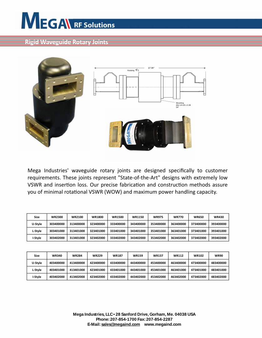
Mega Industries' waveguide rotary joints are designed specifically to customer requirements. These joints represent "State‐of‐the‐Art" designs with extremely low VSWR and inser on loss. Our precise fabrica on and construc on methods assure you of minimal rota onal VSWR (WOW) and maximum power handling capacity.
Rigid Waveguide Rotary Joints
Size WR2300 WR2100 WR1800 WR1500 WR1150 WR975 WR770 WR650 WR430
U‐Style 303400000 313400000 323400000 333400000 343400000 353400000 363400000 373400000 393400000
L‐Style 303401000 313401000 323401000 333401000 343401000 353401000 363401000 373401000 393401000
I‐Style 303402000 313401000 323402000 333402000 343402000 353402000 363402000 373402000 393402000
Size WR340 WR284 WR229 WR187 WR159 WR137 WR112 WR102 WR90
U‐Style 403400000 413400000 423400000 433400000 443400000 453400000 463400000 473400000 483400000
L‐Style 403401000 413401000 423401000 433401000 443401000 453401000 463401000 473401000 483401000
I‐Style 403402000 413402000 423402000 433402000 443402000 453402000 463402000 473402000 483402000
Rotating
Mounting (8x) 1/4-20 x 0.38 DP

Mega Industries, LLC • 28 Sanford Drive, Gorham, Me. 04038 USA
Phone: 207-854-1700 Fax: 207-854-2287 E-Mail: [email protected] www.megaind.com
Quadrature, or 90 degree, equal power division hybrids are available as a basic subsystem building block. Unequal 4.77 dB and 6 dB units are also available. Contact Mega's sales team for other possible splits.
These units are designed to meet very ght electrical specs at specific frequencies and can meet very respectable values over a 10% waveguide bandwidth.
Electrical Performance over a 10% Waveguide Bandwidth
Amplitude Balance +/- 0.25 dB
Phase Balance 90 +/- 2°
Insertion Loss Less than 0.1 dB
Isolation 28 dB Minimum
VSWR 1.10:1
Rigid Waveguide Short Slot Hybrid
Size WR2300 WR2100 WR1800 WR1500 WR1150 WR975 WR770 WR650 WR430
3 dB 301504000 311504000 321504000 331503000 341503000 351503000 361503000 371503000 391503000
4.77 dB 301504020 311504020 321504020 331503020 341503020 351503020 361503020 371503020 391503020
6 dB 301504040 311504040 324504040 331503040 341503040 351503040 361503040 371503040 391503040
Size WR340 WR294 WR229 WR187 WR159 WR137 WR112 WR102 WR90
3 dB 401502000 411502000 421501000 431501000 441501000 451501000 461501000 471501000 481500000
4.77 dB 401502020 411502020 421501020 431501020 441501020 451501020 461501020 471501020 481500020
6 dB 401502040 411502040 421501040 431501040 441501040 451501040 461501040 471501040 481500040
Mega Industries, LLC • 28 Sanford Drive, Gorham, Me. 04038 USA
Phone: 207-854-1700 Fax: 207-854-2287 E-Mail: [email protected] www.megaind.com
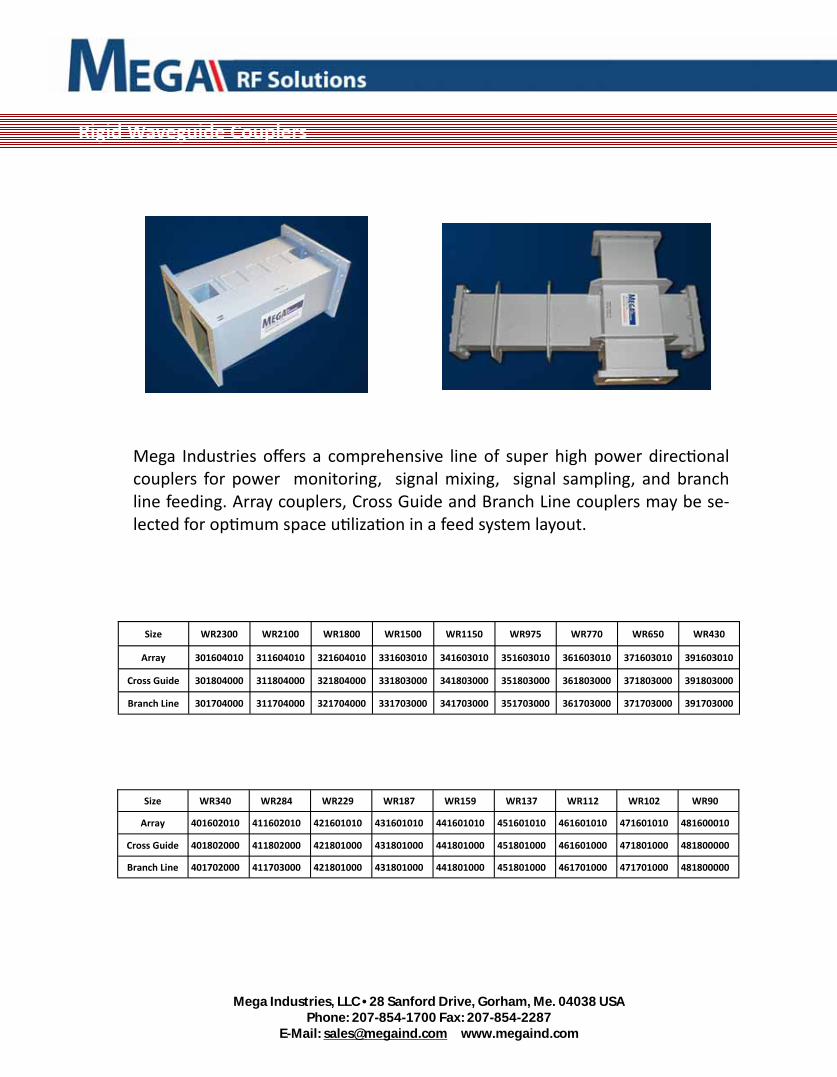
Mega Industries offers a comprehensive line of super high power direc onal couplers for power monitoring, signal mixing, signal sampling, and branch line feeding. Array couplers, Cross Guide and Branch Line couplers may be se‐lected for op mum space u liza on in a feed system layout.
Rigid Waveguide Couplers
Size WR2300 WR2100 WR1800 WR1500 WR1150 WR975 WR770 WR650 WR430
Array 301604010 311604010 321604010 331603010 341603010 351603010 361603010 371603010 391603010
Cross Guide 301804000 311804000 321804000 331803000 341803000 351803000 361803000 371803000 391803000
Branch Line 301704000 311704000 321704000 331703000 341703000 351703000 361703000 371703000 391703000
Size WR340 WR284 WR229 WR187 WR159 WR137 WR112 WR102 WR90
Array 401602010 411602010 421601010 431601010 441601010 451601010 461601010 471601010 481600010
Cross Guide 401802000 411802000 421801000 431801000 441801000 451801000 461601000 471801000 481800000
Branch Line 401702000 411703000 421801000 431801000 441801000 451801000 461701000 471701000 481800000

Mega Industries, LLC • 28 Sanford Drive, Gorham, Me. 04038 USA
Phone: 207-854-1700 Fax: 207-854-2287 E-Mail: [email protected] www.megaind.com
For extremely high power applica ons, waveguide phase shi ers of the short slot hybrid design are u lized. Non‐contac ng, double bucket shor ng assemblies, mounted on Teflon runners, are u lized for long term reliability. With an inser on loss characteris c of less than 0.05 dB., maximum power transfer is assured for both manual and motorized units.
For ultra high power or cri cal phase applica ons Mega can incorporate water cooling the these designs.
Size WR2300 WR2100 WR1800 WR1500 WR1150 WR975 WR770 WR650 WR430
Manual 302204000 312204000 322204000 332203000 342203000 352203000 362203000 372203000 392203000
Motorized 302204010 312204010 322204010 332203010 342203010 352203010 362203010 372203010 392203010
3‐Probe Manual
302204020 312204020 322204020 332203020 342203020 352203020 362203020 372203020 392203020
3‐Probe Motorized
302204030 312204030 322204030 332203030 342203030 352203030 362203030 372203030 392203030
Size WR340 WR284 WR229 WR187 WR159 WR137 WR112 WR102 WR90
Manual 402202000 412202000 422201000 432201000 442201000 452201000 462201000 472201000 482200000
Motorized 402202010 412202010 422201010 432201010 442201010 452201010 462201010 472201010 482200010
3‐Probe Manual
402202020 412202020 422201020 432201020 442201020 452201020 462201020 472201020 482200020
3‐Probe Motorized
402202030 412202030 422201030 432201030 442201030 452201030 462201030 472201030 482200030
Rigid Waveguide Phase Shi ers
Mega Industries, LLC • 28 Sanford Drive, Gorham, Me. 04038 USA
Phone: 207-854-1700 Fax: 207-854-2287 E-Mail: [email protected] www.megaind.com
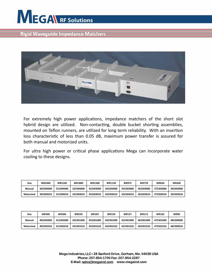
For extremely high power applica ons, impedance matchers of the short slot hybrid design are u lized. Non‐contac ng, double bucket shor ng assemblies, mounted on Teflon runners, are u lized for long term reliability. With an inser on loss characteris c of less than 0.05 dB, maximum power transfer is assured for both manual and motorized units.
For ultra high power or cri cal phase applica ons Mega can incorporate water cooling to these designs.
Rigid Waveguide Impedance Matchers
Size WR2300 WR2100 WR1800 WR1500 WR1150 WR975 WR770 WR650 WR430
Manual 302304000 312304000 322304000 332303000 342303000 352303000 362303000 372303000 392303000
Motorized 302304010 312304010 322304010 332303010 342303010 352303010 362303010 372303010 392303010
Size WR340 WR284 WR229 WR187 WR159 WR137 WR112 WR102 WR90
Manual 402302000 412302000 422301000 432301000 442301000 452301000 462301000 472301000 482300000
Motorized 402302010 412302010 422301010 432301010 442301010 452301010 462301010 472301010 482300010

Mega Industries, LLC • 28 Sanford Drive, Gorham, Me. 04038 USA
Phone: 207-854-1700 Fax: 207-854-2287 E-Mail: [email protected] www.megaind.com
Rigid Waveguide A enuators
Mega Industries offers both fixed and variable precision waveguide a enuators for the most demanding system requirements. Low to medium power devices u lize high density shaped microwave absorbing elements permanently a ached to a standard waveguide sec on. The VSWR of the fixed a enuators is less than 1.10.1 over a 10% band and the variable units exhibit a 1.15:1 maximum VSWR. When requested, calibra on charts traceable to the Na onal Bureau of Standards can be supplied.
For extremely high power or for low loss applica ons, hybrid style variable a enuators are available. These units, which exhibit a minimum inser on loss of 0.05 dB can be readily varied to 30 dB a enua on under full transmi er power. Both manual drive and motor driven devices are available to meet the most exac ng requirements.
For ultra high power or cri cal phase applica ons Mega can incorporate water cooling to these designs.
Size WR2300 WR2100 WR1800 WR1500 WR1150 WR975 WR770 WR430
Fixed High Power
302504020 312504020 322504020 332503020 342503020 352503020 362503020 392503020
Fixed Low Power
302504000 312504000 322504000 332503000 342503000 352503000 362503000 392503000
Variable High Power
302504030 312504030 322504030 332503030 342503030 342503030 362503030 392503030
Variable Low Power
302504010 312504010 322504010 332503010 342503010 342503010 352603010 392503010
WR650
372503020
372503000
372503030
372503010
Size WR340 WR284 WR229 WR187 WR159 WR137 WR112 WR102
Fixed High Power
402502020 412502020 422501020 432501020 442501020 452501020 462501020 472501020
Fixed Low Power
402502000 412502000 422501000 432501000 442501000 452501000 462501000 472501000
Variable High Power
402502030 412502030 422501030 432501030 442501030 452501030 462501030 472501030
Variable Low Power
402502010 412502010 422501010 432501010 442501010 452501010 462501010 472501010
WR90
482500020
482500000
482500030
482500010
Mega Industries, LLC • 28 Sanford Drive, Gorham, Me. 04038 USA
Phone: 207-854-1700 Fax: 207-854-2287 E-Mail: [email protected] www.megaind.com
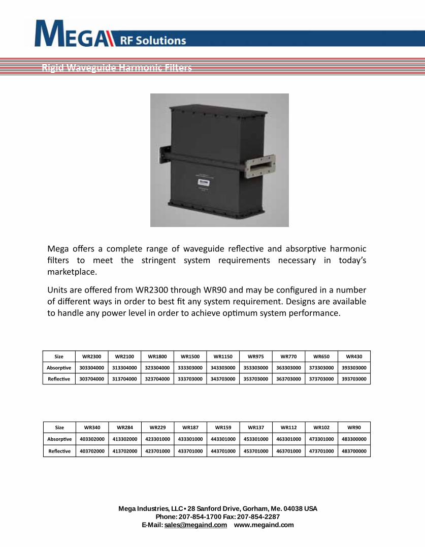
Mega offers a complete range of waveguide reflec ve and absorp ve harmonic filters to meet the stringent system requirements necessary in today’s marketplace.
Units are offered from WR2300 through WR90 and may be configured in a number of different ways in order to best fit any system requirement. Designs are available to handle any power level in order to achieve op mum system performance.
Rigid Waveguide Harmonic Filters
Size WR2300 WR2100 WR1800 WR1500 WR1150 WR975 WR770 WR650 WR430
Absorp ve 303304000 313304000 323304000 333303000 343303000 353303000 363303000 373303000 393303000
Reflec ve 303704000 313704000 323704000 333703000 343703000 353703000 363703000 373703000 393703000
Size WR340 WR284 WR229 WR187 WR159 WR137 WR112 WR102 WR90
Absorp ve 403302000 413302000 423301000 433301000 443301000 453301000 463301000 473301000 483300000
Reflec ve 403702000 413702000 423701000 433701000 443701000 453701000 463701000 473701000 483700000

Mega Industries, LLC • 28 Sanford Drive, Gorham, Me. 04038 USA
Phone: 207-854-1700 Fax: 207-854-2287 E-Mail: [email protected] www.megaind.com
Mega Industries manufactures a wide range of waveguide termina ons ranging from instrument level, low power test termina ons to very high power system loads.
High power loads are offered in a number of configura ons. Air cooled loads are available to handle most “medium power” applica ons while numerous styles of water cooled loads are available for high power applica ons.
Mega engineers are readily available to discuss custom system load requirements.
Mega also provides Short Circuits & Test Termina ons.
Rigid Waveguide High Power Loads
Size WR2300 WR2100 WR1800 WR1500 WR1150 WR975 WR770 WR650 WR430
Air Cooled 303504000 313504000 323504000 333503000 343503000 353503000 363503000 373503000 393503000
Water Cooled
303504010 313504010 323504010 333503010 343503010 353503010 363503010 373503010 393503010
Water Load 303504020 313504020 323504020 333503020 343503020 343503020 363503020 373503020 393503020
Size WR340 WR284 WR229 WR187 WR159 WR137 WR112 WR102 WR90
Air Cooled 403502000 413502000 423501000 433501000 443501000 453501000 463501000 473501000 483500000
Water Cooled
403502010 413502010 423501010 433501010 443501010 453501010 463501010 473501010 483500010
Water Load 403502020 413502020 423501020 433501020 443501020 453501020 463501020 473501020 483500020

Mega Industries, LLC • 28 Sanford Drive, Gorham, Me. 04038 USA
Phone: 207-854-1700 Fax: 207-854-2287 E-Mail: [email protected] www.megaind.com
Rigid Waveguide Switches
Mega Industries offers a comprehensive line of waveguide switch configura ons, both manual and motorized, to meet the requirements of your microwave transmission system.
This line includes:
Waveguide shu ers for personnel protec on in mul ple transmi er applica ons.
Three‐port patch link assemblies for infrequent, preplanned SPDT opera ons.
The conven onal "T" configura on, for extremely high power use or where very high port isola on is required.
E‐plane rotary transfer configura on for stand‐by transmi ers or matrix building elements.
Size WR2300 WR2100 WR1800 WR1500 WR11550 WR975 WR770 WR650 WR430
Shu er Man‐ual
303200000 313200000 323200000 333200000 343200000 353200000 363200000 373200000 393200000
Shu er Motorized
303200010 313200010 323200010 333200010
343200010 353200010 363200010 373200010 393200010
T Style Manual
303200020 313200020 323200020 333200020 343200020 353200020 363.200020 373200020 393200020
T Style Motorized
303200030 313200030 323200030 333200030 343200030 353200030 363200030 373200030 393200030
Y Style Manual
303200040 313200040 323200040 333200040 343200040 353200040 363200040 373200040 393200040
Y Style Motorized
303200050 313200050 323200050 333200050 343200050 353200050 363200050 373200050 393200050
Contact Mega’s sales team or go to www.megaind.com for other available sizes

Mega Industries, LLC • 28 Sanford Drive, Gorham, Me. 04038 USA
Phone: 207-854-1700 Fax: 207-854-2287 E-Mail: [email protected] www.megaind.com
Rigid Waveguide Tees
A complete line of series and shunt tees manufactured to exac ng electrical and mechanical specifica ons are available for every system layout.
Our manufacturing processes provide maximum symmetry in fabrica on and resul ng in the following electrical performance over a 10% bandwidth.
Electrical Performance over a 10% Waveguide Bandwidth
Colinear Balance +/- 0.1 dB
Insertion Loss Less than 0.1 dB
E-H Isolation 30 dB Minimum
VSWR 1.10:1
Size WR2300 WR2100 WR1800 WR1500 WR1150 WR975 WR770 WR650 WR430
Shunt unmatched
301204010 311204010 321204010 331203010 341203010 351203010 361203010 371203010 391203010
Shunt matched
301204020 311204020 321204020 331203020 341203020 351203020 361203020 371203020 391203020
Series unmatched
301204030 311204030 321204030 331203030 341203030 351203030 361203030 371203030 391203030
Series matched
301204040 311204040 321204040 331203040 341203040 351203040 361203040 371203040 391203040
Size WR340 WR284 WR229 WR187 WR159 WR137 WR112 WR102 WR90
Shunt unmatched
401202010 411202010 421201010 431201010 441201010 451201010 461201010 471201010 481200010
Shunt matched
401202020 411202020 421201020 431201020 441201020 451201020 461201020 471201020 481200020
Series unmatched
401202030 411202030 421201030 431201030 441201030 451201030 461201030 471201030 481200030
Series matched
401202040 411202040 421201040 431201040 441201040 451201040 461201040 471201040 481200040

Mega Industries, LLC • 28 Sanford Drive, Gorham, Me. 04038 USA
Phone: 207-854-1700 Fax: 207-854-2287 E-Mail: [email protected] www.megaind.com
Flush waveguide flanges in 6061‐T6 aluminum plate are available for prototype fabrica on or field installa on. These flanges are pre‐machined to EIA dimensions and are of sufficient thickness to allow a minimum of 1/8" for facing a er welding. Special bolt hole pa erns, double flanges, 4:1 aspect ra os, grooves, and alignment pins can be readily supplied to meet special feed system requirements.
Size WR2300 WR2100 WR1800 WR1500 WR1150 WR975 WR770 WR650 WR430
Thru Flange 302604000 312604000 322604000 332603000 342603000 352603000 362603000 372603000 392603000
Socket Flange 302604010 312604010 322604010 332603010 342603010 352603010 362603010 372603010 392603010
Size WR340 WR284 WR229 WR187 WR159 WR137 WR112 WR102 WR90
Thru Flange 402602000 412602000 422601000 432601000 442601000 452601000 462601000 472601000 482600000
Socket Flange 402602010 412602010 422601010 432601010 442601010 452601010 462601010 472601010 482600010
Rigid Waveguide Flanges

Mega Industries, LLC • 28 Sanford Drive, Gorham, Me. 04038 USA
Phone: 207-854-1700 Fax: 207-854-2287 E-Mail: [email protected] www.megaind.com
Mega Industries offers a complete line of waveguide precision Calibra on Kits for use with Vector Network Analyzer systems.
Tradi onal calibra on kits u lize three impedance standards and one transmission standard to fully effect a full two port calibra on. The standards normally used are shorts, opens, loads and a through connec on resul ng in the common “SOLT Calibra on Kit”. Unlike Coaxial kits, where a “calibrated open” is readily achievable, SOLT waveguide
calibra on kits u lize Offset Short‐Circuit sec ons to represent these two parameters. The length of the offsets, which are set as λ/8 and 3λ/8 long, are designed to provide a balanced phase response over the waveguide opera ng frequency range.
In addi on, Mega provides precision Coaxial to Waveguide Transi ons, which typically display a VSWR of be er than 1.15:1 over the complete waveguide band and be er than 1.10:1 over more than 80% of the band. This provides for extreme accuracy when measuring low inser on loss devices.
Also offered by Mega is the Thru Reflect Line (TRL) two port calibra on kit, which u lizes 3 standards to define the calibrated reference plane. Precision waveguide to coaxial transi ons are used in conjunc on with a “flush” Short circuit plate and a precision λ/4 waveguide sec on designed to provide a balanced phase response over the waveguide opera ng frequency range.
Rigid Waveguide Calibra on Kits
Size WR2300 WR2100 WR1800 WR1500 WR1150 WR975 WR770 WR650 WR430
SSL 304504000 314504000 324504000 334503000 344503000 354503000 364503000 374503000 394503000
TRL 304604000 314604000 324604000 334603000 344603000 354603000 364603000 374603000 394603000
Size WR340 WR284 WR229 WR187 WR159 WR137 WR112 WR102 WR90
SSL 404502000 414502000 424501000 434501000 444501000 454501000 464501000 474501000 484500000
TRL 404602000 414602000 424601000 434601000 444601000 454601000 464601000 474601000 484600000

Mega Industries, LLC • 28 Sanford Drive, Gorham, Me. 04038 USA
Phone: 207-854-1700 Fax: 207-854-2287 E-Mail: [email protected] www.megaind.com
Mega Industries manufacturers a complete line of waveguide to coaxial transi ons. For laboratory tes ng or other low power applica ons, we recommend “Probe type” transi ons to Type‐N coaxial connector; while our low VSWR “cross‐bar” design provides op mum electrical performance for high power applica ons.
Standard transi ons have fixed flanges. The 7/8, 1 5/8, 3 1/8, 6 1/8 coaxial adaptors for WR1800 and larger waveguides are female; other rigid coaxial adaptors are male. Also available are water‐cooled transi ons, half‐height, and adaptors for SC, APC‐7, SMA and other configura ons.
Rigid Waveguide Transi ons to Coaxial

Mega Industries, LLC • 28 Sanford Drive, Gorham, Me. 04038 USA
Phone: 207-854-1700 Fax: 207-854-2287 E-Mail: [email protected] www.megaind.com
Size WR2300 WR2100 WR1800 WR1500 WR1150 WR975 WR770 WR650 WR430
Type N 3010040N0 3110040N0 3210040N0 3310030N0 3410030N0 3510030N0 3610030N0 3710030N0 3910030N0
SMA 3010040S0 3110040S0 3210040S0 3310030S0 3410030S0 3510030S0 3610030S0 3710030S0 3910030S0
7/8 351003010 361003010 371003010 391003010
1‐5/8 351003020 361003020 371003020 391003020
3‐1/8 301004030 311004030 321004030 331003030 341003030 351003030 361003030 371003030
4‐1/16 301004040 311004040 321004040 331003040 341003040 351003040 361003040
6‐1/8 301004050 311004050 321004050 331003050 341003050
Size WR340 WR284 WR229 WR187 WR159 WR137 WR112 WR102 WR90
Type N 4010020N0 4110020N0 4210010N0 4310010N0 4410010N0 4510010N0 4610010N0 4710010N0 4810000N0
SMA 4010020S0 4110020S0 4210010S0 4310010S0 4410010S0 4510010S0 4610010S0 4710010S0 4810000S0
7/8 401002010 411002010
1‐5/8 401002020 411002020
3‐1/8
4‐1/16
6‐1/8
For other sizes contact Mega’s Sales department at [email protected] or Mega’s website at www.megaind.com

Mega Industries, LLC • 28 Sanford Drive, Gorham, Me. 04038 USA
Phone: 207-854-1700 Fax: 207-854-2287 E-Mail: [email protected] www.megaind.com
Rigid Waveguide Probe & Stub Tuners
Probe Tuners Mega Industries waveguide probe tuners offer a form of in line waveguide structures, which will match out up to a 1.5:1 VSWR at any phase angle when placed in a waveguide circuit for subsystem op miza on. The devices u lize Mega Industries contac ng plunger designs for high power opera on. Three probe units will readily match out a 1.25:1 mismatch while the 5 probe unit will match a 1.5:1 mismatch over a limited bandwidth. These devices are available for either manual or motorized opera on. Remote Readouts and opera ng panels may be provided upon request. Contact the Mega Engineering Sales team for more informa on
Stub Tuners Mega Industries waveguide stub tuners offer a form of in line waveguide structures to be used for impedance matching. These units, which will match out up to a 4:1 VSWR when appropriately placed in a waveguide circuit, u lize Mega Industries non contac ng, single or double bucket short circuit designs for high power opera on. Low power versions are also available u lizing contac ng short circuit designs. Single stub units will match out a 2:1 mismatch over a 5% band while the double stub unit will match a 4:1 mismatch over a 20% bandwidth These devices are available for either manual or motorized opera on. Remote Readouts and opera ng panels may be provided upon request. Contact the Mega Engineering Sales team for more informa on.
WR650 5‐Probe Tuner WR975 2‐Stub Tuner

Mega Industries, LLC • 28 Sanford Drive, Gorham, Me. 04038 USA
Phone: 207-854-1700 Fax: 207-854-2287 E-Mail: [email protected] www.megaind.com
Size WR2300 WR2100 WR1800 WR1500 WR1150 WR975 WR770 WR650 WR430
3‐Probe Manual
302104000 312104000 322104000 332103000 342103000 352103000 362103000 372103000 392103000
3‐Probe Motorized
302104010 312104010 322104010 332103010 342103010 352103010 362103010 372103010 392103010
5‐Probe Manual
302104020 312104020 322104020 332103020 342103020 352103020 362103020 372103020 392103020
5‐Probe Motorized
302104030 312104030 322104030 332103030 342103030 352103030 362103030 372103030 392103030
Size WR340 WR284 WR229 WR187 WR159 WR137 WR112 WR102 WR90
3‐Probe Manual
402102000 412102000 422101000 432101000 442101000 452101000 462101000 472101000 482100000
3‐Probe Motorized
402102010 412102010 422101010 432101010 442101010 452101010 462101010 472101010 482100010
5‐Probe Manual
402102020 412102020 422101020 432101020 442101020 452101020 462101020 472101020 482100020
5‐Probe Motorized
402102030 412102030 422101030 432101030 442101030 452101030 462101030 472101030 482100030
Size WR2300 WR2100 WR1800 WR1500 WR1150 WR975 WR770 WR650 WR430
Manual 304304000 314304000 324304000 334303000 344303000 354303000 364303000 374303000 394303000
Motorized 304304010 314304010 324304010 334203010 344303010 354303010 364303010 374303010 394303010
Size WR340 WR284 WR229 WR187 WR159 WR137 WR112 WR102 WR90
Manual 404302000 414302000 424301000 434301000 444301000 454301000 464301000 474301000 494300000
Motorized 404302010 434102010 424301010 434301010 444301010 454301010 464301010 474301010 494300010
Probe Tuners
Stub Tuners

Mega Industries, LLC • 28 Sanford Drive, Gorham, Me. 04038 USA
Phone: 207-854-1700 Fax: 207-854-2287 E-Mail: [email protected] www.megaind.com
Rigid Waveguide Gain Horns
Mega Industries Standard Gain Horns have a wide range of applica ons such as transmi ng, receiving or sampling.
The high precision manufacturing of the Mega Gain Horns assure you of accurate, repeatable gain reference. Horns are built and manufactured per the NRL standards, Report #4333.
All Mega Industries Gain Horns are manufactured from high quality 6061‐T6 aluminum and are given a chromate conversion treatment in accordance with MIL‐C‐5541. Units are painted in our standard Mega Grey but can be custom painted to meet your system requirements.
General Specification:
Variation of Mid-band ± 2 dB
Maximum VSWR 1.2:1
Size WR2300 WR2100 WR1800 WR1500 WR1150 WR975 WR770 WR650 WR430
Catalog # 304204000 314204000 324204000 334203000 344203000 354203000 364203000 374203000 394203000
Size WR340 WR284 WR229 WR187 WR159 WR137 WR112 WR102 WR90
Catalog # 404202000 414202000 424201000 434201000 444201000 454201000 464201000 474201000 484200000

Mega Industries, LLC • 28 Sanford Drive, Gorham, Me. 04038 USA
Phone: 207-854-1700 Fax: 207-854-2287 E-Mail: [email protected] www.megaind.com
For op mum performance, we recommend that your microwave feed system be maintained under a slight posi ve pressure to prevent the entrance of moisture or other contaminants. The newest dielectric materials are u lized for these extremely compact gas barriers to assure minimum transmission loss and maximum power handling. These units are less than 1.00" thick in WR650 through WR975 and 2.00" in WR1150 through WR2300, and are available with or without gas ports.
Advanced models for use with vacuum and high pressure SF6 and capable of extremely high peak powers are also available. Contact for more informa on.
Size WR2300 WR2100 WR1800 WR1500 WR1150 WR975 WR770 WR650 WR430
Catalog # 301100000 311100000 321100000 331100000 341100000 351100000 361100000 371100000 391100000
Size WR340 WR284 WR229 WR187 WR159 WR137 WR112 WR102 WR90
Catalog # 401100000 411100000 421100000 431100000 441100000 451100000 461100000 471100000 481100000
Rigid Waveguide Gas Barriers

Mega Industries, LLC • 28 Sanford Drive, Gorham, Me. 04038 USA
Phone: 207-854-1700 Fax: 207-854-2287 E-Mail: [email protected] www.megaind.com
Rigid Waveguide Test Termina ons and Short Circuits
Mega Industries manufactures a wide range of waveguide termina ons ranging from instrument level, low power test termina ons to very high power system loads. The low power test termina ons may be supplied in either a fixed or an adjustable configura on to best meet the needs of the customer.
Mega engineers are readily available to discuss custom system load requirements.
Mega also provides High Power Loads.
Size WR2300 WR2100 WR1800 WR1500 WR1150 WR975 WR770 WR650 WR430
Fixed Termina on
302004000 312004000 322004000 332003000 342003000 352003000 362003000 372003000 392003000
Sliding Termina on
302004010 312004010 322004010 332003010 342003010 352003010 362003010 372003010 392003010
Short Circuits
3036040X0 3136040X0 3236040X0 3336030X0 3436030X0 3536030X0 3636030X0 3736030X0 3936030X0
Size WR340 WR284 WR229 WR187 WR159 WR137 WR112 WR102 WR90
Fixed Termina on
402002000 412002000 422001000 432001000 442001000 452001000 462001000 472001000 482000000
Sliding Termina on
402002010 412002010 422001010 432001010 442001010 452001010 462001010 472001010 482000010
Short Circuits
4036020X0 4236020X0 4236010X0 4336010X0 4436010X0 4536010X0 4636010X0 4736010X0 4836000X0

Mega Industries, LLC • 28 Sanford Drive, Gorham, Me. 04038 USA
Phone: 207-854-1700 Fax: 207-854-2287 E-Mail: [email protected] www.megaind.com
Rigid Waveguide Transformers
Mega Industries offers a complete line of waveguide reducing transformers to the next standard size waveguide. Op mum electrical performance over the common waveguide band is obtained with the taper transformers. For minimum physical size, step transformers should be u lized. These units are precisely machined and fabricated to provide a maximum VSWR of 1.04:1 over the common waveguide band.
Mega Industries also offers a complete line of step transformers for various aspect ra os. The catalog numbers for the common 4:1 aspect ra o or Reduced‐height waveguide are tabulated below for your ordering convenience.
Size WR2300 WR2100 WR1800 WR1500 WR1150 WR975 WR770 WR650 WR430
Taper to Next Smaller W/G 300804000 310804000 320804000 330803000 340803000 350803000 360803000 370803000 390803000
Taper to Reduced Hgt W/G 300804010 310804010 320804010 330803010 340803010 350803010 360803010 370803010 390803010
Step to Next Smaller W/G 300804020 310804020 320804020 330803020 340803020 350803020 360803020 370803020 390803020
Step to Reduced Hgt. W/G 300804030 310804030 320804030 330803030 340803030 350803030 360803030 370803030 390803030
Size WR340 WR284 WR229 WR187 WR159 WR137 WR112 WR102 WR90
Taper to Next Smaller W/G 400802000 410802000 420801000 430801000 440801000 450801000 460801000 470801000 480800000
Taper to Reduced Hgt W/G 400802010 410802010 420801010 430801010 440801010 450801010 460801010 470801010 480800010
Step to Next Smaller W/G 400802020 410802020 420801020 430801020 440801020 450801020 460801020 470801020 480800020
Step to Reduced Hgt. W/G 400802030 410802030 420801030 430801030 440801030 450801030 460801030 470801030 480800030

Mega Industries, LLC • 28 Sanford Drive, Gorham, Me. 04038 USA
Phone: 207-854-1700 Fax: 207-854-2287 E-Mail: [email protected] www.megaind.com
When mechanical system packaging necessitates a change in the plane of polariza on, Mega Industries waveguide step twists provide an accurate electrical and mechanical interface. Our compact three‐step waveguide twist exhibits a VSWR less than 1.05:1 over a 10% bandwidth. Lower VSWR’s or increased bandwidth can be realized by u lizing a five‐step twist.
Twist angles of 30°, 45°, 60° are also available. Con nuous or smooth twists are available in the smaller sizes. All units come in right hand or le hand twist versions. Please contact our sales department for more informa on.
Rigid Waveguide Step Twist
Size WR2300 WR2100 WR1800 WR1500 WR1150 WR975 WR770 WR650 WR430
3 STEP RH 300904000 310904000 320904000 330903000 340903000 350903000 360903000 370903000 390903000
3 STEP LH 300904010 310904010 320904010 330903010 340903010 350903010 360903010 370903010 390903010
5 STEP RH 300904020 310904020 320904020 330903020 340903020 350903020 360903020 370903020 390903020
S STEP LH 300904030 310904030 320904030 330903030 340903030 350903030 360903030 370903030 390903030
7 STEP RH 300904040 310904040 320904040 330903040 340903040 350903040 360903040 370903040 390903040
7 STEP LH 300904050 310904050 320904050 330903050 340903050 350903050 360903050 370903050 390903050
Size WR340 WR284 WR229 WR187 WR159 WR137 WR112 WR102 WR90
3 STEP RH 400902000 410902000 420901000 430901000 440901000 450901000 460901000 470901000 480900000
3 STEP LH 400902010 410902010 420901010 430901010 440901010 450901010 460901010 470901010 480900010
5 STEP RH 400902020 410902020 420901020 430901020 440901020 450901020 460901020 470901020 480900020
S STEP LH 400902030 410902030 420901030 430901030 440901030 450901030 460901030 470901030 480900030
7 STEP RH 400902040 410902040 420901040 430901040 440901040 450901040 460901040 470901040 480900040
7 STEP LH 400902050 410902050 420901050 430901050 440901050 450901050 460901050 470901050 480900050
Mega Industries, LLC • 28 Sanford Drive, Gorham, Me. 04038 USA
Phone: 207-854-1700 Fax: 207-854-2287 E-Mail: [email protected] www.megaind.com
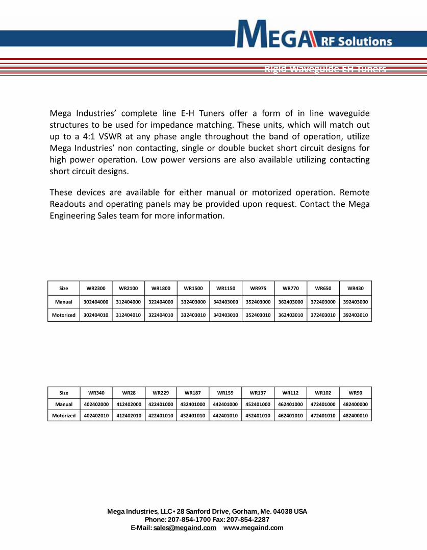
Mega Industries’ complete line E‐H Tuners offer a form of in line waveguide structures to be used for impedance matching. These units, which will match out up to a 4:1 VSWR at any phase angle throughout the band of opera on, u lize Mega Industries’ non contac ng, single or double bucket short circuit designs for high power opera on. Low power versions are also available u lizing contac ng short circuit designs.
These devices are available for either manual or motorized opera on. Remote Readouts and opera ng panels may be provided upon request. Contact the Mega Engineering Sales team for more informa on.
Size WR2300 WR2100 WR1800 WR1500 WR1150 WR975 WR770 WR650 WR430
Manual 302404000 312404000 322404000 332403000 342403000 352403000 362403000 372403000 392403000
Motorized 302404010 312404010 322404010 332403010 342403010 352403010 362403010 372403010 392403010
Size WR340 WR28 WR229 WR187 WR159 WR137 WR112 WR102 WR90
Manual 402402000 412402000 422401000 432401000 442401000 452401000 462401000 472401000 482400000
Motorized 402402010 412402010 422401010 432401010 442401010 452401010 462401010 472401010 482400010
Rigid Waveguide EH Tuners

Mega Industries, LLC • 28 Sanford Drive, Gorham, Me. 04038 USA
Phone: 207-854-1700 Fax: 207-854-2287 E-Mail: [email protected] www.megaind.com
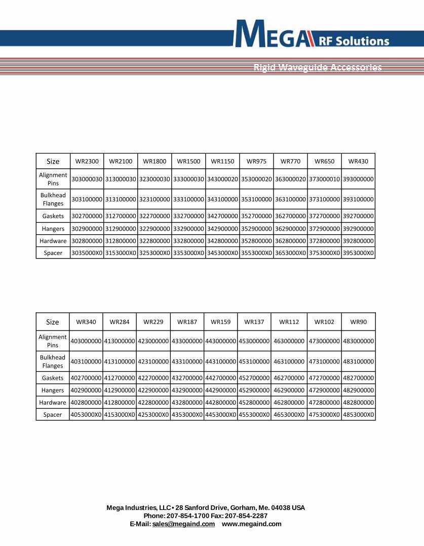
Rigid Waveguide Accessories
Mega Industries has all the accessories needed for the installa on of waveguide components. Gaskets provide the proper electrical and mechanical seal for interior and exterior use. Each hardware kit contains stainless steel hex bolts, flat washers, lock washers and nuts for a complete waveguide flange joint. Mega can also provide waveguide spacers that meet EIA specifica ons, bulkhead flanges and hangers.
Mega Industries, LLC • 28 Sanford Drive, Gorham, Me. 04038 USA
Phone: 207-854-1700 Fax: 207-854-2287 E-Mail: [email protected] www.megaind.com
Size WR2300 WR2100 WR1800 WR1500 WR1150 WR975
Alignment Pins
303000030 313000030 323000030 333000030 343000020 353000020
Bulkhead Flanges
303100000 313100000 323100000 333100000 343100000 353100000
Gaskets 302700000 312700000 322700000 332700000 342700000 352700000
Hangers 302900000 312900000 322900000 332900000 342900000 352900000
Hardware 302800000 312800000 322800000 332800000 342800000 352800000
WR770
363000020
363100000
362700000
362900000
362800000
WR430
393000000
393100000
392700000
392900000
392800000
WR650
373000010
373100000
372700000
372900000
372800000
Spacer 3035000X0 3153000X0 3253000X0 3353000X0 3453000X0 3553000X0 3653000X0 3753000X0 3953000X0
Size WR340 WR284 WR229 WR187 WR159 WR137
Alignment Pins
403000000 413000000 423000000 433000000 443000000 453000000
Bulkhead Flanges
403100000 413100000 423100000 433100000 443100000 453100000
Gaskets 402700000 412700000 422700000 432700000 442700000 452700000
Hangers 402900000 412900000 422900000 432900000 442900000 452900000
Hardware 402800000 412800000 422800000 432800000 442800000 452800000
WR112
463000000
463100000
462700000
462900000
462800000
WR90
483000000
483100000
482700000
482900000
482800000
WR102
473000000
473100000
472700000
472900000
472800000
Spacer 4053000X0 4153000X0 4253000X0 4353000X0 4453000X0 4553000X0 4653000X0 4753000X0 4853000X0
Rigid Waveguide Accessories

Mega Industries, LLC • 28 Sanford Drive, Gorham, Me. 04038 USA
Phone: 207-854-1700 Fax: 207-854-2287 E-Mail: [email protected] www.megaind.com
DUMMY LOADS
I N T R O D U C T I O N DEFINITION: A dummy load is a high power single terminal device intended to terminate a transmission line. They are pri-marily employed to test high power microwave systems at full power capacity. DISSIPATIVE MATERIAL: Three types of dissipative mate-rial are employed in Mega Industries’ dummy loads: (1) lossy plastic, (2) refractory ceramic, and (3) water. The lossy plastic consists of particles of lossy material suspend-ed in plastic medium. This material may be designed to provide various attenuations per unit length but is limited as to operat-ing temperature. It is employed primarily for low frequency and low power applications. The refractory material is a rugged substance that may be oper-ated at temperatures up to 1600°F. It is virtually incapable of being machined and consequently must be fired in finished form. Such material is employed in most high power applications. The dissipative properties of water are also employed for dum-my load applications. Energy from the guide is coupled through a leaky wall to the water which flows alongside the main guide. Water loads are employed for extremely high power and calori-metric applications. HEAT TRANSFER: Three methods of heat transfer are em-ployed: (1) free air convection, (2) forced air cooling, and (3) liquid cooling. Free air convection loads transfer heat by means of cooler air in contact with the load and by radiation from the black outer sur-face. Such loads may be provided with fins to increase the outer surface area and thus the heat transfer. Forced air cooled loads provide much greater heat transfer and power ratings than standard convection cooled units. Our ap-plication engineers are prepared to assist in determining proper specifications for forced air models. Liquid cooled loads utilize flowing water or other coolants to increase heat transfer. The coolant is passed in direct contact with the load housing to optimize heat flow.
FREQUENCY RANGES: The exact operating frequency range of each dummy load should be specified on each order or in-quiry. While dummy loads can be supplied to operate over full waveguide bands, generally faster delivery and a more economi-cal unit can be furnished for use over narrower frequency rang-es. POWER RATINGS: The power rating of a dummy load is a complex function dependent upon many parameters. Average and peak power, guide pressure, external temperature, guide size, air flow, and availability of auxiliary coolant all play factors in the final power rating of a dummy load. The average and peak powers are interrelated in that the peak power capacity is a function of the operating temperature which in turn is a function of the average power. These are then impacted by the ambient temperature of the cooling medium (air or water). The tables on the following pages provide power ratings for each model. The independent average power rating assumes CW operation. The independent peak power rating assumes negligible average power. The typical combined average and peak power ratings should be employed in combination. Our application engineers will readily assist in determining proper loads for a particular application. HIGHER POWERS: Mega can supply dummy loads with higher power ratings on request. Longitudinal fins, forced air cooling, and other techniques are also employed to improve high power performance. FINISH: Air cooled high power dummy loads have high surface temperatures and must be finished in such a manner as to in-crease heat transfer. Mega employs a heat resistant black sili-cone-based paint (>525°C) for most applications, although cus-tom finishes are available for even higher surface temperatures. DA LOADS: Mega can supply DA loads per MIL-D-3954C. These DA loads are identical to the WF series in all electrical and mechanical respects except that they are supplied with elec-trical testing certification and a nameplate per MIL-D-3954C.
SPECIAL DESIGN The following table indicates the information required for the design of special loads. These parameters are closely interrelated. Any-one specification may be optimized; however, this generally requires the relaxation of other specifications. Our application engineers would be pleased to assist in determining proper specifications for your system application. ELECTRICAL MECHANICAL ENVIRONMENTAL Frequency Range Connectors or Flanges Temperature Maximum VSWR Dimensions Coolant Flow Average Power Weight Coolant Temperature Peak Power Finish Humidity Guide Pressure Marking Shock Other Mounting Provision Vibration Coolant Altitude Coolant Pressure Other Other

Mega Industries, LLC • 28 Sanford Drive, Gorham, Me. 04038 USA
Phone: 207-854-1700 Fax: 207-854-2287 E-Mail: [email protected] www.megaind.com
7.50 – 11.50 GHz
WD and WZ series Dummy Loads and Load Inserts
Extremely Rugged High Power Loads High Temperature Refractory Load Elements
Mega WD series dummy loads are low cost, miniaturized units with moderate power handling capacity. Models are designed for bands from 7.50 to 11.50 GHz.
The WD loads employ tapered refractory load elements which are capable of withstanding extremely high temperature. These loads are sometimes used as 1 Watt terminations at ambient temperatures as high as 600°F. They are designed to provide optimum performance over ap-proximately 12% frequency bands. Cover flanges are supplied.
The Mega WZ series consists of the tapered refractory load ele-ments as used in the WD series. They can be cemented by the user into a section of waveguide to meet particular requirements.
The table provides power ratings for each model. Independent aver-age power rating assumes CW operation, and independent peak power rating assumes negligible average power. The combined average and peak power ratings should be employed together.
General Specifications: Load Material: Refractory Test Pressure: 35 psig. max. Housing Finish: Black, Silicone-based Pyromark 1200 >525°C (1,000°F) Material: Aluminum Flange Finish: RoHS Compliant
Other Waveguide Loads: Unfinned Loads: WE series Finned Loads: WF series Superfinned Loads: WG series Liquid Cooled Loads: WL series
Model Frequency Range
Waveguide Size
Power Ratings Approximate Dimensions inches/ounces Independent* Combined
RG WR W Avg.
kW pk @ 40 psig
W Avg.
kW pk @ 30 psig
L in.
W in.
H in.
Wt. oz.
WD-0052 7.50-8.50 68 112 150 100 60 60 2.2 1.9 1.9 2.5
WD-0053 8.50-9.60
WD-0056 8.50-9.60
67 90 100 75 40 40 1.9 1.7 1.7 2.5 WD-0057 9.50-10.60
WD-0058 10.30-11.50
WZ-0052 7.50-8.50 68 112 100
15 15‡ 2.0 1.122 0.497 0.5
WZ-0053 8.50-9.60
WZ-0056 8.50-9.60
67 90 60
10 10‡ 1.6 0.900 0.400 0.2 WZ-0057 9.50-10.60
WZ-0058 10.30-11.50
Mega Industries, LLC • 28 Sanford Drive, Gorham, Me. 04038 USA
Phone: 207-854-1700 Fax: 207-854-2287 E-Mail: [email protected] www.megaind.com
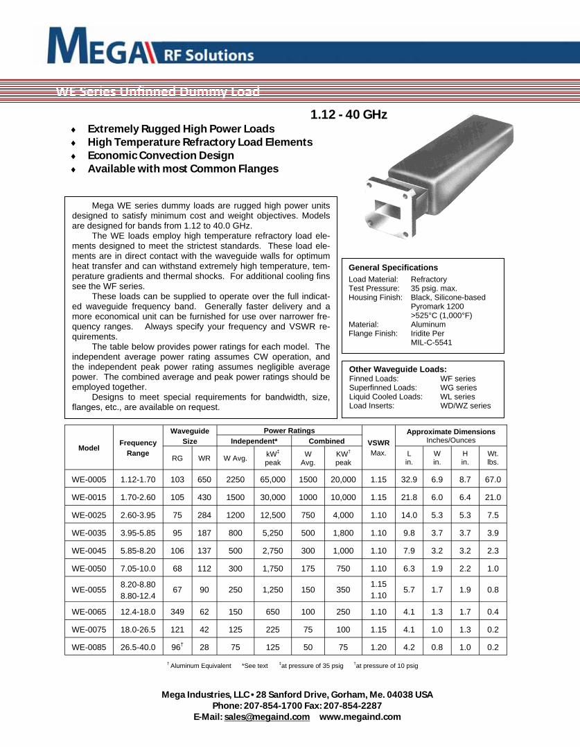
1.12 - 40 GHz Extremely Rugged High Power Loads High Temperature Refractory Load Elements Economic Convection Design Available with most Common Flanges
Mega WE series dummy loads are rugged high power units designed to satisfy minimum cost and weight objectives. Models are designed for bands from 1.12 to 40.0 GHz.
The WE loads employ high temperature refractory load ele-ments designed to meet the strictest standards. These load ele-ments are in direct contact with the waveguide walls for optimum heat transfer and can withstand extremely high temperature, tem-perature gradients and thermal shocks. For additional cooling fins see the WF series.
These loads can be supplied to operate over the full indicat-ed waveguide frequency band. Generally faster delivery and a more economical unit can be furnished for use over narrower fre-quency ranges. Always specify your frequency and VSWR re-quirements.
The table below provides power ratings for each model. The independent average power rating assumes CW operation, and the independent peak power rating assumes negligible average power. The combined average and peak power ratings should be employed together.
Designs to meet special requirements for bandwidth, size, flanges, etc., are available on request.
General Specifications
Load Material: Refractory Test Pressure: 35 psig. max. Housing Finish: Black, Silicone-based Pyromark 1200 >525°C (1,000°F) Material: Aluminum Flange Finish: Iridite Per MIL-C-5541
Other Waveguide Loads: Finned Loads: WF series Superfinned Loads: WG series Liquid Cooled Loads: WL series Load Inserts: WD/WZ series
Model Frequency
Range
Waveguide Size
Power Ratings VSWR Max.
Approximate Dimensions Inches/Ounces Independent* Combined
RG WR W Avg. kW‡ peak
W Avg.
KW† peak
L in.
W in.
H in.
Wt. lbs.
WE-0005 1.12-1.70 103 650 2250 65,000 1500 20,000 1.15 32.9 6.9 8.7 67.0
WE-0015 1.70-2.60 105 430 1500 30,000 1000 10,000 1.15 21.8 6.0 6.4 21.0
WE-0025 2.60-3.95 75 284 1200 12,500 750 4,000 1.10 14.0 5.3 5.3 7.5
WE-0035 3.95-5.85 95 187 800 5,250 500 1,800 1.10 9.8 3.7 3.7 3.9
WE-0045 5.85-8.20 106 137 500 2,750 300 1,000 1.10 7.9 3.2 3.2 2.3
WE-0050 7.05-10.0 68 112 300 1,750 175 750 1.10 6.3 1.9 2.2 1.0
WE-0055 8.20-8.80 8.80-12.4
67 90 250 1,250 150 350 1.15 1.10
5.7 1.7 1.9 0.8
WE-0065 12.4-18.0 349 62 150 650 100 250 1.10 4.1 1.3 1.7 0.4
WE-0075 18.0-26.5 121 42 125 225 75 100 1.15 4.1 1.0 1.3 0.2
WE-0085 26.5-40.0 96† 28 75 125 50 75 1.20 4.2 0.8 1.0 0.2
† Aluminum Equivalent *See text ‡at pressure of 35 psig †at pressure of 10 psig
WE Series Unfinned Dummy Load

Mega Industries, LLC • 28 Sanford Drive, Gorham, Me. 04038 USA
Phone: 207-854-1700 Fax: 207-854-2287 E-Mail: [email protected] www.megaind.com
WF Series Finned Dummy Load
1.12 - 40 GHz Extremely Rugged High Power Loads High Temperature Refractory Load Elements Transverse Cooling Fins Available with most Common Flanges
General Specifications Load Material: Refractory Test Pressure: 35 psig. max. Housing Finish: Black, Silicone-based Pyromark 1200 >525°C (1,000°F) Flange Type: <2.6 GHz: Contact >2.6 GHz Flange Cover Material: Aluminum Flange Finish: Iridite Per MIL-C-5541
Mega WF series dummy loads are rugged commercial loads for use in the harshest environments. This model is designed to meet tight electrical and mechanical specifications for bands from 1.12 to 40.0 GHz.
The WF loads employ heavy duty transverse cooling fins and high temperature refractory load elements designed to deliver reliable performance. The load elements are in direct contact with the wave-guide walls for optimum heat transfer and can withstand extremely high temperature, temperature gradients and thermal shocks. The WG series is a similar finned design, but with additional fins for en-hanced heat transfer. For lower powers, unfinned models may meet the need and the WE series can be used.
These loads can be supplied to operate over the full indicated waveguide frequency band. Generally faster delivery and a more economical unit can be furnished for use over narrower frequency ranges. Always specify your frequency and VSWR requirements with any request.
Designs to meet special requirements for bandwidth, size, flang-es, etc., are available on request.
Other Waveguide Loads: Unfinned Loads: WE series Superfinned Loads: WG series Liquid Cooled Loads: WL series Load Inserts: WD/WZ series
Model Frequency
Range
Waveguide Size
Rated Power* VSWR Max.
Approximate Dimensions Inches/lbs.
RG WR W Avg.
Test kW pk
L in.
W in.
H in.
Wt. lbs.
WF-0005 1.12-1.70 103 650 8000 2200 1.15 32.9 8.9 11.4 90.0
WF-0025 2.60-3.95 75 284 4500 3200 1.10 14.0 4.9 6.4 11.5
WF-0035 3.95-5.85 95 187 2000 1000 1.10 9.8 3.6 4.1 5.1
WF-0045 5.85-8.20 106 137 1000 710 1.10 8.0 3.1 3.9 3.3
WF-0050 7.05-10.0 68 112 600 460 1.10 6.3 2.5 3.1 1.5
WF-0055 8.20-8.80 8.80-12.4 67 90 500 290 1.15
1.10 5.7 2.8 2.8 1.3
WF-0065 12.4-18.0 349 62 250 160 1.15 4.3 2.4 2.4 0.75
WF-0075 18.0-26.5 121 42 150 80 1.15 4.2 2.2 2.2 0.37
WF-0085 26.5-40.0 96† 28 75 100 1.20 4.2 2.0 2.0 0.37
WE-0015 1.70-2.60 105 430 5300 1000 1.15 21.8 8.0 8.9 40.0
† Aluminum Equivalent *When tested in accordance with MIL-D-3954C

Mega Industries, LLC • 28 Sanford Drive, Gorham, Me. 04038 USA
Phone: 207-854-1700 Fax: 207-854-2287 E-Mail: [email protected] www.megaind.com
Highest Power Air Cooled Loads High Temperature Refractory Load Elements Transverse Cooling Fins Available with most Common Flanges
Mega WG series dummy loads are designed to offer superior performance that
exceeds that offered by the standard military DA loads. Improved fin location, slight
physical size alterations, and other enhancements make this increase in performance
possible.
The WG loads employ transverse cooling fins and high temperature refractory
load elements that are designed to conform to the rigorous requirements of demanding
environments with high vibration and wide temperature swings. These load elements
are in direct contact with the waveguide walls for optimum heat transfer. They can
withstand extremely high temperature, temperature gradients and thermal shocks.
These loads can be supplied to operate over the full indicated waveguide
frequency band. Generally faster delivery and a more economical unit can be
furnished for use over narrower frequency ranges. Always specify your frequency and
VSWR requirements with any request.
Designs to meet special requirements for bandwidth, size, flanges, etc., are
available on request.
Power Ratings: The Independent Average Power ratings assume CW operation
and the Independent Peak Power ratings assume negligible average power. The
Combined Power ratings should be employed together. Forced air cooling is
necessary to reach the highest levels listed.
General Specifications: Load Material: Refractory Test Pressure: 35 psig. max. Housing Finish: Black, Silicone-based Pyromark 1200 >525°C (1,000°F) Flange Type: <2.6 GHz: Contact >2.6 GHz Flange Cover Material: Aluminum Flange Finish: Iridite per MIL-C-5541
Other Waveguide Loads: Unfinned Loads: WE series Finned Loads: WF series Liquid Cooled Loads: WL series Mini and Load Inserts: WD/WZ series
Model Frequency
Range TYPE
Waveguide Size
Absolute Max Independent Power
Rating* VSWR Max.
Approximate Dimensions
RG WR W Avg. Peak @ 45psig (kW)
Average (W)
Peak @ 30psig (kW)
L in.
W in.
H in.
Wt. lbs.
WG-0005 1.12-1.70 I 103 650 9000 100,000 6000 20,000 1.15 37.6 8.9 11.4 91.0
WG-0015 1.70-2.60 II 105 430 6500 45,000 5000 10,000 1.15 24.4 6.7 8.8 30.0
WG-0025 2.60-3.95 II 75 284 5000 19,000 4000 4,000 1.10 16.6 5.4 6.4 12.0
WG-0035 3.95-5.85 II 95 187 2500 7,750 1800 1,800 1.10 12.2 3.6 4.1 5.5
WG-0045 5.85-8.20 II 106 137 1500 4,250 1000 1,000 1.10 9.5 3.1 3.9 3.5
WG-0050 7.05-10.0 II 68 112 750 2,750 600 750 1.10 7.9 2.5 3.1 1.7
WG-0055 8.20-8.80 8.80-12.4
II 67 90 650 1,750 500 350 1.15
1.10 6.7 2.8 2.8 1.4
WG-0065 12.40-18.00 II 91† 62 400 1,000 250 250 1.10 4.7 2.4 2.4 0.75
WG-0075 18.00-26.50 III 121 42 300 350 150 100 1.15 4.5 2.2 2.2 0.37
WG-0085 26.50-40.00 III 96† 28 300 175 100 75 1.15 4.5 2.0 2.0 0.37
Typical Combined Power Rating*
† Aluminum Equivalent *When tested in accordance with MIL-D-3954C
WG Series High Power Finned Dummy Load

Mega Industries, LLC • 28 Sanford Drive, Gorham, Me. 04038 USA
Phone: 207-854-1700 Fax: 207-854-2287 E-Mail: [email protected] www.megaind.com
Maximum Power Water Cooled Loads High Temperature Refractory Load Elements Mounts in Any Position Available with most Common Flanges
General Specifications
VSWR: 1.10:1 max.
Coolant: Liquid
Load Material: Refractory
Coolant:
Max. Inlet Temp: 150°F
Test Pressure: 50 psig. max.
Pressure: 100 psig max.
Coolant Connector: NPT, female
WL-0025, -0035, -0045: ¾ - 14
WL-0050, -0055, -0065: ¼ - 18 Finish: Black, Silicone-based Pyromark 1200 >525°C (1,000°F)
Flange Material: Aluminum
Flange Finish: Iridite
per MIL-C-5541
Other Waveguide Loads: Unfinned Loads: WE series
Finned Loads: WF series
Super-Finned Loads: WG series
Mini and Load Inserts: WD/WZ series
Model Frequency
Range
Waveguide Size
Absolute Max Independent Power
Rating* Typical Combined
Power Rating* Min. Flow Rate (gpm)
VSWR Max.
Approximate Dimensions
RG WR W Avg. Peak @ 45psig (kW)
Average (W)
Peak @ 30psig (kW)
L in.
Diam. in.
Wt. lbs.
WL-0005 1.12-1.70 103 650 25,000 100,000 12,000 20,000 8 1.15 40.0 9.5 95
WL-0015 1.70-2.60 105 430 18,000 45,000 10,000 10,000 7 1.15 28.5 7.7 45
WL-0025 2.60-3.95 75 284 15,000 19,000 7,500 4,000 5 1.10 17.5 5.9 19
WL-0035 3.95-5.85 95 187 10,000 7,750 4,000 1,800 4 1.10 12.6 4.8 10
WL-0045 5.85-8.20 106 137 5,000 4,250 2,000 1,000 2 1.10 9.0 3.4 4
WL-0050 7.05-10.0 68 112 4,000 2,750 1,500 750 2 1.10 8.1 3.1 3
WL-0055 8.80-12.40† 67 90 3,000 1,750 1,000 350 1 1.10 7.0 2.9 2.3
WL-0065 12.40-18.00 349 62 1,500 1,000 500 250 1 1.10 5.8 2.5 1.3
† Aluminum Equivalent *When tested in accordance with MIL-D-3954C
Mega WL series dummy loads are the highest power liquid cooled dry loads available in this product family. They are available in the 1.12 to 18.0 GHz region.
The WL dummy loads employ high temperature refractory load elements designed to meet the most demanding requirements. Load elements are in direct contact with waveguide walls for optimum heat transfer. They can withstand extremely high temperature, temperature gradients, and thermal shocks. They are designed to operate at the rated power without coolant for sufficient time to permit detection and correction of coolant system failure.
The units utilize a cylindrical aluminum, copper or stainless steel cooling jacket. Stiffening ribs are employed for mechanical rigidity, improved heat transfer, and optimum coolant flow. Water is used as a coolant. Standard NPT female pipe threads are provided for coolant connections. Coolant flow rates shown are the minimum recommended for proper cooling for peak power values. These units may be mounted in any position but care must be taken to remove trapped air during operation.
These loads can be supplied to operate at set frequencies or the full indicated waveguide frequency band. Generally faster delivery and a more economical unit can be furnished for use over narrower frequency ranges. Always specify your frequency and VSWR requirements.
The table provides power ratings for each model. The independent average power rating assumes CW operation, and the independent peak power rating assumes negligible average power. The combined average and peak power ratings should be employed together. Additional water flow volumes may be necessary to reach the highest levels listed or if inlet temperatures are above 20 degrees C.
WL Series Water Cooled High Power Dummy Load

Mega Industries, LLC • 28 Sanford Drive, Gorham, Me. 04038 USA
Phone: 207-854-1700 Fax: 207-854-2287 E-Mail: [email protected] www.megaind.com
Mega Custom Dummy Loads are rugged commercial loads for use in the harshest environments and custom designed to fit in the most demanding of locations. With cooling fins or liquid jackets, they can contain several completely isolated load elements, include customer specified mounting for thermally sensitive electronics and embody any mounting or vibration isolation scheme you can dream up. With load elements from 1.12 GHz to 40 GHz, there is no problem too tough to tackle.
DUAL WAVEGUIDE DUMMY LOAD
FULLY ISOLATED WAVEGUIDE INPUTS
ELECTRONIC MOUNTING INTEGRATED INTO HEATSINK
VIBRATION DAMPING MOUNTING PAD
Custom Designed Dummy Loads


Mega Industries, LLC • 28 Sanford Drive, Gorham, Me. 04038 USA
Phone: 207-854-1700 Fax: 207-854-2287 E-Mail: [email protected] www.megaind.com
Semi‐Flexible Waveguide

Mega Industries, LLC • 28 Sanford Drive, Gorham, Me. 04038 USA
Phone: 207-854-1700 Fax: 207-854-2287 E-Mail: [email protected] www.megaind.com
Mega Industries, LLC manufactures semi‐flexible waveguide products in sizes WR90 thru WR2300. All designs are field proven to meet the highest standards in the industry. Flexible waveguides are manufactured from aluminum or copper alloys to meet EIA and Military specifica ons and may be plated in accordance with customer requirements. Standard finish is a Chemical Resistant Epoxy paint system. Urethane and neoprene jacke ng systems are also offered.
Mega Industries recommends the use of flexible waveguide sec ons to account for system flange misalignments and also for interfaces where expansion and contrac on in a microwave feed must be absorbed. Half height flexible waveguides are also available is some popular sizes and custom flexible waveguide sizes are available upon request.

Mega Industries, LLC • 28 Sanford Drive, Gorham, Me. 04038 USA
Phone: 207-854-1700 Fax: 207-854-2287 E-Mail: [email protected] www.megaind.com
Mega Industries Flexible Waveguide Offsets excellent electrical performance while giving you that extra flexibility that you need in those ght connec ons that your layout may demand.
Semi‐Flexible Offsets
Size WR2300 WR2100 WR1800 WR1500 WR1150 WR975 WR770 WR650 WR430
Aluminum 3064000X0 3164000X0 3264000X0 3364010X0 3464010X0 3564010X0 3664000X0
Phos. Bronze
Brass 3764110X0 3964140X0
Size WR340 WR284 WR229 WR187 WR159 WR137 WR112 WR102 WR90
Aluminum
Phos. Bronze 4064240X0 4164250X0 4264280X0 4364250X0 4464270X0 4564270X0 4764270X0 4864290X0
Brass 4664170X0
Size WR2300 WR2100 WR1800 WR1500 WR1150 WR975 WR770 WR650 WR430
Aluminum 3065000X0 3165000X0 3265000X0 3365010X0 3465010X0 3565010X0 3665000X0
Phos. Bronze
Brass 3765110X0 3965140X0
Size WR340 WR284 WR229 WR187 WR159 WR137 WR112 WR102 WR90
Aluminum
Phos. Bronze 4065240X0 4165250X0 4265280X0 4365250X0 4465270X0 4565270X0 4765270X0 4865290X0
Brass 4665170X0
E‐Plane
H‐Plane

Mega Industries, LLC • 28 Sanford Drive, Gorham, Me. 04038 USA
Phone: 207-854-1700 Fax: 207-854-2287 E-Mail: [email protected] www.megaind.com
Semi‐Flexible Sweeps
Mega manufactures Flexible Waveguide Sweeps from various materials and various flange configura ons. Mega provides full design services for factory formed sweeps that assure accuracy and electrical performance.
Size WR2300 WR2100 WR1800 WR1500 WR1150 WR975 WR770 WR650 WR430
Aluminum 30630000 316300000 326300000 336301000 346301000 356301000 366300000
Phos. Bronze
Brass 376311000 396314000
Size WR2300 WR2100 WR1800 WR1500 WR1150 WR975 WR770 WR650 WR430
Aluminum 30620000 316200000 326200000 336201000 346201000 356201000 366200000
Phos. Bronze
Brass 376211000 396214000
Size WR340 WR284 WR229 WR187 WR159 WR137 WR112 WR102 WR90
Aluminum
Phos. Bronze 406224000 416225000 426228000 436225000 446227000 456227000 476227000 486229000
Brass 466217000
Size WR340 WR284 WR229 WR187 WR159 WR137 WR112 WR102 WR90
Aluminum
Phos. Bronze 406324000 416325000 426328000 436325000 446327000 456327000 476327000 486329000
Brass 466317000
E‐Plane
H‐Plane
Mega Industries, LLC • 28 Sanford Drive, Gorham, Me. 04038 USA
Phone: 207-854-1700 Fax: 207-854-2287 E-Mail: [email protected] www.megaind.com
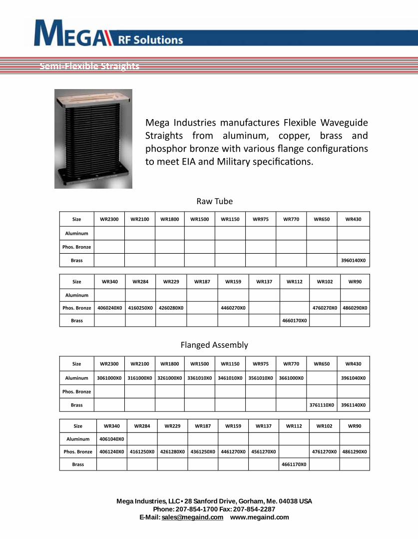
Semi‐Flexible Straights
Mega Industries manufactures Flexible Waveguide Straights from aluminum, copper, brass and phosphor bronze with various flange configura ons to meet EIA and Military specifica ons.
Size WR2300 WR2100 WR1800 WR1500 WR1150 WR975 WR770 WR650 WR430
Aluminum
Phos. Bronze
Brass 3960140X0
Size WR2300 WR2100 WR1800 WR1500 WR1150 WR975 WR770 WR650 WR430
Aluminum 3061000X0 3161000X0 3261000X0 3361010X0 3461010X0 3561010X0 3661000X0 3961040X0
Phos. Bronze
Brass 3761110X0 3961140X0
Size WR340 WR284 WR229 WR187 WR159 WR137 WR112 WR102 WR90
Aluminum
Phos. Bronze 4060240X0 4160250X0 4260280X0 4460270X0 4760270X0 4860290X0
Brass 4660170X0
Size WR340 WR284 WR229 WR187 WR159 WR137 WR112 WR102 WR90
Aluminum 4061040X0
Phos. Bronze 4061240X0 4161250X0 4261280X0 4361250X0 4461270X0 4561270X0 4761270X0 4861290X0
Brass 4661170X0
Raw Tube
Flanged Assembly

Mega Industries, LLC • 28 Sanford Drive, Gorham, Me. 04038 USA
Phone: 207-854-1700 Fax: 207-854-2287 E-Mail: [email protected] www.megaind.com
Semi‐Flexible Twists
Mega Industries manufactures Flexible Waveguide Twists from aluminum, copper brass and phosphor bronze with various flange configura ons.
Mega provides a full design services to assure accuracy and electrical performance.
Size WR2300 WR2100 WR1800 WR1500 WR1150 WR975 WR770 WR650 WR430
Right Hand 3066000X0 3166000X0 3266010X0 3366010X0 3466010X0 3566010X0 3666000X0 3766000X0 3966040X0
Le Hand 3067000X0 3167000X0 3267010X0 3367010X0 3467010X0 3567010X0 3667000X0 3767000X0 3967040X0
Size WR340 WR284 WR229 WR187 WR159 WR137 WR112 WR102 WR90
Right Hand 4066040X0 4166250X0 4266280X0 4366250X0
Le Hand 4067040X0 4167250X0 4267280X0 4367250X0

Mega Industries, LLC • 28 Sanford Drive, Gorham, Me. 04038 USA
Phone: 207-854-1700 Fax: 207-854-2287 E-Mail: [email protected] www.megaind.com
Mega Industries, LLC • 28 Sanford Drive, Gorham, Me. 04038 USA
Phone: 207-854-1700 Fax: 207-854-2287 E-Mail: [email protected] www.megaind.com
Semi‐Flexible Waveguide Technical
Data

Mega Industries, LLC • 28 Sanford Drive, Gorham, Me. 04038 USA
Phone: 207-854-1700 Fax: 207-854-2287 E-Mail: [email protected] www.megaind.com
Typical Specifica ons
Typical Specifica ons
Size Frequency
Range (GHZ)
VSWR* A enua on**
Average Power
Peak Power
E‐Plane w/ Jacket
H‐Plane w/ Jacket
E‐Plane No Jacket
H‐Plane No Jacket
Kilowa s Mega‐wa s
WR90 8.20‐12.40 1.10 0.09 1.75 2.50 1.25 1.50 3 0.18
WR102 7.00‐11.00 1.10 0.08 2.00 2.88 1.30 1.94 4 0.30
WR112 7.05‐10.00 1.09 0.06 2.25 3.25 1.40 1.82 4 0.31
WR137 5.85‐8.20 1.09 0.05 2.38 3.38 1.50 2.07 5 0.50
WR159 4.90‐7.05 1.08 0.04 4.00 6.00 1.60 2.25 6 1.10
WR187 3.95‐5.85 1.08 0.03 4.38 6.50 1.94 3.00 6 1.25
WR229 3.30‐4.90 1.07 0.02 6.50 8.00 2.13 3.25 8 1.55
WR284 2.60‐3.95 1.09 0.02 7.00 9.50 2.94 5.50 10 2.00
WR340 2.20‐3.30 1.08 0.01 N/A N/A 4.25 6.00 16 3.70
WR430 1.70‐2.60 1.07 0.01 N/A N/A 6.00 8.00 20 4.70
WR510 1.45‐2.20 1.07 0.01 N/A N/A 6.00 12.00 20 4.70
WR650 1.12‐1.70 1.06 0.01 N/A N/A 6.00 12.00 150 11
WR770 .96‐1.45 1.05 0.01 N/A N/A 6.00 12.00 210 15
WR975 .75‐1.12 1.05 0.01 N/A N/A 9.00 18.00 350 25
WR1150 .64‐.96 1.05 0.01 N/A N/A 12.00 24.00 490 35
WR1500 .49‐.75 1.05 0.01 N/A N/A 12.00 30.00 840 60
WR1800 .41‐.62 1.05 0.01 N/A N/A 18.00 36.00 1200 86
WR2100 .35‐.53 1.05 0.01 N/A N/A 24.00 42.00 1300 117
WR2300 .32‐.49 1.05 0.01 N/A N/A 24.00 48.00 1540 141
Bend Radii to Centerline
* VSWR is per 2 foot sec on ** A enua on is in dB per foot
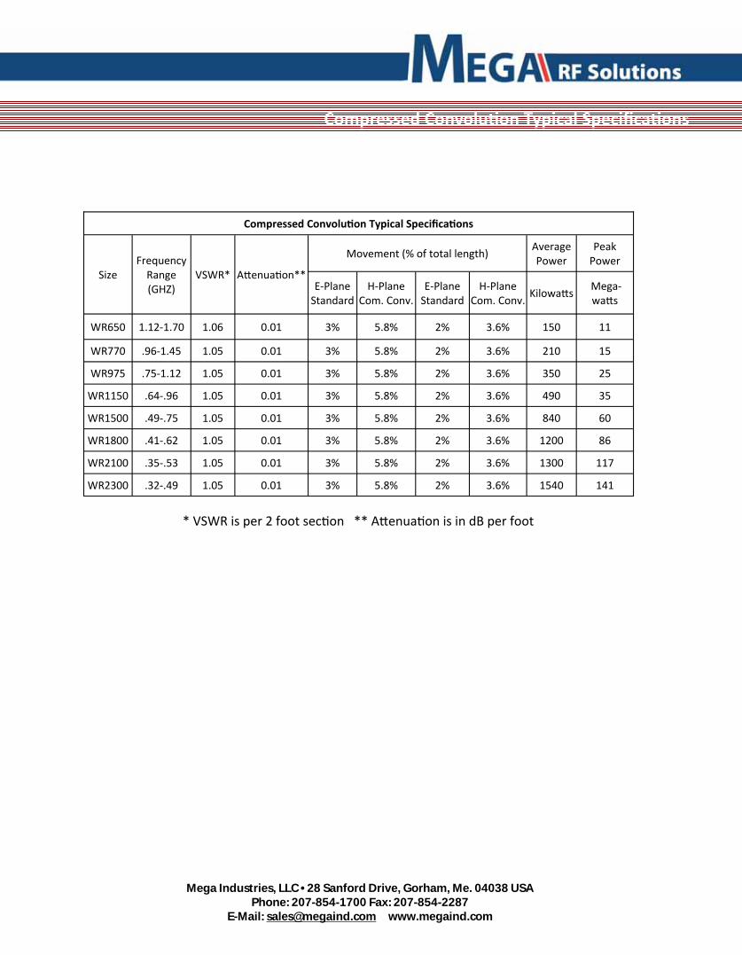
Mega Industries, LLC • 28 Sanford Drive, Gorham, Me. 04038 USA
Phone: 207-854-1700 Fax: 207-854-2287 E-Mail: [email protected] www.megaind.com
Compressed Convolu on Typical Specifica ons
Compressed Convolu on Typical Specifica ons
Size Frequency
Range (GHZ)
VSWR* A enua on**
Movement (% of total length) Average Power
Peak Power
E‐Plane Standard
H‐Plane Com. Conv.
E‐Plane Standard
H‐Plane Com. Conv.
Kilowa s Mega‐wa s
WR650 1.12‐1.70 1.06 0.01 3% 5.8% 2% 3.6% 150 11
WR770 .96‐1.45 1.05 0.01 3% 5.8% 2% 3.6% 210 15
WR975 .75‐1.12 1.05 0.01 3% 5.8% 2% 3.6% 350 25
WR1150 .64‐.96 1.05 0.01 3% 5.8% 2% 3.6% 490 35
WR1500 .49‐.75 1.05 0.01 3% 5.8% 2% 3.6% 840 60
WR1800 .41‐.62 1.05 0.01 3% 5.8% 2% 3.6% 1200 86
WR2100 .35‐.53 1.05 0.01 3% 5.8% 2% 3.6% 1300 117
WR2300 .32‐.49 1.05 0.01 3% 5.8% 2% 3.6% 1540 141
* VSWR is per 2 foot sec on ** A enua on is in dB per foot

Mega Industries, LLC • 28 Sanford Drive, Gorham, Me. 04038 USA
Phone: 207-854-1700 Fax: 207-854-2287 E-Mail: [email protected] www.megaind.com

Mega Industries, LLC • 28 Sanford Drive, Gorham, Me. 04038 USA
Phone: 207-854-1700 Fax: 207-854-2287 E-Mail: [email protected] www.megaind.com
Waveguide Technical
Data

Mega Industries, LLC • 28 Sanford Drive, Gorham, Me. 04038 USA
Phone: 207-854-1700 Fax: 207-854-2287 E-Mail: [email protected] www.megaind.com
A enua on Curves
The normal a enua on of a transmission line is the ra o of the output power to the input power when the load is matched to the characteris c impedance of the trans‐mission line. The common expression for normal a enua on in decibels is:
Where: P₂ = Power in wa s appearing at the output terminals of transmission line. P₁ = Power in wa s appearing at the input terminals of transmission line. For Mega Industries, rectangular aluminum alloy, 6061‐T6, air filled waveguides oper‐a ng over their respec ve standard EIA frequency bands, the theore cal a enua on is found by employing the following formula. Where: P = Power in wa s a = width of waveguide in inches b = height of waveguide in inches f = opera ng frequency fc = cutoff frequency of waveguide The a enua on curves are for standard waveguide and show 125% of theore cal a enua on which is used as a maximum value although measured values are signifi‐cantly less.
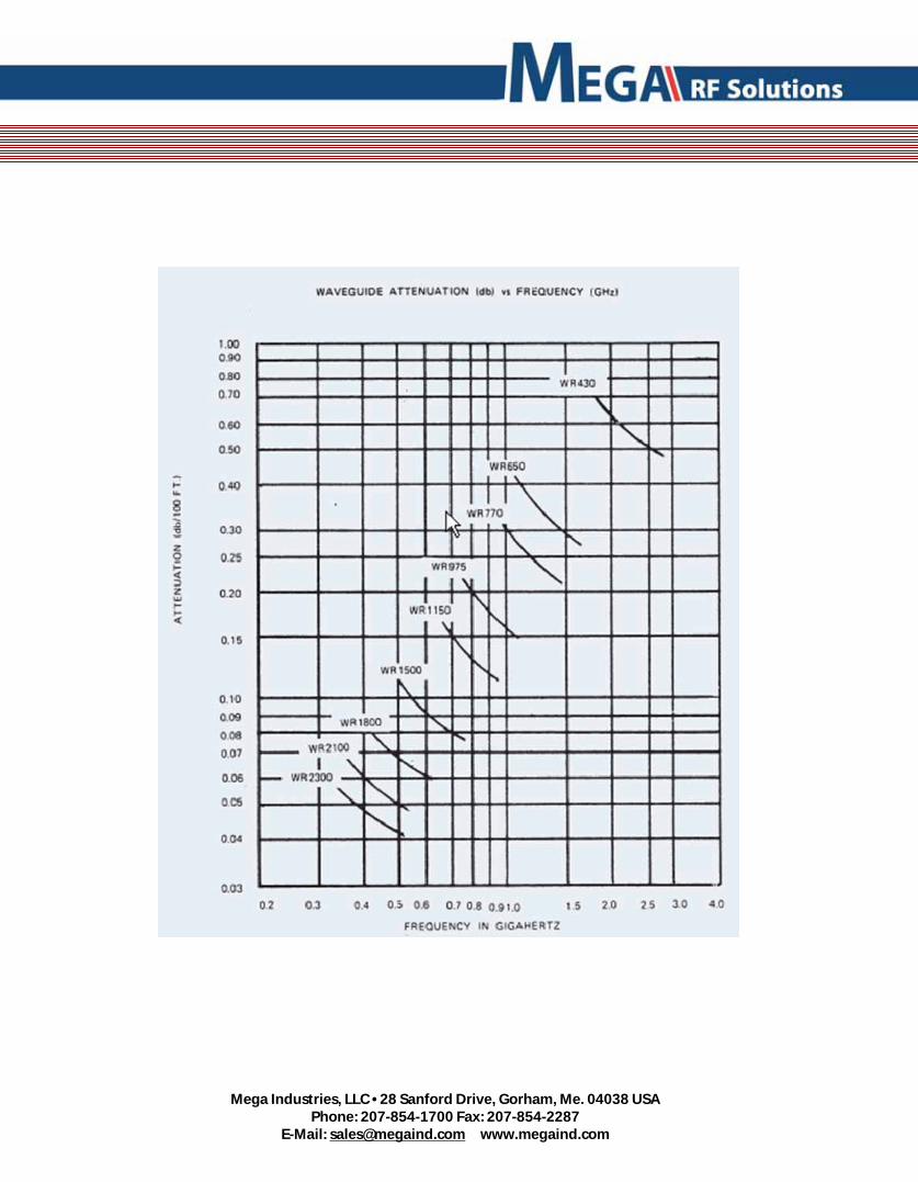
Mega Industries, LLC • 28 Sanford Drive, Gorham, Me. 04038 USA
Phone: 207-854-1700 Fax: 207-854-2287 E-Mail: [email protected] www.megaind.com
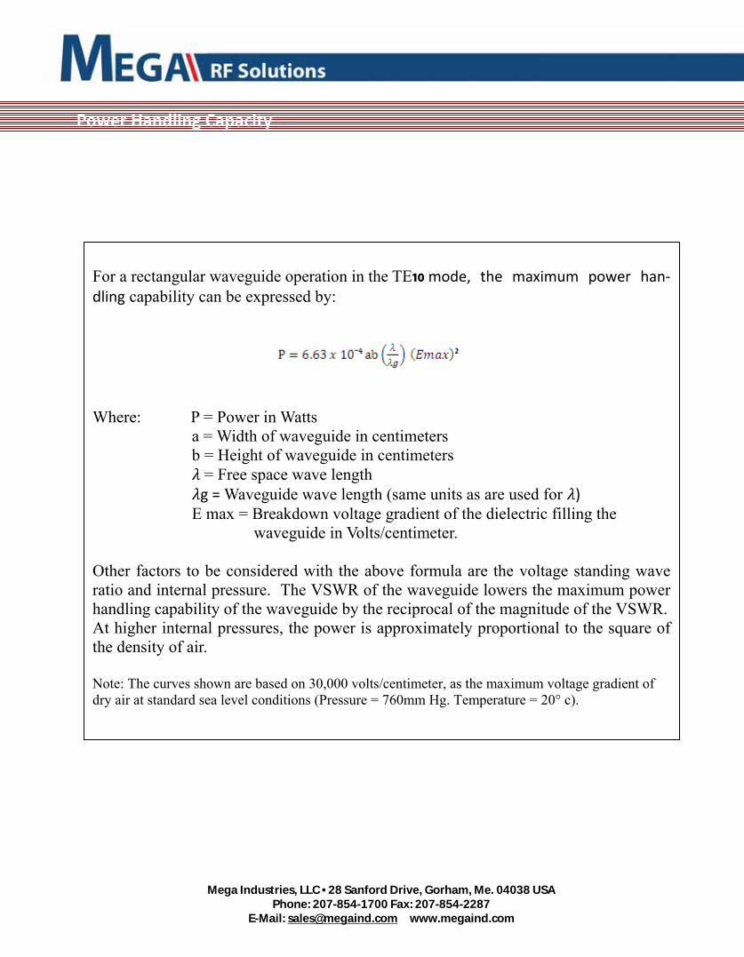
Mega Industries, LLC • 28 Sanford Drive, Gorham, Me. 04038 USA
Phone: 207-854-1700 Fax: 207-854-2287 E-Mail: [email protected] www.megaind.com
Power Handling Capacity
For a rectangular waveguide operation in the TE10 mode, the maximum power han‐dling capability can be expressed by:
Where: P = Power in Watts a = Width of waveguide in centimeters b = Height of waveguide in centimeters = Free space wave length g = Waveguide wave length (same units as are used for ) Ε max = Breakdown voltage gradient of the dielectric filling the waveguide in Volts/centimeter. Other factors to be considered with the above formula are the voltage standing wave ratio and internal pressure. The VSWR of the waveguide lowers the maximum power handling capability of the waveguide by the reciprocal of the magnitude of the VSWR. At higher internal pressures, the power is approximately proportional to the square of the density of air. Note: The curves shown are based on 30,000 volts/centimeter, as the maximum voltage gradient of dry air at standard sea level conditions (Pressure = 760mm Hg. Temperature = 20° c).
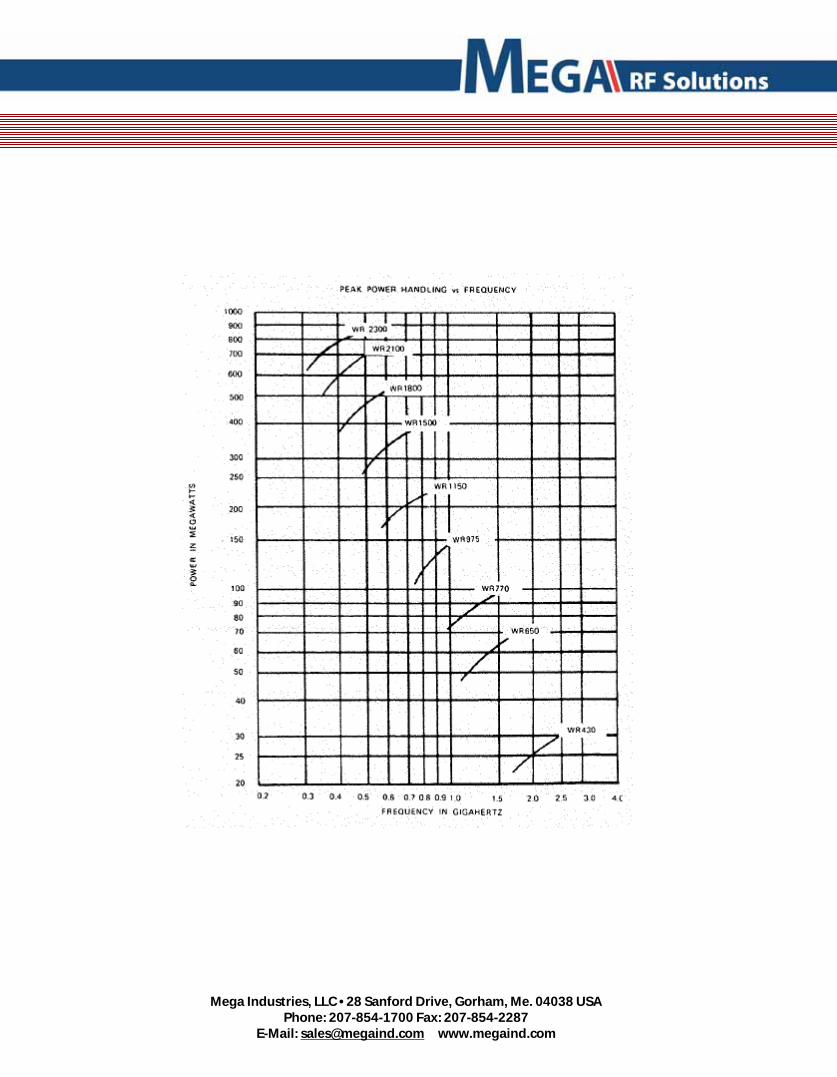
Mega Industries, LLC • 28 Sanford Drive, Gorham, Me. 04038 USA
Phone: 207-854-1700 Fax: 207-854-2287 E-Mail: [email protected] www.megaind.com
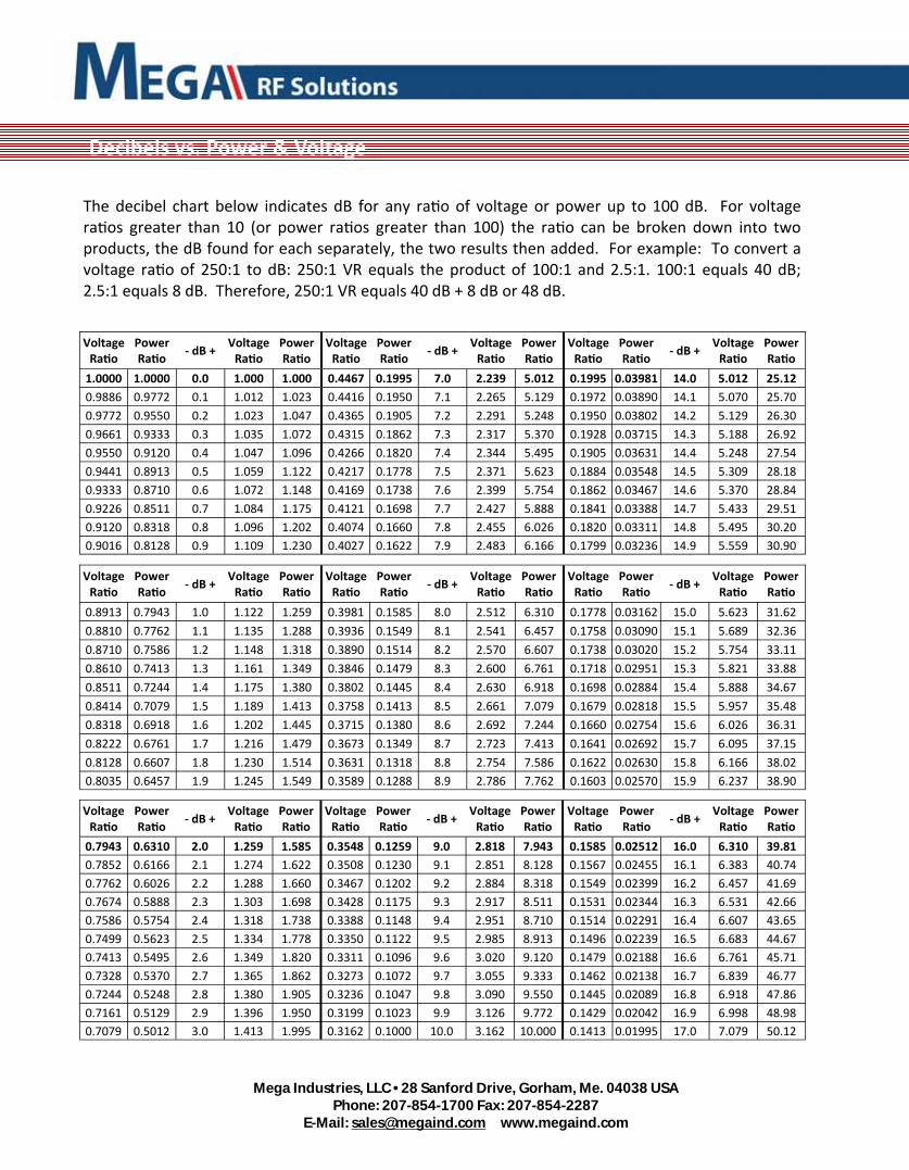
Mega Industries, LLC • 28 Sanford Drive, Gorham, Me. 04038 USA
Phone: 207-854-1700 Fax: 207-854-2287 E-Mail: [email protected] www.megaind.com
Decibels vs. Power & Voltage
Voltage Ra o
Power Ra o
‐ dB + Voltage Ra o
Power Ra o
Voltage Ra o
Power Ra o
‐ dB + Voltage Ra o
Power Ra o
Voltage Ra o
Power Ra o
‐ dB + Voltage Ra o
Power Ra o
1.0000 1.0000 0.0 1.000 1.000 0.4467 0.1995 7.0 2.239 5.012 0.1995 0.03981 14.0 5.012 25.12
0.9886 0.9772 0.1 1.012 1.023 0.4416 0.1950 7.1 2.265 5.129 0.1972 0.03890 14.1 5.070 25.70
0.9772 0.9550 0.2 1.023 1.047 0.4365 0.1905 7.2 2.291 5.248 0.1950 0.03802 14.2 5.129 26.30
0.9661 0.9333 0.3 1.035 1.072 0.4315 0.1862 7.3 2.317 5.370 0.1928 0.03715 14.3 5.188 26.92
0.9550 0.9120 0.4 1.047 1.096 0.4266 0.1820 7.4 2.344 5.495 0.1905 0.03631 14.4 5.248 27.54
0.9441 0.8913 0.5 1.059 1.122 0.4217 0.1778 7.5 2.371 5.623 0.1884 0.03548 14.5 5.309 28.18
0.9333 0.8710 0.6 1.072 1.148 0.4169 0.1738 7.6 2.399 5.754 0.1862 0.03467 14.6 5.370 28.84
0.9226 0.8511 0.7 1.084 1.175 0.4121 0.1698 7.7 2.427 5.888 0.1841 0.03388 14.7 5.433 29.51
0.9120 0.8318 0.8 1.096 1.202 0.4074 0.1660 7.8 2.455 6.026 0.1820 0.03311 14.8 5.495 30.20
0.9016 0.8128 0.9 1.109 1.230 0.4027 0.1622 7.9 2.483 6.166 0.1799 0.03236 14.9 5.559 30.90
Voltage Ra o
Power Ra o
‐ dB + Voltage Ra o
Power Ra o
Voltage Ra o
Power Ra o
‐ dB + Voltage Ra o
Power Ra o
Voltage Ra o
Power Ra o
‐ dB + Voltage Ra o
Power Ra o
0.8913 0.7943 1.0 1.122 1.259 0.3981 0.1585 8.0 2.512 6.310 0.1778 0.03162 15.0 5.623 31.62
0.8810 0.7762 1.1 1.135 1.288 0.3936 0.1549 8.1 2.541 6.457 0.1758 0.03090 15.1 5.689 32.36
0.8710 0.7586 1.2 1.148 1.318 0.3890 0.1514 8.2 2.570 6.607 0.1738 0.03020 15.2 5.754 33.11
0.8610 0.7413 1.3 1.161 1.349 0.3846 0.1479 8.3 2.600 6.761 0.1718 0.02951 15.3 5.821 33.88
0.8511 0.7244 1.4 1.175 1.380 0.3802 0.1445 8.4 2.630 6.918 0.1698 0.02884 15.4 5.888 34.67
0.8414 0.7079 1.5 1.189 1.413 0.3758 0.1413 8.5 2.661 7.079 0.1679 0.02818 15.5 5.957 35.48
0.8318 0.6918 1.6 1.202 1.445 0.3715 0.1380 8.6 2.692 7.244 0.1660 0.02754 15.6 6.026 36.31
0.8222 0.6761 1.7 1.216 1.479 0.3673 0.1349 8.7 2.723 7.413 0.1641 0.02692 15.7 6.095 37.15
0.8128 0.6607 1.8 1.230 1.514 0.3631 0.1318 8.8 2.754 7.586 0.1622 0.02630 15.8 6.166 38.02
0.8035 0.6457 1.9 1.245 1.549 0.3589 0.1288 8.9 2.786 7.762 0.1603 0.02570 15.9 6.237 38.90
Voltage Ra o
Power Ra o
‐ dB + Voltage Ra o
Power Ra o
Voltage Ra o
Power Ra o
‐ dB + Voltage Ra o
Power Ra o
Voltage Ra o
Power Ra o
‐ dB + Voltage Ra o
Power Ra o
0.7943 0.6310 2.0 1.259 1.585 0.3548 0.1259 9.0 2.818 7.943 0.1585 0.02512 16.0 6.310 39.81
0.7852 0.6166 2.1 1.274 1.622 0.3508 0.1230 9.1 2.851 8.128 0.1567 0.02455 16.1 6.383 40.74
0.7762 0.6026 2.2 1.288 1.660 0.3467 0.1202 9.2 2.884 8.318 0.1549 0.02399 16.2 6.457 41.69
0.7674 0.5888 2.3 1.303 1.698 0.3428 0.1175 9.3 2.917 8.511 0.1531 0.02344 16.3 6.531 42.66
0.7586 0.5754 2.4 1.318 1.738 0.3388 0.1148 9.4 2.951 8.710 0.1514 0.02291 16.4 6.607 43.65
0.7499 0.5623 2.5 1.334 1.778 0.3350 0.1122 9.5 2.985 8.913 0.1496 0.02239 16.5 6.683 44.67
0.7413 0.5495 2.6 1.349 1.820 0.3311 0.1096 9.6 3.020 9.120 0.1479 0.02188 16.6 6.761 45.71
0.7328 0.5370 2.7 1.365 1.862 0.3273 0.1072 9.7 3.055 9.333 0.1462 0.02138 16.7 6.839 46.77
0.7244 0.5248 2.8 1.380 1.905 0.3236 0.1047 9.8 3.090 9.550 0.1445 0.02089 16.8 6.918 47.86
0.7161 0.5129 2.9 1.396 1.950 0.3199 0.1023 9.9 3.126 9.772 0.1429 0.02042 16.9 6.998 48.98
0.7079 0.5012 3.0 1.413 1.995 0.3162 0.1000 10.0 3.162 10.000 0.1413 0.01995 17.0 7.079 50.12
The decibel chart below indicates dB for any ra o of voltage or power up to 100 dB. For voltage ra os greater than 10 (or power ra os greater than 100) the ra o can be broken down into two products, the dB found for each separately, the two results then added. For example: To convert a voltage ra o of 250:1 to dB: 250:1 VR equals the product of 100:1 and 2.5:1. 100:1 equals 40 dB; 2.5:1 equals 8 dB. Therefore, 250:1 VR equals 40 dB + 8 dB or 48 dB.

Mega Industries, LLC • 28 Sanford Drive, Gorham, Me. 04038 USA
Phone: 207-854-1700 Fax: 207-854-2287 E-Mail: [email protected] www.megaind.com
Voltage Ra o
Power Ra o
‐ dB + Voltage Ra o
Power Ra o
Voltage Ra o
Power Ra o
‐ dB + Voltage Ra o
Power Ra o
Voltage Ra o
Power Ra o
‐ dB + Voltage Ra o
Power Ra o
0.6998 0.4898 3.1 1.429 2.042 0.3126 0.09772 10.1 3.199 10.23 0.1396 0.01950 17.1 7.161 51.29
0.6918 0.4786 3.2 1.445 2.089 0.3090 0.09550 10.2 3.236 10.47 0.1380 0.01905 17.2 7.244 52.48
0.6839 0.4677 3.3 1.462 2.138 0.3055 0.09333 10.3 3.273 10.72 0.1365 0.01862 17.3 7.328 53.70
0.6761 0.4571 3.4 1.479 2.188 0.3020 0.09120 10.4 3.311 10.96 0.1349 0.01820 17.4 7.413 54.95
0.6683 0.4467 3.5 1.496 2.239 0.2985 0.08913 10.5 3.350 11.22 0.1334 0.01778 17.5 7.499 56.23
0.6607 0.4365 3.6 1.514 2.291 0.2951 0.08710 10.6 3.388 11.48 0.1318 0.01738 17.6 7.586 57.54
0.6531 0.4266 3.7 1.531 2.344 0.2917 0.08511 10.7 3.428 11.75 0.1303 0.01698 17.7 7.674 58.88
0.6457 0.4169 3.8 1.549 2.399 0.2884 0.08318 10.8 3.467 12.02 0.1288 0.01660 17.8 7.762 60.26
0.6383 0.4074 3.9 1.567 2.455 0.2851 0.08128 10.9 3.508 12.30 0.1274 0.01622 17.9 7.852 61.66
0.6310 0.3981 4.0 1.585 2.512 0.2818 0.07943 11.0 3.548 12.59 0.1259 0.01585 18.0 7.943 63.10
0.6237 0.3890 4.1 1.603 2.570 0.2786 0.07762 11.1 3.589 12.88 0.1245 0.01549 18.1 8.035 64.57
0.6166 0.3802 4.2 1.622 2.630 0.2754 0.07586 11.2 3.631 13.18 0.1230 0.01514 18.2 8.128 66.07
0.6095 0.3715 4.3 1.641 2.692 0.2723 0.07413 11.3 3.673 13.49 0.1216 0.01479 18.3 8.222 67.61
0.6026 0.3631 4.4 1.660 2.754 0.2692 0.07244 11.4 3.715 13.80 0.1202 0.01445 18.4 8.318 69.18
Voltage Ra o
Power Ra o
‐ dB + Voltage Ra o
Power Ra o
Voltage Ra o
Power Ra o
‐ dB + Voltage Ra o
Power Ra o
Voltage Ra o
Power Ra o
‐ dB + Voltage Ra o
Power Ra o
0.5957 0.3548 4.5 1.679 2.818 0.2661 0.07079 11.5 3.758 14.13 0.1189 0.01413 18.5 8.414 70.79
0.5888 0.3467 4.6 1.698 2.884 0.2630 0.06918 11.6 3.802 14.45 0.1175 0.01380 18.6 8.511 72.44
0.5821 0.3388 4.7 1.718 2.951 0.2600 0.06761 11.7 3.846 14.79 0.1161 0.01349 18.7 8.610 74.13
0.5754 0.3311 4.8 1.738 3.020 0.2570 0.06607 11.8 3.890 15.14 0.1148 0.01318 18.8 8.710 75.86
0.5689 0.3236 4.9 1.758 3.090 0.2541 0.06457 11.9 3.936 15.49 0.1135 0.01288 18.9 8.811 77.62
0.5623 0.3162 5.0 1.778 3.162 0.2512 0.06310 12.0 3.981 15.85 0.1122 0.01259 19.0 8.913 79.43
0.5559 0.3090 5.1 1.799 3.236 0.2483 0.06166 12.1 4.027 16.22 0.1109 0.01230 19.1 9.016 81.28
0.5495 0.3020 5.2 1.820 3.311 0.2455 0.06026 12.2 4.074 16.60 0.1096 0.01202 19.2 9.120 83.18
0.5433 0.2951 5.3 1.841 3.388 0.2427 0.05888 12.3 4.121 16.98 0.1084 0.01175 19.3 9.226 85.11
0.5370 0.2884 5.4 1.862 3.467 0.2399 0.05754 12.4 4.169 17.38 0.1072 0.01148 19.4 9.333 87.10
0.5309 0.2818 5.5 1.884 3.548 0.2371 0.05623 12.5 4.217 17.78 0.1059 0.01122 19.5 9.441 89.13
0.5248 0.2754 5.6 1.905 3.631 0.2344 0.05495 12.6 4.266 18.20 0.1047 0.01096 19.6 9.550 91.20
0.5188 0.2692 5.7 1.928 3.715 0.2317 0.05370 12.7 4.315 18.62 0.1035 0.01072 19.7 9.661 93.33
0.5129 0.2630 5.8 1.950 3.802 0.2291 0.05248 12.8 4.365 19.05 0.1023 0.01047 19.8 9.772 95.50
0.5070 0.2570 5.9 1.972 3.890 0.2265 0.05129 12.9 4.416 19.50 0.1012 0.01023 19.9 9.886 97.72
0.5012 0.2512 6.0 1.995 3.981 0.2239 0.05012 13.0 4.467 19.95 0.1000 0.01000 20.0 10.000 100.00
Voltage Ra o
Power Ra o
‐ dB + Voltage Ra o
Power Ra o
Voltage Ra o
Power Ra o
‐ dB + Voltage Ra o
Power Ra o
Voltage Ra o
Power Ra o
‐ dB + Voltage Ra o
Power Ra o
0.4955 0.2455 6.1 2.018 4.074 0.2213 0.04898 13.1 4.519 20.42
0.4898 0.2399 6.2 2.042 4.169 0.2188 0.04786 13.2 4.571 20.89 10 · 3 30.0 10 · 3 0.4842 0.2344 6.3 2.065 4.266 0.2163 0.04677 13.3 4.624 21.38 10 · 2 10 · 4 40.0 10 · 2 10 · 4 0.4786 0.2291 6.4 2.089 4.365 0.2138 0.04571 13.4 4.677 21.88 50.0 10 · 5
10 · 5 60.0 10 · 6 0.4732 0.2239 6.5 2.113 4.467 0.2113 0.04467 13.5 4.732 22.39 10 · 3 10 · 6 70.0 10 · 3 10 · 7 0.4677 0.2188 6.6 2.138 4.571 0.2089 0.04365 13.6 4.786 22.91 10 · 7 80.0 10 · 8 0.4624 0.2138 6.7 2.163 4.677 0.2065 0.04266 13.7 4.842 23.44 10 · 4 10 · 8 90.0 10 · 4 10 · 9 0.4571 0.2089 6.8 2.188 4.786 0.2042 0.04169 13.8 4.898 23.99 10 · 5 10 · 9
0.4519 0.2042 6.9 2.213 4.898 0.2018 0.04074 13.9 4.955 24.55 10 · 10 100.0 10 · 5 10 · 10

Mega Industries, LLC • 28 Sanford Drive, Gorham, Me. 04038 USA
Phone: 207-854-1700 Fax: 207-854-2287 E-Mail: [email protected] www.megaind.com
Typical Specifica ons
Size EIA WR
Size IEC R()
Recom‐mended
Frequency Range (GHz)
Cut‐off for TE₁₀ Mode
(GHz)
A enua‐on*
Max/Min**
Power Ra ng In Megawa Max/Min**
Material Alloy
Dimensions
ID Inches (mm)
OD Inches (mm)
Wall Thickness
Inches (mm)
90 100 8.20‐12.40 6.557 5.542 0.47
Al/Cu/Br 0.900 (22.86) 1.0 (25.40)
0.050 (1.27) 3.83 0.033 0.400 (10.16) 0.5 (12.70)
102 ‐ 7.00‐11.00 5.785 4.27 0.68
Al/Cu/Br 1.020 (25.91) 1.148 (29.16)
0.064 (1.63) 2.98 0.48 0.510 (12.95) 0.638 (16.21)
112 84 7.05‐10.00 5.259 3.99 0.73
Al/Cu/Br 1.122 (28.50) 1.25 (31.75)
0.064 (1.63) 2.76 0.52 0.497 (12.62) 0.625 (15.88)
137 70 5.85‐8.20 4.301 2.91 1.12
Al/Cu/Br 1.372 (34.85) 1.5 (38.10)
0.064 (1.63) 2.00 0.79 0.622 (15.80) 0.75 (19.05)
159 58 4.90‐7.05 3.711 2.19 1.66
Al/Cu/Br 1.590 (40.39) 1.718 (43.64)
0.064 (1.63) 1.48 1.18 0.795 (20.19) 0.923 (23.44)
187 48 3.95‐5.85 3.152 1.79 2.15
Al/Cu/Br 1.872 (47.55) 2.0 (50.80)
0.064 (1.63) 1.23 1.52 0.827 (21.01) 1.0 (25.40)
229 40 3.30‐4.90 2.577 1.27 3.46
Al/Cu/Br 2.29 (58.71) 2.418 (24.18)
0.064 (1.63) 0.86 2.44 1.145 (29.08) 1.273 (32.33)
284 32 2.60‐3.95 2.078 0.953 5.0
Al/Cu/Br 2.840 (72.14) 3.0 (76.20)
0.080 (2.03) 0.652 3.5 1.34 (34.04) 1.5 (38.10)
340 26 2.10‐3.30 1.736 0.702 7.6
Al/Cu 3.40 (86.36) 3.56 (90.42)
0.475 5.4 1.7 (43.18) 1.86 (47.24) 0.080 (2.03)
Typical Specifica ons
* A enua on is in dB per 100 feet in aluminum ** Maximum Frequency / Minimum Frequency

Mega Industries, LLC • 28 Sanford Drive, Gorham, Me. 04038 USA
Phone: 207-854-1700 Fax: 207-854-2287 E-Mail: [email protected] www.megaind.com
Typical Specifica ons
Size EIA WR
Size IEC R()
Recom‐mended
Frequency Range (GHz)
Cut‐off for TE₁₀ Mode
(GHz)
Attenuation* Max/Min**
Peak Power Ra ng
In Megawa Max/Min**
Material Alloy
Dimensions
ID Inches (mm)
OD Inches (mm)
Wall Thickness
Inches (mm)
430 22 1.70‐2.60 1.372 0.494 12.2
Al/Cu 4.3 (109.92 4.46 (113.28)
0.080 (2.03) 0.334 8.6 2.15 (54.61) 2.31 (58.67)
510 18 1.45‐2.20 1.157 0.382 17.1
Al/Cu 5.1 (129.54) 5.325 (135.26)
0.125 (3.18) 0.259 12.09 2.5 (63.50) 2.8 (71.12)
650 14 1.12‐1.70 0.908 0.266 27.8
Al/Cu 6.5 (165.10) 6.75 (171.45)
0.125 (3.18) 0.180 19.6 3.25 (82.55) 3.5 (88.90)
770 12 0.96‐1.45 0.766 0.206 39.1
Al 7.7 (195.58) 7.95 (201.93)
0.125 (3.18) 0.140 27.6 3.85 (97.79) 4.1 (104.14)
975 9 0.75‐1.12 0.605 0.145 62.6
Al 9.75 (247.65) 10.0 (254.00)
0.125 (3.18) 0.98 44.2 4.875 (123.83) 5.125 (130.18)
1150 8 0.64‐0.96 0.513 0.113 87.1
Al 11.5 (292.10) 11.75 (298.45)
0.125 (3.18) 0.076 61.5 5.75 (146.05) 6 (152.40)
1500 6 0.49‐0.75 0.393 0.076 148
Al 15.0 (381.0) 15.25 (387.35)
0.125 (3.18) 0.051 104 7.50 (190.50) 7.75 (196.85)
1800 5 0.41‐0.62 0.328 0.058 231
Al 18.0 (457.20) 18.376 (466.75)
.190 (4.826) 0.039 150 9.0 (228.60) 9.376 (238.15)
2100 4 0.35‐0.53 0.281 0.046 290
Al 21.0 (533.40) 21.376 (542.95)
.190 (4.826) 0.031 205 10.50 (266.70) 10.876 (276.25)
2300 0.32‐0.49 0.256 0.040 348
Al 23.0 (584.20) 23.376 (593.75)
.190 (4.826) 0.027 246 11.50 (292.10) 11.876 (301.65)
3
* A enua on is in dB per 100 feet in aluminum ** Maximum Frequency / Minimum Frequency

Flange Dimensions
Size WR2300 WR2100 WR1800 WR1500 WR1150 WR975 WR770 WR650
A 26.63 (676.28) 24.63 (625.48) 21.50 (546.10) 18.50 (469.90) 15.00 (381.00) 13.25 (336.55) 11.22 (284.94) 8.69 (220.65)
B 15.13 (384.18 14.13 (358.78) 12.50 (317.50) 11.00 (279.40) 9.25 (234.95) 8.38 (212.85) 7.38 (187.45) 5.44 (138.10)
C 23.40 (594.23) 21.40 (543.43) 18.40 (467.23) 15.39 (390.91) 11.89 (302.01) 10.01 (254.25) 7.96 (202.18) 6.76 (171.70)
D 11.90 (302.13) 10.90 (276.73) 9.40 (238.63) 7.89 (200.41) 6.14 (155.96) 5.13 (130.30) 4.11 (104.39) 3.51 (89.15)
E 25.50 (647.70) 23.50 (596.90) 20.00 (508.00) 17.00 (431.80) 13.50 (342.90) 11.75 (298.45) 9.70 (246.38) 7.87 (200.00)
F 14.00 (355.60) 13.00 (330.20) 11.00 (279.40) 9.50 (241.30) 7.75 (196.85) 6.88 (174.63) 5.85 (148.59) 4.62 (117.40)
G 20.06 (509.55) 18.28 (464.24) 16.00 (406.40) 14.00 (355.60) 10.00(254.00) 8.00 (203.20) 8.00 (203.20) 4.75 (120.60)
H 9 7 8 7 5 4 4 2
I 0.489 (12.421) 0.439 (11.151) ‐ ‐ ‐ ‐ ‐ ‐
J 2.23 (56.62) 2.61 (66.32) 2.00 (50.80) 2.00 (50.80) 2.00 (50.80) 2.00 (50.80) 2.00 (50.80) 2.37 (60.30)
K 9.30 (236.27 7.80 (198.12) 9.06 (230.20) 6.00 (152.40) 5.81 (147.68) 6.00 (152.40) 2.00 (50.80) 2.50 (63.45)
L 5 3 5 3 3 3 1 1
M 1.86 (47.24) 2.60 (66.04) 1.81 (46.05) 2.00 (50.80) 1.94 (49.23) 2.00 (50.80) 2.00 (50.80) 2.50 (63.45)
N 36 28 30 24 20 18 14 10
P 0.53 (13.49) 0.53 (13.49) 0.41 (10.31) 0.41 (10.31) 0.41 (10.31) 0.41 (10.31) 0.41 (10.31) 0.33 (8.26)
R 0.75 (19.05) 0.75 (19.05) 0.625 (15.88) 0.625 (15.88) 0.625 (15.88) 0.625 (15.88) 0.5 (12.70) 0.5 (12.70)
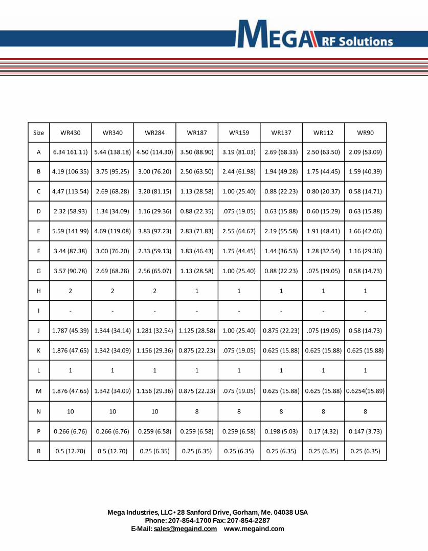
Mega Industries, LLC • 28 Sanford Drive, Gorham, Me. 04038 USA
Phone: 207-854-1700 Fax: 207-854-2287 E-Mail: [email protected] www.megaind.com
Size WR430 WR340 WR284 WR187 WR159 WR137 WR112 WR90
A 6.34 161.11) 5.44 (138.18) 4.50 (114.30) 3.50 (88.90) 3.19 (81.03) 2.69 (68.33) 2.50 (63.50) 2.09 (53.09)
B 4.19 (106.35) 3.75 (95.25) 3.00 (76.20) 2.50 (63.50) 2.44 (61.98) 1.94 (49.28) 1.75 (44.45) 1.59 (40.39)
C 4.47 (113.54) 2.69 (68.28) 3.20 (81.15) 1.13 (28.58) 1.00 (25.40) 0.88 (22.23) 0.80 (20.37) 0.58 (14.71)
D 2.32 (58.93) 1.34 (34.09) 1.16 (29.36) 0.88 (22.35) .075 (19.05) 0.63 (15.88) 0.60 (15.29) 0.63 (15.88)
E 5.59 (141.99) 4.69 (119.08) 3.83 (97.23) 2.83 (71.83) 2.55 (64.67) 2.19 (55.58) 1.91 (48.41) 1.66 (42.06)
F 3.44 (87.38) 3.00 (76.20) 2.33 (59.13) 1.83 (46.43) 1.75 (44.45) 1.44 (36.53) 1.28 (32.54) 1.16 (29.36)
G 3.57 (90.78) 2.69 (68.28) 2.56 (65.07) 1.13 (28.58) 1.00 (25.40) 0.88 (22.23) .075 (19.05) 0.58 (14.73)
H 2 2 2 1 1 1 1 1
I ‐ ‐ ‐ ‐ ‐ ‐ ‐ ‐
J 1.787 (45.39) 1.344 (34.14) 1.281 (32.54) 1.125 (28.58) 1.00 (25.40) 0.875 (22.23) .075 (19.05) 0.58 (14.73)
K 1.876 (47.65) 1.342 (34.09) 1.156 (29.36) 0.875 (22.23) .075 (19.05) 0.625 (15.88) 0.625 (15.88) 0.625 (15.88)
L 1 1 1 1 1 1 1 1
M 1.876 (47.65) 1.342 (34.09) 1.156 (29.36) 0.875 (22.23) .075 (19.05) 0.625 (15.88) 0.625 (15.88) 0.6254(15.89)
N 10 10 10 8 8 8 8 8
P 0.266 (6.76) 0.266 (6.76) 0.259 (6.58) 0.259 (6.58) 0.259 (6.58) 0.198 (5.03) 0.17 (4.32) 0.147 (3.73)
R 0.5 (12.70) 0.5 (12.70) 0.25 (6.35) 0.25 (6.35) 0.25 (6.35) 0.25 (6.35) 0.25 (6.35) 0.25 (6.35)

Mega Industries, LLC • 28 Sanford Drive, Gorham, Me. 04038 USA Phone: 207‐854‐1700 Fax: 207‐854‐2287
E‐Mail: [email protected] www.megaind.com