design standards - george washington university
TRANSCRIPT
DESIGN STANDARDS for New Construction and Major Renovations
Facilities Resources and Planning
April 2020

_________________________________________________________________________
_________________________________________________________________________ Introduction 1 Binder Cover Letter Revision date: 7/1/14 Document date: 9/22/09
THE GEORGE WASHINGTON UNIVERSITY DESIGN STANDARDS This document provides design standards only, and is not intended for use, in whole or in part, as a specification. Consultants referencing this information must always meet all applicable state and local building codes as well as all barrier free design requirements. Consultants must also refer to the entire set of Design Standards for additional information. Refer questions and comments regarding the content and use of this document to the George Washington University Project Manager.
NOTE TO REVIEWERS
The development of The George Washington University Design Standards will be an ongoing project, with periodic updates. To that end, the Design Standards are subject to revision at any given time as the University develops new standards or revises existing standards. Currently, there are sections that contain preliminary or draft information; work from previous efforts to develop design standards; or simple notes as a starting point. To distinguish such documents, they have the watermark “Draft”. These “Draft” sections are to be used on an interim basis and are open for review and comment to aid in their development.

_________________________________________________________________________
_________________________________________________________________________ Table of Contents 1 Revision date: 4/1/20 Document date: 9/22/09
THE GEORGE WASHINGTON UNIVERSITY DESIGN STANDARDS This document provides design standards only, and is not intended for use, in whole or in part, as a specification. Consultants referencing this information must always meet all applicable state and local building codes as well as all barrier free design requirements. Consultants must also refer to the entire set of Design Standards for additional information. Refer questions and comments regarding the content and use of this document to the George Washington University Project Manager.
TABLE OF CONTENTS INTRODUCTION How to use The George Washington University Design Standards and Design
Standards Supporting Documents
DESIGN STANDARDS SUPPORTING DOCUMENTS A. GW Reference Standards
B. Codes and Regulations
C Permitting
D. Utilities and Engineering Requirements
E. Room Numbering
F. Space Planning Guidelines
G. Acoustic Design Criteria
DESIGN STANDARDS BY BUILDING TYPE A. Academic/Administrative Buildings
B. Laboratory Buildings (Draft)
C. Residence Halls - Dormitory Residence Floors
D. Residence Halls - Apartment Style Residence Floors
E. Residence Halls - Common Spaces
F. Parking Structures

THE GEORGE WASHINGTON UNIVERSITY DESIGN STANDARDS
_________________________________________________________________________ Table of Contents 2 Revision date: 4/1/20 Document date: 9/22/09
DESIGN STANDARDS - SPECIFICATION GUIDELINES Division 00 Procurement and Contracting Requirements Division 1 General Requirements 01 10 00
01 21 00
Summary v1.0
Allowances v1.0
01 22 00
01 23 00
01 25 00
01 25 00a
01 26 00
01 31 00
01 32 00
01 32 33
01 33 00
01 40 00
01 42 00
01 58 00
01 60 00
01 73 00
01 74 19
01 77 00
01 78 23
01 78 39
01 79 00
01 79 50a
01 81 13
01 81 16
01 81 19
01 91 13
Unit Prices v1.0
Alternates v1.0
Substitution Procedures v1.0
Substitution Attachment v1.0
Contract Modification Procedures v1.0
Project Management and Coordination v1.0
Construction Progress Documentation v1.0
Photographic Documentation v1.0
Submittal Procedures v1.0
Quality Requirements
References v1.0
Project Identification
Product Requirements v1.0
Execution v1.0
Construction and Demolition Waste Management
Closeout Procedures v1.0
Operation and Maintenance Data v1.0
Project Record Documents v1.0
Demonstration and Training v1.0
Product Warranties v1.0
Sustainable Design Requirements
VOC Limits
Construction IAQ Management
General Commissioning Requirements

THE GEORGE WASHINGTON UNIVERSITY DESIGN STANDARDS
_________________________________________________________________________ Table of Contents 3 Revision date: 4/1/20 Document date: 9/22/09
Division 2 02 41 19
Existing Conditions Selective Demolition
Division 3 Concrete 03 30 00 Cast-in-Place Concrete
Division 5 Metals 05 52 13 Pipe and Tube Railings
Division 6 Woods, Plastics, and Composites 06 40 23 Interior Architectural Woodwork
06 60 00
06 61 13
Plastic Fabrications
Cultured Marble Fabrications
06 61 16 Solid Surfacing Fabrications
Division 7
Thermal and Moisture Protection
07 33 63 Vegetated Roofing
07 50 00 Roofing
07 92 00 Division 8
Joint Sealants Openings
08 11 13 Hollow Metal Doors and Frames
08 14 16
08 31 13
Flush Wood Doors
Access Doors and Frames
08 40 00
08 51 13
08 71 00
Entrances, Storefronts, and Curtain Walls
Aluminum Windows
Door Hardware
08 71 10 Door Hardware Requirements
08 74 00
08 80 00
Access Control Hardware
Glazing

THE GEORGE WASHINGTON UNIVERSITY DESIGN STANDARDS
_________________________________________________________________________ Table of Contents 4 Revision date: 4/1/20 Document date: 9/22/09
Division 9 Finishes 09 29 00 Gypsum Board
09 30 00 Tiling
09 51 13 Acoustical Panel Ceilings
09 64 20 Dance Flooring System
09 65 00 Resilient Flooring
09 66 13
09 66 23
09 68 00
Portland Cement Terrazzo Flooring
Epoxy Resin Terrazzo Flooring
Carpet
09 77 13 Stretched-Fabric Wall Systems
09 77 23
09 91 23
Fabric-Wrapped Panels
Interior Painting
09 96 56
09 97 35
Epoxy Coating
Dry Erase Coating
Division 10
Specialties
10 11 16 Visual Display Surfaces
10 11 23 Bulletin Boards and Bulletin Board Cabinets
10 13 00
10 14 00
Directories
Signage
10 21 13
10 28 00
10 44 00
Toilet Compartments
Toilet and Bath Accessories
Fire Protection Specialties
10 55 00 Postal Specialties
Division 11
Equipment
11 13 19
11 24 23
11 31 00
11 52 13
Loading Dock Levelers
Window Washing Systems
Appliances
Projection Screens

THE GEORGE WASHINGTON UNIVERSITY DESIGN STANDARDS
_________________________________________________________________________ Table of Contents 5 Revision date: 4/1/20 Document date: 9/22/09
Division 12 Furnishings 12 20 00
12 35 30
12 46 33
12 48 13
12 48 16
12 50 00
12 93 13
12 93 43
Window Treatments
Residential Casework
Waste and Recycling Receptacles
Entrance Floor Mats
Entrance Floor Grilles
Furniture Standards for Academic, Administrative and Common Areas
Bike Racks
Site Seating and Tables
Division 14 Conveying Equipment 14 21 00 Elevators
14 91 82 Trash Chutes
Division 21
Fire Suppression
21 13 00
21 31 13
Division 22
Fire-Suppression Sprinkler Systems
Electric-Drive, Centrifugal Fire Pumps
Plumbing
22 00 00
22 11 19
Plumbing
Domestic Water Piping Specialties
22 11 23
22 36 00
22 42 00
Drain Pump Systems
Rainwater Harvesting Systems
Commercial Plumbing Fixtures
22 47 00 Water Coolers
Division 23 23 00 00
23 09 00
Heating, Ventilation and Air Conditioning (HVAC) Heating, Ventilation and Air Conditioning
Instrumentation and Control for Building Automation and
Metering Systems
23 10 00 Facility Fuel Systems

THE GEORGE WASHINGTON UNIVERSITY DESIGN STANDARDS
_________________________________________________________________________ Table of Contents 6 Revision date: 4/1/20 Document date: 9/22/09
23 25 00 HVAC Water Treatment
Division 26
Electrical
26 00 00
26 09 23
26 29 23
26 50 00
Electrical, General Requirements
Lighting Control Devices
Variable-Frequency Motor Controllers
Lighting
Division 27
Communications
27 00 00 Information Technology
27 42 00 Electronic Digital Signage Systems
27 53 13 Clock Systems
27 53 19 Bi-Directional Amplifier Systems
Division 28 28 00 00
28 31 00
28 31 49
Division 32
Electronic Safety and Security Electronic Safety and Security
Fire Alarm and Detection
Carbon Monoxide Detection Sensors
Exterior Improvements (Landscape Guidelines and Foggy Bottom Streetscape Elements)
Landscape Guidelines
Hardscape
Decorative Metal Fences and Gates
Trash and Litter Receptacles
Signage
Benches
Ramps
Anti-Skateboarding Devices
END OF SECTION

_________________________________________________________________________
_________________________________________________________________________ Introduction 1 How to use the GW Design Standards.doc Revision date: 1/1/18 Document date: 9/22/09
THE GEORGE WASHINGTON UNIVERSITY DESIGN STANDARDS This document provides design standards only, and is not intended for use, in whole or in part, as a specification. Consultants referencing this information must always meet all applicable state and local building codes as well as all barrier free design requirements. Consultants must also refer to the entire set of Design Standards for additional information. Refer questions and comments regarding the content and use of this document to the George Washington University Project Manager.
INTRODUCTION HOW TO USE THE GEORGE WASHINGTON UNIVERSITY DESIGN STANDARDS AND DESIGN STANDARDS SUPPORTING DOCUMENTS
The George Washington University Design Standards establish the requirements for capital projects, including new and renovation projects, for all work at The George Washington University. At the time of writing, the bulk of major, foreseeable capital projects will happen on the Foggy Bottom Campus in the District of Columbia. This is the largest and most complex of the three University campuses, which also include Mount Vernon Campus in the District of Columbia and Virginia Science and Technology Campus in Loudoun County, Virginia. The primary goals of the Design Standards and Design Standards Supporting Documents are as follows:
1. To provide direction to architects, engineers, and University Project Managers to assist them in providing solutions that conform to the University’s aesthetic and functional demands.
2. To the extent possible, to make Designers and University Project Managers aware of relevant resources and requirements that exist outside of this document, but remain relevant to Project requirements. Some such resources are available through The University, while others are State, Local, or Federal resources or requirements.
Designers are required to utilize and conform to these Design Standards and Design Standards Supporting Documents for all facility design work. Designers are further required to comply with all applicable zoning laws, environmental regulations, NFPA requirements, ASHRAE Guidebooks, and OSHA regulations, as well as all relevant Federal, State and Local codes, whether specifically identified herein or not. In the event that applicable codes and regulations are at variance with these Design Standards or Design Standards Supporting Documents, Consultant shall make The George Washington University Project Manager responsible for the Project aware of the discrepancy and comply with the more stringent requirements. The Designer is required to submit any proposed deviations from these Design Standards by completing the ‘Design Standards Deviation/Modification Request Form’ which can be obtained from the Development/Construction Project Manager or the Planning, Development and Construction website - https://facilities.gwu.edu/sites/g/files/zaxdzs2316/f/downloads/Integrated%20Design%20Review%20Process%20-%20Waiver%20Form.pdf. Written approval from GW is required before the Designer may proceed with the proposed change(s). Any questions, comments, or suggestions to improve The George Washington University Design Standards should be submitted to the Director of Facilities Resources and Planning. If there is a conflict between Drawings, Specifications, and GW Design Standards, the

THE GEORGE WASHINGTON UNIVERSITY DESIGN STANDARDS
_________________________________________________________________________ Introduction 2 How to use the GW Design Standards.doc Revision date: 1/1/18 Document date: 9/22/09
issue shall be escalated to University Project Managers for resolution. If there is reference to discontinued products herein, consultant shall select an equal substitution and confirm substitution of discontinued products with Owner prior to specification. As codes, regulations, products, and preferences change, The George Washington University updates the Design Standards on an as-needed basis. Updates to these Design Standards are released biannually in January and July. The Designer is expected to maintain and work from the version of the standards current at commencement of Project design. In addition to this INTRODUCTION, the following sections are included in The George Washington University Design Standards:
• DESIGN STANDARDS SUPPORTING DOCUMENTS These documents provide guidance that is largely procedural in nature, rather than directly related to design aspects for projects. It is geared not only for designers, but also University Project Managers.
• DESIGN STANDARDS BY BUILDING TYPE These documents provide guidance that is applicable to a given building type. They are only to be used in conjunction with the Specification Guidelines.
• DESIGN STANDARDS - SPECIFICATION GUIDELINES, PART ONE This section is to be developed by Construction Project Management.
• DESIGN STANDARDS - SPECIFICATION GUIDELINES, PART TWO These documents provide guidance that has generally been organized to conform to the Construction Specification Institute’s MasterFormat, current edition, containing 50 divisions. They may be used either in conjunction with Building Type standards or alone on small projects where applicable. The information is intended for the Designer’s use and, under no circumstance, shall it be misconstrued to be - nor used as - specifications for Contractor use. It remains the designer’s responsibility to prepare project-specific Contract Drawings and Specifications, which conform to the Design Standards herein, for Contractor use.
As noted above, the development of The George Washington University Design Standards will be an ongoing project, with ongoing updates. To that end, there will likely be documents subject to revision at any given time as the University develops new Standards or revises existing Standards. Currently, there are sections that contain preliminary or draft information; work from previous efforts to develop design standards; or simple notes as a starting point. To distinguish such documents, they have the watermark “Draft”. Draft sections are to be used on an interim basis and are open for review and comment to aid in their development.

THE GEORGE WASHINGTON UNIVERSITY DESIGN STANDARDS
_________________________________________________________________________ Introduction 3 How to use the GW Design Standards.doc Revision date: 1/1/18 Document date: 9/22/09
END OF SECTION

_________________________________________________________________________
_________________________________________________________________________ Design Standards Supporting Documents 1 A. GW Reference Standards Revision date: 4/1/20 Document date: 7/1/11
THE GEORGE WASHINGTON UNIVERSITY DESIGN STANDARDS This document provides design standards only, and is not intended for use, in whole or in part, as a specification. Consultants referencing this information must always meet all applicable state and local building codes as well as all barrier free design requirements. Consultants must also refer to the entire set of Design Standards for additional information. Refer questions and comments regarding the content and use of this document to the George Washington University Project Manager.
DESIGN STANDARDS SUPPORTING DOCUMENTS GW REFERENCE STANDARDS
A. SUMMARY
In addition to the GW Design Standards, consultants must be aware of the most current, applicable versions of reference standards that are specific to the University which further direct construction work. The consultant, with the guidance of GW, shall determine the applicability of these requirements that may govern the work.
B. REFERENCE STANDARDS 1. For internal GW access, documents may be acquired from the group
box.com location: https://gwu.box.com/s/jhmi597e80o89j44g33jayq30hhn41tj.
2. Consultants shall contact GW Project Manager to obtain the following reference standards:
GW-SPECIFIC STANDARDS
Requirement Description Last Known
Revision Date to be confirmed by project team
GW responsible party
FIM Procedures Manual, Version 1.0 https://pdc.gwu.edu/sites/pdc.gwu.edu/files/downloads/FIM%20Procedures%20Manual%20-%20v1%20August%202014.pdf
Definition of project data needs/deliverables (BIM, non-BIM projects) for integration into FM system; BIM project execution plan
August 2014 Property Information Resource Center
Plan Review and Construction Project Guidelines for GW, “FM Global,” prepared by Factory Mutual Insurance Company1
November 20, 2013
Office of Risk Management

THE GEORGE WASHINGTON UNIVERSITY DESIGN STANDARDS
_________________________________________________________________________ Design Standards Supporting Documents 2 A. GW Reference Standards Revision date: 4/1/20 Document date: 7/1/11
GW-SPECIFIC STANDARDS
Requirement Description Last Known
Revision Date to be confirmed by project team
GW responsible party
DIT Equipment Rooms Construction Standards https://gwu.box.com/s/kz1glq3v9tjmhmopbs1kea0m3u2w1vkn
IT Equipment Room February 22, 2013
Division of Information Technology, Communication Engineering Services
Building Standards for IT Services https://gwu.box.com/s/kz1glq3v9tjmhmopbs1kea0m3u2w1vkn
IT/ Telecommunications Services
October 11, 2013 Division of Information Technology, Communication Engineering Services
Technical Standards for Digital Signage https://gwu.box.com/s/8ze81tvmw9h2l7lm0ynqadqcsic3zfz8
Digital Signage March 19, 2020 Division of Information Technology
Facilities Building Automation Reference Architecture
IT Security/BAS July 26, 2016 Division of Information Technology, Security
CFT Security and Access Standards
June 2, 2010 Mary Paradis, GWPD
Contractor Safety http://my.gwu.edu/files/policies/ContractorSafetyFINAL.pdf Contractor Safety Manual
Contractor Environmental Health and Safety Program Environmental health concerns including asbestos, lead-based paint and mold
March 15, 2017 December 13, 2006
Division of Safety and Security Contact: Health and Emergency Management Services [email protected]
AV Classroom Design Guidelines Document Referenced as “AT Standards” herein
Standards for GW Classrooms. Note: See Academic Buildings Standards for additional information and sections that apply
May 1, 2013 Academic Technologies
THE GEORGE WASHINGTON UNIVERSITY DESIGN STANDARDS
_________________________________________________________________________ Design Standards Supporting Documents 3 A. GW Reference Standards Revision date: 4/1/20 Document date: 7/1/11
GW-SPECIFIC STANDARDS
Requirement Description Last Known
Revision Date to be confirmed by project team
GW responsible party
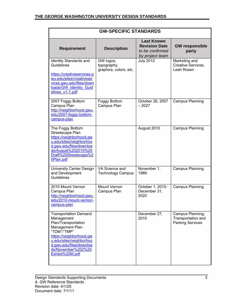
Identity Standards and Guidelines https://creativeservices.gwu.edu/sites/creativeservices.gwu.edu/files/downloads/GW_Identity_Guidelines_v1-1.pdf
GW logos, typography, graphics, colors, etc.
July 2012 Marketing and Creative Services, Leah Rosen
2007 Foggy Bottom Campus Plan http://neighborhood.gwu.edu/2007-foggy-bottom-campus-plan
Foggy Bottom Campus Plan
October 26, 2007 – 2027
Campus Planning
The Foggy Bottom Streetscape Plan https://neighborhood.gwu.edu/sites/neighborhood.gwu.edu/files/downloads/August%202010%20Draft%20Streetscape%20Plan.pdf
August 2010
Campus Planning
University Center Design and Development Guidelines
VA Science and Technology Campus
November 1, 1989
Campus Planning
2010 Mount Vernon Campus Plan http://neighborhood.gwu.edu/2010-mount-vernon-campus-plan
Mount Vernon Campus Plan
October 1, 2010- December 31, 2020
Campus Planning
Transportation Demand Management Plan/Transportation Management Plan “TDM”/”TMP” https://neighborhood.gwu.edu/sites/neighborhood.gwu.edu/files/downloads/November%202%20Exhibit%20M.pdf
December 27, 2010
Campus Planning; Transportation and Parking Services

THE GEORGE WASHINGTON UNIVERSITY DESIGN STANDARDS
_________________________________________________________________________ Design Standards Supporting Documents 4 A. GW Reference Standards Revision date: 4/1/20 Document date: 7/1/11
EXTERNAL/INDUSTRY STANDARDS & GUIDELINES
Requirement Description Last Known
Revision Date to be confirmed by project team
GW responsible party
DC Department of Energy & Environment, Building Energy Performance Standards (BEPS) https://doee.dc.gov/service/building-energy-performance-standards
District building energy performance standards
Utilities and Engineering
DC Historic Preservation Office, Design Guidelines http://planning.dc.gov/page/design-guidelines
Foggy Bottom Campus guidelines to maintain, preserve, and enhance the architectural character of historic structures
Campus Planning
DC Historic Preservation Office, George Washington/ West End Historic District Design Guidelines http://planning.dc.gov/sites/default/files/dc/sites/op/publication/attachments/GW%20Weset%20End%20Design%20Guidelines_0.pdf
Foggy Bottom Campus guidelines to ensure that changes in the historic district align with its historic environment; establish best practices for alterations, additions, and new construction
Campus Planning
BICSI Telecommunications Distribution Methods Manual
Voice/Data/Telecommunications Network Cabling and Infrastructure
Office of Technology Operations and Engineering/ Division of Information Technology
Sustainable Landscape Guidelines https://sustainability.gwu.edu/sites/g/files/zaxdzs2491/f/image/GW%20Sustainable%20Landscape%20Guidelines%20July%202017.compressed.pdf
Landscape design and plant selection, landscape maintenance/ landscape management, ecosystems enhancement strategies
Office of Sustainability/ Sustainable Landscapes Design Group (College of Professional Studies)

THE GEORGE WASHINGTON UNIVERSITY DESIGN STANDARDS
_________________________________________________________________________ Design Standards Supporting Documents 5 A. GW Reference Standards Revision date: 4/1/20 Document date: 7/1/11
EXTERNAL/INDUSTRY STANDARDS & GUIDELINES
Requirement Description Last Known
Revision Date to be confirmed by project team
GW responsible party
LATIS/Landscape Architecture Technical Information Series - Planting Soils for Landscape Architectural Projects (American Society of Landscape Architects)
2013 Adele Ashkar College of Professional Studies, Landscape Design
3. Plan Review and Construction Project Guidelines for GW, “FM Global,”
prepared by Factory Mutual Insurance Company: a. GW’s insurance contract with FM requires that facility designs meet
FM Research guidelines and, when possible, use FM Research-approved products. Contractors/PMs shall submit plans to the Factory Mutual Global Plan Review Department and receive written acceptance prior to starting work. Submittals shall be sent to: [email protected]
b. FM Global generally reviews plans for: • Structural (Roof, Damage-limiting construction, Fire Wall) • Roof Covering • Green Roof Systems • Site plans for new buildings or additions • Architectural drawings • Sprinkler drawings • Alarm system layout and wiring • Special protection systems (CO2, Halon, Dry Chemical) • Fuel fired equipment (Boilers, Ovens, Furnaces) • Process equipment • Electrical power distribution
END OF SECTION

_________________________________________________________________________
_________________________________________________________________________ Design Standards Supporting Documents 1 B. Codes and Regulations Revision date: 1/1/18 Document date: 9/22/09
THE GEORGE WASHINGTON UNIVERSITY DESIGN STANDARDS This document provides design standards only, and is not intended for use, in whole or in part, as a specification. Consultants referencing this information must always meet all applicable state and local building codes as well as all barrier free design requirements. Consultants must also refer to the entire set of Design Standards for additional information. Refer questions and comments regarding the content and use of this document to the George Washington University Project Manager.
DESIGN STANDARDS SUPPORTING DOCUMENTS CODES AND REGULATIONS
A. SUMMARY
In addition to these Design Standards, consultants must be aware of the most current, applicable versions of the codes and regulations, including those noted in this section, which further direct construction work at The George Washington University. The consultant bears the full responsibility of determining the applicability of these and any other codes that may govern the work.
B. CODES, ACTS, STANDARDS AND OTHER REGULATIONS 1. Federal Regulations and Authorities:
a. Americans with Disabilities Act (ADA) i. Consultant shall ensure that the facility design complies with
2010 ADA Standards for Accessible Design effective March 15, 2012 (http://www.ada.gov/2010ADAstandards_index.htm).
b. U.S. Commission of Fine Arts (CFA) (www.cfa.gov) i. Constructing public buildings in certain areas of the National
Capital require review under the Shipstead-Luce Act. This applies to the Foggy Bottom campus only.
GW Buildings Requiring CFA Review • 1900 F St. - Thurston • 2208 F St. • 1918 F St. – Alumni House • 514 19th St. - Mitchell • 1925 F St. – President’s House
• 2031 F St. - JJ • 520 22nd St. • 2033-2037 F St. • 522 22nd St. • 2101 F St. • 524 22nd St. • 2109 F St. • 526 22nd St. • 2115 F St. - Guthridge • 1957 E St. • 2121 F St. • 1959 E St. • 2123 F St. • 2021 F St. - Potomac House • 2138 F St. • 2025 F St. - Support Building • 2140 F St. • 2100 F St. - Dakota • 2142 F St. • 2119 F St. • 2144 F St. • 2141 F St. – Sq. 80 Res. Hall

THE GEORGE WASHINGTON UNIVERSITY DESIGN STANDARDS
_________________________________________________________________________ Design Standards Supporting Documents 2 B. Codes and Regulations Revision date: 1/1/18 Document date: 9/22/09
• 2145 F St. • 2201 Virginia Avenue • 2148 F St. • 600 22nd St. - Smith Ctr. • 2150 F St. • 607 23rd St. - Townhouse Row • 2156 F St. • 616 23rd St. - Ivory Tower • 2206 F St.
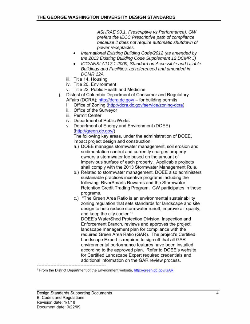
c. National Register of Historic Places - National Park Service, U.S. Department of the Interior (http://www.nps.gov/history/nr/). The National Register of Historic Places, a program of the National Park Service, serves to preserve, protect, and share cultural heritage resources across the nation in partnership with states, local government, and nonprofit organizations. GW’s Foggy Bottom Campus is largely part of the George Washington University/Old West End Historic District, a D.C. Landmark and a listing on the National Register of Historic Places. i. See the map at the end of this section to see the historic district
boundary. ii. See the chart at the end of this section for the list of GW-Owned
historic properties on Foggy Bottom Campus. d. National Capital Planning Commission (www.ncpc.gov)
i. The National Capital Planning Commission (NCPC), through planning, policymaking, and plan review, defines and protects the federal government’s interest in the development of the National Capital Region.
e. The United States Clean Air Act (CAA)(http://www.epa.gov/air/caa/) i. The United States Clean Air Act is a federal law to control air
pollution on a national level. Under this law, the Environmental Protection Agency (EPA) is required to develop and enforce regulations to protect the general public from exposure to materials deemed harmful to human health.
ii. Title V of the Clean Air Act requires each state to develop a comprehensive operating permit program for major industrial sources of air pollution such as burning fossil fuels. The Title V Operating Permit Program requires businesses to monitor, report, and certify compliance with the conditions of the permit.
iii. Title VI of the Clean Air Act regulates ozone-depleting substances such as refrigerants CFCs and HCFCs. Owners and operators of air conditioning and refrigerant systems are responsible for compliance with the program.
2. State and Local Codes, Regulations and Authorities:
a. DC Green Building Act of 2006, DC Law 16-234, took effect March 8, 2007 and amendments to it include the Green Building Technical Corrections Temporary Amendment Act of 2011 (DC Law 19-71).
b. DC Clean and Affordable Energy Act of 2008; took effect on private buildings in December 2010. (Note: while this Act does not directly affect design choices, it should further reinforce the need for providing high performance buildings that will benchmark well in the required Energy Star Building portfolio efforts.)

THE GEORGE WASHINGTON UNIVERSITY DESIGN STANDARDS
_________________________________________________________________________ Design Standards Supporting Documents 3 B. Codes and Regulations Revision date: 1/1/18 Document date: 9/22/09
c. NFPA 13 - Standard for the Installation of Sprinkler Systems d. NFPA 14 – Standard for the Installation of Standpipe and Hose
Systems e. NFPA 20 – Standard for the Installation of Stationary Pumps for
Fire Protection f. NFPA 72 – National Fire Alarm Code g. DC Office of Planning/Historic Preservation Review Board (HPRB)
i. External modifications to designated historic buildings must be coordinated with GW’s Office of Campus Planning and submitted to DC HPRB for review. a.) See the chart at the end of this section for the list of GW-Owned
buildings that require historic review. h. DC Office of Planning/Historic Preservation Review Board (HPRB)
i. Window Repair and Replacement for Historic Properties (memo)
ii. Historic Preservation Review Board’s Window Standards (DCMR Title 10A, Chapter 23) may be accessed at www.planning.dc.gov.
i. District of Columbia Municipal Regulations, including but not limited to: i. DCMR Title 11, Zoning ii. DCMR Title 12, Construction Codes
Note: The Building Code in effect at time of writing is as follows: International Code Council’s 2012 I-Codes, as amended by DC Construction Codes Supplement of 2013. The 2013 DC Construction Code is comprised of the following: • International Building Code/ 2012 (as amended by the 2013
DC Building Code Supplement – 12 DCMR A) • International Residential Code/2012 (as amended by the
2013 Residential Code Supplement 12 DCMR B) • National Electrical Code (NFPA 70) 2011 (as amended by
the 2013 Electrical Code Supplement 12 DCMR C) • International Fuel Gas Code/2012 (as amended by the 2013
Fuel Gas Code Supplement 12 DCMR D) • International Mechanical Code/2012 (as amended by the
2013 Mechanical Code Supplement 12 DCMR E) • International Plumbing Code/ 2012 (as amended by the
2013 Plumbing Code Supplement 12 DCMR F) • International Property Maintenance Code/2012 (as
amended by the 2013 Property Maintenance Code Supplement 12 DCMR G)
• International Fire Code/2012 (as amended by the 2013 Fire Code Supplement 12 DCMR H)
• International Energy Conservation Code/2012 (as amended by the 2013 Energy Conservation Code Supplement 12 DCMR I)
a) The International Energy Conservation Code provides alternative paths for compliance (IECC vs.
THE GEORGE WASHINGTON UNIVERSITY DESIGN STANDARDS
_________________________________________________________________________ Design Standards Supporting Documents 4 B. Codes and Regulations Revision date: 1/1/18 Document date: 9/22/09
ASHRAE 90.1, Prescriptive vs Performance). GW prefers the IECC Prescriptive path of compliance because it does not require automatic shutdown of power receptacles.
• International Existing Building Code/2012 (as amended by the 2013 Existing Building Code Supplement 12 DCMR J)
• ICC/ANSI A117.1 2009, Standard on Accessible and Usable Buildings and Facilities, as referenced and amended in DCMR 12A
iii. Title 14, Housing iv. Title 20, Environment v. Title 22, Public Health and Medicine
j. District of Columbia Department of Consumer and Regulatory Affairs (DCRA); http://dcra.dc.gov/ – for building permits i. Office of Zoning (http://dcra.dc.gov/service/zoning-dcra) ii. Office of the Surveyor iii. Permit Center iv. Department of Public Works v. Department of Energy and Environment (DOEE)
(http://green.dc.gov/) The following key areas, under the administration of DOEE, impact project design and construction: a.) DOEE manages stormwater management, soil erosion and
sedimentation control and currently charges property owners a stormwater fee based on the amount of impervious surface of each property. Applicable projects shall comply with the 2013 Stormwater Management Rule.
b.) Related to stormwater management, DOEE also administers sustainable practices incentive programs including the following: RiverSmarts Rewards and the Stormwater Retention Credit Trading Program. GW participates in these programs.
c.) “The Green Area Ratio is an environmental sustainability zoning regulation that sets standards for landscape and site design to help reduce stormwater runoff, improve air quality, and keep the city cooler.”1 DOEE’s WaterShed Protection Division, Inspection and Enforcement Branch, reviews and approves the project landscape management plan for compliance with the required Green Area Ratio (GAR). The project’s Certified Landscape Expert is required to sign off that all GAR environmental performance features have been installed according to the approved plan. Refer to DOEE’s website for Certified Landscape Expert required credentials and additional information on the GAR review process.
---------------------------------------------- 1 From the District Department of the Environment website, http://green.dc.gov/GAR

THE GEORGE WASHINGTON UNIVERSITY DESIGN STANDARDS
_________________________________________________________________________ Design Standards Supporting Documents 5 B. Codes and Regulations Revision date: 1/1/18 Document date: 9/22/09
d.) DOEE oversees requirements for lead abatement as required under the Lead-Hazard Prevention and Elimination Act have been published in the July 26, 2013. http://green.dc.gov/page/understanding-district%E2%80%99s-lead-laws
k. District Department of Transportation (DDOT) (http://ddot.dc.gov/) i. Public Space permits ii. Tree removal (under specific tree size conditions) iii. Traffic/parking
l. Department of Health (DOH) (http://doh.dc.gov/) i. Community Hygiene Administration – for food vendor reviews
m. Building Codes for Loudoun County, Virginia i. Virginia Uniform Statewide Building Code (VUSBC) is based on
the ICC series of codes with state amendments. Effective July 14, 2014, the 2012 VUSBC is in effect and contains the following parts: a.) 2012 Virginia Construction Code (USBC, Part I) b.) 2012 Virginia Rehabilitation Code (USBC, Part II) c.) 2012 Virginia Maintenance Code (USBC, Part III)
ii. The 2012 VUSBC includes the 2012 ICC model codes including but not limited to the following: • 2012 International Building Code with Virginia State Code
Amendments • 2012 International Plumbing Code with Virginia State Code
Amendments • 2012 International Mechanical Code with Virginia State
Code Amendments • 2011 NFPA 70/National Electrical Code with Virginia State
Code Amendments • 2012 International Fuel Gas Code with Virginia State Code
Amendments • 2012 International Energy Conservation Code with Virginia
State Code Amendments • 2012 International Residential Code with Virginia State
Code Amendments • 2012 International Fire Code NFPA 909, NFPA 45, with
Virginia State Code Amendments, FM Global Requirements n. Loudoun County, Additional codes:
i. 2009 American National Standard Accessible & Usable Buildings and Facilities ICC/ANSI A117.1
ii. US. DOJ 2010 Accessibility Standards with Virginia State Code Amendments
o. Loudoun County Department of Building and Development i. Building Permit Review and Issuance – Building, Electrical, Gas,
Plumbing, Fire Suppression, Mechanical, Occupancy, Soils Report, Grading and Zoning
p. Loudoun County Department of Health i. Health Permit for food service facilities

THE GEORGE WASHINGTON UNIVERSITY DESIGN STANDARDS
_________________________________________________________________________ Design Standards Supporting Documents 6 B. Codes and Regulations Revision date: 1/1/18 Document date: 9/22/09
q. Loudoun County Ordinances i. Administration Code (Chapters 202-296) ii. Building and Housing Code ( Chapters 1410-1460) iii. Fire Prevention Code (Chapter 1602) iv. Planning and Zoning Code (Chapters 1220-1254) v. Streets, Utilities and Public Services Code (Chapters 1020-1098) vi. Traffic Code (Chapters 420-488) vii. Zoning Ordinance
r. Virginia Department of Conservation and Recreation (DCR), Chesapeake Bay Local Assistance – Chesapeake Bay Preservation Act: i. The Chesapeake Bay Preservation Act, enacted by the
Commonwealth of Virginia in 1988, requires the 84 Virginia communities which border on the tidal portions of rivers that drain into the Chesapeake Bay (Tidewater jurisdictions) to implement water quality protection measures to improve the declining condition of this resource and its tributaries.
s. The Virginia Stormwater Management Act, the Virginia Stormwater Management Program (VSMP), and the Clean Water Act authorize and regulate stormwater discharges from Municipal Separate Storm Sewer System (MS4s) and construction activities. VA Science and Technology Campus must adhere to VSMP regulations including the following: i. Stormwater discharges from construction activities require a General
Permit for Discharges of Stormwater from Construction Activities (VAR10) and are governed by the following regulations: a.) Virginia Stormwater Management Act b.) Virginia Stormwater Management Program (VSMP) Regulation
(9VAC25-870) c.) General Permit for Discharges of Stormwater from Construction
Activities (9VAC25-880) Contractor shall verify project profile against the Virginia Department of Environmental Quality (DEQ) criteria to confirm project requirements for general permit coverage.
ii. Stormwater Pollution Prevention Plans (SWPPP): The construction general permit requires the construction activity operator to develop and implement a site specific SWPPP. The SWPPP must be prepared prior to submitting a registration statement for permit coverage to the VSMP Authority or DEQ.
t. Utilities for approval, as required i. Foggy Bottom and Mount Vernon Campuses:
a.) Water and Sewer: DC Water and Sewer Authority (DCWASA; www.dcwasa.com)
b.) Electricity: Pepco (www.pepco.com) – Pepco must provide a load letter agreeing to the engineer’s calculated loads and that Pepco can serve the project
c.) Natural Gas: Washington Gas Light (WGL; www.washgas.com)
d.) No. 2 Fuel Oil: Griffith Energy Services (http://griffithoil.com)

THE GEORGE WASHINGTON UNIVERSITY DESIGN STANDARDS
_________________________________________________________________________ Design Standards Supporting Documents 7 B. Codes and Regulations Revision date: 1/1/18 Document date: 9/22/09
ii. VA Science and Technology Campus: a.) Water and Sewer: Loudoun Water (www.loudounwater.org) b.) Electricity: Dominion Virginia Power (www.dom.com) c.) Natural Gas: Washington Gas Light (WGL;
www.washgas.com) d.) No. 2 Fuel Oil: Griffith Energy Services (http://griffithoil.com)
C. PERMITTING AND AGENCY APPROVALS The following table outlines protocol for obtaining required permits for renovations, repairs, and new construction, as imposed by various federal, District of Columbia and Virginia governmental regulatory agencies. Full compliance with agency requirements listed below is prerequisite to renovation, repairs, new construction, and the use of and addition to existing buildings and spaces. The university policy is to obtain necessary permits for all work.
Table 1. Regulatory Agency Information
Jurisdiction Agency Departments within agency
Permit Issued
Other Reviews
Federal National Planning Commission
Federal Commission of Fine Arts
Shipstead-Luce Act
Federal District of Columbia
US Environmental Protection Agency (EPA)/ District Department of Energy and Environment (DOEE)
Office of Air and Radiation (US EPA) Air Quality Division (DOEE)
Title V Operating
Permit
Federal District of Columbia
District of Columbia
District Department of Energy and Environment (DOEE)
Lead Abatement
Environmental Impact Form/ Environmental
Impact Screening
Form (EISF), Soil Erosion/ Stormwater
Management, Lead
Abatement

THE GEORGE WASHINGTON UNIVERSITY DESIGN STANDARDS
_________________________________________________________________________ Design Standards Supporting Documents 8 B. Codes and Regulations Revision date: 1/1/18 Document date: 9/22/09
Jurisdiction Agency Departments within agency
Permit Issued
Other Reviews
District of Columbia
District Department of Energy and Environment (DOEE)
Lead Abatement
Environmental Impact Form/ Environmental
Impact Screening
Form (EISF), Soil Erosion/ Stormwater
Management, Lead
Abatement
District of Columbia
District Department of Energy and Environment (DOEE)/ Office of Zoning
Watershed Protection Division, Inspection and Enforcement Branch
Green Area Ratio (GAR) Compliance
District of Columbia
District Department of Energy and Environment (DOEE)/ Office of Zoning
2013 Stormwater
Management Rule
District of Columbia
Department of Consumer & Regulatory Affairs
Green Building Division
District of Columbia
Department of Consumer & Regulatory Affairs
Zoning Building Surveyor Permit Center Public Works Department of Environment
District of Columbia
District Department of Transportation
Public Space Traffic/Parking, Tree Removal
District of Columbia
Office of Planning Historic Preservation Office
Historic Preservation Review Board
Historic Buildings
District of Columbia
Department of Health
Food vendors

THE GEORGE WASHINGTON UNIVERSITY DESIGN STANDARDS
_________________________________________________________________________ Design Standards Supporting Documents 9 B. Codes and Regulations Revision date: 1/1/18 Document date: 9/22/09
Jurisdiction Agency Departments within agency
Permit Issued
Other Reviews
District of Columbia
DC Water & Sewer Authority (WASA)
Utilities approval
Impact of project on
water system - sanitary sewer
and storm sewer,
ground water District of Columbia
Pepco Utilities approval
State of Virginia
Virginia Department of Environmental Quality
Stormwater Management
General Construction
Permit
Loudoun County
Loudoun County Department of Building & Development
Building Electrical
Gas Plumbing
Fire Suppression Mechanical Occupancy Soils Report
Grading Zoning
Loudoun County
Loudoun County Department of Health
Health Health- Food Services Facilities
Loudoun County
Loudoun Water Utilities approval
Loudoun County
Dominion Virginia Power
Utilities approval
Loudoun County
Washington Gas Light
Utilities approval

H S T N W21ST ST NW
G S T N W
23RDST
NW
F S T N W
I S T NW I S T NW
E S T NW
19TH ST NW
PEN NSY LV ANI A A VE N W
23RDST
NW
21ST ST NW
I S T NW
22NDST
NW
20TH ST NW
E S T NW
E S T E X P Y N W
22ND ST NW
PEN NSY LV ANI A A VE N W
Historic District Boundary
Buildings
0 200 400Feet´
Government of the District of Columbia
Office of Planning ~ November 7, 2014
George Washington University/ Old West End Historic District
This map was created for planning purposesfrom a variety of sources. It is neither asurvey nor a legal document. Informationprovided by other agencies should beverified with them where appropriate.
OPID0
0256
01
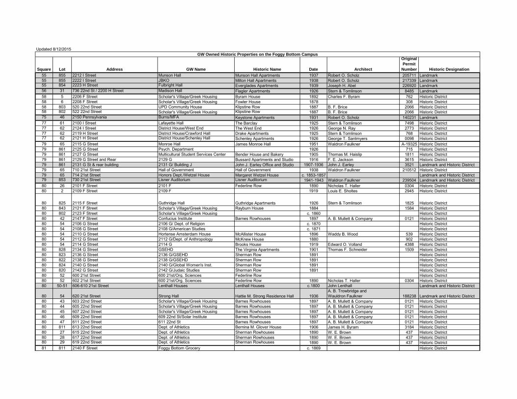
Updated 8/12/2015
Square Lot Address GW Name Historic Name Date Architect
Original Permit
Number Historic Designation55 855 2212 I Street Munson Hall Munson Hall Apartments 1937 Robert O. Scholz 205711 Landmark55 855 2222 I Street JBKO Milton Hall Apartments 1938 Robert O. Scholz 217339 Landmark55 854 2223 H Street Fulbright Hall Everglades Apartments 1939 Joseph H. Abel 226920 Landmark56 31 736 22nd St / 2200 H Street Madison Hall Flagler Apartments 1926 Stern & Tomlinson 8485 Landmark58 5 2206 F Street Scholar's Village/Greek Housing Byram House 1892 Charles F. Byram 762 Historic District58 6 2208 F Street Scholar's Village/Greek Housing Fowler House 1878 308 Historic District58 803 520 22nd Street UPD Community House Klipstine Row 1887 B. F. Brice 2066 Historic District58 802 522 22nd Street Scholar's Village/Greek Housing Klipstine Row 1887 B. F. Brice 2066 Historic District75 46 2150 Pennsylvania Burns/MFA Keystone Apartments 1931 Robert O. Scholz 140231 Landmark77 61 2100 I Street Lafayette Hall The Barclay 1925 Stern & Tomlinson 7498 Historic District77 62 2124 I Street District House/West End The West End 1926 George N. Ray 2773 Historic District77 62 2119 H Street District House/Crawford Hall Drake Apartments 1925 Stern & Tomlinson 768 Historic District77 62 2121 H Street District House/Schenley Hall Schenley Apartments 1926 George T. Santmyers 0098 Historic District79 65 2115 G Street Monroe Hall James Monroe Hall 1951 Waldron Faulkner A-19325 Historic District79 861 2125 G Street Psych. Department 1926 715 Historic District79 861 2127 G Street Multicultural Student Services Center Bender House and Bakery 1905 Thomas M. Haislip 1811 Historic District79 861 2129 G Street and Rear 2129 G Bussard Apartments and Studio 1916 F. E. Jackson 3615 Historic District79 861 2131 G St & rear building 2131 G/ Building J John J. Earley Office and Studio 1907-1936 John J. Earley 3521 Landmark and Historic District79 65 710 21st Street Hall of Government Hall of Government 1938 Waldron Faulkner 210512 Historic District79 65 714 21st Street Honors Dept./Wetzel House Margaret Wetzel House c. 1853-1857 Landmark and Historic District79 853 730 21st Street Lisner Auditorium Lisner Auditorium 1941-1943 Waldron Faulkner 239504 Landmark and Historic District80 26 2101 F Street 2101 F Federline Row 1890 Nicholas T. Haller 0304 Historic District80 2 2109 F Street 2109 F 1919 Louis E. Sholtes 2945 Historic District
80 825 2115 F Street Guthridge Hall Guthridge Apartments 1926 Stern & Tomlinson 1825 Historic District80 843 2121 F Street Scholar's Village/Greek Housing Rayburn House 1884 1584 Historic District80 802 2123 F Street Scholar's Village/Greek Housing c. 1860 Historic District80 42 2147 F Street Confucius Institute Barnes Rowhouses 1897 A. B. Mullett & Company 0121 Historic District80 54 2106 G Street 2106 G/ Dept. of Religion c. 1870 Historic District80 54 2108 G Street 2108 G/American Studies c. 1871 Historic District80 54 2110 G Street Hortense Amsterdam House McAllister House 1896 Waddy B. Wood 539 Historic District80 54 2112 G Street 2112 G/Dept. of Anthropology McKnew House 1880 902 Historic District80 54 2114 G Street 2114 G Brooks House 1919 Edward O. Volland 4388 Historic District80 828 2134 G Street GSEHD The Virginia Apartments 1901 Thomas F. Schneider 1509 Historic District80 823 2136 G Street 2136 G/GSEHD Sherman Row 1891 Historic District80 822 2138 G Street 2138 G/GSEHD Sherman Row 1891 Historic District80 824 2140 G Street 2140 G/Global Women's Inst. Sherman Row 1891 Historic District80 820 2142 G Street 2142 G/Judaic Studies Sherman Row 1891 Historic District80 52 600 21st Street 600 21st/Org. Sciences Federline Row Historic District80 52 602 21st Street 600 21st/Org. Sciences Federline Row 1890 Nicholas T. Haller 0304 Historic District80 50-51 606-610 21st Street Lenthall Houses Lenthall Houses c.1800 John Lenthall Landmark and Historic District
80 54 620 21st Street Strong Hall Hattie M. Strong Residence Hall 1936A. B. Trowbridge andWauldron Faulkner 188238 Landmark and Historic District
80 43 603 22nd Street Scholar's Village/Greek Housing Barnes Rowhouses 1897 A. B. Mullett & Company 0121 Historic District80 44 605 22nd Street Scholar's Village/Greek Housing Barnes Rowhouses 1897 A. B. Mullett & Company 0121 Historic District80 45 607 22nd Street Scholar's Village/Greek Housing Barnes Rowhouses 1897 A. B. Mullett & Company 0121 Historic District80 46 609 22nd Street 609 22nd St/Solar Institute Barnes Rowhouses 1897 A. B. Mullett & Company 0121 Historic District80 47 611 22nd Street 611 22nd St Barnes Rowhouses 1897 A. B. Mullett & Company 0121 Historic District80 811 613 22nd Street Dept. of Athletics Bernina M. Glover House 1906 James H. Byram 3184 Historic District80 27 615 22nd Street Dept. of Athletics Sherman Rowhouses 1890 W. E. Brown 437 Historic District80 28 617 22nd Street Dept. of Athletics Sherman Rowhouses 1890 W. E. Brown 437 Historic District80 29 619 22nd Street Dept. of Athletics Sherman Rowhouses 1890 W. E. Brown 437 Historic District81 811 2140 F Street Foggy Bottom Grocery c. 1869 Historic District
GW Owned Historic Properties on the Foggy Bottom Campus

81 60 2142 F Street Non-GW Affordable Housing Fristoe and Simpson Houses 1890 George S. Cooper 879 Historic District81 59 2144 F Street 2144 F Fristoe and Simpson Houses 1890 George S. Cooper 879 Historic District81 75 2146 F Street Non-GW Affordable Housing 1897 Albert L. Harris 369 Historic District81 81 2150 F Street Non-GW Affordable Housing Pfeil Houses 1909 John C. Deichmann 869 Historic District
101 58
2004, 2006, 2008, 2018, 2022, 2024, 2026, 2030, 2032, 2034, and 2040 I Street, 823 20th St, 825 21st St 2000 Penn Red Lion Row 1831-1896 Landmark and Historic District
101 61 814 21st Street Building XX Union Methodist Church 1846 Historic District101 61 812 21st Street Building YY Union Methodist Church Rectory 1866 Historic District102 46 2003 G Street / 700 20th Street Law School/President’s Office Foster House 1892 George S. Cooper 2003 Landmark and Historic District102 46 2013 G Street Stuart Hall Gilbert Stuart Hall 1936 Edwin Weihle and Robert D. Barnes 192973 Historic District102 46 2023 G Street Lisner Hall Lisner Library 1939 Waldron Faulkner 219655 Historic District102 46 2029 G Street Bell Hall Alexander Graham Bell Hall 1935 Edwin Weihle and Robert D. Barnes 781446 Historic District102 46 2033 G Street / 701 21st Street GW Museum/Woodhull House Woodhull House c. 1855 Landmark and Historic District102 46 2036 H Street Samson Hall Samson Hall 1930 Norris I. Crandall 135044 Historic District102 46 720 20th Street Stockton Hall Stockton Hall 1924 Albert L. Harris and Arthur Heaton 4950 Landmark and Historic District102 46 725 21st Street Corcoran Hall Corcoran Hall 1924 Albert L. Harris and Arthur Heaton 7206 Landmark and Historic District103 41 2031 F Street Building JJ Bloomer Apartments 1905 B. Stanley Simmons 2681 Historic District103 40 2033 F Street 2035 F Street Weaver Rowhouses 1897 Arthur Heaton 336 Historic District103 40 2035 F Street 2035 F Street Weaver Rowhouses 1897 Arthur Heaton 336 Historic District103 40 2037 F Street 2035 F Street Weaver Rowhouses 1897 Arthur Heaton 336 Historic District103 45 2000 G Street Law Learning Clinic/Underwood House Oscar Underwood House c. 1876 Landmark and Historic District103 45 2002 G Street Law Learning Clinic c. 1876 Historic District103 45 2004 G Street Law Learning Clinic c. 1876 Historic District103 43 2036 G Street / 619 21st Street Tonic at Quigley’s Quigley's Pharmacy 1909 F. Woodward and Charles Gregg 4436 Historic District103 1 600 20th Street FSK Hall Francis Scott Key Hotel 1925 George N. Ray 11804 Historic District103 33 605 21st Street Scholar's Village/Greek Housing Weaver Rowhouses 1897 Arthur Heaton 336 Historic District103 34 607 21st Stteet 607 21st Street Weaver Rowhouses 1897 Arthur Heaton 336 Historic District103 35 609 21st Street Davis-Hodgkins House Weaver Rowhouses 1897 Arthur Heaton 336 Historic District121 819 1925 F Street F Street House Steedman-Ray House c. 1849 Landmark and Historic District122 825 1900 F Street Thurston Hall Park Central Apartment Building 1928 Harvey H. Warwick 119865 Historic District122 28 1916-1918 F Street Alumni House Whitney-Lawson Houses c. 1857-1858 Historic District122 28 1922 F Street Old Main St. John's Orphanage 1914 Lynch Luquer 4752 Historic District122 824 514 19th Street Mitchell Hall All State's Hotel 1927 Waddy B. Wood 6769 Historic District171 814, 816 500 17th Street The Corcoran Corcoran Gallery of Art 1897 Ernest Flagg Landmark
GW leased properties owned by a third party. GW maintains them as part of its lease agreementProperties are individually landmarked and are significant on their own meritKey:
_________________________________________________________________________
_________________________________________________________________________ Design Standards Supporting Documents 1 C. Permitting Revision date: 1/1/16 Document date: 9/22/09
THE GEORGE WASHINGTON UNIVERSITY DESIGN STANDARDS This document provides design standards only, and is not intended for use, in whole or in part, as a specification. Consultants referencing this information must always meet all applicable state and local building codes as well as all barrier free design requirements. Consultants must also refer to the entire set of Design Standards for additional information. Refer questions and comments regarding the content and use of this document to the George Washington University Project Manager.
DESIGN STANDARDS SUPPORTING DOCUMENTS PERMITTING1
A. DEPARTMENT OF CONSUMER AND REGULATORY AFFAIRS (DCRA) PERMIT
APPLICATION PROCESS AND REQUIREMENTS
1. Pre-application a. DCMR zoning regulations
i. “Regulations controlling and restricting the height, bulk, number of stories, and size of buildings and other structures, the open spaces around them, the density of the population, and the uses of buildings, structures, and land in the District of Columbia, and for said purposes dividing the District of Columbia into zoning districts.”2
b. Office of the Surveyor documents may need to be submitted with the permit application.
c. New address issuance (if applicable) d. Preliminary Design Review Meeting (PDRM): this meeting will provide
applicants with a preliminary review of their building plans prior to filing. e. Other pre-application meetings with WASA, DDOT and DOH may be
beneficial to eliminate unforeseen obstacles during review of permit applications.
f. Environmental Review i. This review is required to determine whether an Environmental Impact
Statement is necessary. Permit applicants must submit an Environmental Intake Form with the building permit application.
g. Green Building Review: i. Project team designee may meet with District Green Building
Coordinator/DCRA Green Building and Sustainability Coordinator to review the Green Checklist (LEED) and determine how items on checklist will be demonstrated.
ii. Documentation includes: Green Building Act Intake Form h. Green Area Ratio:
i. Project team must plan to integrate landscape features that provide pervious surfaces in the project site design in the early phases of the project in order to meet minimum Green Area Ratio (GAR) coverage requirements.
i. Intake/Completeness Check
1 From the DC Department of Consumer and Regulatory Affairs website, http://dcra.dc.gov/ 2 District of Columbia Municipal Regulations, Title 11, Chapter 1, 1-1.

THE GEORGE WASHINGTON UNIVERSITY DESIGN STANDARDS
_________________________________________________________________________ Design Standards Supporting Documents 2 C. Permitting Revision date: 1/1/16 Document date: 9/22/09
2. Permit Application Submittal a. In addition to submitting hard copy format/paper application, DCRA now
provides the option for filing a building permit application online. http://cpms.dcra.dc.gov/OCPI/PermitApp.aspx
3. Plan Submittal a. ProjectDox is the new online application system that expedites the building
permit application process by allowing electronic submittal of building plans and supporting documentation.
b. Green Area Ratio (GAR) plans for new buildings shall be submitted during the Foundation-to-grade or Civil permit application to allow coordination with stormwater plan review. Submit GAR plans for additions or interior renovations during the Building Permit application.
4. Plan Review 5. Permit Issuance
a. Inspections i. Building inspections: plumbing, electrical, fire and construction
inspections are conducted to assure the building has been constructed in accordance with the codes and approved plans.
b. Certificates of Occupancy (C of O) i. A C of O is required for occupancy of all buildings except single-family
dwellings. Once granted, the certificate must be displayed onsite. ii. Green Area Ratio:
a.) A C of O will not be granted until a signed Landscape Checklist is received by DOEE. A signed Landscape Checklist has been reviewed and approved by the project’s Certified Landscape Expert and the DOEE Inspector and verifies that the project complies with the GAR requirement.

THE GEORGE WASHINGTON UNIVERSITY DESIGN STANDARDS
_________________________________________________________________________ Design Standards Supporting Documents 3 C. Permitting Revision date: 1/1/16 Document date: 9/22/09
B. REQUIRED PERMITS See Table 1. Web links to permits are provided in footnotes. Table 1: Types of work and required permits
Work Type
Zoni
ng3
Sur
vey4
Bui
ldin
g P
erm
it5
Pub
lic S
pace
P
erm
it6
DC
WA
SA
ap
prov
al*
Sup
plem
enta
l P
erm
it
C o
f O7
DO
H a
ppro
val
New construction ● ● ● ● ● (if applicable) ● Renovation of existing building- food venues ● ● (if applicable) ● ●
Major repairs ● (if applicable) ●
Demolition ●
Signage ●
Awnings/Canopies ● ●
Street/Alley closing ● Dumpsters in public space ●
Sidewalks ● ● ●
Streetscape ●
Water or sewer lines ● Excavations (water meters and vaults) ●
A/C & Refrigeration8 ● Plumbing fixture9 ● Electrical systems10 ●
Gas appliances ●
*In addition to obtaining approval, contractor must contact Miss Utility at 1-800-257-7777 at least two working days before digging to avoid damaging gas lines. **This type of work requires a completed Application to Close a Street or Alley.11
3 Summary of overlay districts: http://www.dcoz.dc.gov/info/overlay.shtm 4 Requirement information: http://dcra.dc.gov/service/get-building-plat 5 Permit: http://dcra.dc.gov/service/get-building-permit 6 Permit: http://ddot.dc.gov/DC/DDOT/Services/Permitting+Applications 7 Permit application: http://dcra.dc.gov/service/zoning-certificates-occupancy 8 Permit: http://dcra.dc.gov/sites/default/files/dc/sites/dcra/publication/attachments/ACsupplemental_fillable.pdf 9 Permit: http://dcra.dc.gov/sites/default/files/dc/sites/dcra/publication/attachments/plumbingsupplementalfy2013afillableb%20%281%29.pdf 10 Permit: http://dcra.dc.gov/sites/default/files/dc/sites/dcra/publication/attachments/electricalsupplemental_rev_fillable_ABC.pdf 11 Application: http://dcra.dc.gov/sites/default/files/dc/sites/dcra/publication/attachments/Closure_Application.pdf
THE GEORGE WASHINGTON UNIVERSITY DESIGN STANDARDS
_________________________________________________________________________ Design Standards Supporting Documents 4 C. Permitting Revision date: 1/1/16 Document date: 9/22/09
C. DCRA THIRD PARTY REVIEWS 1. Permit applicants may hire third parties to review drawings and have inspectors
conduct inspections on electrical, plumbing, mechanical, construction, fire protection and elevators. These companies or individuals must be licensed and certified by the District of Columbia. To request third party inspection:
a. Select a certified inspector from the Certified Third Party Inspectors List on DCRA website: http://dcra.dc.gov/page/certified-third-party-inspection-agency-listings
b. Submit a Notification of Intent to Use Third Party Inspection Agency Form http://dcra.dc.gov/sites/default/files/dc/sites/dcra/publication/attachments/thirdparty_fillable_3party_06_15_10.pdf
D. LOUDOUN COUNTY PERMIT REQUIREMENTS
1. Prior to commencement of construction in Loudoun County, permits must be
obtained from the appropriate county agencies and, if applicable, the appropriate agencies of the incorporated towns. Most permits listed below are issued through the Loudoun County Department of Building and Development.
2. Loudoun County requires the following permits for commercial construction: • Building Permit: Three sets of architectural drawings and two copies of the
site plan for new construction or additions • Electrical Permit: Submit one set of plans with completed application.
http://www.loudoun.gov/DocumentCenter/View/97963 • Fire Suppression Permit: Submit three sets of plans with completed
application. http://www.loudoun.gov/DocumentCenter/View/97965
• Gas Permit: Submit one set of plans with completed application. http://www.loudoun.gov/DocumentCenter/View/97966
Grading Permit: If disturbing 5,000 square feet or more • Health Permit: Food Service Facilities and/or property served by private
well/septic. http://www.loudoun.gov/index.aspx?nid=1200
• Mechanical Permit: Submit one set of plans with completed application. http://www.loudoun.gov/DocumentCenter/View/97967
• Occupancy Permit: New construction, additions, and tenant fit-ups • Plumbing Permit: Submit one set of plans with completed application.
http://www.loudoun.gov/DocumentCenter/View/97968 • Soils Report: Two copies of a Type II Geotechnical Report for new
construction • Zoning Permit
http://www.loudoun.gov/index.aspx?NID=1203 3. Separate applications and permits are required for the following: building,
electrical, fire suppression, gas, plumbing and mechanical work. These permits are processed separately from the application and architectural plans submitted

THE GEORGE WASHINGTON UNIVERSITY DESIGN STANDARDS
_________________________________________________________________________ Design Standards Supporting Documents 5 C. Permitting Revision date: 1/1/16 Document date: 9/22/09
for a Building Permit. Contractors must have a valid Virginia State Contractors License and Loudoun County Business License.
4. The Virginia Stormwater Management Act, the Virginia Stormwater Management Program (VSMP), and the Clean Water Act authorize and regulate stormwater discharges from Municipal Separate Storm Sewer System (MS4s). a. Stormwater discharges from construction activities require a General Permit
for Discharges of Stormwater from Construction Activities (VAR10) and are governed by the following regulations: i. Virginia Stormwater Management Act ii. Virginia Stormwater Management Program (VSMP) Regulation (9VAC25-
870) iii. General Permit for Discharges of Stormwater from Construction Activities
(9VAC25-880) Contractor shall verify project profile against the Virginia Department of Environmental Quality (DEQ) criteria to confirm project requirements for general permit coverage.
b. Stormwater Pollution Prevention Plans (SWPPP): The construction general permit requires the construction activity operator to develop and implement a site specific SWPPP. The SWPPP must be prepared prior to submitting a registration statement for permit coverage to the VSMP Authority or DEQ.
END OF SECTION

_________________________________________________________________________
_________________________________________________________________________ Design Standards Supporting Documents 1 D. Utilities & Engineering Requirements Revision date: 1/1/19
Document date: 9/22/09
THE GEORGE WASHINGTON UNIVERSITY DESIGN STANDARDS This document provides design standards only, and is not intended for use, in whole or in part, as a specification. Consultants referencing this information must always meet all applicable state and local building codes as well as all barrier free design requirements. Consultants must also refer to the entire set of Design Standards for additional information. Refer questions and comments regarding the content and use of this document to the George Washington University Project Manager.
DESIGN STANDARDS SUPPORTING DOCUMENTS UTILITIES & ENGINEERING REQUIREMENTS The focus of this document is to summarize the requirements of Utilities & Engineering (U&E), a department of GW Facilities and Campus Development, and is primarily intended for use by Construction Project Teams at The George Washington University. General U&E responsibilities include utilities management and environmental compliance for GW’s facilities. The utilities management responsibilities include ensuring that GW’s 600 utility meters (i.e., electric, gas, and water) are read regularly, utility bills are paid on time, and agreed-upon rates are paid for GW’s utilities. U&E has also implemented energy and water conservation projects in existing buildings to reduce campus energy and water consumption. U&E’s environmental compliance responsibilities include ensuring that GW maintains compliance with State and Federal environmental regulations, which primarily include the Clean Air Act (CAA), Clean Water Act (CWA), Safe Drinking Water Act (SDWA), and Resource Conservation and Recovery Act (RCRA). U&E oversees compliance activities that are regulated by these environmental acts, as described in additional detail below. Assistance from the Construction Project Managers and Project Teams is requested to support the above utilities management and environmental compliance activities. U&E’s current contact is Janine Helwig (202-994-5141, [email protected]), located at the Support Building at 2025 F Street NW on the Foggy Bottom Campus. Questions or comments for U&E may be directed to Ms. Helwig. Utilities
• If GW will be paying the utility bills for a development site during its construction, U&E will establish the temporary or permanent utility accounts when provided with the anticipated date(s) that the construction team needs the utility companies to connect electricity, gas, and water. The following information should be provided: What date will temporary power be needed? What date will temporary power become permanent power? What date will natural gas be needed? What date will water be needed? When will the first delivery of oil be needed?
• If the construction team chooses to contact the utility companies directly, please
emphasize that GW is a non-profit organization that is not required to pay sales and use taxes and that future utility bills should be sent to the following address for payment:

THE GEORGE WASHINGTON UNIVERSITY DESIGN STANDARDS
_________________________________________________________________________ Design Standards Supporting Documents 2 D. Utilities & Engineering Requirements Revision date: 1/1/19
Document date: 9/22/09
The George Washington University 2025 F Street, NW, Suite 200
Washington, DC 20052 Please note that construction-related fees for permits or utility-related services are paid through GW’s Construction Project Manager and not directly through GW’s Accounts Payable office.
• U&E purchases natural gas and electricity for GW on a long-term basis from suppliers other than from the local utility companies; therefore, U&E needs the best engineering estimates of the future natural gas and electric (demand and kWh) loads in a new facility as far in advance as possible from when these utilities are needed, including anticipated seasonal variations. Results of LEED energy models can usually serve this purpose.
• As GW purchases natural gas and electricity on a long-term basis, these contracts
typically have clauses stating that 90-day advanced notice must be given to close an existing gas or electric account, otherwise GW is subject to paying a penalty. U&E can provide this notification if the project team informs U&E of the team’s plans to close an account due to the sale or demolition of a building.
• DC Water meters within GW’s buildings typically have an automated meter reading
(AMR) system that can be read remotely. All new water meters should be configured in this way to allow a radio-signal-sending device to be located near a building’s exterior wall or within a manhole outside. U&E can assist the construction team with acquiring the meter, strainer, and AMR unit from DC Water, as well as scheduling DC Water to program the AMR to begin transmission of meter readings.
• DC Water allows the University to obtain a sewer fee credit for water evaporated
from cooling towers, used for irrigation, and used for humidification, i.e., for purposes that do not return the water to the sewer system. To obtain these credits, meters provided by DC Water must be obtained and installed within each building in appropriate places, using the radio-signal-sending device attached to each meter.
Environmental Requirements – Air
• Fuel-burning equipment is considered to be sources of air pollution and are regulated under GW’s CAA Title V Operating Permit; thus, information on all fuel-burning equipment (gas or oil) must be submitted to both the DC Department of Consumer and Regulatory Affairs (DCRA) and the District Department of Energy and Environment (DOEE) prior to equipment installation. The most common fuel-burning equipment installed at GW include boilers, emergency generators, water heaters, fire pumps, packaged HVAC equipment, and gas clothes dryers. Generally, the construction team obtains the DCRA permits, while U&E is responsible for preparing and submitting air permit applications to DOEE (where applicable, see following bullet). The following information is collected via the “Request for Construction/Operating Air Permit From DOEE” Form that is to be completed by the GW Construction Project Manager and submitted to U&E prior to the construction/installation commencement date:

THE GEORGE WASHINGTON UNIVERSITY DESIGN STANDARDS
_________________________________________________________________________ Design Standards Supporting Documents 3 D. Utilities & Engineering Requirements Revision date: 1/1/19
Document date: 9/22/09
Manufacturer name and model number; Serial number (typically provided upon installation); Maximum firing rate (BTU/hour); Exit gas temperature (F); Exit gas velocity (ft/s) and volume through stack (acfm); Stack inner diameter at exit (ft); Stack height above ground elevation (ft); and Anticipated dates and duration of construction (start and end dates);
• U&E maintains an extensive inventory of all fuel-burning equipment that includes the
above requested information. This information is used to calculate and track air emissions from all fuel-burning equipment, which is reported to DOEE twice a year. For fuel-burning equipment that is larger than 5 million BTUs/hr (MMBTU/hr), as well as for emergency generators of all sizes, the appropriate permit applications to construct/operate this equipment will need to be submitted to DOEE no less than 120 days (four months) prior to the construction/installation commencement date. The “Request for Construction/Operating Air Permit From DOEE” Form can also be used to submit the required information to U&E, and the appropriate DOEE application forms will be completed and submitted by U&E.
• The “Request for Construction/Operating Air Permit From DOEE” form can be requested from U&E to report the above requested information prior to installation. In late 2015 and early 2017, DOEE proposed to implement a permit application fee scheme where each permit application will need to be submitted with its required fee before it will be processed. Fees would vary with the size and type of equipment to be permitted. As of July 2017, the rule requiring these fees has not yet been approved.
• If the construction team purchases fuel to run or test one of the permanent fuel-burning devices (e.g., boilers or emergency generators), U&E requires copies of the fuel specifications and the quantity of fuel delivered for usage tracking to estimate air emissions from fuel-burning equipment. Both the specifications and annual fuel usage quantities are reported to DOEE. Emergency generators are not permitted to use fuel containing more than 15 ppm (0.0015%) sulfur (i.e., ultra-low sulfur diesel fuel) and either a minimum cetane index of 40 or a maximum aromatic content of 35 volume percent. Note that Material Safety Data Sheets (MSDS’s) typically do not provide the sulfur content of the fuel.
o This requirement includes reporting the run-time hours and fuel usage for emergency generators that are on site for temporary purposes, e.g., used at a construction site by a contractor.
• Emergency generators that are permitted under GW’s CAA Title V Operating Permit may not operate more than 500 hours annually. Whenever the generators are operated (with the exception of scheduled automatic weekly exercises), the date and time of operation and fuel quantity used during generator operation must be recorded and provided to U&E.

THE GEORGE WASHINGTON UNIVERSITY DESIGN STANDARDS
_________________________________________________________________________ Design Standards Supporting Documents 4 D. Utilities & Engineering Requirements Revision date: 1/1/19
Document date: 9/22/09
• GW’s CAA Title V Operating Permit requires that visible emission tests are performed by a certified opacity reader for boilers with capacities greater than 5 million BTU per hour. Additionally, combustion adjustments must be performed on boilers with capacities greater than 10 million BTU per hour, although GW annually adjusts the combustion process of boilers with capacities greater than 5 million BTU per hour. All boilers are only permitted to burn natural gas or #2 fuel oil (specifically, only ultra-low sulfur diesel fuel is used throughout all 3 campuses).
• U&E monitors the enforcement of prohibiting engine idling on GW Campuses per the
engine idling requirements of DC Municipal Regulations (DCMR) Title 20 Section 900 and as regulated under GW’s CAA Title V Operating Permit. The engine-idling requirements state that engines may not idle for more than three minutes, unless the engine is needed to operate other equipment such as a cement mixer, or to provide heat when the outside temperature is below 32F. GW Construction Project Managers can assist GW in complying with these requirements by reminding their contractors of these requirements. GW may be fined up to $10,000 per violation.
• GW is required by its CAA Title V Operating Permit to ensure that fugitive dust emissions from any material handling or other industrial-type operation or process is prohibited. U&E monitors the various construction sites on a weekly basis to ensure that there are no fugitive dust emissions.
• U&E manages compliance with a Federal requirement (regulated under the CAA) for
refrigerant management that requires U&E to maintain an inventory of refrigerants used on site. When new equipment containing refrigera nts is brought on site, the quantity and type of refrigerant the equipment contains needs to be reported to U&E. Contractors and GW personnel who handle refrigerants must also be appropriately certified to do so.

THE GEORGE WASHINGTON UNIVERSITY DESIGN STANDARDS
_________________________________________________________________________ Design Standards Supporting Documents 5 D. Utilities & Engineering Requirements Revision date: 1/1/19
Document date: 9/22/09
Environmental Requirements – Fuel Oil Storage • As required by the Spill Prevention, Control, and Countermeasure (SPCC) Rule
regulated under the CWA, U&E maintains a SPCC Plan for each campus that includes an inventory of all fuel storage tanks (including generator day tanks) with capacities greater than 55 gallons, and outlines GW’s oil spill prevention, preparedness, and response to prevent oil discharges. Tank locations, capacities, and spill-control features of new fuel tanks are required upon installation so that U&E can maintain an updated SPCC Plan for each campus. Any modifications made to tanks after installation also need to be reported to U&E so that the SPCC Plans and relevant records can be updated accordingly. Refer to Section 23 10 00 for GW’s standards for Facility Fuel Systems.
• As of July 2014, GW owns and operates a total of 9 underground fuel oil storage tanks (USTs) on the Foggy Bottom Campus and 2 USTs on the Virginia Science & technology Campus. These USTs are regulated by Part 280 under RCRA and DCMR Title 20 Chapters 55-70 and all USTs complied with the appropriate environmental regulations at the time they were originally installed or when they were last upgraded.
o U&E is required to submit a “Notification for Underground Storage Tanks—District of Columbia” registration form to DOEE whenever a new underground fuel tank is installed, modified, or removed/abandoned. U&E typically obtains the required information from the contractor performing the installation, modification, or removal work, and will submit the form to DOEE on behalf of the contractor.
• All of GW’s USTs utilize automatic tank gauging systems (ATGs) for various
functions that include monitoring fuel tank levels and performing in-tank leak detection tests. The ATGs utilized by GW’s USTs are primarily manufactured by Veeder-Root (TLS-300, TLS-300C, or TLS-350 models). GW has also utilized ATGs manufactured by Pneumercator (TMS-2000 and TMS-3000 models). Refer to Section 23 10 00 for GW’s preferences to use ATGs manufactured by Veeder-Root (specifically, TLS-350 model). While most of GW’s existing ATGs are not currently connected to their respective building automation systems or to an integrated fuel management system, utilizing Veeder-Root systems will have advantages over systems by other manufacturers when the University eventually decides to tie all of these units together in the future. An additional advantage of the Veeder-Root systems is that they can be configured to provide continuous statistical leak detection (CSLD), so that in-tank leak detection tests can be performed without interrupting the operation of equipment (i.e., oil-burning boilers and generators).
o U&E is responsible for maintaining and calibrating these ATG systems on an annual basis. ATGs may only be calibrated by personnel who are certified to do so. U&E must be notified when power to an ATG system needs to be disconnected or relocated.
THE GEORGE WASHINGTON UNIVERSITY DESIGN STANDARDS
_________________________________________________________________________ Design Standards Supporting Documents 6 D. Utilities & Engineering Requirements Revision date: 1/1/19
Document date: 9/22/09
• Fill ports/spill buckets, tank manways, and tank sumps should be elevated so that water cannot accumulate inside these tank appurtenances, potentially entering into the tank. Examples of this design can be found at Lisner Hall or Duques Hall.
• GW is required by the SPCC Rule to maintain a log of all oil spills that occur on any of the three campuses. This includes spills that occur on construction sites or those that involve GW contractors. An “Oil Spill Notification Form” can be requested from U&E to report the spill and summarize corrective actions that were implemented to prevent recurrence.
• U&E performs monthly visual inspections on aboveground storage tanks with capacities greater than 55 gallons, and performs weekly inspections on underground storage tank locations and their associated ATG systems.
Environmental Requirements – Stormwater
• Major regulated stormwater projects (as defined within the Stormwater Management
and Soil Erosion and Sediment Control Regulation found in DCMR Title 21, Chapter 5) are required to submit a Stormwater Management Plan (SWMP) to DOEE’s Watershed Protection Division. SWMPs must be signed and sealed by a registered professional engineer who is licensed in the District of Columbia. Additionally, effective December 15, 2014, all SWMP applications must be submitted online via DOEE’s Stormwater Database. The following is the standard process for submitting and approving SWMPs to DOEE:
o The certified as-built SWMP (signed and sealed by Engineer) must be
submitted to GW’s Facility Maintenance Director for signature and agreement to maintain the stormwater device(s). A copy of these drawings MUST be submitted to GW’s U&E for recordkeeping, PRIOR TO submitting to DOEE.
o Once DOEE approves the certified as-built SWMP, they will issue a “Final Approval Notice” to the submitting Engineer. A copy of this Final Approval MUST be submitted to GW’s U&E for recordkeeping.
o Projects that achieve retention volume in excess of regulatory requirements
are eligible to apply for Stormwater Retention Credits (SRCs). Applications for SRCs are also required to be submitted via DOEE’s Stormwater Database. As-built SWMPs are required to apply for SRCs.
o Projects that achieve any retention volume are eligible to for RiverSmart
Rewards (RSR) discounts.
• U&E manages the maintenance of stormwater best management practices (BMPs) such as sand filters, rainwater harvesting systems, and green roofs at multiple buildings on the Foggy Bottom and Mount Vernon Campuses. U&E typically visits each stormwater management or treatment device both during and after its installation. U&E requests that they are notified when the DC inspector is on site for the post-construction inspection of each stormwater BMP.

THE GEORGE WASHINGTON UNIVERSITY DESIGN STANDARDS
_________________________________________________________________________ Design Standards Supporting Documents 7 D. Utilities & Engineering Requirements Revision date: 1/1/19
Document date: 9/22/09
o DOEE inspects stormwater management and treatment devices annually and
recommends maintenance or restoration of the devices as necessary.
o BMPs that receive SRCs and RSR discounts will also be inspected by DOEE every 3 years, which is the duration for which SRCs and RSR discounts are certified.
Environmental Requirements – Backflow Prevention
• U&E is responsible for identifying and surveying cross connections and monitoring
the annual testing of backflow prevention devices as regulated under the SDWA to protect GW’s potable water supply from contamination via such cross connections.
END OF SECTION

_________________________________________________________________________
_________________________________________________________________________ Design Standards Supporting Documents 1 E. Room Numbering Revision date: 7/1/18 Document date: 9/22/09
THE GEORGE WASHINGTON UNIVERSITY DESIGN STANDARDS This document provides design standards only, and is not intended for use, in whole or in part, as a specification. Consultants referencing this information must always meet all applicable state and local building codes as well as all barrier free design requirements. Consultants must also refer to the entire set of Design Standards for additional information. Refer questions and comments regarding the content and use of this document to the George Washington University Project Manager.
DESIGN STANDARDS AND SUPPORTING DOCUMENTS ROOM NUMBERING
A. SUMMARY
This section contains design standards for numbering rooms within a building. The room numbering system will allow better wayfinding within buildings by the University community, facilities maintenance personnel, and emergency personnel. In addition, the Building Automation System (BAS), Fire Alarm Panel, and space management inventory shall be coordinated with the room numbering system. The room numbering system will be used for permanent signage for the building. Room number signage is by Owner, but Consultants shall adhere to these standards for consistency. Refer to Specification Guidelines, section 10 14 00 Signage, for basic information related to the Owner’s standard room signage.
B. ROOM NUMBERING STANDARDS 1. When to Apply
a. The room numbering standards shall be applied to the following project types: i. New buildings ii. Major renovations and additions, including new wings and new floors,
shall have the room numbering system described in the Design Standards.
iii. Minor renovations shall have a room numbering system as required to best fit the revised building configuration.
b. All rooms or spaces in a building shall have a room number assignment including break out rooms, storage rooms, pantries, copy rooms, service rooms, and support spaces such as housekeeping rooms, restrooms, and mechanical rooms.
2. Interpretation of Standards a. In the event of a renovation, the design team is responsible for ensuring that
existing numbers outside the area of the scope of work are not duplicated in the numbering scheme for the area within the scope of work.
b. For renovations and additions involving unusual circumstances or atypical design configurations, the Designer shall propose a room numbering scheme and consult with The University Project Manager and the Manager of the Property Information Resource Center (PIRC) for guidance.
3. Numbering System a. Each room shall have a number to provide a clear, consistent and logical
method to identify rooms by number. i. The room numbering sequence shall start at the main entrance and
progress consecutively in a CLOCKWISE direction.
THE GEORGE WASHINGTON UNIVERSITY DESIGN STANDARDS
_________________________________________________________________________ Design Standards Supporting Documents 2 E. Room Numbering Revision date: 7/1/18 Document date: 9/22/09
ii. In buildings with double-loaded corridors, the room numbering sequence shall also progress consecutively in a clockwise direction. Rooms that are physically close shall be numerically close.
iii. In buildings with perimeter spaces as well as a substantial number of interior spaces (such as systems work stations), perimeter spaces shall be numbered in a clockwise direction as indicated above. Once perimeter spaces are numbered, interior spaces shall be assigned a THREE-DIGIT number designating the floor with an UPPERCASE SUFFIX letter, for example, 100A, 100B, etc. The numbering sequence for interior spaces shall also progress in a clockwise direction.
4. Door numbering shall coordinate with room numbering. 5. Number of Digits
a. Standard room numbers shall use a THREE-DIGIT number, with the first digit always referring to the floor, plus applicable prefixes. Refer to the following examples: i. Basements shall be B101 through B199. B1shall be used for the first
level below ground with “B2”,”B3”, etc, assigned to descending levels within the building.
ii. Street / first floor shall be 100 through 199. iii. Second floor rooms shall be 200 through 299 and so on. iv. Mezzanines shall have the prefix M followed by a three-digit number (i.e.
M101 for 1st Floor Mezzanine, M201 for 2nd Floor Mezzanine, etc.). v. Rooftop spaces such as enclosed mechanical penthouse rooms shall
have the prefix R followed by a three-digit number. 6. Suites
a. For suites of rooms, the numbering of those suites shall have ONE number used for the MAIN room with the INTERIOR rooms using the main number with an UPPERCASE SUFFIX letter. i. For a suite of rooms with an entrance from a main corridor, the entrance
of the suite shall be numbered, with each room within the suite receiving a unique suffix letter. For example, Suite 101 would include rooms 101A, 101B, 101C, etc.
ii. Omit letters “I” and “O” to avoid confusion. iii. For existing building renovation projects where the number of new rooms
created within a space exceeds the suffix letter “Z”, office numbering shall proceed as the following example: 101AA, 101AB, 101AC, etc. Signage, by Owner, shall omit the main suite number and indicate: “AA”, “AB”, “AC”, etc.
7. Buildings with more than one distinct wing a. Where a building has a layout such as a central core and two distinct wings
or pods of spaces, provide a break in numbering that corresponds to the wings. For example, Level One of the East wing may be assigned rooms 100-119, while the West wing may be assigned rooms 120-199. The room numbering sequence within each wing shall progress in a CLOCKWISE direction.

THE GEORGE WASHINGTON UNIVERSITY DESIGN STANDARDS
_________________________________________________________________________ Design Standards Supporting Documents 3 E. Room Numbering Revision date: 7/1/18 Document date: 9/22/09
8. Large Buildings a. Buildings where there may be more than 99 numbered rooms per floor shall
have FOUR-DIGIT room numbers. Consult with GW to confirm this approach is appropriate for the building.
9. Residence Halls a. The overall room numbering of Residence Halls shall follow the standard
clockwise approach described earlier. For bedrooms within a main suite that are accessed from a common living room, such as apartment style housing, each bedroom shall have the main room number plus an UPPERCASE SUFFIX letter. For example, if Room 115 has three separate bedrooms, those rooms shall be numbered 115A, 115B and 115C. This is the same room numbering approach of Suites, noted earlier. Where there are multiple bathrooms located inside of a suite, each bathroom shall also have a THREE-DIGIT number plus letter designation. i. Quad Unit Type Example: In Unit 100, where two students share a
bedroom without a bathroom in the space, the room shall be numbered 100A (GW Housing’s Residential Management System designates the bedspaces 100-1 and 100-2). Where two students share a bedroom with a bathroom within the space, the room shall be numbered 100B (GW Housing’s Residential Management System designates the bedspaces 100-3 and 100-4).
b. Individual bedrooms and bathrooms shall also be physically signed with the uppercase suffix letter/number identifier located on the top side of the door frame.
10. Parking a. A prefix “P” shall be used to identify the parking deck. b. Underground parking shall use “P1” for the first level below ground with
“P2”,”P3”, etc, assigned to descending levels within the structure. c. Surface parking shall use numerical digits assigned to spaces in the
associated parking lot. 11. Corridors
a. Corridors/vestibules, stairs, and unenclosed lounges within corridors shall not be physically signed although they should be numbered on all drawings and identified in space management and Facilities FIXit systems in order to facilitate wayfinding for maintenance and operations.
11. Stairs (S), Corridors/vestibules (C), Elevators (EL), Unenclosed lounges within corridors (L): a. All such spaces shall be identified with a single NUMBER designating the
floor, the LETTER(S) indicated in parentheses above, and the NUMBER of the stair or location found on the drawings. For example: i. Stairs on Level Three would be indicated: 3S1, 3S2, etc. ii. Corridors on Level Two would be indicated: 2C1, 2C2, etc.
Rooms 120-199
Core Rooms 100-119

THE GEORGE WASHINGTON UNIVERSITY DESIGN STANDARDS
_________________________________________________________________________ Design Standards Supporting Documents 4 E. Room Numbering Revision date: 7/1/18 Document date: 9/22/09
iii. An unenclosed lounge open to the first corridor on Level One would be indicated: 1C1L.
12. Restrooms (Men, Women, All Gender), Housekeeping, Mechanical, Electrical, and Telecommunications: a. All such spaces shall be identified with the standard THREE-DIGIT number.
Signage, by Owner, shall include text and Braille indicating the room function or building element.
13. Design Review and Approval a. The Designer shall utilize and conform to the room numbering standards,
described herein, in the project documentation. Room numbering shall be indicated on drawings by the Design Development stage for review by the GW. Each subsequent milestone drawing submission shall also be reviewed for compliance with room numbering standards.
14. Construction Documents a. GW-approved room numbers shall be finalized on Construction Documents.
In particular, the room numbering schedule must be included in Construction Documents. Room numbering shall be updated by the Architect on an on-going basis throughout the construction process to reflect design changes through Final Completion.
b. The final room numbering scheme shall be fully coordinated with fire alarm devices, annunciator panels, and other items prior to building occupancy.
c. The final room numbering scheme shall be approved by GW prior to interior sign fabrication.
C. ROOM NUMBERING PROCESS 1. GW staff shall comply with the following requirements:
a. All new renovation or construction project documents shall be reviewed with
the architect and GW to ensure correct room and suite numbering information.
b. Drawings shall be reviewed against the latest version of the ‘GW Design Standards’ for Room Numbering.
c. Once drawings and room numbering are finalized and disseminated to the project manager as final, a copy of the project drawings shall be sent along with any sign orders, move requests, and DIT requests to the end user for phone, staff placement and other assignments.
d. A copy of final drawings shall be held in the office of Facilities and Campus Development with a copy sent to the DIT Manager of Communication Services.
END OF SECTION

_________________________________________________________________________
_________________________________________________________________________ Design Standards Supporting Documents 1 F. Space Planning Guidelines Revision date: 1/1/20
Document date: 7/1/11
THE GEORGE WASHINGTON UNIVERSITY DESIGN STANDARDS This document provides design standards only, and is not intended for use, in whole or in part, as a specification. Consultants referencing this information must always meet all applicable state and local building codes as well as all barrier free design requirements. Consultants must also refer to the entire set of Design Standards for additional information. Refer questions and comments regarding the content and use of this document to the George Washington University Project Manager.
DESIGN STANDARDS SUPPORTING DOCUMENTS SPACE PLANNING GUIDELINES A. SUMMARY
This section contains general standards for space planning.
B. STANDARDS
Space Allocation Guidelines
The University’s goal in its space allocations is to provide functional but efficient space for the university’s operations while recognizing that space is a scarce resource that must be allocated with the upmost care and maximized to the greatest extent possible in order to meet the mission and strategic objectives of the institution. Office Space Planning - Open Floor Plans The University encourages the implementation of an ‘open plan’ solution for planning future projects as an alternative to the office space allocation guidelines indicated below. In an open plan solution, all staff members are accommodated in open workstations, independent of the number of direct reports. The decision to implement this space planning model shall be based on the individual division/departmental policy and be made under the direction of the project development manager. Open floor plans are desirable as they provide flexibility, create opportunities for teamwork and collaboration, and are highly space efficient. The open floor plan solution shall have conference rooms and team rooms to accommodate meetings and private conversations. Access to these spaces shall be based upon the types of meeting required. For example, some spaces shall be used primarily for executive and senior staff meetings, and open to others when not in use, while the remaining number of team rooms shall be open for use by the entire staff. To achieve optimum benefits from the open plan, the design shall maximize the amount of interior glazing for daylight harvesting. To balance visibility and openness with the need for privacy, film or fritting may be provided to partially obscure glazing, door lites and side lites at these spaces. For acoustical treatment, to achieve a higher degree of speech privacy, doors shall have acoustical seals. Partitions in sound-sensitive locations such as meeting rooms, team rooms, and conference rooms shall meet construction assembly requirements per Design Standards section 09 29 00 - Gypsum Board. Refer to the Acoustic Design Criteria section of Design Standards Supporting Documents for additional information.

THE GEORGE WASHINGTON UNIVERSITY DESIGN STANDARDS
_________________________________________________________________________ Design Standards Supporting Documents 2 F. Space Planning Guidelines Revision date: 1/1/20 Document date: 7/1/11
Space Allocations With respect to office space, in new construction or renovations, space shall be allocated not on the basis of position/title, but instead requirements of an individual’s function/role. Guidelines for this allocation follow here: Staff Office Allocations (implemented as of 6/04): An individual staff person shall be assigned one primary work location. Work at other locations must be conducted on a non-assigned shared hotelling basis. For primary work locations, the determination of whether a private office space or workstation is assigned to a staff member shall be determined based on the number of direct reports under his/her purview. If a position has more than ten (10) direct reports, the position may be allocated a private office. If a position has less than five (5) direct reports, no office may be allocated. If a position has between five and ten (5-10) direct reports, the specific nature of the job, work location of direct reports and other such indicators shall be taken into account in determination of the appropriateness of the allocation of an office. The rationale for the direct reporting relationship being a key indicator in office assignment is to properly utilize shared meeting rooms vs. private offices for private personnel-related meetings and the number of direct reports is a direct driver of the requirement to regularly conduct such confidential meetings. A secondary criteria that may indicate the appropriateness of the allocation of an office for positions with less than the requisite number of direct reports shall be the confidentiality of work product of an individual within his/her work unit. Faculty Office Allocations: Deans, department chairs and regular full-time faculty shall be provided with a private office pursuant to the size guidelines below. Regular part-time faculty shall be provided with a shared workspace with access to a shared phone and computer, and shall also be provided with access to shared office equipment. This space may be a private office or an open workstation. Work space size guidelines (originally established 11/93): Dean’s Office 180-200 sf Chair/Department Head, Director 150 sf Staff/Faculty Office 120 sf Open Workstation (Manager) 36 sf Open Workstation (Staff) 36 sf Secretarial Workstation 36 sf Graduate/Student Workstation 36 sf Hotelling Workstation up to 48 sf Offices shall not include private bathrooms.

THE GEORGE WASHINGTON UNIVERSITY DESIGN STANDARDS
_________________________________________________________________________ Design Standards Supporting Documents 3 F. Space Planning Guidelines Revision date: 1/1/20 Document date: 7/1/11
Where it is not feasible to provide specific square footages, a reasonable range shall be used that manages the University’s overarching goal of providing functional workspace while maximizing the overall utilization of space as a scarce resource. Classrooms For classroom space planning guidelines, refer to Building Type Space Standards, Academic/Administrative and The George Washington University Classroom Design Specifications, March 2010, published by Academic Technologies. All Use Restrooms and Shower/Changing Facilities One all use restroom shall be provided in all new base-building construction and full-building renovation projects. The all use restroom shall be in a location that allows access by the general public. The restroom could be accommodated within an ADA/accessible restroom to promote space efficiency. If the building is one where showers are provided (for example, an athletic or exercise science facility), an all use shower/changing room shall also be provided.
Motherhood Rooms
As a key part of the University’s commitment to supporting breastfeeding families in the GW community, motherhood rooms should be provided in all new base-building construction and major renovation projects - academic and administrative buildings. Motherhood rooms shall not be provided in residence halls. The rooms shall be designed to provide the privacy needed for new mothers. Refer to Building Type Space Standards, Academic/Administrative, for specific requirements.
END OF SECTION

_________________________________________________________________________
_________________________________________________________________________ Design Standards Supporting Documents 1 G. Acoustic Design Criteria Revision date: 4/1/19 Document date: 7/1/11
THE GEORGE WASHINGTON UNIVERSITY DESIGN STANDARDS This document provides design standards only, and is not intended for use, in whole or in part, as a specification. Consultants referencing this information must always meet all applicable state and local building codes as well as all barrier free design requirements. Consultants must also refer to the entire set of Design Standards for additional information. Refer questions and comments regarding the content and use of this document to the George Washington University Project Manager.
DESIGN STANDARDS AND SUPPORTING DOCUMENTS ACOUSTIC DESIGN CRITERIA
A. SUMMARY
This section contains acoustic design criteria for The George Washington University. Refer also to The George Washington University Classroom Design Specifications, published by Academic Technologies, for additional information.
B. GENERAL
1. For sound sensitive spaces such as offices, classrooms and conference rooms,
refer to GW Design Standards, Specification Guidelines, Part Two, 09 29 00 Gypsum Board for partition assembly requirements.
C. REFERENCE STANDARDS 1. ANSI/ASA Standard A12.60 - 2010 American National Standard Acoustical
Performance Criteria, Design Requirements, and Guidelines for Schools, Part 1: Permanent Schools
2. 2011 HVAC Applications ASHRAE Handbook, Chapter 48, Sound and Vibration Control
3. AHRI Standard 885-2008; or local equivalent
D. STANDARDS 1. Acoustical Separation: The basis of measurement for the acoustical
separation between spaces is Sound Transmission Class (STC). The guidelines for minimum recommended STC values, with description of the privacy condition, is the following:
Sound Transmission Class (STC) and Degrees of Privacy Acoustical Separation
Assignment (guideline) Subjective Privacy
STC 35+ Lower Level Support Offices, Entrance Partitions to Offices, Pantry/Copy Rooms
‘Fair’ Speech Privacy Normal voices in adjacent office space audible and intelligible some of the time. Raised voices and speakerphones mostly intelligible.

THE GEORGE WASHINGTON UNIVERSITY DESIGN STANDARDS
_________________________________________________________________________ Design Standards Supporting Documents 2 G. Acoustic Design Criteria Revision date: 4/1/19 Document date: 7/1/11
STC 45 Private Offices, Ground or Lower Floor Water Closets
‘Good’ Degree of Privacy Normal voices in adjacent office space audible but unintelligible most of the time. Raised voices, speakerphones and audiovisual presentations partially intelligible.
STC 50 Classrooms, Teaching and Research Labs, General Conference or Meeting Rooms, Work Rooms, Breakout Rooms, Upper Floor Water Closets
‘Excellent’ Degree of Privacy Normal voices in adjacent spaces barely audible. Raised voices, speakerphones and audiovisual presentations audible but mostly unintelligible.
STC 50 Residential/Bedrooms ‘Excellent’ Degree of Privacy Normal voices in adjacent spaces barely audible. Raised voices, speakerphones and audiovisual presentations audible but mostly unintelligible.
STC 55 Larger Classrooms, Forum/Lecture Hall, Specialty Areas
‘Confidential’ Degree of Privacy Normal voices in adjacent space are not audible. Raised voices, speakerphones and audiovisual presentations are barely audible but not intelligible.
STC 55 – Concrete Block
Mechanical Rooms, Animal Holding and Procedure
Mass of concrete block required to reduce low frequency mechanical noise. Typically desired for hygiene considerations in animal areas.
a. End-user groups may review and verify the required degree of privacy.
Upgrading construction assembly of partitions may need to be considered where speech privacy and acoustical separation are critical issues.
b. Partitions and surrounding details shall achieve the performance addressed above. Refer to GW Design Standards, Specification Guidelines, 09 29 00 Gypsum Board, for partition wall assembly requirements for sound-sensitive spaces.
c. Partitions with significant amounts of glass: If sound transmission is considered an issue for occupants, laminated glazing shall be provided, as budget allows.
d. Project requirements or desires for function and circulation may take precedence over the abovementioned acoustical design guidelines such as glass walls, operable walls and/or door openings. GW shall review proposed design solutions.
2. Doors: Provide acoustical door seals such as automatic door sweeps at thresholds to reduce sound transmission and limit disturbance or distraction in areas where a high degree of speech privacy and acoustic separation from surrounding spaces is needed.

THE GEORGE WASHINGTON UNIVERSITY DESIGN STANDARDS
_________________________________________________________________________ Design Standards Supporting Documents 3 G. Acoustic Design Criteria Revision date: 4/1/19 Document date: 7/1/11
3. Background Noise Levels: The background sound level design guidelines, in terms of Noise Criteria (NC) levels, produced by the normal operation of mechanical, electrical and conveying equipment are as follows:
Space/Description Noise Criteria (NC) Level
Ideal Acceptable Classrooms and Seminar Rooms, Forum Rooms with special listening and presentation functions
30 35
Offices, Conference/Meeting Rooms Typical occupancy; Normal listening functions
35 40
Animal Spaces, Labs without Fume Hoods, Corridors, Support Spaces Circulation and active spaces
40 45
Labs with Fume Hoods Labs with significant air flow and equipment noise
45 50
Adjacent to Mechanical Spaces Within 10 -15 feet of mechanical rooms, specifically under supply and return ducts leaving the rooms/ shafts
Ideally would comply with above levels, however, is dependent on final mechanical system layout and noise control options.
4. Vibration Levels: Base building equipment and piping shall have appropriate vibration isolation. There may be sensitive laboratory and imaging equipment that will require specific and local vibration isolation.
5. Campus/Community Noise Levels: Noise emissions from the building, mainly mechanical equipment (garage supply and exhaust, AHU intakes and exhaust fan discharges, cooling towers, etc.), will be evaluated in terms of typical acceptable levels. A/E or acoustical consultant shall comply with local jurisdiction codes and regulations and community noise control requirements, as well as investigate existing sound levels, to determine project design goals.
END OF SECTION

_________________________________________________________________________
_________________________________________________________________________ Building Type Design Standards 1 A. Academic/Administrative Buildings Revision date: 1/1/20 Document date: 9/22/09
THE GEORGE WASHINGTON UNIVERSITY DESIGN STANDARDS This document provides design standards only, and is not intended for use, in whole or in part, as a specification. Consultants referencing this information must always meet all applicable state and local building codes as well as all barrier free design requirements. Consultants must also refer to the entire set of Design Standards for additional information. Refer questions and comments regarding the content and use of this document to the George Washington University Project Manager.
BUILDING TYPE DESIGN STANDARDS ACADEMIC/ADMINISTRATIVE BUILDINGS
A. SUMMARY
This section contains design standards for academic buildings. Refer to related divisions and sections for additional information.
B. BUILDING SPACE TYPES
Academic building spaces included herein, which are typical of many academic projects at GW, include: • Entry Vestibule • Lobby & Related Spaces • Elevator • Hallways & Corridors • Recycling & Waste Station, Built-In • Classroom, Computer Lab, Lecture Hall • Office • Office Suite Reception Area • Break-Out Room, Conference Room, Lounge, Study Room • Public Restroom • Motherhood Room • Pantry • Housekeeping Closet • Mail, Files, Copy, Storage & Similar Spaces • Facilities Services Storage Room • Egress Stair • Electrical, Security, Telephone Closet • Mechanical Room
C. GENERAL ACADEMIC BUILDING STANDARDS
1. The information in this section is provided for general guidance for this building
type. Refer to individual academic building space standards, such as classrooms and offices, for detailed requirements. Refer to all related sections, such as door hardware, lighting, plumbing fixtures, and various finishes for additional information, as well.
2. Doors, frames, and hardware: unless otherwise noted, required by fire ratings, accessibility requirements, or other code reasons: a. Doors: solid, flush wood

THE GEORGE WASHINGTON UNIVERSITY DESIGN STANDARDS
_________________________________________________________________________ Building Type Design Standards 2 A. Academic/Administrative Buildings Revision date: 1/1/20 Document date: 9/22/2009
b. Dimensions i. Interior and exterior steel doors, and interior, flush, solid core, wood
doors: nominal dimensions, 36” wide, 7’-0” high, and 1-3/4” thick, typical c. Frames: steel d. An automatic door opener shall be provided for all accessible restroom doors. e. All doors to group education spaces and all doors opening into a means of
egress must have a vision panel or glass side lite(s). This is required to prevent injury when opening the door and to allow visual access to determine if the space is in use.
f. Door hardware shall comply with the following specification guidelines and GW Reference Standards: i. 08 71 00 Door Hardware ii. 08 71 10 Door Hardware Requirements iii. 08 74 00 Access Control Hardware iv. 28 00 00 Electronic Safety and Security v. GW “CFT Security & Access Standards”
g. See design standards as well as door and door hardware sections for additional information.
3. Windows a. Unless otherwise noted, do not provide insect screens. b. Window treatments shall be limited to one of the following: 1” horizontal
louver blinds or fabric roller shades, either manual or motorized. i. Offices shall have 1” horizontal louver blinds. ii. Tiered classrooms and lecture halls shall have motorized fabric roller
shades. iii. Other spaces shall be as required by the specific project.
4. Finishes a. Painted wood wall paneling and painted wood base are generally undesirable
finishes, as they tend to show wear prematurely. b. Flooring and base:
i. High traffic areas as well as areas that have a direct connection to the outdoors shall have terrazzo or agglomerate tile flooring with terrazzo base.
ii. Unless noted otherwise herein, flooring in other areas may be carpet as appropriate to meet budgetary, acoustical and aesthetic requirements. a.) Carpet shall be carpet tile throughout academic buildings, with the
exception of offices, where broadloom is highly preferred. b.) Where carpet is specified, stained wood or resilient base shall be
provided, as appropriate. 5. Public Entrances
a. All building entries serving the public and directly connected to the outdoors shall contain a permanently installed entryway floor mat system. The system dimensions shall comply with current LEED requirements. See 12 48 16 Entry Floor Grilles for additional requirements. Also see “Entry Vestibule” below for primary entrance requirements.
6. Signage for individual rooms is by owner. Designer to coordinate work with owner-provided signage standards and locations.
7. Bulletin boards, tack strips and other tackable surfaces shall conform to 10 11 23 Bulletin Boards.

THE GEORGE WASHINGTON UNIVERSITY DESIGN STANDARDS
_________________________________________________________________________ Building Type Design Standards 3 A. Academic/Administrative Buildings Revision date: 1/1/20 Document date: 9/22/2009
8. Interior Life Safety
a. Fire Protection: Sprinklers and fire alarms shall comply with all applicable building codes and regulations, including NFPA, as well as FM Global.
b. Refer to Divisions 21 and 28 for additional information. 9. Indoor Air Quality
a. A CO detector shall be provided in mechanical rooms with fuel-burning equipment.
b. CO detector locations in residence halls shall be in accordance with the current DC Construction Code.
10. Thermal Comfort a. HVAC: Refer to space types within this section and Specification Guidelines,
Part 2, Division 23 for requirements. 11. Voice, Data, CATV
a. Wireless network coverage shall exist throughout each building. Coverage shall also extend to outdoor gathering areas immediately adjacent to the building. Typical interior coverage shall be as follows unless otherwise required: i. Data/Video Drop: Typically, 3 dedicated data/video drops per standard
classroom; Academic Technologies to confirm for each project ii. Voice: one direct dial phone per classroom
b. CATV, Voice and Data station outlets shall all be comprised of a 4” by 4” back box, with a 2 x 4 plaster ring, cover plate, and a 1” EMT or equal-sized raceway with pull string that extends back to the main communications horizontal distribution pathway, or to an accessible ceiling that provides a route to the main communications horizontal distribution pathway. Provide junction boxes, as required, to allow cable to be pulled through from the communications closet to the station outlet. Refer to AT Standards for additional information.
12. Power Supply, Lighting, and Controls a. Electrical systems for Academic buildings must be designed to accommodate
future loads with a 25% reserved capacity for switch gear, distribution panels and branch circuit panels. All spare spaces shall readily accept manufacturer’s breakers without modification.
b. Refer to specification guidelines for additional information including standard lamps and lamp colors as well as controls such as occupancy sensors and manual switches.
c. There shall be no motors or other types of equipment located on the side of the transformer that feeds classroom or lecture hall circuits to avoid creating visible and audible disturbances during a presentation. Refer to Academic Technologies “Classroom Design Specifications” for additional information.
d. Consider providing power outlets in furniture as needed to support programmatic needs. A portion of those outlets shall have USB ports
e. Colors and Materials: i. Unless otherwise required, all switches and receptacles shall be white
with stainless steel cover plates. ii. Receptacles on circuits dedicated to computers and specific equipment
shall be orange with stainless steel cover plates.

THE GEORGE WASHINGTON UNIVERSITY DESIGN STANDARDS
_________________________________________________________________________ Building Type Design Standards 4 A. Academic/Administrative Buildings Revision date: 1/1/20 Document date: 9/22/2009
iii. Where switches are co-located and where receptacles are co-located, provide ganged cover plate.
f. Mounting Height: i. Unless otherwise required, locate the following as noted:
a.) Receptacles at 18” AFF b.) Thermostats at 48” AFF c.) Lighting controls at 48” AFF
g. Each floor shall have at least one lockable electrical closet. h. Lighting: Light levels shall comply with Illuminating Engineering Society of
North America (IESNA) current recommendations. Examples of current IESNA lighting levels include: a) offices, classrooms, and laboratories: 30-50 foot candles (depending on specific work tasks) on desks and table tops; b) hallways; 5-8 foot candles; c) stairwells: 5-8 foot candles; d) restrooms: 5-8 foot candles. Refer to the most current issue of the IESNA Lighting Handbook to verify required illumination levels. LEED requirements and guidelines shall also be considered in the lighting design.
i. Lighting Controls (applicable to all academic building spaces unless specifically noted otherwise) i. Public access to lighting controls shall not be provided in public spaces
such as corridors, hallways, and lobbies. ii. Energy-conserving lighting control strategies such as photocells and
occupancy sensors that step down or turn off lighting when it is not needed, such as after-hours or when the space is unoccupied, are required in most spaces throughout academic buildings.
iii. Consultant should be aware that housekeeping is typically performed after-hours in academic buildings. To that end, lighting design shall provide for illumination as required afterhours while still automatically powering down after occupants have vacated the space.
D. SPACE STANDARDS BY TYPE
Entry Vestibule 1. Primary entry vestibules shall be designed as air locks, with two sets of doors:
exterior doors and doors between the entry vestibule and the building lobby. This design provides for increased energy efficiency and improved dirt and particulates control. The vestibule shall also be designed with a permanently installed entryway floor mat system, compliant with current LEED requirements. The floor mat system shall be provided at all building entries serving the public and directly connected to the outdoors. The floor system shall be the full width of the vestibule. See 12 48 16 Entry Floor Grilles for additional requirements.
2. Each primary entrance vestibule shall include one barrier-free entry with assistive door opener(s).
3. Door hardware: self-closing 4. Finishes: to match adjacent lobby
THE GEORGE WASHINGTON UNIVERSITY DESIGN STANDARDS
_________________________________________________________________________ Building Type Design Standards 5 A. Academic/Administrative Buildings Revision date: 1/1/20 Document date: 9/22/2009
Lobby & Related Spaces 1. General: Lobby finishes and fixtures shall typically be upgraded from other
building spaces. While most academic floors and support spaces tend to be somewhat repetitive and heavily programmed, lobbies and related spaces offer an opportunity to introduce and develop a building’s individuality. This section is applicable to primary entrance lobbies on the main floor, including elevator lobbies. However, it may often be appropriate to maintain an aesthetic connection between the public spaces of the main floor and the lobbies and primary corridors on upper floors.
2. Finishes: a. Walls: combination of painted gypsum board and upgraded wood paneling
and trim b. Flooring: terrazzo or terrazzo tile c. Base: terrazzo or stained wood to complement surrounding finishes d. Ceiling: painted gypsum board or painted gypsum board with acoustical
ceiling tile 3. Lighting and Controls
a. Lighting may include specialty fixtures as long as the required lamps are within the standard selection as established in specification guideline section 26 50 00 Lighting.
4. Lobby shall include a bottle filling station with bi-level water cooler. See specification guidelines section 22 47 00, Water Coolers/Bottle Filling Stations, for additional information.
Elevator 1. General
a. See Division 14, Conveying Equipment, for additional elevator requirements. b. Elevators, whether passenger or freight, shall be finished with highly durable
hard surfaces. Carpet shall not be provided in elevator cabs. i. Passenger & Freight Elevator Cab Finishes, Typical
a.) Doors: Stainless steel cladding • Finish: No. 4, satin, directional polish. Apply directional finishes in
long direction of each component. b.) Return panels: Stainless steel cladding; finish: No. 4 satin, directional
polish. Apply directional finishes in long direction of each component. c.) Side and rear panels
• Plastic laminate cladding with stainless steel trim and reveals (Passenger elevator)
• Patterned stainless steel cladding, Rimex 5-SM or approved equal (Freight elevator)
d.) Ceiling/Canopy • Stainless steel finish, with LED downlights
e.) Base: stainless steel; finish: No. 4 satin, directional polish. Apply directional finishes in long direction of component.
f.) Flooring: agglomerate or terrazzo tile or equal hard, highly durable surface to match lobby flooring
g.) Handrails

THE GEORGE WASHINGTON UNIVERSITY DESIGN STANDARDS
_________________________________________________________________________ Building Type Design Standards 6 A. Academic/Administrative Buildings Revision date: 1/1/20 Document date: 9/22/2009
• Stainless steel; round tube 1-1/2 inch diameter, with closed ends • Provide for rear and side walls • Acceptable product and manufacturer: Equivalent to DH 156 by Otis
h.) Provide blanket studs on cab walls and padded blankets for each elevator
Recycling & Waste Station, Built-In 1. General: While GW offers a number of recycling collection variations, a standard
built-in recycling & waste station shall be located in each primary lobby on all floors. They may be also required in additional locations throughout the building, such as primary circulation paths, depending on the size and configuration of the building. Consultant to coordinate locations with Owner. At a minimum, stations shall provide the following: paper recycling; bottle and can recycling; waste disposal; and bulletin board space. Depending on the space and occupant load, it may sometimes be appropriate to provide more than one receptacle of one or more types. Optionally, stations may also include campus newspaper stacks and shelves.
2. Primary lobby locations: To maximize recycling potential, when located in a primary lobby, the recycling and waste station shall be easily seen and physically accessed from the entry. It shall be open to the space, with a bulletin board above.
3. Minimum Requirements: a. Station shall be 6’-0” wide, minimum, with a continuous solid surface counter
top, backsplash, and sidesplashes and with a base cabinet below. Counter shall be 34” AFF. Station shall be surrounded on sides and back with a gypsum board niche, unless alternate material is approved. Provide a soffit at approximately 7’-0” above at station alcove, with two recessed downlights in soffit ceiling to illuminate the recycling/waste area and the bulletin board.
b. A minimum 48” high, full-width, continuous, self-healing, neutral-colored bulletin board shall be located above the countertop on the back wall. Preference is for product/colors that allow for full width and no seams. If seams are necessary, they shall run vertically and sections should be sized equally. See 10 11 23 Bulletin Boards for additional information.
c. Counter shall be approximately 24” deep with 3 labeled apertures for bins below. The apertures shall be centered front to back, and located approximately 24” on center lengthwise, leaving 12” from the center of each end aperture and the adjacent wall. Edges of apertures shall be eased.
d. Each aperture shall have a plaque identifying the collection. The plaque for each aperture shall be 8” long x 2” deep with rounded corners. It shall be mounted with 2” clear from the front of the counter top. Plaque shall be aluminum with block capital letters, approximately 5/8” high.
e. Facing the station, from the left to right, the apertures shall be: i. left: 14” long x 2” deep slot with rounded corners combined with 3” radius
hole with “RECYCLING” plaque (for bottles/cans/paper) ii. center: 5” radius hole with “WASTE” plaque iii. right: 5” radius hole with “WASTE” plaque
f. See 06 40 23 Interior Architectural Woodwork for cabinet construction requirements. Shelves and drawers shall not be provided. Integrated finger

THE GEORGE WASHINGTON UNIVERSITY DESIGN STANDARDS
_________________________________________________________________________ Building Type Design Standards 7 A. Academic/Administrative Buildings Revision date: 1/1/20 Document date: 9/22/2009
pulls shall be provided in the door construction, in lieu of metallic pulls. Additionally, doors and face frame may be wood, rather than laminate, if appropriate for the surrounding space.
g. One full-height door per receptor bin shall be provided. All doors shall be equally-sized. Doors shall typically be wood panel with hardwood edges, an exception to the requirements of 06 40 23 Interior Architectural Woodwork. i. Doors shall have piano hinges. ii. A metal tab pull shall be provided at the top of each cabinet door for ease
of operation. The approved product is Doug Mockett DP3A. h. Recycling/Waste stations shall have doors with integral base for ease of bin
removal. Adjacent flooring material shall continue into cabinet for ease of cleaning.
i. Consultant shall be responsible for specifying and designing millwork to accommodate a readily available heavy duty waste/recycling receptacle model to be used under each aperture in the cabinet. The selected receptacle model and cabinet design should work to maximize the station’s collection capacity. Design shall allow for unencumbered access to pull receptacle straight out from the front for routine maintenance. i. Refer to 12 46 33 Waste and Recycling Receptacles for required trash
and recycling containers. j. Finishes:
i. Ceiling/soffit, wing walls, and the like shall be as required to coordinate with balance of primary adjacent space.
4. Plan View of Counter Top:
RECYCLING
WASTE WASTE
RECYCLING
WASTE WASTE
RECYCLING
WASTE WASTE
RECYCLING
WASTE WASTE
RECYCLING
WASTE WASTE
RECYCLING
WASTE WASTE
RECYCLING
WASTE WASTE
RECYCLING
WASTE WASTE
RECYCLING
WASTE WASTE
RECYCLING
WASTE WASTE
RECYCLING
WASTE WASTE
RECYCLING
WASTE WASTE
RECYCLING
WASTE WASTE
RECYCLING
WASTE WASTE
RECYCLING
WASTE WASTE
RECYCLING
WASTE WASTE
3”

THE GEORGE WASHINGTON UNIVERSITY DESIGN STANDARDS
_________________________________________________________________________ Building Type Design Standards 8 A. Academic/Administrative Buildings Revision date: 1/1/20 Document date: 9/22/2009
Hallways & Corridors 1. General: Buildings will usually require multiple quality grades for the various
corridors and hallways within. The consultant shall use best judgment and coordinate with owner to determine what level is required by specific spaces. In order to provide some measure of guidance, the following comments are offered: a. Corridors and/or hallways directly connected to, and associated with, main
and elevator lobbies often demand an upgraded finish schedule over that noted below in order to achieve aesthetic continuity with the primary lobby.
b. Corridors and/or hallways that serve utility and maintenance spaces, often located in basements, may require a diminished quality level than that listed below. Coordination with the Owner should provide clear direction. Examples of resulting finishes may include painted structure for walls and ceilings, or resilient floor instead of carpet, terrazzo, or tile. i. Walls in areas with high traffic activity that serve utility, maintenance, and
receiving spaces shall have corner guards. ii. Hallways and corridors that service loading dock and receiving areas
shall have 6” high resilient base. c. There will also often be corridors and/or hallways that are “typical” and
deserving of a quality level similar to that of classrooms and offices. These spaces should be confirmed with the Owner and then conform to the standards below. i. Finishes
a.) Walls: painted gypsum board b.) Flooring selection shall generally be carpet, terrazzo or terrazzo tile.
Selection shall reflect consideration of traffic loads, budget, aesthetics, and acoustical requirements. Generally, office suites and hallways serving offices shall be carpet.
c.) Base with carpet: resilient d.) Base with terrazzo or terrazzo tile flooring: terrazzo, 4” high e.) Ceiling: painted gypsum board or acoustical ceiling tile
Classroom, Computer Lab, Lecture Hall 1. General: GW Academic Technologies, in collaboration with RTKL Associates’
Technology Design Group, has developed the following classroom design guidelines and standards “The George Washington University AV Classroom Design Guidelines Document”. This document, referred to as AT standards henceforth, shall be utilized by the consultant in the design of academic facilities. The following categories of classrooms covered in AT standards are noted here:
a. Categories of Classrooms:
i. Under 30 Person Classroom ii. 30 – 50 Student Classroom iii. 50 – 100 Person Lecture Hall iv. Over 100 Person Lecture Hall v. Collaborative Teaching Classroom vi. VTC Classroom

THE GEORGE WASHINGTON UNIVERSITY DESIGN STANDARDS
_________________________________________________________________________ Building Type Design Standards 9 A. Academic/Administrative Buildings Revision date: 1/1/20 Document date: 9/22/2009
It should be noted that many of the tangible differences between the types of classrooms relate to differences in pedagogy/ teaching and learning style and corresponding instructional technology needs. The consultant is responsible for coordinating the requirements of GW Design Standards with the AT Standards and remedying any conflicting requirements directly with the Owner.
2. Programming: a. For general purpose classrooms, the required space allocation per student is
the following: i. Classrooms with traditional, stationary tablet arm chairs: 15 square feet
per student ii. Classrooms with mobile tablet arm chairs: 20 square feet per student
• Seating for classrooms in new construction and major renovation projects is typically this type.
iii. The seating capacity above does not include the instructor presentation area.
3. In large lecture halls, the use of an entry vestibule is desirable to control external noises and light.
4. Finishes: a. Flooring: carpet b. Base: resilient c. Steps in tiered classrooms:
i. Tread: carpet ii. Nosing: rubber
d. Handrails as required by code e. Ceiling: painted gypsum board or acoustical ceiling tile f. Walls: painted gypsum board, custom fabric-covered acoustical panels, or
wood paneling 5. Door and Door Hardware
a. Door: i. Solid, flush wood ii. Minimum 36” wide iii. Vision panel in door and/or adjacent full-height side lite must be provided
to allow people to determine if a room is occupied without opening the door. Glass may be clear, sandblasted, or fritted, as appropriate to accommodate the required vision, while limiting distractions to classroom occupants by activities outside the room.
b. Door hardware: i. General Purpose Classrooms: Passage lock set ii. Departmental/Specialty Classrooms: Classroom lock set iii. Kick plate on push side iv. Closer v. Stop vi. Self-latching
6. Lighting and Controls: a. The notes under general lighting and controls at the beginning of this
document apply to classrooms. However, special care must be given to ensure that occupants are able to appropriately and fully control the lighting for a variety of possible uses to support the unique needs of each category of

THE GEORGE WASHINGTON UNIVERSITY DESIGN STANDARDS
_________________________________________________________________________ Building Type Design Standards 10 A. Academic/Administrative Buildings Revision date: 1/1/20 Document date: 9/22/2009
classroom outlined in the AT standards. The designer shall also refer to the AT standards for lighting guidelines.
b. LEED and Lighting: i. The designer shall achieve a lighting design and lighting strategy that
meets LEED requirements and guidelines, to the greatest extent possible, in the following key areas: light pollution reduction, energy performance, controllability of systems, daylight and views, and interior lighting quality.
c. Light levels (general/ambient, note-taking/task) shall comply with Illuminating Engineering Society of North America (IESNA) current recommendations. Examples of current IESNA lighting levels include: a) offices, classrooms, and laboratories: 30 - 50 foot candles (depending on specific work tasks) on desks and table tops; b) hallways; 5 -8 foot candles; c) stairwells: 5-8 foot candles; d) restrooms: 5-8 foot candles. Refer to the most current issue of the IESNA Lighting Handbook to verify required illumination levels.
d. Refer to Specification Guidelines Divisions 26 50 00 Lighting and 26 09 23 Lighting Control Devices for additional information.
e. General: Lighting and controls for classrooms will also differ based on whether the space is flat-floored or tiered. Unless otherwise required, classrooms for up to fifty students shall be flat-floored, while those with more than fifty occupants shall be tiered. See below for lighting and control feature requirements.
f. All Classrooms i. With the exception of emergency/egress lighting:
• All classroom lighting and manual controls of the lighting shall be initially enabled via an occupancy sensor as required in 26 09 23 Lighting Control Devices. Which specific lights are to illuminate may vary with the specific design, as long as enough light is provided for safe entry and access to manual controls of lighting.
• After the room is vacated, occupancy sensor shall switch all lighting off.
ii. Egress lighting on emergency back-up power supply, whether required by code or not, shall be provided to ensure safe exit from all points in tiered classrooms in the event of a power failure. Egress lighting shall be controlled by either the occupancy sensor and/or manual controls. Such lighting shall typically be one fixture in the overall general lighting layout. The fixture location shall be selected so as to allow for optimum visibility during instruction. It should always be removed from the projection screen. Ideally, it should also be removed from student seating and the primary presentation area.
iii. Locations for controls • Provide manual controls for all lighting convenient to the presentation
area. Do not integrate lighting controls into the A/V system, to prevent complications between the systems.
g. Flat-floor Classrooms: i. General lighting: Fixture styles shall typically be made up of one or a
combination of the following types: • 2’ x 2’ or 2’ x 4’ LED fixtures with 3 or 4 lamps each. Provide
inboard/outboard switching.

THE GEORGE WASHINGTON UNIVERSITY DESIGN STANDARDS
_________________________________________________________________________ Building Type Design Standards 11 A. Academic/Administrative Buildings Revision date: 1/1/20 Document date: 9/22/2009
• 4’ or 8’ long direct/indirect linear pendant fixtures with 3 or 4 lamps each.
• Recessed LED wallwashers ii. Front row lighting in each classroom shall be switched separately from
the general lighting. Front row lighting shall also illuminate the marker board area.
h. Tiered Classrooms i. General lighting shall be dimmable and further controlled by
programmable lighting control system once enabled via occupancy sensor. Fixture styles shall typically be made up of one or a combination of the following types: • 2’ x 2’ or 2’ x 4’ lay-in LED fixtures with 3 or 4 lamps each. Provide
inboard/outboard switching. • 4’ or 8’ long direct/indirect linear LED pendant fixtures with 3 or 4
lamps each. • Recessed LED wallwashers
ii. Front row lighting in each classroom shall be independently switched. Front row lighting shall also illuminate the marker board area.
7. Equipment: a. For specific requirements per classroom type, refer to ‘The George
Washington University AV Design Guidelines Document’ prepared by RTKL Associates Inc. Technology Design Group and GW Academic Technologies.
b. Projection Screens: location and size: per program requirements, AT Standards, and as approved by the Office of Academic Planning and Assessment. See also specification guideline section 11 52 13 Projection Screens.
c. A/V equipment closet flooring shall be VCT; anti-static. 8. Furniture:
a. Desks shall be fixed or movable, dependent upon the program requirements. b. Seating shall be moveable. c. Tablet Arm Chairs:
i. Basis of Design Product and Manufacturer: a.) Node by Steelcase
a) Base: Colors: Platinum or Near Black b) Shell: Colors: Citron, Wasabi, Sterling Dark Solid, Picasso,
Chili, Flash or Jazz Blue c) Frame Paint: Colors: Platinum d) Midback e) Tablet Colors: Finishes: 6249 Platinum Solid (gray laminate
with gray trim) or 2409 Clear Maple (with gray trim)
d. Chairs: i. Basis of Design Product and Manufacturer:
a.) Node by Steelcase a) Base: Colors: Platinum or Near Black. If at a table, 5 point
base with glides or casters

THE GEORGE WASHINGTON UNIVERSITY DESIGN STANDARDS
_________________________________________________________________________ Building Type Design Standards 12 A. Academic/Administrative Buildings Revision date: 1/1/20 Document date: 9/22/2009
b) Shell: Colors: Citron, Wasabi, Sterling Dark Solid, Picasso, Chili, Flash or Jazz Blue
c) Frame Paint: Colors: Platinum d) Midback
e. Stools: i. Basis of Design Product and Manufacturer:
a.) Node by Steelcase a) Base: Colors: Platinum or Near Black b) Shell: Colors: Citron, Wasabi, Sterling Dark Solid, Picasso,
Chili, Flash or Jazz Blue c) Frame Paint: Colors: Platinum d) Midback
f. Student Tables (Mobile, on casters – fixed top): i. Basis of Design Product and Manufacturer:
a.) Verb by Steelcase a) Finishes: 6249 Platinum Solid (gray laminate with gray trim)
or 2409 Clear Maple (with gray trim) g. Student Tables (Mobile, on casters – flip top):
i. Basis of Design Product and Manufacturer: a.) Akira by Coalesse/Steelcase
a) Finishes: 6249 Platinum Solid (gray laminate with gray trim) or 2409 Clear Maple (with gray trim)
h. Teaching Desks (Mobile, on casters): If lectern is provided by Academic Technologies use - i. Basis of Design Product and Manufacturer:
a.) Pocket mobile worksurface by Steelcase a) Finishes: Frame paint and worksurface: Seagull
If classroom has no lectern use - i. Basis of Design Product and Manufacturer:
a.) Verb Instructor Station by Steelcase a) Finishes: To match classroom tables if they exist or gray trim
with grey or maple laminate
9. Specialties: a. Marker Boards
i. Framed in extruded, clear anodized aluminum and conforming to 10 11 00 Visual Display Units.
ii. Provide a continuous tack strip, conforming to 10 11 23 Bulletin Boards, and approximately 2” wide, above all required marker boards.
iii. Provide map hooks attached to each tack strip or to the top of each marker board.
iv. Locations shall be as per the program requirements and approved by the Office of Academic Planning and Assessment.
THE GEORGE WASHINGTON UNIVERSITY DESIGN STANDARDS
_________________________________________________________________________ Building Type Design Standards 13 A. Academic/Administrative Buildings Revision date: 1/1/20 Document date: 9/22/2009
10. Independent temperature controls shall be provided for each classroom, computer lab, and lecture hall.
11. A/V and Technology a. For requirements refer to ‘The George Washington University AV Design
Guidelines Document’ prepared by RTKL Associates Inc. Technology Design Group and GW Academic Technologies.
12. Power and Data a. For requirements refer to ‘The George Washington University AV Design
Guidelines Document’ prepared by RTKL Associates Inc. Technology Design Group and GW Academic Technologies.
Office 1. Finishes
a. Walls: painted gypsum board b. Flooring: carpet c. Base: resilient d. Ceiling: acoustical ceiling tile
2. Door and Door Hardware
a. Door i. Doors: flush wood with a vision panel or full glass lite ii. Vision panel
a.) A vision panel is required in office doors to provide visibility and security for occupants within, balanced with privacy for assigned faculty or staff.
b.) Doors may have a full glass lite in lieu of a vision panel to maximize interior daylighting from perimeter spaces and to support an open plan concept that fosters interaction/collaboration.
c.) Glass shall be 50% obscured by film, fritting or frosting/sandblasting. b. Door hardware to include
i. Office lock set ii. Stop
3. Provide a satin finish cast brass or stainless steel hat and coat hook at 6’-0” AFF on the back of the door, unless lower height is required for barrier-free office. a. Acceptable models:
i. Ives 571 ii. Rockwood 802
4. Lighting and Controls a. General Lighting: 2’ x 2’ or 2’ x 4’, lay-in LED fixtures b. Light control to be 4’-0” AFF and by entry. c. Occupancy sensor to have manual on/auto off capability.
5. Thermostat to be 4’-0” AFF, by the entry and co-located with lighting control. 6. Furniture & Specialties: Owner-provided and installed 7. Owner-Provided Furniture & Furnishings (for design information only)
a. Office furniture, such as desk and bookcases, as required 8. Refer to 12 46 33 Waste and Recycling Receptacles for required trash and
recycling containers.
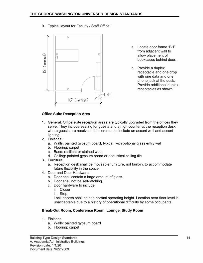
THE GEORGE WASHINGTON UNIVERSITY DESIGN STANDARDS
_________________________________________________________________________ Building Type Design Standards 14 A. Academic/Administrative Buildings Revision date: 1/1/20 Document date: 9/22/2009
9. Typical layout for Faculty / Staff Office:
a. Locate door frame 1’-1” from adjacent wall to allow placement of bookcases behind door.
b. Provide a duplex
receptacle and one drop with one data and one phone jack at the desk. Provide additional duplex receptacles as shown.
Office Suite Reception Area 1. General: Office suite reception areas are typically upgraded from the offices they
serve. They include seating for guests and a high counter at the reception desk where guests are received. It is common to include an accent wall and accent lighting.
2. Finishes: a. Walls: painted gypsum board, typical; with optional glass entry wall b. Flooring: carpet c. Base: resilient or stained wood d. Ceiling: painted gypsum board or acoustical ceiling tile
3. Furniture: a. Reception desk shall be moveable furniture, not built-in, to accommodate
future flexibility in the space. 4. Door and Door Hardware
a. Door shall contain a large amount of glass. b. Door shall not be self-latching. c. Door hardware to include:
i. Closer ii. Stop Lock access shall be at a normal operating height. Location near floor level is unacceptable due to a history of operational difficulty by some occupants.
Break-Out Room, Conference Room, Lounge, Study Room 1. Finishes
a. Walls: painted gypsum board b. Flooring: carpet
THE GEORGE WASHINGTON UNIVERSITY DESIGN STANDARDS
_________________________________________________________________________ Building Type Design Standards 15 A. Academic/Administrative Buildings Revision date: 1/1/20 Document date: 9/22/09
c. Base: resilient d. Ceiling: painted gypsum board or acoustical ceiling tile
2. Lighting: a. General Lighting: ceiling-mounted, recessed or semi-recessed LED fixtures.
Lighting may be direct or direct/indirect, as appropriate. b. Accent lighting by recessed LED fixtures in gypsum board or acoustical
ceiling tile ceiling may also be appropriate in certain applications. 3. Door and Door Hardware
a. Door to be one of the following, typical i. Flush wood with 50% obscured vision panel ii. Door within interior glazing system
b. Door hardware to include: i. Classroom lock set ii. Stop
Public Restroom 1. Finishes:
a. Flooring: unglazed through body porcelain tile b. Walls: glazed tile, floor to ceiling or tile up to 6 feet min. above finished floor.
Top of tile to be fully coordinated with toilet accessories and toilet compartment.
c. Thresholds: marble d. Ceiling: painted gypsum board or acoustical ceiling tile
2. Door and Door Hardware a. An automatic door opener shall be provided for all accessible restroom doors. b. Door: flush wood c. Single-occupant restroom door
i. To be self-latching ii. Hardware to include
a.) Privacy set b.) Stop
d. Multi-occupant restroom door i. Not to be self-latching ii. Hardware to include
a.) Push plate b.) Pull c.) Surface mount closer d.) Kick plate e.) Stop
3. Toilet compartments and urinal screens, where required for multi-occupant restrooms, shall comply with requirements in 10 21 13 Toilet Compartments.
4. Lighting a. Multi-occupant restroom
i. General lighting: 2’ x 2’ or 2’ x 4’ recessed or semi-recessed LED fixtures and/or recessed LED fixtures.
ii. Lighting above lavatories, mirrors, toilets, and urinals: Recessed LED linear slot. Provide lighting above the sinks.

THE GEORGE WASHINGTON UNIVERSITY DESIGN STANDARDS
_________________________________________________________________________ Building Type Design Standards 16 A. Academic/Administrative Buildings Revision date: 1/1/20 Document date: 9/22/09
iii. The light fixture nearest the main restroom door shall be on a 90 minute battery back-up but not on the emergency circuit.
b. Single-occupant restroom, selection as required by space i. 2’ x 2’ or 2’ x 4’ recessed or semi-recessed LED fixtures ii. recessed LED fixtures iii. surface-mounted linear LED fixture above mirror at vanity
5. Plumbing Fixtures: See 22 42 00 Commercial Plumbing Fixtures section for additional requirements on all items. a. Toilets to be wall-hung. b. Urinals to be wall-hung. c. Single-occupant and multiple-occupant restrooms shall have a floor drain. d. Lavatory
i. Where only one lavatory is provided, it shall be wall-hung vitreous china. ii. Where multiple lavatories are provided and adjacent, they shall be
provided as either a continuous, solid surface lavatory top with integral bowls or as undermount, stainless steel lavatories with solid surface counter. Back-/side-splashes shall be solid surface. a.) Provide a continuous, barrier-free solid surface apron at bottom of
counter top, minimum 4” high, recessed 1” minimum from the front edge of counter. Apron shall run along front and any exposed ends of lavatory counter.
b.) Counter shall have one or more 3” radius or 6” x 6” square apertures, with edges eased. Each aperture shall allow convenient waste disposal to a floor-standing waste bin, minimum 13-gallon capacity, below the counter. Dependent on the number of lavatories provided, each sink shall typically have one adjacent counter aperture. Aperture shall be centered between two adjacent sinks. Apertures shall not be located at the end of the counter, beyond the last lavatory. In the case of an odd number of lavatories, this will result in the center lavatory either having no adjacent aperture, or having an adjacent aperture on both the right and the left side.
c.) Provide wall-mounted or under-counter stainless steel brackets to
locate each floor-standing bin in alignment with the aperture above, thus reducing the chance of it being displaced.
d.) Consultant shall coordinate the thickness of the solid surface counter, the height of the apron, and the waste bin(s) provided to allow

THE GEORGE WASHINGTON UNIVERSITY DESIGN STANDARDS
_________________________________________________________________________ Building Type Design Standards 17 A. Academic/Administrative Buildings Revision date: 1/1/20 Document date: 9/22/09
unencumbered access to pull bin straight out from the front for routine maintenance. Typically, counter top shall be 34” above finish floor and ¾” thick. Apron height shall further limit clearance below counter.
e.) Consultant shall ensure that barrier-free access to at least the minimum number of required lavatories is achieved, considering the spacing of the lavatories and the location of the under-counter waste bin(s). Consideration shall include both vertical and horizontal clearances.
e. Lavatory faucet to be touchless and integrate a water-saving auto-sensor. f. Lavatory plumbing pipes shall be insulated to comply with barrier-free
requirements. For aesthetics and ease of maintenance, front panel skirting shall not be provided unless specifically required.
6. Non-lavatory counters, backsplashes and sidesplashes, where provided, shall be solid surface material.
7. Provide a GFCI outlet near the lavatory area. 8. Contractor-Provided Accessories:
a. General: Refer to specification guideline section 10 28 00 Toilet & Bath Accessories for additional information.
b. Provide one framed mirror above each lavatory. Ensure adequate space between the bottom of the mirror and the countertop backsplash to prevent water migration behind the mirror.
c. Provide a single, full-length mirror in multiple occupant restrooms. d. Waste bins: refer to lavatory standards above and within this section for
waste bin style selection and quantity guidance. In general, they should be floor-standing under solid surface counters with lavatories or floor-standing and lidded when used in conjunction with a wall-hung lavatory. i. In a single-occupant restroom, provide one floor-standing lidded, self-
closing stainless steel waste bin, with minimum 13-gallon capacity. ii. In a multi-occupant restroom, provide under-counter, open top stainless
steel waste bins. Selection shall conform to the lavatory requirements in this section and in 10 28 00 Toilet & Bath Accessories.
e. Provide one stainless steel or cast aluminum coat hook per toilet. i. In a single-occupant restroom, mount hook on inside face of entry door. ii. In a multi-occupant restroom, provide one hook on the inside face of each
toilet stall door. iii. Hooks on inward-swinging stall doors shall have a rubber bumper.
f. Provide one folding utility shelf in every toilet compartment, regardless of gender.
g. Sanitary napkin disposal: i. Provide one dedicated or partition-shared disposal per toilet
compartment. Single-occupant restrooms do not require one. ii. Mounting: wall or partition
h. Hand dryer(s); provide count as appropriate. 9. Owner-Provided, Contractor-Installed Accessories:
a. Refer to 10 28 00 Toilet & Bath Accessories for additional information, including required locations and current models for Owner-Provided, Contractor-Installed Accessories as listed below. i. Soap/foam dispensers

THE GEORGE WASHINGTON UNIVERSITY DESIGN STANDARDS
_________________________________________________________________________ Building Type Design Standards 18 A. Academic/Administrative Buildings Revision date: 1/1/20 Document date: 9/22/09
a.) Soap/foam dispensers shall be mounted to the wall above the countertops, between individual mirrors. Countertop-mounted soap dispensers are not acceptable.
ii. Toilet seat cover dispensers iii. Toilet tissue dispensers iv. Paper towel dispensers
Motherhood Room 1. Finishes
a. Walls: painted gypsum board b. Flooring: resilient tile c. Base: resilient d. Ceiling: painted gypsum board or acoustical ceiling tile
2. Door and Door Hardware a. Door: Flush solid wood b. Door hardware to include:
i. Mortise lock with visual indicator thumb- turn a.) Basis of Design, no exceptions: Stanley/Best Access, 40H Visual
Indicator Thumb-Turn option ii. Door stop iii. Satin finish cast brass or stainless steel coat hook on the back of the door
a.) Acceptable Manufacturers and Products: a) Ives 571 b) Rockwood 802
3. Furniture and Furnishings, Owner-Provided (for design information only): a. Comfortable chair b. End table c. Coffee table d. Waste receptacle (Refer to 12 46 33 Waste and Recycling Receptacles for
required container) 4. Contractor-Provided, Contractor-Installed Specialties:
a. Mirror 5. Appliances:
a. MicroFridge (Refer to 11 31 00 Residential Appliances for manufacturer and product information)
6. Toilet and Bath Accessories - Owner-Provided, Contractor-Installed (Refer to 10 28 00 Toilet and Bath Accessories for manufacturer and product requirements): a. Paper towel dispenser b. Soap dispenser
7. Cabinets (above or below sink) shall comply with 06 40 23 Interior Architectural Woodwork. Cabinets shall be lockable.
8. Counters, backsplashes, and sidesplashes shall be finished with plastic laminate. 9. Lighting and Lighting Control:
a. General Lighting: 2’ x 2’ or 2’ x 4’ recessed fixtures b. Lighting control to be mounted 4’-0” AFF by the entry door; co-located with
the thermostat c. Occupancy sensor (PIR, wall-mount) with manual override

THE GEORGE WASHINGTON UNIVERSITY DESIGN STANDARDS
_________________________________________________________________________ Building Type Design Standards 19 A. Academic/Administrative Buildings Revision date: 1/1/20 Document date: 9/22/09
10. Electrical a. Provide (2) duplex convenience outlets near the seating area
11. Plumbing Fixtures a. Sink
12. HVAC
a. Individual room temperature control shall be provided. Thermostat shall be mounted 4’-0” AFF, by the entry; co-located with the lighting control
Pantry 1. Finishes:
a. Walls: painted gypsum board b. Flooring: resilient tile c. Toekick at base cabinets: either plastic laminate or resilient d. Base: resilient e. Ceiling: either painted gypsum board or acoustical ceiling tile
2. Door and Door Hardware a. Door: flush wood with optional vision panel b. Door hardware to include:
i. Classroom lock set ii. Stop
3. Lighting and Controls: a. General Lighting: Ceiling-mounted, 2’ x 2’ or 2’ x 4’ recessed or semi-
recessed LED fixtures b. Under-cabinet lighting shall not be provided. c. Provide occupancy sensor to control general lighting in each closed kitchen.
Refer to Division 26 50 00 Lighting for additional information. 4. Cabinets shall comply with 06 40 23 Interior Architectural Woodwork. 5. Counters, backsplashes, and sidesplashes shall be finished with plastic laminate.
6. Accessories, Owner-Provided, Contractor-Installed (see 10 28 00 Toilet and Bath
Accessories for additional information) a. Provide one per pantry
i. soap/foam dispenser ii. paper towel dispenser
7. Refer to 12 46 33 Waste and Recycling Receptacles for required trash and recycling containers.
8. Sink to be stainless steel with chrome plated, lever style faucet and waste disposal, complying with 22 42 00 Commercial Plumbing Fixtures.
9. Appliances to be provided a. refrigerator
i. Size shall be dependent on the number of occupants sharing it. a.) under counter: 1-10 occupants b.) small-size: 11-25 occupants c.) mid-size: 26-50 d.) full-size: 51 or more occupants
b. microwave c. ice-maker, optional – confirm with owner
THE GEORGE WASHINGTON UNIVERSITY DESIGN STANDARDS
_________________________________________________________________________ Building Type Design Standards 20 A. Academic/Administrative Buildings Revision date: 1/1/20 Document date: 9/22/09
10. HVAC/Odor Control: a. Pantry spaces with cooking or warming equipment, or where food waste will
accumulate, shall be designed to prevent migration of odors to other areas of the building. These spaces typically shall be provided with constant exhaust with discharge to the exterior.
Housekeeping Closet 1. The housekeeping closet shall be large enough to accommodate one
housekeeping cart with the following dimensions: 22 x 46 x 38" (W/D/H). 2. Finishes:
a. Flooring: unglazed through body porcelain tile b. Threshold: marble c. Walls and base shall be one of the following:
i. Painted concrete block walls with 4” through body porcelain tile base ii. Painted water-resistant gypsum board with glazed tile to 4 feet above
finished floor d. Ceilings shall be exposed structure, either painted or unpainted
3. Lighting shall be LED fixtures with lens, wire cage, or similar 4. Provide service basin, faucet, and mop hanger. See 22 42 00 Commercial
Plumbing Fixtures for additional information. 5. Door and Door Hardware
a. Door: flush wood b. Door: self-latching c. Door hardware to include:
i. Storage lock set ii. Surface mount closer iii. Stop iv. Kick plate
Mail, Files, Copy, Storage and Similar Spaces 1. Finishes:
a. Walls: painted gypsum board b. Flooring: resilient tile c. Base: resilient d. Toekick at base cabinets: either plastic laminate or resilient base e. Ceiling: either painted gypsum board or acoustical ceiling tile
2. Door and Door Hardware, where applicable a. Door: flush wood with vision panel b. Door hardware to include:
i. Classroom lock set ii. Closer if required by Owner iii. Kick plate if required by Owner iv. Stop
3. General Lighting: 2’ x 2’ direct/indirect, recessed or semi-recessed LED fixtures. Parabolic may be appropriate in some applications.

THE GEORGE WASHINGTON UNIVERSITY DESIGN STANDARDS
_________________________________________________________________________ Building Type Design Standards 21 A. Academic/Administrative Buildings Revision date: 1/1/20 Document date: 9/22/09
4. Any required cabinets and counters shall comply with 06 40 23 Interior Architectural Woodwork. Specific program shall dictate requirements for open cabinets, doors, and drawers use.
Facilities Services Storage Room 1. A facilities services storage room shall be provided to accommodate attic stock. 2. Shelving of adequate size to accommodate materials such as carpet tile shall be
provided for ease of storage. 3. Finishes:
a. Walls: painted gypsum board b. Flooring: resilient tile c. Base: resilient d. Toekick at base cabinets: either plastic laminate or resilient base e. Ceiling: either painted gypsum board or acoustical ceiling tile
4. Door and Door Hardware, where applicable a. Door: flush wood with vision panel b. Door hardware to include:
i. Classroom lock set ii. Closer if required by Owner iii. Kick plate if required by Owner iv. Stop
5. General Lighting: 2’ x 2’ direct/indirect, recessed or semi-recessed LED fixtures. Parabolic may be appropriate in some applications.
Egress Stair 1. Finishes:
a. Walls: painted concrete masonry units or gypsum board i. If gypsum board is used, impact-resistant gypsum board shall be
provided. b. Floors: textured rubber c. Stair treads: resilient d. Risers: resilient e. Ceilings: painted structure or gypsum board
2. Lighting and Controls, unless otherwise noted: a. Ceiling-mounted light fixtures are preferred where mounting height is less
than 12’ AFF to allow for ladder access, but wall-mounted are acceptable as appropriate to the design.
3. Door where provided a. Doors to include vision panels
4. Note: in contrast to egress stairs, open and monumental stairs shall typically have finishes to complement the surrounding public spaces, often including pre-cast terrazzo treads and risers.

THE GEORGE WASHINGTON UNIVERSITY DESIGN STANDARDS
_________________________________________________________________________ Building Type Design Standards 22 A. Academic/Administrative Buildings Revision date: 1/1/20 Document date: 9/22/09
Electrical, Security, Telecommunications Closet 1. Finishes
a. Flooring: resilient b. Base: resilient c. Walls: painted CMU or GWB d. Ceilings: exposed structure, unpainted
2. Electrical and Telecommunications Closets Only
a. Flooring: resilient, white b. Walls: On gypsum board partition, install ¾” AC fire-retardant plywood,
painted white (2 coats of fire-retardant white paint), 8’ high 3. Lighting: LED strip lights protected by wire cage 4. Door Hardware
a. storage room lock set b. stop where appropriate
5. Telecommunications Room Only a. Provide minimum one per floor, stacked. b. Comply with GW DIT requirements. Refer to ‘DIT Equipment Room
Construction Standards’. c. Telephone, data, and CATV distribution hub for floor. d. Pipes:
i. Overhead pipes shall be avoided. Any overhead pipes shall be double-contained or a drip pan shall be provided underneath the pipes.
6. Electrical Closet Only a. Provide minimum one per floor, stacked. b. Security conduit riser can run through closet.
May be a shallow closet opening to corridor with double doors.
Mechanical Room 1. Finishes
a. Flooring: sealed concrete i. Flooring in mechanical rooms located above finished spaces shall have
an epoxy coating. Refer to 09 96 56 Epoxy Coatings for basis of design manufacturer and product.
b. Walls: painted CMU c. Ceilings: exposed structure, unpainted
2. Lighting: LED strip lights protected by wire cage 3. Door Hardware
a. storage room lock set b. stop c. closer d. kick plate where appropriate for layout
4. CO Detector a. A CO detector shall be provided in mechanical rooms with fuel-burning
equipment.
END OF SECTION

_________________________________________________________________________
_________________________________________________________________________ Building Type Design Standards 1 B. Laboratory Buildings Revision date: 7/1/17 Document date: 1/1/11
THE GEORGE WASHINGTON UNIVERSITY DESIGN STANDARDS This document provides design standards only, and is not intended for use, in whole or in part, as a specification. Consultants referencing this information must always meet all applicable state and local building codes as well as all barrier free design requirements. Consultants must also refer to the entire set of Design Standards for additional information. Refer questions and comments regarding the content and use of this document to the George Washington University Project Manager.
BUILDING TYPE DESIGN STANDARDS LABORATORY BUILDINGS
A. SUMMARY
This section contains design standards for laboratory buildings. Refer to related divisions such as Academic Building Type Standards and applicable specification guideline sections for additional requirements. All laboratory projects, new construction and renovation, shall have an experienced laboratory engineer/laboratory architect to interpret the use and design the infrastructure. GW Office of Health and Safety shall be notified of the project to ensure they are aware of the activities that will occur within the lab. If the lab must be certified by an external authority, the certifying requirements shall be obtained prior to the start of design and provided to the architect/engineer.
B. REFERENCE STANDARDS
In addition to local jurisdiction and national codes and reference standards, guidelines for laboratory facilities shall include, but not be limited to, the following: 1. Laboratories for the 21st Century (Labs21) (program discontinued by EPA) 2. National Institutes of Health Guidelines on Optimization of Laboratory Hood
Containment 3. National Research Council (NRC) Guide for the Care and Use of Laboratory
Animals 4. Americans with Disabilities Act Accessibility Guidelines (ADAAG) 5. ANSI 6. The National Institutes of Health (NIH) and Centers for Disease Control (CDC)
Design Policy and Guidelines, including “Biosafety in Microbiological and Biomedical Laboratories”, 5th Edition
7. ANSI Z358.1 Emergency Eyewash and Shower Equipment, January 2004 8. Instrument Society of America (ISA) Applicable Recommended Practices and
Standards 9. Association for Assessment and Accreditation of Laboratory Animal Care
(AAALAC) Standards
10. NIH Office of Laboratory Animal Welfare (OLAW) Guidelines 11. Occupational Safety and Health Administration Regulations 12. ACGIH Industrial Ventilation - A Manual of Recommended Practice (the latest
edition)
THE GEORGE WASHINGTON UNIVERSITY DESIGN STANDARDS
_________________________________________________________________________ Building Type Design Standards 2 B. Laboratory Buildings Revision date: 7/1/17 Document date: 1/1/11
13. ANSI/ASHRAE 110-1999 – Standard for Testing Performance of Fume Hoods 14. NSF Standard 49 – Bio-Safety Cabinets 15. ASHRAE Standard 62-2004 Ventilation for Acceptable Indoor Air Quality 16. FM Global requirements 17. IEEE - Institute of Electrical and Electronics Engineers 18. IESNA - Illuminating Engineering Society of North America 19. NECA - National Electrical Contractors Association 20. NEMA - National Electrical Manufacturers Association 21. SEFA – 1, Laboratory Fume Hoods Recommended Practices 22. SEFA – 8, Laboratory Furniture 23. UL - Underwriters Laboratories 24. GW Office of Health and Safety – Lab Safety and Research
Energy efficiency-focused recommendations for laboratory facilities include but are not limited to the following: 1. HOccupational Safety and Health Administration (OSHA) - 29 CFR - Part
1910.1450H Occupational Exposures to Hazardous Chemicals in Laboratories 2. “American National Standard for Laboratory Ventilation." ANSI/AIHA Z9.5 2003
Laboratory Ventilation Standard 3. HAmerican Society of Heating, Refrigeration, and Air-conditioning Engineers
(ASHRAE), 2003 HVAC Applications Handbook. Atlanta, GAH 4. HIndustrial Ventilation: A Manual of Recommended Practice - 24th Edition.H 2001. 5. HASHRAE Laboratory Design GuideH
BSL-3 laboratories shall comply with the following standards: 1. National Institutes of Health Design Requirements Manual (version May 2013) 2. Biosafety in Microbiological and Biomedical Laboratories (BMBL) for BSL-3
Biological Risk Assessment , latest edition 3. ANSI/ASSE Z9.14 -2014, Testing and Performance Verification Methodologies
for Ventilation Systems for Biosafety Level 3 (BSL-3) and Animal Biosafety Level 3 (ABL-3) Facilities
Vivariums shall comply with the following reference guide: 1. Guide for the Care and Use of Laboratory Animals, 8th Edition by the Institute for
Laboratory Animal Research, National Research Council
C. PROJECT REVIEW
1. All laboratory projects involving the use of chemicals shall be reviewed by GW
Design Review Teams and the following groups/individuals: a. GW Office of Health and Safety b. Director, Office of Lab Safety & Biosafety Officer, Office of the Vice President
for Research.

THE GEORGE WASHINGTON UNIVERSITY DESIGN STANDARDS
_________________________________________________________________________ Building Type Design Standards 3 B. Laboratory Buildings Revision date: 7/1/17 Document date: 1/1/11
D. BUILDING SPACE TYPES
Laboratory building spaces included herein, which are typical of laboratory projects at GW, include, but are not limited to, the following: • Entry Vestibule • Lobby & Related Spaces • Elevator • Hallways & Corridors • Facilities Services Storage Room • Lab, Typical • Tissue Culture Room • Procedure Room • Life Cycle/Tropical Life Cycle, Micro-Bio Culture, PCR Type I, ELISA • Physiology, PCR • Radioactive Chemical Type I, II, and III • Microscope Room • Darkroom • Equipment Room, Freezer Room • Autoclave/Glasswash Room • Controlled Environment Rooms • Vivarium Facilities • Nano/Clean Room
E. GENERAL LABORATORY BUILDING STANDARDS 1. The information in this section is provided for general guidance for this building
type. Refer to individual laboratory space standards for additional information. Refer to all related specification guideline sections, such as door hardware, lighting, plumbing fixtures, and various finishes for additional information, as well.
2. All lab program requirements, including standards provided herein, shall be reviewed and confirmed by end-users to ensure final design meets departmental needs.
3. GW’s laboratory standards shall be based upon Laboratories for the 21st Century (Labs21) program (discontinued by EPA) which supported the development of sustainable, high performance, and energy-efficient lab facilities. Although Labs21 was discontinued, consultants shall strive to achieve the highest energy efficiency and water conservation possible within the parameters of budget, safety, operability, reliability, and function. For design resources including the Labs21 toolkit, refer to the website of International Institute for Sustainable Laboratories (I2SL) which continues the mission of Labs21. http://www.i2sl.org/
4. Indoor air quality shall be an important consideration in laboratory environments. HVAC systems shall be designed such that supply and return air do not come in direct contact with fiber based insulation materials. All the laboratory areas shall be served by 100% outside air systems to maintain good air quality. Offices, conference rooms, and other non-laboratory spaces shall be served by a
THE GEORGE WASHINGTON UNIVERSITY DESIGN STANDARDS
_________________________________________________________________________ Building Type Design Standards 4 B. Laboratory Buildings Revision date: 7/1/17 Document date: 1/1/11
dedicated recirculating air system with appropriate amount and control of outside air to maintain a balance between energy use and indoor air quality.
5. Plug Loads: Energy Star qualified equipment shall be selected, to the greatest extent possible, in office and kitchen/pantry spaces including computers, monitors, printers, refrigerators and dishwashers. Energy Star qualified laboratory equipment shall be specified (this will only apply when there is a choice of functionally equivalent equipment). If Energy Star ratings are not available for the equipment under consideration, energy consumption shall be used as one of the selection criteria when comparing options.
6. Labs and offices shall be arranged so that sub-groups of researchers with close collaborations can be situated in proximity to each other.
7. Labs shall be planned on a regular module with flexible systems such as flexible casework and utility distribution utilizing overhead service carriers (vertical drops or horizontal carriers) or by means of ceiling connection points, to enhance efficiency and to maximize the ability to reconfigure lab modules to suit future research needs. Furniture systems shall accommodate convenient changes of location, configuration, and services throughout the life cycle of the laboratory.
8. Lab benches shall have modified epoxy resin tops. Countertops should incorporate a lip to help prevent run-off onto the floor.
9. Laboratory Module Configuration: a. Aisle widths in laboratories shall not be greater than 5’-0”. b. Laboratory benches shall be freestanding suspended casework system at
island locations and/or traditional fixed casework for perimeter benches as required by program. Freestanding suspended systems shall be considered for easy reconfiguration for varying work heights and work surface locations. These systems also allow sections to be removed and left open for equipment, or replaced with a different table/cabinet arrangement.
10. Accessibility: Laboratories shall incorporate workstations in compliance with the ADA Accessibility Guidelines (ADAAG) including accessible equipment, seating, casework, benches and fume hoods.
11. Specialty Gas Systems: a. Gas cylinders, manifolds, and switchover assemblies shall be supplied locally
to lab areas requiring such gases. b. Indoor compressed gases in cylinders shall be protected against mechanical
damage. Racks or other means to hold them securely shall be provided. c. Valve caps shall be kept in place except when cylinders are in use. d. Signage identifying gases to be stored in cylinder storage areas shall be
posted. 12. Emergency Safety Equipment:
a. Comply with the following: American National Standards Institute (ANSI), Z358.1; Emergency Eyewash and Shower Equipment; National Fire Protection Association - Health Care Facilities, Handbook 99, Chapter 10-6, Emergency Shower.
b. Emergency eyewashes and safety showers shall be provided at each lab module and shall be easily accessible from all areas of the lab.
c. Floor drains shall not be provided for emergency showers due to maintenance issues and contamination concerns.
13. Doors, frames, and hardware: unless otherwise noted, required by fire ratings, accessibility requirements, or other code reasons:

THE GEORGE WASHINGTON UNIVERSITY DESIGN STANDARDS
_________________________________________________________________________ Building Type Design Standards 5 B. Laboratory Buildings Revision date: 7/1/17 Document date: 1/1/11
a. Doors: i. solid, flush wood
b. Dimensions i. Typical laboratory interior doors: Flush, solid core, wood doors - nominal
dimensions, 3’-6” wide, 8’-0” high, and 1-3/4” thick, typical a. 3’-6” wide doors allow for passage of large laboratory equipment such
as biosafety cabinets. Verify required door width clear opening with end-users to ensure that the largest piece of equipment can be moved into a particular lab space.
ii. Non-laboratory interior doors: Flush, solid core, wood doors - nominal dimensions, 3’-0” wide, 8’-0” high, and 1-3/4” thick, typical
c. Frames: steel d. All doors to lab spaces and all doors opening into a means of egress must
have a vision panel or glass sidelite(s). This is required to prevent injury when opening the door and to allow visual access to determine if the space is in use. Vision panel at lab perimeter walls shall consist of fire-rated glazing.
e. Provide tempered glass at all areas requiring safety glazing. Clear fully tempered float glass shall be provided at non-fire rated doors. Clear annealed or fully tempered float glass shall be provided at other borrowed lights to suit application.
f. Doors to BSL-3 laboratories and vivariums shall be solid metal construction with no vision panel or any other glazing for enhanced security.
g. Door hardware shall comply with specification guidelines sections of GW Design Standards and the following: i. “The George Washington University Door Hardware Specification Guide” ii. GW “CFT Security & Access Standards” iii. Provide self closing doors where hazardous gases or chemicals may be
present or used per LEED requirements under the Indoor Environmental Quality category, Credit 5 Indoor Chemical and Pollutant Source Control.
14. Windows a. Window treatments shall be limited to one of the following: 1” horizontal
louver blinds or fabric roller shades, either manual or motorized. i. Offices shall have 1” horizontal louver blinds. ii. Tiered classrooms and lecture halls shall have motorized fabric roller
shades. iii. Other spaces shall be as required by the project-specific program
requirements. 15. Finishes and Materials
a. All floor, wall, and ceiling penetrations shall be sealed with FM-Approved or UL-listed penetration seals with fire ratings equal to those of the surrounding construction. Care shall be taken to ensure that wall/ceiling interfaces are also tightly sealed.
b. New acoustical ceiling tiles, sound attenuation blankets, HVAC dust insulation, or building insulation shall be made of FM-Approved or UL-listed Class 1 materials, or noncombustible materials.
c. It is acceptable to use non-plastic materials which have been tested to ASTM-E-84 and have shown a flame spread rating of 25 or less.
d. Rigid foam plastic insulation shall not be used where exposed to either the open air or an air space unless FM-Approved or UL-listed for installation.

THE GEORGE WASHINGTON UNIVERSITY DESIGN STANDARDS
_________________________________________________________________________ Building Type Design Standards 6 B. Laboratory Buildings Revision date: 7/1/17 Document date: 1/1/11
e. Painted wood wall paneling and painted wood base are generally undesirable finishes, as they tend to show wear prematurely.
f. Flooring and base: i. High traffic areas as well as areas that have a direct connection to the
outdoors, such as lobbies and vestibules, shall have terrazzo or agglomerate terrazzo tile flooring with terrazzo base.
ii. Floors in labs and lab support spaces and corridor areas shall typically be resilient flooring with resilient base.
iii. Floors in Autoclave/Glasswash shall be broadcast type epoxy resin. iv. Floors in laboratories containing biological and radioactive materials shall
be non-pervious, one piece, and with covings to the wall and cabinets or casework to ensure that spills cannot penetrate beneath floors/cabinets.
v. Carpet will not be permitted in wet labs and transition spaces in surrounding areas. Carpet will be permitted in offices in wet lab facilities.
vi. Flooring in storage areas for corrosive liquids shall be of liquid-tight construction.
vii. Flooring in offices shall be broadloom. Carpet tile shall be utilized in office support spaces. Where office support spaces are in direct connection with labs, resilient flooring shall be used. a. Stained wood or resilient base shall be provided, as appropriate.
g. Moisture-resistant gypsum board shall be used within 5’-0” of wet appliances including autoclaves, dishwashers, and floor sinks, all of which shall also include a locally-applied epoxy paint finish.
h. All gypsum wall board in vivariums and BSL-3 laboratories shall be 5/8” moisture-resistant and abuse-resistant. i. Basis of Design Product and Manufacturer: Fiberock Aqua Tough by USG
16. Consider providing power outlets in furniture as needed to support programmatic needs. A portion of those outlets shall have USB ports.
17. Lab Casework a. Wherever possible, casework shall be mobile to maximize flexible use of
space by allowing labs to be more easily reconfigured and adaptable to changes in research procedures.
b. Locked drawers and cabinets shall be individually keyed. c. Lab casework shall be sustainable and reduce impact on the environment
through incorporating the following features where budget allows: i. metal elements with recycled content ii. bench top materials with recycled content iii. rapidly renewable casework substrates such as wheat straw fiberboard iv. FSC-certified and formaldehyde-free wood substrates, veneers, and
solids v. low-emitting paints and coatings vi. low-emitting and formaldehyde-free composite wood and agrifiber
products vii. alternative casework materials
d. All counter tops shall incorporate a lip to prevent run-off onto the floor. e. Work Surface Material (benches and table tops):
i. Modified epoxy resin ii. Thickness:
a. Typical Work Surface: 1”
THE GEORGE WASHINGTON UNIVERSITY DESIGN STANDARDS
_________________________________________________________________________ Building Type Design Standards 7 B. Laboratory Buildings Revision date: 7/1/17 Document date: 1/1/11
b. Fume Hood c. Work Surfaces: Tops shall be 1-1/4” thick at outer edge, indented ¼”
to provide raised rim around all exposed edges 1” wide, minimum, to allow for fume hood sash. The front top edge of the raised rim and exposed vertical corners of the top shall be rounded or chamfered to a 1/8” radius. The juncture between the raised rim and the top surface shall be coved or chamfered to a ¼: radius.
iii. Epoxy resin work surfaces and backsplashes shall be factory molded of modified epoxy resin with smooth polished finish at exposed surfaces. Backsplashes shall not be integral with countertops.
iv. Color (s): Dark gray, Light gray. Black is not suggested as it promotes lab occupant eye fatigue due to stark contrast.
v. Provide drip grooves under exposed edges. vi. Edge profile: Provide ¼” radius or 1/8” bevel for exposed upper edges
and corners vii. Sink Mounting:
a. Under-mounted sink cut-outs: Cut-outs shall be smooth and uniform without saw marks with a uniform radius of approximately 1/8” on the top edge conforming to the sink shape. The bottom edge of sink openings shall be finished smooth.
b. Drop-in sink cut-outs: Profile shall provide support for the sink and ensure that the rim of the installed sink is 1/8” below the surrounding work surface level or bottom of drain grooves, if applicable. Form top edge of the cut-out with 1/8” bevel and without gaps between the installed sink rim and work surface
viii. Cut drain boards into work surface adjacent to sinks as needed. Grooves shall be 18” long and ½” diameter cut ¼” into epoxy material.
ix. Provide all holes and cut-outs as required for built-in equipment, mechanical and electrical service fixtures.
f. Alternate Work Surface Material (bench tops, table tops, shelves and filler panels): Phenolic Composite: Solid, high-pressure decorative laminate; Comply with NEMA LD 3, Grade CGS. i. Acceptable Manufacturers:
a. Basis of Design: TopLab Plus by Trespa, or equal product by one of the following manufacturers:
a) Epoxyn Products b) Formica Corporation c) Nevamar Corporation, LLC, d) NuLab Furniture Corporation e) Panolam Industries International Inc; Pionite Decorative
Surfaces b. Thickness: ¾” c. Chemical resistance treatment d. Other requirements as described for epoxy resin work surface
material g. Fume hood work surfaces shall be 1-1/4” overall with ¼” marine edge
i. Acceptable manufacturers, or equal (epoxy resin work surfaces, sinks, troughs): a. Durcon Company, Inc.

THE GEORGE WASHINGTON UNIVERSITY DESIGN STANDARDS
_________________________________________________________________________ Building Type Design Standards 8 B. Laboratory Buildings Revision date: 7/1/17 Document date: 1/1/11
b. Epoxyn Products c. Laboratory Tops, Inc. d. Kewaunee Scientific Corporation
h. Mobile Lab Tables i. ¾” thick ii. Work surface: Modified epoxy resin iii. Tables shall have an incremental adjustment of the work surface height
from 27” to 36”. iv. Lab service utility outlets shall be integrated with the design of the lab
table. Utility lines from the table to the ceiling interface panel shall be provided by the lab table vendor. Electrical outlets shall be provided at a minimum density of one duplex outlet per two feet to table width, with at least two circuits per table.
v. Acceptable products and manufacturers, or equal: a. Distinction Laboratory Bench System by Fisher-Hamilton, Inc. b. E3 Adaptable Lab System by Collegedale Casework, Inc. c. Enterprise Adaptable Movable Workstations by Kewaunee Scientific d. Bravo by AT Villa USA
i. Fixed Wood Casework i. Construction materials and methods shall comply with recommended
practices for laboratory casework by Scientific Equipment and Furniture Association (SEFA).
ii. Casework shall be flush overlay design. iii. Chemical-resistant finish shall be applied to unstained surface or over
stain or selected color. Stain and finish shall have zero or low VOC content.
iv. Casework substrate shall be ¾”, 7 ply marine grade plywood or particle board. Substrate and adhesives shall have zero urea-formaldehyde content. Exposed solid hardwood shall be maple. Exposed veneer shall be quarter sawn maple with matched veneers oriented in vertical direction. Hardwood and veneers shall be FSC-certified.
v. Glass in framed doors shall be 7/32” laminated glass and in wall cases shall be 1/8” float glass.
vi. Cabinet shelves shall be ¾” thick full depth, 7 ply veneer core plywood for spans up to 36” and 1” thick full depth, 9-ply veneer core plywood for spaces over 36”.
vii. All fixed benches shall be 36” high. Accommodation for ADA access at fixed benches and sinks shall be provided.
viii. Acceptable manufacturers, or equal: a. Fisher Hamilton, Inc. b. Collegedale Casework, Inc. c. Kewaunee Scientific. d. AT Villa USA.
18. Island Benches: Lab bench design shall aim for fewer under-floor utilities, such as plumbing, and target more overhead utility distribution - electrical, data cabling, vacuum, and compressed air would be piped down from the ceiling to allow benches to be reconfigured with minimal impact to the flooring (see Option B below). Island bench design to be one of two options:
THE GEORGE WASHINGTON UNIVERSITY DESIGN STANDARDS
_________________________________________________________________________ Building Type Design Standards 9 B. Laboratory Buildings Revision date: 7/1/17 Document date: 1/1/11
a. Option A: Lab bench design with 6” fixed flexible core modular system with suspended work black epoxy counters, suspended under counter cabinets and overhead adjustable open shelving; utilities to be extended down to the benches through a chase from the ceiling overhead and then distributed along the length of the benches (in raceway mounted on shelving supports)
19. Option B: “Plug and Play” method of providing services consisting of overhead adjustable shelving modules that are pre-piped and pre-wired service carriers where utility services are all located at the ceiling and connected to benches via quick disconnect type flexible devices. Refer to page 10, #20. Lab Utilities Ceiling Interface Panels (CIP) for additional information on this option.
20. Flammable/Solvent Storage Cabinets a. Comply with requirements of OSHA, NFPA 45, NFPA 30, and (if vented)
NFPA 39. b. Comply with GW Office of Health and Safety program for lab safety and
research. c. Provide double-walled metal cabinet designed for the storage of flammable,
combustible, and solvent liquid. d. Metal Finish: After cleaning and pre-treating, final finish shall be laboratory
casework manufacturer’s standard chemical resistant finish to comply with surface finish tests of SEFA 8.
e. Locks: None f. Cabinet doors shall be self-closing and self-latching. g. Label: “FLAMMABLE – KEEP FIRE AWAY” lettering to be silkscreened on
cabinet in a conspicuous location. h. Floor pan: Provide a 2” deep liquid-tight pan to cover the entire bottom of the
cabinet to contain leaks and spills. i. Shelves: Provide heavy-duty steel shelves with reinforced edges and
underside. j. Venting:
i. Flammable cabinet to vent to the exhaust system above the ceiling. Flammable cabinets shall have spark arrestors. Coordinate locations of corrosive and flammable vent locations. Coordinate vacuum tubing access to fume hood above. Construction of venting duct shall be equal to the rating of the cabinet.
k. Coordinate cabinet opening required for pipe vent connection. l. Electrical grounding: Flammable/solvent storage cabinets shall be provided
with electrical grounding. m. Location:
i. Flammable/Solvent storage cabinets shall not be located near exit doorways, stairways or any location that would impede exiting from the space.
ii. Flammable/Solvent storage cabinets shall not be wall-mounted. iii. Laboratory design shall ensure that flammable/solvent storage cabinet is
not located near an open flame or other ignition source. 21. Corrosives Storage Cabinets
a. Cabinet shall be FM-approved or UL-listed. b. Provide purpose-designed metal cabinet completely lined with acid and
corrosion-resistant liner in polyresin or one-piece molded polypropylene.

THE GEORGE WASHINGTON UNIVERSITY DESIGN STANDARDS
_________________________________________________________________________ Building Type Design Standards 10 B. Laboratory Buildings Revision date: 7/1/17 Document date: 1/1/11
c. Metal Finish: After cleaning and pre-treating, final finish shall be laboratory casework manufacturer’s standard chemical resistant finish to comply with surface finish tests of SEFA 8.
d. Shelf: Removable corrosion-resistant shelf. e. Locks: None f. Cabinet doors shall be self-closing and self-latching. g. Label: “CORROSIVES” lettering to be silk-screened on cabinet in
conspicuous location on front of cabinet. h. Venting
i. Cabinets below or adjacent to fume hoods: a. Provide 1-1/2” flexible polyolefin vent tubing to extend behind hood
and tap into fume hood exhaust riser above hood. ii. Cabinets not below or not adjacent to fume hoods:
a. Provide 2” PVC vent pipe to run horizontally in the chase behind the casework to the nearest pipe drop enclosure and rise vertically to 6” above the ceiling level. Connect to exterior ductwork.
iii. Construction of venting duct shall be equal to the rating of the cabinet. iv. Coordinate locations of corrosive and flammable vent locations. v. Coordinate vacuum tubing access to fumehood above.
22. Mobile Storage Units a. Provide mobile storage units to fit under movable tables to be provided by
casework manufacturer with same construction requirements as fixed wood casework. Provide medium-duty stainless steel locking swivel casters with ball-bearing mechanisms and rubber treads.
23. Wire Shelving System a. Provide stainless steel shelf system with floor-mounted and/or wall mounted
post supports. 24. Lab Utilities Ceiling Interface Panels (CIP)
a. Utilities provide at Ceiling Interface Panels (CIPs) include the following: Power (120V/208V), data, cold water, hot water, tempered water, deionized water, natural gas, compressed air, vacuum, specialty gases. i. Maximum of two pairs of two (back-to-back) (maximum of 4 tables) tables
served by one set of utility drops from a ceiling interface panel. b. Lab furniture scope shall include fixture/outlet at table to quick disconnect
hardware at the ceiling. c. Utility lines from the ceiling interface panel to arrive at “utility distribution
panels” (UPD) attached to tables. Provide the following utility outlets in each UPD: i. 120V power: One outlet per 1’-0” of table width. Two circuits per table. ii. 220V electrical power: One outlet per table iii. 120 V Emergency power: One outlet per table. iv. Data: Two outlets per table v. VGA connection: One per table vi. Natural gas, compressed air, vacuum, specialty gases: Maximum 3
outlets per table d. Ceiling grid shall have a flat profile, not GW standard revealed grid, to permit
more seamless integration of CIP within overall ceiling design.

THE GEORGE WASHINGTON UNIVERSITY DESIGN STANDARDS
_________________________________________________________________________ Building Type Design Standards 11 B. Laboratory Buildings Revision date: 7/1/17 Document date: 1/1/11
25. Utilities Distribution Panels: a. Metal or phenolic composite material fabricated for mounting laboratory
services including outlets for power, data, VGA, compressed air, vacuum, natural gas and specialty gases.
b. Utilities distribution panels at table tops shall be arranged for service connections to umbilicals to be made below table tops.
c. Utilities distribution panels shall be arranged to permit service outlets to be mounted back-to-back on vertical face to serve back-to-back tables.
26. Where power and data are provided to table top by CIP, provide one duplex and one data outlet below table top for below-counter equipment.
27. Provide the following utilities at each sink location: a. Domestic Cold Water and Hot Water: One outlet per table at sink locations b. Deionized Water: One outlet per table c. Eyewash units at sink locations d. Drains from sink to floor. Unused potential sink drain locations to be capped.
28. Adjustable Shelving Assemblies a. Heavy duty stainless steel support brackets supported by stainless steel
support tracks, wall-mounted or integrated with the design of mobile lab tables.
b. ¾” thick X 12” deep thermo-set resin shelf units with stainless steel wire edge restraints and stainless steel stiffening channels at bottom of shelf.
c. Stiffening channels designed to accept mounting of under-shelf task lighting unit.
d. Stainless steel hardware to secure shelf to support bracket. 29. Lattice Rod Assembles
a. Rack Assembly: i. Rods: 1/2” diameter solid extruded aluminum rods, 12” on center,
horizontally and vertically. ii. Rod Clamps: Lab-Line Instruments, Inc. Model 7054 or equal, rod clamp
with Allen head set screws. iii. Frame foot: Lab-Line Instruments, Inc. Model 7051, or equal
b. Approved Manufacturer or equal: i. Lab-Line Instruments, Inc.
30. Bench-mounted Support Rods: a. Support rod socket: Aluminum burette socket for recessed mounting for use
with ¾” diameter rods and adapters. b. Approved product or equal:
i. Water Saver Model AAP100. 31. Drying Racks
a. Drying rack body: One piece design of stainless steel with holes to accommodate size and peg arrangement indicated on drawings. Each rack shall have an integral, full-width trough with stainless steel drain tube and stainless steel wire mesh screen insert. Provide clear hose of proper length to drain from drain tube to sink.
b. Pegs: Injection-molded white polypropylene pegs designed to fit holes in rack body snugly and be easily removable without tools.
c. Provide a wall hanger for each rack designed to enable the removal of the entire rack without the use of tools. Configuration of hanger/rack interface to assure stability.

THE GEORGE WASHINGTON UNIVERSITY DESIGN STANDARDS
_________________________________________________________________________ Building Type Design Standards 12 B. Laboratory Buildings Revision date: 7/1/17 Document date: 1/1/11
32. Cylinder Restraint Assemblies
a. Cylinder rack assembly: i. Frame members: 2” X2: X 1/8” square steel tube ii. Construction: All welded. Weld cover plates to close exposed tube ends. iii. Provide ¼” diameter steel retainer rods with turned-down ends. iv. Approved manufacturer or equal:
a. Safe-T-Rack Systems, Inc. b. Cylinder chain assembly:
i. Provide top and bottom restrainers of 5/16” diameter, zinc plated, grade 30 proof coil steel chain fitted with spring or trigger snap shackles.
ii. Provide plastic end caps at all exposed ends of channels. iii. Approved manufacturer or equal:
a. Unistrut No. P-1000 wall bracket with two P-1026, or equivalent angle supports
c. Finish painting of cylinder restraint components prior to assembly. 33. Lab Carts
a. Designated storage space shall be provided for lab carts. Location must not reduce width of corridors or aisles to less than code-required widths.
34. Lab Seating: Laboratory chairs and stools provided shall have non-fabric coverings and be easily cleaned and disinfected. Materials that are easily cut or damaged shall not be specified.
35. Laboratory Equipment: a. Specify energy efficient lab equipment such as EnergyStar equipment, where
applicable. b. Glassware Washers
i. Glassware Washer Utility Requirements: a. Electric Power b. Domestic Hot Water Supply c. Domestic Cold Water Supply d. Deionized (DI)Water Supply e. Drainage: 2” discharge line to floor funnel or open drain f. Exhaust Vent
ii. Manufacturer and model or equal: a. Steris/Amsco Reliances Glassware Washer Model 400, with chemical
pumps, air compressor, and barrier flange accessories c. Under-counter Glassware Washers
i. Manufacturer and model or equal: a. Meile/Professional Model G7704, with basket nos. O188, U874, E329,
E109, and A11 d. Sterilizers (Autoclaves)
i. Manufacturer and model or equal: a. Getinge/Model 522LS with single manual operation door, use of
house steam , biological sealing flange, and cross contamination barrier
e. Ice Makers i. Manufacturer and model or equal:

THE GEORGE WASHINGTON UNIVERSITY DESIGN STANDARDS
_________________________________________________________________________ Building Type Design Standards 13 B. Laboratory Buildings Revision date: 7/1/17 Document date: 1/1/11
36. Scotsman/Model AFE424Public Entrances a. All building entries serving the public and directly connected to the outdoors
shall contain a permanently installed entryway floor mat system. The system shall comply with current LEED requirements. See 12 48 16 Entrance Floor Grilles for additional requirements. Also see “Entry Vestibule” below for primary entrance requirements.
37. Signage for individual rooms including emergency response signage for labs is by provided and installed by GW. Designer to coordinate work with Owner-Provided signage standards and locations.
38. Bulletin boards, tack strips and other tackable surfaces shall conform to 10 11 23 Bulletin Boards.
39. Interior Life Safety a. Fire Protection: Sprinklers and fire alarms shall comply with all applicable
building codes and regulations, including NFPA, as well as FM Global. b. Refer to Divisions 21 and 28 for additional information.
40. Plumbing a. General plumbing fixtures shall be low-flow. Refer to GW Design Standards
Specification Guidelines 22 42 00 Commercial Plumbing Fixtures for additional information on requirements.
b. Laboratory Waste Piping: i. In wet labs, all drain lines and piping material serving laboratory fixtures
shall be polypropylene. c. Laboratory Compressed Air:
i. Oil-free instrument grade compressed air shall be provided at laboratory benches, fume hoods, and equipment requiring compressed air.
d. Laboratory Vacuum System: i. Laboratory vacuum shall be supplied to laboratory outlets where required.
e. Pure Water System: i. Pure water system shall be provided. Demand shall be based on the
number of fixtures and equipment requiring such water, multiplied by a 50% use factor, for a 14 hour shift, with a gallon per hour usage for each lab user.
ii. Treatment train shall include: a reverse osmosis (1 megohm) unit, storage tanks, duplex distribution pump set, exchangeable mixed bed deionizers, an Ultraviolet Sterilizer to kill bacteria and destroy ozone, sub-micron final filters, and system control panel.
f. Natural Gas System: i. Natural gas shall be provided to supply lab outlets.
g. Specialty Gas System: i. Gas cylinders, manifolds, and switchover assemblies shall be supplied
locally to lab areas requiring such gases. ii. Indoor compressed gases in cylinders shall be protected against
mechanical damage. Racks or other means to hold them securely shall be provided.
iii. Valve caps shall be kept in place except when cylinders are in use. iv. Signage identifying gases to be stored in cylinder storage areas shall be
posted. h. Lab design shall aim to reduce process water use through the following:

THE GEORGE WASHINGTON UNIVERSITY DESIGN STANDARDS
_________________________________________________________________________ Building Type Design Standards 14 B. Laboratory Buildings Revision date: 7/1/17 Document date: 1/1/11
i. Refrigeration equipment using once-through cooling with potable water shall not be specified
ii. Reduced water use for glasswashers and ice machines i. Sinks: Each laboratory shall contain a sink for handwashing. The sink shall
be located near the egress door. Laboratory sinks shall have lips that protect sink drains from spills. i. Laboratory utility and hand-wash sinks shall be epoxy resin in color to
match bench top. ii. Provide stainless steel strainer, outlet, overflow standpipe, and stopper
for all utility and hand-wash sinks. iii. Provide tailpieces compatible with waste piping for all sinks iv. Acceptable manufacturers or equal (epoxy resin sinks):
a. Durcon/Laboratory Tops, Inc. b. Prime Industries c. Epoxyn
v. Provide a soap dispenser and a paper towel dispenser at laboratory sinks as required by end users. Refer to section 10 28 00 Toilet and Bath Accessories for manufacturer and product requirements. Confirm all requirements with end-user.
j. Laboratory Emergency Plumbing Fixtures: i. Emergency plumbing fixtures shall comply with requirements of ANSI
Z358.1. ii. Water provided to emergency showers shall be tepid. If tepid water is not
readily available, the water should be tempered in accordance with ANSI Z358.1 – 2004.
iii. All emergency plumbing fixtures shall comply with ADA requirements, state and local accessibility requirements.
iv. Acceptable manufacturers or equal: a. Broen Lab, Inc. b. WaterSaver Faucet Co. c. Haws Drinking Faucet Co.
41. HVAC a. Ventilation Rates: The minimum ventilation (outdoor air) rates will be as
follows: i. Offices, Conference and Administrative Support Area:
a. Comply with ASHRAE 62.1 ii. Laboratory and Laboratory Support Areas:
a. Occupied: 6 air changes per hour, minimum b. Unoccupied: 2 air changes per hour, minimum
iii. Cold Rooms: 20 cfm per person b. Pressure Relationships:
i. Pressure relationships shall be maintained by offsets between supply and exhaust airflow rates. Relative pressures to adjacent spaces will be as follows:
Space Area Relationship to Adjacent Kitchen Negative Corridor Positive to Laboratory Laboratory Negative Laboratory Support Negative

THE GEORGE WASHINGTON UNIVERSITY DESIGN STANDARDS
_________________________________________________________________________ Building Type Design Standards 15 B. Laboratory Buildings Revision date: 7/1/17 Document date: 1/1/11
Toilets, Housekeeping Closets, Lockers Negative Building Positive to Ambient Vivarium Negative Clean Rooms Positive
c. For labs where hazardous gases or chemicals may be present or used, comply with LEED requirements for Indoor Environmental Quality, Credit 5 Indoor Chemical and Pollutant Source Control.
d. A separate vivarium/cage wash exhaust system shall be provided. e. Noise Control:
i. Noise-producing equipment (for example, freezers, refrigerators, incubators and centrifuges) shall be moved from the laboratory to a dedicated equipment room where possible.
ii. Compressors for controlled-temperature rooms shall have a remote location.
f. Dissection Rooms: i. Dissection rooms shall have stainless steel supply and exhaust ductwork,
grille registers and diffusers. Supply ductwork shall be stainless steel back to the air volume control device. Exhaust ductwork shall be stainless steel back to the main. Exhaust air volume control unit shall be stainless steel.
ii. Laminar flow diffusers shall be provided over the dissection table. Exhaust grilles will be provided near the floor at the perimeter of the room.
42. Fume Hoods a. Provide high performance, low-flow, bench-type laboratory chemical fume
hood: Function as ventilated, enclosed work spaces, designed to capture, confine and exhaust fumes and vapors produced or generated within enclosure in accordance with indicated performance requirements. i. Hoods to be pre-piped and pre-wired to connection pointes located at the
top of the fume hood for single point connections. b. Fume hoods and any associated ducts shall be noncombustible or Class 1
(i.e. limited combustibility). c. Applicable Codes and Regulations include, but are not limited to the
following: i. U.S. EPA Energy Star ii. U.S. DOE iii. ASHRAE 90.1
d. Applicable Standards include, but are not limited, to the following: i. SEFA 1 “Laboratory Fume Hoods – Recommended Practices” ii. UL 1805 Laboratory Hoods and Cabinets iii. OSHA Laboratory Standard Guidelines iv. ASHRAE 110-95: Method of Testing Performance of Laboratory Fume
Hoods v. NFPA 30: Flammable and Combustible Liquids Code vi. NFPA 45 “Standard for Fire Protection for Laboratories Using Chemicals” vii. SEFA 8, Recommended Practices for Laboratory Grade Furniture,
Casework, Shelving and Tables viii. ACGIH “Industrial Ventilation Manual”

THE GEORGE WASHINGTON UNIVERSITY DESIGN STANDARDS
_________________________________________________________________________ Building Type Design Standards 16 B. Laboratory Buildings Revision date: 7/1/17 Document date: 1/1/11
e. Location i. Fume hood locations in alcoves shall be reviewed for containment and
cross-drafts. Fume hoods shall have adequate space in front of the hood (5’ optimal, width of the hood minimum), and space from the wall (6” minimum). Avoid placement of fume hoods against the wall as they tend not to perform well.
ii. Provide standard fume hood widths/sizes (4’, 5’, 6’ and 8’) per program requirements.
f. Fume Hood Exhaust Rate i. Exhaust air requirements for fume hoods shall be based on high
efficiency/ low flow fume hoods expected to maintain an average face velocity of 60 fpm or less with the sash at full open position.
g. Fumehoods shall have a combination sash sensor/exhaust control for energy savings. The sensor shall be located in a highly visible location. At the time of writing only two manufacturers provide fumehood controls, Phoenix and Tech Air. The contact for the sensor shall be provided by the controls manufacturer. The HVAC controls specification shall be coordinated to have fumehood control devices factory-installed by the fumehood manufacturer.
h. Occupancy sensors shall be provided to fume hoods and they shall control the air velocity (flow) of the hood depending on the number of occupants working in front of the hood. Depending upon the nature of the teaching and
i. Fume hood shall be designed to minimize static pressure drop through hood. j. Fume Hood Sound Level
i. Hoods operating with 60 fpm face velocity shall have a maximum sound level of 60 dBA measured at 36” distance from, and perpendicular to, face of fume hood.
k. Power Circuits for Fumehoods: i. Power circuits shall be provided for: face duplex outlets, lighting, and
equipment cabinets below the fumehood such as vacuum cabinets. Airflow monitoring devices shall be powered by the emergency power circuit or BAS. End users shall confirm that the circuits and locations support the intended activities at the fume hood.
ii. UL listed, flush-mounted, prewired, 20 amp rated, 120 volt duplex GFCI type, one on each side of hood typical; at ADA-designated accessible hoods, provide, one receptacle only and replace the other receptacle with light switch.
l. Fume Hood Lighting i. Provide average 80 foot candles illumination level measured at work
surface inside hood. ii. Interior Hood Lighting:
a. Provide protected LED lighting fixture with two lamps, 32W b. Lighting shall be controlled via exterior-mounted switch. c. Lamp Protection: Provide safety glass panel cemented and sealed to
the hood roof. iii. Light fixture shall be chemical-resistant and rated for exposure to
chemicals and fumes as necessary.

THE GEORGE WASHINGTON UNIVERSITY DESIGN STANDARDS
_________________________________________________________________________ Building Type Design Standards 17 B. Laboratory Buildings Revision date: 7/1/17 Document date: 1/1/11
m. Fume Hood Density i. Building mechanical systems shall be designed to accommodate the
fume hood density per project area. ii. Fume hood shall be distributed on the floor plate and not concentrated in
a single room or single enclosed area. n. Sash Alarm
i. Visual and audible sash alarms shall be provided to announce when sash is raised above 1” from the fully closed position.
ii. Integrated visual and audible sash alarm shall be separate from safety monitor and alarm specified elsewhere, to announce when sash position is raised above 28” open position.
o. Ceiling Closure Panels: i. Provide ceiling closure panels flush with outside face of hood enclosure to
enclose space between hood and ceiling. p. UL Label:
i. Fume hoods shall have clearly visible label affixed to hood front identifying fume hood as UL-Classified. List the UL number for verification of UL.
q. Fume Hood Units i. Compliance: ASHRAE 110-1995. ii. Depth of fume hood shall not exceed 34”. iii. High grade quality laboratory finish to match metal of lab casework.
Finish shall be chemical-resistant, electrostatically-applied powder coat. Concealed interior finish shall have corrosion-resistant finish.
r. Work Surface: i. Provide 1-1/4” thick epoxy resin worksurfaces to match lab table
worksurfaces. ii. Provide rabbeted cutout for cup sink so that cup sink rim is flush with
dished work surface. Raised cup sink rims are not acceptable. a. Cup Sink:
a) Oval 3” X 6” overall size unless otherwise required, epoxy resin, complete with screen, strainer and outlet tailpiece.
b) Drain Outlet: 1-1/2” c) Provide trap and connection to drainage system as needed. d) Longer fume hoods, such as those 8’ long, shall have a cup
sink located on either side. s. Base Cabinets and Cupsinks:
i. The following base components shall be fully coordinated with end-suer input to ensure optimum configuration: base cabinets, cupsinks and service cabinets below cupsinks, cupsink piping installation and maintenance access.
t. Manufacturers: i. Approved manufacturers and models or equal subject to compliance with
requirements: a. Labconco, Protector XStream b. Lab Crafters, Inc: Air Sentry Fume Hoods c. Kewaunee Scientific Corporation: Supreme Air LV d. Waldner, SecuFlow e. Thermo Fisher Scientific, Hamilton Pioneer Fume Hoods
THE GEORGE WASHINGTON UNIVERSITY DESIGN STANDARDS
_________________________________________________________________________ Building Type Design Standards 18 B. Laboratory Buildings Revision date: 7/1/17 Document date: 1/1/11
f. Flow Safe, Vortex II u. Glass-Walled Fume Hoods:
i. As budget allows and where providing a glass-sided fume hood, with glass on all four sides, provide manufacturer’s glass-walled, high performance fume hood.
ii. Approved manufacturers and models, or equal subject to compliance with requirements: a. Thermo Fisher Scientific: Horizon Full View Fume Hoods b. Kewaunee Scientific Corporation: TrueView Fume Hoods
v. Fume Hood Service Fixtures: i. Fume hood service fixtures shall be front-loaded valve type fixtures with
access to all working components from outside the fume hood and a visible integrated shut-off valve.
w. Venting: i. Fume hood shall have exhaust duct with damper and flammable cabinet
vent connection. ii. Fume hood exhaust duct enclosure frame shall be perforated, painted
metal enclosure to be constructed such that front perforated panel is removable without disassembling the entire enclosure.
iii. Provide and install 1-1/2” polyolefin vent tubing to extend at side of fume hood and tap into fume exhaust riser above hood. Provide metal spark arrestor inside the cabinet. Coordinate for exhaust connection from flammable storage cabinet to hood exhaust system.
36. Laboratory Point Exhaust a. Provide fume extractor arms (point exhaustion snorkels) as needed. b. Description:
i. 3 pipes, 3 inch diameter, anodized aluminum tubes with 4 friction joints, self-supporting air extractor arm assembly, suitable for ceiling mounting. a.) Extractor Arm Length: 1500 mm b.) Hood: Aluminum, powder coat finish, white c.) Damper: Provide all arms with heat-resistant polypropylene dampers,
tight down to an underpressure of 3500Pa. d.) Provide quick connection for attaching accessories to last segment
and joint. e.) Joints: Provide adjustment knobs; seal with O-ring to prevent leakage;
permit 360 degree motion at each joint f.) Mounting: As needed
c. Accessories: i. Provide manufacturer’s standard mounting brackets, extension profile
tube, and 6 inch reducer/coupler. d. Manufacturers:
i. Alsident ii. Nederman Inc.

THE GEORGE WASHINGTON UNIVERSITY DESIGN STANDARDS
_________________________________________________________________________ Building Type Design Standards 19 B. Laboratory Buildings Revision date: 7/1/17 Document date: 1/1/11
37. Voice, Data, CATV
a. Typical quantities of devices or outlets shall be the following: Area Description Quantity Typical Lab Bench Area 1 data per seat Typical Lab Tech Seat 1 data/1 voice Typical Lab Support Area 2 data/voice Typical Teaching Lab 1 data per seat Typical Teaching Location 2 data/1 voice Typical Cage Rack Room 1 data per rack Elevator/Emergency Phone 1 voice per phone Wall Phone 1 voice per phone
b. Wireless network coverage shall exist throughout the building. Coverage shall also extend to any outdoor gathering areas immediately adjacent to the building.
37. Electrical and Data Services a. Electrical and data services shall be provided to the perimeter of labs via
wall-mounted stainless steel two-cell raceways. i. At research labs, electrical and data services shall be provided via ceiling
interface panels to lab tables which are not against a wall. ii. At teaching labs, electrical and data services shall be provided via
recessed floor boxes to lab tables which are not against a wall. 38. Power Supply, Lighting, and Controls
a. Refer to Division 26 50 00 Lighting and 26 09 23 Lighting Control Devices for additional information including standard lamps and lamp colors as well as controls such as occupancy sensors and manual switches.
b. Outlets shall be provided along perimeter in labs and above and below sinks (below sink for auto-on functions - soap, water dispensers, etc).
c. Electrical outlets located within six feet of sinks, safety showers, or other sources of water shall be Ground Fault Circuit Interrupter (GFCI) outlets/circuits.
d. Colors and Materials: i. Unless otherwise required, all switches and receptacles shall be white
with stainless steel cover plates. ii. Receptacles on circuits dedicated to computers and specific equipment
shall be orange with stainless steel cover plates. iii. Where switches are co-located and where receptacles are co-located,
provide ganged cover plate. e. Mounting Height:
i. Unless otherwise required, locate the following as noted: a.) Receptacles at 18” AFF b.) Thermostats at 48” AFF c.) Lighting controls at 48” AFF
f. Lighting: i. Light levels shall follow the recommendations of the IESNA Lighting
Handbook and meet ASHRAE 90.1/IESNA (most current version in effect) lighting power density requirement (LPD).

THE GEORGE WASHINGTON UNIVERSITY DESIGN STANDARDS
_________________________________________________________________________ Building Type Design Standards 20 B. Laboratory Buildings Revision date: 7/1/17 Document date: 1/1/11
ii. In addition, to assist with meeting LEED energy conservation goals, Design Team shall strive to exceed ASHRAE 90.1 guidelines by 10%.
iii. For new construction, minimum lab ceiling height shall be 9’-6” to optimize use of daylight and indirect electrical lighting.
iv. The task/ambient approach to lighting shall be utilized to provide the highest illumination possible at each task location in the most energy efficient manner. a.) Bench top and work surface light levels in laboratories shall be 70-80
fc achieved by the following: a) 40 - 50 fc of ambient lighting provided by ceiling-mounted
fixtures b) Additional illuminance provided by undercabinet/under shelf
task lighting and re-locatable articulated-arm task lights for high illuminance tasks, as determined by lab program.
b.) 30-40 fc for all other areas. c.) Light Fixtures: Ambient lighting for labs shall consist of the following:
a) 4’ or 8’ long recessed or pendant light fixtures with direct-indirect distribution. Fixtures shall be arranged in continuous rows, parallel to and positioned above the edge of lab benchtops.
b) Lighting for lab support spaces with ceilings less than 9’-6” will generally consist of fully recessed 1’X4’ or 2’X4’, 2-lamp LED light fixtures.
d.) Task lighting shall be provided by undercabinet task light, mounted under bottom shelves of lab benches.
e.) Additional task lighting may be provided by articulating arm task light. Thus, a combination of fixed undercabinet and articulating arm task lighting shall be used in labs and lab support spaces, as determined by program.
f.) Consider connecting task lighting to occupancy sensor control or consider light fixtures with integral occupancy sensor if energy savings may be achieved.
v. For retrofit or minor existing building renovation projects, if task lighting is considered an optional supplement to ambient lighting (i.e., as part of furniture and finishes), Designer may configure ambient lighting to meet task requirements, thus losing the energy efficiency benefits of separating task and ambient lighting.
vi. Photosensitive Rooms: a.) Lighting for these spaces shall consist of 1 fully recessed, three-
compartment safelight, installed over each workbench, capable of accepting two filter types to accommodate flexibility of changing medium. White light and filtered light will be independently switched at the room entrance. The switch for the light shall be located 72” above finished floor to prevent accidental “on” during tests. An “In Use” signage light shall be located outside the room entrance and switched with the interior filtered fixtures.
vii. Hazardous Storage: a.) The lighting for hazardous storage shall consist of fully recessed or
surface-mounted (in spaces with no ceiling plenum) 2-lamp LED,

THE GEORGE WASHINGTON UNIVERSITY DESIGN STANDARDS
_________________________________________________________________________ Building Type Design Standards 21 B. Laboratory Buildings Revision date: 7/1/17 Document date: 1/1/11
sealed and gasketed light fixtures that are UL-listed for hazardous locations. All electrical connections shall meet classifications for explosion proof environment. Switch with pilot light shall be located outside the room at the entrance door.
viii. Temperature Control Rooms: a.) These spaces shall have lighting that is integral to the unit and
provided by the equipment manufacturer. ix. Microscope Rooms:
a.) Lighting for microscope rooms shall consist of fully recessed 2’X4’; 2-lamp LED luminaires with dimming ballasts. Luminaires shall be spaced no more than 8’-0” on center. Lighting control shall consist of a manual dimmer switch.
x. Animal Holding Rooms: a.) Animal holding rooms require a two-level lighting arrangement. Since
most laboratory animals are nocturnal, a night cycle of 0–1 foot-candles and a day cycle generally of 30–50 foot-candles with a wide-spectrum LED light source and a cleaning cycle with 70–100 foot-candles are required. Night levels should be as low as possible, with as few light leaks as possible from corridors or adjacent rooms.
xi. Cold Rooms: a.) Cold rooms shall be provided with integral illumination rated for
intended application. xii. Teaching Labs/Classrooms:
a.) Front row lighting in each teaching lab or classroom shall be switched separately from the general lighting. Locate front row lighting to include coverage of board area. Select light fixtures that reduce spill light.
g. Lighting Controls (applicable to all laboratory building spaces unless specifically noted otherwise): i. General lighting shall be dimmable and further controlled by
programmable lighting control system once enabled via occupancy sensor.
ii. Laboratories: a.) Occupany sensors, dual technology type, with manual override, shall
be provided to control overhead lighting. b.) Rocker switches on wall to control lamps in pendant fixtures, so
overhead lighting can be adjusted manually to 50% or 100%; stepped dimming
c.) Full dimmable capability – 0% - 100% iii. Public access to lighting controls shall not be provided in public spaces
such as corridors, hallways, and lobbies. iv. Energy-conserving lighting control strategies such as photocells and
occupancy sensors that step down or turn off lighting when it is not needed, such as after-hours, or when the space is unoccupied, are required in most spaces throughout academic buildings.
v. Daylight sensors for daylight-based dimming shall be considered for daylight perimeter zones (15’ in from window).

THE GEORGE WASHINGTON UNIVERSITY DESIGN STANDARDS
_________________________________________________________________________ Building Type Design Standards 22 B. Laboratory Buildings Revision date: 7/1/17 Document date: 1/1/11
vi. The lighting control for the animal rooms shall be on a computer-controlled system. The reason for this is to ensure a central control point for all rooms to provide accurate logs for documentation purposes.
vii. Consultant should be aware that housekeeping is typically performed after-hours in academic buildings. To that end, lighting design shall provide for illumination as required afterhours while still automatically powering down after occupants have vacated the space.
viii. Refer to Specification Guideline section 26 09 23 Lighting Control Devices for additional information.
E. SPACE STANDARDS BY TYPE Entry Vestibule 1. Primary entry vestibules shall be designed as air locks, with two sets of doors:
exterior doors and doors between the entry vestibule and the building lobby. This design provides for increased energy efficiency and improved dirt and particulates control. The vestibule shall also be designed with a permanently installed entryway floor mat system, compliant with current LEED requirements. The floor mat system shall be provided at all building entries serving the public and directly connected to the outdoors. The floor system shall be the full width of the vestibule. See 12 48 16 Entrance Floor Grilles for additional requirements.
2. Each primary entrance vestibule shall include one barrier-free entry with assistive door opener(s).
3. Door hardware: self closing 4. Finishes: to match adjacent lobby
Lobby & Related Spaces 1. General: Lobby finishes and fixtures shall typically be upgraded from other
building spaces. While most academic floors and support spaces tend to be somewhat repetitive and heavily programmed, lobbies and related spaces offer an opportunity to introduce and develop a building’s individuality. This section is applicable to primary entrance lobbies on the main floor, including elevator lobbies. However, it may often be appropriate to maintain an aesthetic connection between the public spaces of the main floor and the lobbies and primary corridors on upper floors.
2. Finishes: a. Walls: combination of painted gypsum board and upgraded wood paneling
and trim b. Flooring: terrazzo or terrazzo tile c. Base: terrazzo or stained wood to complement surrounding finishes d. Ceiling: painted gypsum board or painted gypsum board with acoustical
ceiling tile 3. Lighting and Controls
a. Lighting may include specialty fixtures as long as the required lamps are within the standard selection as established in Division 26 50 00 Lighting.

THE GEORGE WASHINGTON UNIVERSITY DESIGN STANDARDS
_________________________________________________________________________ Building Type Design Standards 23 B. Laboratory Buildings Revision date: 7/1/17 Document date: 1/1/11
4. Lobby shall include a hi-lo pair of water fountains, one of which is barrier-free, and bottle filling station(s). See section 22 47 00 Water Coolers for additional information.
Elevator 1. General
a. See Division 14, Conveying Equipment, for additional elevator requirements. b. Elevators, whether passenger or freight, shall be finished with highly durable
hard surfaces. Carpet shall not be provided in elevator cabs. i. Passenger & Freight Elevator Cab Finishes, Typical
a.) Doors: Stainless steel cladding • Finish: No. 4, satin, directional polish. Apply directional finishes in
long direction of each component. b.) Return panels: Stainless steel cladding; finish: No. 4 satin, directional
polish. Apply directional finishes in long direction of each component. c.) Side and rear panels
• Plastic laminate cladding with stainless steel trim and reveals (Passenger elevator)
• Patterned stainless steel cladding, Rimex 5-SM or approved equal (Freight elevator)
d.) Ceiling/Canopy • Stainless steel finish, with LED downlights
e.) Base: stainless steel; finish: No. 4 satin, directional polish. Apply directional finishes in long direction of each component.
f.) Flooring: agglomerate or terrazzo tile g.) Handrails
• Stainless steel; round tube 1-1/2 inch diameter, with closed ends • Provide for rear and side walls • Acceptable product and manufacturer: Equivalent to DH 154 by Otis
b.) Provide blanket studs on cab walls and padded blankets for each elevator
Hallways & Corridors 1. General: Buildings will usually require multiple quality grades for the various
corridors and hallways within. The consultant shall use best judgment and coordinate with owner to determine what level is required by specific spaces. In order to provide some measure of guidance, the following comments are offered: a. Corridors and/or hallways directly connected to, and associated with, main
and elevator lobbies often demand an upgraded finish schedule over that noted below in order to achieve aesthetic continuity with the primary lobby. i. Finishes
a.) Walls: painted gypsum board; varies b.) Flooring selection shall generally be epoxy resin terrazzo or terrazzo
tile. Selection shall reflect consideration of traffic loads, budget, aesthetics, and acoustical requirements.
c.) Base with terrazzo or terrazzo tile flooring: terrazzo, 4” high d.) Ceiling: painted gypsum board or acoustical ceiling tile

THE GEORGE WASHINGTON UNIVERSITY DESIGN STANDARDS
_________________________________________________________________________ Building Type Design Standards 24 B. Laboratory Buildings Revision date: 7/1/17 Document date: 1/1/11
b. Corridors serving labs and lab support spaces shall have impervious finishes so that they are easy to clean and maintain. Bumper/wall guards and corner guards shall be used to protect walls and doors from heavy, abusive traffic. Carpet shall not be specified for main corridors serving lab and lab support spaces. i. Finishes
a.) Walls: painted gypsum board b.) Flooring selection shall generally be vinyl composition tile or approved
resilient flooring equal. c.) Base with vinyl composition tile: resilient d.) Ceiling: acoustical ceiling tile
c. Generally, office suites and hallways serving offices shall be carpet with resilient base unless offices are directly connected to lab and lab support spaces in which case flooring shall be resilient.
d. Corridors and/or hallways that serve utility and maintenance spaces, often located in basements, may require a diminished quality level than that listed below. Coordination with the Owner should provide clear direction. Examples of resulting finishes may include painted structure for walls and ceilings, or resilient floor instead of terrazzo or tile. i. Walls in areas with high traffic activity that serve utility, maintenance, and
receiving spaces shall have bumper/wall guards and corner guards. ii. Hallways and corridors that service loading dock and receiving areas
shall have 6” high resilient base.
Facilities Services Storage Room 1. A facilities services storage room shall be provided to accommodate attic stock. 2. Shelving of adequate size to accommodate materials such as carpet tile shall be
provided for ease of storage. 3. Finishes:
a. Walls: painted gypsum board b. Flooring: resilient tile c. Base: resilient d. Toekick at base cabinets: either plastic laminate or resilient base e. Ceiling: either painted gypsum board or acoustical ceiling tile
4. Door and Door Hardware, where applicable a. Door: flush wood with vision panel b. Door hardware to include:
i. Classroom lock set ii. Closer if required by Owner iii. Kick plate if required by Owner iv. Stop
5. General Lighting: 2’ x 2’ direct/indirect, recessed or semi-recessed LED fixtures. Parabolic may be appropriate in some applications.

THE GEORGE WASHINGTON UNIVERSITY DESIGN STANDARDS
_________________________________________________________________________ Building Type Design Standards 25 B. Laboratory Buildings Revision date: 7/1/17 Document date: 1/1/11
Typical Lab Module: 1. Finishes:
a. Flooring: Vinyl composition tile b. Base: resilient c. Ceiling: acoustical ceiling tile d. Walls: painted gypsum board
2. Door(s) and Door Hardware a. Door(s):
i. Solid, flush wood, in painted hollow metal frames ii. Minimum 3’-6” wide iii. Vision panel in door and/or adjacent full-height sidelite must be provided
to allow people to determine if a room is occupied without opening the door. Glass may be clear, sandblasted, or fritted, as appropriate to accommodate the required vision, while limiting distractions to classroom occupants by activities outside the room.
b. Door hardware: i. Classroom lock set ii. Kick plate on push side iii. Closer iv. Stop v. Self-latching
3. Equipment: a. Fume Hood
i. 4-ft chemical fume hood in fume hood alcoves b. Emergency Safety Equipment:
i. Comply with the following: American National Standards Institute (ANSI), Z358.1; Emergency Eyewash and Shower Equipment; National Fire Protection Association - Health Care Facilities, Handbook 99, Chapter 10-6, Emergency Shower
ii. Emergency eyewashes and safety showers shall be provided at each lab module.
c. Audio/Visual Equipment for Teaching Labs: Basic classroom presentation capability is recommended for teaching labs. i. The following audio/visual equipment shall be provided or accommodated
as required by GW depending upon the curriculum taught in each lab: lectern; ceiling-mounted video projector; projection screen, audio system, assistive listening devices; TV/VCR/DVD; 35 mm slide projector; and document cameras. Connections shall be available for an instructor PC at a designated lab bench or lectern. Design Team shall provide for any additional equipment that may be required for special applications.
ii. Projection Screens: location and size: per program requirements, Classroom Design Specifications, and as approved by the Office of Academic Planning. Also see 11132 Projection Screens.
4. Casework: a. Provide casework configuration in layout as needed to best suit lab module
dimension. The following is an example configuration that suits a two-module lab (approximately 625 nsf):

THE GEORGE WASHINGTON UNIVERSITY DESIGN STANDARDS
_________________________________________________________________________ Building Type Design Standards 26 B. Laboratory Buildings Revision date: 7/1/17 Document date: 1/1/11
i. 20’ long island benches; 12’ for research work (6’ per work station); 8’ for write-up desk space (4’ per station); painted metal freestanding suspended casework system
ii. 12’ deep adjustable metal shelves above bench at work and write-up areas
iii. Perimeter benches with sinks (1 sink per every 1.5 two-module lab); (fixed, painted steel base cabinets
5. Benchtops a. Modified epoxy resin b. Seating shall be moveable.
6. Specialties: a. Biosafety Cabinet: Provide as needed per program.
7. HVAC a. 100% outside air, 4 air changes/hour (minimum), negative pressure relative
to surrounding areas and corridors, variable volume supply/exhaust. b. For labs where hazardous chemicals or gases may be present or used,
comply with LEED Indoor Environmental Quality, Credit 5 Indoor Chemical and Pollutant Source Control.
8. Utilities, General a. Lab Vacuum, CO2, Gas, Comp Air
9. Utilities, Fume Hood a. Cold water, gas, comp air, lab vacuum, two (2) duplex GFI receptacles and
one (1) light switch 10. Utilities, Sink
a. Hot and cold mixed water, drench hose unit, reverse osmosis (1 megohm) water where required, eye wash(es), emergency shower(s)
11. Plumbing a. Sinks
i. 25”L x 15”W x 10”D, modified epoxy resin ii. 30”W x 36”H drying rack at each sink
12. Power and Data a. Data infrastructure shall be provided in labs or as required by the program
requirements. b. Wireless infrastructure shall be provided as required by the following
University organizations: Information Systems and Services (ISS); Center for Innovative Teaching and Learning (CITL) and Academic Technologies
c. Surface-mounted raceway with 110v duplex outlets at 2’-0” o.c. 13. NC Level: Maximum allowable background noise level (NC) 40 -45
Tissue Culture, Type I (Small) and Type II (Large): 1. Finishes:
a. Flooring: Welded seam sheet vinyl b. Base: Integral with floor covering c. Ceiling: Painted gypsum board, eggshell finish d. Walls: Painted gypsum board, eggshell finish
2. Door(s) and Door Hardware a. Door:

THE GEORGE WASHINGTON UNIVERSITY DESIGN STANDARDS
_________________________________________________________________________ Building Type Design Standards 27 B. Laboratory Buildings Revision date: 7/1/17 Document date: 1/1/11
i. Solid, flush wood with transparent finish in painted hollow metal frame ii. Minimum 3’-6” wide iii. Vision panel in door and/or adjacent full-height sidelite must be provided
to allow people to determine if a room is occupied without opening the door. Glass may be clear, sandblasted, or fritted, as appropriate to accommodate the required vision, while limiting distractions to lab occupants by activities outside the room. Vision panel, if provided, shall have UV protection.
b. Door hardware: i. Classroom lock set ii. Kick plate on push side iii. Closer iv. Stop v. Self-latching
3. Equipment: a. Emergency eyewashes and emergency showers
4. Casework: a. Painted metal base and wall cabinets b. Shelves
5. Benchtop: a. Modified epoxy resin b. Seating shall be moveable.
6. Specialties: a. Biosafety Cabinet: Type I Rooms: (1); Type II Rooms (2); 4-ft and/or 6-ft.
biosafety cabinets(s), re-circulation through HEPA-filters 7. HVAC
a. 100% outside air, 4 air changes/hour (minimum), negative pressure relative to surrounding areas and corridors, variable volume supply/exhaust.
b. Comply with LEED Indoor Environmental Quality, Credit 5 Indoor Chemical and Pollutant Source Control.
8. Utilities, General Room a. Lab Vacuum, CO2, Gas, Comp Air
9. Utilities, Sink a. Hot and cold mixed water, reverse osmosis (1 megohm) water where
required, eye wash(es)
10. Plumbing a. Sinks
i. 25”L x 15”W x 10”D, modified epoxy resin, 30” W X 36” H drying rack 11. Power and Data
a. Surface-mounted raceway with 110v duplex outlets at 2’-0” o.c. b. Data jacks shall be provided in labs or as required by the program
requirements.
Procedure Type I and II: 1. Finishes:

THE GEORGE WASHINGTON UNIVERSITY DESIGN STANDARDS
_________________________________________________________________________ Building Type Design Standards 28 B. Laboratory Buildings Revision date: 7/1/17 Document date: 1/1/11
a. Flooring: Welded seam sheet vinyl b. Base: Integral with floor covering c. Ceiling: Painted gypsum board d. Walls: Painted gypsum board
2. Door(s) and Door Hardware a. Door:
i. Solid, flush wood with transparent finish in painted hollow metal frame ii. Minimum 3’-6” wide
b. Vision panel in door and/or adjacent full-height sidelite must be provided to allow people to determine if a room is occupied without opening the door. Glass may be clear, sandblasted, or fritted, as appropriate to accommodate the required vision, while limiting distractions to lab occupants by activities outside the room.
c. Door hardware: i. Classroom lock set ii. Kick plate on push side iii. Closer iv. Stop v. Self-latching
3. Equipment: a. Fume Hood
i. Type I Rooms: (0); Type II Rooms: (1); 4-ft chemical fume hood b. Emergency eyewashes and emergency showers
4. Casework: a. Painted metal base and wall cabinets b. Shelves
5. Benchtops a. Modified epoxy resin b. Seating shall be moveable.
6. Specialties: a. Biosafety Cabinet: Type I Rooms and Type II Rooms: (1); 4-ft and/or 6-ft
biosafety cabinet, recirculating through HEPA filters 7. HVAC
a. 100% outside air, 4 air changes/hour (minimum), negative pressure relative to surrounding areas and corridors, variable volume supply/exhaust.
b. Comply with LEED Indoor Environmental Quality, Credit 5 Indoor Chemical and Pollutant Source Control.
8. Utilities, General Room a. Lab Vacuum, CO2, Gas, Comp Air
9. Utilities, Fume Hood a. Cold water, gas, comp air, lab vacuum, two (2) duplex GFI receptacles and
one (1) switch 10. Utilities, Sink
a. Hot and cold mixed water, drench hose unit, reverse osmosis (1 megohm) (1 megohm) pure water where required, eye wash
11. Plumbing a. Sinks
i. 25”L x 15”W x 10”D, modified epoxy resin; 30” W X 36” H drying rack 12. Power and Data

THE GEORGE WASHINGTON UNIVERSITY DESIGN STANDARDS
_________________________________________________________________________ Building Type Design Standards 29 B. Laboratory Buildings Revision date: 7/1/17 Document date: 1/1/11
a. Surface-mounted raceway with 110v duplex outlets at 2’-0” o.c. b. Data jacks shall be provided in labs or as required by the program
requirements.
Life Cycle, Tropical Life Cycle, Micro-Bio Culture, PCR Type I, and ELISA: 1. Finishes:
a. Flooring: Welded seam sheet vinyl b. Base: Integral with floor covering c. Ceiling: Painted gypsum board
2. Walls: Painted gypsum board 3. Door(s) and Door Hardware
a. Door: i. Solid, flush wood with transparent finish in painted hollow metal frame ii. Minimum 3’-6” wide
b. Vision panel in door and/or adjacent full-height sidelite must be provided to allow people to determine if a room is occupied without opening the door. Glass may be clear, sandblasted, or fritted, as appropriate to accommodate the required vision, while limiting distractions to classroom occupants by activities outside the room.
c. Door hardware: i. Classroom lock set ii. Kick plate on push side iii. Closer iv. Stop v. Self-latching
4. Equipment: a. Emergency eyewash
5. Casework: a. Painted metal base and wall cabinets b. Shelves
6. Benchtops a. Modified epoxy resin b. Seating shall be moveable.
7. Specialties: a. Biosafety Cabinet N/A
8. HVAC
a. 100% outside air, 4 air changes/hour (minimum), negative pressure relative to surrounding areas and corridors, variable volume supply/exhaust.
b. Comply with LEED Indoor Environmental Quality, Credit 5 Indoor Chemical and Pollutant Source Control.
9. Utilities, General Room a. Lab Vacuum, CO2, Gas, Comp Air
10. Utilities, Sink a. Hot and cold mixed water, drench hose unit, reverse osmosis (1 megohm) (1
megohm) pure water where required, eye wash 11. Plumbing
a. Sinks

THE GEORGE WASHINGTON UNIVERSITY DESIGN STANDARDS
_________________________________________________________________________ Building Type Design Standards 30 B. Laboratory Buildings Revision date: 7/1/17 Document date: 1/1/11
i. 25”L x 15”W x 10”D, modified epoxy resin; 30” W X 36” H drying rack 12. Power and Data
a. Surface-mounted raceway with 110v duplex outlets at 2’-0” o.c. b. Data jacks shall be provided in labs or as required by the program
requirements.
Physiology, PCR (Type II): 1. Finishes:
a. Flooring: Welded seam sheet vinyl b. Base: Integral with floor covering c. Ceiling: Painted gypsum board d. Walls: Painted gypsum board
2. Door(s) and Door Hardware a. Door:
i. Solid, flush wood with transparent finish in painted hollow metal frame ii. Minimum 3’-6” wide
b. Vision panel in door and/or adjacent full-height sidelite must be provided to allow people to determine if a room is occupied without opening the door. Glass may be clear, sandblasted, or fritted, as appropriate to accommodate the required vision, while limiting distractions to lab occupants by activities outside the room.
c. Door hardware: i. Classroom lock set ii. Kick plate on push side iii. Closer iv. Stop v. Self-latching
3. Equipment: a. Emergency eyewash
4. Casework: a. Painted metal base and wall cabinets b. Shelves
5. Benchtops a. Modified epoxy resin b. Seating shall be moveable.
6. Specialties:
a. Biosafety Cabinet: (1); 4-ft and/or 6-ft biosafety cabinet, re-circulating through HEPA filters
7. HVAC a. 100% outside air, 4 air changes/hour (minimum), negative pressure relative
to surrounding areas and corridors, variable volume supply/exhaust. b. Comply with LEED Indoor Environmental Quality, Credit 5 Indoor Chemical
and Pollutant Source Control. 8. Utilities, General Room
a. Lab Vacuum, CO2, Gas, Comp Air 9. Utilities, Sink

THE GEORGE WASHINGTON UNIVERSITY DESIGN STANDARDS
_________________________________________________________________________ Building Type Design Standards 31 B. Laboratory Buildings Revision date: 7/1/17 Document date: 1/1/11
a. Hot and cold mixed water, drench hose unit, reverse osmosis (1 megohm) pure water where required, eye wash
10. Plumbing Fixtures a. Sinks
i. 25”L x 15”W x 10”D, modified epoxy resin, 30” W X 36” H drying rack 11. Power and Data
a. Surface-mounted raceway with 110v duplex outlets at 2’-0” o.c. b. Data jacks shall be provided in labs or as required by the program
requirements.
Radioactive Chemical Type I, II & III: 1. Finishes:
a. Flooring: Welded seam sheet vinyl b. Base: Integral with floor covering c. Ceiling: Washable lay-in acoustic tile d. Walls: Painted gypsum board
2. Door(s) and Door Hardware a. Door:
i. Solid, flush wood with transparent finish in painted hollow metal frame ii. Minimum 3’-6” wide
b. Vision panel in door and/or adjacent full-height sidelite must be provided to allow people to determine if a room is occupied without opening the door. Glass may be clear, sandblasted, or fritted, as appropriate to accommodate the required vision, while limiting distractions to classroom occupants by activities outside the room.
c. Door hardware: i. Classroom lock set ii. Kick plate on push side iii. Closer iv. Stop v. Self-latching
3. Equipment: a. Fume Hood
i. Type I Rooms: (0); Type II and Type III Rooms: (1) 4-ft chemical fume hood
b. Emergency eyewash 4. Casework:
a. Painted metal base and wall cabinets b. Shelves
5. Benchtops a. Modified epoxy resin b. Seating shall be moveable.
6. Specialties: a. Biosafety Cabinet: Type I and Type II Rooms (0) & Type III Rooms: (1); 4-ft
and/or 6-ft biosafety cabinet, re-circulating through HEPA filters

THE GEORGE WASHINGTON UNIVERSITY DESIGN STANDARDS
_________________________________________________________________________ Building Type Design Standards 32 B. Laboratory Buildings Revision date: 7/1/17 Document date: 1/1/11
7. HVAC a. 100% outside air, 4 air changes/hour (minimum), negative pressure relative
to surrounding areas and corridors, variable volume supply/exhaust. b. Comply with LEED Indoor Environmental Quality, Credit 5 Indoor Chemical
and Pollutant Source Control. 8. Utilities, General Room
a. Lab Vacuum, CO2, Gas, Comp Air 9. Utilities, Fume Hood
a. Gas, comp air, lab vacuum, two (2) duplex GFI receptacles and one (1) light switch
10. Utilities, Sink a. Hot and cold mixed water, drench hose unit, reverse osmosis (1 megohm)
pure water, drench hose, eye wash 11. Plumbing
a. Sinks i. 25”L x 15”W x 10”D, modified epoxy resin, 30” W X 36” H drying rack
12. Power and Data a. Surface-mounted raceway with 110v duplex outlets at 2’-0” o.c. b. Data jacks shall be provided in labs or as required by the program
requirements. Microscope Room 1. Finishes:
a. Flooring: Vinyl composition tile b. Base: Resilient c. Ceiling: Washable lay-in acoustic tile d. Walls: Painted gypsum board
2. Door(s) and Door Hardware a. Door:
i. Solid, flush wood with transparent finish in painted hollow metal frame ii. Minimum 3’-6” wide
b. Vision panel in door and/or adjacent full-height sidelite must be provided to allow people to determine if a room is occupied without opening the door. Glass may be clear, sandblasted, or fritted, as appropriate to accommodate the required vision, while limiting distractions to lab occupants by activities outside the room.
c. Door hardware: i. Classroom lock set ii. Kick plate on push side iii. Closer iv. Stop v. Self-latching
3. Lighting: a. Overhead LED recessed and sealed lights, 40 - 60 fc; dimmable
4. Casework: a. Painted metal base and wall cabinets b. Shelves

THE GEORGE WASHINGTON UNIVERSITY DESIGN STANDARDS
_________________________________________________________________________ Building Type Design Standards 33 B. Laboratory Buildings Revision date: 7/1/17 Document date: 1/1/11
5. Benchtops a. Modified epoxy resin b. Seating shall be moveable.
6. Specialties: N/A 7. HVAC
a. 100% outside air, 4 air changes/hour (minimum), negative pressure relative to surrounding areas and corridors, variable volume supply/exhaust.
8. Utilities, General Room: N/A 9. Utilities, Sink: N/A 10. Plumbing: N/A 11. Power and Data
a. Surface-mounted raceway with 110v duplex outlets at 2’-0” o.c. b. Data jacks shall be provided as required by the program requirements.
Darkroom: 1. Finishes:
a. Flooring: Vinyl composition tile b. Base: Resilient c. Ceiling: Washable lay-in acoustic tile d. Walls: Painted gypsum board
2. Door(s) and Door Hardware a. Door:
i. ADA-compliant revolving darkroom door unit 3. Lighting:
a. Overhead LED recessed and sealed lights, 40 -60 fc, red lamp 4. Equipment:
a. Emergency eyewash 5. Casework:
a. Painted metal base and wall cabinets b. Shelves
6. Benchtops a. Modified epoxy resin b. Seating shall be moveable.
7. HVAC a. 100% outside air, 4 air changes/hour (minimum), negative pressure relative
to surrounding areas and corridors, variable volume supply/exhaust; exhaust trunk for film processing equipment
b. Comply with LEED Indoor Environmental Quality, Credit 5 Indoor Chemical and Pollutant Source Control.
8. Utilities, General Room: N/A 9. Utilities, Sink
a. Hot and cold mixed water, drench hose unit, eye wash 10. Plumbing
a. Sinks i. 28”L x 15”W x 12”D, modified epoxy resin; 30” W X 36” H drying rack
11. Power and Data a. Surface-mounted raceway with 110v duplex outlets at 2’-0” o.c.
THE GEORGE WASHINGTON UNIVERSITY DESIGN STANDARDS
_________________________________________________________________________ Building Type Design Standards 34 B. Laboratory Buildings Revision date: 7/1/17 Document date: 1/1/11
b. Data jacks shall be provided as required by the program requirements. Equipment Rooms, Freezer Rooms: 1. Finishes:
a. Flooring: Vinyl composition tile b. Base: Resilient c. Ceiling: Washable, lay-in acoustic tile d. Walls: Painted gypsum board
2. Door(s) and Door Hardware a. Door:
i. Solid, flush wood with transparent finish in painted hollow metal frame ii. Minimum 3’-6” wide
b. Vision panel in door and/or adjacent full-height sidelite must be provided to allow people to determine if a room is occupied without opening the door. Glass may be clear, sandblasted, or fritted, as appropriate to accommodate the required vision, while limiting distractions to lab occupants by activities outside the room.
3. Equipment: TBD 4. HVAC
a. 100% outside air, 4 air changes/hour (minimum), negative pressure relative to surrounding areas and corridors, variable volume supply/exhaust.
b. Comply with LEED Indoor Environmental Quality, Credit 5 Indoor Chemical and Pollutant Source Control.
5. Utilities: N/A 6. Plumbing
a. One (1) indirect waste, one (1) cold water for ice machine 7. Power and Data
a. 110/120v outlets and 208v 3-PH for equipment at 3’-0” o.c. b. Data jacks shall be provided in labs or as required by the program
requirements.
Autoclave and Glass Wash Room 1. Autoclave
a. The locking and holding elements shall be arranged so that their condition and the closed position can be determined from visual external examination.
b. If the closure mechanism is released by limited movement and is also hydraulically operated (by other than manual operation), the unit shall be designed so that the vessel cannot be pressurized until the closure mechanism is confirmed fully engaged and the mechanism cannot be released until the vessel has been depressurized to ambient pressure.
c. For manually operated locking mechanism, an audible or visible warning device shall be provided. It shall be arranged to alarm when an attempt is made to pressurize with an incompletely engaged mechanism or when an attempt is made to disengage a mechanism when the vessel is pressurized.
THE GEORGE WASHINGTON UNIVERSITY DESIGN STANDARDS
_________________________________________________________________________ Building Type Design Standards 35 B. Laboratory Buildings Revision date: 7/1/17 Document date: 1/1/11
d. At least one safety device shall be provided to prevent release of the locking mechanism before the vessel pressure is confirmed to be equal to ambient pressure (not applicable to multi-bolted type closures).
e. A pressure-indicating device, visible from the operating area, shall be provided.
f. Any safety devices that determine the position of the closure (such as micro switches, manually operated pins with two-way valves connected to steam signals, etc) shall be provided at four equal quadrants of the ring.
2. Finishes: a. Flooring: Epoxy resin b. Base: Integral with flooring; coved c. Ceiling: Epoxy painted gypsum board d. Walls: Epoxy painted gypsum board
3. Door(s) and Door Hardware a. Door:
i. Solid, flush wood with transparent finish in painted hollow metal frame ii. Minimum 3’-6” wide
b. Vision panel in door and/or adjacent full-height sidelite must be provided to allow people to determine if a room is occupied without opening the door. Glass may be clear, sandblasted, or fritted, as appropriate to accommodate the required vision, while limiting distractions to classroom occupants by activities outside the room.
c. Door hardware: i. Classroom lock set ii. Kick plate on push side iii. Closer iv. Stop v. Self-latching
4. Equipment: a. Emergency eyewash
5. Casework: a. Painted metal base and wall cabinets b. Shelves
5. Benchtops a. Modified epoxy resin b. Seating shall be moveable
6. Specialties: N/A 7. HVAC
a. 100% outside air, 4 air changes/hour (minimum), negative pressure relative to surrounding areas and corridors, variable volume supply/exhaust, overhead canopy exhaust.
b. Comply with LEED requirements for Indoor Environmental Quality, Credit 5 Indoor Chemical and Pollutant Source Control.
8. Utilities, General Room – N/A
9. Utilities, Sink a. Hot and cold mixed water, drench hose unit, reverse osmosis (1 megohm)
pure water, drench hose unit, eye wash 10. Plumbing Fixtures
THE GEORGE WASHINGTON UNIVERSITY DESIGN STANDARDS
_________________________________________________________________________ Building Type Design Standards 36 B. Laboratory Buildings Revision date: 7/1/17 Document date: 1/1/11
a. Sinks i. 28”L x 15”W x 12”D, modified epoxy resin, 30” W X 36” H drying rack
11. Power and Data a. 208v 3-PH for autoclaves and glass wash equipment b. Data jacks shall be provided in labs or as required by the program
requirements. Controlled Environment Room: 1. System Description: Laboratory controlled environment rooms complete with
necessary equipment, controls, accessories, lighting and hardware. Power requirements shall be coordinated to ensure complete installation, as needed for intended function.
2. Room Operating Temperature: 4 degrees C, plus or minus 1 degree C. 3. Complete refrigeration system consisting of water cooled condensing unit and air
defrost evaporator shall be provided. Refrigerant material shall comply with LEED requirements. CFC or HCFC type refrigerant shall not be utilized.
4. Provide complete refrigeration piping and electrical wiring system, ready for connection to building systems.
5. Provide units complete with interior fit-out materials including, but not limited to, lighting fixtures, sinks, electrical devices, faucets and trim, shelving and interior casework.
6. Unit monitoring shall be integrated into facility BAS/EMS system. Sensors, control and alarm devices shall be provided for connection to remote monitoring hardware.
7. Preinstalled equipment shall be factory-tested and certified as operational prior to delivery to the facility.
8. Finishes: a. General: Pre-finished metal and foam insulation interlocking sandwich panels
with built-in ramp at door; entry ramp shall be heavy gauge aluminum with non-skid surface and shall not exceed 1:12 in slope.
b. Base: N/A c. Ceiling: Pre-finished metal and foam insulation interlocking sandwich panels d. Walls: Pre-finished metal and foam insulation interlocking sandwich panels e. Floors: Similar construction to ceiling and wall panels. f. Door:
i. Pre-finished metal and foam insulation with seals and heated window
9. Lighting: a. Overhead LED sealed and surface mounted, 40 – 60 fc
10. Equipment: N/A 11. Casework:
a. Stainless steel wire shelving racks 12. Benchtops
a. Stainless steel counter on legs b. Seating shall be moveable.
13. HVAC a. Water cooled compressor; equipment mounted above box enclosure;
ventilation air to be provided at a rate of 40 cfm

THE GEORGE WASHINGTON UNIVERSITY DESIGN STANDARDS
_________________________________________________________________________ Building Type Design Standards 37 B. Laboratory Buildings Revision date: 7/1/17 Document date: 1/1/11
14. Utilities: N/A 15. Power and Data
a. Data jacks shall be provided in labs or as required by the program requirements.
16. Acceptable Manufacturers or equal: a. Environmental Growth Chambers b. Environmental Specialties, Inc c. Norlake Scientific
Vivarium Facilities: Vivarium facilities shall include the following spaces: Animal Holding Rooms, Procedure Rooms, Quarantine/Isolation, Clean Cage Storage, Feed/Bedding Storage, Equipment Storage Room, Entry/Exit/Gowning/DeGowning, Break Area, Administrative Office, and Corridor.
1. Finishes – Animal Holding Rooms, Procedure Rooms, Clean Cage Storage,
Feed/Bedding Storage, Toilet Rooms/Locker Rooms, and Corridor: a. Flooring: Resinous Flooring
i. Acceptable product and manufacturer or equal: a.) Stonekote GS4/GS7, ¼” thick, by Stonehard
b. Base: Integral base i. Acceptable product and manufacturer, or equal:
a.) Stonekote GS4/GS7, 6” high, by Stonehard c. Ceiling: Moisture-resistant gypsum board, latex paint or high-build coating,
and sealant at intersections with walls and openings to ensure air and water tightness.
d. Walls: Epoxy painted gypsum board 2. Finishes – Quarantine/Isolation:
a. Flooring: Epoxy flooring b. Base: Integral Cove c. Walls: Epoxy-painted CMU or 5/8” abuse resistant gypsum wall board
(Fiberock Aqua Tough by USG) d. Ceiling: Epoxy painted gypsum board
3. Bumper/Wall Guards and Corner Guards: a. Bumper/wall guards and corner guards shall be provided throughout the
animal facility regardless of the wall construction to minimize impact related wall damage by mobile equipment of various sizes.
4. Door: a. Door assembly shall prohibit the growth of vermin or bacteria, have an easily
cleanable and maintainable surface, and have solid construction with no voids in the top and bottom rails, the jambs and the strike.
b. Pre-finished metal (Solid metal) i. Doors shall not have a vision panel or any other glazing.
c. Door Protector: Flush mount tapered door shiled with reverse flange d. Jamb Guard: Provide jamb guard mechanically fastened to exposed corner of
door frame on the push side of the door. i. Length: 4’-0”

THE GEORGE WASHINGTON UNIVERSITY DESIGN STANDARDS
_________________________________________________________________________ Building Type Design Standards 38 B. Laboratory Buildings Revision date: 7/1/17 Document date: 1/1/11
5. Mop Holder: Provide mop holder with three cleats and is 24” long. a. Minimum 3’-6” wide; door opening dimension shall accommodate cage and
rack size to be utilized 6. Owner-Provided Equipment:
a. Lab animal cages, cage-change stations at holding rooms, animal transfer stations, biosafety cabinets, and other lab equipment at procedure rooms shall be provided by GW.
7. Contractor-Provided Equipment a. Vivarium: Rack/Cagewash Equipment
i. Design Team shall consider specifying sustainably designed cage and rack washers that reuse final rinse water for the initial three cycles. Other options include programmable controls, reduced heating temperatures, increased insulation, noise controls, reduced detergent concentrations, detergent solution reuse, high-efficiency motors, a closed-loop cooldown system, drain-water heat recovery, improved spray nozzles, airtight door gaskets and robotic control. Water usage and steam can be reduced, lowering operating costs.
b. Acceptable manufacturers and models, or equal subject to compliance with requirements: i. Cage Rack System
a.) Alternative Design/Modular Animal Caging System (MACS) a) 10 high cage stack b) Combination of wall-mounted and mobile double-sided frames
shall suit holding room layout ii. Air Control System
a.) Alternative Design/Modular Animal Caging System (MACS) a) In-room rack=mounted supply and exhaust fans with
programmable positive/negative pressure adjustment iii. Cage and Rack Washer
a.) Lynx/Model 410LX a) Pit mounting configuration b) Pass-through unit design
iv. Bedding Dispenser a.) Lynx/Model 710LX
a) Dust collection system v. Steam Sterilizer
a.) Getinge/Model 833LS
Nano/Clean Room:
1. System Description: Nano/Clean Room shall consist of double wall, honeycomb core sandwiched between two aluminum modular wall panels, including access doors. Wall panel system shall consist of prefabricated head tracks, floor tracks, post corners, battens, doors and frames, and windows and frames.
2. Finishes: a. Flooring: Resilient, anti-static
i. Approved product or equal: Colorex ESD Tile by Forbo b. Base: N/A
3. Clean Room Wall and Ceiling Systems:
THE GEORGE WASHINGTON UNIVERSITY DESIGN STANDARDS
_________________________________________________________________________ Building Type Design Standards 39 B. Laboratory Buildings Revision date: 7/1/17 Document date: 1/1/11
a. Systems shall be engineered and fabricated to meet the specific requirements of the installation context.
b. Approved manufacturer and model or equal: i. Plascore/Semiconductor System F2550
c. Ceiling: The ceiling system shall be a suspended aluminum grid which supports plenum panels and removable face screens. The plenum panels support supply fans and bottom loaded HEPA filters. Lighting is integral to the suspension grid.
d. Wall Panel Faces: i. Extruded aluminum
e. Panel Surface Coating: i. Anti-static (conductive) coating to provide a smooth and uniform finish
f. Panel Core Material: i. Commercial grade lightweight aluminum alloy foil honeycomb core.
g. Finish: Satin anodized h. Wall and ceiling components shall be prefabricated for simple and clean
assembly on-site.
END OF SECTION

_________________________________________________________________________
_________________________________________________________________________ Building Type Design Standards 1 C. Residence Halls - Dormitory Revision date: 4/1/20 Document date: 9/22/09
THE GEORGE WASHINGTON UNIVERSITY DESIGN STANDARDS This document provides design standards only, and is not intended for use, in whole or in part, as a specification. Consultants referencing this information must always meet all applicable state and local building codes as well as all barrier free design requirements. Consultants must also refer to the entire set of Design Standards for additional information. Refer questions and comments regarding the content and use of this document to the George Washington University Project Manager.
BUILDING TYPE DESIGN STANDARDS RESIDENCE HALLS – DORMITORY RESIDENCE FLOORS
A. SUMMARY
This section contains design standards for dormitory residence halls. Refer to related divisions and sections for additional information.
B. GENERAL
Dormitory style residence halls typically offer double occupancy rooms. Two such rooms typically share a single full bath, accessible from the interior of each dormitory room. The rooms are secure from the corridor, but the bathrooms allow free passage between the two adjoining dormitory rooms. This residence hall standard typically applies to freshmen housing only.
C. STANDARDS HEREIN
1. Spaces which are typical of many residence hall floors within dormitories are discussed herein. These include: • Hallways & Corridors • Dormitory Bedroom (Sleeping Area and Entryway) • Dormitory Bathroom
For additional spaces found throughout residence halls, refer to the design standard, “Residence Hall – Common Spaces,” which is also applicable to apartment style residence halls.
D. BARRIER FREE DESIGN
1. A doorbell shall be provided for each barrier-free dormitory room. Signaling shall
be both audible and visible.
E. STANDARDS General 1. The information in this section is provided for general guidance for this building
type. Refer to individual dormitory space standards, such as bedrooms and bathrooms, for additional information. Refer to all related sections, such as door hardware, lighting, plumbing fixtures, and various finishes for additional information, as well.

THE GEORGE WASHINGTON UNIVERSITY DESIGN STANDARDS
_________________________________________________________________________ Building Type Design Standards 2 C. Residence Halls - Dormitory Revision date: 4/1/20 Document date: 9/22/09
2. Finishes a. Painted wood wall paneling and painted wood base are generally undesirable
finishes, as they tend to show wear prematurely. b. Flooring and base:
i. Common areas shall have luxury vinyl tile with cork backing and resilient wall base.
ii. Sleeping and living spaces shall have luxury vinyl tile and resilient wall base.
iii. Bathrooms shall have through-body, porcelain tile flooring with tile base. Larger size tile, 6”X6” shall be provided. Coordinate tile size with slope to drain as needed.
c. Ceiling Finish i. Where exposed concrete ceilings are provided, a skim coat shall be
applied to the concrete to achieve a smooth, flat surface before painting. Textured ceilings will not be allowed, including for the purpose of concealing surface imperfections.
3. Bulletin boards, display cases, tack strips and other tackable surfaces shall conform to 10 11 23 Bulletin Boards and Bulletin Board Cabinets. Stretched- and fabric-wrapped panel wall systems shall not be utilized in residence halls.
4. Doors, frames, and hardware: unless otherwise noted, required by fire ratings, accessibility requirements, or other code reasons: a. Doors: solid, flush wood
i. Provide stain grade maple doors along corridors, typical ii. Provide paint grade birch doors within spaces, typical
b. Door nominal dimensions: 36” wide, 6’-8” high, and 1-3/4” thick c. Frames: steel d. Door hardware shall comply with specification guidelines in GW Design
Standards and GW “CFT Security & Access Standards”. e. See design standards as well as door and door hardware sections for
additional information. 5. Signage for individual rooms is by owner. Designer to coordinate work with
owner-provided signage standards and locations. 6. Windows
a. Windows readily accessible from outside, lower than 6’ above the ground, shall include glass break detectors per GW “CFT Security & Access Standards.”
b. Window treatment shall be 1” deep aluminum mini-blinds - Bali Blinds, White Satin #205 or Bali Blinds, Alabaster, #112 - as appropriate to match adjacent wall paint
c. Window sills shall be metal clad, with the color coordinated to match window frames. When the budget allows, solid surface sills are preferred. i. All bathroom windows shall have a sloped solid surface sill.
d. Operable Windows i. Operation of residence hall windows for emergency escape and rescue
shall comply with DC Construction Codes. ii. Operable windows shall have a removable glass fiber insect screen in
charcoal color on the inside of each operable sash. iii. Casement and awning windows shall have a crank operator.

THE GEORGE WASHINGTON UNIVERSITY DESIGN STANDARDS
_________________________________________________________________________ Building Type Design Standards 3 C. Residence Halls - Dormitory Revision date: 4/1/20 Document date: 9/22/09
7. Interior Life Safety
a. Fire Protection: Sprinklers and fire alarms shall comply with all applicable building codes and regulations, including NFPA, as well as FM Global.
b. Refer to Divisions 21 and 28 for additional information. 8. Thermal Comfort
a. All residential units shall have at least one operable window. If that is not possible, those units shall have heat pumps or a four-pipe fan coil unit.
b. Refer to Division 23 00 00 for additional information. 9. Indoor Air Quality
a. A CO detector shall be provided in mechanical rooms with fuel-burning equipment.
b. CO detector locations in residence halls shall be in accordance with the current DC Construction Code.
10. Voice, Data, CATV a. Wireless network coverage shall exist throughout each building in resident
apartments and suites; student gathering areas such as, lounges, study rooms, TV rooms; and student laundry/kitchen facilities. Coverage will also extend to outdoor gathering areas immediately adjacent to the building.
b. Voice and Data station outlets shall all be comprised of a 4” by 4” back box, with a 2 x 4 plaster ring, cover plate, and a 1” EMT or equal-sized raceway with pull string that extends back to the main communications horizontal distribution pathway, or to an accessible ceiling that provides a route to the main communications horizontal distribution pathway. Provide junction boxes, as required, to allow cable to be pulled through from the communications closet to the station outlet.
c. Provide the following infrastructure per the requirements of GW Division of Information Technology: i. Residential Living Spaces
a.) (1) Wired network connection per bedroom b.) (1) Wired network connection per common area
ii. Common Areas and Lounges a.) (1) Wired network connection per room b.) (1) Wired network connection per TV location c.) (1) Courtesy phone per hallway/sight line and/or within 25’ of an
emergency exit (stairs). iii. CATV (IPTV) shall be provided by GW DIT via wired and wireless
network connections (IPTV or streaming service). 11. Power Supply, Lighting, and Controls
a. Light levels shall comply with Illuminating Engineering Society of North America (IESNA) current recommendations. Examples of current IESNA lighting levels include: a) offices, classrooms, and laboratories: 30 -50 foot candles (depending on specific work tasks) on desks and table tops; b) hallways; 5 -8 foot candles; c) stairwells: 5-8 foot candles; d) restrooms: 5-8 foot candles. Refer to the most current issue of the IESNA Lighting Handbook to verify required illumination levels.

THE GEORGE WASHINGTON UNIVERSITY DESIGN STANDARDS
_________________________________________________________________________ Building Type Design Standards 4 C. Residence Halls - Dormitory Revision date: 4/1/20 Document date: 9/22/09
b. Refer to Division 26 50 00 Lighting and 26 09 23 Lighting Control Devices for additional information including standard lamps and lamp colors as well as controls such as occupancy sensors and manual switches.
c. Consider providing power outlets in furniture as needed to support programmatic needs. A portion of those outlets shall have USB ports.
d. Colors and Materials: iv. Unless otherwise noted, all switches and receptacles shall be white with
factory-painted white, metal cover plates. v. Receptacles on circuits dedicated to computers and specific equipment
shall be orange with stainless steel cover plates. vi. Where switches are co-located and where receptacles are co-located,
provide ganged cover plate. e. Mounting Height:
iv. Unless otherwise required, locate the following as noted: b.) Receptacles at 18” AFF c.) Thermostats at 48” AFF d.) Lighting controls at 48” AFF
f. Bedroom iv. A coordinated design effort should result in a bedroom design that has
severely limited opportunities for furniture re-arrangement. With that in mind, all switches and wall receptacles shall be placed at heights and locations such that they are visible, accessible and cannot be blocked by furniture.
v. Duplex receptacles shall be located as required by program. vi. MicroFridge 3.1MF4-7D1 (combination microwave and refrigerator unit),
where provided, requires a dedicated duplex receptacle in a fixed location within each bedroom.
g. Bathroom iv. Two GFI duplex receptacles shall be located above the vanity inside the
bathroom.
Hallways & Corridors 1. General: This section refers to common hallways and corridors that serve
dormitory rooms. Standards for common hallways and corridors serving alternate residence hall functions such as laundry and multi-purpose rooms, are established in the “Residence Hall – Common Spaces” standards.
2. Finishes a. Walls: painted, abuse- and impact-resistant gypsum board, floor to ceiling b. Flooring: luxury vinyl tile with cork backing c. Base: resilient d. Ceiling: acoustical ceiling tile
3. Lighting and Controls a. Lay-in fixtures b. Corridor/hallway shall be provided with ceiling-mounted occupancy sensors.
Sensors shall be located such that lights switch on early enough to prevent dangerous conditions such as dark corridors at a turn. See Division 26 09 23 Lighting Control Devices for additional requirements.

THE GEORGE WASHINGTON UNIVERSITY DESIGN STANDARDS
_________________________________________________________________________ Building Type Design Standards 5 C. Residence Halls - Dormitory Revision date: 4/1/20 Document date: 9/22/09
i. Occupancy sensors shall not be provided in freshman residence hallways and corridors.
c. Manual controls for lighting shall not be provided in the hallway/corridor space.
Dormitory Bedroom (Sleeping Area and Entryway) 1. Finishes
a. Walls: painted gypsum board b. Flooring: luxury vinyl tile c. Base: resilient d. Ceiling shall typically be a combination of painted exposed concrete slab and
a dropped ceiling of painted gypsum board. A skim coat shall be applied to exposed concrete ceilings to achieve a smooth, flat surface before painting. A dropped ceiling of painted gypsum board shall be provided only where necessary to provide for systems and air delivery. Generally, the entry area would contain the dropped ceiling, while the sleeping area would be painted exposed concrete slab. These standards are a result of maximizing floors per building and limited floor-to-floor building height.
2. Lighting and Controls a. Fixtures selected are to be surface-mounted or recessed LED lights, as
appropriate to the specific design and with the goal of maximizing clearances. As the typical bedroom ceiling will be painted concrete, the fixture will usually be surface-mounted. Alternately, recessed lighting should generally be provided when a dropped ceiling is provided.
b. Lighting for different zones to be switched separately. 3. Door and Door Hardware
a. Entry door shall be flush, stain grade wood b. Door hardware (See Door Hardware section for additional information):
i. Mortise Lock ii. Security lockout deadbolt iii. Doorstop iv. Viewer
a.) Standard rooms shall have a viewer at 60” above finish floor. b.) Accessible rooms shall have 2 viewers; one at 60” above finish floor
and the other at 43” above finish floor to meet ADA requirements. 4. Window
a. Each bedroom shall have a window. b. See general window requirements above for additional information.
5. Closets a. Each occupant shall be provided with built-in closet space. b. Closets shall be sprinklered. c. The closet space provided to each occupant shall have minimum dimensions
of 30” wide x 24” deep x 66” high. d. The closet space shall include a 12” deep, full-width washable plastic
laminate shelf above a full-width clothing rod. Additional blocking that provides the option of double stacking hanging rods is preferred. This would accommodate typical user flexibility as well as barrier-free use.

THE GEORGE WASHINGTON UNIVERSITY DESIGN STANDARDS
_________________________________________________________________________ Building Type Design Standards 6 C. Residence Halls - Dormitory Revision date: 4/1/20 Document date: 9/22/09
i. Clothing rod: stainless steel-clad steel tubing or steel tubing with bright chrome finish; 1-1/16” outside diameter, with full round matching end brackets pre-punched for fasteners. Provide in single lengths (non-telescoping) for each location. a.) Approved manufacturers and products, or equal:
• Knape & Vogt No. 660 SS • Knape & Vogt No. 770 1
e. Finishes for built-in closets: to match those of the bedroom, except that the ceiling may be either painted gypsum board or painted exposed concrete.
f. Door, Frame and Hardware: i. Door: painted flush wood, 24” wide x 6’-8” high ii. Door frame: flush metal or wood frame (as part of pre-hung door) iii. Door hardware:
a.) Passage set b.) Doorstop
iv. Provide a robe hook on the inside of each closet door. 6. Owner-Provided Furniture & Furnishings for each bedroom (for design
information only): a. Approved Product, no exceptions:
i. MicroFridge 3.1MF4-7D1 (combination microwave and refrigerator unit); color: black; overall dimensions of current model are 44 1/8"H x 18 11/16"W x 19 11/16"D
7. Owner-Provided Furniture & Furnishings for each Occupant (for design information only; coordinate with GW Facilities Services) a. Basis of Design Manufacturer: Foliot Furniture (bed, desk, dresser, wardrobe
– if no closet): b. Wood Finish: Clear/Natural Maple c. Bed:
i. Fully height adjustable, bunkable (with permanently mounted stacking dowels in lieu of pins), loftable bed with metal tubular deck, bed ends must be solid wood, must fit 80” long mattress
ii. Basis of Design Product and Manufacturer: a.) Foliot DGNOB-101S
iii. Size (for 80 in. mattress): a.) Length: 85 in. (for 80 in. mattress) b.) Width: 39 in. (for 36 in. mattress) c.) Height: 36 in.
iv. A shorter length bed, 76” long mattress/80” long bed frame, shall be provided as needed to fit within existing architectural features of a room (as approved by GW leadership).
d. Bed Shelf: i. Wood shelf designed to hang on bed-ends, metal clips/fastener
construction, 18”W X 12”D X 15”H ii. Basis of Design Product and Manufacturer:
a.) Foliot DGNAC-040 e. Desk:
i. 2 pencil drawer and 1 open section (box-box-shelf), top drawer should have a security hasp to allow locking with student provided lock (no lock

THE GEORGE WASHINGTON UNIVERSITY DESIGN STANDARDS
_________________________________________________________________________ Building Type Design Standards 7 C. Residence Halls - Dormitory Revision date: 4/1/20 Document date: 9/22/09
or key mechanism should be included with the desk), power outlet installed on the desk top (centered) a.) Metal Finish: Black b.) Drawer Padlock Finish: Nickel
ii. 24"D x 48"W x 30"H a.) Provide 1 duplex outlet per desk located 18” above finished floor
iii. Basis of Design Product and Manufacturer:
a.) Foliot DGNDS-302S f. Dressers:
i. 2 drawer dresser, stackable: 30” W x20”D X20”H ii. Basis of Design Product and Manufacturer:
a.) Foliot DGNDR-201S g. Desk Chair:
i. Chair, Task, adjustable height, casters, upholstered seat in Grade 1 Fabric, with cantilevered fixed arms, perforated black plastic back
ii. Size: Not to exceed 26"d x 26"w iii. Basis of Design Product and Manufacturer:
a.) Snap chair by Buzz Seating h. Wardrobes (as needed/if no closet):
i. 2 door armoire with clothes rod included ii. Size: 32”W x 24”D x 72”H iii. Basis of Design Product: Foliot DGNAR-205S
i. Optional book shelf may be provided, at Owner’s discretion, for barrier free bedrooms, in lieu of box shelf over desk surface to meet reach limits. Coordinate book shelf size with GW.
8. Refer to 12 46 33 Waste and Recycling Receptacles for required trash and recycling containers.
9. Contractor-Provided Millwork/Casework for each Occupant, where applicable a. A box shelf, 48” wide x 12” deep x 12” high, shall be wall-mounted above
each desk surface at a height not less than 24” for typical units and not more than 12” for barrier-free units, to allow for computer monitor. Provide plywood backing at shelf to ensure strong installation when weighed down with books.
b. See 06 40 23 Interior Architectural Woodwork for additional construction requirements.
Dormitory Bathroom
1. Bathrooms have three use zones: shower, lavatory and toilet. Regardless of the number of doors leading to the bathroom and regardless of whether or not the bathroom is designed to be barrier-free, there are two general bathroom designs to consider for use at GWU: a. Un-compartmentalized, in which the toilet, shower and lavatory share one
open space, with no privacy measures for any use zone. This type of bathroom offers a single user access to the entire bathroom at once. When more than three residents share a bathroom, demand may be too high to provide this bathroom layout. Barrier-free bathrooms should always be un-

THE GEORGE WASHINGTON UNIVERSITY DESIGN STANDARDS
_________________________________________________________________________ Building Type Design Standards 8 C. Residence Halls - Dormitory Revision date: 4/1/20 Document date: 9/22/09
compartmentalized and have a floor drain in the main bathroom, in addition to the shower unit floor drain. i. The primary advantage to this style of bathroom is economy. Thoughtful
design offers the opportunity to share overhead features such as exhaust fan, general lighting, and sprinkler head. Additionally, there is no need for a separate dressing area or toilet enclosure.
b. Compartmentalized, in which the toilet is in a separate, secured compartment. The shower area should provide a private dressing area, separated from the rest of the bathroom by a second shower curtain. • The primary advantage to this style of bathroom is that it accommodates
privacy for the shower and toilet, while offering simultaneous access to the lavatory, enabling use of each fixture by a different occupant.
• Designer should evaluate options to provide privacy between use zones that do not require duplicating ceiling features. Generally, this approach may indicate a need for stopping partitions and/or the toilet door short of the ceiling.
2. A floor drain shall be provided in all bathrooms and located near the shower area, independent of the shower unit floor drain.
3. Finishes a. Walls: painted, water-resistant gypsum board b. Flooring: unglazed through body porcelain tile c. Base: unglazed through body porcelain tile d. Thresholds: marble e. Ceiling: painted gypsum board
4. Lighting, Controls, Exhaust Fan and Related Items a. General: Where both a general ceiling-mounted light and an exhaust fan are
called for in the same enclosed space, they may be combined into a single unit, or they may be two separate items. For maintenance, separate units are preferred. However, care should be given to coordinate styles and colors of ceiling-mounted items to provide a positive aesthetic.
b. Lamps: 13 watt or 26 watt 4-pin base LED bulbs c. Light fixture and exhaust fan locations to be provided in the following
locations: i. Un-compartmentalized:
a.) Wall- or ceiling-mounted light fixture above the lavatory mirror b.) Ceiling-mounted light fixture to provide general lighting for the entire
bathroom c.) Ceiling-mounted exhaust fan to serve shower and toilet.
ii. Compartmentalized: a.) Wall- or ceiling-mounted light fixture above the lavatory mirror b.) Ceiling-mounted light fixture to provide general lighting to shower and
lavatory. Fixture may also serve toilet, depending on design. c.) Ceiling-mounted exhaust fan to serve shower. Fan may also serve
toilet, depending on design. d.) Ceiling-mounted light fixture in the toilet compartment if not served by
the general overhead fixture d. Controls:
i. Un-compartmentalized bathroom:

THE GEORGE WASHINGTON UNIVERSITY DESIGN STANDARDS
_________________________________________________________________________ Building Type Design Standards 9 C. Residence Halls - Dormitory Revision date: 4/1/20 Document date: 9/22/09
a.) A single switch shall control the overhead light and exhaust fan, such that the fan and light are always on/off together.
b.) Lavatory fixture: provide independent switch at bathroom door(s) ii. Compartmentalized bathroom:
a.) A single switch shall control the general ceiling-mounted lighting and shower exhaust fan, such that they are always on/off together.
b.) Lavatory fixture: provide independent switch at bathroom door(s) c.) A single switch within the toilet compartment shall control the light
e. Bathrooms shall have a local exhaust fan that discharges into the central exhaust riser. The local exhaust fan shall be located close to the bathroom door.
f. Local Exhaust Fan i. Housing: white
g. Central exhaust fans and outside air makeup systems shall be sized with the assumption that only a specified percentage of the shower exhaust fan is running at any given time.
5. Door and Door Hardware a. Door
i. Bathroom door: a.) Dimensions:
• Barrier-free design: 6’-8” high and minimum 2’-10” wide, or as required to meet barrier-free requirements
• All other doors: 6’-8” high and minimum 2’-6” wide b.) Material and Finish: flush wood, painted c.) Provide one double robe/towel hook per occupant on the bedroom
side of door (in addition to additional hook requirements inside the bathroom as noted herein).
b. Door hardware i. Un-compartmentalized bathroom:
a.) Privacy set b.) Doorstop
ii. Compartmentalized bathroom: a.) General door:
• Passage set • Doorstop
b.) Toilet compartment door: • Privacy set • Doorstop
c. Spring hinges shall be used where there are space constraints. 6. Lavatory Area
a. Lavatory faucet shall be single lever, barrier-free, manual operation, with a chrome plate finish.
b. Lavatory i. Typical Units:
a.) The lavatory top shall be a residential, cultured marble countertop with integral sink.
b.) A lavatory base cabinet with 2 doors and optional false drawer front at sink shall be provided, compliant with 06 40 23 Interior Architectural Woodwork.

THE GEORGE WASHINGTON UNIVERSITY DESIGN STANDARDS
_________________________________________________________________________ Building Type Design Standards 10 C. Residence Halls - Dormitory Revision date: 4/1/20 Document date: 9/22/09
ii. Barrier-free units shall be one of the following, with a preference for the cultured marble option, as it provides some usable counter space: a.) The lavatory shall be either a white, wall-hung, vitreous china fixture
or a cultured marble countertop with integral sink. Piping shall be insulated below. No base cabinet or storage shall be provided.
c. Provide one recessed, mirrored medicine cabinet above the lavatory and to serve up to two occupants. Provide one additional medicine cabinet per each two additional occupants within the bathroom. Provide at least one barrier-free medicine cabinet in each restroom required to meet barrier-free design requirements.
d. Provide one minimum 24” wide x 6” deep wall-mounted stainless steel shelf. e. Provide one 18” long heavy duty towel bar per occupant.
7. Shower area a. Refer to 22 42 00 Commercial Plumbing Fixtures for requirements for shower
enclosure, shower mixing valve, shower faucet, and shower head. Refer to 10 28 00 Toilet & Bath Accessories for additional information regarding shower rod, curtain, and hooks.
b. Floor drain c. Shower curtain, rod, and hooks to be provided for each shower unit:
i. One heavy duty stainless steel curtain rod ii. One shower curtain iii. One full set of curtain hooks
d. Shower rod shall be mounted at a height that allows a standard 72” high shower curtain to drape into the shower floor ½” – 1” to prevent water from escaping the enclosure. Accessible showers shall have a 78”-80” high shower curtain.
e. One 24” wide x 6” deep, minimum, wall-mounted stainless steel shelf. i. Consultant should consider locating the shelf above the toilet where
barrier-free requirements aren’t compromised. Alternate locations should reflect an effort to minimize the risk of occupants bumping into sharp shelf corners.
f. Minimum of one double robe/towel hook per occupant 8. Toilet area
a. Finishes of toilet zone, including toilet compartment, if provided, shall match that of the balance of the bathroom unless otherwise noted.
b. Toilet shall be tank style. Refer to Specification Guidelines Part 2, Division 22 42 00 Commercial Plumbing Fixtures for additional information.
c. Stainless steel or chrome, single roll, open loop residential style toilet paper holder shall be provided for each toilet. Refer to 10 28 00 Toilet and Bath Accessories for additional information.
END OF SECTION
_________________________________________________________________________
_________________________________________________________________________ Building Type Design Standards 1 D. Residence Halls - Apartment Revision date: 4/1/20 Document date: 9/22/09
THE GEORGE WASHINGTON UNIVERSITY DESIGN STANDARDS This document provides design standards only, and is not intended for use, in whole or in part, as a specification. Consultants referencing this information must always meet all applicable state and local building codes as well as all barrier free design requirements. Consultants must also refer to the entire set of Design Standards for additional information. Refer questions and comments regarding the content and use of this document to the George Washington University Project Manager.
BUILDING TYPE DESIGN STANDARDS RESIDENCE HALLS – APARTMENT STYLE RESIDENCE FLOORS
A. SUMMARY
This section contains design standards for apartment style residence halls. Refer to related divisions and sections for additional information.
B. GENERAL
Apartment style housing shall be designed to offer upperclassmen enhanced living space over freshmen dormitories. These residence halls may be designed for single- or double-occupant bedrooms. Apartments include a common living room and typically house 4-6 students. Bathrooms are provided at a ratio of 1 per every 2-3 occupants. Apartments may optionally include a kitchen, laundry closet, or a common coat closet.
C. STANDARDS HEREIN
1. Spaces which are typical of many apartment style residence hall floors are discussed herein. These include:
• Hallways & Corridors • Apartment, General • Bedroom • Bathroom • Living Room • Kitchen • Laundry Closet • Common Closet
For additional spaces found throughout residence halls, refer to the design standard, “Residence Hall – Common Spaces,” which is also applicable to dormitory style residence halls.
D. BARRIER FREE DESIGN
1. A doorbell shall be provided for each barrier-free apartment door. Signaling shall
be both audible and visible and in the common space as well in each barrier-free bedroom.

THE GEORGE WASHINGTON UNIVERSITY DESIGN STANDARDS
_________________________________________________________________________ Building Type Design Standards 2 D. Residence Halls - Apartment Revision date: 4/1/20 Document date: 9/22/09
E. INTERIOR STANDARDS General 1. The information in this section is provided for general guidance for this building
type. Refer to individual apartment space standards, such as bedrooms and bathrooms, for additional information. Refer to all related sections, such as door hardware, lighting, plumbing fixtures, and various finishes for additional information, as well.
2. Finishes a. Painted wood wall paneling and painted wood base are generally undesirable
finishes, as they tend to show wear prematurely. b. Flooring:
i. Common areas shall have luxury vinyl tile with cork backing and resilient wall base.
ii. Sleeping and living spaces shall have luxury vinyl tile and resilient wall base.
iii. Bathrooms shall have through-body, porcelain tile and tile base. Larger size tile, minimum 6”X6” is preferred for ease of maintenance. Coordinate tile size with slope to drain, as needed.
c. Ceiling Finish i. Ceiling finishes throughout apartments generally vary between painted
exposed concrete slabs above (to maximize ceiling height) and dropped painted gypsum board ceilings. The dropped gypsum board ceiling is generally located to provide for systems and air delivery. Bathroom ceilings shall always be painted gypsum board. These ceiling standards address the dual challenges of maximizing number of floors per building and the resulting limited clear height between the floors. a.) Where exposed concrete ceilings are provided, a skim coat shall be
applied to the concrete to achieve a smooth, flat surface before painting. Textured ceilings will not be allowed, including for the purpose of concealing surface imperfections.
3. Bulletin boards, tack strips and other tackable surfaces shall conform to 10 11 23 Bulletin Boards and Bulletin Board Cabinets. Stretched- and fabric-wrapped panel wall systems shall not be utilized in residence halls.
4. Doors, frames, and hardware: unless otherwise noted, required by fire ratings, accessibility requirements, or other code reasons: a. Doors: solid core, flush wood
i. Provide stain grade maple doors along corridors, typical ii. Provide paint grade birch doors within spaces, typical
b. Door nominal dimensions: 36” wide, 6’-8” high, and 1-3/4” thick c. Frames: steel d. Door hardware shall comply with GW Design Standards, Specification
Guidelines and GW “CFT Security & Access Standards”. e. See design standards as well as door and door hardware sections for
additional information. Signage for individual rooms is by Owner. Designer to coordinate work with Owner-provided signage standards and locations.
THE GEORGE WASHINGTON UNIVERSITY DESIGN STANDARDS
_________________________________________________________________________ Building Type Design Standards 3 D. Residence Halls - Apartment Revision date: 4/1/20 Document date: 9/22/09
5. Windows a. Windows readily accessible from outside, lower than 6’ above the ground,
shall include glass break detectors per GW “CFT Security & Access Standards.”
b. Window treatment shall be 1” deep aluminum mini-blinds - Bali Blinds, White Satin #205 or Bali Blinds, Alabaster, #112 - as appropriate to match adjacent wall paint
c. Window sills shall be metal clad, with the color coordinated to match window frames. When the budget allows, solid surface sills are preferred. i. All bathroom windows shall have a sloped solid surface sill.
d. Operable Windows i. Operation of residence hall windows for emergency escape and rescue
shall comply with DC Construction Codes. ii. Operable windows shall have a removable glass fiber insect screen in
charcoal color on the inside of each operable sash. iii. Casement and awning windows shall have a crank operator.
6. Interior Life Safety a. Fire Protection: Sprinklers and fire alarms shall comply with all applicable
building codes and regulations, including NFPA, as well as FM Global. b. Refer to Divisions 21 and 28 for additional information.
7. Thermal Comfort a. All residential units shall have at least one operable window. If that is not
possible, those units shall have heat pumps or a four-pipe fan coil unit. b. Refer to Division 23 for additional information.
8. Indoor Air Quality a. A CO detector shall be provided in mechanical rooms with fuel-burning
equipment. b. CO detectors in residence halls shall be in accordance with the current DC
Construction Code.
9. Voice, Data, CATV a. Wireless network coverage shall exist throughout each building in resident
apartments and suites; student gathering areas such as, lounges, study rooms, TV rooms; and student laundry/kitchen facilities. Coverage will also extend to outdoor gathering areas immediately adjacent to the building.
b. Voice and Data station outlets shall all be comprised of a 4” by 4” back box, with a 2 x 4 plaster ring, cover plate, and a 1” EMT or equal-sized raceway with pull string that extends back to the main communications horizontal distribution pathway, or to an accessible ceiling that provides a route to the main communications horizontal distribution pathway. Provide junction boxes, as required, to allow cable to be pulled through from the communications closet to the station outlet.
c. Provide the following infrastructure per the requirements of GW Division of Information Technology: i. Residential Living Spaces
a.) (1) Wired network connection per bedroom b.) (1) Wired network connection per common area

THE GEORGE WASHINGTON UNIVERSITY DESIGN STANDARDS
_________________________________________________________________________ Building Type Design Standards 4 D. Residence Halls - Apartment Revision date: 4/1/20 Document date: 9/22/09
ii. Common Areas and Lounges a.) (1) Wired network connection per room b.) (1) Wired network connection per TV location c.) (1) Courtesy phone per hallway/sight line and/or within 25’ of an
emergency exit (stairs). iii. CATV (IPTV) shall be provided by GW DIT via wired and wireless
network connections (IPTV or streaming service). 10. Power Supply, Lighting, and Controls
a. Refer to Division 26 50 00 Lighting and 26 09 23 Lighting Control Devices for additional information including standard lamps and lamp colors as well as controls such as occupancy sensors and manual switches.
b. Light levels shall comply with Illuminating Engineering Society of North America (IESNA) current recommendations. Examples of current IESNA lighting levels include: a) offices, classrooms, and laboratories: 30 -50 foot candles (depending on specific work tasks) on desks and table tops; b) hallways: 5 -8 foot candles; c) stairwells: 5-8 foot candles; d) restrooms: 5-8 foot candles. Refer to the most current issue of the IESNA Lighting Handbook to verify required illumination levels.
c. Consider providing power outlets in furniture as needed to support programmatic needs. A portion of those outlets shall have USB ports.
d. Colors and Materials: i. Unless otherwise noted, all switches and receptacles shall be white with
factory-painted white, metal cover plates. ii. Receptacles on circuits dedicated to computers and specific equipment
shall be orange with stainless steel cover plates. iii. Where switches are co-located and where receptacles are co-located,
provide ganged cover plate. e. Mounting Height:
i. Unless otherwise required, locate the following as noted: a.) Receptacles at 18” AFF b.) Thermostats at 48” AFF c.) Lighting controls at 48” AFF
f. Bedroom i. A coordinated design effort should result in a bedroom design that has
severely limited opportunities for furniture re-arrangement. With that in mind, all switches and wall receptacles shall be placed at heights and locations such that they are visible, accessible and cannot be blocked by furniture.
ii. One duplex receptacle shall be located between the two beds, located at 18” AFF, under the window.
g. Bathroom i. Two GFI duplex receptacles shall be located above the vanity inside the
bathroom.
Hallways & Corridors 1. General: This section refers to common hallways and corridors that serve
apartments. Standards for hallways within apartments are established under the Apartment heading. Standards for common hallways and corridors serving

THE GEORGE WASHINGTON UNIVERSITY DESIGN STANDARDS
_________________________________________________________________________ Building Type Design Standards 5 D. Residence Halls - Apartment Revision date: 4/1/20 Document date: 9/22/09
alternate residence hall functions such as laundry and multi-purpose rooms are established in the “Residence Hall – Common Spaces” standards.
2. Finishes a. Walls: painted, abuse- and impact-resistant gypsum board, floor to ceiling b. Flooring: luxury vinyl tile c. Base: resilient d. Ceiling: acoustical ceiling tile
3. Lighting and Controls a. Lay-in, 2’ x 2’ direct/indirect LED fixtures. b. Corridor/hallway shall be provided with ceiling-mounted, dual technology
(passive infrared plus ultrasonic) occupancy sensors. Sensors shall be located such that lights switch on early enough to prevent dangerous conditions such as dark corridors at a turn.
c. Manual controls for lighting shall not be provided in the hallway/corridor space.
Apartment, General 1. The apartment layout should group all provided common spaces, such as living
room, kitchen, laundry closet, and common closet, in the central area of the apartment. These spaces should be readily accessible to the entry door. The layout should strive to spread the bedrooms out from the common areas to reduce congestion and enhance privacy. One recommended strategy to accomplish this is to place half of the bedrooms and bathrooms on one side of the common areas and the other half on the opposite side.
2. Finishes for open common space (excluding bathrooms): a. Walls shall be painted gypsum board. b. Flooring shall be luxury vinyl tile with resilient base.
Note: See space descriptions herein for additional information c. Ceiling: typically a combination of painted exposed concrete and painted
gypsum board. Where exposed concrete ceilings are provided, a skim coat shall be applied to achieve a smooth, flat surface before painting.
3. Lighting and Controls a. Rooms should generally be switched separately from one another. b. Accent lighting, where provided, shall be switched independently from other
lighting. 4. Door and Door Hardware
a. Entry door shall be flush, stain grade wood. b. Door hardware (See Door Hardware section for additional information):
i. Mortise Lock ii. Security lockout deadbolt iii. Doorstop iv. Viewer
a.) Apartment doors shall have a viewer at 60” above finish floor. b.) Accessible apartment entry doors shall have 2 viewers; one at 60”
above finish floor and the other at 43” above finish floor to meet ADA requirements. Individual bedroom doors in apartments do not require viewers.

THE GEORGE WASHINGTON UNIVERSITY DESIGN STANDARDS
_________________________________________________________________________ Building Type Design Standards 6 D. Residence Halls - Apartment Revision date: 4/1/20 Document date: 9/22/09
5. Owner-Provided for each Apartment (for design information only) a. Recycling bin – Cans and Bottles, Rubbermaid Commercial 2956-06 GRN; 2
bins are recommended for apartments with more than 2 occupants Bedroom 1. Finishes
a. Walls: painted gypsum board b. Flooring: luxury vinyl tile c. Base: resilient d. Ceiling shall typically be a combination of painted exposed concrete slab and
a dropped ceiling of painted gypsum board. A skim coat shall be applied to exposed concrete ceilings to achieve a smooth, flat surface before painting. A dropped gypsum board ceiling shall be provided only where necessary to provide for systems and air delivery. Generally, the entry area would contain the dropped ceiling, while the sleeping area would be painted exposed concrete slab. These standards are a result of maximizing floors per building and limited floor-to-floor building height.
2. Lighting and Controls a. Fixtures selected are to be surface-mounted or recessed, as appropriate to
the specific design and with the goal of maximizing clearances. As the typical bedroom ceiling will be painted concrete, the fixture will usually be surface-mounted. Alternately, recessed lighting should generally be provided when a dropped ceiling is provided.
3. Door and Door Hardware a. Bedroom door shall be flush wood, paint grade. b. Door hardware:
i. Entrance lock set ii. Doorstop
4. Provide one double robe/towel hook per occupant on the bedroom side of door. 5. Window
a. Each bedroom shall have a window. b. See general window requirements above for additional information.
6. Closet a. Each occupant shall be provided with built-in closet space. b. Closets shall be sprinklered. c. The closet space provided to each occupant shall have minimum dimensions
of 30” wide x 24” deep x 66” high. d. The closet space shall include a 12” deep, full-width washable plastic
laminate shelf above a full-width clothing rod. i. Clothing rod: stainless steel-clad steel tubing or steel tubing with bright
chrome finish; 1-1/16” outside diameter, with full round matching end brackets pre-punched for fasteners. Provide in single lengths (non-telescoping) for each location. a.) Approved manufacturers and products, or equal:
• Knape & Vogt No. 660 SS • Knape & Vogt No. 770 1
e. Finishes for built-in closets: to match those of the bedroom, except that the ceiling may be either painted gypsum board or painted exposed concrete.

THE GEORGE WASHINGTON UNIVERSITY DESIGN STANDARDS
_________________________________________________________________________ Building Type Design Standards 7 D. Residence Halls - Apartment Revision date: 4/1/20 Document date: 9/22/09
f. Door, Frame and Hardware
i. Door shall be flush wood, paint grade, 24” wide x 6’-8” high ii. Door frame: flush metal iii. Door hardware:
a.) Passage set b.) Doorstop
iv. Provide a robe hook on the inside of each closet door. 7. Owner-Provided Furniture & Furnishings for each Occupant (for design
information only; coordinate with GW Facilities Services) a. Basis of Design Manufacturer: Foliot Furniture (bed, desk, dresser, wardrobe
- if no closet) b. Wood Finish: Clear/Natural Maple c. Bed:
i. Fully height adjustable, bunkable (with permanently mounted stacking dowels in lieu of pins), loftable bed with metal tubular deck, bed ends must be solid wood, must fit 80” long mattress
ii. Basis of Design Product and Manufacturer: a.) Foliot DGNOB-101S
iii. Size: a.) Length: 85 in (for 80 in. mattress) b.) Width: 39 in. (for 36 in. mattress) c.) Height: 36 in.
iv. A shorter length bed, 76” long mattress/80” bed frame, shall be provided as needed to fit within existing architectural features of a room (as approved by GW leadership).
d. Bed Shelf: i. Wood shelf designed to hang on bed-ends, metal clips/fastener
construction, 18”W x12”D X 15”H ii. Basis of Design Product and Manufacturer:
a.) Foliot DGNAC-040 e. Desk:
i. 2 pencil drawer and 1 open section (box-box-shelf), top drawer should have a security hasp to allow locking with student provided lock (no lock or key mechanism should be included with the desk), power unit installed on the desk top (centered) a.) Metal Finish: Black b.) Drawer Padlock Finish: Nickel
ii. 24"D x 48"W x 30"H a.) Provide 1 duplex outlet per desk located 18” above finished floor
iii. Basis of Design Product and Manufacturer: a.) Foliot DGNDS-302S
f. Dressers: i. 2 drawer dresser, stackable: 30”W x20”D X20”H ii. Basis of Design Product and Manufacturer:
a.) Foliot DGNDR-201S g. Desk Chair:
i. Chair, Task, adjustable height, casters, upholstered seat in Grade 1 Fabric, with cantilevered fixed arms, perforated black plastic back

THE GEORGE WASHINGTON UNIVERSITY DESIGN STANDARDS
_________________________________________________________________________ Building Type Design Standards 8 D. Residence Halls - Apartment Revision date: 4/1/20 Document date: 9/22/09
ii. Size: Not to exceed 26"d x 26"w iii. Basis of Design Product and Manufacturer:
a.) Snap chair by Buzz Seating; h. Wardrobes (as needed/if no closet):
i. 2 door armoire with clothes rod included ii. Size: 32”W x 24”D x 72”H iii. Basis of Design Product: Foliot DGNAR-205S
i. Optional book shelf may be provided, at Owner’s discretion, for barrier free bedrooms, in lieu of box shelf over desk surface to meet reach limits. Coordinate book shelf size with GW.
8. Refer to 12 46 33 Waste and Recycling Receptacles for required trash and recycling containers.
9. Contractor-Provided Millwork/Casework for each Occupant, where applicable a. A box shelf, 48” wide x 12” deep x 12” high, shall be wall-mounted above
each desk surface at a height not less than 24” for typical units and not more than 12” for barrier-free units, to allow for computer monitor. Provide plywood backing at shelf to ensure strong installation when weighed down with books.
b. See 06 40 23 Interior Architectural Woodwork for additional construction requirements.
Apartment Bathroom
1. Bathrooms have three use zones: shower, lavatory and toilet. Regardless of the number of doors leading to the bathroom and regardless of whether or not the bathroom is designed to be barrier-free, there are two general bathroom designs to consider for use at GWU: a. Un-compartmentalized, in which the toilet, shower and lavatory share one
open space, with no privacy measures for any use zone. This type of bathroom offers a single user access to the entire bathroom at once. When more than three residents share a bathroom, demand may be too high to provide this bathroom layout. Barrier-free bathrooms should always be un-compartmentalized and have a floor drain in the main bathroom, in addition to the shower unit floor drain. i. The primary advantage to this style of bathroom is economy. Thoughtful
design offers the opportunity to share overhead features such as exhaust fan, general lighting, and sprinkler head. Additionally, there is no need for a separate dressing area or toilet enclosure.
b. Compartmentalized, in which the toilet is in a separate, secured compartment. The shower area should provide a private dressing area, separated from the rest of the bathroom by a second shower curtain. • The primary advantage to this style of bathroom is that it accommodates
privacy for the shower and toilet, while offering simultaneous access to the lavatory, enabling use of each fixture by a different occupant.
• Designer should evaluate options to provide privacy between use zones that do not require duplicating ceiling features. Generally, this approach may indicate a need for stopping partitions and/or the toilet door short of the ceiling.
2. A floor drain shall be provided in all bathrooms and located near the shower area, independent of the shower unit floor drain.

THE GEORGE WASHINGTON UNIVERSITY DESIGN STANDARDS
_________________________________________________________________________ Building Type Design Standards 9 D. Residence Halls - Apartment Revision date: 4/1/20 Document date: 9/22/09
3. Finishes a. Walls: painted, water-resistant gypsum board b. Flooring: unglazed through body porcelain tile c. Base: unglazed through body porcelain tile d. Thresholds: marble e. Ceiling: painted gypsum board
4. Lighting, Controls, Exhaust Fan and Related Items a. General: Where both a general ceiling-mounted light and an exhaust fan are
called for in the same enclosed space, they may be combined into a single unit, or they may be two separate items. For maintenance, separate units are preferred. However, care should be given to coordinate styles and colors of ceiling-mounted items to provide a positive aesthetic.
b. Lamps: 13 watt or 26 watt, 4- pin base LED bulbs c. Light fixture and exhaust fan locations to be provided in the following
locations: i. Un-compartmentalized:
a.) Wall- or ceiling-mounted light fixture above the lavatory mirror b.) Ceiling-mounted light fixture to provide general lighting for the entire
bathroom c.) Ceiling-mounted exhaust fan to serve shower and toilet
ii. Compartmentalized: a.) Wall- or ceiling-mounted light fixture above the lavatory mirror b.) Ceiling-mounted light fixture to provide general lighting to shower and
lavatory. Fixture may also serve toilet, depending on design. c.) Ceiling-mounted exhaust fan to serve shower. Fan may also serve
toilet, depending on design. d.) Ceiling-mounted light fixture in the toilet compartment if not served by
the general overhead fixture d. Controls:
i. Un-compartmentalized bathroom: a.) A single switch shall control the overhead light and exhaust fan, such
that the fan and light are always on/off together. b.) Lavatory fixture: provide independent switch at bathroom door(s)
ii. Compartmentalized bathroom: a.) A single switch shall control the general ceiling-mounted lighting and
shower exhaust fan, such that they are always on/off together. b.) Lavatory fixture: provide independent switch at bathroom door(s) c.) A single switch within the toilet compartment shall control the light.
e. Bathrooms shall have a local exhaust fan that discharges into the central exhaust riser. The local exhaust fan shall be located close to the bathroom door.
f. Local Exhaust Fan i. Housing: white
g. Central exhaust fans and outside air makeup systems shall be sized with the assumption that only a specified percentage of the shower exhaust fan is running at any given time.

THE GEORGE WASHINGTON UNIVERSITY DESIGN STANDARDS
_________________________________________________________________________ Building Type Design Standards 10 D. Residence Halls - Apartment Revision date: 4/1/20 Document date: 9/22/09
5. Door and Door Hardware a. Door
i. Bathroom door: a.) Dimensions:
• Barrier-free design: 6’-8” high and minimum 2’-10” wide, or as required to meet barrier-free requirements
• All other doors: 6’-8” high and minimum 2’-6” wide b.) Material and Finish: flush wood, painted c.) Provide one double robe/towel hook per occupant on the bedroom
side of door (in addition to additional hook requirements inside the bathroom as noted herein).
b. Door hardware i. Un-compartmentalized bathroom:
a.) Privacy set b.) Doorstop
ii. Compartmentalized bathroom: a.) General door:
• Passage set • Doorstop
b.) Toilet compartment door: • Privacy set • Doorstop
c. Spring hinges shall be used where there are space constraints. 6. Lavatory Area
a. Lavatory faucet shall be single lever, barrier-free, manual operation, with a chrome plate finish.
b. Lavatory i. Typical Units:
a.) The lavatory top shall be a residential, cultured marble countertop with integral sink.
b.) A lavatory base cabinet with 2 doors and optional false drawer front at sink shall be provided, compliant with 06 40 23 Interior Architectural Woodwork.
ii. Barrier-free units shall be one of the following, with a preference for the cultured marble option, as it provides some usable counter space: a.) The lavatory shall be either a white, wall-hung, vitreous china fixture
or a cultured marble countertop with integral sink. Piping shall be insulated below. No base cabinet or storage shall be provided.
c. Provide one recessed, mirrored medicine cabinet above the lavatory and to serve up to two occupants. Provide one additional medicine cabinet per each two additional occupants within the bathroom. Provide at least one barrier-free medicine cabinet in each restroom required to meet barrier-free design requirements.
d. Provide one minimum 24” wide x 6” deep wall-mounted stainless steel shelf. e. Provide one 18” long heavy duty towel bar per occupant.
7. Shower area a. Refer to 22 42 00 Commercial Plumbing Fixtures for requirements for shower
enclosure, shower mixing valve, shower faucet, and shower head. Refer to

THE GEORGE WASHINGTON UNIVERSITY DESIGN STANDARDS
_________________________________________________________________________ Building Type Design Standards 11 D. Residence Halls - Apartment Revision date: 4/1/20 Document date: 9/22/09
10 28 00 Toilet & Bath Accessories for additional information regarding shower rod, curtain, and hooks.
b. Floor drain c. Shower curtain, rod, and hooks to be provided for each shower unit:
(For retrofit projects, shower curtain and hooks to be Owner-Provided, Owner-Installed) i. One heavy duty stainless steel curtain rod ii. One shower curtain iii. One full set of curtain hooks
d. Shower rod shall be mounted at a height that allows a standard 72” high shower curtain to drape into the shower floor ½” – 1” to prevent water from escaping the enclosure. Accessible showers shall have a 78”- 80” high shower curtain.
e. One 24” wide x 6” deep, minimum, wall-mounted stainless steel shelf. i. Consultant should consider locating the shelf above the toilet where
barrier-free requirements aren’t compromised. Alternate locations should reflect an effort to minimize the risk of occupants bumping into sharp shelf corners.
f. Minimum of one double robe/towel hook per occupant. 8. Toilet area
a. Finishes of toilet zone, including toilet compartment, if provided, shall match that of the balance of the bathroom unless otherwise noted.
b. Toilet shall be tank style. c. Stainless steel or chrome, single roll, open loop residential style toilet paper
holder shall be provided for each toilet. Refer to 10 28 00 Toilet and Bath Accessories for additional information.
Living Room 1. Finishes
a. Ceiling: typically a combination of painted exposed concrete and painted gypsum board.
b. Floor: luxury vinyl tile c. Base: resilient d. Walls: painted gypsum board
2. Owner-Provided Furniture & Furnishings (for design information only; coordinate with GW Facilities Services): a. Soft Seating (arm chair, love seat, sofa, coffee table):
i. Basis of Design Manufacturer: a.) Foliot Furniture
b. Seating Height, 18”, Arm Height, 26.25”, “sled” style base legs c. Fabric: Vendor shall specify 2 fabric options, one > 100,000 Double Rubs and
the other > 200,000 Double Rubs; with seats in one fabric color, backs and sides in another i. Arm chair: 34"D X 32"w x 35"H
a.) Basis of Design Product and Manufacturer: Foliot: DCNUS-101S – Contempo Collection
a) Fabric Grade (fully upholstered pieces): 4

THE GEORGE WASHINGTON UNIVERSITY DESIGN STANDARDS
_________________________________________________________________________ Building Type Design Standards 12 D. Residence Halls - Apartment Revision date: 4/1/20 Document date: 9/22/09
i) Fabric Name: Nebbia Charcoal b) Sofa Leg Finish: Polymer legs
ii. Love seat: 31"d x 54"w x 35"h; a.) Basis of Design Product and Manufacturer: Foliot: DCNUS-201S –
Contempo Collection b.) Fabric Grade (fully upholstered pieces): 4
a) Fabric Name: Nebbia Charcoal c.) Sofa Leg Finish: Polymer legs
iii. Sofa: 34”D x 76”W x 35”H a.) Basis of Design Product and Manufacturer: Foliot: DCNUS-301S –
Contempo Collection d. Coffee Table, 34”W x 34”D x 14”H, wooden legs (maple); HPL top
i. Coffee tables may also be used as end tables ii. Basis of Design Product and Manufacturer: Foliot DGNTB-427S
e. End table: 20"W X 30"D X 15"H f. Refer to 12 46 33 Waste and Recycling Receptacles for required trash and
recycling containers.
Kitchen (Optional) 1. Finishes
a. Ceiling: painted gypsum board b. Floor: luxury vinyl tile c. Base: resilient d. Toekick at base cabinets: resilient e. Walls: painted gypsum board
2. Lighting and Controls a. General lighting typically to be one of the following:
i. Ceiling-mounted, lay-in fixtures LED ii. Ceiling-mounted, low profile round fixtures
b. Under-cabinet lighting shall not be provided unless otherwise noted. 3. Cabinets shall comply with 06 40 23 Interior Architectural Woodwork and 12 35
30 Residential Casework. 4. Counters, backsplashes, and sidesplashes shall be finished with plastic laminate.
Corian is an acceptable alternate, where budget and program allow. 5. Sink to be stainless steel with chrome plated, lever style faucet and waste
disposal complying with 22 42 00 Commercial Plumbing Fixtures. 6. Appliances to be provided
a. refrigerator i. Size shall be dependent on the number of occupants sharing it.
a.) small-size: up to 4 occupants b.) mid-size: 5-8 occupants c.) full-size: 9 or more occupants
b. range i. A flat top electric range shall be provided for professional staff
apartments. c. exhaust hood d. microwave
THE GEORGE WASHINGTON UNIVERSITY DESIGN STANDARDS
_________________________________________________________________________ Building Type Design Standards 13 D. Residence Halls - Apartment Revision date: 4/1/20 Document date: 9/22/09
e. dishwasher f. Refer to 11 31 00 Residential Appliances for additional information.
7. Owner-Provided Furniture & Furnishings for common space (for design information only) – for information only a. Kitchen Table:
i. Dinette table with metal base and panel top, 24”W X 30”D X 30”H ii. Table Top: Maple iii. Metal Base Color: Black
a.) Basis of Design Product and Manufacturer: a) Foliot DGNTB-106S
b. Kitchen Chair: i. Dinette chair, armless, plastic(polypropylene), 4 legs, no casters ii. Not to exceed 25"d x 25"w iii. Basis of Design Product and Manufacturer:
a.) Plaza Stack Chair by KI 8. Refer to 12 46 33 Waste and Recycling for required trash and recycling
containers.
Laundry Closet (Optional) 1. Closets shall be sprinklered. 2. Typical units shall provide an appropriately-sized laundry closet, housing a
stacking washer and dryer. Barrier free units have a larger laundry closet, housing a washer and dryer, side by side.
3. Finishes a. Ceiling: painted gypsum board or painted exposed structure b. Floor: luxury vinyl tile c. Base: resilient d. Walls: painted gypsum board
4. Door and Door Hardware a. Door shall be louvered, flush wood, paint grade b. Door to be 6’-8” high; width as required c. Door hardware
i. Passage set ii. Doorstop
Common Closet (Optional) 1. Closets shall be sprinklered. 2. Closet to be 24” deep, minimum. Provide a 12” deep, minimum, full-width
washable plastic laminate shelf above a full-width clothing rod. Additional blocking that provides the option of double stacking clothing rods is preferred. This would accommodate typical user flexibility as well as barrier-free use. a. Clothing rod: stainless steel-clad steel tubing or steel tubing with bright
chrome finish; 1-1/16” outside diameter, with full round matching end brackets pre-punched for fasteners. Provide in single lengths (non-telescoping) for each location.

THE GEORGE WASHINGTON UNIVERSITY DESIGN STANDARDS
_________________________________________________________________________ Building Type Design Standards 14 D. Residence Halls - Apartment Revision date: 4/1/20 Document date: 9/22/09
i. Approved manufacturers and products, or equal: a.) Knape & Vogt No. 660 SS b.) Knape & Vogt No. 770 1
3. Finishes to match adjacent room or as follows: a. Ceiling: painted gypsum board or painted exposed structure b. Floor: luxury vinyl tile c. Base: resilient d. Walls: painted gypsum board
4. Door and Door Hardware a. Door shall be flush wood, paint grade, 24” wide x 6’-8” high, typical. d. Door hardware
i. Passage set ii. Doorstop
END OF SECTION

_________________________________________________________________________
_________________________________________________________________________ Building Type Design Standards 1 E. Residence Halls – Common Spaces Revision date: 4/1/20 Document date: 9/22/09
THE GEORGE WASHINGTON UNIVERSITY DESIGN STANDARDS This document provides design standards only, and is not intended for use, in whole or in part, as a specification. Consultants referencing this information must always meet all applicable state and local building codes as well as all barrier free design requirements. Consultants must also refer to the entire set of Design Standards for additional information. Refer questions and comments regarding the content and use of this document to the George Washington University Project Manager.
BUILDING TYPE DESIGN STANDARDS RESIDENCE HALLS – COMMON SPACES
A. SUMMARY
This section contains design standards for residence hall buildings. Refer to related sections and specification guidelines for additional information.
B. BUILDING SPACE TYPES
This section contains design standards for residence hall common spaces, including support spaces. It is generally applicable to both dormitory style and apartment style residence halls. Refer to the relevant residence hall design standards for additional information. Items addressed within this section include: • Entry Vestibule • Lobby & Related Spaces • Elevator • Recycling & Waste Station, Built-in • Hallways & Corridors • Mail Room • Laundry Room, Common • Trash and Recycling Room • Housekeeping Closet • Housekeeping Suite • Restroom, Public (Single Occupant) • Restroom, Public (Multiple Occupant) • Kitchen / Pantry, Common • Office • Break-Out Room, Conference Room, Lounge, Study Room • Facilities Services Storage Room • Electrical, Security, Telecommunications Closet • Mechanical Room
C. STANDARDS
General 1. Finishes
a. Painted wood wall paneling and painted wood base are generally undesirable finishes, as they tend to show wear prematurely.

THE GEORGE WASHINGTON UNIVERSITY DESIGN STANDARDS
_________________________________________________________________________ Building Type Design Standards 2 E. Residence Halls – Common Spaces Revision date: 4/1/20 Document date: 9/22/09
b. Flooring and base: i. Lobby areas to be terrazzo and/or luxury vinyl tile with cork backing. ii. Common areas to have luxury vinyl tile with cork backing. iii. Common area restrooms to have porcelain ceramic, through-body tile.
Larger tile size, minimum 6”X6”, is preferred for ease of maintenance. Coordinate tile size with slope to drain, as needed.
iv. Basement level flooring to have epoxy coating. c. Ceiling Finish
i. Where exposed concrete ceilings are provided, a skim coat shall be applied to achieve a smooth, flat surface before painting. Textured ceilings will not be allowed, including for the purpose of concealing surface imperfections.
2. Doors, frames, and hardware: unless otherwise noted, required by fire ratings, accessibility requirements, or other code reasons: a. Doors: solid, flush wood
i. Provide stain grade maple doors along corridors, typical ii. Provide paint grade birch doors within spaces
b. Door nominal dimensions: 36” wide, 6’-8” high, and 1-3/4” thick c. Frames: steel d. Door hardware shall comply with GW Design Standards, Specification
Guidelines and GW “CFT Security & Access Standards”. e. An automatic door opener shall be provided for all accessible restroom doors. f. See design standards as well as door and door hardware sections for
additional information. 3. Signage for individual rooms is by owner. Designer to coordinate work with
owner-provided signage standards and locations. 4. Bulletin boards, display cases, tack strips and other tackable surfaces shall
conform to 10 11 23 Bulletin Boards and Bulletin Board Cabinets. Stretched- and fabric-wrapped panel systems shall not be utilized in residence halls.
5. Public Entrances a. All building entries serving the public and directly connected to the outdoors
shall contain a permanently installed entryway floor mat system. The system shall comply with current LEED requirements. See 12 48 16 Entry Floor Grilles for additional requirements. Also see “Entry Vestibule” below for primary entrance requirements.
6. Windows a. Windows readily accessible from outside shall include glass break detectors
per The University’s Security and Access Standards. b. Window treatment shall be 1” deep aluminum mini-blinds, color to match Bali
#112, Alabaster. c. Window sills shall be metal clad, with the color coordinated to match window
frames. When the budget allows, solid surface sills are preferred. i. All bathroom windows shall have a sloped solid surface sill.
d. Operable Windows i. Operation of residence hall windows for emergency escape and rescue
shall comply with DC Construction Codes. ii. Operable windows shall have a removable glass fiber insect screen in
charcoal color on the inside of each operable sash. iii. Casement and awning windows shall have a crank operator.

THE GEORGE WASHINGTON UNIVERSITY DESIGN STANDARDS
_________________________________________________________________________ Building Type Design Standards 3 E. Residence Halls – Common Spaces Revision date: 4/1/20 Document date: 9/22/09
7. Interior Life Safety a. Fire Protection: Sprinklers and fire alarms shall comply with all applicable
building codes and regulations, including NFPA, as well as FM Global. b. Refer to Divisions 21 and 28 for additional information.
8. Thermal Comfort a. All residential units shall have at least one operable window. If that is not
possible, those units shall have heat pumps or a four-pipe fan coil unit. b. HVAC: Refer to Division 23 for additional information.
9. Indoor Air Quality a. A CO detector shall be provided in mechanical rooms with fuel-burning
equipment. b. CO detectors in residence halls shall be in accordance with the current DC
Construction Code.
10. Voice, Data, CATV a. Wireless network coverage shall exist throughout each building in resident
apartments and suites; student gathering areas such as, lounges, study rooms, TV rooms; and student laundry/kitchen facilities. Coverage will also extend to outdoor gathering areas immediately adjacent to the building.
b. Voice and Data station outlets shall all be comprised of a 4” by 4” back box, with a 2 x 4 plaster ring, cover plate, and a minimum ¾” EMT or equal-sized raceway with pull string that extends back to the main communications horizontal distribution pathway, or to an accessible ceiling that provides a route to the main communications horizontal distribution pathway. Provide junction boxes, as required, to allow cable to be pulled through from the communications closet to the station outlet.
c. Provide the following infrastructure per the requirements of GW Division of Information Technology: i. Residential Living Spaces
a.) (1) Wired network connection per bedroom b.) (1) Wired network connection per common area
ii. Common Areas and Lounges a.) (1) Wired network connection per room b.) (1) Wired network connection per TV location c.) (1) Courtesy phone per hallway/sight line and/or within 25’ of an
emergency exit (stairs). iii. CATV (IPTV) shall be provided by GW DIT via wired and wireless
network connections (IPTV or streaming service). 11. Power Supply, Lighting, and Controls
a. Consider providing power outlets in furniture as needed to support programmatic needs. A portion of those outlets shall have USB ports.
b. Refer to Division 26 50 00 Lighting for additional information including standard lamps and lamp colors as well as controls such as occupancy sensors and manual switches.
c. Light levels shall comply with Illuminating Engineering Society of North America (IESNA) current recommendations. Examples of current IESNA lighting levels include: a) offices, classrooms, and laboratories: 30 -50 foot candles (depending on specific work tasks) on desks and table tops; b) hallways; 5 -8 foot candles; c) stairwells: 5-8 foot candles; d) restrooms: 5-8
THE GEORGE WASHINGTON UNIVERSITY DESIGN STANDARDS
_________________________________________________________________________ Building Type Design Standards 4 E. Residence Halls – Common Spaces Revision date: 4/1/20 Document date: 9/22/09
foot candles. Refer to the most current issue of the IESNA Lighting Handbook to verify required illumination levels.
d. Public access to lighting controls shall not be provided in common spaces such as corridors, hallways, and lobbies.
e. Energy-conserving lighting control strategies such as photocells and occupancy sensors that step down or turn off lighting when it is not needed, such as after-hours or when the space is unoccupied, are required in most common spaces throughout.
f. Colors and Materials: i. Unless otherwise noted, all switches and receptacles shall be white with
factory-painted white, metal cover plates. ii. Receptacles on circuits dedicated to computers and specific equipment
shall be orange with stainless steel cover plates. iii. Where switches are co-located and where receptacles are co-located,
provide ganged cover plate. g. Mounting Height:
i. Unless otherwise required, locate the following as noted: a.) Receptacles at 18” AFF b.) Thermostats at 48” AFF c.) Lighting controls at 48” AFF
Entry Vestibule 1. Primary entry vestibules shall be designed as air locks, with two sets of doors:
exterior doors and doors between the entry vestibule and the building lobby. This design provides for increased energy efficiency and improved dirt and particulates control. The vestibule shall also be designed with a permanently installed entryway floor mat system, compliant with current LEED requirements. The floor mat system shall be provided at all building entries serving the public and directly connected to the outdoors. The floor system shall be the full width of the vestibule. See 12 48 16 Entrance Floor Grilles for additional requirements.
2. Each primary entrance vestibule shall include one barrier-free entry with assistive door opener(s).
3. Door Hardware: doors shall be self closing; all hardware to conform to GWU CFT Security & Access Standards.
4. Finishes: to match adjacent lobby Lobby & Related Spaces 1. Primary entry lobbies on the main floor, including elevator lobbies and related
spaces shall reflect GW’s distinct identity in a design that fosters a sense of belonging and connectedness. Lobbies shall have a warm, welcoming and comfortable environment that imparts a sense of ownership among students. Interior finishes, furniture and fixtures shall be enhanced accordingly. It may often be appropriate to maintain an aesthetic connection between the public spaces of the main floor and the lobbies and primary corridors on upper floors.
2. Finishes: a. Walls: painted gypsum board; paint sheen to be eggshell finish

THE GEORGE WASHINGTON UNIVERSITY DESIGN STANDARDS
_________________________________________________________________________ Building Type Design Standards 5 E. Residence Halls – Common Spaces Revision date: 4/1/20 Document date: 9/22/09
b. Flooring: terrazzo and/or luxury vinyl tile with cork backing c. Base: resilient d. Ceiling: painted gypsum board or painted gypsum board with acoustical
ceiling tile 3. Lighting and Controls
a. Lighting may include specialty fixtures, as long as the required lamps are within the standard selection.
b. Manual controls for lighting shall not be provided in the lobby. 4. Lobby shall include a bottle filling station with bi-level water cooler. See
specification guidelines section 22 47 00, Water Coolers/Bottle Filling Stations, for additional information.
Elevator 1. General
a. See Division 14, Conveying Equipment, for additional elevator requirements. b. Elevators, whether passenger or freight, shall be finished with highly durable
hard surfaces. Carpet shall not be provided in elevator cabs. i. Passenger & Freight Elevator Cab Finishes, Typical
a.) Doors: Stainless steel cladding • Finish: No. 4, satin, directional polish. Apply directional finishes in
long direction of each component. b.) Return panels: Stainless steel cladding; finish: No. 4 satin, directional
polish c.) Side and rear panels
• Patterned stainless steel cladding, Rimex 5-SM or approved equal, with stainless steel trim and reveals
d.) Ceiling/Canopy • Stainless steel finish, with LED downlights
e.) Base: stainless steel; Finish: No. 4, satin, directional polish f.) Flooring:
a) Existing Building Renovations: textured rubber flooring b) New Construction: agglomerate or terrazzo tile or equal hard,
highly durable surface material g.) Handrails
• Stainless steel; round tube 1-1/2 inch diameter, with closed ends • Provide for rear and side walls • Acceptable product and manufacturer: Equivalent to DH 156 by Otis
b.) Provide blanket studs on cab walls and padded blankets for each elevator
Recycling & Waste Station, Built-In 1. General: While GW offers a number of recycling collection variations, a standard
built-in recycling & waste station shall be located in each primary lobby on the first floor. They may also be required in additional locations throughout the building, such as primary circulation paths. Consultant to coordinate locations with Owner. At a minimum, stations shall provide the following: paper recycling;

THE GEORGE WASHINGTON UNIVERSITY DESIGN STANDARDS
_________________________________________________________________________ Building Type Design Standards 6 E. Residence Halls – Common Spaces Revision date: 4/1/20 Document date: 9/22/09
bottle and can recycling; waste disposal; and bulletin board space. Depending on the space and occupant load, it may sometimes be appropriate to provide more than one receptacle of one or more types. Optionally, stations may also include campus newspaper stacks and shelves.
2. Primary lobby locations: To maximize recycling potential, when located in a primary lobby, the recycling and waste station shall be easily seen and physically accessed from the entry. It shall be open to the space, with a bulletin board above.
3. Minimum Requirements: a. Station shall be 6’-0” wide, minimum, with a continuous solid surface counter
top, backsplash, and sidesplashes and with a base cabinet below. Counter shall be 34” AFF. Station shall be surrounded on sides and back with a gypsum board niche, unless alternate material is approved. Provide a soffit at approximately 7’-0” above at station alcove, with two recessed downlights in soffit ceiling to illuminate the recycling/waste area and the bulletin board.
b. A minimum 48” high, full-width, continuous, self-healing, neutral-colored bulletin board shall be located above the countertop on the back wall. Preference is for product/colors that allow for full width and no seams. If seams are necessary, they shall run vertically and sections should be sized equally. See 10 11 23 Bulletin Boards for additional information.
c. Counter shall be approximately 24” deep with 3 labeled apertures for bins below. The apertures shall be centered front to back, and located approximately 24” on center lengthwise, leaving 12” from the center of each end aperture and the adjacent wall. Edges of apertures shall be eased.
d. Each aperture shall have a plaque identifying the collection. The plaque for each aperture shall be 8” long x 2” deep with rounded corners. It shall be mounted with 2” clear from the front of the counter top. Plaque shall be aluminum with block capital letters, approximately 5/8” high.
e. Facing the station, from the left to right, the apertures shall be: i. left: 14” long x 2” deep slot with rounded corners combined with 3” radius
hole with “RECYCLING” plaque (for bottles/cans/paper) ii. center: 5” radius hole with “WASTE” plaque iii. right: 5” radius hole with “WASTE” plaque
f. See 06 40 23 Interior Architectural Woodwork for cabinet construction requirements. Shelves and drawers shall not be provided. Integrated finger pulls shall be provided in the door construction, in lieu of metallic pulls. Additionally, doors and face frame may be wood, rather than laminate, if appropriate for the surrounding space.
g. One full-height door per receptor bin shall be provided. All doors shall be equally-sized. Doors shall typically be wood panel with hardwood edges, an exception to the requirements of 06 40 23 Interior Architectural Woodwork. i. Doors shall have piano hinges. ii. A metal tab pull shall be provided at the top of each cabinet door for ease
of operation. The approved product is Doug Mockett DP3A. h. Recycling/Waste stations shall have doors with integral base for ease of bin
removal. Adjacent flooring material shall continue into cabinet for ease of cleaning.
i. Consultant shall be responsible for specifying and designing millwork to accommodate a readily available heavy duty waste/recycling receptacle

THE GEORGE WASHINGTON UNIVERSITY DESIGN STANDARDS
_________________________________________________________________________ Building Type Design Standards 7 E. Residence Halls – Common Spaces Revision date: 4/1/20 Document date: 9/22/09
model to be used under each aperture in the cabinet. The selected receptacle model and cabinet design should work to maximize the station’s collection capacity. Design shall allow for unencumbered access to pull receptacle straight out from the front for routine maintenance. i. Refer to 12 46 33 Waste and Recycling Receptacles for required trash
and recycling containers. j. Finishes:
i. Ceiling/soffit, wing walls, and the like shall be as required to coordinate with balance of primary adjacent space
4. Plan View of Counter Top (see following page):
RECYCLING
WASTE WASTE
RECYCLING
WASTE WASTE
RECYCLING
WASTE WASTE
RECYCLING
WASTE WASTE
RECYCLING
WASTE WASTE
RECYCLING
WASTE WASTE
RECYCLING
WASTE WASTE
RECYCLING
WASTE WASTE
RECYCLING
WASTE WASTE
RECYCLING
WASTE WASTE
RECYCLING
WASTE WASTE
RECYCLING
WASTE WASTE
RECYCLING
WASTE WASTE
RECYCLING
WASTE WASTE
RECYCLING
WASTE WASTE
RECYCLING
WASTE WASTE
Hallways & Corridors 1. General: Buildings will generally require multiple quality grades for the various
corridors and hallways within. The consultant shall use best judgment and coordinate with owner to determine what level is required by specific spaces. In order to provide some measure of guidance, the following comments are offered: a. Corridors and/or hallways directly connected to, and associated with, main
and elevator lobbies often demand an upgraded finish schedule over that noted below in order to achieve aesthetic continuity with the primary lobby.
b. It may be appropriate to provide finishes with lower maintenance requirements in corridors and/or hallways that serve utility and maintenance spaces. Coordinate with GW for direction. Examples of resulting finishes may include painted structure for ceilings, sealed concrete flooring and epoxy floor coating.
c. There will also be corridors and/or hallways that are “typical” and deserving of a quality level similar to that of the residence hall floors. These spaces should
3”
THE GEORGE WASHINGTON UNIVERSITY DESIGN STANDARDS
_________________________________________________________________________ Building Type Design Standards 8 E. Residence Halls – Common Spaces Revision date: 4/1/20 Document date: 9/22/09
be confirmed with the Owner and then conform to the standards below. Note: Actual resident floors within residence halls shall be governed by the hallway and corridor standards directly associated with the residential units and found in: Residence Hall - Apartment and Residence Hall - Dormitory. i. Finishes
a.) Walls: painted gypsum board b.) Flooring selection shall be luxury vinyl tile with cork backing. See
Specification Guidelines, 09 65 00 Resilient Flooring, for additional information.
c.) Basement flooring for corridors shall be epoxy coating. See Specification Guidelines, 09 96 56 Epoxy Coating, for the required product and manufacturer.
d.) Base with LVT: resilient e.) Base with hard surface flooring: same as floor material, 4” high f.) Ceiling: painted gypsum board or acoustical ceiling tile
ii. Lighting and Controls a.) Recessed or semi-recessed LED fixtures b.) Manual controls for lighting shall not be provided in the
hallway/corridor space. Mail Room 1. General:
a. Residence hall mail rooms shall typically be open to the lobby and, therefore, finished in the same manner. Enclosed mail rooms are also sometimes appropriate.
b. Mail room access shall be strictly limited to building residents. 2. Mailbox allocation
a. Dormitory-style: one mailbox per room b. Apartment-style: one mailbox per student
3. Mailbox style and design a. Shall be secured with an integral combination lock b. Finish: silver in color c. Refer to 10 55 00 Postal Specialties for mail room and mailbox requirements.
Laundry Room, Common 1. Finishes
a. Flooring: epoxy coating; see Specification Guidelines, 09 96 56 Epoxy Coating for the required product and manufacturer
b. Base: resilient c. Wall finish shall be paint. Material will be according to specific design. d. Ceiling: acoustical ceiling tile
2. Lighting and Controls a. Fixtures & Lamps: Ceiling-mounted, 2’ x 2’ or 2’ x 4’ lay-in fixtures with LED
lamps b. Provide ceiling-mounted, dual technology (passive infrared plus ultrasonic)
occupancy sensors. c. Manual controls for lighting shall not be provided in the laundry room.

THE GEORGE WASHINGTON UNIVERSITY DESIGN STANDARDS
_________________________________________________________________________ Building Type Design Standards 9 E. Residence Halls – Common Spaces Revision date: 4/1/20 Document date: 9/22/09
3. Door and Door Hardware a. Door to be one of the following, typical
i. Flush wood with full, non-obscured glass lite ii. Glass door within interior glazing system
b. Door hardware to include i. storage room lock set ii. stop iii. closer iv. kick plate where appropriate
4. General Space Requirements: a. Laundry rooms shall be provided with dedicated general ventilation. Laundry
room door shall have a louver. b. GW’s laundry vendor, Caldwell and Gregory, LLC, will provide the laundry
equipment layout or the Architect shall propose a layout for review and approval by Caldwell and Gregory, LLC. Refer to 11 31 00 Residential Appliances, for additional information on laundry equipment requirements. Common laundry room appliances are Owner Provided, Owner Installed, for information only. i. The standard ratio for washer and dryers is 1 of each per 32 students.
c. Provide a floor drain. d. In addition to laundry clothes equipment, the following amenities shall be
accommodated in the common laundry room, as space allows: i. A utility sink shall be provided. ii. A folding board/table shall be provided by GW’s laundry vendor. iii. Refer to 12 46 33 Waste and Recycling Receptacles for required trash
and recycling containers.
Trash and Recycling Room – Residential Floors 1. General
a. Provide one common trash and recycling room on each residence hall floor, stacked with same on each floor, unless otherwise required. Trash is to be deposited down a trash chute to a common collection point on a lower level or in the basement. Collection point may be simple collection bins or a compactor, which is typically preferred.
b. Provide floor space for three or four large wheeled bins for trash and recycling, 50 gallon or 60 gallon capacity each. Refer to 12 46 33 Waste and Recycling Receptacles for additional information.
c. It is often preferable to locate the trash chute and recycling room near the housekeeping closet.
d. Adjacency to “service” elevator desirable. e. Provide floor drain.
2. Finishes a. Flooring: resilient tile or sealed concrete b. Threshold: marble c. Base: resilient d. Walls: painted concrete block or painted, water-resistant gypsum board e. Ceilings: exposed structure, painted
3. Lighting: strip lighting with LED lamps, protected by wire cage

THE GEORGE WASHINGTON UNIVERSITY DESIGN STANDARDS
_________________________________________________________________________ Building Type Design Standards 10 E. Residence Halls – Common Spaces Revision date: 4/1/20 Document date: 9/22/09
4. Trash chute: See 14 91 82 Trash Chutes for additional information. 5. Door Hardware
a. classroom lock set b. stop c. closer with hold-open feature d. kick plate on push side
Housekeeping Closet 1. General
a. Provide one housekeeping closet per floor of each residence hall. b. The housekeeping closet shall be large enough to accommodate one
housekeeping cart with the following dimensions: 22 x 46 x 38" (W/D/H). c. It is often preferable to locate the trash chute and recycling room near the
housekeeping closet. 2. Finishes
a. Flooring: unglazed through body porcelain tile b. Threshold: marble c. Walls and base shall be one of the following:
i. Painted concrete block walls with 4” (four inch) high tile base ii. Painted water-resistant gypsum board with glazed tile to 4’ (four feet)
above finished floor d. Ceilings: exposed structure, painted or unpainted
3. Lighting: strip lighting with LED lamps, protected by wire cage 4. Provide service basin, faucet, and mop hanger. See 22 42 00 Commercial
Plumbing Fixtures for additional information.
5. Door Hardware a. storage room lock set b. stop where appropriate c. closer where appropriate d. kick plate where appropriate
Housekeeping Suite 1. General:
a. Provide reducer strip at transition between corridor and housekeeping suite. 2. Bathroom with lockers
a. See “Public Restroom (Single Occupant)” herein b. Provide lockers as required
3. Break-out room / Lounge a. See “Break-Out Room, Conference Room, Lounge, Study Room” herein
4. Office a. See “Office” herein
5. Pantry a. See “Kitchen / Pantry, Common” herein

THE GEORGE WASHINGTON UNIVERSITY DESIGN STANDARDS
_________________________________________________________________________ Building Type Design Standards 11 E. Residence Halls – Common Spaces Revision date: 4/1/20 Document date: 9/22/09
Restroom, Public (Single Occupant) 1. Finishes:
a. Flooring: unglazed through body porcelain tile b. Base: unglazed through body porcelain tile c. Walls: painted gypsum board d. Thresholds: marble e. Ceiling: painted gypsum board
2. Door and Door Hardware a. An automatic door opener shall be provided for all accessible restroom doors. b. Door: flush wood c. Door to be self-latching d. Door hardware to include
i. Privacy set ii. Stop
3. Lighting shall be a combination of the following fixture types as the space demands a. 2’ x 2’ or 2’ x 4’ recessed or semi-recessed LED fixtures b. recessed compact LED fixtures c. LED fixture at vanity
4. Plumbing Fixtures: See 22 42 00 Commercial Plumbing Fixtures section for additional requirements on all items. a. Toilet: tank style or as appropriate b. Lavatory: wall-hung vitreous china c. Lavatory faucet to be touchless and integrate a water-saving auto-sensor. d. Lavatory plumbing pipes shall be insulated to comply with barrier-free
requirements. For aesthetics and ease of maintenance, front panel skirting shall not be provided unless specifically required.
e. Single and multiple occupant restrooms shall have a floor drain. 5. Contractor-Provided Accessories:
a. General: Refer to 10 28 00 Toilet & Bath Accessories for additional information.
b. Provide one framed mirror above each lavatory. c. Provide one floor-standing lidded, self-closing stainless steel waste bin, with
minimum 13-gallon capacity. d. Provide one stainless steel or cast aluminum coat hook on inside face of
entry door. e. Provide hand dryer.
6. Owner-Provided, Contractor-Installed Accessories: a. Refer to 10 28 00 Toilet & Bath Accessories for additional information,
including required locations and current models for Owner-Provided, Contractor-Installed Accessories as listed below. i. Soap/foam dispenser ii. Toilet seat cover dispenser iii. Toilet tissue dispenser

THE GEORGE WASHINGTON UNIVERSITY DESIGN STANDARDS
_________________________________________________________________________ Building Type Design Standards 12 E. Residence Halls – Common Spaces Revision date: 4/1/20 Document date: 9/22/09
Public Restroom (Multiple Occupant) 1. Finishes:
a. Flooring: unglazed through body porcelain tile b. Walls: glazed tile, floor to ceiling or tile up to 6 feet min. above finished floor.
Top of tile to be fully coordinated with toilet accessories and toilet compartment.
c. Thresholds: marble d. Ceiling: painted gypsum board or acoustical ceiling tile
2. Door and Door Hardware a. An automatic door operator shall be provided for all accessible restroom
doors. b. Door: flush wood c. Multi-occupant restroom door
i. Not to be self-latching ii. Hardware to include
a.) Push plate b.) Pull c.) Surface mount closer d.) Kick plate e.) Stop
3. Toilet compartments and urinal screens, where required for multi-occupant restrooms, shall comply with requirements in 10 21 13 Toilet Compartments.
4. Lighting a. General lighting: 2’ x 2’ or 2’ x 4’ recessed or semi-recessed LED fixtures
and/or recessed compact LED fixtures. b. Lighting above lavatories, mirrors, toilets, and urinals: Recessed LED linear
slot. Provide lighting above the sinks. c. The light fixture nearest the main restroom door shall be on a 90 minute
battery back-up but not on the emergency circuit. 5. Plumbing Fixtures: See 22 42 00 Commercial Plumbing Fixtures section for
additional requirements on all items. a. Toilets to be wall-hung. b. Urinals to be wall-hung. c. Single-occupant and multiple –occupant restrooms shall have a floor drain. d. Lavatory
i. Where only one lavatory is provided, it shall be wall-hung vitreous china. ii. Where multiple lavatories are provided and adjacent, they shall be
provided as either a continuous, solid surface lavatory top with integral bowls or undermount, stainless steel lavatories with solid surface counter. Back-/side-splashes shall be solid surface. a.) Provide a continuous, barrier-free solid surface apron at bottom of
counter top, minimum 4” high, recessed 1” minimum from the front edge of counter. Apron shall run along front and any exposed ends of lavatory counter.
b.) Counter shall have one or more 3” radius or 6” x 6” square apertures, with edges eased. Each aperture shall allow convenient waste disposal to a floor-standing waste bin, minimum 13-gallon capacity, below the counter. Dependent on the number of lavatories provided,

THE GEORGE WASHINGTON UNIVERSITY DESIGN STANDARDS
_________________________________________________________________________ Building Type Design Standards 13 E. Residence Halls – Common Spaces Revision date: 4/1/20 Document date: 9/22/09
each sink shall typically have one adjacent counter aperture. Aperture shall be centered between two adjacent sinks. Apertures shall not be located at the end of the counter, beyond the last lavatory. In the case of an odd number of lavatories, this will result in the center lavatory either having no adjacent aperture, or having an adjacent aperture on both the right and the left side.
c.) Provide wall-mounted or under-counter stainless steel brackets to locate each floor-standing bin in alignment with the aperture above, thus reducing the chance of it being displaced.
d.) Consultant shall coordinate the thickness of the solid surface counter, the height of the apron, and the waste bin(s) provided to allow unencumbered access to pull bin straight out from the front for routine maintenance. Typically, counter top shall be 34” above finish floor and ¾” thick. Apron height shall further limit clearance below counter.
e.) Consultant shall ensure that barrier-free access to at least the minimum number of required lavatories is achieved, considering the spacing of the lavatories and the location of the under-counter waste bin(s). Consideration shall include both vertical and horizontal clearances.
e. Lavatory faucet to be touchless and integrate a water-saving auto-sensor. f. Lavatory plumbing pipes shall be insulated to comply with barrier-free
requirements. For aesthetics and ease of maintenance, front panel skirting shall not be provided unless specifically required.
6. Non-lavatory counters, backsplashes and sidesplashes, where provided, shall be solid surface material.
7. Provide a GFCI outlet near the lavatory area. 8. Contractor-Provided Accessories:
a. General: Refer to 10 28 00 Toilet & Bath Accessories for additional information.
b. Provide one framed mirror above each lavatory. Ensure adequate space between the bottom of the mirror and the countertop backsplash to prevent water migration behind the mirror.
c. Provide a single, full-length mirror in multiple occupant restrooms. d. Waste bins: refer to lavatory standards above and within this section for
waste bin style selection and quantity guidance. In general, they should be floor-standing under solid surface counters with apertures or floor-standing and lidded when used in conjunction with a wall-hung lavatory. i. In a multi-occupant restroom, provide under-counter, open top stainless
steel waste bins. Selection shall conform to the lavatory requirements in this section and in 10 28 00.
e. Provide one stainless steel or cast aluminum coat hook per toilet on the inside face of each toilet stall door. i. Hooks on inward-swinging stall doors shall have a rubber bumper.
f. Provide one folding utility shelf in every toilet compartment, regardless of gender.
g. Sanitary napkin disposal: i. Provide one dedicated or partition-shared disposal per toilet
compartment. ii. Mounting: wall or partition

THE GEORGE WASHINGTON UNIVERSITY DESIGN STANDARDS
_________________________________________________________________________ Building Type Design Standards 14 E. Residence Halls – Common Spaces Revision date: 4/1/20 Document date: 9/22/09
h. Hand dryer(s); provide count as appropriate. 8. Owner-Provided, Contractor-Installed Accessories:
a. Refer to 10 28 00 Toilet & Bath Accessories for additional information, including required locations and current models for Owner-Provided, Contractor-Installed Accessories as listed below. i. Foam soap dispensers
a.) Foam soap dispensers shall be either wall-mounted between individual mirrors above each sink/adjacent to the sinks or mounted to the continuous mirror above the lavatory area. Countertop-mounted soap dispensers are not acceptable.
ii. Toilet seat cover dispensers iii. Toilet tissue dispensers iv. Paper towel dispensers
Kitchen / Pantry, Common
1. Finishes
a. Walls: painted gypsum board b. Flooring: luxury vinyl tile c. Toekick at base cabinets: resilient d. Base: resilient e. Ceiling: either painted gypsum board or acoustical ceiling tile f. Door and Door Hardware, typical for dedicated common kitchen/pantry
spaces. If space is open to other functions, another door style and hardware set may be more appropriate.
g. Door to be one of the following, typical i. Flush wood with full, non-obscured glass lite ii. Glass door within interior glazing system
h. Door hardware to include: a.) Classroom lock set b.) Stop
2. Lighting and Lighting Controls a. General lighting typically to be one of the following:
i. Ceiling-mounted, 2’ x 2’ or 2’ x 4’ recessed or semi-recessed fixtures Ceiling-mounted, low profile round fixtures
b. Under-cabinet lighting shall not be provided. c. Occupancy Sensors
i. An occupancy sensor to control general lighting shall be provided in each closed kitchen. Refer to Division 26 09 23 Lighting Control Devices for additional information.
ii. Open-space common kitchens, such as those associated with community rooms in residence halls, may have other design requirements and should be evaluated on an individual basis. Where the space can be matched to an appropriate occupancy sensor technology and location, installation is required.
3. Cabinets shall comply with 06 40 23 Interior Architectural Woodwork and 12 35 30 Residential Casework.
4. Counters, backsplashes, and sidesplashes shall be finished with plastic laminate. Corian is an acceptable alternate, where budget and program allow.

THE GEORGE WASHINGTON UNIVERSITY DESIGN STANDARDS
_________________________________________________________________________ Building Type Design Standards 15 E. Residence Halls – Common Spaces Revision date: 4/1/20 Document date: 9/22/09
5. Accessories, Owner-Provided, Contractor-Installed (see 10 28 00 Toilet and Bath Accessories for additional information) a. Provide one each at each sink
i. soap/foam dispenser ii. paper towel dispenser
6. Refer to 12 46 33 Waste and Recycling Receptacles for required trash and recycling containers.
7. Sink to be stainless steel with chrome plated, lever style faucet and waste disposal complying with 22 42 00 Commercial Plumbing Fixtures.
8. Appliances to be provided a. refrigerator
i. Size shall be dependent on the number of occupants sharing it. a.) small-size: up to 10 occupants b.) mid-size: 11 or more occupants
b. range (provide in Kitchen; do not provide in Pantry) c. exhaust hood (provide in Kitchen; do not provide in Pantry) d. microwave e. Refer to 11 31 00 Residential Appliances for additional information.
Office 1. Finishes
a. Walls: painted gypsum board b. Flooring: luxury vinyl tile c. Base: resilient d. Ceiling: acoustical ceiling tile
2. Door and Door Hardware a. Door
i. Doors: flush wood with a vision panel ii. Vision panel
a.) General: Vision panel is required in office doors to provide visibility and security for occupants within, balanced with privacy for assigned faculty or staff.
b.) Glass shall be 50% obscured by fritting or sandblasting.
b. Door hardware to include: i. Office lock set ii. Stop
3. Provide a satin finish cast brass or stainless steel hat and coat hook at 6’-0” AFF on the back of the door, unless lower height is required for barrier-free office. a. Model, or approved equal:
i. Rockwood 806 4. Lighting and Controls
a. General Lighting: 2’ x 2’ or 2’ x 4’ fixtures b. Light control to be 4’-0” AFF and by entry.
5. Thermostat to be 4’-0” AFF, by the entry and co-located with lighting control. 6. Furniture & Specialties: Owner-provided and installed 7. Owner-Provided Furniture & Furnishings (for design information only)
a. Office furniture, such as desk and bookcases, as required

THE GEORGE WASHINGTON UNIVERSITY DESIGN STANDARDS
_________________________________________________________________________ Building Type Design Standards 16 E. Residence Halls – Common Spaces Revision date: 4/1/20 Document date: 9/22/09
8. Refer to 12 46 33 Waste and Recycling Receptacles for required trash and recycling containers.
Break-Out Room, Conference Room, Lounge, Study Room 1. Finishes
a. Walls: painted gypsum board b. Flooring: luxury vinyl tile c. Base: resilient d. Ceiling: painted gypsum board or acoustical ceiling tile
2. Lighting a. General Lighting: ceiling-mounted, recessed or semi-recessed LED fixtures.
Lighting may be direct or direct/indirect, as appropriate. b. Accent lighting by recessed compact LED fixtures in gypsum board or
acoustical ceiling tile ceiling may also be appropriate in certain applications. 3. Door and Door Hardware
a. Door to be one of the following, typical i. Flush wood with full, non-obscured glass lite ii. Glass door within interior glazing system
b. Door hardware to include: i. Classroom lock set ii. Stop
Facilities Services Storage Room 1. A facilities services storage room shall be provided to accommodate attic stock. 2. Shelving of adequate size to accommodate materials such as carpet tile shall be
provided for ease of storage. 3. Finishes:
a. Walls: painted gypsum board b. Flooring: luxury vinyl tile c. Base: resilient d. Toekick at base cabinets: either plastic laminate or resilient base e. Ceiling: either painted gypsum board or acoustical ceiling tile
4. Door and Door Hardware, where applicable a. Door: flush wood with vision panel b. Door hardware to include:
i. Classroom lock set ii. Closer if required by Owner iii. Kick plate if required by Owner iv. Stop
5. General Lighting: 2’ x 2’ direct/indirect, recessed or semi-recessed LED fixtures. Parabolic may be appropriate in some applications.
THE GEORGE WASHINGTON UNIVERSITY DESIGN STANDARDS
_________________________________________________________________________ Building Type Design Standards 17 E. Residence Halls – Common Spaces Revision date: 4/1/20 Document date: 9/22/09
Electrical, Security, Telecommunications Closet 1. Finishes
a. Flooring: resilient b. Base: resilient c. Walls: painted CMU or GWB d. Ceilings: exposed structure, unpainted
2. Electrical and Telecommunications Closets Only a. Flooring: resilient, white
3. Walls: On gypsum board partition, install ¾” AC fire-retardant plywood, painted white (2 coats of fire-retardant white paint), 8’ high
4. Lighting: strip lighting with LED lamps, protected by wire cage 5. Door Hardware
a. storage room lock set b. stop where appropriate
6. Telecommunications Room Only a. Provide minimum one per floor, stacked. b. Comply with GW DIT requirements. Refer to section 27 00 00 Information
Technology for additional information. c. Telephone, data, and CATV distribution hub for floor. d. Overhead pipes shall be avoided. Any overhead pipes shall be double-
contained or a drip pan shall be provided underneath the pipes. 7. Electrical Closet Only
a. Provide minimum one per floor, stacked. b. Security conduit riser can run through closet. c. May be a shallow closet opening to corridor with double doors.
Mechanical Room 1. Finishes
a. Flooring: sealed concrete i. Flooring in mechanical rooms located above finished spaces shall have
an epoxy coating. Refer to 09 96 56 Epoxy Coatings for basis of design manufacturer and product.
b. Walls: painted CMU c. Ceilings: exposed structure, unpainted
2. Lighting: strip lighting with LED lamps, protected by wire cage 3. Door Hardware
a. storage room lock set b. stop c. closer d. kick plate where appropriate for layout
4. CO Sensor a. A CO alarm shall be provided in mechanical rooms with fuel-burning
equipment.

THE GEORGE WASHINGTON UNIVERSITY DESIGN STANDARDS
_________________________________________________________________________ Building Type Design Standards 18 E. Residence Halls – Common Spaces Revision date: 4/1/20 Document date: 9/22/09
Egress Stair
1. Finishes: a. Walls: painted concrete masonry units or gypsum board
i. If gypsum board is used, impact-resistant gypsum board shall be provided.
b. Floors: textured rubber c. Stair treads: resilient d. Risers: resilient e. Ceilings: painted structure or gypsum board
2. Lighting and Controls, unless otherwise noted: a. Ceiling-mounted light fixtures are preferred where mounting height is less
than 12’ AFF to allow for ladder access, but wall-mounted are acceptable as appropriate to the design.
3. Door where provided a. Doors to include vision panels
4. Note: in contrast to egress stairs, open and monumental stairs shall typically have finishes to complement the surrounding public spaces.
END OF SECTION

_________________________________________________________________________
_________________________________________________________________________ Building Type Design Standards 1 F. Parking Structures Revision date: 1/1/17 Document date: 9/22/09
THE GEORGE WASHINGTON UNIVERSITY DESIGN STANDARDS This document provides design standards only, and is not intended for use, in whole or in part, as a specification. Consultants referencing this information must always meet all applicable state and local building codes as well as all barrier free design requirements. Consultants must also refer to the entire set of Design Standards for additional information. Refer questions and comments regarding the content and use of this document to the George Washington University Project Manager.
BUILDING TYPE DESIGN STANDARDS PARKING STRUCTURES
A. SUMMARY
This section contains design standards for parking structures. Refer to related divisions and sections for additional information.
B. GENERAL
Parking structures will typically be below-grade concrete structures with occupied campus facilities above grade. Parking attendants, where required, generally use that building’s facilities such as restrooms and water fountains, rather than providing dedicated services in the parking area. When this is not the case, refer to the relevant building type standard (such as residence hall or academic building) for restroom guidelines, offices, or other space types. Vehicular entrances shall typically be configured in the following order: card swipe or transponder; overhead door; gate arm. In the event configuration will not allow for this order, gate arm may precede overhead door. Parking facilities may be either permit-only or mixed-use (permit and visitor) parking. Facility equipment provided depends, in part, on the user/payment options available. Currently, the following are payment options:
1. Permit (or Contract) Parking
1. Card Swipe i. GWorld debit card ii. Other permit card
2. Credit card 3. Windshield-mounted Transponder
2. Visitor (or Public) Parking 1. Cash 2. Validation 3. Credit card
3. All visitor parking structures shall also provide a Pay on Foot system.

THE GEORGE WASHINGTON UNIVERSITY DESIGN STANDARDS
_________________________________________________________________________ Building Type Design Standards 2 F. Parking Structures Revision date: 1/1/17 Document date: 9/22/09
C. STANDARDS HEREIN
1. Features which are typical of most parking structures are discussed herein. These include:
• Owner-Provided Parking Equipment • Owner-Provided Security Equipment • Personal Security • Physical Space • Property Protection Components • Property Protection Duplicate • Doors and Door Hardware • Overhead Doors • Concrete Protection • Coatings and Sealants • Parking Space Designations • Painting • Signage • Freeze Protection and Air Quality • Fire Protection • Water Supply and Stormwater Control • Power Supply • Lighting
D. OWNER-PROVIDED PARKING EQUIPMENT
1. Parking equipment is installed by Owner’s independent contractor but information
is included herein to assist the designer in related layout and utility requirements. Smart Parcs of Fredericksburg, VA is the contractor and they also represent T2 Systems, Inc. equipment noted below.
2. Parking equipment shall be placed on emergency power. 3. Parking access, revenue controls, and software shall be manufactured by T2
Systems, Inc. unless otherwise noted or required by Owner. Models or current update shall be as follows: a. Ticket Dispenser (for use in all but permit-only facilities): b. Parking Gate with standard or folding gate arm as required (for use in all
entrances) c. Card Readers (for use in all facilities) d. Transponder and reader (for permit-only facilities that lack the space required
for a card reader, which is preferred): SIRIT IDentity FleX system
e. Proximity Reader f. Attendant Booth (for all but permit-only facilities)
i. Attendant booths are not typically provided at permit-only facilities, but they are always provided at mixed-use facilities.
ii. Attendant booths shall a.) provide work space for one person and freedom to move and face any
direction within that space

THE GEORGE WASHINGTON UNIVERSITY DESIGN STANDARDS
_________________________________________________________________________ Building Type Design Standards 3 F. Parking Structures Revision date: 1/1/17 Document date: 9/22/09
b.) be accessed through a door located other than on customer side of booth to ensure safe attendant exit
c.) be prefabricated unless otherwise approved d.) be primarily constructed of metal, with a 360 degree view through
transparent glass from both a seated and standing position within e.) include durable metal flooring and a rubber mat for stress relief f.) be heated and air conditioned by a ceiling-mounted unit g.) include security camera(s) and panic button(s) as required by The
George Washington University CFT Standards h.) contain a fee computer, validator, and remote fee indicator i.) contain network connections for features including card reader, space
count and phone g. Fee Computer and Validator (for use in all but permit-only facilities):
i. Fee Computer ii. Automatic Mag-stripe ticket reader/validator
h. Remote Fee Indicator (for use in all but permit-only facilities). Unit to be located at attendant booth, displaying change owed, fee, and time to customer.
i. Lane availability indicator at multi-lane exits (red/green light, mounted on attendant booth, typical)
j. Pay-on-Foot and Credit Card exit stations
E. OWNER-PROVIDED SECURITY EQUIPMENT 1. Provide security cameras and panic alarms, conforming to The George
Washington University’s CFT Security and Access Standards.
F. PERSONAL SECURITY
1. Design shall not create hiding places within the parking structure. 2. Ground level pedestrian access should be restricted to designated entry points
by well-placed walls, guardrails, or similar. 3. Designers shall carefully consider the function and necessary security measures
for any attached structures and plan discharge from parking structure via vertical circulation accordingly. For example, elevators and stairs would typically need to discharge into public lobbies or the exterior, and never directly into secure building functions such as residence hall living floors.
G. PHYSICAL SPACE
1. When located where space above slab is heated, all overhead features, including piping, should be at least 6” below the ceiling to allow for insulating work where required. Ceiling deck shall be insulated with 4”, minimum, of glass fiber semi-rigid board with reinforced white facing complying with ASTM C612. a. Acceptable products and manufacturers, or equal:
i. Commercial Board Insulation CB300 ASJ by CertainTeed ii. Insul-SHIELD 300 PSK by Johns Mansville iii. 703 ASJ-Faced by Owens Corning

THE GEORGE WASHINGTON UNIVERSITY DESIGN STANDARDS
_________________________________________________________________________ Building Type Design Standards 4 F. Parking Structures Revision date: 1/1/17 Document date: 9/22/09
2. Clearance a. First level to be 8’-2” clear from floor to lowest hanging elements, typical. b. Other levels to be 7’-0” minimum clear per code
3. Rooms and cages located in the parking area, such as utility or electrical rooms and bike storage cages, with the exception of fuel rooms: a. Shall be on 6” high raised slab. b. Any sensitive equipment, such as electrical equipment, shall be located on an
additional 6” slab within the space. Provide ramp up to space from parking deck floor outside entrance.
c. Design area surrounding space entrances to ensure adequate access and maneuverability necessary for the space, without hindrance from parked cars.
4. Bike storage cages shall typically be corrosion-resistant chain link fence framed in rigid panel sections and a minimum of 10’-0” high. Cages to be secured and access restricted to building occupants unless otherwise required.
5. Fuel rooms located in the parking area shall be at same finish floor level as adjacent parking area, but surrounded by a continuous 12” high, 12” wide curb designed to contain any leaked fuel.
6. Provide 14” high continuous curb, minimum 12” wide, on both sides of ramp at parking structure entrance/exit.
7. Concrete entry/exit ramp: a. Entry/exit ramps with slopes greater than 12%, or otherwise designated steep
slopes, and other areas vulnerable to freezing, shall implement ice control measures that have minimal physical effects on the concrete. Measures shall include providing linear drain troughs at the top and bottom of the ramp and providing in-slab radiant heating at the entry/exit ramp.
H. PROPERTY PROTECTION COMPONENTS
1. Bollards, typical: a. 6” diameter steel, concrete-filled b. top of bollard typically 42”, minimum, above driving surface, but height is
ultimately dependent on property being protected c. design to resist failure upon design vehicle impact d. paint traffic yellow
2. Steel corner angles a. Embed (cast in place) in concrete b. 2-1/2” steel angle, typical c. minimum 24” long, typical d. locate to best protect against design vehicle bumper height
3. Concrete islands and curbs a. 8” - 12” high, typical, unless otherwise noted b. top edge painted traffic yellow a minimum of 4” wide and entire face painted
traffic yellow 4. Clearance bars
a. 6” diameter, typical b. to extend at least 75% of the full width of the relevant space c. suspended from ceiling, typical
5. Steel pipe guards a. 24” high, minimum

THE GEORGE WASHINGTON UNIVERSITY DESIGN STANDARDS
_________________________________________________________________________ Building Type Design Standards 5 F. Parking Structures Revision date: 1/1/17 Document date: 9/22/09
b. paint yellow
I. PROPERTY PROTECTION
1. All parking equipment, including attendant booths, ticket dispensers, gates, and card readers, shall be located on concrete islands and further protected by bollards. Designers to consider traffic moving in both directions when locating protective elements.
2. Provide bollards to protect the following: a. CMU wall corners b. Any columns angled inwards, towards the driving aisle c. Overhead rolling door frames
3. Provide bollards or steel corner angles to protect, at a minimum, the following: a. Critical column corners, including those exposed at turns within the parking
area b. Building equipment such as low supply/exhaust fans c. Walls and columns at the bottom of entry ramp to protect against runaway
vehicles. Provide bollards at a minimum and additional steel corner angles as may be appropriate.
4. Provide clearance bars: a. as necessary to protect property b. to alert drivers of reduced clearance in a portion of an overall zone
designated at a higher clearance. For example, if there is a parking space with 6’-4” clearance within a 6’-8” zone, that space will require a clearance bar.
5. Provide concrete wheel stops only as necessary to protect property. 6. Fuel piping
a. Provide protection from impact with 2-1/2”, minimum, steel angle bracing or similar, vertical and horizontal runs. Confirm adequacy of protection with FM Global.
7. Provide steel pipe guards at all exposed vertical pipe locations
J. DOORS AND DOOR HARDWARE 1. Doors, frames, and hardware: unless otherwise noted, required by fire ratings,
accessibility requirements, or other code reasons: a. Doors: hollow metal b. Nominal Dimensions
i. 36” wide, 7’-0” high, and 1-3/4” thick, typical c. Frames: steel d. Door hardware shall comply with
i. “The George Washington University Door Hardware Specification Guide” ii. GW “CFT Security & Access Standards”
e. See design standards as well as door and door hardware sections for additional information.

THE GEORGE WASHINGTON UNIVERSITY DESIGN STANDARDS
_________________________________________________________________________ Building Type Design Standards 6 F. Parking Structures Revision date: 1/1/17 Document date: 9/22/09
K. OVERHEAD DOORS 1. Overhead door shall be constructed of lightweight metal to minimize wear on the
mechanics of the system. A perforated or slatted metal door is preferred to reduce the overall weight of the door to the greatest extent possible. Overhead doors require manual open/close capabilities in case of power failure or emergency.
2. Features a. Doors for Contract/Permit-Only Parking
i. Provide high speed operation to accommodate the need for open/close cycles with every vehicle
ii. Provide adjustable timer for overhead door closure after vehicle passes through.
b. Doors for Visitor Parking i. High speed operation is not required as the cost premium is generally not
justifiable, as the doors to these facilities remain open throughout the day. ii. Provide manual open/close switch iii. Provide keyed power on/off switch on inside and outside of door, located
beside the door. c. Doors for Loading Docks
i. When located adjacent to other door(s), aesthetic shall match. High speed operation is not necessary on loading dock doors.
3. Door selection should reflect consideration of potential downtime related to maintenance and repair of damaged doors.
4. Provide doors by the following or approved equal: a. Rapid Roll 3000 by Albany Door Systems b. Overhead Door Corporation c. Where specific model information is provided, Architect shall specify the most
current model to ensure that the latest technology will be in place at the time of project completion.
L. TRAFFIC COATING
1. A waterproofing membrane shall be provided throughout the entire parking structure including the concrete entry/exit ramp. Treat adjacent curbs, 6”-8” up, on sides exposed to traffic. a. Waterproof Membrane
i. Resistant to Vehicular Traffic a.) Primer: Waterproofing manufacturer’s solventless primer, for concrete b.) Elastomeric Coating: Solvent-free, 100% solids, polyurethane for
liquid application c.) Aggregate: Uniformly graded, washed silica sand of particles sizes,
shape, and minimum hardness recommended in writing by traffic coating manufacturer
d.) Acceptable Product and Manufacturer, or equal: a) Autogard, with 7430 Urethane II HB by Neogard b) Equivalent products and manufacturers, subject to
compliance with requirements: i) General Polymers Corp.

THE GEORGE WASHINGTON UNIVERSITY DESIGN STANDARDS
_________________________________________________________________________ Building Type Design Standards 7 F. Parking Structures Revision date: 1/1/17 Document date: 9/22/09
ii) Tremco. iii) Watson Bowman
2. Concrete Corrosion Resistance Reinforcement: a. Add corrosion inhibitor as follows, or equal subject to approval by GW:
i. DCI Corrosion inhibitor ASTM C494 Type C by Grace Concrete Products b. Provide epoxy-coated rebar and wire mesh exclusively
M. COATINGS AND SEALANTS 1. Joint Sealants:
a. Vertical surfaces: i. non-sag, 2-part, polyurethane sealant ii. acceptable product or equal: Sonneborn NP2 sealant with Sonolastic
Primer 733 by Sonneborn Note: product may also be used for horizontal surfaces. Note: ready-mixed 1-part sealant, such as Sonneborn NP1, may be appropriate for use in minor repair work.
iii. Color: to match adjacent material/finish b. Horizontal Surfaces:
i. self leveling, 2-part, polyurethane sealant ii. acceptable product or equal: Sonneborn SL 2 with Sonolastic Primer 733
by Sonneborn Note: ready-mixed 1-part sealant, such as Sonneborn SL 1, may be appropriate for minor repair work.
iii. Color to match adjacent material/finish
N. PAINTING
1. Traffic Markings and Parking Spaces a. Reflective paint is not required. b. Paint shall be compatible with traffic coating. c. Paint all markings with straight, sharply defined, parallel edges. d. Stripes: 4” wide, typical e. Typical paint, color, and use as follows:
i. White Striping Paint: striping, hatching, and stenciling, unless otherwise required or noted
ii. Yellow Striping Paint: curbs iii. ADA Blue Paint (typically tinted White Striping Paint): Provide striping
paint in accessible aisles. Stripe accessible zone from the nearest accessible space to building /facility entrance or elevator lobby as “no parking”. Comply with 2010 ADA Standards and code.
iv. Black: parking space number on wall v. White: parking space number in space where there is no wall space
f. Stencil parking space number on the wall at each parking space as follows: i. Color: black ii. Number size: 6” high iii. Center number 48” AFF to the top of each number at each space. Where
wall is less than 54” high, locate top of number 6” below top of wall.

THE GEORGE WASHINGTON UNIVERSITY DESIGN STANDARDS
_________________________________________________________________________ Building Type Design Standards 8 F. Parking Structures Revision date: 1/1/17 Document date: 9/22/09
iv. Number spaces as per Architectural Drawings. g. Stencil parking space number on the floor of each parking space, only where
no wall space is available, as follows: i. Color: white ii. Number size: 8” high iii. Center number near approach end of space iv. Number spaces as per Architectural Drawings.
h. Stencil special parking designations, other than standard spaces, as indicated on the drawings and in accordance with requirements of authorities having jurisdiction. i. Required text:
a.) “COMPACT” b.) International Symbol of Accessibility pictogram (ADA spaces) c.) International Symbol of Accessibility pictogram and “VAN
ACCESSIBLE” (ADA VAN spaces) ii. Color: white iii. Font size: 6” high, typical
2. Striping Paint: a. Low VOC Acrylic b. Acceptable product or equal: Setfast Low VOC Acrylic Traffic Marking Paint
by Sherwin Williams c. Color: white, yellow, blue, or as required d. Locations: all painting on driving surface and curbs, and as additionally
required 3. Other acceptable paint types:
a. Types: i. Alkyd resin, factory-mixed, quick drying and nonbleeding; comply with
AASHTO M248, Type N ii. Acetone Traffic Paint
4. Paint for all non-driving surfaces including ceilings, soffits, columns, and walls: a. Generic Type: Acrylic Emulsion b. Color: white
5. Columns a. Select columns shall provide parking level information on all four sides for
customer orientation. Varying colors noted below are required for Visitor Parking facilities, but optional for Permit-only Parking facilities. The actual information is required in all cases. Columns requiring the following treatment to be indicated on drawings. i. Where information on column is limited to parking level identification:
a.) Paint 5’-0” band around top of each column indicated. Treatment is required in Visitor Parking facilities and optional for Permit-only Parking. See below for color.
b.) Stencil parking level (“P1” for example) in 24” high lettering, centered in 5’-0” high color band noted above in Visitor Parking facilities. While color band is not required for Permit-only Parking, the stenciled parking level is required and should be located similar to columns with color bands. Top of stencil shall be at least 6’-0” AFF if ceiling height allows. See below for color.

THE GEORGE WASHINGTON UNIVERSITY DESIGN STANDARDS
_________________________________________________________________________ Building Type Design Standards 9 F. Parking Structures Revision date: 1/1/17 Document date: 9/22/09
ii. Where parking level and additional information is to be provided on column: a.) Stencil parking level (“P1” for example) in 18” high lettering. Below,
stencil additional information (“EAST” for example) in 6” high lettering, typical, and centered in a 1’-0” high color band. Note: color band is not required for Permit-only Parking.
iii. Colors: Column color band, where provided, to be unique to each parking level. Stenciled parking level color shall be legible with good contrast against color band. Stencil colors may also vary between floors. The first choices for color bands should be GW Blue and GW Buff. If there are more than two floors, additional colors should be used.
6. Refer to GW Transportation and Parking Services signage booklet for additional requirements
O. INTERIOR SIGNAGE
1. Parking structures will typically have a variety of parking space types called out. The following will typically be used. Except as noted below, wall signage at each space, indicating the designation is adequate. Signage for accessible spaces shall comply with mounting height requirements per 2010 ADA Standards. a. “VAN/OVERSIZED” b. Accessible Parking Space – provide sign with the International Symbol of
Accessibility (pictogram) c. Accessible Van Parking Space” – provide sign with the International Symbol
of Accessibility (pictogram) and text that reads “VAN ACCESSIBLE” d. “COMPACT” – provide ceiling-hung or wall-mounted sign, as appropriate e. “CARPOOL” f. “LEV/FEV Preferred” (low emission vehicle/fuel efficient vehicle) g. “ELECTRIC VEHICLE CHARGING”
2. Refer to GW Transportation and Parking Services signage booklet for additional requirements.
P. EXTERIOR AND ENTRANCE SIGNAGE
1. Designer must coordinate signage requirements with Owner standards and locations. Refer to GW Transportation and Parking Services signage booklet for additional requirements.
2. Signage: a. Monument or blade sign mounted on parking entry structure to identify
parking facility. b. Fascia-mounted “Parking” sign on parking entry structure, above overhead
door. c. Exterior facility name with parking type (Permit Only or Visitor Parking)
indicator signs. d. Entrance sign indicating rates, clearances, rules, policies, etc. e. Sign indicating space availability (Visitor Parking).

THE GEORGE WASHINGTON UNIVERSITY DESIGN STANDARDS
_________________________________________________________________________ Building Type Design Standards 10 F. Parking Structures Revision date: 1/1/17 Document date: 9/22/09
Q. FREEZE PROTECTION AND AIR QUALITY 1. Parking structures shall not be heated with the exception of the underside of
slabs adjacent to occupied space which should be heated and insulated. Parking structures should not have ceilings with heated plenums. Experience with heated plenums on campus has repeatedly resulted in unsatisfactory results such as ceilings getting wet and stained; and ceiling portions being removed and not replaced when plenum access is needed.
2. Carbon Monoxide Monitoring and Action a. Provide carbon monoxide monitors, spaced as per manufacturer’s
recommendations for the particular space configuration, and installed by the building controls contractor. Monitors shall measure the concentration of CO in ppm (parts per million); and shall be capable of generating an audible alarm. Carbon monoxide (CO) thresholds - concentration of CO measured in ppm (parts per million) - for activating and deactivating the ventilation system, shall meet code. i. CO monitors shall be integrated with the parking garage ventilation
controls, so that intake and exhaust fans and dampers are staged on and off in order to maintain CO ppm levels measured by the monitors below an adjustable setpoint value.
ii. High levels of carbon monoxide shall sound an alarm. 3. Supply Intake and Garage Exhaust Fans
a. typically propeller style that move a high volume of air at low pressure drop 4. Circulating fans
a. Provide small circulating fans to prevent areas of stagnant air as required. A typical approach may be as follows: i. Run one third of the fans during low/no-use night hours. ii. Run all fans during the lunch hour and morning and evening rush hours. iii. Run two thirds of the fans during all other times.
b. Ideally, where parking garage lighting is controlled by occupancy sensors, circulating fans within the lighting control zone would also be energized and timed to operate for 30 minutes after the point when motion is no longer detected.
5. Refer also to 28 31 49 Carbon-Monoxide Detection Sensors for additional requirements.
R. FIRE PROTECTION
1. Sprinkler systems to be dry pipe as parking garages are not to be heated unless
otherwise noted. 2. Pipes to be galvanized steel, typical.
S. WATER SUPPLY AND STORMWATER CONTROL
1. Provide full length trench drains in the following locations: a. outside overhead door

THE GEORGE WASHINGTON UNIVERSITY DESIGN STANDARDS
_________________________________________________________________________ Building Type Design Standards 11 F. Parking Structures Revision date: 1/1/17 Document date: 9/22/09
b. inside overhead door c. at bottom of entrance ramp
2. Hose Bibs and Wall Hydrants (for maintenance) a. Provide one every 150' of drive aisle distance (measured at the center of the
drive aisle) starting within 75' of the garage door. This layout will comfortably accommodate a 100' hose.
b. Locate in non-traffic area. c. Freeze proof, 3/4" wall hydrant with 1/2" diameter insulated copper pipe
supply and vacuum breaker. Provide with loose key stop.
3. Condensate pipe a. Where condensate pipe has a break in a vertical run, provide collar in lower
section to ensure continuous collection and drainage.
T. POWER SUPPLY
1. GFI duplex receptacles a. Provide one every 150' of drive aisle distance (measured at the center of the
drive aisle) starting within 75' of the garage door. This spacing is the same as for hose bibs, though they need not be co-located.
b. Mount 24" AFF. c. Provide each receptacle with a weatherproof cover that maintains rating with
cord plugged into receptacle. 2. Emergency back-up power shall be provided for all parking equipment.
U. ELECTRIC CHARGING STATIONS
1. When required by DC Office of Zoning, the following electric charging station
shall be installed for every two parking spaces: a. Basis of Design Product, no exceptions:
i. Dual Output Gateway Option USA, Wall Mount Unit – 208/240V @ 30A with Cord Management ; Model No: CT4023-GW1
2. The following product shall be installed for every additional two parking spaces: a. Basis of Design Product, no exceptions:
i. Dual Output, Wall Mount Unit – 208/240V @30A with Cord Management; Model No: CT4023
V. ELECTRICAL WIRING
1. Conduit
a. Conduit shall be exposed. Concealing conduit in slabs is not acceptable due to the potential for leaks.
W. LIGHTING
1. Lighting shall be controlled by occupancy sensors.

THE GEORGE WASHINGTON UNIVERSITY DESIGN STANDARDS
_________________________________________________________________________ Building Type Design Standards 12 F. Parking Structures Revision date: 1/1/17 Document date: 9/22/09
2. Refer to 26 50 00 Lighting for additional information, including recommended light levels, lamps, and fixtures to use. a. Light levels shall comply with IESNA recommendations. b. Light energy usage shall comply with ASHRAE/IESNA 90.1 energy
standards.
X. BI-DIRECTIONAL AMPLIFIER SYSTEM 1. Below grade parking garage spaces shall have a bi-directional amplifier system
to ensure wireless signal distribution.
END OF SECTION

_________________________________________________________________________
_________________________________________________________________________ Division 01 00 00 – General Requirements 1 01 10 00 Summary Version 1.0 Document date: 7/1/16
THE GEORGE WASHINGTON UNIVERSITY DESIGN STANDARDS This document provides design standards only, and is not intended for use, in whole or in part, as a specification. Consultants referencing this information must always meet all applicable state and local building codes as well as all barrier free design requirements. Consultants must also refer to the entire set of Design Standards for additional information. Refer questions and comments regarding the content and use of this document to the George Washington University Project Manager.
SECTION 01 10 00
SUMMARY
PART 1 - GENERAL
1.1 RELATED DOCUMENTS
A. Drawings and general provisions of the Contract, including General and Supplementary Conditions and other Division 01 Specification Sections, apply to this Section.
1.2 SUMMARY
A. Section Includes: 1. Project information. 2. Work covered by Contract Documents. 3. Phased construction. 4. Work by Owner. 5. Future work. 6. Purchase contracts. 7. Owner-furnished products. 8. Contractor-furnished, Owner-installed products. 9. Access to site. 10. Coordination with occupants. 11. Work restrictions. 12. Specification and drawing conventions. 13. Miscellaneous provisions.
1.3 PROJECT INFORMATION
A. Project Identification: The George Washington University, (____________A&E insert SQ No.) 1. Project Location: (_________A&E insert project address), The George
Washington University, (_______________A&E insert jurisdiction).
B. Owner: The George Washington University.

THE GEORGE WASHINGTON UNIVERSITY DESIGN STANDARDS
_______________________________________________________________________ Division 01 00 00 – General Requirements 2 01 10 00 Summary Version 1.0 Document date: 7/1/16
C. Architect: (A&E insert firm name).
1.4 WORK COVERED BY CONTRACT DOCUMENTS
A. The Work of the Project is defined by the Contract Documents and consists of the following: 1. This (______________A&E insert GSF) square foot (_________A&E insert
building type) is a keystone of the university’s development plan in being centrally located on (A&E insert campus) campus and close to the (_________A&E insert notable location and describe the overall site in general).
2. (A&E insert the general design concept, occupancy load, adjacencies”, etc…).
3. (A&E insert) sustainable design strategies aimed at reducing overall energy consumption by (___) percent and water usage by (___) percent. [Example for A & E] Sensor-activated lighting, reliance on daylight and efficient HVAC systems maximize the building’s energy savings and performance. Green roofs absorb rainwater to meet the city’s stringent storm water management regulations.
4. The building was designed to achieve a LEED ________ (A&E insert) rating.
1.5 OWNER-FURNISHED OWNER-INSTALLED PRODUCTS
A. Owner will furnish and install products as indicated in the Contract Documents. The Work includes receiving, unloading, handling, storing, protecting, and installing Owner-furnished products and making building services connections.
B. Owner-Furnished Products: 1. Items indicated on drawings..
1.6 ACCESS TO SITE
A. General: Contractor shall have full use of Project site for construction operations during construction period. Contractor's use of Project site may be limited only by Owner's right to perform work or to retain other contractors on portions of Project. (A&E shall confirm with GW Project Manager any limited use of construction operations and indicate on Drawings and specifications and such limits as indicated by requirements of this Section.)
B. Use of Site: Limit use of Project site to work in areas indicated. Do not disturb portions of Project site beyond areas in which the Work is indicated. 1. Limits: Confine construction operations to limit lines as indicated on the
drawings. 2. Driveways, Walkways and Entrances: Keep driveways, parking garage,
loading areas, and entrances serving premises clear and available to Owner,

THE GEORGE WASHINGTON UNIVERSITY DESIGN STANDARDS
_______________________________________________________________________ Division 01 00 00 – General Requirements 3 01 10 00 Summary Version 1.0 Document date: 7/1/16
Owner's employees, and emergency vehicles at all times. Do not use these areas for parking or storage of materials. a. Schedule deliveries to minimize use of driveways and entrances by
construction operations. b. Schedule deliveries to minimize space and time requirements for
storage of materials and equipment on-site.
C. Condition of Existing Building: Maintain portions of existing building affected by construction operations in a weather tight condition throughout construction period. Repair damage caused by construction operations.
1.7 COORDINATION WITH OCCUPANTS
A. Full Owner Occupancy (if required): Owner will occupy site and existing and adjacent building(s) during entire construction period. Cooperate with Owner during construction operations to minimize conflicts and facilitate Owner usage. Perform the Work so as not to interfere with Owner's day-to-day operations. Maintain existing exits unless otherwise indicated. 1. Maintain access to existing walkways, corridors, and other adjacent occupied
or used facilities. Do not close or obstruct walkways, corridors, or other occupied or used facilities without written permission from Owner and approval of authorities having jurisdiction.
2. Notify Owner not less than 72 hours in advance of activities that will affect Owner's operations.
1.8 WORK RESTRICTIONS
A. Work Restrictions, General: Comply with restrictions on construction operations. Refer to the Contractor’s Rules and Regulations Manual. 1. Comply with limitations on use of public streets and with other requirements
of authorities having jurisdiction.
B. Existing Utility Interruptions: Do not interrupt utilities serving facilities occupied by Owner or others unless permitted under the following conditions and then only after providing temporary utility services according to requirements indicated: 1. Notify Owner not less than 5 days in advance building services for shutdown
heat/cool, electric, sprinkler “red tag”. For utility interruptions gas, electric and water more notice is needed.
2. Obtain Owner's written permission before proceeding with utility interruptions.
C. Noise, Vibration, and Odors: Coordinate operations that may result in high levels of noise and vibration, odors, or other disruption to Owner occupancy with Owner. 1. Notify Owner not less than two days in advance of proposed disruptive
operations. 2. Obtain Owner's written permission before proceeding with disruptive
operations.
THE GEORGE WASHINGTON UNIVERSITY DESIGN STANDARDS
_______________________________________________________________________ Division 01 00 00 – General Requirements 4 01 10 00 Summary Version 1.0 Document date: 7/1/16
D. Nonsmoking Building: Smoking is not permitted on the Foggy Bottom, Mount Vernon or Virginia Science and Technology campuses.
E. Controlled Substances: Use of tobacco products and other controlled substances on Project site is not permitted.
F. Employee Identification: Provide (Gworld identification) tags for Contractor personnel working on Project site. Require personnel to use identification tags at all times.
G. Employee Screening: Comply with Owner's requirements for drug and background screening of Contractor personnel working on Project site. 1. Maintain list of approved screened personnel with Owner's representative.
H. For additional work restrictions refer to the Contractor’s Rules and Regulations Manual.
1.9 SPECIFICATION AND DRAWING CONVENTIONS
A. Specification Content: The Specifications use certain conventions for the style of language and the intended meaning of certain terms, words, and phrases when used in particular situations. These conventions are as follows: 1. Imperative mood and streamlined language are generally used in the
Specifications. The words "shall," "shall be," or "shall comply with," depending on the context, are implied where a colon (:) is used within a sentence or phrase.
2. Specification requirements are to be performed by Contractor unless specifically stated otherwise.
B. Division 01 General Requirements: Requirements of Sections in Division 01 apply to the Work of all Sections in the Specifications.
C. Drawing Coordination: Requirements for materials and products identified on Drawings are described in detail in the Specifications. One or more of the following are used on Drawings to identify materials and products: 1. Terminology: Materials and products are identified by the typical generic
terms used in the individual Specifications Sections. 2. Abbreviations: Materials and products are identified by abbreviations
published as part of the U.S. National CAD Standard and scheduled on Drawings.
3. Keynoting: Materials and products are identified by reference keynotes referencing Specification Section numbers found in this Project Manual.

THE GEORGE WASHINGTON UNIVERSITY DESIGN STANDARDS
_______________________________________________________________________ Division 01 00 00 – General Requirements 5 01 10 00 Summary Version 1.0 Document date: 7/1/16
PART 2 - PRODUCTS (Not Used)
PART 3 - EXECUTION (Not Used)
END OF SECTION

_________________________________________________________________________
_________________________________________________________________________ Division 01 00 00 – General Requirements 1 01 21 00 Allowances Version 1.0 Document date: 7/1/16
THE GEORGE WASHINGTON UNIVERSITY DESIGN STANDARDS This document provides design standards only, and is not intended for use, in whole or in part, as a specification. Consultants referencing this information must always meet all applicable state and local building codes as well as all barrier free design requirements. Consultants must also refer to the entire set of Design Standards for additional information. Refer questions and comments regarding the content and use of this document to the George Washington University Project Manager.
SECTION 01 21 00
ALLOWANCES
PART 1 - GENERAL
1.1 RELATED DOCUMENTS
A. Drawings and general provisions of the Contract, including General and Supplementary Conditions and other Division 01 Specification Sections, apply to this Section.
1.2 SUMMARY
A. Section includes administrative and procedural requirements governing allowances. 1. Certain items are specified in the Contract Documents by allowances.
Allowances have been established in lieu of additional requirements and to defer selection of actual materials and equipment to a later date when direction will be provided to Contractor. If necessary, additional requirements will be issued by Change Order.
B. Types of allowances include the following: Refer to Schedule of Allowances in Part 3 of this Section. 1. (_____A&E insert allowances).
C. Related Requirements: 1. Section 014000 "Quality Requirements" for procedures governing the use of
allowances for testing and inspecting.
1.3 SELECTION AND PURCHASE
A. At the earliest practical date after award of the Contract, advise Architect of the date when final selection and purchase of each product or system described by an allowance must be completed to avoid delaying the Work.
B. At Architect's request, obtain proposals for each allowance for use in making final selections. Include recommendations that are relevant to performing the Work.
C. Purchase products and systems selected by Architect from the designated supplier.
THE GEORGE WASHINGTON UNIVERSITY DESIGN STANDARDS
________________________________________________________________________ Division 01 00 00 – General Requirements 2 01 21 00 Allowances Version 1.0 Document date: 7/1/16
1.4 ACTION SUBMITTALS
A. Submit proposals for purchase of products or systems included in allowances, in the form specified for Change Orders.
1.5 INFORMATIONAL SUBMITTALS
A. Submit invoices or delivery slips to show actual quantities of materials delivered to the site for use in fulfillment of each allowance.
B. Submit time sheets and other documentation to show labor time and cost for installation of allowance items that include installation as part of the allowance.
C. Coordinate and process submittals for allowance items in same manner as for other portions of the Work.
1.6 COORDINATION
A. Coordinate allowance items with other portions of the Work. Furnish templates as required to coordinate installation.
1.7 LUMP-SUM ALLOWANCES
A. Allowance shall include cost to Contractor of specific products and materials ordered by Owner or selected by Architect under allowance and shall include freight and delivery to Project site. The university is tax exempt.
B. Unless otherwise indicated, Contractor's costs for receiving and handling at Project site, labor, installation, overhead and profit, and similar costs related to products and materials ordered by Owner and selected by Architect under allowance shall be included as part of the Contract Sum and not part of the allowance.
C. Unused Materials: Return unused materials purchased under an allowance to manufacturer or supplier for credit to Owner, after installation has been completed and accepted. 1. If requested by Architect, retain and prepare unused material for storage by
Owner. Deliver unused material to Owner's storage space as directed.
1.8 ADJUSTMENT OF ALLOWANCES
A. Allowance Adjustment: To adjust allowance amounts, prepare a Change Order proposal based on the difference between purchase amount and the allowance, multiplied by final measurement of work-in-place where applicable. If applicable, include reasonable allowances for cutting losses, tolerances, mixing wastes, normal product imperfections, and similar margins. 1. Include installation costs in purchase amount only where indicated as part of
the allowance. 2. If requested, prepare explanation and documentation to substantiate
distribution of overhead costs and other margins claimed.

THE GEORGE WASHINGTON UNIVERSITY DESIGN STANDARDS
________________________________________________________________________ Division 01 00 00 – General Requirements 3 01 21 00 Allowances Version 1.0 Document date: 7/1/16
B. Submit claims for increased costs because of a change in scope or nature of the allowance described in the Contract Documents, whether for the purchase order amount or Contractor's handling, labor, installation, overhead, and profit. 1. Do not include Contractor's or subcontractor's indirect expense in the Change
Order cost amount unless it is clearly shown that the nature or extent of work has changed from what could have been foreseen from information in the Contract Documents.
2. No change to Contractor's indirect expense is permitted for selection of higher- or lower-priced materials or systems of the same scope and nature as originally indicated.
PART 2 - PRODUCTS (Not Used)
PART 3 - EXECUTION
3.1 EXAMINATION
A. Examine products covered by an allowance promptly on delivery for damage or defects. Return damaged or defective products to manufacturer for replacement.
3.2 PREPARATION
A. Coordinate materials and their installation for each allowance with related materials and installations to ensure that each allowance item is completely integrated and interfaced with related work.
3.3 SCHEDULE OF ALLOWANCES
A. Allowance No. 1: (______A&E insert type of allowance): Include the sum of (_____A&E insert amount of allowance) for required (_____A&E insert description) as indicated on the drawings. 1. This allowance includes material cost, receiving, handling, and installation,
and Contractor overhead and profit.
END OF SECTION

_________________________________________________________________________
_________________________________________________________________________ Division 01 00 00 – General Requirements 1 01 22 00 Unit Prices Version 1.0 Document date: 7/1/16
THE GEORGE WASHINGTON UNIVERSITY DESIGN STANDARDS This document provides design standards only, and is not intended for use, in whole or in part, as a specification. Consultants referencing this information must always meet all applicable state and local building codes as well as all barrier free design requirements. Consultants must also refer to the entire set of Design Standards for additional information. Refer questions and comments regarding the content and use of this document to the George Washington University Project Manager.
SECTION 01 22 00
UNIT PRICES
PART 1 - GENERAL
1.1 RELATED DOCUMENTS
A. Drawings and general provisions of the Contract, including General and Supplementary Conditions and other Division 01 Specification Sections, apply to this Section.
1.2 SUMMARY
A. Section includes administrative and procedural requirements for unit prices.
B. Related Requirements:
1. Section 01 2600 "Contract Modification Procedures" for procedures for submitting and handling Change Orders.
2. Section 01 4000 "Quality Requirements" for general testing and inspecting requirements.
1.3 DEFINITIONS
A. Unit price is an amount incorporated in the Agreement, applicable during the duration of the Work as a price per unit of measurement for materials, equipment, or services, or a portion of the Work, added to or deducted from the Contract Sum by appropriate modification, if the scope of Work or estimated quantities of Work required by the Contract Documents are increased or decreased.
1.4 PROCEDURES
A. Unit prices include all necessary material, plus cost for delivery, installation, insurance, overhead, and profit.

THE GEORGE WASHINGTON UNIVERSITY DESIGN STANDARDS
_________________________________________________________________________ Division 01 00 00 – General Requirements 2 01 22 00 Unit Prices Version 1.0 Document date: 7/1/16
B. Measurement and Payment: See individual Specification Sections for work that requires establishment of unit prices. Methods of measurement and payment for unit prices are specified in those Sections.
C. Owner reserves the right to reject Contractor's measurement of work-in-place that involves use of established unit prices and to have this work measured, at Owner's expense, by an independent surveyor acceptable to Contractor.
D. List of Unit Prices: A schedule of unit prices is included in Part 3. Specification Sections referenced in the schedule contain requirements for materials described under each unit price.
PART 2 - PRODUCTS (Not Used)
PART 3 - EXECUTION
3.1 SCHEDULE OF UNIT PRICES
A. Unit Price No. 1: (_____A&E insert type)
1. Description: (_____A&E insert description) according to Section 04 0120.92 (“Brick Restoration.”)
2. Unit of Measurement: (_____A&E insert UOM) 3. Quantity Allowance: (_____A&E insert adjustment) Coordinate unit price with
allowance adjustment requirements in Section 01 2100 "Allowances."
END OF SECTION

_________________________________________________________________________
_________________________________________________________________________ Division 01 00 00 – General Requirements 1 01 23 00 Alternates Version 1.0 Document date: 7/1/16
THE GEORGE WASHINGTON UNIVERSITY DESIGN STANDARDS This document provides design standards only, and is not intended for use, in whole or in part, as a specification. Consultants referencing this information must always meet all applicable state and local building codes as well as all barrier free design requirements. Consultants must also refer to the entire set of Design Standards for additional information. Refer questions and comments regarding the content and use of this document to the George Washington University Project Manager.
SECTION 01 23 00
ALTERNATES
PART 1 - GENERAL
1.1 RELATED DOCUMENTS
A. Drawings and general provisions of the Contract, including General and Supplementary Conditions and other Division 01 Specification Sections, apply to this Section.
1.2 SUMMARY
A. Section includes administrative and procedural requirements for alternates.
1.3 DEFINITIONS
A. Alternate: An amount proposed by bidders and stated on the Bid Form for certain work defined in the bidding requirements that may be added to or deducted from the base bid amount if Owner decides to accept a corresponding change either in the amount of construction to be completed or in the products, materials, equipment, systems, or installation methods described in the Contract Documents. 1. Alternates described in this Section are part of the Work only if enumerated in
the Agreement. 2. The cost or credit for each alternate is the net addition to or deduction from
the Contract Sum to incorporate alternate into the Work. No other adjustments are made to the Contract Sum.
B. Voluntary Alternates: GW will not be obligated to accept only alternate work and it shall not be the basis of bids for proposals.
1.4 PROCEDURES
A. Coordination: Revise or adjust affected adjacent work as necessary to completely integrate work of the alternate into Project.

THE GEORGE WASHINGTON UNIVERSITY DESIGN STANDARDS
_________________________________________________________________________ Division 00 00 00 – General Requirements 2 2 01 23 00 Alternates Version 1.0
Document date: 7/1/16
1. Include as part of each alternate, miscellaneous devices, accessory objects, and similar items incidental to or required for a complete installation whether or not indicated as part of alternate.
B. Execute accepted alternates under the same conditions as other work of the Contract.
C. Schedule: A schedule of alternates is included at the end of this Section. Specification Sections referenced in schedule contain requirements for materials necessary to achieve the work described under each alternate.
PART 2 - PRODUCTS (Not Used)
PART 3 - EXECUTION
3.1 SCHEDULE OF ALTERNATES
A. Alternate No. 1: (_____A&E insert description and referencing drawing where possible).
END OF SECTION

_________________________________________________________________________
_________________________________________________________________________ Division 01 00 00 – General Requirements 1 01 25 00 Substitution Procedures Version 1.0 Document date: 7/1/16
THE GEORGE WASHINGTON UNIVERSITY DESIGN STANDARDS This document provides design standards only, and is not intended for use, in whole or in part, as a specification. Consultants referencing this information must always meet all applicable state and local building codes as well as all barrier free design requirements. Consultants must also refer to the entire set of Design Standards for additional information. Refer questions and comments regarding the content and use of this document to the George Washington University Project Manager.
SECTION 01 25 00
SUBSTITUTION PROCEDURES
PART 1 - GENERAL
1.1 RELATED DOCUMENTS
A. Drawings and general provisions of the Contract, including General and Supplementary Conditions and other Division 01 Specification Sections, apply to this Section.
1.2 SUMMARY
A. Section includes administrative and procedural requirements for substitutions.
B. Related Requirements: 1. Section 016000 "Product Requirements" for requirements for submitting
comparable product submittals for products by listed manufacturers.
1.3 DEFINITIONS
A. Substitutions: Changes in products, materials, equipment, and methods of construction from those required by the Contract Documents and proposed by Contractor. 1. Substitutions for Cause: Changes proposed by Contractor that are required
due to changed Project conditions, such as unavailability of product, regulatory changes, or unavailability of required warranty terms.
2. Substitutions for Convenience: Changes proposed by Contractor or Owner that are not required in order to meet other Project requirements but may offer advantage to Contractor or Owner.
1.4 ACTION SUBMITTALS
A. Substitution Requests: Submit three copies of each request for consideration. Identify product or fabrication or installation method to be replaced. Include Specification Section number and title and Drawing numbers and titles.
THE GEORGE WASHINGTON UNIVERSITY DESIGN STANDARDS
_________________________________________________________________________ Division 01 00 00 – General Requirements 2 01 25 00 Substitution Procedures Version 1.0 Document date: 7/1/16
1. Substitution Request Form: Use facsimile of form provided in Project Manual.
2. Documentation: Show compliance with requirements for substitutions and the following, as applicable: a. Statement indicating why specified product or fabrication or installation
cannot be provided, if applicable. b. Coordination information, including a list of changes or revisions
needed to other parts of the Work and to construction performed by Owner and separate contractors, that will be necessary to accommodate proposed substitution.
c. Detailed comparison of significant qualities of proposed substitution with those of the Work specified. Include annotated copy of applicable Specification Section. Significant qualities may include attributes such as performance, weight, size, durability, visual effect, sustainable design characteristics, warranties, and specific features and requirements indicated. Indicate deviations, if any, from the Work specified.
d. Product Data, including drawings and descriptions of products and fabrication and installation procedures.
e. Samples, where applicable or requested. f. Certificates and qualification data, where applicable or requested. g. List of similar installations for completed projects with project names
and addresses and names and addresses of architects and owners. h. Material test reports from a qualified testing agency indicating and
interpreting test results for compliance with requirements indicated. i. Research reports evidencing compliance with building code in effect for
Project, from ICC-ES. j. Detailed comparison of Contractor's construction schedule using
proposed substitution with products specified for the Work, including effect on the overall Contract Time. If specified product or method of construction cannot be provided within the Contract Time, include letter from manufacturer, on manufacturer's letterhead, stating date of receipt of purchase order, lack of availability, or delays in delivery.
k. Cost information, including a proposal of change, if any, in the Contract Sum.
l. Contractor's certification that proposed substitution complies with requirements in the Contract Documents except as indicated in substitution request, is compatible with related materials, and is appropriate for applications indicated.
m. Contractor's waiver of rights to additional payment or time that may subsequently become necessary because of failure of proposed substitution to produce indicated results.
3. Architect's Action: If necessary, Architect will request additional information or documentation for evaluation within seven days of receipt of a request for substitution. Architect will notify Contractor of acceptance or rejection of proposed substitution within 15 days of receipt of request, or seven days of receipt of additional information or documentation, whichever is later.

THE GEORGE WASHINGTON UNIVERSITY DESIGN STANDARDS
_________________________________________________________________________ Division 01 00 00 – General Requirements 3 01 25 00 Substitution Procedures Version 1.0 Document date: 7/1/16
a. Forms of Acceptance: Change Order, Construction Change Directive, or Architect's Supplemental Instructions for minor changes in the Work.
b. Use product specified if Architect does not issue a decision on use of a proposed substitution within time allocated.
1.5 QUALITY ASSURANCE
A. Compatibility of Substitutions: Investigate and document compatibility of proposed substitution with related products and materials. Engage a qualified testing agency to perform compatibility tests recommended by manufacturers.
1.6 PROCEDURES
A. Coordination: Revise or adjust affected work as necessary to integrate work of the approved substitutions.
PART 2 - PRODUCTS
2.1 SUBSTITUTIONS
A. Substitutions for Cause: Submit requests for substitution immediately on discovery of need for change, but not later than 15 days prior to time required for preparation and review of related submittals. 1. Conditions: Architect will consider Contractor's request for substitution when
the following conditions are satisfied. If the following conditions are not satisfied, Architect will return requests without action, except to record noncompliance with these requirements: a. Requested substitution is consistent with the Contract Documents and
will produce indicated results. b. Requested substitution provides sustainable design characteristics that
specified product provided for achieving LEED prerequisites and credits.
c. Substitution request is fully documented and properly submitted. d. Requested substitution will not adversely affect Contractor's
construction schedule. e. Requested substitution has received necessary approvals of authorities
having jurisdiction. f. Requested substitution is compatible with other portions of the Work. g. Requested substitution has been coordinated with other portions of the
Work. h. Requested substitution provides specified warranty. i. If requested substitution involves more than one contractor, requested
substitution has been coordinated with other portions of the Work, is uniform and consistent, is compatible with other products, and is acceptable to all contractors involved.

THE GEORGE WASHINGTON UNIVERSITY DESIGN STANDARDS
_________________________________________________________________________ Division 01 00 00 – General Requirements 4 01 25 00 Substitution Procedures Version 1.0 Document date: 7/1/16
B. Substitutions for Convenience: Architect will consider requests for substitution if received within 60 days after commencement of the Work. Requests received after that time may be considered or rejected at discretion of Architect. 1. Conditions: Architect will consider Contractor's request for substitution when
the following conditions are satisfied. If the following conditions are not satisfied, Architect will return requests without action, except to record noncompliance with these requirements: a. Requested substitution offers Owner a substantial advantage in cost,
time, energy conservation, or other considerations, after deducting additional responsibilities Owner must assume. Owner's additional responsibilities may include compensation to Architect for redesign and evaluation services, increased cost of other construction by Owner, and similar considerations.
b. Requested substitution does not require extensive revisions to the Contract Documents.
c. Requested substitution is consistent with the Contract Documents and will produce indicated results.
d. Requested substitution provides sustainable design characteristics that specified product provided for achieving LEED prerequisites and credits.
e. Substitution request is fully documented and properly submitted. f. Requested substitution will not adversely affect Contractor's
construction schedule. g. Requested substitution has received necessary approvals of authorities
having jurisdiction. h. Requested substitution is compatible with other portions of the Work. i. Requested substitution has been coordinated with other portions of the
Work. j. Requested substitution provides specified warranty. k. If requested substitution involves more than one contractor, requested
substitution has been coordinated with other portions of the Work, is uniform and consistent, is compatible with other products, and is acceptable to all contractors involved.
PART 3 - EXECUTION (Not Used)
REQUEST FOR SUBSTITUTION FORM (SEE NEXT PAGE)

_________________________________________________________________________
__________________________________________________________________________ Division 01 00 00 – General Requirements 1
01 25 00a Substitution Attachment Version 1.0
Document date: 7/1/16
THE GEORGE WASHINGTON UNIVERSITY DESIGN STANDARDS This document provides design standards only, and is not intended for use, in whole or in part, as a specification. Consultants referencing this information must always meet all applicable state and local building codes as well as all barrier free design requirements. Consultants must also refer to the entire set of Design Standards for additional information. Refer questions and comments regarding the content and use of this document to the George Washington University Project Manager.
REQUEST FOR SUBSTITUTION FORM 1. Date: Request No: 2. Project Name: George Washington University, (_____A&E insert name of project) 3. Specification Reference: 4. Description of specified product or system: 5. Trade name, model number, and name of proposed substitution: 6. What effect does substitution have on applicable code requirements? 7. Differences between proposed substitution and specified item? (Use attachment for additional space, if
required.) 8. Manufacturer's warranty on proposed and specified items are:
Same � Different � (Explain on attachment.)
9. Reason for requesting substitution: 10. Monetary considerations:
Specified Product $
Proposed Substitution: $

_________________________________________________________________________
__________________________________________________________________________ Division 01 00 00 – General Requirements 2
01 25 00a Substitution Attachment Version 1.0
Document date: 7/1/16
THE GEORGE WASHINGTON UNIVERSITY DESIGN STANDARDS This document provides design standards only, and is not intended for use, in whole or in part, as a specification. Consultants referencing this information must always meet all applicable state and local building codes as well as all barrier free design requirements. Consultants must also refer to the entire set of Design Standards for additional information. Refer questions and comments regarding the content and use of this document to the George Washington University Project Manager.
11. Will the Undersigned pay for changes to the building design, including engineering and detailing costs, caused by the requested substitution? Yes � No �
12. Enclosed data consists of: Catalog � Drawings � Samples � Tests � Reports � 13. List availability of maintenance service and replacement materials. 14. State effects of substitution on construction schedule and changes required in other work or product: 15. Any license fees or royalties: Yes � No � UNDERSIGNED certifies: $ Proposed substitution has been fully investigated and determined to be equal or superior in all respects to specified product. $ Same warranty will be furnished for proposed substitution as for specified product. $ Same maintenance service and source of replacement parts as applicable is available. $ Proposed Substitution will not affect or delay Progress Schedule. $ Cost data as stated above is complete. Claims for additional costs related to accepted substitution which may subsequently
become apparent are to be waived by the Contractor. $ Proposed substitution does not affect dimensions or functional clearances. $ Payment will be made for changes to building design, including architectural or engineering design, detailing, and construction costs
caused by proposed substitution. $ Coordination, installation, and changes to the Work as necessary for accepted substitution will be complete in all respects. Submitted by: Signature_______________________________ Firm___________________________________ Address Date
For use by Architect: Accepted: � Accepted As Noted: � Not Accepted: � Received Too Late: � Date __ Remarks:

_________________________________________________________________________
__________________________________________________________________________ Division 01 00 00 – General Requirements 3
01 25 00a Substitution Attachment Version 1.0
Document date: 7/1/16
THE GEORGE WASHINGTON UNIVERSITY DESIGN STANDARDS This document provides design standards only, and is not intended for use, in whole or in part, as a specification. Consultants referencing this information must always meet all applicable state and local building codes as well as all barrier free design requirements. Consultants must also refer to the entire set of Design Standards for additional information. Refer questions and comments regarding the content and use of this document to the George Washington University Project Manager.
Telephone Approved by (C.M.) By:
For use by Owner:
Accepted: � Accepted As Noted: � Not Accepted: � Received Too Late: �
END OF FORM END OF SECTION

_________________________________________________________________________
_________________________________________________________________________ Division 01 00 00 – General Requirements 1 01 26 00 Contract Modification Procedures Version 1.0 Document date: 7/1/16
THE GEORGE WASHINGTON UNIVERSITY DESIGN STANDARDS This document provides design standards only, and is not intended for use, in whole or in part, as a specification. Consultants referencing this information must always meet all applicable state and local building codes as well as all barrier free design requirements. Consultants must also refer to the entire set of Design Standards for additional information. Refer questions and comments regarding the content and use of this document to the George Washington University Project Manager.
SECTION 01 26 00
CONTRACT MODIFICATION PROCEDURES
PART 1 - GENERAL
1.1 RELATED DOCUMENTS
A. Drawings and general provisions of the Contract, including General and Supplementary Conditions and other Division 01 Specification Sections, apply to this Section.
1.2 SUMMARY
A. Section includes administrative and procedural requirements for handling and processing Contract modifications.
B. Related Requirements: 1. Section 012500 "Substitution Procedures" for administrative procedures for
handling requests for substitutions made after the Contract award.
1.3 MINOR CHANGES IN THE WORK
A. Architect will issue supplemental instructions authorizing minor changes in the Work, not involving adjustment to the Contract Sum or the Contract Time, on AIA Document G710, "Architect's Supplemental Instructions."
1.4 PROPOSAL REQUESTS
A. Owner-Initiated Proposal Requests: Contractor will issue a detailed description of proposed changes in the Work that may require adjustment to the Contract Sum or the Contract Time. If necessary, the description will include supplemental or revised Drawings and Specifications. 1. Work Change Proposal Requests are not instructions either to stop work in
progress or to execute the proposed change. 2. Within time specified in Proposal Request or 20 days, when not otherwise
specified, after receipt of Proposal Request, submit a quotation estimating

THE GEORGE WASHINGTON UNIVERSITY DESIGN STANDARDS
_________________________________________________________________________ Division 01 00 00 – General Requirements 2 01 26 00 Contract Modification Procedures Version 1.0 Document date: 7/1/16
cost adjustments to the Contract Sum and the Contract Time necessary to execute the change. a. Include a list of quantities of products required or eliminated and unit
costs, with total amount of purchases and credits to be made. If requested, furnish survey data to substantiate quantities.
b. Indicate applicable taxes, delivery charges, equipment rental, and amounts of trade discounts.
c. Include costs of labor and supervision directly attributable to the change.
d. Include an updated Contractor's construction schedule that indicates the effect of the change, including, but not limited to, changes in activity duration, start and finish times, and activity relationship. Use available total float before requesting an extension of the Contract Time.
e. Quotation Form: Use forms acceptable to Owner.
B. Contractor-Initiated Proposals: If latent or changed conditions require modifications to the Contract, Contractor may initiate a claim by submitting a request for a change to Architect. 1. Include a statement outlining reasons for the change and the effect of the
change on the Work. Provide a complete description of the proposed change. Indicate the effect of the proposed change on the Contract Sum and the Contract Time.
2. Include a list of quantities of products required or eliminated and unit costs, with total amount of purchases and credits to be made. If requested, furnish survey data to substantiate quantities.
3. Indicate applicable taxes, delivery charges, equipment rental, and amounts of trade discounts.
4. Include costs of labor and supervision directly attributable to the change. 5. Include an updated Contractor's construction schedule that indicates the
effect of the change, including, but not limited to, changes in activity duration, start and finish times, and activity relationship. Use available total float before requesting an extension of the Contract Time.
6. Comply with requirements in Section 012500 "Substitution Procedures" if the proposed change requires substitution of one product or system for product or system specified.
7. Proposal Request Form: Use form acceptable to Owner.
1.5 ADMINISTRATIVE CHANGE ORDERS
A. Allowance Adjustment: See Section 012100 "Allowances" for administrative procedures for preparation of Change Order Proposal for adjusting the Contract Sum to reflect actual costs of allowances.
B. Unit-Price Adjustment: See Section 012200 "Unit Prices" for administrative procedures for preparation of Change Order Proposal for adjusting the Contract Sum to reflect measured scope of unit-price work.

THE GEORGE WASHINGTON UNIVERSITY DESIGN STANDARDS
_________________________________________________________________________ Division 01 00 00 – General Requirements 3 01 26 00 Contract Modification Procedures Version 1.0 Document date: 7/1/16
1.6 CHANGE ORDER PROCEDURES
A. On Owner's approval of a Work Change Proposal Request, Owner will issue a Change Order for signatures of Owner and Contractor.
1.7 CONSTRUCTION CHANGE DIRECTIVE
A. Construction Change Directive: Owner may issue a Construction Change Directive. Construction Change Directive instructs Contractor to proceed with a change in the Work, for subsequent inclusion in a Change Order.
1. Construction Change Directive contains a complete description of change in the Work. It also designates method to be followed to determine change in the Contract Sum or the Contract Time.
B. Documentation: Maintain detailed records on a time and material basis of work required by the Construction Change Directive.
1. After completion of change, submit an itemized account and supporting data necessary to substantiate cost and time adjustments to the Contract.
PART 2 - PRODUCTS (Not Used)
PART 3 - EXECUTION (Not Used)
END OF SECTION

_________________________________________________________________________
_________________________________________________________________________ Division 01 00 00 – General Requirements 1 01 31 00 Project Management and Coordination Version 1.0 Document date: 7/1/16
THE GEORGE WASHINGTON UNIVERSITY DESIGN STANDARDS This document provides design standards only, and is not intended for use, in whole or in part, as a specification. Consultants referencing this information must always meet all applicable state and local building codes as well as all barrier free design requirements. Consultants must also refer to the entire set of Design Standards for additional information. Refer questions and comments regarding the content and use of this document to the George Washington University Project Manager.
SECTION 01 31 00
PROJECT MANAGEMENT AND COORDINATION
PART 1 - GENERAL
1.1 RELATED DOCUMENTS
A. Drawings and general provisions of the Contract, including General and Supplementary Conditions and other Division 01 Specification Sections, apply to this Section.
1.2 SUMMARY
A. Section includes administrative provisions for coordinating construction operations on Project including, but not limited to, the following: 1. General coordination procedures. 2. Coordination drawings. 3. Requests for Information (RFIs). 4. Project Web site. 5. Project meetings.
B. Each contractor shall participate in coordination requirements. Certain areas of responsibility are assigned to a specific contractor.
C. Related Requirements: 1. Section 013200 "Construction Progress Documentation" for preparing and
submitting Contractor's construction schedule. 2. Section 017300 "Execution" for procedures for coordinating general
installation and field-engineering services, including establishment of benchmarks and control points.
3. Section 017700 "Closeout Procedures" for coordinating closeout of the Contract.
4. Section 019113 "General Commissioning Requirements" for coordinating the Work with Owner's Commissioning Authority.

THE GEORGE WASHINGTON UNIVERSITY DESIGN STANDARDS
_________________________________________________________________________ Division 01 00 00 – General Requirements 2 01 31 00 Project Management and Coordination Version 1.0 Document date: 7/1/16
1.3 DEFINITIONS
A. RFI: Request from Owner, Architect, or Contractor seeking information required by or clarifications of the Contract Documents.
1.4 INFORMATIONAL SUBMITTALS
A. Subcontract List: Prepare a written summary identifying individuals or firms proposed for each portion of the Work, including those who are to furnish products or equipment fabricated to a special design. Include the following information in tabular form: 1. Name, address, and telephone number of entity performing subcontract or
supplying products. 2. Number and title of related Specification Section(s) covered by subcontract. 3. Drawing number and detail references, as appropriate, covered by
subcontract.
B. Project Directory: Within 15 days of notice to proceed, submit a list of key personnel assignments, including superintendent and other personnel in attendance at Project site. Identify individuals and their duties and responsibilities; list addresses and telephone numbers, including home, office, and cellular telephone numbers and e-mail addresses. Provide names, addresses, and telephone numbers of individuals assigned as alternates in the absence of individuals assigned to Project. 1. Post hard copies of list in project meeting room, in temporary field office, and
by each temporary telephone. Keep list current at all times. Circulate copies before each meeting.
1.5 GENERAL COORDINATION PROCEDURES
A. Coordination: Coordinate construction operations included in different Sections of the Specifications to ensure efficient and orderly installation of each part of the Work. Coordinate construction operations, included in different Sections that depend on each other for proper installation, connection, and operation. 1. Schedule construction operations in sequence required to obtain the best
results where installation of one part of the Work depends on installation of other components, before or after its own installation.
2. Coordinate installation of different components to ensure maximum performance and accessibility for required maintenance, service, and repair.
3. Make adequate provisions to accommodate items scheduled for later installation.
B. Prepare memoranda for distribution to each party involved, outlining special procedures required for coordination. Include such items as required notices, reports, and list of attendees at meetings.

THE GEORGE WASHINGTON UNIVERSITY DESIGN STANDARDS
_________________________________________________________________________ Division 01 00 00 – General Requirements 3 01 31 00 Project Management and Coordination Version 1.0 Document date: 7/1/16
1. Prepare similar memoranda for Owner and separate contractors if coordination of their Work is required.
C. Administrative Procedures: Coordinate scheduling and timing of required administrative procedures with other construction activities to avoid conflicts and to ensure orderly progress of the Work. Such administrative activities include, but are not limited to, the following: 1. Preparation of Contractor's construction schedule. 2. Preparation of the schedule of values. 3. Installation and removal of temporary facilities and controls. 4. Delivery and processing of submittals. 5. Progress meetings. 6. Pre-installation conferences. 7. Project closeout activities. 8. Startup and adjustment of systems.
D. Conservation: Coordinate construction activities to ensure that operations are carried out with consideration given to conservation of energy, water, and materials. Coordinate use of temporary utilities to minimize waste.
1.6 COORDINATION DRAWINGS
A. Coordination Drawings/Model, General: Prepare coordination drawings according to requirements in individual Sections, and additionally where installation is not completely shown on Shop Drawings, where limited space availability necessitates coordination, or if coordination is required to facilitate integration of products and materials fabricated or installed by more than one entity. 1. Content: Project-specific information, drawn accurately to a scale large
enough to indicate and resolve conflicts. Do not base coordination drawings on standard printed data. Include the following information, as applicable: a. Use applicable Drawings as a basis for preparation of coordination
drawings. Prepare sections, elevations, and details as needed to describe relationship of various systems and components.
b. Coordinate the addition of trade-specific information to the coordination drawings by multiple contractors in a sequence that best provides for coordination of the information and resolution of conflicts between installed components before submitting for review.
c. Indicate functional and spatial relationships of components of architectural, structural, civil, mechanical, and electrical systems.
d. Indicate space requirements for routine maintenance and for anticipated replacement of components during the life of the installation.
e. Show location and size of access doors required for access to concealed dampers, valves, and other controls.
f. Indicate required installation sequences. g. Indicate dimensions shown on the Drawings. Specifically note
dimensions that appear to be in conflict with submitted equipment and

THE GEORGE WASHINGTON UNIVERSITY DESIGN STANDARDS
_________________________________________________________________________ Division 01 00 00 – General Requirements 4 01 31 00 Project Management and Coordination Version 1.0 Document date: 7/1/16
minimum clearance requirements. Provide alternate sketches to Architect indicating proposed resolution of such conflicts. Minor dimension changes and difficult installations will not be considered changes to the Contract.
2. BIM Procedures – Refer to FIM Procedures Manual.
B. Coordination Drawing Organization: Organize coordination drawings as follows: 1. Floor Plans and Reflected Ceiling Plans: Show architectural and structural
elements, and mechanical, plumbing, fire-protection, fire-alarm, and electrical Work. Show locations of visible ceiling-mounted devices relative to acoustical ceiling grid. Supplement plan drawings with section drawings where required to adequately represent the Work.
2. Plenum Space: Indicate sub-framing for support of ceiling and wall systems, mechanical and electrical equipment, and related Work. Locate components within ceiling plenum to accommodate layout of light fixtures indicated on Drawings. Indicate areas of conflict between light fixtures and other components.
3. Mechanical Rooms: Provide coordination drawings for mechanical rooms showing plans and elevations of mechanical, plumbing, fire-protection, fire-alarm, and electrical equipment.
4. Structural Penetrations: Indicate penetrations and openings required for all disciplines.
5. Slab Edge and Embedded Items: Indicate slab edge locations and sizes and locations of embedded items for metal fabrications, sleeves, anchor bolts, bearing plates, angles, door floor closers, slab depressions for floor finishes, curbs and housekeeping pads, and similar items.
6. Mechanical and Plumbing Work: Show the following: a. Sizes and bottom elevations of ductwork, piping, and conduit runs,
including insulation, bracing, flanges, and support systems. b. Dimensions of major components, such as dampers, valves, diffusers,
access doors, cleanouts and electrical distribution equipment. c. Fire-rated enclosures around ductwork.
7. Electrical Work: Show the following: a. Runs of vertical and horizontal conduit 1-1/4 inches (32 mm) in
diameter and larger. b. Light fixture, exit light, emergency battery pack, smoke detector, and
fire-alarm devices. c. Panel board, switch board, switchgear, transformer, busway, generator,
and motor control center locations. d. Location of pull boxes and junction boxes dimensioned from column
center lines. 8. Fire-Protection System: Show the following:
a. Locations of standpipes, mains piping, branch lines, pipe drops, and sprinkler heads.
9. Review: Architect will review coordination drawings/model to confirm that the Work is being coordinated, but not for the details of the coordination, which are Contractor's responsibility. If Architect determines that coordination drawings are not being prepared in sufficient scope or detail, or are otherwise

THE GEORGE WASHINGTON UNIVERSITY DESIGN STANDARDS
_________________________________________________________________________ Division 01 00 00 – General Requirements 5 01 31 00 Project Management and Coordination Version 1.0 Document date: 7/1/16
deficient, Architect will so inform Contractor, who shall make changes as directed and resubmit.
10. Coordination Drawing Prints: Prepare coordination drawing prints according to requirements in Section 013300 "Submittal Procedures."
1.7 REQUESTS FOR INFORMATION (RFIs)
A. General: Immediately on discovery of the need for additional information or interpretation of the Contract Documents, Contractor shall prepare and submit an RFI in the form specified. 1. Architect will return RFIs submitted to Architect by other entities controlled by
Contractor with no response. 2. Coordinate and submit RFIs in a prompt manner so as to avoid delays in
Contractor's work or work of subcontractors.
B. Content of the RFI: Include a detailed, legible description of item needing information or interpretation and the following: 1. Project name. 2. Project number. 3. Date. 4. Name of Contractor. 5. Name of Architect and Contractor. 6. RFI number, numbered sequentially. 7. RFI subject. 8. Specification Section number and title and related paragraphs, as
appropriate. 9. Drawing number and detail references, as appropriate. 10. Field dimensions and conditions, as appropriate. 11. Contractor's suggested resolution. If Contractor's suggested resolution
impacts the Contract Time or the Contract Sum, Contractor shall state impact in the RFI.
12. Contractor's signature. 13. Attachments: Include sketches, descriptions, measurements, photos,
Product Data, Shop Drawings, coordination drawings, and other information necessary to fully describe items needing interpretation. a. Include dimensions, thicknesses, structural grid references, and details
of affected materials, assemblies, and attachments on attached sketches.
C. RFI Forms: Software-generated form with substantially the same content as indicated above, acceptable to Architect. 1. Attachments shall be electronic files in Adobe Acrobat PDF format. 2. Architect’s Action: Architect will review each RFI, determine action required,
and respond. Allow five working days for Architect's response for each RFI. RFIs received by Architect after 1:00 p.m. will be considered as received the following working day.

THE GEORGE WASHINGTON UNIVERSITY DESIGN STANDARDS
_________________________________________________________________________ Division 01 00 00 – General Requirements 6 01 31 00 Project Management and Coordination Version 1.0 Document date: 7/1/16
D. The following Contractor-generated RFIs will be returned without action: a. Requests for approval of submittals. b. Requests for approval of substitutions. c. Requests for approval of Contractor's means and methods. d. Requests for coordination information already indicated in the Contract
Documents. e. Requests for adjustments in the Contract Time or the Contract Sum. f. Requests for interpretation of Architect's actions on submittals. g. Incomplete RFIs or inaccurately prepared RFIs.
2. Architect's action may include a request for additional information, in which case Architect's time for response will date from time of receipt of additional information.
3. Architect's action on RFIs that may result in a change to the Contract Time or the Contract Sum may be eligible for Contractor to submit Change Proposal according to Section 012600 "Contract Modification Procedures." a. If Contractor believes the RFI response warrants change in the
Contract Time or the Contract Sum, notify Architect in writing within 10 days of receipt of the RFI response.
E. RFI Log: Prepare, maintain, and submit a tabular log of RFIs organized by the RFI number. Submit log weekly. Software log with not less than the following: 1. Project name. 2. Name and address of Contractor. 3. Name and address of Architect and Contractor. 4. RFI number including RFIs that were returned without action or withdrawn. 5. RFI description. 6. Date the RFI was submitted. 7. Date Architect's and Contractor's response was received.
F. On receipt of Architect's and Contractor's action, update the RFI log and immediately distribute the RFI response to affected parties. Review response and notify Architect within seven days if Contractor disagrees with response. 1. Identification of related Minor Change in the Work, Construction Change
Directive, and Proposal Request, as appropriate.
1.8 PROJECT MEETINGS
A. General: Contractor will schedule and conduct meetings and conferences at Project site unless otherwise indicated. There shall be a conference phone in the meeting room for all meetings. The Contractor will provide a toll free number so multiple people can call in to the meeting. 1. Attendees: Inform participants and others involved, and individuals whose
presence is required, of date and time of each meeting. Notify Owner and Architect of scheduled meeting dates and times.
2. Agenda: Prepare the meeting agenda. Distribute the agenda to all invited attendees.
THE GEORGE WASHINGTON UNIVERSITY DESIGN STANDARDS
_________________________________________________________________________ Division 01 00 00 – General Requirements 7 01 31 00 Project Management and Coordination Version 1.0 Document date: 7/1/16
3. Minutes: Entity responsible for conducting meeting will record significant discussions and agreements achieved. Distribute the meeting minutes to everyone concerned, including Owner, Contractor, and Architect, within three days of the meeting.
B. Preconstruction Conference: Contractor will schedule and conduct a preconstruction conference before starting construction, at a time convenient to Owner and Architect, but no later than 15 days after execution of the Agreement. 1. Conduct the conference to review responsibilities and personnel
assignments. 2. Attendees: Authorized representatives of Owner, Owner's Commissioning
Authority, Contractor, Architect, and their consultants; Contractor and its superintendent; major subcontractors; suppliers; and other concerned parties shall attend the conference. Participants at the conference shall be familiar with Project and authorized to conclude matters relating to the Work.
3. Agenda: Discuss items of significance that could affect progress, including the following: a. Tentative construction schedule. b. Phasing. c. Critical work sequencing and long-lead items. d. Designation of key personnel and their duties. e. Lines of communications. f. Procedures for processing field decisions and Change Orders. g. Procedures for RFIs. h. Procedures for testing and inspecting. i. Procedures for processing Applications for Payment. j. Distribution of the Contract Documents. k. Submittal procedures. l. LEED requirements. m. Preparation of record documents. n. Use of the premises and existing building. o. Work restrictions. p. Working hours. q. Owner's occupancy requirements. r. Responsibility for temporary facilities and controls. s. Procedures for moisture and mold control. t. Procedures for disruptions and shutdowns. u. Construction waste management and recycling. v. Parking availability. w. Office, work, and storage areas. x. Equipment deliveries and priorities. y. First aid. z. Security. aa. Progress cleaning.
4. Minutes: Entity responsible for conducting meeting will record and distribute meeting minutes.

THE GEORGE WASHINGTON UNIVERSITY DESIGN STANDARDS
_________________________________________________________________________ Division 01 00 00 – General Requirements 8 01 31 00 Project Management and Coordination Version 1.0 Document date: 7/1/16
C. Pre-installation Conferences: Conduct a pre-installation conference at Project site before each construction activity that requires coordination with other construction. 1. Attendees: Installer and representatives of manufacturers and fabricators
involved in or affected by the installation and its coordination or integration with other materials and installations that have preceded or will follow, shall attend the meeting. Advise Architect, Contractor, and Owner's Commissioning Authority of scheduled meeting dates.
2. Agenda: Review progress of other construction activities and preparations for the particular activity under consideration, including requirements for the following: a. Contract Documents. b. Options. c. Related RFIs. d. Related Change Orders. e. Purchases. f. Deliveries. g. Submittals. h. LEED requirements. i. Review of mockups. j. Possible conflicts. k. Compatibility requirements. l. Time schedules. m. Weather limitations. n. Manufacturer's written instructions. o. Warranty requirements. p. Compatibility of materials. q. Acceptability of substrates. r. Temporary facilities and controls. s. Space and access limitations. t. Regulations of authorities having jurisdiction. u. Testing and inspecting requirements. v. Installation procedures. w. Coordination with other work. x. Required performance results. y. Protection of adjacent work. z. Protection of construction and personnel.
3. Record significant conference discussions, agreements, and disagreements, including required corrective measures and actions.
4. Reporting: Distribute minutes of the meeting to each party present and to other parties requiring information.
5. Do not proceed with installation if the conference cannot be successfully concluded. Initiate whatever actions are necessary to resolve impediments to performance of the Work and reconvene the conference at earliest feasible date.
D. Project Closeout Conference: Contractor will schedule and conduct a project closeout conference, at a time convenient to Owner and Architect, but no later than 90 days prior to the scheduled date of Substantial Completion.

THE GEORGE WASHINGTON UNIVERSITY DESIGN STANDARDS
_________________________________________________________________________ Division 01 00 00 – General Requirements 9 01 31 00 Project Management and Coordination Version 1.0 Document date: 7/1/16
1. Conduct the conference to review requirements and responsibilities related to Project closeout.
2. Attendees: Authorized representatives of Owner, Owner's Commissioning Authority, Contractor, Architect, and their consultants; Contractor and its superintendent; major subcontractors; suppliers; and other concerned parties shall attend the meeting. Participants at the meeting shall be familiar with Project and authorized to conclude matters relating to the Work.
3. Agenda: Discuss items of significance that could affect or delay Project closeout, including the following: a. Preparation of record documents. b. Procedures required prior to inspection for Substantial Completion and
for final inspection for acceptance. c. Submittal of written warranties. d. Requirements for completing LEED documentation. e. Requirements for preparing operations and maintenance data. f. Requirements for delivery of material samples, attic stock, and spare
parts. g. Requirements for demonstration and training. h. Preparation of Contractor's punch list. i. Procedures for processing Applications for Final Payment. j. Submittal procedures. k. Owner's partial occupancy requirements. l. Installation of Owner's furniture, fixtures, and equipment. m. Responsibility for removing temporary facilities and controls.
4. Minutes: Entity conducting meeting will record and distribute meeting minutes.
E. Progress Meetings: Contractor will conduct progress meetings at regular intervals. 1. Coordinate dates of meetings with preparation of payment requests. 2. Attendees: In addition to representatives of Owner, Owner's Commissioning
Authority, Contractor, and Architect, each contractor, subcontractor, supplier, and other entity concerned with current progress or involved in planning, coordination, or performance of future activities shall be represented at these meetings. All participants at the meeting shall be familiar with Project and authorized to conclude matters relating to the Work.
3. Agenda: Review and correct or approve minutes of previous progress meeting. Review other items of significance that could affect progress. Include topics for discussion as appropriate to status of Project. a. Contractor's Construction Schedule: Review progress since the last
meeting. Determine whether each activity is on time, ahead of schedule, or behind schedule, in relation to Contractor's construction schedule. Determine how construction behind schedule will be expedited; secure commitments from parties involved to do so. Discuss whether schedule revisions are required to ensure that current and subsequent activities will be completed within the Contract Time. 1) Review schedule for next period.
b. Review present and future needs of each entity present, including the following:
THE GEORGE WASHINGTON UNIVERSITY DESIGN STANDARDS
_________________________________________________________________________ Division 01 00 00 – General Requirements 10 01 31 00 Project Management and Coordination Version 1.0 Document date: 7/1/16
1) Interface requirements. 2) Sequence of operations. 3) Status of submittals. 4) Status of LEED documentation. 5) Deliveries. 6) Off-site fabrication. 7) Access. 8) Site utilization. 9) Temporary facilities and controls. 10) Progress cleaning. 11) Quality and work standards. 12) Status of correction of deficient items. 13) Field observations. 14) Status of RFIs. 15) Status of proposal requests. 16) Pending changes. 17) Status of Change Orders. 18) Pending claims and disputes. 19) Documentation of information for payment requests.
4. Minutes: Entity responsible for conducting the meeting will record and distribute the meeting minutes to each party present and to parties requiring information. a. Schedule Updating: Revise Contractor's construction schedule after
each progress meeting where revisions to the schedule have been made or recognized. Issue revised schedule concurrently with the report of each meeting.
F. Coordination/BIM Meetings: Contractor will conduct Project coordination meetings at regular intervals. Project coordination meetings are in addition to specific meetings held for other purposes, such as progress meetings and pre-installation conferences. 1. Refer to the FIM Procedures Manual 2. Attendees: In addition to representatives of Owner, Owner's Commissioning
Authority, Contractor, and Architect, each contractor, subcontractor, supplier, and other entity concerned with current progress or involved in planning, coordination, or performance of future activities shall be represented at these meetings. All participants at the meetings shall be familiar with Project and authorized to conclude matters relating to the Work.
3. Agenda: Review and correct or approve minutes of the previous coordination meeting. Review other items of significance that could affect progress. Include topics for discussion as appropriate to status of Project. a. Combined Contractor's Construction Schedule: Review progress since
the last coordination meeting. Determine whether each contract is on time, ahead of schedule, or behind schedule, in relation to combined Contractor's construction schedule. Determine how construction behind schedule will be expedited; secure commitments from parties involved to do so. Discuss whether schedule revisions are required to

THE GEORGE WASHINGTON UNIVERSITY DESIGN STANDARDS
_________________________________________________________________________ Division 01 00 00 – General Requirements 11 01 31 00 Project Management and Coordination Version 1.0 Document date: 7/1/16
ensure that current and subsequent activities will be completed within the Contract Time.
b. Schedule Updating: Revise combined Contractor's construction schedule after each coordination meeting where revisions to the schedule have been made or recognized. Issue revised schedule concurrently with report of each meeting.
c. Review present and future needs of each contractor present, including the following: 1) Interface requirements. 2) Sequence of operations. 3) Status of submittals. 4) Deliveries. 5) Off-site fabrication. 6) Access. 7) Site utilization. 8) Temporary facilities and controls. 9) Work hours. 10) Hazards and risks. 11) Progress cleaning. 12) Quality and work standards. 13) Change Orders.
4. Reporting: Record meeting results and distribute copies to everyone in attendance and to others affected by decisions or actions resulting from each meeting.
PART 2 - PRODUCTS (Not Used)
PART 3 - EXECUTION (Not Used)
END OF SECTION

_________________________________________________________________________
_________________________________________________________________________ Division 01 00 00 – General Requirements 1 01 32 00 Construction Progress Documentation Version 1.0 Document date: 7/1/18
THE GEORGE WASHINGTON UNIVERSITY DESIGN STANDARDS This document provides design standards only, and is not intended for use, in whole or in part, as a specification. Consultants referencing this information must always meet all applicable state and local building codes as well as all barrier free design requirements. Consultants must also refer to the entire set of Design Standards for additional information. Refer questions and comments regarding the content and use of this document to the George Washington University Project Manager.
SECTION 01 32 00
CONSTRUCTION PROGRESS DOCUMENTATION
PART 1 - GENERAL
1.1 RELATED DOCUMENTS
A. Drawings and general provisions of the Contract, including General and Supplementary Conditions and other Division 01 Specification Sections, apply to this Section.
1.2 SUMMARY
A. Section includes administrative and procedural requirements for documenting the progress of construction during performance of the Work, including the following: 1. Startup construction schedule. 2. Contractor's construction schedule. 3. Construction schedule updating reports. 4. Daily construction reports. 5. Material location reports. 6. Site condition reports. 7. Special reports. 8. Monthly reports.
B. Related Requirements: 1. Section 013300 "Submittal Procedures" for submitting schedules and reports. 2. Section 014000 "Quality Requirements" for submitting a schedule of tests
and inspections.
1.3 DEFINITIONS
A. Activity: A discrete part of a project that can be identified for planning, scheduling, monitoring, and controlling the construction project. Activities included in a construction schedule consume time and resources. 1. Critical Activity: An activity on the critical path that must start and finish on
the planned early start and finish times.

THE GEORGE WASHINGTON UNIVERSITY DESIGN STANDARDS
_________________________________________________________________________ Division 01 00 00 – General Requirements 2 01 32 00 Construction Progress Documentation Version 1.0 Document date: 7/1/18
2. Predecessor Activity: An activity that precedes another activity in the network.
3. Successor Activity: An activity that follows another activity in the network.
B. CPM: Critical path method, which is a method of planning and scheduling a construction project where activities are arranged based on activity relationships. Network calculations determine when activities can be performed and the critical path of Project.
C. Critical Path: The longest connected chain of interdependent activities through the network schedule that establishes the minimum overall Project duration and contains no float.
D. Event: The starting or ending point of an activity.
E. Float: The measure of leeway in starting and completing an activity. 1. Float time is shared between Contractor and Owner. 2. Free float is the amount of time an activity can be delayed without adversely
affecting the early start of the successor activity. 3. Total float is the measure of leeway in starting or completing an activity
without adversely affecting the planned Project completion date.
1.4 INFORMATIONAL SUBMITTALS
A. Format for Submittals: Submit required submittals in the following format: 1. Working electronic copy of schedule file, where indicated. 2. PDF electronic file.
B. Startup Network Diagram: Of size required to display entire network for entire construction period. Show logic ties for activities.
C. Contractor's Construction Schedule: Initial schedule, of size required to display entire schedule for entire construction period. 1. Submit a working electronic copy of schedule, using software indicated, and
labeled to comply with requirements for submittals. Include type of schedule (initial or updated) and date on label.
D. CPM Reports: Concurrent with CPM schedule, submit each of the following reports. Format for each activity in reports shall contain activity number, activity description, original duration, remaining duration, early start date, early finish date, late start date, late finish date, and total float in calendar days. 1. Activity Report: List of all activities sorted by activity number and then early
start date, or actual start date if known. 2. Logic Report: List of preceding and succeeding activities for all activities,
sorted in ascending order by activity number and then early start date, or actual start date if known.
3. Total Float Report: List of all activities sorted in ascending order of total float.

THE GEORGE WASHINGTON UNIVERSITY DESIGN STANDARDS
_________________________________________________________________________ Division 01 00 00 – General Requirements 3 01 32 00 Construction Progress Documentation Version 1.0 Document date: 7/1/18
4. Earnings Report: Compilation of Contractor's total earnings from the Notice to Proceed until most recent Application for Payment.
E. Construction Schedule Updating Reports: Submit with Applications for Payment.
F. Daily Construction Reports: Submit at monthly intervals.
G. Material Location Reports: Submit at monthly intervals.
H. Site Condition Reports: Submit at time of discovery of differing conditions.
I. Special Reports: Submit at time of unusual event.
1.5 COORDINATION
A. Coordinate Contractor's construction schedule with the schedule of values, list of subcontracts, submittal schedule, progress reports, payment requests, and other required schedules and reports. 1. Secure time commitments for performing critical elements of the Work from
entities involved. 2. Coordinate each construction activity in the network with other activities and
schedule them in proper sequence.
PART 2 - PRODUCTS
2.1 CONTRACTOR'S CONSTRUCTION SCHEDULE, GENERAL
A. Time Frame: Extend schedule from date established for the Notice to Proceed to date of Substantial Completion. 1. Contract completion date shall not be changed by submission of a schedule
that shows an early completion date, unless specifically authorized by Change Order.
B. Activities: Treat each story or separate area as a separate numbered activity for each main element of the Work. Comply with the following: 1. Activity Duration: Define activities so no activity is longer than 20 days,
unless specifically allowed by Architect. 2. Procurement Activities: Include procurement process activities for the
following long lead items and major items, requiring a cycle of more than 60 days, as separate activities in schedule. Procurement cycle activities include, but are not limited to, submittals, approvals, purchasing, fabrication, and delivery.
3. Submittal Review Time: Include review and resubmittal times indicated in Section 013300 "Submittal Procedures" in schedule. Coordinate submittal review times in Contractor's construction schedule with submittal schedule.

THE GEORGE WASHINGTON UNIVERSITY DESIGN STANDARDS
_________________________________________________________________________ Division 01 00 00 – General Requirements 4 01 32 00 Construction Progress Documentation Version 1.0 Document date: 7/1/18
4. Startup and Testing Time: Include no fewer than 15 days for startup and testing.
5. Substantial Completion: Indicate completion in advance of date established for Substantial Completion, and allow time for Architect's and Contractor's administrative procedures necessary for certification of Substantial Completion.
6. Punch List and Final Completion: Include not more than 30 days for completion of punch list items and final completion.
C. Constraints: Include constraints and work restrictions indicated in the Contract Documents and as follows in schedule, and show how the sequence of the Work is affected. 1. Owner-Furnished Products: Include a separate activity for each product.
Include delivery date indicated in Section 011000 "Summary." Delivery dates indicated stipulate the earliest possible delivery date.
2. Work Restrictions: Show the effect of the following items on the schedule: a. Coordination with existing construction. b. Limitations of continued occupancies. c. Uninterruptible services. d. Partial occupancy before Substantial Completion. e. Use of premises restrictions. f. Seasonal variations. g. Environmental control.
3. Work Stages: Indicate important stages of construction for each major portion of the Work, including, but not limited to, the following: a. Subcontract awards. b. Submittals. c. Purchases. d. Mockups. e. Fabrication. f. Sample testing. g. Deliveries. h. Installation. i. Tests and inspections. j. Adjusting. k. Curing. l. Building flush-out. m. Startup and placement into final use and operation.
D. Milestones: Include milestones indicated in the Contract Documents in schedule, including, but not limited to, the Notice to Proceed, Substantial Completion, and final completion.
E. Cost Correlation: Superimpose a cost correlation timeline, indicating planned and actual costs. On the line, show planned and actual dollar volume of the Work performed as of planned and actual dates used for preparation of payment requests.

THE GEORGE WASHINGTON UNIVERSITY DESIGN STANDARDS
_________________________________________________________________________ Division 01 00 00 – General Requirements 5 01 32 00 Construction Progress Documentation Version 1.0 Document date: 7/1/18
F. Upcoming Work Summary: Prepare summary report indicating activities scheduled to occur or commence prior to submittal of next schedule update. Summarize the following issues: 1. Unresolved issues. 2. Unanswered Requests for Information. 3. Rejected or unreturned submittals. 4. Notations on returned submittals. 5. Pending modifications affecting the Work and Contract Time.
G. Recovery Schedule: When periodic update indicates the Work is 14 or more calendar days behind the current approved schedule, submit a separate recovery schedule indicating means by which Contractor intends to regain compliance with the schedule. Indicate changes to working hours, working days, crew sizes, and equipment required to achieve compliance, and date by which recovery will be accomplished.
H. Computer Scheduling Software: Prepare schedules using current version of Primavera Software that has been developed specifically to manage construction schedules.
2.2 STARTUP CONSTRUCTION SCHEDULE
A. Bar-Chart Schedule: Submit startup, horizontal, bar-chart-type construction schedule within seven days of date established for the Notice to Proceed.
B. Preparation: Indicate each significant construction activity separately. Identify first workday of each week with a continuous vertical line. Outline significant construction activities for first 90 days of construction. Include skeleton diagram for the remainder of the Work and a cash requirement prediction based on indicated activities.
2.3 CONTRACTOR'S CONSTRUCTION SCHEDULE (CPM SCHEDULE)
A. General: Prepare network diagrams using Precedence diagram format.
B. Startup Network Diagram: Submit diagram within 14 days of date established for the Notice to Proceed. Outline significant construction activities for the first 90 days of construction. Include skeleton diagram for the remainder of the Work and a cash requirement prediction based on indicated activities.
C. CPM Schedule: Prepare Contractor's construction schedule using a time-scaled CPM network analysis diagram for the Work. 1. Develop network diagram in sufficient time to submit CPM schedule so it can
be accepted for use no later than 60 days after date established for the Notice to Proceed. a. Failure to include any work item required for performance of this
Contract shall not excuse Contractor from completing all work within

THE GEORGE WASHINGTON UNIVERSITY DESIGN STANDARDS
_________________________________________________________________________ Division 01 00 00 – General Requirements 6 01 32 00 Construction Progress Documentation Version 1.0 Document date: 7/1/18
applicable completion dates, regardless of Architect's approval of the schedule.
2. Conduct educational workshops to train and inform key Project personnel, including subcontractors' personnel, in proper methods of providing data and using CPM schedule information.
3. Establish procedures for monitoring and updating CPM schedule and for reporting progress. Coordinate procedures with progress meeting and payment request dates.
4. Use "one workday" as the unit of time for individual activities. Indicate nonworking days and holidays incorporated into the schedule in order to coordinate with the Contract Time.
D. CPM Schedule Preparation: Prepare a list of all activities required to complete the Work. Using the startup network diagram, prepare a skeleton network to identify probable critical paths. 1. Activities: Indicate the estimated time duration, sequence requirements, and
relationship of each activity in relation to other activities. Include estimated time frames for the following activities: a. Preparation and processing of submittals. b. Mobilization and demobilization. c. Purchase of materials. d. Delivery. e. Fabrication. f. Utility interruptions. g. Installation. h. Work by Owner that may affect or be affected by Contractor's activities. i. Testing and commissioning. j. Punch list and final completion. k. Activities occurring following final completion.
2. Critical Path Activities: Identify critical path activities, including those for interim completion dates. Scheduled start and completion dates shall be consistent with Contract milestone dates.
3. Processing: Process data to produce output data on a computer-drawn, time-scaled network. Revise data, reorganize activity sequences, and reproduce as often as necessary to produce the CPM schedule within the limitations of the Contract Time.
4. Format: Mark the critical path. Locate the critical path near center of network; locate paths with most float near the edges. a. Subnetworks on separate sheets are permissible for activities clearly off
the critical path.
E. Contract Modifications: For each proposed contract modification and concurrent with its submission, prepare a time-impact analysis using a network fragment to demonstrate the effect of the proposed change on the overall project schedule.
F. Initial Issue of Schedule: Prepare initial network diagram from a sorted activity list indicating straight "early start-total float." Identify critical activities. Provide Owner

THE GEORGE WASHINGTON UNIVERSITY DESIGN STANDARDS
_________________________________________________________________________ Division 01 00 00 – General Requirements 7 01 32 00 Construction Progress Documentation Version 1.0 Document date: 7/1/18
with an electronic copy of the Primavera schedule files for the Owner’s use. Prepare tabulated reports showing the following: 1. Contractor or subcontractor and the Work or activity. 2. Description of activity. 3. Main events of activity. 4. Immediate preceding and succeeding activities. 5. Early and late start dates. 6. Early and late finish dates. 7. Activity duration in workdays. 8. Total float or slack time. 9. Average size of workforce. 10. Dollar value of activity (coordinated with the schedule of values).
G. Schedule Updating: Provide Monthly Updates. Provide the Owner with an electronic copy of the Primavera schedule files for the Owner’s use. Concurrent with making revisions to schedule, prepare tabulated reports showing the following: 1. Identification of activities that have changed. 2. Changes in early and late start dates. 3. Changes in early and late finish dates. 4. Changes in activity durations in workdays. 5. Changes in the critical path. 6. Changes in total float or slack time. 7. Changes in the Contract Time.
H. Value Summaries: Prepare two cumulative value lists, sorted by finish dates. 1. In first list, tabulate activity number, early finish date, dollar value, and
cumulative dollar value. 2. In second list, tabulate activity number, late finish date, dollar value, and
cumulative dollar value. 3. In subsequent issues of both lists, substitute actual finish dates for activities
completed as of list date. 4. Prepare list for ease of comparison with payment requests; coordinate timing
with progress meetings. a. Submit value summary printouts one week before each regularly
scheduled progress meeting.
2.4 REPORTS
A. Daily Construction Reports: Prepare a daily construction report recording the following information concerning events at Project site: 1. List of subcontractors at Project site. 2. List of separate contractors at Project site. 3. Approximate count of personnel at Project site. 4. Equipment at Project site. 5. Material deliveries. 6. High and low temperatures and general weather conditions, including
presence of rain or snow.

THE GEORGE WASHINGTON UNIVERSITY DESIGN STANDARDS
_________________________________________________________________________ Division 01 00 00 – General Requirements 8 01 32 00 Construction Progress Documentation Version 1.0 Document date: 7/1/18
7. Accidents. 8. Meetings and significant decisions. 9. Unusual events (see special reports). 10. Stoppages, delays, shortages, and losses. 11. Meter readings and similar recordings. 12. Emergency procedures. 13. Orders and requests of authorities having jurisdiction. 14. Change Orders received and implemented. 15. Construction Change Directives received and implemented. 16. Services connected and disconnected. 17. Equipment or system tests and startups. 18. Partial completions and occupancies. 19. Substantial Completions authorized.
B. Material Location Reports: At monthly intervals, prepare and submit a comprehensive list of materials delivered to and stored at Project site. List shall be cumulative, showing materials previously reported plus items recently delivered. Include with list a statement of progress on and delivery dates for materials or items of equipment fabricated or stored away from Project site. Indicate the following categories for stored materials: 1. Material stored prior to previous report and remaining in storage. 2. Material stored prior to previous report and since removed from storage and
installed. 3. Material stored following previous report and remaining in storage.
C. Site Condition Reports: Immediately on discovery of a difference between site conditions and the Contract Documents, prepare and submit a detailed report. Submit with a Request for Information. Include a detailed description of the differing conditions, together with recommendations for changing the Contract Documents.
2.5 SPECIAL REPORTS
A. General: Submit special reports directly to Owner within one day(s) of an occurrence. Distribute copies of report to parties affected by the occurrence.
B. Reporting Unusual Events: When an event of an unusual and significant nature occurs at Project site, whether or not related directly to the Work, prepare and submit a special report. List chain of events, persons participating, and response by Contractor's personnel, evaluation of results or effects, and similar pertinent information. Advise Owner in advance when these events are known or predictable.
C. Monthly Report: 1. Executive Summary 2. Project Photos 3. Current Application for Payment

THE GEORGE WASHINGTON UNIVERSITY DESIGN STANDARDS
_________________________________________________________________________ Division 01 00 00 – General Requirements 9 01 32 00 Construction Progress Documentation Version 1.0 Document date: 7/1/18
4. Contract Status (PCO and CO Status Log) 5. Schedule 6. Daily Reports 7. Monthly Workforce Summary 8. Subcontractor Insurance Log 9. RFI Log 10. Submittal Log 11. Deficiency Log 12. Owner Activities
PART 3 - EXECUTION
3.1 CONTRACTOR'S CONSTRUCTION SCHEDULE
A. Contractor's Construction Schedule Updating: At monthly intervals, update schedule to reflect actual construction progress and activities. Issue schedule one week before each regularly scheduled progress meeting. 1. Revise schedule immediately after each meeting or other activity where
revisions have been recognized or made. Issue updated schedule concurrently with the report of each such meeting.
2. Include a report with updated schedule that indicates every change, including, but not limited to, changes in logic, durations, actual starts and finishes, and activity durations.
3. As the Work progresses, indicate final completion percentage for each activity.
B. Distribution: Distribute copies of approved schedule to Architect Owner, separate contractors, testing and inspecting agencies, and other parties identified by Contractor with a need-to-know schedule responsibility. 1. Post copies in Project meeting rooms and temporary field offices. 2. When revisions are made, distribute updated schedules to the same parties
and post in the same locations. Delete parties from distribution when they have completed their assigned portion of the Work and are no longer involved in performance of construction activities.
END OF SECTION

_________________________________________________________________________
_________________________________________________________________________ Division 01 00 00 – General Requirements 1 01 32 33 Photographic Documentation Version 1.0 Document date: 7/1/16
THE GEORGE WASHINGTON UNIVERSITY DESIGN STANDARDS This document provides design standards only, and is not intended for use, in whole or in part, as a specification. Consultants referencing this information must always meet all applicable state and local building codes as well as all barrier free design requirements. Consultants must also refer to the entire set of Design Standards for additional information. Refer questions and comments regarding the content and use of this document to the George Washington University Project Manager.
SECTION 01 32 33
PHOTOGRAPHIC DOCUMENTATION
PART 1 - GENERAL
1.1 RELATED DOCUMENTS
A. Drawings and general provisions of the Contract, including General and Supplementary Conditions and other Division 01 Specification Sections, apply to this Section.
1.2 SUMMARY
A. Section includes administrative and procedural requirements for the following: 1. Preconstruction photographs. 2. Periodic construction photographs. 3. Final completion construction photographs. 4. Preconstruction video recordings. 5. Periodic construction video recordings. 6. Web-based construction photographic documentation.
B. Related Requirements: 1. Section 013300 "Submittal Procedures" for submitting photographic
documentation. 2. Section 017700 "Closeout Procedures" for submitting photographic
documentation as project record documents at Project closeout. 3. Section 017900 "Demonstration and Training" for submitting video recordings
of demonstration of equipment and training of Owner's personnel. 4. Section 024116 "Structure Demolition" for photographic documentation
before building demolition operations commence. 5. Section 024119 "Selective Structure Demolition" for photographic
documentation before selective demolition operations commence. 6. Section 311000 "Site Clearing" for photographic documentation before site
clearing operations commence.

THE GEORGE WASHINGTON UNIVERSITY DESIGN STANDARDS
_________________________________________________________________________ Division 01 00 00 – General Requirements 2 01 32 33 Photographic Documentation Version 1.0 Document date: 7/1/16
1.3 INFORMATIONAL SUBMITTALS
A. Qualification Data: For photographer.
B. Key Plan: Submit key plan of Project site and building with notation of vantage points marked for location and direction of each photograph. Indicate elevation or story of construction. Include same information as corresponding photographic documentation.
C. Digital Photographs: Submit image files within three days of taking photographs. 1. Digital Camera: Minimum sensor resolution of 8 megapixels. 2. Format: Minimum 3200 by 2400 pixels, in unaltered original files, with same
aspect ratio as the sensor, uncropped, date and time stamped, in folder named by date of photograph, accompanied by key plan file.
3. Identification: Provide the following information with each image description in file metadata tag: a. Name of Project. b. Name and contact information for photographer. c. Name of Architect and Contractor. d. Name of Contractor. e. Date photograph was taken. f. Description of vantage point, indicating location, direction (by compass
point), and elevation or story of construction. g. Unique sequential identifier keyed to accompanying key plan.
D. Video Recordings: Submit video recordings within seven days of recording. 1. Submit video recordings in digital video disc format acceptable to Architect. 2. Identification: With each submittal, provide the following information:
a. Name of Project. b. Name and address of photographer. c. Name of Architect and Contractor. d. Name of Contractor. e. Date video recording was recorded. f. Description of vantage point, indicating location, direction (by compass
point), and elevation or story of construction. g. Weather conditions at time of recording.
1.4 USAGE RIGHTS
A. Obtain and transfer copyright usage rights from photographer to Owner for unlimited reproduction of photographic documentation.

THE GEORGE WASHINGTON UNIVERSITY DESIGN STANDARDS
_________________________________________________________________________ Division 01 00 00 – General Requirements 3 01 32 33 Photographic Documentation Version 1.0 Document date: 7/1/16
PART 2 - PRODUCTS
2.1 PHOTOGRAPHIC MEDIA
A. Digital Images: Provide images in JPG format, produced by a digital camera with minimum sensor size of 8 megapixels, and at an image resolution of not less than 3200 by 2400 pixels.
B. Digital Video Recordings: Provide high-resolution, digital video disc in format acceptable to Architect.
PART 3 - EXECUTION
3.1 CONSTRUCTION PHOTOGRAPHS
A. Photographer: Engage a qualified photographer to take construction photographs.
B. General: Take photographs using the maximum range of depth of field, and that are in focus, to clearly show the Work. Photographs with blurry or out-of-focus areas will not be accepted. 1. Maintain key plan with each set of construction photographs that identifies
each photographic location.
C. Digital Images: Submit digital images exactly as originally recorded in the digital camera, without alteration, manipulation, editing, or modifications using image-editing software. 1. Date and Time: Include date and time in file name for each image. 2. Field Office Images: Maintain one set of images accessible in the field office
at Project site, available at all times for reference. Identify images in the same manner as those submitted to Architect and Contractor.
D. Preconstruction Photographs: Before commencement of demolition, take photographs of Project site and surrounding properties, including existing items to remain during construction, from different vantage points, as directed by Architect. 1. Flag construction limits before taking construction photographs. 2. Take 20 photographs to show existing conditions adjacent to property before
starting the Work. 3. Take 20 photographs of existing buildings either on or adjoining property to
accurately record physical conditions at start of construction. 4. Take additional photographs as required to record settlement or cracking of
adjacent structures, pavements, and improvements.
E. Periodic Construction Photographs: Take 20 photographs monthly, coinciding with the cutoff date associated with each Application for Payment. Select vantage points to show status of construction and progress since last photographs were taken.

THE GEORGE WASHINGTON UNIVERSITY DESIGN STANDARDS
_________________________________________________________________________ Division 01 00 00 – General Requirements 4 01 32 33 Photographic Documentation Version 1.0 Document date: 7/1/16
F. Final Completion Construction Photographs: Take 20 color photographs after date of Substantial Completion for submission as project record documents. Contractor will inform photographer of desired vantage points.
a. Do not include date stamp.
3.2 CONSTRUCTION VIDEO RECORDINGS
A. Video Recording Photographer: Engage a qualified videographer to record construction video recordings.
B. Recording: Mount camera on tripod before starting recording unless otherwise necessary to show area of construction. Display continuous running time and date. At start of each video recording, record weather conditions from local newspaper or television and the actual temperature reading at Project site.
C. Preconstruction Video Recording: Before starting demolition, record video recording of Project site and surrounding properties from different vantage points, as directed by Architect. 1. Flag construction limits before recording construction video recordings. 2. Show existing conditions adjacent to Project site before starting the Work. 3. Show existing buildings either on or adjoining Project site to accurately record
physical conditions at the start of demolition. 4. Show protection efforts by Contractor.
END OF SECTION

_________________________________________________________________________
_________________________________________________________________________ Division 01 00 00 – General Requirements 1 01 33 00 Submittal Procedures Version 1.0
Document date: 7/1/16
THE GEORGE WASHINGTON UNIVERSITY DESIGN STANDARDS This document provides design standards only, and is not intended for use, in whole or in part, as a specification. Consultants referencing this information must always meet all applicable state and local building codes as well as all barrier free design requirements. Consultants must also refer to the entire set of Design Standards for additional information. Refer questions and comments regarding the content and use of this document to the George Washington University Project Manager.
SECTION 01 33 00
SUBMITTAL PROCEDURES
PART 1 - GENERAL
1.1 RELATED DOCUMENTS
A. Drawings and general provisions of the Contract, including General and Supplementary Conditions and other Division 01 Specification Sections, apply to this Section.
B. GW FIM PROCEDURES MANUAL AUGUST 2014
1.2 SUMMARY
A. Section includes requirements for the submittal schedule and administrative and procedural requirements for submitting Shop Drawings, Product Data, Samples, and other submittals.
B. Related Requirements: 1. Section 013200 "Construction Progress Documentation" for submitting
schedules and reports, including Contractor's construction schedule. 2. Section 017823 "Operation and Maintenance Data" for submitting operation
and maintenance manuals. 3. Section 017839 "Project Record Documents" for submitting record Drawings,
record Specifications, and record Product Data. 4. Section 017900 "Demonstration and Training" for submitting video recordings
of demonstration of equipment and training of Owner's personnel.
1.3 DEFINITIONS
A. Action Submittals: Written and graphic information and physical samples that require Architect's responsive action. Action submittals are those submittals indicated in individual Specification Sections as "action submittals."
B. Informational Submittals: Written and graphic information and physical samples that do not require Architect's responsive action. Submittals may be rejected for

THE GEORGE WASHINGTON UNIVERSITY DESIGN STANDARDS
_________________________________________________________________________ Division 01 00 00 – General Requirements 2 01 33 00 Submittal Procedures Version 1.0
Document date: 7/1/16
not complying with requirements. Informational submittals are those submittals indicated in individual Specification Sections as "informational submittals."
C. File Transfer Protocol (FTP): Communications protocol that enables transfer of files to and from another computer over a network and that serves as the basis for standard Internet protocols. An FTP site is a portion of a network located outside of network firewalls within which internal and external users are able to access files.
D. Portable Document Format (PDF): An open standard file format licensed by Adobe Systems used for representing documents in a device-independent and display resolution-independent fixed-layout document format.
1.4 ACTION SUBMITTALS [A&E Refer to the GW FIM Procedures Manual]
A. Submittal Schedule: Submit a schedule of submittals, arranged in chronological order by dates required by construction schedule. Include time required for review, ordering, manufacturing, fabrication, and delivery when establishing dates. Include additional time required for making corrections or revisions to submittals noted by Architect and Contractor and additional time for handling and reviewing submittals required by those corrections. 1. Coordinate submittal schedule with list of subcontracts, the schedule of
values, and Contractor's construction schedule. 2. Initial Submittal: Submit concurrently with startup construction schedule.
Include submittals required during the first 60 days of construction. List those submittals required to maintain orderly progress of the Work and those required early because of long lead time for manufacture or fabrication.
3. Final Submittal: Submit concurrently with the first complete submittal of Contractor's construction schedule. a. Submit revised submittal schedule to reflect changes in current status
and timing for submittals. 4. Format: Arrange the following information in a tabular format:
a. Scheduled date for first submittal. b. Specification Section number and title. c. Submittal category: Action; informational. d. Name of subcontractor. e. Description of the Work covered. f. Scheduled date for Architect's final release or approval. g. Scheduled date of fabrication. h. Scheduled dates for purchasing. i. Scheduled dates for installation. j. Activity or event number.
THE GEORGE WASHINGTON UNIVERSITY DESIGN STANDARDS
_________________________________________________________________________ Division 01 00 00 – General Requirements 3 01 33 00 Submittal Procedures Version 1.0
Document date: 7/1/16
1.5 SUBMITTAL ADMINISTRATIVE REQUIREMENTS [A&E Refer to the GW FIM Procedures Manual]
A. Architect's Digital Data Files: Electronic digital data files of the Contract Drawings will be provided by Architect for Contractor's use in preparing submittals. 1. Architect will furnish Contractor one set of digital data drawing files of the
Contract Drawings for use in preparing Shop Drawings and Project record drawings.
B. Digital Drawing Software Program: Coordination: Coordinate preparation and processing of submittals with performance of construction activities. 1. Coordinate each submittal with fabrication, purchasing, testing, delivery, other
submittals, and related activities that require sequential activity. 2. Submit all submittal items required for each Specification Section
concurrently unless partial submittals for portions of the Work are indicated on approved submittal schedule.
3. Submit action submittals and informational submittals required by the same Specification Section as separate packages under separate transmittals.
4. Coordinate transmittal of different types of submittals for related parts of the Work so processing will not be delayed because of need to review submittals concurrently for coordination. a. Architect reserves the right to withhold action on a submittal requiring
coordination with other submittals until related submittals are received.
C. Processing Time: Allow time for submittal review, including time for resubmittals, as follows. Time for review shall commence on Architect's receipt of submittal. No extension of the Contract Time will be authorized because of failure to transmit submittals enough in advance of the Work to permit processing, including resubmittals. 1. Initial Review: Allow 15 days for initial review of each submittal. Allow
additional time if coordination with subsequent submittals is required. Architect will advise Contractor when a submittal being processed must be delayed for coordination.
2. Intermediate Review: If intermediate submittal is necessary, process it in same manner as initial submittal.
3. Resubmittal Review: Allow 15 days for review of each resubmittal. 4. Sequential Review: Where sequential review of submittals by Architect's
consultants, Owner, or other parties is indicated, allow 21 days for initial review of each submittal.
5. Concurrent Consultant Review: Where the Contract Documents indicate that submittals may be transmitted simultaneously to Architect and to Architect's consultants, allow 15 days for review of each submittal. Submittal will be returned to Architect before being returned to Contractor.
D. Electronic Submittals: Identify and incorporate information in each electronic submittal file as follows:

THE GEORGE WASHINGTON UNIVERSITY DESIGN STANDARDS
_________________________________________________________________________ Division 01 00 00 – General Requirements 4 01 33 00 Submittal Procedures Version 1.0
Document date: 7/1/16
1. Assemble complete submittal package into a single indexed file incorporating submittal requirements of a single Specification Section and transmittal form with links enabling navigation to each item.
2. Name file with submittal number or other unique including revision identifier. a. [A&E Refer to the GW FIM Procedures Manual]
3. Provide means for insertion to permanently record Contractor's review and approval markings and action taken by Architect.
4. Transmittal Form for Electronic Submittals: Use electronic form acceptable to Owner, containing the following information: a. Project name. b. Date. c. Name and address of Architect. d. Name of Contractor. e. Name of Contractor. f. Name of firm or entity that prepared submittal. g. Names of subcontractor, manufacturer, and supplier. h. Category and type of submittal. i. Submittal purpose and description. j. Specification Section number and title. k. Specification paragraph number or drawing designation and generic
name for each of multiple items. l. Drawing number and detail references, as appropriate. m. Location(s) where product is to be installed, as appropriate. n. Related physical samples submitted directly. o. Indication of full or partial submittal. p. Transmittal number. q. Submittal and transmittal distribution record. r. Other necessary identification. s. Remarks.
5. Metadata: Include the following information as keywords in the electronic submittal file metadata:
E. Options: Identify options requiring selection by Architect.
F. Deviations and Additional Information: On an attached separate sheet, prepared on Contractor's letterhead, record relevant information, requests for data, revisions other than those requested by Architect on previous submittals, and deviations from requirements in the Contract Documents, including minor variations and limitations. Include same identification information as related submittal.
G. Resubmittals: Make resubmittals in same form and number of copies as initial submittal. 1. Note date and content of previous submittal. 2. Note date and content of revision in label or title block and clearly indicate
extent of revision. 3. Resubmit submittals until they are marked with approval notation from
Architect's action stamp.

THE GEORGE WASHINGTON UNIVERSITY DESIGN STANDARDS
_________________________________________________________________________ Division 01 00 00 – General Requirements 5 01 33 00 Submittal Procedures Version 1.0
Document date: 7/1/16
H. Distribution: Furnish copies of final submittals to manufacturers, subcontractors, suppliers, fabricators, installers, authorities having jurisdiction, and others as necessary for performance of construction activities. Show distribution on transmittal forms.
I. Use for Construction: Retain complete copies of submittals on Project site. Use only final action submittals that are marked with approval notation from Architect's action stamp.
PART 2 - PRODUCTS
2.1 SUBMITTAL PROCEDURES [A&E Refer to the GW FIM Procedures Manual]
A. General Submittal Procedure Requirements: Prepare and submit submittals required by individual Specification Sections. Types of submittals are indicated in individual Specification Sections. 1. Comply with GWU Design Standards 2. [A&E Refer to the GW FIM Procedures Manual] 3. Certificates and Certifications Submittals: Provide a statement that includes
signature of entity responsible for preparing certification. Certificates and certifications shall be signed by an officer or other individual authorized to sign documents on behalf of that entity. a. Provide a digital signature with digital certificate on electronically
submitted certificates and certifications where indicated.
B. Product Data: Collect information into a single submittal for each element of construction and type of product or equipment. 1. If information must be specially prepared for submittal because standard
published data are not suitable for use, submit as Shop Drawings, not as Product Data.
2. Mark each copy of each submittal to show which products and options are applicable.
3. Include the following information, as applicable: a. Manufacturer's catalog cuts. b. Manufacturer's product specifications. c. Standard color charts. d. Statement of compliance with specified referenced standards. e. Testing by recognized testing agency. f. Application of testing agency labels and seals. g. Notation of coordination requirements. h. Availability and delivery time information.
4. For equipment, include the following in addition to the above, as applicable: a. Wiring diagrams showing factory-installed wiring. b. Printed performance curves. c. Operational range diagrams.

THE GEORGE WASHINGTON UNIVERSITY DESIGN STANDARDS
_________________________________________________________________________ Division 01 00 00 – General Requirements 6 01 33 00 Submittal Procedures Version 1.0
Document date: 7/1/16
d. Clearances required to other construction, if not indicated on accompanying Shop Drawings.
5. Submit Product Data before or concurrent with Samples. 6. Submit Product Data in the following format:
C. Shop Drawings: Prepare Project-specific information, drawn accurately to scale. Do not base Shop Drawings on reproductions of the Contract Documents or standard printed data. 1. Preparation: Fully illustrate requirements in the Contract Documents.
Include the following information, as applicable: a. Identification of products. b. Schedules. c. Compliance with specified standards. d. Notation of coordination requirements. e. Notation of dimensions established by field measurement. f. Relationship and attachment to adjoining construction clearly indicated. g. Seal and signature of professional engineer if specified.
2. Sheet Size: Except for templates, patterns, and similar full-size drawings, submit Shop Drawings on sheets at least 8-1/2 by 11 inches (215 by 280 mm), but no larger than 30 by 42 inches (750 by 1067 mm).
3. Submit Shop Drawings in the following format: a. PDF electronic file.
D. Samples: Submit Samples for review of kind, color, pattern, and texture for a check of these characteristics with other elements and for a comparison of these characteristics between submittal and actual component as delivered and installed. 1. Transmit Samples that contain multiple, related components such as
accessories together in one submittal package. 2. Identification: Attach label on unexposed side of Samples that includes the
following: a. Generic description of Sample. b. Product name and name of manufacturer. c. Sample source. d. Number and title of applicable Specification Section. e. Specification paragraph number and generic name of each item.
3. For projects where electronic submittals are required, provide corresponding electronic submittal of Sample transmittal, digital image file illustrating Sample characteristics, and identification information for record.
4. Disposition: Maintain sets of approved Samples at Project site, available for quality-control comparisons throughout the course of construction activity. Sample sets may be used to determine final acceptance of construction associated with each set. a. Samples that may be incorporated into the Work are indicated in
individual Specification Sections. Such Samples must be in an undamaged condition at time of use.
b. Samples not incorporated into the Work, or otherwise designated as Owner's property, are the property of Contractor.

THE GEORGE WASHINGTON UNIVERSITY DESIGN STANDARDS
_________________________________________________________________________ Division 01 00 00 – General Requirements 7 01 33 00 Submittal Procedures Version 1.0
Document date: 7/1/16
5. Samples for Initial Selection: Submit manufacturer's color charts consisting of units or sections of units showing the full range of colors, textures, and patterns available. a. Number of Samples: Submit one full set(s) of available choices where
color, pattern, texture, or similar characteristics are required to be selected from manufacturer's product line. Architect will return submittal with options selected.
6. Samples for Verification: Submit full-size units or Samples of size indicated, prepared from same material to be used for the Work, cured and finished in manner specified, and physically identical with material or product proposed for use, and that show full range of color and texture variations expected. Samples include, but are not limited to, the following: partial sections of manufactured or fabricated components; small cuts or containers of materials; complete units of repetitively used materials; swatches showing color, texture, and pattern; color range sets; and components used for independent testing and inspection. a. Number of Samples: Submit three sets of Samples. Architect will
retain two Sample sets; remainder will be returned. Mark up and retain one returned Sample set as a project record sample. 1) Submit a single Sample where assembly details, workmanship,
fabrication techniques, connections, operation, and other similar characteristics are to be demonstrated.
2) If variation in color, pattern, texture, or other characteristic is inherent in material or product represented by a Sample, submit at least three sets of paired units that show approximate limits of variations.
E. Product Schedule: As required in individual Specification Sections, prepare a written summary indicating types of products required for the Work and their intended location. Include the following information in tabular form: 1. Type of product. Include unique identifier for each product indicated in the
Contract Documents or assigned by Contractor if none is indicated. 2. Manufacturer and product name, and model number if applicable. 3. Number and name of room or space. 4. Location within room or space. 5. Submit product schedule in the following format:
a. PDF electronic file.
F. Coordination Drawing Submittals: Comply with requirements specified in Section 013100 "Project Management and Coordination."
G. Contractor's Construction Schedule: Comply with requirements specified in Section 013200 "Construction Progress Documentation."
H. Application for Payment and Schedule of Values: Comply with requirements specified in Section 012900 "Payment Procedures."

THE GEORGE WASHINGTON UNIVERSITY DESIGN STANDARDS
_________________________________________________________________________ Division 01 00 00 – General Requirements 8 01 33 00 Submittal Procedures Version 1.0
Document date: 7/1/16
I. Test and Inspection Reports and Schedule of Tests and Inspections Submittals: Comply with requirements specified in Section 014000 "Quality Requirements."
J. Closeout Submittals and Maintenance Material Submittals: Comply with requirements specified in Section 017700 "Closeout Procedures."
K. Maintenance Data: Comply with requirements specified in Section 017823 "Operation and Maintenance Data."
L. LEED Submittals: Comply with requirements specified in Section 018113.13 "Sustainable Design Requirements - LEED for New Construction and Major Renovations," Section 018113.16.
M. Qualification Data: Prepare written information that demonstrates capabilities and experience of firm or person. Include lists of completed projects with project names and addresses, contact information of architects and owners, and other information specified.
N. Welding Certificates: Prepare written certification that welding procedures and personnel comply with requirements in the Contract Documents. Submit record of Welding Procedure Specification and Procedure Qualification Record on AWS forms. Include names of firms and personnel certified.
O. Installer Certificates: Submit written statements on manufacturer's letterhead certifying that Installer complies with requirements in the Contract Documents and, where required, is authorized by manufacturer for this specific Project.
P. Manufacturer Certificates: Submit written statements on manufacturer's letterhead certifying that manufacturer complies with requirements in the Contract Documents. Include evidence of manufacturing experience where required.
Q. Product Certificates: Submit written statements on manufacturer's letterhead certifying that product complies with requirements in the Contract Documents.
R. Material Certificates: Submit written statements on manufacturer's letterhead certifying that material complies with requirements in the Contract Documents.
S. Material Test Reports: Submit reports written by a qualified testing agency, on testing agency's standard form, indicating and interpreting test results of material for compliance with requirements in the Contract Documents.
T. Product Test Reports: Submit written reports indicating that current product produced by manufacturer complies with requirements in the Contract Documents. Base reports on evaluation of tests performed by manufacturer and witnessed by a qualified testing agency, or on comprehensive tests performed by a qualified testing agency.

THE GEORGE WASHINGTON UNIVERSITY DESIGN STANDARDS
_________________________________________________________________________ Division 01 00 00 – General Requirements 9 01 33 00 Submittal Procedures Version 1.0
Document date: 7/1/16
U. Research Reports: Submit written evidence, from a model code organization acceptable to authorities having jurisdiction, that product complies with building code in effect for Project. Include the following information: 1. Name of evaluation organization. 2. Date of evaluation. 3. Time period when report is in effect. 4. Product and manufacturers' names. 5. Description of product. 6. Test procedures and results. 7. Limitations of use.
V. Preconstruction Test Reports: Submit reports written by a qualified testing agency, on testing agency's standard form, indicating and interpreting results of tests performed before installation of product, for compliance with performance requirements in the Contract Documents.
W. Compatibility Test Reports: Submit reports written by a qualified testing agency, on testing agency's standard form, indicating and interpreting results of compatibility tests performed before installation of product. Include written recommendations for primers and substrate preparation needed for adhesion.
X. Field Test Reports: Submit written reports indicating and interpreting results of field tests performed either during installation of product or after product is installed in its final location, for compliance with requirements in the Contract Documents.
Y. Design Data: Prepare and submit written and graphic information, including, but not limited to, performance and design criteria, list of applicable codes and regulations, and calculations. Include list of assumptions and other performance and design criteria and a summary of loads. Include load diagrams if applicable. Provide name and version of software, if any, used for calculations. Include page numbers.
2.2 DELEGATED-DESIGN SERVICES
A. Performance and Design Criteria: Where professional design services or certifications by a design professional are specifically required of Contractor by the Contract Documents, provide products and systems complying with specific performance and design criteria indicated. 1. If criteria indicated are not sufficient to perform services or certification
required, submit a written request for additional information to Architect.
B. Delegated-Design Services Certification: In addition to Shop Drawings, Product Data, and other required submittals, submit digitally signed PDF electronic file and three paper copies of certificate, signed and sealed by the responsible design professional, for each product and system specifically assigned to Contractor to be designed or certified by a design professional.

THE GEORGE WASHINGTON UNIVERSITY DESIGN STANDARDS
_________________________________________________________________________ Division 01 00 00 – General Requirements 10 01 33 00 Submittal Procedures Version 1.0
Document date: 7/1/16
1. Indicate that products and systems comply with performance and design criteria in the Contract Documents. Include list of codes, loads, and other factors used in performing these services.
PART 3 - EXECUTION [A&E Refer to the GW FIM Procedures Manual]
3.1 CONTRACTOR'S REVIEW
A. Action and Informational Submittals: Review each submittal and check for coordination with other Work of the Contract and for compliance with the Contract Documents. Note corrections and field dimensions. Mark with approval stamp before submitting to Architect.
B. Project Closeout and Maintenance Material Submittals: See requirements in Section 017700 "Closeout Procedures."
C. Approval Stamp: Stamp each submittal with a uniform, approval stamp. Include Project name and location, submittal number, Specification Section title and number, name of reviewer, date of Contractor's approval, and statement certifying that submittal has been reviewed, checked, and approved for compliance with the Contract Documents.
3.2 ARCHITECT'S ACTION [A&E Refer to the GW FIM Procedures Manual]
A. Action Submittals: Architect will review each submittal, make marks to indicate corrections or revisions required, and return it. Architect will stamp each submittal with an action stamp and will mark stamp appropriately to indicate action.
B. Informational Submittals: Architect will review each submittal and will not return it, or will return it if it does not comply with requirements. Architect will forward each submittal to appropriate party.
C. Partial submittals prepared for a portion of the Work will be reviewed when use of partial submittals has received prior approval from Architect.
D. Incomplete submittals are unacceptable, will be considered nonresponsive, and will be returned for resubmittal without review.
E. Submittals not required by the Contract Documents may be returned by the Architect without action.
END OF SECTION

_________________________________________________________________________
_________________________________________________________________________ Division 01 00 00 – General Requirements 1 01 40 00 Quality Requirements Revision Date: 1/1/19 Document date: 7/1/16
THE GEORGE WASHINGTON UNIVERSITY DESIGN STANDARDS This document provides design standards only, and is not intended for use, in whole or in part, as a specification. Consultants referencing this information must always meet all applicable state and local building codes as well as all barrier free design requirements. Consultants must also refer to the entire set of Design Standards for additional information. Refer questions and comments regarding the content and use of this document to the George Washington University Project Manager.
SECTION 01 40 00
QUALITY REQUIREMENTS
PART 1 - GENERAL
1.1 RELATED DOCUMENTS
A. Drawings and general provisions of the Contract, including General and Supplementary Conditions and other Division 01 Specification Sections, apply to this Section.
1.2 SUMMARY
A. Section includes administrative and procedural requirements for quality assurance and quality control.
B. Contractor General Warranty: The Contractor shall warrant that all labor, materials and work performed are in compliance with the contract documents and authorized modifications, and will be free from defects due to defective materials or performance for a period of two years after Substantial Completion. The Contractor shall also participate in a first-year and a second-year warranty walk-thru.
C. Comply with GW Design Standards
D. Testing and inspecting services are required to verify compliance with requirements specified or indicated. These services do not relieve Contractor of responsibility for compliance with the Contract Document requirements. 1. Specific quality-assurance and -control requirements for individual
construction activities are specified in the Sections that specify those activities. Requirements in those Sections may also cover production of standard products.
2. Specified tests, inspections, and related actions do not limit Contractor's other quality-assurance and -control procedures that facilitate compliance with the Contract Document requirements.

THE GEORGE WASHINGTON UNIVERSITY DESIGN STANDARDS
_________________________________________________________________________ Division 01 00 00 – General Requirements 2 01 40 00 Quality Requirements Revision date: 1/1/19 Document date: 7/1/16
3. Requirements for Contractor to provide quality-assurance and -control services required by Architect, Owner, Commissioning Authority, or authorities having jurisdiction are not limited by provisions of this Section.
4. Specific test and inspection requirements are not specified in this Section.
1.3 DEFINITIONS
A. Quality-Assurance Services: Activities, actions, and procedures performed before and during execution of the Work to guard against defects and deficiencies and substantiate that proposed construction will comply with requirements.
B. Quality-Control Services: Tests, inspections, procedures, and related actions during and after execution of the Work to evaluate that actual products incorporated into the Work and completed construction comply with requirements. Services do not include contract enforcement activities performed by Architect.
C. Mockups: Full-size physical assemblies that are constructed on-site. Mockups are constructed to verify selections made under Sample submittals; to demonstrate aesthetic effects and, where indicated, qualities of materials and execution; to review coordination, testing, or operation; to show interface between dissimilar materials; and to demonstrate compliance with specified installation tolerances. Mockups are not Samples. Unless otherwise indicated, approved mockups establish the standard by which the Work will be judged. 1. Integrated Exterior Mockups: Mockups of the exterior envelope erected
separately from the building but on Project site, consisting of multiple products, assemblies, and subassemblies.
D. Preconstruction Testing: Tests and inspections performed specifically for Project before products and materials are incorporated into the Work, to verify performance or compliance with specified criteria.
E. Product Testing: Tests and inspections that are performed by an NRTL, an NVLAP, or a testing agency qualified to conduct product testing and acceptable to authorities having jurisdiction, to establish product performance and compliance with specified requirements.
F. Source Quality-Control Testing: Tests and inspections that are performed at the source, e.g., plant, mill, factory, or shop.
G. Field Quality-Control Testing: Tests and inspections that are performed on-site for installation of the Work and for completed Work.
H. Testing Agency: An entity engaged to perform specific tests, inspections, or both. Testing laboratory shall mean the same as testing agency.
I. Installer/Applicator/Erector: Contractor or another entity engaged by Contractor as an employee, Subcontractor, or Sub-subcontractor, to perform a particular

THE GEORGE WASHINGTON UNIVERSITY DESIGN STANDARDS
_________________________________________________________________________ Division 01 00 00 – General Requirements 3 01 40 00 Quality Requirements Revision date: 1/1/19 Document date: 7/1/16
construction operation, including installation, erection, application, and similar operations. 1. Use of trade-specific terminology in referring to a trade or entity does not
require that certain construction activities be performed by accredited or unionized individuals, or that requirements specified apply exclusively to specific trade(s).
J. Experienced: When used with an entity or individual, "experienced" means having successfully completed a minimum of five previous projects similar in nature, size, and extent to this Project; being familiar with special requirements indicated; and having complied with requirements of authorities having jurisdiction.
1.4 CONFLICTING REQUIREMENTS
A. Referenced Standards: If compliance with two or more standards is specified and the standards establish different or conflicting requirements for minimum quantities or quality levels, comply with the most stringent requirement. Refer conflicting requirements that are different, but apparently equal, to Architect and Owner for a decision before proceeding.
B. Minimum Quantity or Quality Levels: The quantity or quality level shown or specified shall be the minimum provided or performed. The actual installation may comply exactly with the minimum quantity or quality specified, or it may exceed the minimum within reasonable limits. To comply with these requirements, indicated numeric values are minimum or maximum, as appropriate, for the context of requirements. Refer uncertainties to Architect and Owner for a decision before proceeding.
1.5 ACTION SUBMITTALS
A. Shop Drawings: For integrated exterior mockups, provide plans, sections, and elevations, indicating materials and size of mockup construction. 1. Indicate manufacturer and model number of individual components. 2. Provide axonometric drawings for conditions difficult to illustrate in two
dimensions.
1.6 INFORMATIONAL SUBMITTALS
A. Contractor's Quality-Control Plan: For quality-assurance and quality-control activities and responsibilities.
B. Qualification Data: For Contractor's quality-control personnel.
C. Testing Agency Qualifications: For testing agencies specified in "Quality Assurance" Article to demonstrate their capabilities and experience. Include proof

THE GEORGE WASHINGTON UNIVERSITY DESIGN STANDARDS
_________________________________________________________________________ Division 01 00 00 – General Requirements 4 01 40 00 Quality Requirements Revision date: 1/1/19 Document date: 7/1/16
of qualifications in the form of a recent report on the inspection of the testing agency by a recognized authority.
D. Schedule of Tests and Inspections: Prepare in tabular form and include the following: 1. Specification Section number and title. 2. Entity responsible for performing tests and inspections. 3. Description of test and inspection. 4. Identification of applicable standards. 5. Identification of test and inspection methods. 6. Number of tests and inspections required. 7. Time schedule or time span for tests and inspections. 8. Requirements for obtaining samples. 9. Unique characteristics of each quality-control service.
1.7 CONTRACTOR'S QUALITY-CONTROL PLAN
A. Quality-Control Plan, General: Submit quality-control plan within 10 days of Notice to Proceed, and not less than five days prior to preconstruction conference. Submit in format acceptable to Architect. Identify personnel, procedures, controls, instructions, tests, records, and forms to be used to carry out Contractor's quality-assurance and quality-control responsibilities. Coordinate with Contractor's construction schedule.
B. Quality-Control Personnel Qualifications: Engage qualified full-time personnel trained and experienced in managing and executing quality-assurance and quality-control procedures similar in nature and extent to those required for Project. 1. Project quality-control manager may also serve as Project superintendent.
C. Submittal Procedure: Describe procedures for ensuring compliance with requirements through review and management of submittal process. Indicate qualifications of personnel responsible for submittal review.
D. Testing and Inspection: In quality-control plan, include a comprehensive schedule of Work requiring testing or inspection, including the following: 1. Contractor-performed tests and inspections including subcontractor-
performed tests and inspections. Include required tests and inspections and Contractor-elected tests and inspections.
2. Special inspections required by authorities having jurisdiction and indicated on the "Statement of Special Inspections."
3. Owner-performed tests and inspections indicated in the Contract Documents, including tests and inspections indicated to be performed by the Commissioning Authority.
E. Continuous Inspection of Workmanship: Describe process for continuous inspection during construction to identify and correct deficiencies in workmanship in addition to testing and inspection specified. Indicate types of corrective actions to

THE GEORGE WASHINGTON UNIVERSITY DESIGN STANDARDS
_________________________________________________________________________ Division 01 00 00 – General Requirements 5 01 40 00 Quality Requirements Revision date: 1/1/19 Document date: 7/1/16
be required to bring work into compliance with standards of workmanship established by Contract requirements and approved mockups.
F. Monitoring and Documentation: Maintain testing and inspection reports including log of approved and rejected results. Include work Architect has indicated as nonconforming or defective. Indicate corrective actions taken to bring nonconforming work into compliance with requirements. Comply with requirements of authorities having jurisdiction.
1.8 REPORTS AND DOCUMENTS
A. Test and Inspection Reports: Prepare and submit certified written reports specified in other Sections. Include the following: 1. Date of issue. 2. Project title and number. 3. Name, address, and telephone number of testing agency. 4. Dates and locations of samples and tests or inspections. 5. Names of individuals making tests and inspections. 6. Description of the Work and test and inspection method. 7. Identification of product and Specification Section. 8. Complete test or inspection data. 9. Test and inspection results and an interpretation of test results. 10. Record of temperature and weather conditions at time of sample taking and
testing and inspecting. 11. Comments or professional opinion on whether tested or inspected Work
complies with the Contract Document requirements. 12. Name and signature of laboratory inspector. 13. Recommendations on retesting and re-inspecting.
B. Manufacturer's Technical Representative's Field Reports: Prepare written information documenting manufacturer's technical representative's tests and inspections specified in other Sections. Include the following: 1. Name, address, and telephone number of technical representative making
report. 2. Statement on condition of substrates and their acceptability for installation of
product. 3. Statement that products at Project site comply with requirements. 4. Summary of installation procedures being followed, whether they comply with
requirements and, if not, what corrective action was taken. 5. Results of operational and other tests and a statement of whether observed
performance complies with requirements. 6. Statement whether conditions, products, and installation will affect warranty. 7. Other required items indicated in individual Specification Sections.
C. Factory-Authorized Service Representative's Reports: Prepare written information documenting manufacturer's factory-authorized service representative's tests and inspections specified in other Sections. Include the following:

THE GEORGE WASHINGTON UNIVERSITY DESIGN STANDARDS
_________________________________________________________________________ Division 01 00 00 – General Requirements 6 01 40 00 Quality Requirements Revision date: 1/1/19 Document date: 7/1/16
1. Name, address, and telephone number of factory-authorized service representative making report.
2. Statement that equipment complies with requirements. 3. Results of operational and other tests and a statement of whether observed
performance complies with requirements. 4. Statement whether conditions, products, and installation will affect warranty. 5. Other required items indicated in individual Specification Sections.
D. Permits, Licenses, and Certificates: For Owner's records, submit copies of permits, licenses, certifications, inspection reports, releases, jurisdictional settlements, notices, receipts for fee payments, judgments, correspondence, records, and similar documents, established for compliance with standards and regulations bearing on performance of the Work.
1.9 QUALITY ASSURANCE
A. General: Qualifications paragraphs in this article establish the minimum qualification levels required; individual Specification Sections specify additional requirements.
B. Manufacturer Qualifications: A firm experienced in manufacturing products or systems similar to those indicated for this Project and with a record of successful in-service performance, as well as sufficient production capacity to produce required units.
C. Fabricator Qualifications: A firm experienced in producing products similar to those indicated for this Project and with a record of successful in-service performance, as well as sufficient production capacity to produce required units.
D. Installer Qualifications: A firm or individual experienced in installing, erecting, or assembling work similar in material, design, and extent to that indicated for this Project, whose work has resulted in construction with a record of successful in-service performance.
E. Professional Engineer Qualifications: A professional engineer who is legally qualified to practice in jurisdiction where Project is located and who is experienced in providing engineering services of the kind indicated. Engineering services are defined as those performed for installations of the system, assembly, or product that are similar in material, design, and extent to those indicated for this Project.
F. Specialists: Certain Specification Sections require that specific construction activities shall be performed by entities who are recognized experts in those operations. Specialists shall satisfy qualification requirements indicated and shall be engaged for the activities indicated. 1. Requirements of authorities having jurisdiction shall supersede requirements
for specialists.

THE GEORGE WASHINGTON UNIVERSITY DESIGN STANDARDS
_________________________________________________________________________ Division 01 00 00 – General Requirements 7 01 40 00 Quality Requirements Revision date: 1/1/19 Document date: 7/1/16
G. Testing Agency Qualifications: An NRTL, an NVLAP, an NETA or an independent agency with the experience and capability to conduct testing and inspecting indicated, as documented according to ASTM E 329; and with additional qualifications specified in individual Sections; and, where required by authorities having jurisdiction, that is acceptable to authorities. 1. NRTL: A nationally recognized testing laboratory according to
29 CFR 1910.7. 2. NVLAP: A testing agency accredited according to NIST's National Voluntary
Laboratory Accreditation Program. 3. A testing agency that provides accreditation of third-party electrical testing
firms and certifying electrical testing technicians qualified to test grounding devices, electrical cables, switchgear, circuit breakers and panel boards and etc.
H. Manufacturer's Technical Representative Qualifications: An authorized representative of manufacturer who is trained and approved by manufacturer to observe and inspect installation of manufacturer's products that are similar in material, design, and extent to those indicated for this Project.
I. Factory-Authorized Service Representative Qualifications: An authorized representative of manufacturer who is trained and approved by manufacturer to inspect installation of manufacturer's products that are similar in material, design, and extent to those indicated for this Project.
J. Preconstruction Testing: Where testing agency is indicated to perform preconstruction testing for compliance with specified requirements for performance and test methods, comply with the following: 1. Contractor responsibilities include the following:
a. Provide test specimens representative of proposed products and construction.
b. Submit specimens in a timely manner with sufficient time for testing and analyzing results to prevent delaying the Work.
c. Provide sizes and configurations of test assemblies, mockups, and laboratory mockups to adequately demonstrate capability of products to comply with performance requirements.
d. Build site-assembled test assemblies and mockups using installers who will perform same tasks for Project.
e. Build laboratory mockups at testing facility using personnel, products, and methods of construction indicated for the completed Work.
f. When testing is complete, remove test specimens, assemblies; do not reuse products on Project.
2. Testing Agency Responsibilities: Submit a certified written report of each test, inspection, and similar quality-assurance service to Architect and Commissioning Authority, with copy to Contractor. Interpret tests and inspections and state in each report whether tested and inspected work complies with or deviates from the Contract Documents.
THE GEORGE WASHINGTON UNIVERSITY DESIGN STANDARDS
_________________________________________________________________________ Division 01 00 00 – General Requirements 8 01 40 00 Quality Requirements Revision date: 1/1/19 Document date: 7/1/16
K. Mockups: Before installing portions of the Work requiring mockups, build mockups for each form of construction and finish required to comply with the following requirements, using materials indicated for the completed Work: 1. Build mockups in location and of size indicated or, if not indicated, as directed
by Architect. 2. Notify Architect seven days in advance of dates and times when mockups will
be constructed. 3. Employ supervisory personnel who will oversee mockup construction.
Employ workers that will be employed during the construction at Project. 4. Demonstrate the proposed range of aesthetic effects and workmanship. 5. Obtain Architect's approval of mockups before starting work, fabrication, or
construction. a. Allow seven days for initial review and each re-review of each mockup.
6. Maintain mockups during construction in an undisturbed condition as a standard for judging the completed Work.
7. Demolish and remove mockups when directed unless otherwise indicated.
L. Integrated Exterior Mockups: Construct integrated exterior mockup as indicated on Drawings. Coordinate installation of exterior envelope materials and products for which mockups are required in individual Specification Sections, along with supporting materials.
1.10 QUALITY CONTROL
A. Owner Responsibilities: Where quality-control services are indicated as Owner's responsibility, Owner will engage a qualified testing agency to perform these services. 1. Owner will furnish Contractor with names, addresses, and telephone
numbers of testing agencies engaged and a description of types of testing and inspecting they are engaged to perform.
2. Payment for these services will be made from testing and inspecting allowances, as authorized by Change Orders.
3. Costs for retesting and re-inspecting construction that replaces or is necessitated by work that failed to comply with the Contract Documents will be charged to Contractor.
4. Owner will provide 3rd party inspections for code compliance.
B. Contractor Responsibilities: Tests and inspections not explicitly assigned to Owner are Contractor's responsibility. Perform additional quality-control activities required to verify that the Work complies with requirements, whether specified or not. 1. Unless otherwise indicated, provide quality-control services specified and
those required by authorities having jurisdiction. Perform quality-control services required of Contractor by authorities having jurisdiction, whether specified or not.
2. Where services are indicated as Contractor's responsibility, engage a qualified testing agency to perform these quality-control services.

THE GEORGE WASHINGTON UNIVERSITY DESIGN STANDARDS
_________________________________________________________________________ Division 01 00 00 – General Requirements 9 01 40 00 Quality Requirements Revision date: 1/1/19 Document date: 7/1/16
a. Contractor shall not employ same entity engaged by Owner, unless agreed to in writing by Owner.
3. Notify testing agencies at least 24 hours in advance of time when Work that requires testing or inspecting will be performed.
4. Where quality-control services are indicated as Contractor's responsibility, submit a certified written report, in duplicate, of each quality-control service.
5. Testing and inspecting requested by Contractor and not required by the Contract Documents are the Contractor's responsibility.
6. Submit additional copies of each written report directly to authorities having jurisdiction, when they so direct.
C. Manufacturer's Field Services: Where indicated, engage a factory-authorized service representative to inspect field-assembled components and equipment installation, including service connections. Report results in writing as specified in Section 013300 "Submittal Procedures."
D. Manufacturer's Technical Services: Where indicated, engage a manufacturer's technical representative to observe and inspect the Work. Manufacturer's technical representative's services include participation in pre-installation conferences, examination of substrates and conditions, verification of materials, observation of Installer activities, inspection of completed portions of the Work, and submittal of written reports.
E. Re-testing/Re-inspecting: Regardless of whether original tests or inspections were Contractor's responsibility, provide quality-control services, including retesting and re-inspecting, for construction that replaced Work that failed to comply with the Contract Documents.
F. Testing Agency Responsibilities: Cooperate with Architect, Commissioning Authority and Contractor in performance of duties. Provide qualified personnel to perform required tests and inspections. 1. Notify Architect, Commissioning Authority, and Contractor promptly of
irregularities or deficiencies observed in the Work during performance of its services.
2. Determine the location from which test samples will be taken and in which in-situ tests are conducted.
3. Conduct and interpret tests and inspections and state in each report whether tested and inspected work complies with or deviates from requirements.
4. Submit a certified written report, in duplicate, of each test, inspection, and similar quality-control service through Contractor.
5. Do not, release, revoke, alter, or increase the Contract Document requirements or approve or accept any portion of the Work.
6. Do not, perform any duties of Contractor.
G. Associated Services: Cooperate with agencies performing required tests, inspections, and similar quality-control services, and provide reasonable auxiliary services as requested. Notify agency sufficiently in advance of operations to permit assignment of personnel. Provide the following:

THE GEORGE WASHINGTON UNIVERSITY DESIGN STANDARDS
_________________________________________________________________________ Division 01 00 00 – General Requirements 10 01 40 00 Quality Requirements Revision date: 1/1/19 Document date: 7/1/16
1. Access to the Work. 2. Incidental labor and facilities necessary to facilitate tests and inspections. 3. Adequate quantities of representative samples of materials that require
testing and inspecting. Assist agency in obtaining samples. 4. Facilities for storage and field curing of test samples. 5. Delivery of samples to testing agencies. 6. Preliminary design mix proposed for use for material mixes that require
control by testing agency. 7. Security and protection for samples and for testing and inspecting equipment
at Project site.
H. Coordination: Coordinate sequence of activities to accommodate required quality-assurance and -control services with a minimum of delay and to avoid necessity of removing and replacing construction to accommodate testing and inspecting. 1. Schedule times for tests, inspections, obtaining samples, and similar
activities.
PART 2 - PRODUCTS (Not Used)
PART 3 - EXECUTION
3.1 TEST AND INSPECTION LOG FOR BOTH OWNER & CONTRACTOR RESPONSIBILITES
A. Test and Inspection Log: Prepare a record of tests and inspections. Include the following: 1. Date test or inspection was conducted. 2. Description of the Work tested or inspected. 3. Date test or inspection results were transmitted to Architect. 4. Identification of testing agency or special inspector conducting test or
inspection.
B. Maintain log at Project site. Post changes and revisions as they occur. Provide access to test and inspection log for Architect's, Commissioning Authority's, and Owner reference during normal working hours.
3.2 REPAIR AND PROTECTION
A. General: On completion of testing, inspecting, sample taking, and similar services, repair damaged construction and restore substrates and finishes. 1. Provide materials and comply with installation requirements specified in other
Specification Sections or matching existing substrates and finishes. Restore patched areas and extend restoration into adjoining areas with durable seams that are as invisible as possible. Comply with the Contract Document requirements for cutting and patching in Section 017300 "Execution."
THE GEORGE WASHINGTON UNIVERSITY DESIGN STANDARDS
_________________________________________________________________________ Division 01 00 00 – General Requirements 11 01 40 00 Quality Requirements Revision date: 1/1/19 Document date: 7/1/16
B. Protect construction exposed by or for quality-control service activities.
C. Repair and protection are Contractor's responsibility, regardless of the assignment of responsibility for quality-control services.
END OF SECTION

_________________________________________________________________________
_________________________________________________________________________ Division 01 00 00 – General Requirements 1 01 42 00 References Version 1.0 Document date: 7/1/16
THE GEORGE WASHINGTON UNIVERSITY DESIGN STANDARDS This document provides design standards only, and is not intended for use, in whole or in part, as a specification. Consultants referencing this information must always meet all applicable state and local building codes as well as all barrier free design requirements. Consultants must also refer to the entire set of Design Standards for additional information. Refer questions and comments regarding the content and use of this document to the George Washington University Project Manager.
SECTION 01 42 00
REFERENCES
PART 1 - GENERAL
1.1 RELATED DOCUMENTS
A. Drawings and general provisions of the Contract, including General and Supplementary Conditions and other Division 01 Specification Sections, apply to this Section.
1.2 DEFINITIONS
A. General: Basic Contract definitions are included in the Conditions of the Contract.
B. "Approved": When used to convey Architect's action on Contractor's submittals, applications, and requests, "approved" is limited to Architect's duties and responsibilities as stated in the Conditions of the Contract.
C. "Directed": A command or instruction by Architect. Other terms including "requested," "authorized," "selected," "required," and "permitted" have the same meaning as "directed."
D. "Indicated": Requirements expressed by graphic representations or in written form on Drawings, in Specifications, and in other Contract Documents. Other terms including "shown," "noted," "scheduled," and "specified" have the same meaning as "indicated."
E. "Regulations": Laws, ordinances, statutes, and lawful orders issued by authorities having jurisdiction, and rules, conventions, and agreements within the construction industry that control performance of the Work.
F. "Furnish": Supply and deliver to Project site, ready for unloading, unpacking, assembly, installation, and similar operations.
G. "Install": Unload, temporarily store, unpack, assemble, erect, place, anchor, apply, work to dimension, finish, cure, protect, clean, and similar operations at Project site.

THE GEORGE WASHINGTON UNIVERSITY DESIGN STANDARDS
_________________________________________________________________________ Division 01 00 00 – General Requirements 2 01 42 00 References Version 1.0 Document date: 7/1/16
H. "Provide": Furnish and install, complete and ready for the intended use.
I. "Project Site": Space available for performing construction activities. The extent of Project site is shown on Drawings and may or may not be identical with the description of the land on which Project is to be built.
1.3 INDUSTRY STANDARDS
A. Applicability of Standards: Unless the Contract Documents include more stringent requirements, applicable construction industry standards have the same force and effect as if bound or copied directly into the Contract Documents to the extent referenced. Such standards are made a part of the Contract Documents by reference.
B. Publication Dates: Comply with standards in effect as of date of the Contract Documents unless otherwise indicated.
C. Copies of Standards: Each entity engaged in construction on Project should be familiar with industry standards applicable to its construction activity. Copies of applicable standards are not bound with the Contract Documents. 1. Where copies of standards are needed to perform a required construction
activity, obtain copies directly from publication source.
1.4 ABBREVIATIONS AND ACRONYMS
A. Industry Organizations: Where abbreviations and acronyms are used in Specifications or other Contract Documents, they shall mean the recognized name of the entities in the following list. This information is subject to change and is believed to be accurate as of the date of the Contract Documents. 1. AABC - Associated Air Balance Council; www.aabc.com. 2. AAMA - American Architectural Manufacturers Association;
www.aamanet.org. 3. AAPFCO - Association of American Plant Food Control Officials;
www.aapfco.org. 4. AASHTO - American Association of State Highway and Transportation
Officials; www.transportation.org. 5. AATCC - American Association of Textile Chemists and Colorists;
www.aatcc.org. 6. ABMA - American Bearing Manufacturers Association;
www.americanbearings.org. 7. ACI - American Concrete Institute; (Formerly: ACI International);
www.concrete.org. 8. ACPA - American Concrete Pipe Association; www.concrete-pipe.org. 9. AEIC - Association of Edison Illuminating Companies, Inc. (The);
www.aeic.org. 10. AF&PA - American Forest & Paper Association; www.afandpa.org.

THE GEORGE WASHINGTON UNIVERSITY DESIGN STANDARDS
_________________________________________________________________________ Division 01 00 00 – General Requirements 3 01 42 00 References Version 1.0 Document date: 7/1/16
11. AGA - American Gas Association; www.aga.org. 12. AHAM - Association of Home Appliance Manufacturers; www.aham.org. 13. AHRI - Air-Conditioning, Heating, and Refrigeration Institute (The);
www.ahrinet.org. 14. AI - Asphalt Institute; www.asphaltinstitute.org. 15. AIA - American Institute of Architects (The); www.aia.org. 16. AISC - American Institute of Steel Construction; www.aisc.org. 17. AISI - American Iron and Steel Institute; www.steel.org. 18. AITC - American Institute of Timber Construction; www.aitc-glulam.org. 19. AMCA - Air Movement and Control Association International, Inc.;
www.amca.org. 20. ANSI - American National Standards Institute; www.ansi.org. 21. AOSA - Association of Official Seed Analysts, Inc.; www.aosaseed.com. 22. APA - APA - The Engineered Wood Association; www.apawood.org. 23. APA - Architectural Precast Association; www.archprecast.org. 24. API - American Petroleum Institute; www.api.org. 25. ARI - Air-Conditioning & Refrigeration Institute; (See AHRI). 26. ARI - American Refrigeration Institute; (See AHRI). 27. ARMA - Asphalt Roofing Manufacturers Association; www.asphaltroofing.org. 28. ASCE - American Society of Civil Engineers; www.asce.org. 29. ASCE/SEI - American Society of Civil Engineers/Structural Engineering
Institute; (See ASCE). 30. ASHRAE - American Society of Heating, Refrigerating and Air-Conditioning
Engineers; www.ashrae.org. 31. ASME - ASME International; (American Society of Mechanical Engineers);
www.asme.org. 32. ASSE - American Society of Safety Engineers (The); www.asse.org. 33. ASSE - American Society of Sanitary Engineering; www.asse-plumbing.org. 34. ASTM - ASTM International; (American Society for Testing and Materials
International); www.astm.org. 35. ATIS - Alliance for Telecommunications Industry Solutions; www.atis.org. 36. AWEA - American Wind Energy Association; www.awea.org. 37. AWI - Architectural Woodwork Institute; www.awinet.org. 38. AWMAC - Architectural Woodwork Manufacturers Association of Canada;
www.awmac.com. 39. AWPA - American Wood Protection Association; (Formerly: American Wood-
Preservers' Association); www.awpa.com. 40. AWS - American Welding Society; www.aws.org. 41. AWWA - American Water Works Association; www.awwa.org. 42. BHMA - Builders Hardware Manufacturers Association;
www.buildershardware.com. 43. BIA - Brick Industry Association (The); www.gobrick.com. 44. BICSI - BICSI, Inc.; www.bicsi.org. 45. BIFMA - BIFMA International; (Business and Institutional Furniture
Manufacturer's Association); www.bifma.com. 46. BISSC - Baking Industry Sanitation Standards Committee; www.bissc.org. 47. BOCA - BOCA; (Building Officials and Code Administrators International
Inc.); (See ICC).

THE GEORGE WASHINGTON UNIVERSITY DESIGN STANDARDS
_________________________________________________________________________ Division 01 00 00 – General Requirements 4 01 42 00 References Version 1.0 Document date: 7/1/16
48. BWF - Badminton World Federation; (Formerly: International Badminton Federation); www.bwfbadminton.org.
49. CDA - Copper Development Association; www.copper.org. 50. CEA - Canadian Electricity Association; www.electricity.ca. 51. CEA - Consumer Electronics Association; www.ce.org. 52. CFFA - Chemical Fabrics & Film Association, Inc.;
www.chemicalfabricsandfilm.com. 53. CFSEI - Cold-Formed Steel Engineers Institute; www.cfsei.org. 54. CGA - Compressed Gas Association; www.cganet.com. 55. CIMA - Cellulose Insulation Manufacturers Association; www.cellulose.org. 56. CISCA - Ceilings & Interior Systems Construction Association;
www.cisca.org. 57. CISPI - Cast Iron Soil Pipe Institute; www.cispi.org. 58. CLFMI - Chain Link Fence Manufacturers Institute; www.chainlinkinfo.org. 59. CPA - Composite Panel Association; www.pbmdf.com. 60. CRI - Carpet and Rug Institute (The); www.carpet-rug.org. 61. CRRC - Cool Roof Rating Council; www.coolroofs.org. 62. CRSI - Concrete Reinforcing Steel Institute; www.crsi.org. 63. CSA - Canadian Standards Association; www.csa.ca. 64. CSA - CSA International; (Formerly: IAS - International Approval Services);
www.csa-international.org. 65. CSI - Construction Specifications Institute (The); www.csinet.org. 66. CSSB - Cedar Shake & Shingle Bureau; www.cedarbureau.org. 67. CTI - Cooling Technology Institute; (Formerly: Cooling Tower Institute);
www.cti.org. 68. CWC - Composite Wood Council; (See CPA). 69. DASMA - Door and Access Systems Manufacturers Association;
www.dasma.com. 70. DHI - Door and Hardware Institute; www.dhi.org. 71. ECA - Electronic Components Association; www.ec-central.org. 72. ECAMA - Electronic Components Assemblies & Materials Association; (See
ECA). 73. EIA - Electronic Industries Alliance; (See TIA). 74. EIMA - EIFS Industry Members Association; www.eima.com. 75. EJMA - Expansion Joint Manufacturers Association, Inc.; www.ejma.org. 76. ESD - ESD Association; (Electrostatic Discharge Association);
www.esda.org. 77. ESTA - Entertainment Services and Technology Association; (See PLASA). 78. EVO - Efficiency Valuation Organization; www.evo-world.org. 79. FIBA - Federation Internationale de Basketball; (The International Basketball
Federation); www.fiba.com. 80. FIM – GW Facility Information Management (August 2014 v1.0) 81. FIVB - Federation Internationale de Volleyball; (The International Volleyball
Federation); www.fivb.org. 82. FM Approvals - FM Approvals LLC; www.fmglobal.com. 83. FM Global - FM Global; (Formerly: FMG - FM Global); www.fmglobal.com. 84. FRSA - Florida Roofing, Sheet Metal & Air Conditioning Contractors
Association, Inc.; www.floridaroof.com.

THE GEORGE WASHINGTON UNIVERSITY DESIGN STANDARDS
_________________________________________________________________________ Division 01 00 00 – General Requirements 5 01 42 00 References Version 1.0 Document date: 7/1/16
85. FSA - Fluid Sealing Association; www.fluidsealing.com. 86. FSC - Forest Stewardship Council U.S.; www.fscus.org. 87. GA - Gypsum Association; www.gypsum.org. 88. GANA - Glass Association of North America; www.glasswebsite.com. 89. GS - Green Seal; www.greenseal.org. 90. HI - Hydraulic Institute; www.pumps.org. 91. HI/GAMA - Hydronics Institute/Gas Appliance Manufacturers Association;
(See AHRI). 92. HMMA - Hollow Metal Manufacturers Association; (See NAAMM). 93. HPVA - Hardwood Plywood & Veneer Association; www.hpva.org. 94. HPW - H. P. White Laboratory, Inc.; www.hpwhite.com. 95. IAPSC - International Association of Professional Security Consultants;
www.iapsc.org. 96. IAS - International Approval Services; (See CSA). 97. ICBO - International Conference of Building Officials; (See ICC). 98. ICC - International Code Council; www.iccsafe.org. 99. ICEA - Insulated Cable Engineers Association, Inc.; www.icea.net. 100. ICPA - International Cast Polymer Alliance; www.icpa-hq.org. 101. ICRI - International Concrete Repair Institute, Inc.; www.icri.org. 102. IEC - International Electrotechnical Commission; www.iec.ch. 103. IEEE - Institute of Electrical and Electronics Engineers, Inc. (The);
www.ieee.org. 104. IES - Illuminating Engineering Society; (Formerly: Illuminating Engineering
Society of North America); www.ies.org. 105. IESNA - Illuminating Engineering Society of North America; (See IES). 106. IEST - Institute of Environmental Sciences and Technology; www.iest.org. 107. IGMA - Insulating Glass Manufacturers Alliance; www.igmaonline.org. 108. IGSHPA - International Ground Source Heat Pump Association;
www.igshpa.okstate.edu. 109. ILI - Indiana Limestone Institute of America, Inc.; www.iliai.com. 110. Intertek - Intertek Group; (Formerly: ETL SEMCO; Intertek Testing Service
NA); www.intertek.com. 111. ISA - International Society of Automation (The); (Formerly: Instrumentation,
Systems, and Automation Society); www.isa.org. 112. ISAS - Instrumentation, Systems, and Automation Society (The); (See ISA). 113. ISFA - International Surface Fabricators Association; (Formerly: International
Solid Surface Fabricators Association); www.isfanow.org. 114. ISO - International Organization for Standardization; www.iso.org. 115. ISSFA - International Solid Surface Fabricators Association; (See ISFA). 116. ITU - International Telecommunication Union; www.itu.int/home. 117. KCMA - Kitchen Cabinet Manufacturers Association; www.kcma.org. 118. LMA - Laminating Materials Association; (See CPA). 119. LPI - Lightning Protection Institute; www.lightning.org. 120. MBMA - Metal Building Manufacturers Association; www.mbma.com. 121. MCA - Metal Construction Association; www.metalconstruction.org. 122. MFMA - Maple Flooring Manufacturers Association, Inc.; www.maplefloor.org. 123. MFMA - Metal Framing Manufacturers Association, Inc.;
www.metalframingmfg.org.

THE GEORGE WASHINGTON UNIVERSITY DESIGN STANDARDS
_________________________________________________________________________ Division 01 00 00 – General Requirements 6 01 42 00 References Version 1.0 Document date: 7/1/16
124. MHIA - Material Handling Industry of America; www.mhia.org. 125. MIA - Marble Institute of America; www.marble-institute.com. 126. MMPA - Moulding & Millwork Producers Association; (Formerly: Wood
Moulding & Millwork Producers Association); www.wmmpa.com. 127. MPI - Master Painters Institute; www.paintinfo.com. 128. MSS - Manufacturers Standardization Society of The Valve and Fittings
Industry Inc.; www.mss-hq.org. 129. NAAMM - National Association of Architectural Metal Manufacturers;
www.naamm.org. 130. NACE - NACE International; (National Association of Corrosion Engineers
International); www.nace.org. 131. NADCA - National Air Duct Cleaners Association; www.nadca.com. 132. NAIMA - North American Insulation Manufacturers Association;
www.naima.org. 133. NBGQA - National Building Granite Quarries Association, Inc.;
www.nbgqa.com. 134. NCAA - National Collegiate Athletic Association (The); www.ncaa.org. 135. NCMA - National Concrete Masonry Association; www.ncma.org. 136. NEBB - National Environmental Balancing Bureau; www.nebb.org. 137. NEC - 2005 (NFPA 70) as amended by DCRA 138. NECA - National Electrical Contractors Association; www.necanet.org. 139. NeLMA - Northeastern Lumber Manufacturers Association; www.nelma.org. 140. NEMA - National Electrical Manufacturers Association; www.nema.org. 141. NETA - InterNational Electrical Testing Association; www.netaworld.org. 142. NFHS - National Federation of State High School Associations;
www.nfhs.org. 143. NFPA - NFPA; (National Fire Protection Association); www.nfpa.org. 144. NFPA - NFPA International; (See NFPA). 145. NFRC - National Fenestration Rating Council; www.nfrc.org. 146. NHLA - National Hardwood Lumber Association; www.nhla.com. 147. NLGA - National Lumber Grades Authority; www.nlga.org. 148. NOFMA - National Oak Flooring Manufacturers Association; (See NWFA). 149. NOMMA - National Ornamental & Miscellaneous Metals Association;
www.nomma.org. 150. NRCA - National Roofing Contractors Association; www.nrca.net. 151. NRMCA - National Ready Mixed Concrete Association; www.nrmca.org. 152. NSF - NSF International; (National Sanitation Foundation International);
www.nsf.org. 153. NSPE - National Society of Professional Engineers; www.nspe.org. 154. NSSGA - National Stone, Sand & Gravel Association; www.nssga.org. 155. NTMA - National Terrazzo & Mosaic Association, Inc. (The); www.ntma.com. 156. NWFA - National Wood Flooring Association; www.nwfa.org. 157. PCI - Precast/Prestressed Concrete Institute; www.pci.org. 158. PDI - Plumbing & Drainage Institute; www.pdionline.org. 159. PLASA - PLASA; (Formerly: ESTA - Entertainment Services and Technology
Association); www.plasa.org. 160. RCSC - Research Council on Structural Connections; www.boltcouncil.org. 161. RFCI - Resilient Floor Covering Institute; www.rfci.com.
THE GEORGE WASHINGTON UNIVERSITY DESIGN STANDARDS
_________________________________________________________________________ Division 01 00 00 – General Requirements 7 01 42 00 References Version 1.0 Document date: 7/1/16
162. RIS - Redwood Inspection Service; www.redwoodinspection.com. 163. SAE - SAE International; (Society of Automotive Engineers); www.sae.org. 164. SCTE - Society of Cable Telecommunications Engineers; www.scte.org. 165. SDI - Steel Deck Institute; www.sdi.org. 166. SDI - Steel Door Institute; www.steeldoor.org. 167. SEFA - Scientific Equipment and Furniture Association; www.sefalabs.com. 168. SEI/ASCE - Structural Engineering Institute/American Society of Civil
Engineers; (See ASCE). 169. SIA - Security Industry Association; www.siaonline.org. 170. SJI - Steel Joist Institute; www.steeljoist.org. 171. SMA - Screen Manufacturers Association; www.smainfo.org. 172. SMACNA - Sheet Metal and Air Conditioning Contractors' National
Association; www.smacna.org. 173. SMPTE - Society of Motion Picture and Television Engineers;
www.smpte.org. 174. SPFA - Spray Polyurethane Foam Alliance; www.sprayfoam.org. 175. SPIB - Southern Pine Inspection Bureau; www.spib.org. 176. SPRI - Single Ply Roofing Industry; www.spri.org. 177. SRCC - Solar Rating and Certification Corporation; www.solar-rating.org. 178. SSINA - Specialty Steel Industry of North America; www.ssina.com. 179. SSPC - SSPC: The Society for Protective Coatings; www.sspc.org. 180. STI - Steel Tank Institute; www.steeltank.com. 181. SWI - Steel Window Institute; www.steelwindows.com. 182. SWPA - Submersible Wastewater Pump Association; www.swpa.org. 183. TCA - Tilt-Up Concrete Association; www.tilt-up.org. 184. TCNA - Tile Council of North America, Inc.; (Formerly: Tile Council of
America); www.tileusa.com. 185. TEMA - Tubular Exchanger Manufacturers Association, Inc.; www.tema.org. 186. TIA - Telecommunications Industry Association; (Formerly: TIA/EIA -
Telecommunications Industry Association/Electronic Industries Alliance); www.tiaonline.org.
187. TIA/EIA - Telecommunications Industry Association/Electronic Industries Alliance; (See TIA).
188. TMS - The Masonry Society; www.masonrysociety.org. 189. TPI - Truss Plate Institute; www.tpinst.org. 190. TPI - Turfgrass Producers International; www.turfgrasssod.org. 191. TRI - Tile Roofing Institute; www.tileroofing.org. 192. UBC - Uniform Building Code; (See ICC). 193. UL - Underwriters Laboratories Inc.; www.ul.com. 194. UNI - Uni-Bell PVC Pipe Association; www.uni-bell.org. 195. USAV - USA Volleyball; www.usavolleyball.org. 196. USGBC - U.S. Green Building Council; www.usgbc.org. 197. USITT - United States Institute for Theatre Technology, Inc.; www.usitt.org. 198. WASTEC - Waste Equipment Technology Association; www.wastec.org. 199. WCLIB - West Coast Lumber Inspection Bureau; www.wclib.org. 200. WCMA - Window Covering Manufacturers Association; www.wcmanet.org. 201. WDMA - Window & Door Manufacturers Association; www.wdma.com.

THE GEORGE WASHINGTON UNIVERSITY DESIGN STANDARDS
_________________________________________________________________________ Division 01 00 00 – General Requirements 8 01 42 00 References Version 1.0 Document date: 7/1/16
202. WI - Woodwork Institute; (Formerly: WIC - Woodwork Institute of California); www.wicnet.org.
203. WMMPA - Wood Moulding & Millwork Producers Association; (See MMPA). 204. WSRCA - Western States Roofing Contractors Association; www.wsrca.com. 205. WPA - Western Wood Products Association; www.wwpa.org.
B. Code Agencies: Where abbreviations and acronyms are used in Specifications or other Contract Documents, they shall mean the recognized name of the entities in the following list. This information is believed to be accurate as of the date of the Contract Documents. 1. IAPMO - International Association of Plumbing and Mechanical Officials;
www.iapmo.org. 2. ICC - International Code Council; www.iccsafe.org. 3. ICC-ES - ICC Evaluation Service, LLC; www.icc-es.org.
C. Federal Government Agencies: Where abbreviations and acronyms are used in Specifications or other Contract Documents, they shall mean the recognized name of the entities in the following list. Information is subject to change and is up-to-date as of the date of the Contract Documents. 1. COE - Army Corps of Engineers; www.usace.army.mil. 2. CPSC - Consumer Product Safety Commission; www.cpsc.gov. 3. DOC - Department of Commerce; National Institute of Standards and
Technology; www.nist.gov. 4. DOD - Department of Defense; http://dodssp.daps.dla.mil. 5. DOE - Department of Energy; www.energy.gov. 6. EPA - Environmental Protection Agency; www.epa.gov. 7. FAA - Federal Aviation Administration; www.faa.gov. 8. FG - Federal Government Publications; www.gpo.gov. 9. GSA - General Services Administration; www.gsa.gov. 10. HUD - Department of Housing and Urban Development; www.hud.gov. 11. LBL - Lawrence Berkeley National Laboratory; Environmental Energy
Technologies Division; http://eetd.lbl.gov. 12. OSHA - Occupational Safety & Health Administration; www.osha.gov. 13. SD - Department of State; www.state.gov. 14. TRB - Transportation Research Board; National Cooperative Highway
Research Program; www.trb.org. 15. USDA - Department of Agriculture; Agriculture Research Service; U.S.
Salinity Laboratory; www.ars.usda.gov. 16. USDA - Department of Agriculture; Rural Utilities Service; www.usda.gov. 17. USDJ - Department of Justice; Office of Justice Programs; National Institute
of Justice; www.ojp.usdoj.gov. 18. USP - U.S. Pharmacopeia; www.usp.org. 19. USPS - United States Postal Service; www.usps.com.
D. Standards and Regulations: Where abbreviations and acronyms are used in Specifications or other Contract Documents, they shall mean the recognized name of the standards and regulations in the following list. This information is subject to change and is believed to be accurate as of the date of the Contract Documents.

THE GEORGE WASHINGTON UNIVERSITY DESIGN STANDARDS
_________________________________________________________________________ Division 01 00 00 – General Requirements 9 01 42 00 References Version 1.0 Document date: 7/1/16
1. CFR - Code of Federal Regulations; Available from Government Printing Office; www.gpo.gov/fdsys.
2. DOD - Department of Defense; Military Specifications and Standards; Available from Department of Defense Single Stock Point; http://dodssp.daps.dla.mil.
3. DSCC - Defense Supply Center Columbus; (See FS). 4. FED-STD - Federal Standard; (See FS). 5. FIM – GW Facility Information Management (August 2014 v1.0) 6. FS - Federal Specification; Available from Department of Defense Single
Stock Point; http://dodssp.daps.dla.mil. a. Available from Defense Standardization Program; www.dsp.dla.mil. b. Available from General Services Administration; www.gsa.gov. c. Available from National Institute of Building Sciences/Whole Building
Design Guide; www.wbdg.org/ccb. 7. MILSPEC - Military Specification and Standards; (See DOD). 8. USAB - United States Access Board; www.access-board.gov. 9. USATBCB - U.S. Architectural & Transportation Barriers Compliance Board;
(See USAB).
E. State Government Agencies: Where abbreviations and acronyms are used in Specifications or other Contract Documents, they shall mean the recognized name of the entities in the following list. This information is subject to change and is believed to be accurate as of the date of the Contract Documents. 1. CBHF - State of California; Department of Consumer Affairs; Bureau of
Electronic Appliance and Repair, Home Furnishings and Thermal Insulation; www.bearhfti.ca.gov.
2. CCR - California Code of Regulations; Office of Administrative Law; California Title 24 Energy Code; www.calregs.com.
3. CDHS - California Department of Health Services; (See CDPH). 4. CDPH - California Department of Public Health; Indoor Air Quality Program;
www.cal-iaq.org. 5. CPUC - California Public Utilities Commission; www.cpuc.ca.gov. 6. SCAQMD - South Coast Air Quality Management District; www.aqmd.gov. 7. TFS - Texas Forest Service; Forest Resource Development and Sustainable
Forestry; http://txforestservice.tamu.edu.
PART 2 - PRODUCTS (Not Used)
PART 3 - EXECUTION (Not Used)
END OF SECTION

_________________________________________________________________________
_________________________________________________________________________ Division 01 00 00 – General Requirements 1 01 58 00 Project Identification Document date: 1/1/13
THE GEORGE WASHINGTON UNIVERSITY DESIGN STANDARDS This document provides design standards only, and is not intended for use, in whole or in part, as a specification. Consultants referencing this information must always meet all applicable state and local building codes as well as all barrier free design requirements. Consultants must also refer to the entire set of Design Standards for additional information. Refer questions and comments regarding the content and use of this document to the George Washington University Project Manager.
01 58 00 PROJECT IDENTIFICATION
A. GENERAL
Building Notification Sign (Renovation Projects): Furnish, install and maintain Building Notification signs. Remove signs upon completion of construction. Signs shall be installed at appropriate locations to provide required information to all who will be impacted by project construction. Refer to the following page for the Building Notification sign template.
END OF SECTION

This location is under construction and/or repair.
Pardon the inconvenience as we work to maintain and improve our campus.
Thank you for your patience and cooperation during this time.This project is expected to START on or about:
This project is expected to END on or about:
If you have questions/concerns, please contact:
Noti�cationDIVISION OF OPERATIONS
Building

_________________________________________________________________________
_________________________________________________________________________ Division 01 00 00 – General Requirements 1 01 60 00 Product Requirements Version 1.0 Document date: 7/1/16
THE GEORGE WASHINGTON UNIVERSITY DESIGN STANDARDS This document provides design standards only, and is not intended for use, in whole or in part, as a specification. Consultants referencing this information must always meet all applicable state and local building codes as well as all barrier free design requirements. Consultants must also refer to the entire set of Design Standards for additional information. Refer questions and comments regarding the content and use of this document to the George Washington University Project Manager.
SECTION 01 60 00
PRODUCT REQUIREMENTS
PART 1 - GENERAL
1.1 RELATED DOCUMENTS
A. Drawings and general provisions of the Contract, including General and Supplementary Conditions and other Division 01 Specification Sections, apply to this Section.
1.2 SUMMARY
A. Section includes administrative and procedural requirements for selection of products for use in Project; product delivery, storage, and handling; manufacturers' standard warranties on products; special warranties; and comparable products.
B. Related Requirements: 1. Section 012500 "Substitution Procedures" for requests for substitutions. 2. Section 014200 "References" for applicable industry standards for products specified.
1.3 DEFINITIONS
A. Products: Items obtained for incorporating into the Work, whether purchased for Project or taken from previously purchased stock. The term "product" includes the terms "material," "equipment," "system," and terms of similar intent. 1. Named Products: Items identified by manufacturer's product name, including make
or model number or other designation shown or listed in manufacturer's published product literature that is current as of date of the Contract Documents.
2. New Products: Items that have not previously been incorporated into another project or facility. Products salvaged or recycled from other projects are not considered new products.
3. Comparable Product: Product that is demonstrated and approved through submittal process to have the indicated qualities related to type, function, dimension, in-service performance, physical properties, appearance, and other characteristics that equal or exceed those of specified product.
B. Basis-of-Design Product Specification: A specification in which a specific manufacturer's product is named and accompanied by the words "basis-of-design product," including make or model number or other designation, to establish the significant qualities related to type,

THE GEORGE WASHINGTON UNIVERSITY DESIGN STANDARDS
_________________________________________________________________________ Division 01 00 00 – General Requirements 2 01 60 00 Product Requirements Version 1.0 Document date: 7/1/16
function, dimension, in-service performance, physical properties, appearance, and other characteristics for purposes of evaluating comparable products of additional manufacturers named in the specification.
1.4 ACTION SUBMITTALS
A. Comparable Product Requests: Submit request for consideration of each comparable product. Identify product or fabrication or installation method to be replaced. Include Specification Section number and title and Drawing numbers and titles. 1. Include data to indicate compliance with the requirements specified in "Comparable
Products" Article. 2. Architect's Action: If necessary, Architect will request additional information or
documentation for evaluation within one week of receipt of a comparable product request. Architect will notify Contractor of approval or rejection of proposed comparable product request within 15 days of receipt of request, or seven days of receipt of additional information or documentation, whichever is later. a. Form of Approval: As specified in Section 013300 "Submittal Procedures." b. Use product specified if Architect does not issue a decision on use of a
comparable product request within time allocated.
B. Basis-of-Design Product Specification Submittal: Comply with requirements in Section 013300 "Submittal Procedures." Show compliance with requirements.
1.5 QUALITY ASSURANCE
A. Compatibility of Options: If Contractor is given option of selecting between two or more products for use on Project, select product compatible with products previously selected, even if previously selected products were also options. 1. Each contractor is responsible for providing products and construction methods
compatible with products and construction methods of other contractors. 2. If a dispute arises between contractors over concurrently selectable but incompatible
products, Architect will determine which products shall be used.
1.6 PRODUCT DELIVERY, STORAGE, AND HANDLING
A. Deliver, store, and handle products using means and methods that will prevent damage, deterioration, and loss, including theft and vandalism. Comply with manufacturer's written instructions.
B. Delivery and Handling: 1. Schedule delivery to minimize long-term storage at Project site and to prevent
overcrowding of construction spaces. 2. Coordinate delivery with installation time to ensure minimum holding time for items
that are flammable, hazardous, easily damaged, or sensitive to deterioration, theft, and other losses.
3. Deliver products to Project site in an undamaged condition in manufacturer's original sealed container or other packaging system, complete with labels and instructions for handling, storing, unpacking, protecting, and installing.
THE GEORGE WASHINGTON UNIVERSITY DESIGN STANDARDS
_________________________________________________________________________ Division 01 00 00 – General Requirements 3 01 60 00 Product Requirements Version 1.0 Document date: 7/1/16
4. Inspect products on delivery to determine compliance with the Contract Documents and to determine that products are undamaged and properly protected.
C. Storage: 1. Store products to allow for inspection and measurement of quantity or counting of
units. 2. Store materials in a manner that will not endanger Project structure. 3. Store products that are subject to damage by the elements, under cover in a weather
tight enclosure above ground, with ventilation adequate to prevent condensation. 4. Protect foam plastic from exposure to sunlight, except to extent necessary for period
of installation and concealment. 5. Comply with product manufacturer's written instructions for temperature, humidity,
ventilation, and weather-protection requirements for storage. 6. Protect stored products from damage and liquids from freezing. 7. Provide a secure location and enclosure at Project site for storage of materials and
equipment by Owner's construction forces. Coordinate location with Owner.
1.7 PRODUCT WARRANTIES
A. Warranties specified in other Sections shall be in addition to, and run concurrent with, other warranties required by the Contract Documents. Manufacturer's disclaimers and limitations on product warranties do not relieve Contractor of obligations under requirements of the Contract Documents. 1. Manufacturer's Warranty: Written warranty furnished by individual manufacturer for a
particular product and specifically endorsed by manufacturer to Owner. 2. Special Warranty: Written warranty required by the Contract Documents to provide
specific rights for Owner.
B. Special Warranties: Prepare a written document that contains appropriate terms and identification, ready for execution. 1. Manufacturer's Standard Form: Modified to include Project-specific information and
properly executed. 2. Specified Form: When specified forms are included with the Specifications, prepare
a written document using indicated form properly executed. 3. See other Sections for specific content requirements and particular requirements for
submitting special warranties.
C. Submittal Time: Comply with requirements in Section 017700 "Closeout Procedures."
PART 2 - PRODUCTS
2.1 PRODUCT SELECTION PROCEDURES
A. General Product Requirements: Provide products that comply with the Contract Documents, are undamaged and, unless otherwise indicated, are new at time of installation. 1. Provide products complete with accessories, trim, finish, fasteners, and other items
needed for a complete installation and indicated use and effect.

THE GEORGE WASHINGTON UNIVERSITY DESIGN STANDARDS
_________________________________________________________________________ Division 01 00 00 – General Requirements 4 01 60 00 Product Requirements Version 1.0 Document date: 7/1/16
2. Standard Products: If available, and unless custom products or nonstandard options are specified, provide standard products of types that have been produced and used successfully in similar situations on other projects.
3. Owner reserves the right to limit selection to products with warranties not in conflict with requirements of the Contract Documents.
4. Where products are accompanied by the term "as selected," Architect will make selection.
5. Descriptive, performance, and reference standard requirements in the Specifications establish salient characteristics of products.
6. Or Equal: For products specified by name and accompanied by the term "or equal," or "or approved equal," or "or approved," comply with requirements in "Comparable Products" Article to obtain approval for use of an unnamed product.
B. Product Selection Procedures: 1. Manufacturer/Source: Where Specifications name a single manufacturer or source,
provide a product by the named manufacturer or source that complies with requirements. Comparable products or substitutions for Contractor's convenience will not be considered.
2. Products: a. Restricted List: Where Specifications include a list of names of both
manufacturers and products, provide one of the products listed that complies with requirements.
b. Non-restricted List: Where Specifications include a list of names of both available manufacturers and products, provide one of the products listed, or an unnamed product, that complies with requirements. Comply with requirements in "Comparable Products" Article for consideration of an unnamed product.
3. Manufacturers: a. Restricted List: Where Specifications include a list of manufacturers' names,
provide a product by one of the manufacturers listed that complies with requirements.
b. Non-restricted List: Where Specifications include a list of available manufacturers, provide a product by one of the manufacturers listed, or a product by an unnamed manufacturer, that complies with requirements. Comply with requirements in "Comparable Products" Article for consideration of an unnamed manufacturer's product.
4. Basis-of-Design Product: Where Specifications name a product, or refer to a product indicated on Drawings, and include a list of manufacturers, provide the specified or indicated product or a comparable product by one of the other named manufacturers. Drawings and Specifications indicate sizes, profiles, dimensions, and other characteristics that are based on the product named. Comply with requirements in "Comparable Products" Article for consideration of an unnamed product by one of the other named manufacturers.
C. Visual Matching Specification: Where Specifications require "match Architect's sample", provide a product that complies with requirements and matches Architect's sample. Architect's decision will be final on whether a proposed product matches. 1. If no product available within specified category matches and complies with other
specified requirements, comply with requirements in Section 012500 "Substitution Procedures" for proposal of product.
D. Visual Selection Specification: Where Specifications include the phrase "as selected by Architect from manufacturer's full range" or similar phrase, select a product that complies

THE GEORGE WASHINGTON UNIVERSITY DESIGN STANDARDS
_________________________________________________________________________ Division 01 00 00 – General Requirements 5 01 60 00 Product Requirements Version 1.0 Document date: 7/1/16
with requirements. Architect will select color, gloss, pattern, density, or texture from manufacturer's product line that includes both standard and premium items.
2.2 COMPARABLE PRODUCTS
A. Conditions for Consideration: Architect will consider Contractor's request for comparable product when the following conditions are satisfied. If the following conditions are not satisfied, Architect may return requests without action, except to record noncompliance with these requirements: 1. Evidence that the proposed product does not require revisions to the Contract
Documents and that it is consistent with the Contract Documents and will produce the indicated results, and that it is compatible with other portions of the Work.
2. Detailed comparison of significant qualities of proposed product with those named in the Specifications. Significant qualities include attributes such as performance, weight, size, durability, visual effect, and specific features and requirements indicated.
3. Evidence that proposed product provides specified warranty. 4. List of similar installations for completed projects with project names and addresses
and names and addresses of architects and owners, if requested. 5. Samples, if requested.
PART 3 - EXECUTION (Not Used)
END OF SECTION

_________________________________________________________________________
_________________________________________________________________________ Division 01 00 00 – General Requirements 1 01 73 00 Execution Version 1.0 Document date: 7/1/16
THE GEORGE WASHINGTON UNIVERSITY DESIGN STANDARDS This document provides design standards only, and is not intended for use, in whole or in part, as a specification. Consultants referencing this information must always meet all applicable state and local building codes as well as all barrier free design requirements. Consultants must also refer to the entire set of Design Standards for additional information. Refer questions and comments regarding the content and use of this document to the George Washington University Project Manager.
SECTION 01 73 00
EXECUTION
PART 1 - GENERAL
1.1 RELATED DOCUMENTS
A. Drawings and general provisions of the Contract, including General and Supplementary Conditions and other Division 01 Specification Sections, apply to this Section.
1.2 SUMMARY
A. Section includes general administrative and procedural requirements governing execution of the Work including, but not limited to, the following: 1. Construction layout. 2. Field engineering and surveying. 3. Installation of the Work. 4. Cutting and patching. 5. Coordination of Owner-installed products. 6. Progress cleaning. 7. Starting and adjusting. 8. Protection of installed construction.
B. Related Requirements: 1. Section 011000 "Summary" for limits on use of Project site. 2. Section 013300 "Submittal Procedures" for submitting surveys. 3. Section 017700 "Closeout Procedures" for submitting final property survey with
Project Record Documents, recording of Owner-accepted deviations from indicated lines and levels, and final cleaning.
4. Section 024119 "Selective Demolition" for demolition and removal of selected portions of the building.
5. Section 078413 "Penetration Fire-stopping" for patching penetrations in fire-rated construction.
1.3 DEFINITIONS
A. Cutting: Removal of in-place construction necessary to permit installation or performance of other work.

THE GEORGE WASHINGTON UNIVERSITY DESIGN STANDARDS
_________________________________________________________________________ Division 01 00 00 – General Requirements 2 01 73 00 Execution Version 1.0 Document date: 7/1/16
B. Patching: Fitting and repair work required to restore construction to original conditions after installation of other work.
1.4 INFORMATIONAL SUBMITTALS
A. Qualification Data: For professional engineer.
B. Certificates: Submit certificate signed by professional engineer certifying that location and elevation of improvements comply with requirements.
C. Landfill Receipts: Submit copy of receipts issued by a landfill facility, licensed to accept hazardous materials, for hazardous waste disposal.
D. Certified Surveys: Submit two copies signed by professional engineer.
E. Final Property Survey: Submit 10 copies showing the Work performed and record survey data.
1.5 QUALITY ASSURANCE
A. Land Surveyor Qualifications: A professional land surveyor who is legally qualified to practice in jurisdiction where Project is located and who is experienced in providing land-surveying services of the kind indicated.
B. Cutting and Patching: Comply with requirements for and limitations on cutting and patching of construction elements. 1. Structural Elements: When cutting and patching structural elements, notify Architect
of locations and details of cutting and await directions from Architect before proceeding. Shore, brace, and support structural elements during cutting and patching. Do not cut and patch structural elements in a manner that could change their load-carrying capacity or increase deflection
2. Operational Elements: Do not cut and patch operating elements and related components in a manner that results in reducing their capacity to perform as intended or that result in increased maintenance or decreased operational life or safety. Operational elements include the following: a. Primary operational systems and equipment. b. Fire separation assemblies. c. Air or smoke barriers. d. Fire-suppression systems. e. Mechanical systems piping and ducts. f. Control systems. g. Communication systems. h. Fire-detection and -alarm systems. i. Conveying systems. j. Electrical wiring systems. k. Operating systems of special construction.
3. Other Construction Elements: Do not cut and patch other construction elements or components in a manner that could change their load-carrying capacity and that result in reducing their capacity to perform as intended, or that result in increased

THE GEORGE WASHINGTON UNIVERSITY DESIGN STANDARDS
_________________________________________________________________________ Division 01 00 00 – General Requirements 3 01 73 00 Execution Version 1.0 Document date: 7/1/16
maintenance or decreased operational life or safety. Other construction elements include but are not limited to the following: a. Water, moisture, or vapor barriers. b. Membranes and flashings. c. Exterior curtain-wall construction. d. Sprayed fire-resistive material. e. Equipment supports. f. Piping, ductwork, vessels, and equipment. g. Noise- and vibration-control elements and systems.
4. Visual Elements: Do not cut and patch construction in a manner that results in visual evidence of cutting and patching. Do not cut and patch exposed construction in a manner that would, in Architect's and Owner’s opinion, reduce the building's aesthetic qualities. Remove and replace construction that has been cut and patched in a visually unsatisfactory manner.
C. Manufacturer's Installation Instructions: Obtain and maintain on-site manufacturer's written recommendations and instructions for installation of products and equipment.
PART 2 - PRODUCTS
2.1 MATERIALS
A. General: Comply with requirements specified in other Sections. 1. For projects requiring compliance with sustainable design and construction practices
and procedures, use products for patching that comply with requirements in Section 018113.13 "Sustainable Design Requirements - LEED for New Construction and Major Renovations."
B. In-Place Materials: Use materials for patching identical to in-place materials. For exposed surfaces, use materials that visually match in-place adjacent surfaces to the fullest extent possible. 1. If identical materials are unavailable or cannot be used, use materials that, when
installed, will provide a match acceptable to Architect for the visual and functional performance of in-place materials.
PART 3 - EXECUTION
3.1 EXAMINATION
A. Existing Conditions: The existence and location of underground and other utilities and construction indicated as existing are not guaranteed. Before beginning site-work, investigate and verify the existence and location of underground utilities, mechanical and electrical systems, and other construction affecting the Work. 1. Before construction, verify the location and invert elevation at points of connection of
sanitary sewer, storm sewer, and water-service piping; underground electrical services, and other utilities.
2. Furnish location data for work related to Project that must be performed by public utilities serving Project site.

THE GEORGE WASHINGTON UNIVERSITY DESIGN STANDARDS
_________________________________________________________________________ Division 01 00 00 – General Requirements 4 01 73 00 Execution Version 1.0 Document date: 7/1/16
B. Examination and Acceptance of Conditions: Before proceeding with each component of the Work, examine substrates, areas, and conditions, with Installer or Applicator present where indicated, for compliance with requirements for installation tolerances and other conditions affecting performance. Record observations. 1. Examine roughing-in for mechanical and electrical systems to verify actual locations
of connections before equipment and fixture installation. 2. Examine walls, floors, and roofs for suitable conditions where products and systems
are to be installed. 3. Verify compatibility with and suitability of substrates, including compatibility with
existing finishes or primers.
C. Written Report: Where a written report listing conditions detrimental to performance of the Work is required by other Sections, include the following: 1. Description of the Work. 2. List of detrimental conditions, including substrates. 3. List of unacceptable installation tolerances. 4. Recommended corrections.
D. Proceed with installation only after unsatisfactory conditions have been corrected. Proceeding with the Work indicates acceptance of surfaces and conditions.
3.2 PREPARATION
A. Existing Utility Information: Furnish information to local utility and Owner that is necessary to adjust, move, or relocate existing utility structures, utility poles, lines, services, or other utility appurtenances located in or affected by construction. Coordinate with authorities having jurisdiction.
B. Field Measurements: Take field measurements as required to fit the Work properly. Recheck measurements before installing each product. Where portions of the Work are indicated to fit to other construction, verify dimensions of other construction by field measurements before fabrication. Coordinate fabrication schedule with construction progress to avoid delaying the Work.
C. Space Requirements: Verify space requirements and dimensions of items shown diagrammatically on Drawings.
D. Review of Contract Documents and Field Conditions: Immediately on discovery of the need for clarification of the Contract Documents caused by differing field conditions outside the control of Contractor, submit a request for information to Architect according to requirements in Section 013100 "Project Management and Coordination."
3.3 CONSTRUCTION LAYOUT
A. Verification: Before proceeding to lay out the Work, verify layout information shown on Drawings, in relation to the property survey and existing benchmarks. If discrepancies are discovered, notify Architect, Owner and Contractor promptly.
B. General: Engage a professional engineer to lay out the Work using accepted surveying practices.

THE GEORGE WASHINGTON UNIVERSITY DESIGN STANDARDS
_________________________________________________________________________ Division 01 00 00 – General Requirements 5 01 73 00 Execution Version 1.0 Document date: 7/1/16
1. Establish benchmarks and control points to set lines and levels at each story of construction and elsewhere as needed to locate each element of Project.
2. Establish limits on use of Project site. 3. Establish dimensions within tolerances indicated. Do not scale Drawings to obtain
required dimensions. 4. Inform installers of lines and levels to which they must comply. 5. Check the location, level and plumb, of every major element as the Work progresses. 6. Notify Architect and Owner when deviations from required lines and levels exceed
allowable tolerances. 7. Close site surveys with an error of closure equal to or less than the standard
established by authorities having jurisdiction.
C. Site Improvements: Locate and lay out site improvements, including pavements, grading, fill and topsoil placement, utility slopes, and rim and invert elevations.
D. Building Lines and Levels: Locate and lay out control lines and levels for structures, building foundations, column grids, and floor levels, including those required for mechanical and electrical work. Transfer survey markings and elevations for use with control lines and levels. Level foundations and piers from two or more locations.
E. Record Log: Maintain a log of layout control work. Record deviations from required lines and levels. Include beginning and ending dates and times of surveys, weather conditions, name and duty of each survey party member, and types of instruments and tapes used. Make the log available for reference by Architect and Owner.
3.4 FIELD ENGINEERING
A. Identification: Owner will identify existing benchmarks, control points, and property corners.
B. Reference Points: Locate existing permanent benchmarks, control points, and similar reference points before beginning the Work. Preserve and protect permanent benchmarks and control points during construction operations. 1. Do not change or relocate existing benchmarks or control points without prior written
approval of Architect, Owner or Contractor. Report lost or destroyed permanent benchmarks or control points promptly. Report the need to relocate permanent benchmarks or control points to Architect, Owner and Contractor before proceeding.
2. Replace lost or destroyed permanent benchmarks and control points promptly. Base replacements on the original survey control points.
C. Benchmarks: Establish and maintain a minimum of two permanent benchmarks on Project site, referenced to data established by survey control points. Comply with authorities having jurisdiction for type and size of benchmark. 1. Record benchmark locations, with horizontal and vertical data, on Project Record
Documents. 2. Where the actual location or elevation of layout points cannot be marked, provide
temporary reference points sufficient to locate the Work. 3. Remove temporary reference points when no longer needed. Restore marked
construction to its original condition.

THE GEORGE WASHINGTON UNIVERSITY DESIGN STANDARDS
_________________________________________________________________________ Division 01 00 00 – General Requirements 6 01 73 00 Execution Version 1.0 Document date: 7/1/16
D. Certified Survey: On completion of foundation walls, major site improvements, and other work requiring field-engineering services, prepare a certified survey showing dimensions, locations, angles, and elevations of construction and site-work.
E. Final Property Survey: Engage a professional engineer to prepare a final property survey showing significant features (real property) for Project. Include on the survey a certification, signed by professional engineer, that principal metes, bounds, lines, and levels of Project are accurately positioned as shown on the survey. 1. Show boundary lines, monuments, streets, site improvements and utilities, existing
improvements and significant vegetation, adjoining properties, acreage, grade contours, and the distance and bearing from a site corner to a legal point.
2. Recording: At Substantial Completion, have the final property survey recorded by or with authorities having jurisdiction as the official "property survey."
3.5 INSTALLATION
A. General: Locate the Work and components of the Work accurately, in correct alignment and elevation, as indicated. 1. Make vertical work plumb and make horizontal work level. 2. Where space is limited, install components to maximize space available for
maintenance and ease of removal for replacement. 3. Conceal pipes, ducts, and wiring in finished areas unless otherwise indicated. 4. Maintain minimum headroom clearance of 96 inches (2440 mm) in occupied spaces
and 90 inches (2300 mm) in unoccupied spaces. (Doesn’t apply to residence Halls)
B. Comply with manufacturer's written instructions and recommendations for installing products in applications indicated.
C. Install products at the time and under conditions that will ensure the best possible results. Maintain conditions required for product performance until Substantial Completion.
D. Conduct construction operations so no part of the Work is subjected to damaging operations or loading in excess of that expected during normal conditions of occupancy.
E. Sequence the Work and allow adequate clearances to accommodate movement of construction items on site and placement in permanent locations.
F. Tools and Equipment: Do not use tools or equipment that produces harmful noise levels.
G. Templates: Obtain and distribute to the parties involved templates for work specified to be factory prepared and field installed. Check Shop Drawings of other work to confirm that adequate provisions are made for locating and installing products to comply with indicated requirements.
H. Attachment: Provide blocking and attachment plates and anchors and fasteners of adequate size and number to securely anchor each component in place, accurately located and aligned with other portions of the Work. Where size and type of attachments are not indicated, verify size and type required for load conditions. 1. Mounting Heights: Where mounting heights are not indicated, mount components at
heights directed by Architect. 2. Allow for building movement, including thermal expansion and contraction.

THE GEORGE WASHINGTON UNIVERSITY DESIGN STANDARDS
_________________________________________________________________________ Division 01 00 00 – General Requirements 7 01 73 00 Execution Version 1.0 Document date: 7/1/16
3. Coordinate installation of anchorages. Furnish setting drawings, templates, and directions for installing anchorages, including sleeves, concrete inserts, anchor bolts, and items with integral anchors, that are to be embedded in concrete or masonry. Deliver such items to Project site in time for installation.
I. Joints: Make joints of uniform width. Where joint locations in exposed work are not indicated, arrange joints for the best visual effect. Fit exposed connections together to form hairline joints.
J. Hazardous Materials: Use products, cleaners, and installation materials that are not considered hazardous.
3.6 CUTTING AND PATCHING
A. Cutting and Patching, General: Employ skilled workers to perform cutting and patching. Proceed with cutting and patching at the earliest feasible time, and complete without delay. 1. Cut in-place construction to provide for installation of other components or
performance of other construction, and subsequently patch as required to restore surfaces to their original condition.
B. Existing Warranties: Remove, replace, patch, and repair materials and surfaces cut or damaged during installation or cutting and patching operations, by methods and with materials so as not to void existing warranties.
C. Temporary Support: Provide temporary support of work to be cut.
D. Protection: Protect in-place construction during cutting and patching to prevent damage. Provide protection from adverse weather conditions for portions of Project that might be exposed during cutting and patching operations.
E. Adjacent Occupied Areas: Where interference with use of adjoining areas or interruption of free passage to adjoining areas is unavoidable, coordinate cutting and patching according to requirements in Section 011000 "Summary."
F. Existing Utility Services and Mechanical/Electrical Systems: Where existing services/systems are required to be removed or relocated, or abandoned, bypass such services/systems before cutting to prevent interruption to occupied areas.
G. Cutting: Cut in-place construction by sawing, drilling, breaking, chipping, grinding, and similar operations, including excavation, using methods least likely to damage elements retained or adjoining construction. If possible, review proposed procedures with original Installer; comply with original Installer's written recommendations. 1. In general, use hand or small power tools designed for sawing and grinding, not
hammering and chopping. Cut holes and slots neatly to minimum size required, and with minimum disturbance of adjacent surfaces. Temporarily cover openings when not in use.
2. Finished Surfaces: Cut or drill from the exposed or finished side into concealed surfaces.
3. Concrete and Masonry: Cut using a cutting machine, such as an abrasive saw or a diamond-core drill.

THE GEORGE WASHINGTON UNIVERSITY DESIGN STANDARDS
_________________________________________________________________________ Division 01 00 00 – General Requirements 8 01 73 00 Execution Version 1.0 Document date: 7/1/16
4. Excavating and Backfilling: Comply with requirements in applicable Sections where required by cutting and patching operations.
5. Mechanical and Electrical Services: Cut off pipe or conduit in walls or partitions to be removed. Cap, valve, or plug and seal remaining portion of pipe or conduit to prevent entrance of moisture or other foreign matter after cutting.
6. Proceed with patching after construction operations requiring cutting are complete.
H. Patching: Patch construction by filling, repairing, refinishing, closing up, and similar operations following performance of other work. Patch with durable seams that are as invisible as practicable. Provide materials and comply with installation requirements specified in other Sections, where applicable. 1. Inspection: Where feasible, test and inspect patched areas after completion to
demonstrate physical integrity of installation. 2. Exposed Finishes: Restore exposed finishes of patched areas and extend finish
restoration into retained adjoining construction in a manner that will minimize evidence of patching and refinishing. a. Clean piping, conduit, and similar features before applying paint or other
finishing materials. b. Restore damaged pipe covering to its original condition.
3. Floors and Walls: Where walls or partitions that are removed extend one finished area into another, patch and repair floor and wall surfaces in the new space. Provide an even surface of uniform finish, color, texture, and appearance. Remove in-place floor and wall coverings and replace with new materials, if necessary, to achieve uniform color and appearance. a. Where patching occurs in a painted surface, prepare substrate and apply
primer and intermediate paint coats appropriate for substrate over the patch, and apply final paint coat over entire unbroken surface containing the patch. Provide additional coats until patch blends with adjacent surfaces.
4. Ceilings: Patch, repair, or rehang in-place ceilings as necessary to provide an even-plane surface of uniform appearance.
5. Exterior Building Enclosure: Patch components in a manner that restores enclosure to a weather-tight condition and ensures thermal and moisture integrity of building enclosure.
I. Cleaning: Clean areas and spaces where cutting and patching are performed. Remove paint, mortar, oils, putty, and similar materials from adjacent finished surfaces.
3.7 OWNER-INSTALLED PRODUCTS
A. Site Access: Provide access to Project site for Owner's construction personnel.
B. Coordination: Coordinate construction and operations of the Work with work performed by Owner's construction personnel. 1. Construction Schedule: Inform Owner of Contractor's preferred construction
schedule for Owner's portion of the Work. Adjust construction schedule based on a mutually agreeable timetable. Notify Owner if changes to schedule are required due to differences in actual construction progress.
2. Pre-installation Conferences: Include Owner's construction personnel at pre-installation conferences covering portions of the Work that are to receive Owner's work. Attend pre-installation conferences conducted by Owner's construction personnel if portions of the Work depend on Owner's construction.

THE GEORGE WASHINGTON UNIVERSITY DESIGN STANDARDS
_________________________________________________________________________ Division 01 00 00 – General Requirements 9 01 73 00 Execution Version 1.0 Document date: 7/1/16
3.8 PROGRESS CLEANING
A. General: Clean Project site and work areas daily, including common areas. Enforce requirements strictly. Dispose of materials lawfully. 1. Comply with requirements in NFPA 241 for removal of combustible waste materials
and debris. 2. Do not hold waste materials more than seven days during normal weather or three
days if the temperature is expected to rise above 80 deg F (27 deg C). 3. Containerize hazardous and unsanitary waste materials separately from other waste.
Mark containers appropriately and dispose of legally, according to regulations. a. Use containers intended for holding waste materials of type to be stored.
4. Coordinate progress cleaning for joint-use areas where Contractor and other contractors are working concurrently.
B. Site: Maintain Project site free of waste materials and debris.
C. Work Areas: Clean areas where work is in progress to the level of cleanliness necessary for proper execution of the Work. 1. Remove liquid spills promptly. 2. Where dust would impair proper execution of the Work, broom-clean or vacuum the
entire work area, as appropriate.
D. Installed Work: Keep installed work clean. Clean installed surfaces according to written instructions of manufacturer or fabricator of product installed, using only cleaning materials specifically recommended. If specific cleaning materials are not recommended, use cleaning materials that are not hazardous to health or property and that will not damage exposed surfaces.
E. Concealed Spaces: Remove debris from concealed spaces before enclosing the space.
F. Exposed Surfaces in Finished Areas: Clean exposed surfaces and protect as necessary to ensure freedom from damage and deterioration at time of Substantial Completion.
G. Waste Disposal: Do not bury or burn waste materials on-site. Do not wash waste materials down sewers or into waterways. Comply with waste disposal requirements in Section 017419 "Construction Waste Management and Disposal."
H. During handling and installation, clean and protect construction in progress and adjoining materials already in place. Apply protective covering where required to ensure protection from damage or deterioration at Substantial Completion.
I. Clean and provide maintenance on completed construction as frequently as necessary through the remainder of the construction period. Adjust and lubricate operable components to ensure operability without damaging effects.
J. Limiting Exposures: Supervise construction operations to assure that no part of the construction completed or in progress, is subject to harmful, dangerous, damaging, or otherwise deleterious exposure during the construction period.

THE GEORGE WASHINGTON UNIVERSITY DESIGN STANDARDS
_________________________________________________________________________ Division 01 00 00 – General Requirements 10 01 73 00 Execution Version 1.0 Document date: 7/1/16
3.9 STARTING AND ADJUSTING
A. Coordinate startup and adjusting of equipment and operating components with requirements in Section 019113 "General Commissioning Requirements."
B. Start equipment and operating components to confirm proper operation. Remove malfunctioning units, replace with new units, and retest.
C. Adjust equipment for proper operation. Adjust operating components for proper operation without binding.
D. Test each piece of equipment to verify proper operation. Test and adjust controls and safeties. Replace damaged and malfunctioning controls and equipment. In the presence of the A&E or Owners representative.
E. Manufacturer's Field Service: Comply with qualification requirements in Section 014000 "Quality Requirements."
3.10 PROTECTION OF INSTALLED CONSTRUCTION
A. Provide final protection and maintain conditions that ensure installed Work is without damage or deterioration at time of Substantial Completion.
B. Comply with manufacturer's written instructions for temperature and relative humidity.
3.11 PROTECTION OF EXISITING FACILITIES
A. Protection of floors below from water damage
B. Fire, etc.
END OF SECTION

_________________________________________________________________________
_________________________________________________________________________ Division 01 00 00 – General Requirements 1 01 74 19 Construction and Demolition Waste Management Revision date: 1/1/19 Document date: 7/1/16
THE GEORGE WASHINGTON UNIVERSITY DESIGN STANDARDS This document provides design standards only, and is not intended for use, in whole or in part, as a specification. Consultants referencing this information must always meet all applicable state and local building codes as well as all barrier free design requirements. Consultants must also refer to the entire set of Design Standards for additional information. Refer questions and comments regarding the content and use of this document to the George Washington University Project Manager.
SECTION 01 74 19
CONSTRUCTION AND DEMOLITION WASTE MANAGEMENT
PART 1 - GENERAL
1.1 SUMMARY
A. This section includes general requirements and procedures for compliance with USGBC LEED Credits MR Prerequisite 2 and MR 5 under the LEED v4 rating system.
B. Section includes administrative and procedural requirements for the following:
1. Salvaging nonhazardous demolition and construction waste. 2. Recycling nonhazardous demolition and construction waste. 3. Disposing of nonhazardous demolition and construction waste.
C. Related Sections:
1. Section 018113, “Sustainable Design Requirements.”
1.2 DEFINITIONS
A. Construction Waste: Building and site improvement materials and other solid waste resulting from construction, remodeling, renovation, or repair operations. Construction waste includes packaging.
B. Demolition Waste: Building and site improvement materials resulting from demolition or selective demolition operations.
C. Disposal: Removal off-site of demolition and construction waste and subsequent sale, recycling, reuse, or deposit in landfill or incinerator acceptable to authorities having jurisdiction.
D. Recycle: Recovery of demolition or construction waste for subsequent processing in preparation for reuse.

THE GEORGE WASHINGTON UNIVERSITY DESIGN STANDARDS
_________________________________________________________________________ Division 01 00 00 – General Requirements 2 01 74 19 Construction and Demolition Waste Management Revision date: 1/1/19 Document date: 7/1/16
E. Salvage: Recovery of demolition or construction waste and subsequent sale or reuse in another facility.
PERFORMANCE REQUIREMENTS
F. General: Achieve end-of-Project rates for salvage/recycling of 75 percent by weight of total non-hazardous solid waste generated by the Work. Practice efficient waste management in the use of materials in the course of the Work. Use all reasonable means to divert construction and demolition waste from landfills and incinerators. Facilitate recycling and salvage of materials including the following:
1. Concrete. 2. Concrete reinforcing steel. 3. Brick. 4. Concrete masonry units. 5. Lumber 6. Plywood and oriented strand board. 7. Wood paneling. 8. Wood trim. 9. Structural and miscellaneous steel. 10. Metals 11. Gypsum board. 12. Acoustical tile and panels. 13. Insulation. 14. Carpet. 15. Carpet pad. 16. Packaging 17. Other recyclable and salvageable construction and demolition waste
exclusive of materials listed above.
G. Non-Recyclable Waste: collect and segregate non-recyclable waste for delivery to a permitted incinerator or landfill site.
H. Mixed solid waste: solid waste usually collected as a municipal service, exclusive of waste material listed above.
1.3 ACTION SUBMITTALS
A. Waste Management Plan: Submit plan within 60 days of date established for the Notice of Award identifying at a minimum the waste hauler, method of separation (on-site or off-site), material list of waste that will be recycled/salvaged, location where waste will be recycled, salvaged, incinerated or landfilled.
THE GEORGE WASHINGTON UNIVERSITY DESIGN STANDARDS
_________________________________________________________________________ Division 01 00 00 – General Requirements 3 01 74 19 Construction and Demolition Waste Management Revision date: 1/1/19 Document date: 7/1/16
1.4 INFORMATIONAL SUBMITTALS
A. Waste Reduction Progress Reports: Concurrent with each Application for Payment, submit report that includes the following information:
1. Material category 2. Monthly quantity of all waste (salvaged, recycled, incinerated and landfilled) 3. Monthly quantity of waste salvaged, in tons 4. Monthly quantity of waste recycled, in tons. 5. Monthly quantity of waste incinerated or landfilled in tons. 6. Cumulative quantity of all waste in tons 7. Cumulative quantity of waste recovered (salvaged and recycled) in tons. 8. Cumulative quantity of waste recovered (salvaged and recycled) as a
percentage of total waste.
B. Waste Reduction Calculations: Before request for Substantial Completion, submit calculated end-of-Project rates for salvage, recycling, and disposal as a percentage of total waste generated by the Work.
C. Records of Donations: Indicate receipt and acceptance of salvageable waste donated to individuals and organizations. Indicate whether or not organization is tax exempt.
D. Records of Sales: Indicate receipt and acceptance of salvageable waste sold to individuals and organizations. Indicate whether or not organization is tax exempt.
E. Recycling and Processing Facility Records: Indicate receipt and acceptance of recyclable waste by recycling and processing facilities licensed to accept them. Include manifests, weight tickets, receipts, and invoices.
F. Landfill and Incinerator Disposal Records: Indicate receipt and acceptance of waste by landfills and incinerator facilities licensed to accept them. Include manifests, weight tickets, receipts, and invoices.
G. LEED Submittal: LEED letter template for MR Prerequisite, signed by Contractor, tabulating total waste material, quantities diverted and means by which it is diverted, and statement that requirements for the credit have been met.
H. Qualification Data: For waste management coordinator and refrigerant recovery technician (if applicable).
1.5 QUALITY ASSURANCE
A. Waste Management Coordinator Qualifications: Experienced firm, with a record of successful waste management coordination of Projects with similar requirements, that employs a LEED Accredited Professional, certified by USGBC, as waste management coordinator.

THE GEORGE WASHINGTON UNIVERSITY DESIGN STANDARDS
_________________________________________________________________________ Division 01 00 00 – General Requirements 4 01 74 19 Construction and Demolition Waste Management Revision date: 1/1/19 Document date: 7/1/16
B. Regulatory Requirements: Comply with hauling and disposal regulations of authorities having jurisdiction.
C. Waste Management Conference: Prior to project start, but within 60 days of notice of award, conduct conference at Project site to review methods and procedures related to waste management including, but not limited to, the following:
1. Review and discuss waste management plan including responsibilities of waste management coordinator.
2. Review requirements for documenting quantities of each type of waste and its disposition.
3. Review and finalize procedures for materials separation and verify availability of containers and bins needed to avoid delays.
4. Review procedures for periodic waste collection and transportation to recycling and disposal facilities.
5. Review waste management requirements for each trade.
1.6 WASTE MANAGEMENT PLAN
A. General: Develop a waste management plan according to ASTM E 1609 and requirements of this Section. Plan shall consist of waste identification, waste reduction work plan, and cost/revenue analysis. Indicate quantities by weight or volume, but use same units of measure throughout waste management plan.
B. Waste Identification: Indicate anticipated types and quantities of demolition and construction waste generated by the Work. Include estimated quantities and assumptions for estimates.
C. Waste Reduction Work Plan: List each type of waste and whether it will be salvaged, recycled, or disposed of in landfill or incinerator. Include, total quantity of each type of waste, quantity for each means of recovery, and handling and transportation procedures.
1. Salvaged Materials for Sale: For materials that will be sold to individuals and
organizations, include list of their names, addresses, and telephone numbers. 2. Salvaged Materials for Donation: For materials that will be donated to
individuals and organizations, include list of their names, addresses, and telephone numbers.
3. Recycled Materials: Include list of local receivers and processors and type of recycled materials each will accept. Include names, addresses, and telephone numbers.
4. Disposed Materials: Indicate how and where materials will be disposed of. Include name, address, and telephone number of each landfill and incinerator facility.
5. Handling and Transportation Procedures: Include method that will be used for separating recyclable waste including sizes of containers, container

THE GEORGE WASHINGTON UNIVERSITY DESIGN STANDARDS
_________________________________________________________________________ Division 01 00 00 – General Requirements 5 01 74 19 Construction and Demolition Waste Management Revision date: 1/1/19 Document date: 7/1/16
labeling, and designated location on Project site where materials separation will be located.
PART 2 - PRODUCTS (Not Used)
PART 3 - EXECUTION
3.1 PLAN IMPLEMENTATION
A. General: Implement approved waste management plan. Provide handling, containers, storage, signage, transportation, and other items as required to implement waste management plan during the entire duration of the Contract.
B. Waste Management Coordinator: Engage a waste management coordinator to be responsible for implementing, monitoring, and reporting status of waste management work plan.
C. Training: Train workers, subcontractors, and suppliers on proper waste management procedures, as appropriate for the Work occurring at Project site.
1. Distribute waste management plan to everyone concerned within five days of submittal return.
2. Distribute waste management plan to entities when they first begin work on-site. Review plan procedures and locations established for salvage, recycling, and disposal.
D. Site Access and Temporary Controls: Conduct waste management operations to ensure minimum interference with roads, streets, walks, walkways, and other adjacent occupied and used facilities.
1. Designate and label specific areas on Project site necessary for separating materials that are to be salvaged, recycled, reused, donated, and sold.
3.2 SALVAGING DEMOLITION WASTE
A. Salvaged Items for Sale and Donation: Permitted on Project site.
3.3 RECYCLING DEMOLITION AND CONSTRUCTION WASTE, GENERAL
A. General: Recycle paper and beverage containers used by on-site workers.
B. Recycling Incentives: Revenues, savings, rebates, tax credits, and other incentives received for recycling waste materials shall accrue to Owner.

THE GEORGE WASHINGTON UNIVERSITY DESIGN STANDARDS
_________________________________________________________________________ Division 01 00 00 – General Requirements 6 01 74 19 Construction and Demolition Waste Management Revision date: 1/1/19 Document date: 7/1/16
C. Preparation of Waste: Prepare and maintain recyclable waste materials according to recycling or reuse facility requirements. Maintain materials free of dirt, adhesives, solvents, petroleum contamination, and other substances deleterious to the recycling process.
3.4 DISPOSAL OF WASTE
A. General: Except for items or materials to be salvaged, or otherwise reused, remove waste materials from Project site and legally dispose of them in an incinerator, landfill or recycling facility acceptable to authorities having jurisdiction.
1. Except as otherwise specified, do not allow waste materials that are to be disposed of to accumulate on-site.
2. Remove and transport debris in a manner that will prevent spillage on adjacent surfaces and areas, excess noise, dust, and interference with other activities.
END OF SECTION

_________________________________________________________________________
_________________________________________________________________________ Division 01 00 00 – General Requirements 1 01 77 00 Closeout Procedures Version 1.0 Document date: 7/1/16
THE GEORGE WASHINGTON UNIVERSITY DESIGN STANDARDS This document provides design standards only, and is not intended for use, in whole or in part, as a specification. Consultants referencing this information must always meet all applicable state and local building codes as well as all barrier free design requirements. Consultants must also refer to the entire set of Design Standards for additional information. Refer questions and comments regarding the content and use of this document to the George Washington University Project Manager.
SECTION 01 77 00
CLOSEOUT PROCEDURES
PART 1 - GENERAL
1.1 RELATED DOCUMENTS
A. Drawings and general provisions of the Contract, including General and Supplementary Conditions and other Division 01 Specification Sections, apply to this Section.
1.2 SUMMARY
A. Section includes administrative and procedural requirements for contract closeout, including, but not limited to, the following: 1. Substantial Completion procedures. 2. Final completion procedures. 3. Warranties. 4. Final cleaning. 5. Repair of the Work.
B. Related Requirements: 1. Section 013233 "Photographic Documentation" for submitting final completion
construction photographic documentation. 2. Section 017300 "Execution" for progress cleaning of Project site. 3. Section 017823 "Operation and Maintenance Data" for operation and
maintenance manual requirements. 4. Section 017839 "Project Record Documents" for submitting record Drawings,
record Specifications, and record Product Data. 5. Section 017900 "Demonstration and Training" for requirements for instructing
Owner's personnel.
1.3 ACTION SUBMITTALS
A. Product Data: For cleaning agents.
B. Contractor's List of Incomplete Items: Initial submittal at Substantial Completion.

THE GEORGE WASHINGTON UNIVERSITY DESIGN STANDARDS
_________________________________________________________________________ Division 01 00 00 – General Requirements 2 01 77 00 Closeout Procedures Version 1.0 Document date: 7/1/16
C. Certified List of Incomplete Items: Final submittal at Final Completion.
1.4 CLOSEOUT SUBMITTALS
A. Certificates of Release: From authorities having jurisdiction.
B. Certificate of Insurance: For continuing coverage.
C. Field Report: For pest control inspection.
1.5 MAINTENANCE MATERIAL SUBMITTALS
A. Schedule of Maintenance Material Items: For maintenance material submittal items specified in other Sections.
1.6 SUBSTANTIAL COMPLETION PROCEDURES
A. Contractor's List of Incomplete Items: Prepare and submit a list of items to be completed and corrected (Contractor's punch list), indicating the value of each item on the list and reasons why the Work is incomplete.
B. Submittals Prior to Substantial Completion: Complete the following a minimum of 10 days prior to requesting inspection for determining date of Substantial Completion. List items below that are incomplete at time of request.
1. Certificates of Release: Obtain and submit releases from authorities having
jurisdiction permitting Owner unrestricted use of the Work and access to services and utilities.
2. Submit closeout submittals specified in other Division 01 Sections and the GW FIM Procedures Manual, including project record documents, operation and maintenance manuals, final completion construction photographic documentation, damage or settlement surveys, property surveys, and similar final record information.
3. Submit closeout submittals specified in individual Sections and the GW FIM Procedures Manual, including specific warranties, workmanship bonds, maintenance service agreements, final certifications, and similar documents.
4. Submit maintenance material submittals specified in individual Sections, including tools, spare parts, extra materials, and similar items, and deliver to location designated by Contractor. Label with manufacturer's name and model number where applicable. a. Schedule of Maintenance Material Items: Prepare and submit schedule
of maintenance material submittal items, including name and quantity of each item and name and number of related Specification Section. Obtain Owner’s signature for receipt of submittals.
5. Submit test/adjust/balance records.

THE GEORGE WASHINGTON UNIVERSITY DESIGN STANDARDS
_________________________________________________________________________ Division 01 00 00 – General Requirements 3 01 77 00 Closeout Procedures Version 1.0 Document date: 7/1/16
6. Submit sustainable design submittals required in Section 018113.13 "Sustainable Design Requirements - LEED for New Construction and Major Renovations," Section 018113.16 and in individual Sections.
7. Submit changeover information related to Owner's occupancy, use, operation, and maintenance.
C. Procedures Prior to Substantial Completion: Complete the following a minimum of 10 days prior to requesting inspection for determining date of Substantial Completion. List items below that are incomplete at time of request. 1. Advise Owner of pending insurance changeover requirements. 2. Make final changeover of permanent locks and deliver keys to Owner.
Advise Owner's personnel of changeover in security provisions. Follow standard GW process.
3. Complete startup and testing of systems and equipment. 4. Perform preventive maintenance on equipment used prior to Substantial
Completion. 5. Instruct Owner's personnel in operation, adjustment, and maintenance of
products, equipment, and systems. Submit demonstration and training video recordings specified in Section 017900 "Demonstration and Training."
6. Take meter readings on the date of Substantial Completion. 7. Participate with Owner in conducting inspection and walkthrough with local
emergency responders. This should be done after substantial completion. 8. Terminate and remove temporary facilities from Project site, along with
mockups, construction tools, and similar elements. 9. Complete final cleaning requirements, including touchup painting. 10. Touch up and otherwise repair and restore marred exposed finishes to
eliminate visual defects.
D. Inspection: Submit a written request for inspection to determine Substantial Completion a minimum of 10 days prior to date the work will be completed and ready for final inspection and tests. On receipt of request, Architect and Contractor will either proceed with inspection or notify Contractor of unfulfilled requirements. Architect will prepare the Certificate of Substantial Completion after inspection or will notify Contractor of items, either on Contractor's list or additional items identified by Architect, that must be completed or corrected before certificate will be issued. 1. Re-inspection: Request re-inspection when the Work identified in previous
inspections as incomplete is completed or corrected. 2. Results of completed inspection will form the basis of requirements for final
completion.
1.7 FINAL COMPLETION PROCEDURES
A. Submittals Prior to Final Completion: Before requesting final inspection for determining final completion, complete the following: 1. Submit a final Application for Payment according to Section 012900
"Payment Procedures."

THE GEORGE WASHINGTON UNIVERSITY DESIGN STANDARDS
_________________________________________________________________________ Division 01 00 00 – General Requirements 4 01 77 00 Closeout Procedures Version 1.0 Document date: 7/1/16
2. Resolve all contract issues and claims with the execution of a final change order.
3. Certificate of Insurance: Submit evidence of final, continuing insurance coverage complying with insurance requirements.
B. Inspection: Submit a written request for final inspection to determine acceptance a minimum of 10 days prior to date the work will be completed and ready for final inspection. On receipt of request, Architect will either proceed with inspection or notify Contractor of unfulfilled requirements. Architect will prepare a final Certificate for Payment after inspection or will notify Contractor of construction that must be completed or corrected before certificate will be issued. 1. Re-inspection: Request re-inspection when the Work identified in previous
inspections as incomplete is completed or corrected.
1.8 LIST OF INCOMPLETE ITEMS (PUNCH LIST)
A. Organization of List: Include name and identification of each space and area affected by construction operations for incomplete items and items needing correction including, if necessary, areas disturbed by Contractor that are outside the limits of construction. 1. Organize list of spaces in sequential order, starting with exterior areas first
and proceeding from lowest floor to highest floor. 2. Organize items applying to each space by major element, including
categories for ceiling, individual walls, floors, equipment, and building systems.
3. Include the following information at the top of each page: a. Project name. b. Date. c. Name of Architect and Construction Manager. d. Name of Contractor. e. Page number.
4. Submit list of incomplete items in the following format: a. PDF electronic file. Architect will return annotated file.
1.9 SUBMITTAL OF PROJECT WARRANTIES
A. Time of Submittal: Submit written warranties on request of Architect for designated portions of the Work where commencement of warranties other than date of Substantial Completion is indicated, or when delay in submittal of warranties might limit Owner's rights under warranty.
B. Partial Occupancy: Submit properly executed warranties within 15 days of completion of designated portions of the Work that are completed and occupied or used by Owner during construction period by separate agreement with Contractor.

THE GEORGE WASHINGTON UNIVERSITY DESIGN STANDARDS
_________________________________________________________________________ Division 01 00 00 – General Requirements 5 01 77 00 Closeout Procedures Version 1.0 Document date: 7/1/16
C. Organize warranty documents into an orderly sequence based on the table of contents of Project Manual. 1. Warranty Electronic File: Provide warranties and bonds in electronic format in
accordance with the FIM Manual.
PART 2 - PRODUCTS
2.1 MATERIALS
A. Cleaning Agents: Use cleaning materials and agents recommended by manufacturer or fabricator of the surface to be cleaned. Do not use cleaning agents that are potentially hazardous to health or property or that might damage finished surfaces. 1. Use cleaning products that comply with Green Seal's GS-37, or if GS-37 is
not applicable, use products that comply with the California Code of Regulations maximum allowable VOC levels.
PART 3 - EXECUTION
3.1 FINAL CLEANING
A. General: Perform final cleaning. Conduct cleaning and waste-removal operations to comply with local laws and ordinances and Federal and local environmental and antipollution regulations.
B. Cleaning: Employ experienced workers or professional cleaners for final cleaning. Clean each surface or unit to condition expected in an average commercial building cleaning and maintenance program. Comply with manufacturer's written instructions. 1. Complete the following cleaning operations before requesting inspection for
certification of Substantial Completion for entire Project or for a designated portion of Project: a. Clean Project site, yard, and grounds, in areas disturbed by
construction activities, including landscape development areas, of rubbish, waste material, litter, and other foreign substances.
b. Sweep paved areas broom clean. Remove petrochemical spills, stains, and other foreign deposits.
c. Rake grounds that are neither planted nor paved to a smooth, even-textured surface.
d. Remove tools, construction equipment, machinery, and surplus material from Project site.
e. Remove snow and ice to provide safe access to building. f. Clean exposed exterior and interior hard-surfaced finishes to a dirt-free
condition, free of stains, films, and similar foreign substances. Avoid

THE GEORGE WASHINGTON UNIVERSITY DESIGN STANDARDS
_________________________________________________________________________ Division 01 00 00 – General Requirements 6 01 77 00 Closeout Procedures Version 1.0 Document date: 7/1/16
disturbing natural weathering of exterior surfaces. Restore reflective surfaces to their original condition.
g. Remove debris and surface dust from limited access spaces, including roofs, plenums, shafts, trenches, equipment vaults, manholes, attics, and similar spaces.
h. Sweep concrete floors broom clean in unoccupied spaces. i. Vacuum carpet and similar soft surfaces, removing debris and excess
nap; clean according to manufacturer's recommendations if visible soil or stains remain.
j. Clean transparent materials, including mirrors and glass in doors and windows. Remove glazing compounds and other noticeable, vision-obscuring materials. Polish mirrors and glass, taking care not to scratch surfaces.
k. Remove labels that are not permanent. l. Wipe surfaces of mechanical and electrical equipment, elevator
equipment, and similar equipment. Remove excess lubrication, paint and mortar droppings, and other foreign substances.
m. Clean plumbing fixtures to a sanitary condition, free of stains, including stains resulting from water exposure.
n. Replace disposable air filters and clean permanent air filters. Clean exposed surfaces of diffusers, registers, and grills.
o. Clean light fixtures, lamps, globes, and reflectors to function with full efficiency.
p. Leave Project clean and ready for occupancy.
C. Construction Waste Disposal: Comply with waste disposal requirements in Section 017419 "Construction Waste Management and Disposal."
3.2 REPAIR OF THE WORK
A. Complete repair and restoration operations before requesting inspection for determination of Substantial Completion.
B. Repair or remove and replace defective construction. Repairing includes replacing defective parts, refinishing damaged surfaces, touching up with matching materials, and properly adjusting operating equipment. Where damaged or worn items cannot be repaired or restored, provide replacements. Remove and replace operating components that cannot be repaired. Restore damaged construction and permanent facilities used during construction to specified condition. 1. Remove and replace chipped, scratched, and broken glass, reflective
surfaces, and other damaged transparent materials. 2. Touch up and otherwise repair and restore marred or exposed finishes and
surfaces. Replace finishes and surfaces that that already show evidence of repair or restoration. a. Do not paint over "UL" and other required labels and identification,
including mechanical and electrical nameplates. Remove paint applied to required labels and identification.

THE GEORGE WASHINGTON UNIVERSITY DESIGN STANDARDS
_________________________________________________________________________ Division 01 00 00 – General Requirements 7 01 77 00 Closeout Procedures Version 1.0 Document date: 7/1/16
3. Replace parts subject to operating conditions during construction that may impede operation or reduce longevity.
4. Replace burned-out bulbs, bulbs noticeably dimmed by hours of use, and defective and noisy starters in fluorescent and mercury vapor fixtures to comply with requirements for new fixtures.
END OF SECTION

_________________________________________________________________________
_________________________________________________________________________ Division 01 00 00 – General Requirements 1 01 78 23 Operation and Maintenance Data Version 1.0 Document date: 7/1/16
THE GEORGE WASHINGTON UNIVERSITY DESIGN STANDARDS This document provides design standards only, and is not intended for use, in whole or in part, as a specification. Consultants referencing this information must always meet all applicable state and local building codes as well as all barrier free design requirements. Consultants must also refer to the entire set of Design Standards for additional information. Refer questions and comments regarding the content and use of this document to the George Washington University Project Manager.
SECTION 01 78 23
OPERATION AND MAINTENANCE DATA
PART 1 - GENERAL
1.1 RELATED DOCUMENTS
A. Drawings and general provisions of the Contract, including General and Supplementary Conditions and other Division 01 Specification Sections, apply to this Section.
1.2 SUMMARY
A. Section includes administrative and procedural requirements for preparing operation and maintenance manuals, including the following: 1. Operation and maintenance documentation directory. 2. Operation manuals for systems, subsystems, and equipment. 3. Product maintenance manuals. 4. Systems and equipment maintenance manuals.
B. Related Requirements: 1. Section 013300 "Submittal Procedures" for submitting copies of submittals for
operation and maintenance manuals. 2. Section 019113 "General Commissioning Requirements" for verification and
compilation of data into operation and maintenance manuals. 3. For requirements relating to delivery time, copies, and submittal format of
O&M, refer to the GW FIM Procedures Manual.
1.3 DEFINITIONS
A. System: An organized collection of parts, equipment, or subsystems united by regular interaction.
B. Subsystem: A portion of a system with characteristics similar to a system.

THE GEORGE WASHINGTON UNIVERSITY DESIGN STANDARDS
_________________________________________________________________________ Division 01 00 00 – General Requirements 2 01 78 23 Operation and Maintenance Data Version 1.0 Document date: 7/1/16
1.4 CLOSEOUT SUBMITTALS
A. Manual Content: Operations and maintenance manual content is specified in individual Specification Sections to be reviewed at the time of Section submittals. Submit reviewed manual content formatted and organized as required by this Section. 1. Architect will comment on whether content of operations and maintenance
submittals are acceptable. 2. Where applicable, clarify and update reviewed manual content to correspond
to revisions and field conditions.
B. Format: Submit operations and maintenance manuals in: accordance with the requirements outlined in the GW FIM Procedures Manual. 1. A searchable PDF electronic file. 2. Hard copies will not be accepted.
C. Initial Manual Submittal: In accordance with the GW FIM Procedures Manual, Contractor to develop draft manuals by 75% construction complete. Designer to review draft manuals for compliance with GW FIM procedures, Commissioning Agent to review draft manuals. Comments on draft manuals due to Contractor within 15 days of receipt.
D. Final Manual Submittal: In accordance with the GW FIM Procedures Manual, Contractor to deliver final manuals to GW at least 1 month before owner training, during construction but after Work is completed, or final inspections, whichever occurs first.
1. Correct or revise each manual to comply with Architect's and Commissioning Authority's comments. Submit copies of each corrected manual at least 1 month prior to commencing demonstration and training during construction but after Work is completed, or final inspections, whichever occurs first.
PRODUCTS
1.5 OPERATION AND MAINTENANCE DOCUMENTATION DIRECTORY
A. Directory: In addition to populating and completing the “Form 3 – Exchange Template” spreadsheet, prepare a single, comprehensive directory of operation and maintenance data and materials, listing items and their location to facilitate ready access to desired information. Include a section in the directory for each of the following: 1. List of documents. 2. List of systems. 3. List of equipment. 4. Table of contents.
THE GEORGE WASHINGTON UNIVERSITY DESIGN STANDARDS
_________________________________________________________________________ Division 01 00 00 – General Requirements 3 01 78 23 Operation and Maintenance Data Version 1.0 Document date: 7/1/16
B. List of Systems and Subsystems: List systems alphabetically. Include references to operation and maintenance manuals that contain information about each system.
C. List of Equipment: List equipment for each system, organized alphabetically by system. For pieces of equipment not part of system, list alphabetically in separate list.
D. Tables of Contents: Include a table of contents for each operation, and maintenance manual.
E. Identification: In the documentation directory and in each operation and maintenance manual, identify each system, subsystem, and piece of equipment with same designation used in the Contract Documents. If no designation exists, assign a designation according to ASHRAE Guideline 4, "Preparation of Operating and Maintenance Documentation for Building Systems."
1.6 REQUIREMENTS FOR OPERATION, AND MAINTENANCE MANUALS
A. Organization: In accordance with the GW FIM Procedures Manual, each O&M manual document will be a separate PDF file comprised of information for one Master Format and/or Omni Class number. Each manual shall contain the following , in the order listed: 1. Title page. 2. Manual contents.
B. Title Page: Each manual document will require a completed Form 4 - O&M Transmittal Checklist, as specified in the GW FIM Procedures Manual, included as the first page in each PDF file. The form is located in the Appendix of the GW FIM Procedures Manual, and a PDF version is available online at GW’s Division of Operations website.
C. Manual Contents: The content of each O&M manual document shall follow the requirements outlined in the “Operating & Maintenance Manuals” section of the GW FIM Procedures Manual.
D. Manuals, Electronic Files: All O&M manuals will be submitted in PDF format. For PDF documents, the following guidelines shall be followed: 1. Use electronic files prepared by the manufacturer where available. This
helps with resolution of the document, as well as minimizing file sizes.
2. Where scanning of paper documents is required, the PDF will be configured to be read horizontally (from left to right) and at a minimum of 200dpi resolution.
3. The PDF will be searchable for text content. 4. Names shall be in accordance with the conventions established in the
Closeout Documents section of the GW FIM Procedures Manual.

THE GEORGE WASHINGTON UNIVERSITY DESIGN STANDARDS
_________________________________________________________________________ Division 01 00 00 – General Requirements 4 01 78 23 Operation and Maintenance Data Version 1.0 Document date: 7/1/16
1.7 OPERATION MANUALS
The type of O&M data needed for any product, system, or piece of equipment depends upon the complexity of that item. For example, architectural items such as acoustic ceiling panels, ceramic tiles, or a carpeting system, with simple and specific requirements, would require a simpler O&M data package whereas a complex piece of mechanical equipment with an extensive sequence of operation would require a more detailed and extensive O&M data package.
A. Content: In addition to requirements in this Section, include operation data required in individual Specification Sections and the following information: 1. System, subsystem, and equipment descriptions. Use designations for
systems and equipment indicated on Contract Documents. 2. Performance and design criteria if Contractor has delegated design
responsibility. 3. Operating standards. 4. Operating procedures. 5. Operating logs. 6. Wiring diagrams. 7. Control diagrams. 8. Piped system diagrams. 9. Precautions against improper use. 10. License requirements including inspection and renewal dates.
B. Operating Procedures: Include the following, as applicable: 1. Startup procedures. 2. Equipment or system break-in procedures. 3. Routine and normal operating instructions. 4. Regulation and control procedures. 5. Instructions on stopping. 6. Normal shutdown instructions. 7. Seasonal and weekend operating instructions. 8. Required sequences for electric or electronic systems. 9. Special operating instructions and procedures.
C. Systems and Equipment Controls: Describe the sequence of operation, and diagram controls as installed.
D. Piped Systems: Diagram piping as installed, and identify color-coding where required for identification.
1.8 PRODUCT MAINTENANCE MANUALS
A. Content: Organize manual into a separate section for each product, material, and finish. Include source information, product information, maintenance procedures, repair materials and sources, and warranties and bonds, as described below.

THE GEORGE WASHINGTON UNIVERSITY DESIGN STANDARDS
_________________________________________________________________________ Division 01 00 00 – General Requirements 5 01 78 23 Operation and Maintenance Data Version 1.0 Document date: 7/1/16
B. Source Information: List each product included in manual, identified by product name and arranged to match manual's table of contents. For each product, list name, address, and telephone number of Installer or supplier and maintenance service agent, and cross-reference Specification Section number and title in Project Manual and drawing or schedule designation or identifier where applicable.
C. Product Information: Include the following, as applicable: 1. Product name and model number. 2. Manufacturer's name. 3. Color, pattern, and texture. 4. Material and chemical composition. 5. Reordering information for specially manufactured products.
D. Maintenance Procedures: Include manufacturer's written recommendations and the following: 1. Inspection procedures. 2. Types of cleaning agents to be used and methods of cleaning. 3. List of cleaning agents and methods of cleaning detrimental to product. 4. Schedule for routine cleaning and maintenance. 5. Repair instructions.
E. Repair Materials and Sources: Include lists of materials and local sources of materials and related services.
F. Warranties and Bonds: Include copies of warranties and bonds and lists of circumstances and conditions that would affect validity of warranties or bonds. 1. Include procedures to follow and required notifications for warranty claims.
1.9 SYSTEMS AND EQUIPMENT MAINTENANCE MANUALS
A. Content: For each system, subsystem, and piece of equipment not part of a system, include source information, manufacturers' maintenance documentation, maintenance procedures, maintenance and service schedules, spare parts list and source information, maintenance service contracts, and warranty and bond information, as described below.
B. Source Information: List each system, subsystem, and piece of equipment included in manual, identified by product name and arranged to match manual's table of contents. For each product, list name, address, and telephone number of Installer or supplier and maintenance service agent, and cross-reference Specification Section number and title in Project Manual and drawing or schedule designation or identifier where applicable.
C. Manufacturers' Maintenance Documentation: Manufacturers' maintenance documentation including the following information for each component part or piece of equipment: 1. Standard maintenance instructions and bulletins.

THE GEORGE WASHINGTON UNIVERSITY DESIGN STANDARDS
_________________________________________________________________________ Division 01 00 00 – General Requirements 6 01 78 23 Operation and Maintenance Data Version 1.0 Document date: 7/1/16
2. Drawings, diagrams, and instructions required for maintenance, including disassembly and component removal, replacement, and assembly.
3. Identification and nomenclature of parts and components. 4. List of items recommended to be stocked as spare parts.
D. Maintenance Procedures: Include the following information and items that detail essential maintenance procedures: 1. Test and inspection instructions. 2. Troubleshooting guide. 3. Precautions against improper maintenance. 4. Disassembly; component removal, repair, and replacement; and reassembly
instructions. 5. Aligning, adjusting, and checking instructions. 6. Demonstration and training video recording, if available.
E. Maintenance and Service Schedules: Include service and lubrication requirements, list of required lubricants for equipment, and separate schedules for preventive and routine maintenance and service with standard time allotment. 1. Scheduled Maintenance and Service: Tabulate actions for daily, weekly,
monthly, quarterly, semiannual, and annual frequencies. 2. Maintenance and Service Record: Include manufacturers' forms for
recording maintenance.
F. Spare Parts List and Source Information: Include lists of replacement and repair parts, with parts identified and cross-referenced to manufacturers' maintenance documentation and local sources of maintenance materials and related services.
G. Maintenance Service Contracts: Include copies of maintenance agreements with name and telephone number of service agent.
H. Warranties and Bonds: Include copies of warranties and bonds and lists of circumstances and conditions that would affect validity of warranties or bonds. 1. Include procedures to follow and required notifications for warranty claims. 2. Include a directory with emergency contacts. The list should include
subcontractors and manufacturer’s representatives.
1.10 EQUIPMENT CONTROLS O&M DATA PACKAGES
A. Include the following data: 1. Narrative description on how to perform and apply all functions, features,
modes, and other operations, including unoccupied operation, seasonal changeover, manual operation, and alarms. Include detailed technical manual for programming and customizing control loops and algorithms.
2. Full as-built sequence of operations. 3. Copies of all checkout tests and calibrations performed by the Contractor (not
Cx tests).

THE GEORGE WASHINGTON UNIVERSITY DESIGN STANDARDS
_________________________________________________________________________ Division 01 00 00 – General Requirements 7 01 78 23 Operation and Maintenance Data Version 1.0 Document date: 7/1/16
4. Full points list. A list of rooms shall be provided with the following information for each room: a. Floor b. Room number c. Room name d. Air handler unit ID e. Reference drawing number f. Air terminal unit tag ID g. Heating and/or cooling valve tag ID h. Full size print out of all schedules and set points after testing and
acceptance of the system. i. Electronic copy on CD of the entire program for the facility. j. Marking of all system sensors and thermostats on the as-built floor plan
and mechanical drawings with their control system designations.
PART 2 - EXECUTION
2.1 MANUAL PREPARATION
A. Operation and Maintenance Documentation Directory: Prepare a separate manual that provides an organized reference to operation, and maintenance manuals.
B. Product Maintenance Manual: Assemble a complete set of maintenance data indicating care and maintenance of each product, material, and finish incorporated into the Work.
C. Operation and Maintenance Manuals: Assemble a complete set of operation and maintenance data indicating operation and maintenance of each system, subsystem, and piece of equipment not part of a system. 1. Engage a factory-authorized service representative to assemble and prepare
information for each system, subsystem, and piece of equipment not part of a system.
2. Prepare a separate manual for each system and subsystem, in the form of an instructional manual for use by Owner's operating personnel.
D. Manufacturers' Data: Where manuals contain manufacturers' standard printed data, include only sheets pertinent to product or component installed. Mark each sheet to identify each product or component incorporated into the Work. If data include more than one item in a tabular format, identify each item using appropriate references from the Contract Documents. Identify data applicable to the Work and delete references to information not applicable. 1. Prepare supplementary text if manufacturers' standard printed data are not
available and where the information is necessary for proper operation and maintenance of equipment or systems.

THE GEORGE WASHINGTON UNIVERSITY DESIGN STANDARDS
_________________________________________________________________________ Division 01 00 00 – General Requirements 8 01 78 23 Operation and Maintenance Data Version 1.0 Document date: 7/1/16
E. Drawings: Prepare drawings supplementing manufacturers' printed data to illustrate the relationship of component parts of equipment and systems and to illustrate control sequence and flow diagrams. Coordinate these drawings with information contained in record Drawings to ensure correct illustration of completed installation. 1. Do not use original project record documents as part of operation and
maintenance manuals. 2. Comply with requirements of newly prepared record Drawings in
Section 017839 "Project Record Documents."
F. Comply with Section 017700 "Closeout Procedures" for schedule for submitting operation and maintenance documentation.
2.2 REVIEW AND APPROVAL THIRD PARTY COMMISSIONING
A. A third party Commissioning Authority (CxA) shall review all commissioned systems and O&M documentation including equipment submittals. The CxA shall also be involved in reviewing the operation of the building with operations and maintenance (O&M) staff and occupants.
B. The CxA shall verify that all systems and equipment meet the requirements on the Contract documents and design intent within the parameters of energy and water performance, sustainability, cost, maintainability, indoor environmental quality, and local environmental impact.
C. The CxA shall recommend strategies for improvement and correction, where system deficiencies are found.
D. The work of the CxA will be performed in addition to normal review process for O&M data.
E. An independent, third-party CxA review of contractor submittals for commissioned systems and equipment, as generally described above, contributes to LEED Credit 3: Enhanced Commissioning.
END OF SECTION

_________________________________________________________________________
_________________________________________________________________________ Division 01 00 00 – Demonstration and Training 1 01 78 39 Project Record Documents Version 1.0 Document date: 7/1/16
THE GEORGE WASHINGTON UNIVERSITY DESIGN STANDARDS This document provides design standards only, and is not intended for use, in whole or in part, as a specification. Consultants referencing this information must always meet all applicable state and local building codes as well as all barrier free design requirements. Consultants must also refer to the entire set of Design Standards for additional information. Refer questions and comments regarding the content and use of this document to the George Washington University Project Manager.
SECTION 01 78 39
PROJECT RECORD DOCUMENTS
PART 1 - GENERAL
1.1 RELATED DOCUMENTS
A. Drawings and general provisions of the Contract, including General and Supplementary Conditions and other Division 01 Specification Sections, apply to this Section.
1.2 SUMMARY
A. Section includes administrative and procedural requirements for project record documents, including the following: 1. Record Drawings. 2. Record Specifications. 3. Record Product Data. 4. Miscellaneous record submittals. 5. Form 3 – Exchange Template
B. Related Requirements: 1. Section 017300 "Execution" for final property survey. 2. Section 017700 "Closeout Procedures" for general closeout procedures. 3. Section 017823 "Operation and Maintenance Data" for operation and
maintenance manual requirements.
C. This section contains general design standards for project record documents, including Contractor As-Built Documents. Refer to “GW FIM Procedures Manual.
1.3 CLOSEOUT SUBMITTALS
A. Record Drawings: Comply with the GW FIM Procedures Manual: 1. Number of Copies: Submit copies of record Drawings as follows:
a. Initial Submittal: 1) Submit PDF electronic files of scanned record prints.

THE GEORGE WASHINGTON UNIVERSITY DESIGN STANDARDS
_________________________________________________________________________ Division 01 00 00 – Demonstration and Training 2 01 78 39 Project Record Documents Version 1.0 Document date: 7/1/16
2) Architect will indicate whether general scope of changes, additional information recorded, and quality of drafting are acceptable.
b. Final Submittal: 1) Submit PDF electronic files of record prints, generated from the
authoring software with which the construction drawings were developed and maintained.
B. Record Specifications: Submit annotated PDF electronic files with searchable text of Project's Specifications, including addenda and contract modifications.
C. Record Product Data: 1. Submit final approved submittals in accordance with the GW FIM Procedures
Manual.
D. Miscellaneous Record Submittals: Submit final approved submittals in accordance with the GW FIM Procedures Manual.
E. Form 3 – Exchange Template: Submit Exchange Template spreadsheet, completed in accordance with requirements specified in GW FIM Procedures Manual.
PART 2 - PRODUCTS
2.1 RECORD DRAWINGS
A. Record Prints: Maintain one set of marked-up paper copies of the Contract Drawings and Shop Drawings, incorporating new and revised drawings as modifications are issued. 1. Preparation: Mark record prints to show the actual installation where
installation varies from that shown originally. Require individual or entity who obtained record data, whether individual or entity is Installer, subcontractor, or similar entity, to provide information for preparation of corresponding marked-up record prints. a. Give particular attention to information on concealed elements that
would be difficult to identify or measure and record later. b. Accurately record information in an acceptable drawing technique. c. Record data as soon as possible after obtaining it. d. Record and check the markup before enclosing concealed installations. e. Cross-reference record prints to corresponding archive photographic
documentation. 2. Content: Types of items requiring marking include, but are not limited to, the
following: a. Dimensional changes to Drawings. b. Revisions to details shown on Drawings. c. Depths of foundations below first floor. d. Locations and depths of underground utilities.

THE GEORGE WASHINGTON UNIVERSITY DESIGN STANDARDS
_________________________________________________________________________ Division 01 00 00 – Demonstration and Training 3 01 78 39 Project Record Documents Version 1.0 Document date: 7/1/16
e. Revisions to routing of piping and conduits. f. Revisions to electrical circuitry. g. Actual equipment locations. h. Duct size and routing. i. Locations of concealed internal utilities. j. Changes made by Change Order or Construction Change Directive. k. Changes made following Architect's written orders. l. Details not on the original Contract Drawings. m. Field records for variable and concealed conditions. n. Record information on the Work that is shown only schematically.
3. Mark the Contract Drawings and Shop Drawings completely and accurately. Use personnel proficient at recording graphic information in production of marked-up record prints. a. During construction keep an accurate record of all deviations in the
work between that shown on the drawings and its actual installation. These records shall include, but not be limited to, all Modifications and items noted below. 1) Record on a set of black line drawings all changes made and the
location of all mechanical equipment, piping, wiring and ductwork as it is installed.
2) Marking devices: Use a red pencil for all graphic work and red ink for all written work.
3) Clearly mark each document in 2-inch high red ink letters with the legend CONTRACTOR AS-BUILT DOCUMENTS."
4) Keep all documents current at all times as the work progresses and changes occur.
5) Do not permanently conceal any work until all of the required information has been recorded.
b. Legibly mark the Contractor As-Built Documents to record actual construction features including the following: 1) The horizontal and vertical location of underground utilities and
appurtenances referenced to permanent surface improvements. 2) The location of all internal utilities and appurtenances concealed
in construction and referenced to visible and accessible features of structure.
3) All field changes of dimension or detail. 4) Changes made by Change Order. 5) Details not included in the Issued for Construction Documents. 6) Upon completion of the work, transfer all information recorded
during the

THE GEORGE WASHINGTON UNIVERSITY DESIGN STANDARDS
_________________________________________________________________________ Division 01 00 00 – Demonstration and Training 4 01 78 39 Project Record Documents Version 1.0 Document date: 7/1/16
progress of the work to a set of drawings furnished by the Owner for this purpose. Label these drawings "CONTRACTOR AS-BUILT DRAWINGS."
B. Newly Prepared Record Drawings: Prepare new Drawings instead of preparing record Drawings where Architect determines that neither the original Contract Drawings nor Shop Drawings are suitable to show actual installation. 1. New Drawings may be required when a Change Order is issued as a result of
accepting an alternate, substitution, or other modification. 2. Consult Architect for proper scale and scope of detailing and notations
required to record the actual physical installation and its relation to other construction. Integrate newly prepared record Drawings into record Drawing sets; comply with procedures for formatting, organizing, copying, binding, and submitting.
C. Format: Identify and date each record Drawing; include the designation "PROJECT RECORD DRAWING" in a prominent location.
1. Format: Annotated PDF electronic file with comment function enabled. 2. Record Digital Data Files: Organize digital data information into separate
electronic files that correspond to each sheet of the Contract Drawings. Name each file in accordance with the GW FIM Procedures Manual.
3. Identification: Follow requirements outlined in GW FIM Procedures Manual
2.2 RECORD SPECIFICATIONS
A. Preparation: Mark Specifications to indicate the actual product installation where installation varies from that indicated in Specifications, addenda, and contract modifications. 1. Give particular attention to information on concealed products and
installations that cannot be readily identified and recorded later. 2. Mark copy with the proprietary name and model number of products,
materials, and equipment furnished, including substitutions and product options selected.
3. Record the name of manufacturer, supplier, Installer, and other information necessary to provide a record of selections made.
4. For each principal product, indicate whether record Product Data has been submitted in operation and maintenance manuals instead of submitted as record Product Data.
5. Note related Change Orders, record Product Data, and record Drawings where applicable.
B. Format: Submit record Specifications as annotated PDF electronic file with searchable text.

THE GEORGE WASHINGTON UNIVERSITY DESIGN STANDARDS
_________________________________________________________________________ Division 01 00 00 – Demonstration and Training 5 01 78 39 Project Record Documents Version 1.0 Document date: 7/1/16
2.3 RECORD PRODUCT DATA
A. Preparation: Mark Product Data to indicate the actual product installation where installation varies substantially from that indicated in Product Data submittal. 1. Give particular attention to information on concealed products and
installations that cannot be readily identified and recorded later. 2. Include significant changes in the product delivered to Project site and
changes in manufacturer's written instructions for installation. 3. Note related Change Orders, record Specifications, and record Drawings
where applicable.
B. Format: Submit record Product Data as annotated PDF electronic file. 1. Include record Product Data directory organized by Specification Section
number and title, electronically linked to each item of record Product Data.
2.4 MISCELLANEOUS RECORD SUBMITTALS
A. Assemble miscellaneous records required by other Specification Sections for miscellaneous record keeping and submittal in connection with actual performance of the Work. Bind or file miscellaneous records and identify each, ready for continued use and reference.
B. Format: Submit miscellaneous record submittals as PDF electronic file. 1. Include miscellaneous record submittals directory organized by Specification
Section number and title, electronically linked to each item of miscellaneous record submittals.
2.5 FORM 3 – EXCHANGE TEMPLATE
A. Complete Form 3 – Exchange Template in accordance with GW FIM Procedures Manual.
B. BIM Model.
PART 3 - EXECUTION
3.1 RECORDING AND MAINTENANCE
A. Recording: Maintain one copy of each submittal during the construction period for project record document purposes. Post changes and revisions to project record documents as they occur; do not wait until end of Project.
B. Maintenance of Record Documents and Samples: Store record documents and Samples in the field office apart from the Contract Documents used for

THE GEORGE WASHINGTON UNIVERSITY DESIGN STANDARDS
_________________________________________________________________________ Division 01 00 00 – Demonstration and Training 6 01 78 39 Project Record Documents Version 1.0 Document date: 7/1/16
construction. Do not use project record documents for construction purposes. Maintain record documents in good order and in a clean, dry, legible condition, protected from deterioration and loss. Provide access to project record documents for Architect's reference during normal working hours.
END OF SECTION

_________________________________________________________________________
_________________________________________________________________________ Division 01 00 00 – General Requirements 1 01 79 00 Demonstration and Training Version 1.0 Document date: 7/1/16 Revision date: 1/1/17
THE GEORGE WASHINGTON UNIVERSITY DESIGN STANDARDS This document provides design standards only, and is not intended for use, in whole or in part, as a specification. Consultants referencing this information must always meet all applicable state and local building codes as well as all barrier free design requirements. Consultants must also refer to the entire set of Design Standards for additional information. Refer questions and comments regarding the content and use of this document to the George Washington University Project Manager.
SECTION 01 79 00
DEMONSTRATION AND TRAINING
PART 1 - GENERAL
1.1 RELATED DOCUMENTS
A. Drawings and general provisions of the Contract, including General and Supplementary Conditions and other Division 01 Specification Sections, apply to this Section.
1.2 SUMMARY
A. Section includes administrative and procedural requirements for instructing Owner's personnel, including the following: 1. Demonstration of operation of systems, subsystems, and equipment. 2. Training in operation and maintenance of systems, subsystems, and
equipment. 3. Demonstration and training video recordings.
1.3 INFORMATIONAL SUBMITTALS
A. Instruction Program: Submit outline of instructional program for demonstration and training, including a list of training modules and a schedule of proposed dates, times, length of instruction time, and instructors' names for each training module. Include learning objective and outline for each training module. 1. Indicate proposed training modules using manufacturer-produced
demonstration and training video recordings for systems, equipment, and products in lieu of video recording of live instructional module.
B. Qualification Data: For facilitator.
C. Attendance Record: For each training module, submit list of participants and length of instruction time.

THE GEORGE WASHINGTON UNIVERSITY DESIGN STANDARDS
_________________________________________________________________________ Division 01 00 00 – General Requirements 2 01 79 00 Demonstration and Training Version 1.0 Document date: 7/1/16 Revision date: 1/1/17
D. Evaluations: For each participant and for each training module, submit results and documentation of performance-based test.
1.4 CLOSEOUT SUBMITTALS
A. Demonstration and Training Video Recordings: Submit two copies within seven days of end of each training module. 1. Identification: On each copy, provide an applied label with the following
information: a. Name of Project. b. Name and address of videographer. c. Name of Architect. d. Name of Construction Manager. e. Name of Contractor. f. Date of video recording. g. Equipment being demonstrated.
2. At completion of training, submit complete training manual(s) for Owner's use
prepared and bound in format matching operation and maintenance manuals.
1.5 QUALITY ASSURANCE
A. Facilitator Qualifications: A firm or individual experienced in training or educating maintenance personnel in a training program similar in content and extent to that indicated for this Project, and whose work has resulted in training or education with a record of successful learning performance.
B. Instructor Qualifications: A factory-authorized service representative, complying with requirements in Section 014000 "Quality Requirements," experienced in operation and maintenance procedures and training.
C. Videographer Qualifications: A professional videographer who is experienced photographing demonstration and training events similar to those required.
D. Pre-instruction Conference: Conduct conference at Project site to comply with requirements in Section 013100 "Project Management and Coordination." Review methods and procedures related to demonstration and training including, but not limited to, the following: 1. Inspect and discuss locations and other facilities required for instruction. 2. Review and finalize instruction schedule and verify availability of educational
materials, instructors' personnel, audiovisual equipment, and facilities needed to avoid delays.
3. Review required content of instruction. 4. For instruction that must occur outside, review weather and forecasted
weather conditions and procedures to follow if conditions are unfavorable.

THE GEORGE WASHINGTON UNIVERSITY DESIGN STANDARDS
_________________________________________________________________________ Division 01 00 00 – General Requirements 3 01 79 00 Demonstration and Training Version 1.0 Document date: 7/1/16 Revision date: 1/1/17
1.6 COORDINATION
A. Coordinate instruction schedule with Owner's operations. Adjust schedule as required to minimize disrupting Owner's operations and to ensure availability of Owner's personnel.
B. Coordinate instructors, including providing notification of dates, times, length of instruction time, and course content.
C. Coordinate content of training modules with content of approved emergency, operation, and maintenance manuals. Do not submit instruction program until operation and maintenance data has been reviewed and approved by Architect.
PART 2 - PRODUCTS
2.1 INSTRUCTION PROGRAM
A. Program Structure: Develop an instruction program that includes individual training modules for each system and for equipment not part of a system, as required by individual Specification Sections.
B. Training Modules: Develop a learning objective and teaching outline for each module. Include a description of specific skills and knowledge that participant is expected to master. For each module, include instruction for the following as applicable to the system, equipment, appliance or component: 1. Basis of System Design, Operational Requirements, and Criteria: Include the
following: a. System, subsystem, and equipment descriptions. b. Performance and design criteria if Contractor is delegated design
responsibility. c. Operating standards. d. Regulatory requirements. e. Equipment function. f. Operating characteristics. g. Limiting conditions. h. Performance curves.
2. Documentation: Review the following items in detail: a. Emergency manuals. b. Operations manuals. c. Maintenance manuals. d. Project record documents. e. Identification systems. f. Warranties and bonds. g. Maintenance service agreements and similar continuing commitments.

THE GEORGE WASHINGTON UNIVERSITY DESIGN STANDARDS
_________________________________________________________________________ Division 01 00 00 – General Requirements 4 01 79 00 Demonstration and Training Version 1.0 Document date: 7/1/16 Revision date: 1/1/17
3. Emergencies: Include the following, as applicable: a. Instructions on meaning of warnings, trouble indications, and error
messages. b. Instructions on stopping. c. Shutdown instructions for each type of emergency. d. Operating instructions for conditions outside of normal operating limits. e. Sequences for electric or electronic systems. f. Special operating instructions and procedures.
4. Operations: Include the following, as applicable: a. Startup procedures. b. Equipment or system break-in procedures. c. Routine and normal operating instructions. d. Regulation and control procedures. e. Control sequences. f. Safety procedures. g. Instructions on stopping. h. Normal shutdown instructions. i. Operating procedures for emergencies. j. Operating procedures for system, subsystem, or equipment failure. k. Seasonal and weekend operating instructions. l. Required sequences for electric or electronic systems. m. Special operating instructions and procedures.
5. Adjustments: Include the following: a. Alignments. b. Checking adjustments. c. Noise and vibration adjustments. d. Economy and efficiency adjustments.
6. Troubleshooting: Include the following: a. Diagnostic instructions. b. Test and inspection procedures.
7. Maintenance: Include the following: a. Inspection procedures. b. Types of cleaning agents to be used and methods of cleaning. c. List of cleaning agents and methods of cleaning detrimental to product. d. Procedures for routine cleaning e. Procedures for preventive maintenance. f. Procedures for routine maintenance. g. Instruction on use of special tools.
8. Repairs: Include the following: a. Diagnosis instructions. b. Repair instructions. c. Disassembly; component removal, repair, and replacement; and
reassembly instructions. d. Instructions for identifying parts and components. e. Review of spare parts needed for operation and maintenance.

THE GEORGE WASHINGTON UNIVERSITY DESIGN STANDARDS
_________________________________________________________________________ Division 01 00 00 – General Requirements 5 01 79 00 Demonstration and Training Version 1.0 Document date: 7/1/16 Revision date: 1/1/17
PART 3 - EXECUTION
3.1 PREPARATION
A. Assemble educational materials necessary for instruction, including documentation and training module. Assemble training modules into a training manual organized in coordination with requirements in Section 017823 "Operation and Maintenance Data."
B. Set up instructional equipment at instruction location.
3.2 INSTRUCTION
A. Facilitator: Engage a qualified facilitator to prepare instruction program and training modules, to coordinate instructors, and to coordinate between Contractor and Owner for number of participants, instruction times, and location.
B. Engage qualified instructors to instruct Owner's personnel to adjust, operate, and maintain systems, subsystems, and equipment not part of a system.
C. Scheduling: Provide instruction at mutually agreed on times. For equipment that requires seasonal operation, provide similar instruction at start of each season. 1. Schedule training with Owner with at least seven days' advance notice.
D. Training Location and Reference Material: Conduct training on-site in the completed and fully operational facility using the actual equipment in-place. Conduct training using final operation and maintenance data submittals.
E. Evaluation: At conclusion of each training module, assess and document each participant's mastery of module by use of a demonstration performance-based test.
F. Cleanup: Collect used and leftover educational materials and give to Owner. Remove instructional equipment. Restore systems and equipment to condition existing before initial training use.
3.3 DEMONSTRATION AND TRAINING VIDEO RECORDINGS
A. General: Engage a qualified commercial videographer to record demonstration and training video recordings. Record each training module separately. Include classroom instructions and demonstrations, board diagrams, and other visual aids, but not student practice. 1. At beginning of each training module, record each chart containing learning
objective and lesson outline.

THE GEORGE WASHINGTON UNIVERSITY DESIGN STANDARDS
_________________________________________________________________________ Division 01 00 00 – General Requirements 6 01 79 00 Demonstration and Training Version 1.0 Document date: 7/1/16 Revision date: 1/1/17
B. Video: Provide minimum HD 1080p video resolution converted to .avi format file type on electronic media. 1. Electronic Media: Read-only format DVD acceptable to Owner, with
commercial-grade graphic label. 2. File Hierarchy: Organize folder structure and file locations according to
project manual table of contents. Provide complete screen-based menu. 3. File Names: Utilize file names based upon name of equipment generally
described in video segment, as identified in Project specifications. 4. Contractor and Installer Contact File: Using appropriate software, create a
file for inclusion on the Equipment Demonstration and Training DVD that describes the following for each Contractor involved on the Project, arranged according to Project table of contents: a. Name of Contractor/Installer. b. Business address. c. Business phone number. d. Point of contact. e. E-mail address.
C. Recording: Mount camera on tripod before starting recording, unless otherwise necessary to adequately cover area of demonstration and training. Display continuous running time. 1. Film training session(s) in segments not to exceed 15 minutes.
a. Produce segments to present a single significant piece of equipment per segment.
b. Organize segments with multiple pieces of equipment to follow order of Project Manual table of contents.
c. Where a training session on a particular piece of equipment exceeds 15 minutes, stop filming and pause training session. Begin training session again upon commencement of new filming segment.
D. Light Levels: Verify light levels are adequate to properly light equipment. Verify equipment markings are clearly visible prior to recording. 1. Furnish additional portable lighting as required.
E. Narration: Describe scenes on video recording by audio narration by microphone while video recording is recorded. Include description of items being viewed.
F. Pre-produced Video Recordings: Provide video recordings used as a component of training modules in same format as recordings of live training.
END OF SECTION

_________________________________________________________________________
_________________________________________________________________________ Division 01 00 00 – General Requirements 1 01 79 50a Product Warranties Version 1.0 Document date: 7/1/16
THE GEORGE WASHINGTON UNIVERSITY DESIGN STANDARDS This document provides design standards only, and is not intended for use, in whole or in part, as a specification. Consultants referencing this information must always meet all applicable state and local building codes as well as all barrier free design requirements. Consultants must also refer to the entire set of Design Standards for additional information. Refer questions and comments regarding the content and use of this document to the George Washington University Project Manager.
SECTION 01 79 50 PRODUCT WARRANTIES PART 1 - GENERAL
1.1 SUMMARY
A. This Section includes administrative and procedural requirements for warranties required by
the Contract Documents, including manufacturer’s standard warranties on products and special warranties. Refer to the Conditions of the Contract for terms of the Contractor's period for correction of the Work.
B. Related Sections: 1. Div 1 Submittal Procedures specifies procedures for submitting warranties. 2. Div 1 Closeout Procedures specifies contract closeout procedures. 3. Divisions 2 through 33 Sections for specific requirements for warranties on products and
installations specified to be warranted. 4. Certifications and other commitments and agreements for continuing services to Owner
are specified elsewhere in the Contract Documents.
C. Disclaimers and Limitations: Manufacturer's disclaimers and limitations on product warranties do not relieve the Contractor of the warranty on the Work that incorporates the products. Manufacturer's disclaimers and limitations on product warranties do not relieve suppliers, manufacturers, and subcontractors required to countersign special warranties with the Contractor.
1.2 DEFINITIONS
A. Standard product warranties are preprinted written warranties published by individual manufacturers for particular products and are specifically endorsed by the manufacturer to the Owner.
B. Special warranties are written warranties required by or incorporated in the Contract Documents, either to extend time limits provided by standard warranties or to provide greater rights for the Owner.
1.3 WARRANTY REQUIREMENTS A. Related Damages and Losses: When correcting failed or damaged warranted construction,
remove and replace construction that has been damaged as a result of such failure or must be removed and replaced to provide access for correction of warranted construction.
B. Reinstatement of Warranty: When Work covered by a warranty has failed and been corrected by replacement or rebuilding, reinstate the warranty by written endorsement. The

THE GEORGE WASHINGTON UNIVERSITY DESIGN STANDARDS
Division 01 00 00 – General Requirements 2 01 79 50a Product Warranties Version 1.0 Document date: 7/1/16
reinstated warranty shall be equal to the original warranty with an equitable adjustment for depreciation.
C. Replacement Cost: Upon determination that Work covered by a warranty has failed, replace or rebuild the Work to an acceptable condition complying with requirements of the Contract Documents. The Contractor is responsible for the cost of replacing or rebuilding deective Work regardless of whether the Owner has benefitted from use of the Work through a portion of its anticipated useful service life.
D. Owner's Recourse: Expressed warranties made to the Owner are in addition to implied warranties and shall not limit the duties, obligations, rights, and remedies otherwise available under the law. Expressed warranty periods shall not be interpreted as limitations on the time in which the Owner can enforce such other duties, obligations, rights, or remedies. 1. Rejection of Warranties: The Owner reserves the right to reject warranties and to limit
selection to products with warranties not in conflict with requirements of the Contract Documents.
E. Where the Contract Documents require a special warranty, or similar commitment on the Work
or part of the Work, the Owner reserves the right to refuse to accept the Work, until the Contractor presents evidence that entities required to countersign such commitments are willing to do so.
1.4 SUBMITTALS
A. Submit written warranties to the Architect prior to the date certified for Substantial Completion. If the Certificate of Substantial Completion designates a commencement date for warranties other than the date of Substantial Completion for the Work, or a designated portion of the Work, submit written warranties upon request of the Architect. 1. When a designated portion of the Work is completed and occupied or used by the
Owner, by separate agreement with the Contractor during the construction period, submit properly executed warranties to the Architect within 15 days of completion of that designated portion of the Work.
B. When the Contract Documents require the Contractor, or the Contractor and a subcontractor,
supplier or manufacturer to execute a special warranty, prepare a written document that contains appropriate terms and identification, ready for execution by the required parties. Submit a draft to the Owner, through the Architect, for approval prior to final execution.
C. Forms for special warranties are included at the end of this Section. Prepare a written document utilizing the appropriate form, ready for execution by the Contractor, or by the Contractor, subcontractor, supplier, or manufacturer. Submit a draft to the Owner, through the Architect, for approval prior to final execution. 1. Refer to Divisions 2 through 16 Sections for specific content requirements and particular
requirements for submitting special warranties.
D. Form of Submittal: At Final Completion compile copies of each required warranty properly executed by the Contractor, or by the Contractor, subcontractor, supplier, or manufacturer. Organize the warranty documents into an orderly sequence based on the table of contents of the Project Manual.
E. Format: Submit record warranties as annotated PDF electronic file.

THE GEORGE WASHINGTON UNIVERSITY DESIGN STANDARDS
Division 01 00 00 – General Requirements 3 01 79 50a Product Warranties Version 1.0 Document date: 7/1/16
1. Provide description of the product or installation, including the name of the product, and the name, address, and telephone number of the Installer.
2. When warranted construction requires operation and maintenance manuals, provide additional copies of each required warranty, as necessary, for inclusion in each required manual.
PART 2 - PRODUCTS (Not Used) PART 3 - EXECUTION (Not Used) END OF SECTION

_________________________________________________________________________
_________________________________________________________________________ Division 01 00 00 General Requirements 1 01 81 13 Sustainable Design Requirements Revision date: 1/1/19 Document date: 7/1/16
THE GEORGE WASHINGTON UNIVERSITY DESIGN STANDARDS This document provides design standards only, and is not intended for use, in whole or in part, as a specification. Consultants referencing this information must always meet all applicable state and local building codes as well as all barrier free design requirements. Consultants must also refer to the entire set of Design Standards for additional information. Refer questions and comments regarding the content and use of this document to the George Washington University Project Manager.
SECTION 01 81 13
SUSTAINABLE DESIGN REQUIREMENTS
PART 1 - GENERAL
1.1 SUMMARY
A. This section includes general requirements and procedures for compliance with USGBC LEED v4 prerequisites and credits needed for certification.
B. Related Sections: 1. 01 74 19 Construction and Demolition Waste Management 2. 01 81 16 VOC Limits for Adhesives, Sealants, Paints and Coatings 3. 01 81 19 Construction Indoor Air Quality Management 4. 01 91 13 General Commissioning Requirements 5. Divisions 01 through 33: LEED requirements specific to the work of each of
these Sections. Requirements may or may not include reference to LEED.
1.2 DEFINITIONS
A. Chain-of-Custody Certificates: Certificates signed by manufacturers certifying that wood used to make products was obtained from forests certified by an FSC-accredited certification body to comply with FSC STD-01-001, "FSC Principles and Criteria for Forest Stewardship." Certificates shall include evidence that manufacturer is certified for chain of custody by an FSC-FSC-accredited certification body.
B. LEED: Leadership in Energy & Environmental Design.
C. Rapidly Renewable Materials: Materials made from plants that are typically harvested within a 10-year or shorter cycle. Rapidly renewable materials include products made from bamboo, cotton, flax, jute, straw, sunflower seed hulls, vegetable oils, or wool.
D. Regional Materials: Materials that have been extracted, harvested, or recovered, as well as manufactured, within 500 miles of Project site. If only a fraction of a product or material is extracted/harvested/recovered and manufactured locally, then only that percentage (by weight) shall contribute to the regional value.

THE GEORGE WASHINGTON UNIVERSITY DESIGN STANDARDS
_________________________________________________________________________ Division 01 00 00 General Requirements 2 01 81 13 Sustainable Design Requirements Revision date: 1/1/19 Document date: 7/1/16
E. Recycled Content: The recycled content value of a material assembly shall be determined by weight. The recycled fraction of the assembly is then multiplied by the cost of assembly to determine the recycled content value. 1. "Post-consumer" material is defined as waste material generated by
households or by commercial, industrial, and institutional facilities in their role as end users of the product, which can no longer be used for its intended purpose.
2. "Pre-consumer" material is defined as material diverted from the waste stream during the manufacturing process. Excluded is reutilization of materials such as rework, regrind, or scrap generated in a process and capable of being reclaimed within the same process that generated it.
3. Spills and scraps from the original manufacturing process that are combined with other constituents after a minimal amount of reprocessing for use in further production of the same product are not recycled materials.
4. Discarded materials from one manufacturing process that are used as constituents in another manufacturing process are pre-consumer recycled materials.
1.3 LEED REQUIREMENTS
A. The table below summarizes the LEED v4 prerequisites and points targeted to be achieved and identifies where specific requirements to meet LEED criteria are addressed in the technical specifications and general conditions. Where the reference indicates “Design”, the points are provided through the Architect’s design and Owners programming requirements which shall not be modified or omitted without prior approval of the Architect or Owner.
LEED Prerequisites and Points Design/Specification Sections
Location and Transportation (LT)
LTc1 LEED for Neighborhood Development Location Design
LTc2 Sensitive Land Protection
Design
LTc3 High Priority Site
Design
LTc4 Surrounding Density and Diverse Uses
Design
LTc5 Access to Quality Transit
Design
LTc6 Bicycle Facilities
Design
LTc7 Reduced Parking Footprint
Design
LTc8 Green Vehicles
Design

THE GEORGE WASHINGTON UNIVERSITY DESIGN STANDARDS
_________________________________________________________________________ Division 01 00 00 General Requirements 3 01 81 13 Sustainable Design Requirements Revision date: 1/1/19 Document date: 7/1/16
Sustainable Sites (SS)
SSp1 Construction Activity Pollution Prevention Design
SSc1 Site Assessment Design
SSc2 Site Development – Protect or Restore Habitat
Design
SSc3 Open Space Design
SSc4 Rainwater Management Design
SSc5 Heat Island Reduction Design
SSc6 Light Pollution Reduction Design
Water Efficiency (WE)
WEp1 Outdoor Water Use Reduction
WEp2 Indoor Water Use Reduction Division 22
WEp3 Building-Level Water Metering Divisions 22, 23
WEc1 Outdoor Water Use Reduction
WEc2 Indoor Water Use Reduction Division 22
WEc3 Cooling Tower Water Use Divisions 22, 23
WEc4 Water Metering Divisions 22, 23
Energy and Atmosphere (EA)
EAp1 Fundamental Commissioning and Verification
Design/Divisions 22, 23, 26
EAp2 Minimum Energy Performance Design/Divisions 23, 26
EAp3 Building Level – Energy Metering Design/Divisions 23, 26
EAp4 Fundamental Refrigerant Management Design/Divisions 23, 26
EAc1 Enhancement Commissioning Design/Divisions 22, 23, 26

THE GEORGE WASHINGTON UNIVERSITY DESIGN STANDARDS
_________________________________________________________________________ Division 01 00 00 General Requirements 4 01 81 13 Sustainable Design Requirements Revision date: 1/1/19 Document date: 7/1/16
EAc2 Optimize Energy Performance Design/Divisions 23, 26
EAc3 Advanced Energy Metering Design/Divisions 22, 23, 26
EAc4 Demand Response Division 23, 26
EAc5 Renewable Energy Production Design/Divisions 23, 26
EAc6 Enhanced Refrigerant Management Design/Divisions 23, 26
EAc7 Green Power and Carbon Offsets Design
Materials and Resources (MR)
MRp1 Storage and Collection of Recyclables Design
MRp2 Construction and Waste Demolition Planning (75%+)
017419
MRc1 Building Life-Cycle Impact Reduction
Design/See Specifications
MRc2 "Building Product Disclosure and Optimization - Environmental Product Declarations”
See Specifications
MRc3 Building Product Disclosure and Optimization - Sourcing of Raw Materials See Specifications
MRc4 Building Product Disclosure and Optimization - Material Ingredients See Specifications
MRc5 Construction and Demolitions Waste Management 017419
Indoor Environmental Quality (IEQ)
IEQp1 Minimum Indoor Air Quality Performance Design
IEQp2 Environmental Tobacco Smoke (ETS) Control
Design
IEQc1 Outdoor Air Delivery Monitoring Design/Division 23
IEQc2 Increased Ventilation Design/Division 23
IEQc3.1 Construction IAQ Management Plan-During Construction
011819
IEQc3.2 Construction IAQ Management Plan-Before Occupancy
011819

THE GEORGE WASHINGTON UNIVERSITY DESIGN STANDARDS
_________________________________________________________________________ Division 01 00 00 General Requirements 5 01 81 13 Sustainable Design Requirements Revision date: 1/1/19 Document date: 7/1/16
IEQc1 Enhanced Indoor Air Quality Strategies Design/See Specifications
IEQc2 Low Emitting Materials Design/See Specifications
IEQc3 Construction Indoor Air Quality Management Plan
018119
IEQc4 Indoor Air Quality Assessment 018119
IEQc5 Thermal Comfort Design/Division 26
IEQc6 Interior Lighting Divisions 23, 26
IEQc7 Daylight Design
IEQc8 Quality Views Design
IEQc9 Acoustic Performance Design
Innovation in Design (ID)
IDc1 Innovation in Design Design
IDc2 LEED Accredited Professional Design
1.4 SUBMITTALS
A. General: Submit additional LEED submittals as required by other Specification Sections.
B. Project Materials Cost Data:
1. A detailed construction budget with labor & material breakdown from the Contractor is required to calculate the Project’s compliance with LEED Materials and Resources Credits.
2. Contractor shall provide a detailed cost breakout from each subcontractor, indicating total cost for materials. Costs should exclude labor, overhead, and profit and should be provided for the following categories of items: a. Divisions 03-10 b. Division 31: Foundations (31 60 00) c. Division 32: Paving (32 10 00), Site Improvements (32 30 00), Planting
(32 90 00)
C. LEED Action Plans: Provide preliminary submittals within 60 days of date established for the Notice of Award supporting the successful achievement of the following LEED requirements:
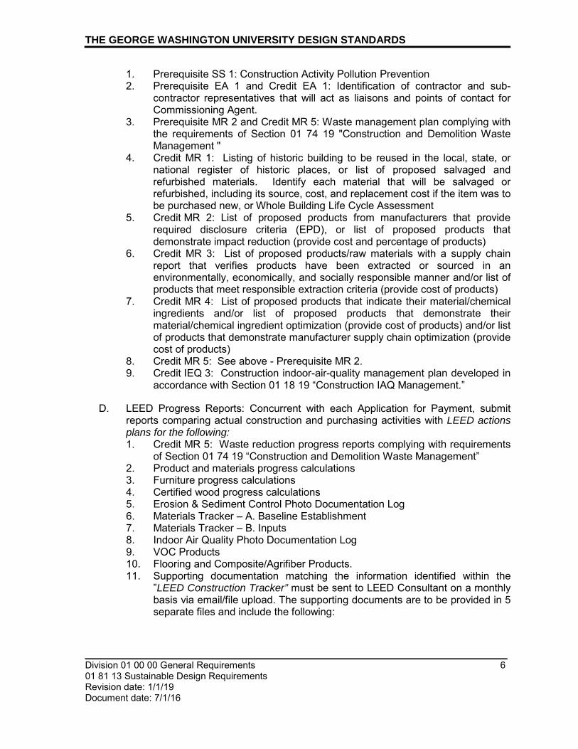
THE GEORGE WASHINGTON UNIVERSITY DESIGN STANDARDS
_________________________________________________________________________ Division 01 00 00 General Requirements 6 01 81 13 Sustainable Design Requirements Revision date: 1/1/19 Document date: 7/1/16
1. Prerequisite SS 1: Construction Activity Pollution Prevention 2. Prerequisite EA 1 and Credit EA 1: Identification of contractor and sub-
contractor representatives that will act as liaisons and points of contact for Commissioning Agent.
3. Prerequisite MR 2 and Credit MR 5: Waste management plan complying with the requirements of Section 01 74 19 "Construction and Demolition Waste Management "
4. Credit MR 1: Listing of historic building to be reused in the local, state, or national register of historic places, or list of proposed salvaged and refurbished materials. Identify each material that will be salvaged or refurbished, including its source, cost, and replacement cost if the item was to be purchased new, or Whole Building Life Cycle Assessment
5. Credit MR 2: List of proposed products from manufacturers that provide required disclosure criteria (EPD), or list of proposed products that demonstrate impact reduction (provide cost and percentage of products)
6. Credit MR 3: List of proposed products/raw materials with a supply chain report that verifies products have been extracted or sourced in an environmentally, economically, and socially responsible manner and/or list of products that meet responsible extraction criteria (provide cost of products)
7. Credit MR 4: List of proposed products that indicate their material/chemical ingredients and/or list of proposed products that demonstrate their material/chemical ingredient optimization (provide cost of products) and/or list of products that demonstrate manufacturer supply chain optimization (provide cost of products)
8. Credit MR 5: See above - Prerequisite MR 2. 9. Credit IEQ 3: Construction indoor-air-quality management plan developed in
accordance with Section 01 18 19 “Construction IAQ Management.”
D. LEED Progress Reports: Concurrent with each Application for Payment, submit reports comparing actual construction and purchasing activities with LEED actions plans for the following: 1. Credit MR 5: Waste reduction progress reports complying with requirements
of Section 01 74 19 “Construction and Demolition Waste Management” 2. Product and materials progress calculations 3. Furniture progress calculations 4. Certified wood progress calculations 5. Erosion & Sediment Control Photo Documentation Log 6. Materials Tracker – A. Baseline Establishment 7. Materials Tracker – B. Inputs 8. Indoor Air Quality Photo Documentation Log 9. VOC Products 10. Flooring and Composite/Agrifiber Products. 11. Supporting documentation matching the information identified within the
”LEED Construction Tracker” must be sent to LEED Consultant on a monthly basis via email/file upload. The supporting documents are to be provided in 5 separate files and include the following:

THE GEORGE WASHINGTON UNIVERSITY DESIGN STANDARDS
_________________________________________________________________________ Division 01 00 00 General Requirements 7 01 81 13 Sustainable Design Requirements Revision date: 1/1/19 Document date: 7/1/16
a. SSp1 - E&S Photos: Photo documentation complying with the Erosion and Sediment Control Plan. Photo documentation of installed provisions is to be provided at 3 different times (15 each).
b. Materials and Resources Product Inputs: 1) Credit MR 2: Product-specific declaration, environmental product
declarations which conform to USGBC-approved standards and have at least a cradle to gate scope, product data that complies with USGBC approved program and/or third party certified products (or products from a USGBC approved program) that demonstrate impact reduction
2) Credit MR 3: Product data from manufacturer’s raw materials suppliers and/or product data on leadership extraction practices and/or regional priority product data
3) Credit MR 4: Product data on material/chemical ingredients (Health Product Declaration, Cradle to Cradle, Declare, Product Lens, Cradle to Cradle Material Health Certificate, ANSI/BIFMA e3 Furniture Sustainability Standard, Facts, USGBC-approved program) and/or product data showing material ingredient optimization and/or product data showing manufacturer supply chain optimization
E. LEED Documentation Submittals: Prerequisite WE 2 and Credit WE 2: Product data indicating plumbing fixture flow
rates for all installed plumbing fixtures. Credit IEQ 3
a. Construction indoor air quality management plan b. Product Data for temporary filtration media. c. Construction Documentation: Six photographs at three different times
during the construction period, along with a brief description of the SMACNA approach employed, documenting implementation of the indoor-air-quality management measures, such as protection of ducts and on-site stored or installed absorptive materials.
Credit EQ 4:
d. Signed statement describing the building flush-out procedures including the dates when flush-out was begun and completed and statement that filtration media was replaced after flush-out
e. Product Data for Filtration media used during flush-out and during occupancy.
f. Report from testing and inspecting agency indicating results of indoor-air-quality testing and documentation showing compliance with indoor-air-quality testing procedures and requirements.
g. Product data for filtration media used during construction and after occupancy.
THE GEORGE WASHINGTON UNIVERSITY DESIGN STANDARDS
_________________________________________________________________________ Division 01 00 00 General Requirements 8 01 81 13 Sustainable Design Requirements Revision date: 1/1/19 Document date: 7/1/16
PART 2 - PRODUCTS
A. All product requirements to meet LEED criteria are stated in the appropriate Specification Sections.
PART 3 - EXECUTION
3.1 CONSTRUCTION WASTE MANAGEMENT
A. Credit MR 5: Comply with Division 01 Section "Construction and Demolition Waste Management "
3.2 CONSTRUCTION INDOOR AIR QUALITY MANAGEMENT
A. Credits IEQ 3: Comply with requirements indicated in Section 018119 “Construction Indoor Air Quality Management.”
END OF SECTION

_________________________________________________________________________
_________________________________________________________________________ 01 00 00 – General Requirements 1 01 81 16 VOC Limits Revision date: 1/1/19 Document date: 7/1/16
THE GEORGE WASHINGTON UNIVERSITY DESIGN STANDARDS This document provides design standards only, and is not intended for use, in whole or in part, as a specification. Consultants referencing this information must always meet all ap-plicable state and local building codes as well as all barrier free design requirements. Con-sultants must also refer to the entire set of Design Standards for additional information. Refer questions and comments regarding the content and use of this document to the George Washington University Project Manager.
SECTION 01 81 16
VOC LIMITS FOR ADHESIVES, SEALANTS, PAINTS, AND COATINGS
PART 1 - GENERAL
1.1 SUMMARY
A. This Section includes requirements for volatile organic compound (VOC) limits for adhesives sealants, paints and coatings used for the Project, in compliance with the LEED v4 rating system.
B. Related Sections:
1. Section 018113: “Sustainable Design Requirements” 2. Section 018119: “Construction Indoor Air Quality Management” 3. All technical sections in the specifications which indicate adhesive, sealant, paint, or
coating applications.
1.2 REFERENCE STANDARDS
A. General: Comply with the applicable provisions of the referenced standards except as modified by governing codes and the Contract Documents. Where a recommendation or suggestion occurs in the referenced standards, such recommendation or suggestion shall be considered mandatory. In the event of conflict of referenced standards and this specification or within the standards themselves, the more stringent standard or requirement shall govern.
1. Rule 1168 - "Adhesive and Sealant Applications", amended January 7, 2005): South Coast
Air Quality Management District (SCAQMD), State of California, www.aqmd.gov 2. Rule 1113 - "Architectural Coatings": South Coast Air Quality Management District
(SCAQMD), State of California, www.aqmd.gov 3. Green Seal Paint Standard GS-11, Green Seal, Inc., Washington, DC. 4. Green Seal Anti-Corrosive Paint Standard GS-03, Green Seal, Inc., Washington, DC 5. Green Seal Commercial Adhesive Standard GS-36, Green Seal, Inc., Washington, DC
1.3 SUBMITTALS
A. MSDS or manufacturer’s technical information for all interior applied adhesives, sealants, paints and coatings, indicating VOC content in grams/Liter (g/L).

THE GEORGE WASHINGTON UNIVERSITY DESIGN STANDARDS
________________________________________________________________________ 01 00 00 – General Requirements 2 01 81 16 VOC Limits Revision date: 1/1/19 Document date: 7/1/16
B. Documentation providing the quantity of each adhesive, sealant, paint, and coating product type used on the Project.
PART 2 - PRODUCTS
2.1 INTERIOR ADHESIVES
A. VOC Limits
1. The volatile organic compound (VOC) content of all field-applied adhesives, adhesive bonding primers, and adhesive primers used on the interior of this Project shall not exceed the limits defined in Rule 1168 - "Adhesive and Sealant Applications" of the South Coast Air Quality Management District (SCAQMD), of the State of California, effective July 1, 2005.
2. The VOC limits defined by SCAQMD are measured in grams per liter (g/L), less water and less exempt compounds.
3. General: For specified building construction related applications, the allowable VOC content is as follows:
a. Architectural Applications:
1) Indoor carpet adhesive 50 2) Carpet Pad Adhesive 50 3) Wood Flooring Adhesive 100 4) Rubber Floor Adhesive 60 5) Subfloor adhesive 50 6) Ceramic Tile Adhesive 65 7) VCT and asphalt tile adhesive 50 8) Drywall and panel adhesive 50 9) Cove base adhesive 50 10) Multipurpose construction adhesive 70 11) Structural glazing adhesive 100
b. Specialty Applications:
1) PVC welding 510 2) CPVC welding 490 3) ABS welding 325 4) Plastic cement welding 250 5) Adhesive primer for plastic 550 6) Contact Adhesive 80 7) Special Purpose Contact Adhesive 250 8) Adhesive Primer for Traffic Marking Tape 150 9) Structural Wood Member Adhesive 140 10) Sheet Applied Rubber Lining Operations 850 11) Top and trim adhesive 540
c. Substrate Specific Applications:
1) Metal to metal 30 2) Plastic foams 50 3) Porous material (except wood) 50 4) Wood 30 5) Fiberglass 80

THE GEORGE WASHINGTON UNIVERSITY DESIGN STANDARDS
________________________________________________________________________ 01 00 00 – General Requirements 3 01 81 16 VOC Limits Revision date: 1/1/19 Document date: 7/1/16
2.2 INTERIOR AEROSOL ADHESIVES
A. VOC Limits
1. The volatile organic compound (VOC) content of all field-applied aerosol adhesives, used on the interior of this Project shall not exceed the limits defined in the Green Seal standard GS-36, Commercial Adhesives. Product specific requirements are as follows:
a. Aerosol Adhesives
1) General purpose mist spray 65% VOCs by weight 2) General purpose web spray 55% VOCs by weight 3) Special purpose aerosol adhesives 70% VOCs by weight
2.3 INTERIOR SEALANTS
A. VOC Limits
1. The volatile organic compound (VOC) content of all field-applied adhesives, adhesive bonding primers, and adhesive primers used on the interior of this Project shall not exceed the limits defined in Rule 1168 - "Adhesive and Sealant Applications" of the South Coast Air Quality Management District (SCAQMD), of the State of California, effective July 1, 2005.
2. The VOC limits defined by SCAQMD are as follows. All VOC limits are defined in grams per liter, less water and less exempt compounds.
3. General: For specified building construction related applications, the allowable VOC content is as follows:
a. Sealants:
1) Architectural 250 2) Other 420
b. Sealant Primer: 1) Architectural - Nonporous 250 2) Architectural- Porous 775 3) Other 750
2.4 INTERIOR ARCHITECTURAL PAINTS
A. VOC Limits
1. The volatile organic compound (VOC) content of all field-applied paint used on the interior of this Project shall not exceed the limits defined in Rule 1113 - "Architectural Coatings" of the South Coast Air Quality Management District (SCAQMD), of the State of California, effective June 3, 2011.
2. The volatile organic compound (VOC) content of all field-applied architectural paints, used on the interior walls and ceilings of this Project shall not exceed the limits defined in the Green Seal standard GS-11, Paints. Product specific requirements are as follows: a. Paints
1) Flat 50 2) Non-Flat 150
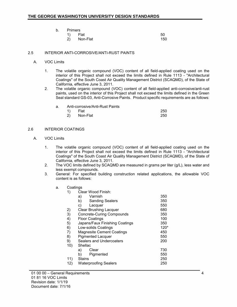
THE GEORGE WASHINGTON UNIVERSITY DESIGN STANDARDS
________________________________________________________________________ 01 00 00 – General Requirements 4 01 81 16 VOC Limits Revision date: 1/1/19 Document date: 7/1/16
b. Primers 1) Flat 50 2) Non-Flat 150
2.5 INTERIOR ANTI-CORROSIVE/ANTI-RUST PAINTS
A. VOC Limits
1. The volatile organic compound (VOC) content of all field-applied coating used on the interior of this Project shall not exceed the limits defined in Rule 1113 - "Architectural Coatings" of the South Coast Air Quality Management District (SCAQMD), of the State of California, effective June 3, 2011.
2. The volatile organic compound (VOC) content of all field-applied anti-corrosive/anti-rust paints, used on the interior of this Project shall not exceed the limits defined in the Green Seal standard GS-03, Anti-Corrosive Paints. Product specific requirements are as follows:
a. Anti-corrosive/Anti-Rust Paints
1) Flat 250 2) Non-Flat 250
2.6 INTERIOR COATINGS
A. VOC Limits
1. The volatile organic compound (VOC) content of all field-applied coating used on the interior of this Project shall not exceed the limits defined in Rule 1113 - "Architectural Coatings" of the South Coast Air Quality Management District (SCAQMD), of the State of California, effective June 3, 2011.
2. The VOC limits defined by SCAQMD are measured in grams per liter (g/L), less water and less exempt compounds.
3. General: For specified building construction related applications, the allowable VOC content is as follows:
a. Coatings
1) Clear Wood Finish: a) Varnish 350 b) Sanding Sealers 350 c) Lacquer 550
2) Clear Brushing Lacquer 680 3) Concrete-Curing Compounds 350 4) Floor Coatings 100 5) Japans/Faux Finishing Coatings 350 6) Low-solids Coatings 120* 7) Magnesite Cement Coatings 450 8) Pigmented Lacquer 550 9) Sealers and Undercoaters 200 10) Shellac
a) Clear 730 b) Pigmented 550
11) Stains 250 12) Waterproofing Sealers 250

THE GEORGE WASHINGTON UNIVERSITY DESIGN STANDARDS
________________________________________________________________________ 01 00 00 – General Requirements 5 01 81 16 VOC Limits Revision date: 1/1/19 Document date: 7/1/16
13) Waterproofing Concrete/Masonry Sealers 400 14) Wood Preservatives 350 *Note: VOC levels for Low-Solids coatings are measured in grams of VOC per liter of material, including water.
PART 3 - EXECUTION (NOT USED)
END OF SECTION

_________________________________________________________________________
_________________________________________________________________________ Division 01 00 00 – General Requirements 1 01 81 19 Construction Indoor Air Quality Management Revision date: 1/1/19 Document date: 7/1/2016
THE GEORGE WASHINGTON UNIVERSITY DESIGN STANDARDS This document provides design standards only, and is not intended for use, in whole or in part, as a specification. Consultants referencing this information must always meet all applicable state and local building codes as well as all barrier free design requirements. Consultants must also refer to the entire set of Design Standards for additional information. Refer questions and comments regarding the content and use of this document to the George Washington University Project Manager.
SECTION 01 81 19
CONSTRUCTION INDOOR AIR QUALITY MANAGEMENT
PART 1 - GENERAL
1.1 SUMMARY
A. This section includes general requirements and procedures for compliance with USGBC LEED v4 rating system.
B. Several control measures will be necessary to maintain good indoor air quality during construction. The control measures required in this project are described below.
C. This specification addresses and requires the protection of the ventilation system components during construction and cleanup of contaminated components after construction is complete.
D. These construction-related Indoor Air Quality procedures shall be included in the pre-construction and construction progress meeting agendas. In addition, the plan will require temporary ventilation in the General Conditions of the construction contract and ensure that all participants in the construction process are aware of the Indoor Air Quality procedures and understand the importance of the goals of the Indoor Air Quality Management Plan
E. The SMACNA Guidelines recommend control measures in five areas:
1. HVAC protection 2. Source control 3. Pathway interruption 4. Housekeeping 5. Scheduling
F. Related Sections:
1. Section 018113, “Sustainable Design Requirements.”

THE GEORGE WASHINGTON UNIVERSITY DESIGN STANDARDS
_________________________________________________________________________ Division 01 00 00 – General Requirements 2 01 81 19 Construction Indoor Air Quality Management Revision date: 1/1/19 Document date: 7/1/2016
1.2 REFERENCE STANDARDS
A. Sheet Metal and Air Conditioning National Contractors Association (SMACNA) IAQ Guidelines for Occupied Buildings Under Construction, 2nd Edition 2007, ANSI/SMACNA 008-2008 (Chapter 3).
1.3 SUBMITTALS
A. Credit IEQ 3: Construction Indoor Air Quality Management Plan
1. Product data for MERV 8 temporary filtration media. 2. Construction Documentation: Six photographs at three different times during
the construction period, along with a brief description of the SMACNA approach employed, documenting implementation of the indoor air quality management measures, such as protection of ducts and on-site stored or installed absorptive materials.
B. Credit IEQ 4: Indoor Air Quality Assessment
1. Signed statement describing the building air flush-out procedures including the dates when flush-out was begun and completed and statement that filtration media was replaced after flush-out.
2. Product data for filtration media used during flush-out and during occupancy. 3. Report from testing and inspecting agency indicating results of indoor air
quality testing and documentation showing compliance with indoor air quality testing procedures and requirements.
PART 2 - PRODUCTS
2.1 FILTERS
A. Return side filters shall be MERV 8 filter performance or better.
B. Central filtration (at air handling units) shall be no less than MERV 8 during construction and replaced with not less than MERV 13 filter performance or better post construction and pre-occupancy.
PART 3 - EXECUTION
3.1 HVAC PROTECTION
A. All HVAC equipment must be protected from collecting dust and odors during the construction process. The following measures shall be utilized to protect the HVAC equipment and air distribution systems.

THE GEORGE WASHINGTON UNIVERSITY DESIGN STANDARDS
_________________________________________________________________________ Division 01 00 00 – General Requirements 3 01 81 19 Construction Indoor Air Quality Management Revision date: 1/1/19 Document date: 7/1/2016
B. Return Side
1. The return side of the HVAC system (which is by definition ductwork under negative pressure) shall be shut down whenever possible during heavy construction or demolition. The return side shall also be isolated from the surrounding environment as much as possible (e.g., replace all tiles for the ceiling plenum, repair all duct and air handler leaks) and shall be fitted with temporary filters if the system must remain operational during construction. The return side shall have the heaviest work areas dampened off and return system openings shall be sealed with plastic.
C. Central Filtration
1. In areas where major dust loading is expected to impact operating HVAC systems that serve areas on the building that were affected by the construction process, install new clean media just prior to substantial completion and occupancy.
D. Supply Side
1. Where possible the supply system or branch serving the construction area should be shut off or dampened off and supply diffusers sealed in plastic. At the completion of construction prior to occupancy the contractor shall observe diffusers for deposited particulates. Clean discharge diffuser dust prior to occupancy and restore the supply side branch operation.
E. Equipment Protection
1. HVAC equipment and components (such as air handlers and return fan units) that are to be installed or that are moth balled during the construction process shall be protected from dust contamination. Entire units and their inlet and discharge openings shall be protected by plastic during the construction process when stored in areas that can be contaminated by construction odor and dust.
F. Duct Cleaning
1. If the systems exposed to construction and dust and/or motor contamination become contaminated due to inadequate protection during construction, the ducts and associated equipment should be thoroughly cleaned after construction and prior to occupancy.
3.2 SOURCE CONTROL
A. Many activities during the construction process produce odor, dust, and particulates.
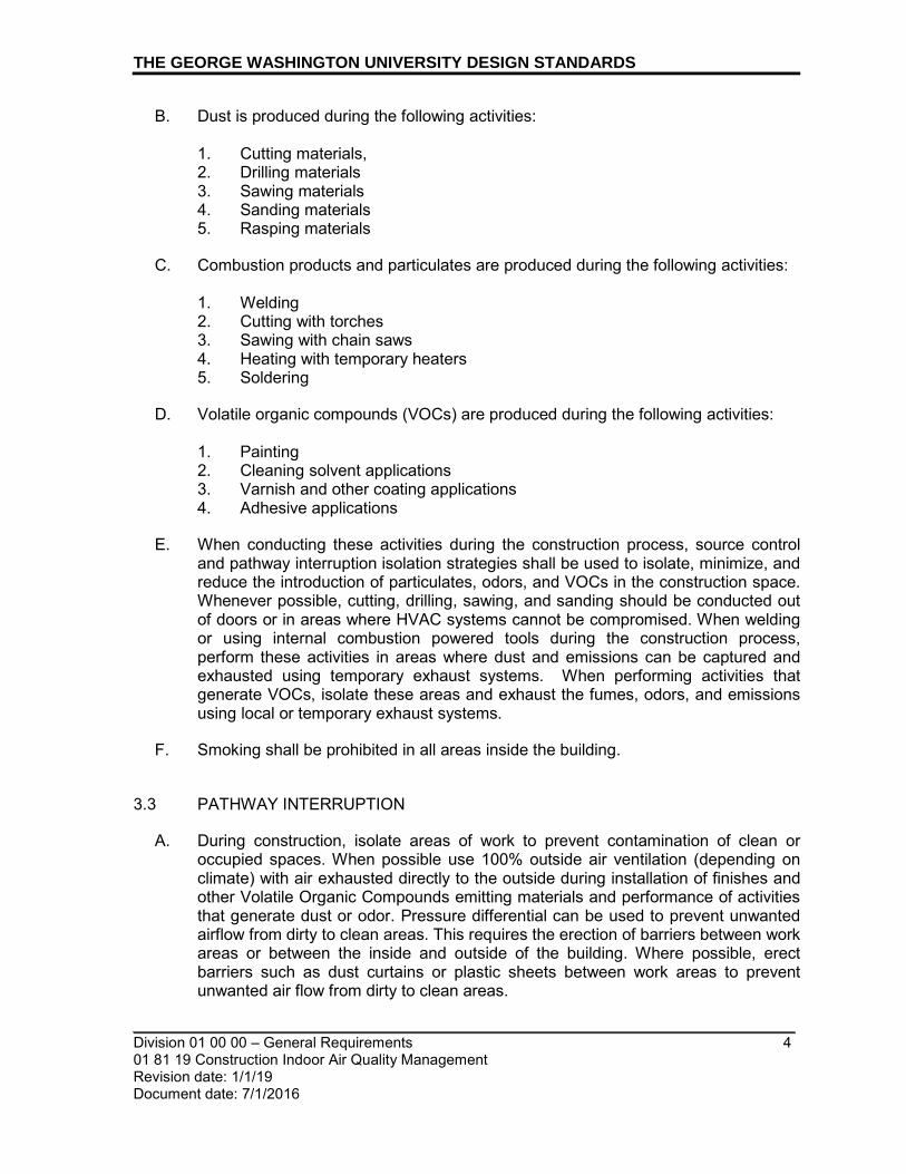
THE GEORGE WASHINGTON UNIVERSITY DESIGN STANDARDS
_________________________________________________________________________ Division 01 00 00 – General Requirements 4 01 81 19 Construction Indoor Air Quality Management Revision date: 1/1/19 Document date: 7/1/2016
B. Dust is produced during the following activities:
1. Cutting materials, 2. Drilling materials 3. Sawing materials 4. Sanding materials 5. Rasping materials
C. Combustion products and particulates are produced during the following activities:
1. Welding 2. Cutting with torches 3. Sawing with chain saws 4. Heating with temporary heaters 5. Soldering
D. Volatile organic compounds (VOCs) are produced during the following activities:
1. Painting 2. Cleaning solvent applications 3. Varnish and other coating applications 4. Adhesive applications
E. When conducting these activities during the construction process, source control and pathway interruption isolation strategies shall be used to isolate, minimize, and reduce the introduction of particulates, odors, and VOCs in the construction space. Whenever possible, cutting, drilling, sawing, and sanding should be conducted out of doors or in areas where HVAC systems cannot be compromised. When welding or using internal combustion powered tools during the construction process, perform these activities in areas where dust and emissions can be captured and exhausted using temporary exhaust systems. When performing activities that generate VOCs, isolate these areas and exhaust the fumes, odors, and emissions using local or temporary exhaust systems.
F. Smoking shall be prohibited in all areas inside the building.
3.3 PATHWAY INTERRUPTION
A. During construction, isolate areas of work to prevent contamination of clean or occupied spaces. When possible use 100% outside air ventilation (depending on climate) with air exhausted directly to the outside during installation of finishes and other Volatile Organic Compounds emitting materials and performance of activities that generate dust or odor. Pressure differential can be used to prevent unwanted airflow from dirty to clean areas. This requires the erection of barriers between work areas or between the inside and outside of the building. Where possible, erect barriers such as dust curtains or plastic sheets between work areas to prevent unwanted air flow from dirty to clean areas.

THE GEORGE WASHINGTON UNIVERSITY DESIGN STANDARDS
_________________________________________________________________________ Division 01 00 00 – General Requirements 5 01 81 19 Construction Indoor Air Quality Management Revision date: 1/1/19 Document date: 7/1/2016
3.4 HOUSEKEEPING
A. Reduce construction contaminants in the building prior to occupancy through regular space cleaning activities. Construction areas should be cleaned at regular intervals to suppress and control the distribution of contaminants generated during the construction process. Remove spills of construction materials and/or accumulated water as soon as possible.
B. All absorptive building materials and equipment to be installed, to include but not limited to drywall, carpet, ceiling tiles, insulation, shall be stored in weather tight, dry conditions, and up off floors, prior to installation.
C. Check for possible damage to the system from high humidity. All coils, air filters, and fans shall be cleaned before testing and balancing procedures are performed and especially before baseline air quality tests are conducted (if applicable).
3.5 SCHEDULING
A. Specify construction sequencing to reduce absorption of Volatile Organic Compounds or contamination by construction dust or emissions by materials that act as sinks or contaminant sources. Complete application of wet and odor-emitting materials such as paints, sealants, and coatings before “sink” materials such as ceiling tiles, carpets, insulation, gypsum products, and fabric-covered furnishings are installed. Materials that are susceptible to microbial growth shall be protected from exposed to moisture through precipitation, plumbing leaks, or condensation from the HVAC system contamination.
3.6 AIR QUALITY TESTING
A. Conduct baseline indoor-air-quality testing, after construction ends and prior to occupancy, using testing protocols consistent with the EPA's "Compendium of Methods for the Determination of Air Pollutants in Indoor Air," and as additionally detailed in the USGBC's "LEED-CI: Reference Guide."
1. Demonstrate that the contaminant maximum concentrations listed below are
not exceeded: a. Formaldehyde: 50 ppb. b. Particulates (PM10): 50 micrograms/cu. m. c. Total Volatile Organic Compounds (TVOC): 500 micrograms/cu. m. d. 4-Phenylcyclohexene (4-PH): 6.5 micrograms/cu. m. e. Carbon Monoxide: 9 ppm and no greater than 2 ppm above outdoor
levels.
2. For each sampling point where the maximum concentration limits are exceeded, conduct additional flush-out with outside air and retest the specific

THE GEORGE WASHINGTON UNIVERSITY DESIGN STANDARDS
_________________________________________________________________________ Division 01 00 00 – General Requirements 6 01 81 19 Construction Indoor Air Quality Management Revision date: 1/1/19 Document date: 7/1/2016
parameter(s) exceeded to indicate the requirements are achieved. Repeat procedure until all requirements have been met. When retesting non-complying building areas, take samples from same locations as in the first test.
3. Air-sample testing shall be conducted as follows: a. All measurements shall be conducted prior to occupancy but during
normal occupied hours and with building ventilation system starting at the normal daily start time and operated at the minimum outside air flow rate for the occupied mode throughout the duration of the air testing.
b. Building shall have all interior finishes installed including, but not limited to, millwork, doors, paint, carpet, and acoustic tiles. Non-fixed furnishings such as workstations and partitions are encouraged, but not required, to be in place for the testing.
c. Number of sampling locations will vary depending on the size of building and number of ventilation systems. For each portion of building served by a separate ventilation system, the number of sampling points shall not be less than one per 25,000 sq. ft. or for each contiguous floor area, whichever is larger, and shall include areas with the least ventilation and greatest presumed source strength.
d. Air samples shall be collected between 3 and 6 feet from the floor to represent the breathing zone of occupants, and over a minimum four-hour period.
END OF SECTION

_________________________________________________________________________
_________________________________________________________________________ Division 01 00 00 – General Requirements 1 01 91 13 General Commissioning Requirements Version 1.0 Document date: 7/1/16
THE GEORGE WASHINGTON UNIVERSITY DESIGN STANDARDS This document provides design standards only, and is not intended for use, in whole or in part, as a specification. Consultants referencing this information must always meet all applicable state and local building codes as well as all barrier free design requirements. Consultants must also refer to the entire set of Design Standards for additional information. Refer questions and comments regarding the content and use of this document to the George Washington University Project Manager.
SECTION 01 91 13
GENERAL COMMISSIONING REQUIREMENTS
PART 1 - GENERAL
1.1. SUMMARY
A. The systems installed under Divisions 21, 22, 23, and 26 as well as pieces of equipment provided under other Divisions that connect to or interface with the systems of Division 21, 22, 23, and 26 will be evaluated, started, and tested (commissioned) to ensure that each performs per the intent of the design and/or representations made relative to performance, efficiency, and suitability for application in this project.
B. The Owner will employ an independent Commissioning Authority. The Commissioning Authority is an independent and knowledgeable third party, hired to verify that the systems work as per the design intent and provide the requirements of the commissioning responsibilities as designated in this specification. The Commissioning Authority will inform the Owner of the results of the commissioning, and provide suggestions, as necessary, to correct deficiencies in observed performance or installation.
1.2. COMMISSIONING OBJECTIVES
A. Commissioning is intended to achieve the following specific objectives:
1. The Owner will ultimately inherit a building that is designed to meet the needs of the building occupants and is built and functions as designed.
2. Systems performance expectations are clearly established.
3. The users, project managers, operating personnel, contractors and designers will be protected from any dislocation created by the fragmented corrections and undocumented deficiencies.
4. Corrective actions will be made in a manner that will not compromise long-term utilization or operating expense.

THE GEORGE WASHINGTON UNIVERSITY DESIGN STANDARDS
_________________________________________________________________________ Division 01 00 00 – General Requirements 2 01 91 13 General Commissioning Requirements Version 1.0 Document date: 7/1/16
5. The Owner’s operating personnel will have the integrated system training needed to confidently operate and maintain the systems.
B. The Commissioning Authority will be employed directly by the Owner to perform commissioning duties. Sections 019113, 210800, 220800, 230800 and 260800 outline the specific commissioning responsibilities of each Contractor for that division.
1. This section of the specification describes the process for commissioning and defines the responsibilities of the construction team.
2. The commissioning process shall be applied to all equipment, components, and systems as listed in this section, including specific interfaces to and from equipment and systems provided under separate contracts.
3. Building Commissioning work is a joint team effort to verify that all systems function together properly to meet the design intent, and to document system performance parameters for fine-tuning of control sequences and operations procedures. The commissioning process shall encompass and coordinate the traditionally separate functions of system documentation, equipment start-up, control system calibration, testing and balancing, training, and performance testing. This section does not supersede other requirements of the specifications. It may, though, expand on some of them.
4. Complementary to the contractor’s responsibility to start-up the building systems, it should be noted that the Commissioning Authority will be involved. This Commissioning Authority will provide equipment-systems installation inspection and performance verification. These verifications will be a pre-requisite to final equipment and systems acceptance by the Owner as per design documents. It should be emphasized that this systems verification does not negate the contractor’s obligations to fully start-up the building systems or relieve them of any contractual obligations. The contractor's personnel shall be made available to execute all aspects of the Commissioning Process until final building acceptance by the Owner. Commissioning Program tasks and meetings may be repeated until the Owner and the A/E are satisfied and will not be fixed as one time, one chance events for the contractor.
5. The Commissioning Authority will verify equipment-systems installation and performance after the contractor provides written notice that the building equipment and systems installations have been completed, tested, and are fully operational. Upon this notification, Commissioning

THE GEORGE WASHINGTON UNIVERSITY DESIGN STANDARDS
_________________________________________________________________________ Division 01 00 00 – General Requirements 3 01 91 13 General Commissioning Requirements Version 1.0 Document date: 7/1/16
Authority will verify the installation and performance of the equipment and system(s). Subsequent installation and performance verifications will be at the Contractor’s expense. The Contractor is responsible for all systems and equipment until final acceptance by the Owner.
1.3 CONSTRUCTION TEAM RESPONSIBILITIES
Within four (4) weeks of the award of the contract, the HVAC, Plumbing and Electrical Contractors shall submit the names of their Project Manager who will be the commissioning coordinator for this project, as well as the names, addresses, phone numbers and qualifications of contractors’ representatives and factory trained manufacturers’ representatives for all equipment and systems required to participate in the commissioning process as specified in this Section.
Each Contractor, and all his sub-trades and suppliers, shall cooperate with the Commissioning Authority in carrying out the commissioning process. In this context, each Contractor shall:
1. Provide equipment and systems start-up as specified.
2. Operate equipment and systems as required for initial systems operations and for final functional performance tests, including the on-site participation of approved factory trained manufacturer’s representatives for equipment.
3. Attend commissioning meetings, and attend to action items arising from them, as required to allow the commissioning process to proceed on schedule.
4. Provide instruction and demonstrations for the Owner's designated operating staff, in conjunction with the Commissioning Authority, in order to meet all specified training requirements in this regard.
5. The contractors shall make any and all necessary corrections to systems, equipment, O&M manuals, as built drawings, and procedures as necessary to meet the design intent, contract documents, or performance requirements if errors are discovered during the commissioning process.
6. The contractors shall supply all necessary documentation, such as shop drawings, submittal data, maintenance manuals, etc. required for equipment and systems, to the Commissioning Authority for preparation of the commissioning plan, checklists, and functional performance plans.

THE GEORGE WASHINGTON UNIVERSITY DESIGN STANDARDS
_________________________________________________________________________ Division 01 00 00 – General Requirements 4 01 91 13 General Commissioning Requirements Version 1.0 Document date: 7/1/16
7. The contractors shall provide the required names, addresses and qualifications of all specified Manufacturer’s Representatives to participate in the commissioning process prior to the initial commissioning meeting.
8. Subsequent installation and performance verifications, made necessary due to required corrections after initial verification, shall be at the respective Contractor's expense.
Each Contractor shall provide to the Commissioning Authority electronic copies of the following items within 10 days of becoming available:
1. Construction schedule, including sub-schedules and milestones for all major mechanical and electrical equipment. (i.e. chillers, motor control center, air handlers, generators, VAV boxes, etc.)
2. Certified and approved start-up and testing reports for all subsystem equipment that comprise the System.
3. Control schematics and sequences of operation for the total system and all subsystems.
4. Records of required inspections for code compliance, and documentation of approved permits and licenses to operate components of the System.
5. Operating data which shall include all necessary instructions to the Owner's operating staff in order to operate the system to specified performance standards.
6. Maintenance data which shall include all necessary information required to maintain all equipment in continuous operation, such as the testing, balancing and adjusting report and the as-built drawings.
7. Written notices that building equipment and systems have been completed, tested, and are fully operational.
8. Checklist of all submitted contract deliverables such as; manuals, spare parts, training, documentation, etc.
1.4 COMMISSIONING TEAM MEMBERS
A. The members of the commissioning team consist of the Commissioning Lead Authority (CA) and support staff, the Owner’s staff, the Architect / Engineer, primary trades and other installing contractors or suppliers of equipment.
1. Commissioning Authority

THE GEORGE WASHINGTON UNIVERSITY DESIGN STANDARDS
_________________________________________________________________________ Division 01 00 00 – General Requirements 5 01 91 13 General Commissioning Requirements Version 1.0 Document date: 7/1/16
2. Owner / Developer
3. Architect / Engineer (A/E)
4. HVAC Contractor
5. Plumbing Contractor
6. Electrical Contractor
7. Fire Suppression Contractor
8. BAS Contractor
B. RESPECTIVE CONTRACTOR’S RESPONSIBILITY
1. Contractors shall review the plans and specifications with respect to the completeness in all areas relating to the Commissioning Program. This includes ensuring that there are adequate items included in the design to ensure the ability to properly test, balance, and adjust the systems and to document the performance of each piece of equipment and each system. Any items that are required for Commissioning but not shown shall be brought to the attention of the CA and A/E prior to submittal of shop drawings. Likewise, any items that are required for Commissioning but not installed shall be provided at no additional cost to the project as per design intent.
2. All contractors shall provide qualified personnel for participation in systems tests, including seasonal testing required after the initial testing.
3. Cooperate with the Commissioning Authority personnel, provide access to work, and provide adequate time in the work for commissioning tasks.
4. Include the cost for commissioning requirements in the contract price.
5. Ensure cooperation between the sub-contractors and the commissioning team.
6. Provide written documentation that the systems are complete and ready for functional testing verification.
7. Correct all contractor related deficiencies identified during any stage of the commissioning process.
8. Furnish copies of all shop drawings, manufacturers’ literature, maintenance information, or other information as may be requested.

THE GEORGE WASHINGTON UNIVERSITY DESIGN STANDARDS
_________________________________________________________________________ Division 01 00 00 – General Requirements 6 01 91 13 General Commissioning Requirements Version 1.0 Document date: 7/1/16
9. Provide qualified personnel to complete the commissioning tests, including seasonal testing.
10. Coordinate the trades as per the Commissioning Authority’s testing and pre-testing responsibilities.
11. Provide training with the assistance of the Commissioning Authority as outlined in Divisions 21, 22, 23 and 26.
12. All Contractors shall provide technical expertise to oversee, direct, and implement the correction of deficiencies found during the commissioning process. Observe the start-up and initial testing of equipment by the Contactor and Subcontractors and then all final HVAC, building automation, fire alarm, emergency power, life safety, etc. The Contractor’s personnel shall be made available to execute all aspects of the Commissioning Program until the A/E and Owner accepts the final results. Commissioning Program tasks and meetings may be repeated until the A/E and CA are satisfied and will not be fixed as one-time, one-chance events for the Contractor.
13. Note any inconsistencies or deficiencies in system operations and enforce system compliance or recommend modifications to system design which will improve system performance.
14. When equipment tests, results, and forms of documentation required by the contract documents are completed by the respective contractors, the Owner, A/E, and CA shall be notified the systems are fully operational. After such time, the CA will direct systems performance verification.
15. In the event that a performance verification test fails, the cause of failure shall be determined and rectified as soon as possible, and then re-tested.
16. Additional, specific commissioning responsibilities for each Contractor are included in the respective specification sections noted: 210800, 220800, 230800, and 260800
C. COMMISSIONING AUTHORITY’S DUTIES
1. The Commissioning Authority shall develop and submit a detailed commissioning plan that would include all system testing requirements including, pre-functional and functional testing sheets, responsibilities, O&M manual and training requirements and forms.
THE GEORGE WASHINGTON UNIVERSITY DESIGN STANDARDS
_________________________________________________________________________ Division 01 00 00 – General Requirements 7 01 91 13 General Commissioning Requirements Version 1.0 Document date: 7/1/16
2. The Commissioning Authority shall execute the Commissioning Program, through organization of all meetings, tests, demonstrations, performance verification as described within.
3. The Commissioning Authority shall be responsible for developing Pre-functional and Functional test procedures for all equipment and systems. Test procedures shall be in accordance with the manufacturer’s recommendations, and shall fully describe the system configurations and tests for each component and system. Each test procedures shall include; specific criteria to be tested for, measured test results verses design requirements, pre-functional test sheets, approved submittal and contractor required testing.
4. The Commissioning Authority shall develop and maintain the commissioning schedule that shall be updated during each commissioning meeting.
5. The Commissioning Authority shall coordinate directly with the respective contractors during the commissioning meetings (and the subcontractors) to develop the commissioning requirements and schedules.
6. The Commissioning Authority shall participate in any factory testing (ie. Air-handling factory testing) as identified by the Contract. The Commissioning Authority shall coordinate any factory testing with the contractors.
7. The Commissioning Authority shall review the record drawings and “as-built” documentation for clarity and accuracy. Any discrepancies identified during this review shall be documented and shall be returned for resubmission.
8. The Commissioning Authority shall review all operational and maintenance manuals for pre-approval prior to submission to the A/E. Any discrepancies identified during this review shall be documented and returned to the contractors for resubmission.
9. The Commissioning Authority will perform regular construction installation inspections during the construction timetable and include any identified deficiencies in the regular commissioning meetings. These items shall be reviewed and discussed during the commissioning meeting.
10. The Commissioning Authority shall direct a complete point-to-point verification of the building’s automation system once the control’s contractor submits in writing that their point-to-point is complete.
THE GEORGE WASHINGTON UNIVERSITY DESIGN STANDARDS
_________________________________________________________________________ Division 01 00 00 – General Requirements 8 01 91 13 General Commissioning Requirements Version 1.0 Document date: 7/1/16
11. Cooperate with A/E, Owner and Contractors; provide qualified personnel when scheduled.
12. Promptly notify A/E, Owner, and Contractor of irregularities or deficiencies of work, which are observed during performance of services.
13. To direct testing of all systems as defined in the Commissioning Plan and the written functional test procedures.
14. The Commissioning Authority shall work directly with the Commissioning Team to provide resolution of deficiencies and provide recommendations to the team.
15. Commissioning Authority is not authorized to:
• Release, revoke, alter, or expand requirements of Contract Documents.
• Accept any portion of work.
• Perform any duties of the Contractor.
1.5 SYSTEMS TO BE COMMISSIONED
A. HVAC
• Centrifugal Water Chillers
• Cooling Towers
• Chilled Water Pumping And Distribution System
• Condensing Boilers
• Heat Exchangers for HVAC
• Heating Hot Water Pumping And Distribution System
• Modular Indoor Central Station Air Handler Units
• Dedicated Outside Air Units
• Supply, Return and Exhaust Fans
• Air Terminal Units (*)
• Fan Coil Units

THE GEORGE WASHINGTON UNIVERSITY DESIGN STANDARDS
_________________________________________________________________________ Division 01 00 00 – General Requirements 9 01 91 13 General Commissioning Requirements Version 1.0 Document date: 7/1/16
• Unit Heaters
• Automatic Temperature Control System
• Air & Water Balancing (*)
• Air Distribution Systems
* Testing to include sampling of 20%
B. PLUMBING
• Domestic Hot Water System
• Rain Water Collection System
• Facility Natural Gas Piping
C. ELECTRICAL
• Emergency Generator
• Lighting Control Systems
• Grounding Systems
• Normal Power Systems
• Motor Control Centers / Starters
• Emergency Power System
• Switch Gear
D. FIRE SUPPRESSION
• Automatic Fire Sprinkler System
• Fire Pumping System
• Fire Alarm System**
** CA to witness AHJ testing

THE GEORGE WASHINGTON UNIVERSITY DESIGN STANDARDS
_________________________________________________________________________ Division 01 00 00 – General Requirements 10 01 91 13 General Commissioning Requirements Version 1.0 Document date: 7/1/16
1.6 COMMISSIONING PROTOCOLS
A. Overview
1. The Commissioning Authority shall develop an overview sign-off sheet for each system being commissioned. The following is a sample of the sign-off sheet required for commissioning each system. The Commissioning Authority shall review each scheduling requirement and all must be signed off prior to moving forward to the next step. Each step must be complete and signed off by the required parties prior to moving ahead (i.e. functional testing cannot start until the pre-functional checklist and deficiencies resolution is complete).
2. Pre-functional checklists are important to ensure that the equipment and systems are installed and started up as per the design documents and the manufacturer’s start-up procedures. The Commissioning Authority develops the pre-functional test sheets for each system and component to be commissioned. The pre-functional test sheets do not relieve the contractors from their duties of verifying system installation and proper system start-up. The Commissioning Authority will share the test sheets with the contractors for their review (if necessary). Once pre-functional test sheets are signed-off by the installing contractors and reviewed by the Commissioning Authority, functional performance testing may proceed without unnecessary delays. Each piece of equipment receives full pre-functional checkout by the installing contractors and verification by the CA. In general, the pre-functional testing for a given system must be successfully completed prior to formal functional performance testing of equipment or subsystems of the given system.
3. Pre-functional checklists are primarily static inspections and procedures to prepare the equipment or system for initial operation (e.g., oil levels OK, fan belt tension, labels affixed, gages in place, sensor calibration, etc.). However, some pre-functional checklist items entail simple testing of the function of a component, a piece of equipment or system (such as measuring the voltage imbalance on a three phase pump motor of a chiller system). The word pre-functional refers to before functional testing. Pre-functional checklists augment and are combined with the manufacturer’s start-up checklist.
B. FUNCTIONAL PERFORMANCE VERIFICATION
1. Functional Performance Verification (FPV) is the dynamic testing of systems (rather than just individual components) under full, part and seasonal requirements. Systems are tested under various loads and

THE GEORGE WASHINGTON UNIVERSITY DESIGN STANDARDS
_________________________________________________________________________ Division 01 00 00 – General Requirements 11 01 91 13 General Commissioning Requirements Version 1.0 Document date: 7/1/16
control sequences, such as low cooling and heating loads, component failures, unoccupied modes, fire alarm, etc. The systems are run through all the control sequences of operation and components are verified to be responding as the design intent and documents. Functional performance verification shall include; testing all sequences of operations, verification of system capacity, generating simulated signals to simulate sensor values, conducting simulated conditions to tests all loads and verify system performance during all conditions of operation and verifying design intent. In addition, each system shall be tested through all modes of operation (seasonal, occupied, unoccupied, warm-up, cool-down, part and full load). Proper responses such as power failures, freeze conditions, low-oil pressures, equipment failures, etc. shall also be tested. The Commissioning Authority develops the functional test sheets and procedures in sequential written form, coordinates the testing, and documents the testing. Each contractor is required to supply personnel to perform the functional performance testing. The Commissioning Authority will direct, oversee and witness the functional testing.
2. No system, equipment or component thereof shall be tested until the contractor has certified, in writing, that the system, equipment and / or components are complete, have been tested, adjusted and balanced and are ready for validation and performance testing. Functional Performance Verification is scheduled by the Commissioning Authority after the pre-functional testing requirements are complete and signed-off by the CA. The air balancing and water balancing must be complete and the controls must be debugged prior to the performance verification.
C. DEFERRED TESTING
1. The contractor shall be available to direct seasonal testing, tests delayed until weather or other conditions building construction is completed, required building occupancy or loading, or other conditions are suitable for the demonstration of equipment or system’s performance, as specified. These deferred tests shall be conducted in the same manner as the seasonal tests as soon as possible. Deferred testing shall be executed, documented and deficiencies corrected as specified herein for functional performance testing. Any adjustments or corrections to the O&M manuals and “As built” documents required by the results of the testing shall be made before the seasonal testing process is considered complete.
THE GEORGE WASHINGTON UNIVERSITY DESIGN STANDARDS
_________________________________________________________________________ Division 01 00 00 – General Requirements 12 01 91 13 General Commissioning Requirements Version 1.0 Document date: 7/1/16
D. TESTING DOCUMENTATION, NON-CONFORMANCE AND APPROVALS
1. The Commissioning Authority shall clearly list any outstanding items of the initial start-up and pre-functional procedures that were not completed successfully, at the bottom of the testing form or on an attached sheet. The testing form and any outstanding deficiencies shall be provided to the Owner within two days of test completion. The CA shall review the contractor’s startup testing procedures and reports and shall submit either a non-compliance report or an approval form to the contractor. The CA shall work with the contractor and others as necessary, to correct and retest all cost deficiencies or uncompleted items. The contractor shall correct all areas that are deficient or incomplete in the checklists and tests in a timely manner, and shall notify the CA as soon as outstanding items have been corrected and resubmit an updated start-up report with a Statement of Correction on the original non-compliance report. When all requirements are satisfactorily completed, the CA shall recommend approval of the startup and pre-functional testing of each system and schedule the functional testing of the equipment or system.
2. As functional performance testing progresses and a deficiency is identified, the CA shall discuss the issue with the executing contractor and the commissioning team.
a. When there is no dispute of the deficiency and the contractor accepts responsibility for correcting it, the CA shall document the deficiency and the contractor’s response and intentions and the testing shall proceed, if possible. Corrections of minor deficiencies identified may be made by the contractor during the functional performance testing, at the discretion of the CA. Every effort shall be made to expedite the testing process and minimize unnecessary delays, while not compromising the integrity of the commissioning effort.
b. During the functional performance testing of multiple units of similar equipment, the CA shall direct testing all of the equipment and components that are to be commissioned. If, under such a testing procedure, three or more, identical pieces of equipment (size alone does not constitute difference) fail to perform to the requirements of the Contract Documents (mechanically or substantively) due to manufacturing defects not allowing it to meet its submitted performance spec, all identical units may be considered unacceptable by the CA. In such case, the contractor shall provide the CA with the following:

THE GEORGE WASHINGTON UNIVERSITY DESIGN STANDARDS
_________________________________________________________________________ Division 01 00 00 – General Requirements 13 01 91 13 General Commissioning Requirements Version 1.0 Document date: 7/1/16
• Within one week of notification from the CA, the contractor or manufacturer’s representative shall examine all other identical units making a record of the findings. The findings shall be provided to the CA within two weeks of the original notice.
• Within two weeks of the original notification, the contractor shall provide the CA and the A/E a written explanation of the problem, cause of failures, etc. and proposed solution, including full equipment submittals for corrective or replacement equipment, if appropriate. The proposed solution shall not be for less than the specification requirements of the original installation.
• When approved, two examples of the proposed solution shall be installed by the contractor and the CA shall schedule and observe functional testing of the proposed solution. Upon completion of the functional testing of the proposed solution, the CA shall recommend the acceptance or disapproval of the proposed solution to the Owner.
• Upon acceptance of the proposed solution by the Owner, the contractor shall replace or repair all identical items, at their expenses and extend the warranty accordingly, if the original equipment warranty had begun. The replacement/repair work shall proceed with reasonable speed beginning within one week of approval of the proposed solution.
• Where 15% or more of a group of devices or components have failed, it shall be deemed that the entire group failed and will require retesting once the corrections have been made. The responsible contactor shall submit a notification to the CxA that the corrections have been made by the contractor and system can be retested.
c. Cost of Retesting:
• The cost for CA and/or Owner personnel to observe and direct the retesting of functional performance testing requirements necessitated because a specific pre-functional or startup test item, reported to have been

THE GEORGE WASHINGTON UNIVERSITY DESIGN STANDARDS
_________________________________________________________________________ Division 01 00 00 – General Requirements 14 01 91 13 General Commissioning Requirements Version 1.0 Document date: 7/1/16
successfully completed, but found to be incomplete or faulty, shall be the responsibility of the contractor.
• For a deficiency identified during the functional testing, not related to any pre-functional checklist or start-up fault, the CA and Owner shall direct the retesting of the equipment once all deficiencies have been rectified. However, all costs for any subsequent retesting shall be the responsibility of the contractor.
• Items left incomplete, which later cause deficiencies or delays during functional testing may result in back charges to the responsible party.
E. OPERATION AND MAINTENANCE MANUALS
1. Each contractor shall submit operational and maintenance manuals prior to training. The CA reviews the O&M manuals, documentation and as-built drawings for systems that are commissioned to verify compliance with the Specifications. Upon successful review of the corrections, the CA shall recommend approval and acceptance of these sections. The CA also reviews each equipment warranty and verifies that all requirements to keep the warranty valid are clearly stated. This work does not supersede the Architect and Engineers responsibilities according to their contract.
1.7 TRAINING REQUIREMENTS
A. Each contractor is responsible for the training requirements. The CA shall be responsible for overseeing and approving the content of training the Owner’s personnel for the equipment being commissioned. The CA will provide supplemental training if required by the Using Owner. Owner’s personnel training and orientation on equipment and systems provided by the Contractor is accomplished in three general steps.
1. Training Plan. After reviewing the specifications, and after interviewing the Owner, the Installing Contractor and Commissioning Authority (CA) shall document all the equipment for which training or orientation will be provided. This document lists, among other things, the type and number of trainees, rigor of training desired by the Owner, the primary responsible contractor, the trainer’s company and columns for tracking training

THE GEORGE WASHINGTON UNIVERSITY DESIGN STANDARDS
_________________________________________________________________________ Division 01 00 00 – General Requirements 15 01 91 13 General Commissioning Requirements Version 1.0 Document date: 7/1/16
agendas. The Commissioning Authority provides this form to the Contractor for reference.
1.8 SCHEDULING REQUIREMENTS
A. The As-Built drawings shall be updated to date and reviewed with the Commissioning Authority for approval no more than 45-days after all material is installed and in place.
B. Testing and Start-ups schedules shall be kept up to date. Advise the Commissioning Authority in writing with a minimum of 60 hours prior to commencement.
C. Notify the Commissioning Authority with a minimum of 2-weeks prior to the commencement of the TAB work for both the air and the hydronic systems. Follow requirements set forth in section 019113.
PART 2 (NOT USED)
PART 3 (NOT USED)
END OF SECTION 01 91 13

_________________________________________________________________________
_________________________________________________________________________ Division 02 00 00 – Existing Conditions 1 02 41 19 Selective Demolition Document date: 7/1/16
THE GEORGE WASHINGTON UNIVERSITY DESIGN STANDARDS This document provides design standards only, and is not intended for use, in whole or in part, as a specification. Consultants referencing this information must always meet all applicable state and local building codes as well as all barrier free design requirements. Consultants must also refer to the entire set of Design Standards for additional information. Refer questions and comments regarding the content and use of this document to the George Washington University Project Manager.
02 41 19 SELECTIVE DEMOLITION A. SUMMARY
This section contains design standards for selective demolition in existing buildings.
B. STANDARDS
1. Plaques or pin letters that need to be removed for the renovation of a building or
a space shall be delivered to the Project Manager.
END OF SECTION

_________________________________________________________________________
_________________________________________________________________________ Division 03 00 00 – Concrete 1 03 30 00 Cast-in-Place Concrete Document date: 1/1/13
THE GEORGE WASHINGTON UNIVERSITY DESIGN STANDARDS This document provides design standards only, and is not intended for use, in whole or in part, as a specification. Consultants referencing this information must always meet all applicable state and local building codes as well as all barrier free design requirements. Consultants must also refer to the entire set of Design Standards for additional information. Refer questions and comments regarding the content and use of this document to the George Washington University Project Manager.
03 30 00 CAST-IN-PLACE CONCRETE A. SUMMARY
This section contains design standards for cast-in-place concrete work.
B. QUALITY ASSURANCE
1. Comply with ACI Publications including the following:
a. ACI 117, “Specifications for Tolerances for Concrete Construction and Materials.”
b. ACI 301, “Specifications for Structural Concrete.” c. ACI 318, “Building Code Requirements for Structural Concrete.”
C. FIELD QUALITY CONTROL
1. Testing and Inspections:
i. Testing and inspection agencies performing inspections of steel reinforcement and formwork shall be responsible for inspection of raceway, miscellaneous embeds, piping sleeves and other such items in cast-in-place concrete work since clearances and other parameters related to these items are dictated by ACI 301 and 318. Thus, inspections shall conform with specifications and meet ACI requirements.
END OF SECTION

_________________________________________________________________________
_________________________________________________________________________ Division 05 00 00 – Metals 1 05 52 13 Pipe and Tube Railings Revision date: 1/1/12 Document date: 9/22/09
THE GEORGE WASHINGTON UNIVERSITY DESIGN STANDARDS This document provides design standards only, and is not intended for use, in whole or in part, as a specification. Consultants referencing this information must always meet all applicable state and local building codes as well as all barrier free design requirements. Consultants must also refer to the entire set of Design Standards for additional information. Refer questions and comments regarding the content and use of this document to the George Washington University Project Manager.
05 52 13 PIPE AND TUBE RAILINGS
A. GENERAL
All exterior railings shall be stainless steel or aluminum, with either a satin or brushed finish, unless otherwise approved. Painted railings are unacceptable due to ongoing maintenance requirements.
END OF SECTION

_________________________________________________________________________
_________________________________________________________________________ Division 06 00 00 – Woods, Plastics, and Composites 1 06 40 23 Interior Architectural Woodwork Revision date: 7/1/18 Document date: 9/22/09
THE GEORGE WASHINGTON UNIVERSITY DESIGN STANDARDS This document provides design standards only, and is not intended for use, in whole or in part, as a specification. Consultants referencing this information must always meet all applicable state and local building codes as well as all barrier free design requirements. Consultants must also refer to the entire set of Design Standards for additional information. Refer questions and comments regarding the content and use of this document to the George Washington University Project Manager.
06 40 23 INTERIOR ARCHITECTURAL WOODWORK (NON-RESIDENTIAL APPLICATIONS)
A. SUMMARY
This section contains standards for architectural woodwork including, but not limited to, the following millwork items in non-residential applications such as common area pantries, breakrooms, kitchens, mail rooms, file rooms and supply rooms: • Open cabinets with no doors • Cabinets with plastic laminate door fronts/drawers • Cabinets with wood door fronts/drawers See section 12 35 30 Residential Casework for requirements for pre-manufactured cabinets for kitchens and bathrooms in residence halls.
B. GENERAL
1. Unless otherwise noted, all cabinets share the same construction requirements.
Variables to consider include counter surface, door/drawer material, cabinet pulls, color, barrier-free access where required, and toekick material. All colors shall be selected from manufacturer’s standard color palette. See specific space standard and related sections for additional requirements.
2. Cabinet and drawer warranty: 5 years, minimum 3. Core material for use under plastic laminate or melamine:
a. Particleboard, agricultural board, or plywood. Formaldehyde-free and FSC-certified substrate is preferred where project budget can accommodate. 100% recovered and recycled wood fiber content is preferred.
4. Wood Paneling: a. Wood Species and Cut for Transparent Finish: White Maple, Quarter Sawn. b. Wood Species for Opaque Finish: Any closed-grain hardwood
5. Cabinet Components and Materials: a. Cabinet and drawer box
i. Exterior finish: plastic laminate ii. Interior finish: melamine
b. Shelves i. Shelf finish: plastic laminate ii. Shelves shall be adjustable.
c. Surface and edge treatment i. On all but concealed conditions, surfaces and edges shall be finished.
Concealed surfaces and edges are those that are not visible after installation and they include tops of cabinets, 78-inches or more AFF*, and bottoms of cabinets less than 30-inches AFF. Thus, all other edges, including, but not limited to, cabinet body and shelves made visible when

THE GEORGE WASHINGTON UNIVERSITY DESIGN STANDARDS
_________________________________________________________________________ Division 06 00 00 – Woods, Plastics, and Composites 2 06 40 23 Interior Architectural Woodwork Revision date: 7/1/18 Document date: 9/22/09
drawers and doors are open, shall be finished. * Note: if top of cabinet 78-inches or more AFF is made visible by an upper floor or staircase, it will not be considered concealed and shall, thus, be finished.
d. Door & drawer front, unless otherwise noted: i. Academic Pantries, Mail Rooms, Storage and Similar: plastic laminate
finish e. Pantry cabinets below a sink shall be ADA accessible with hinged doors that
have an integral recessed base for wheelchair access. f. Hardware:
i. Hinges for overlay doors: a.) Lifetime warranty b.) Concealed, self-closing c.) Opening: minimum 95 degrees d.) Finish: manufacturer’s bright nickel e.) Acceptable product or equivalent:
• Duomatic Hinges by Hafele America Co. ii. Drawer slides:
a.) Ball bearing slides preferred b.) Side-mounted c.) Load capacity:
• Kitchen drawers: 75 pounds/pair, minimum; ¾ extension, minimum; ball bearing slides preferred
• Desk drawers: 100 pounds/pair, minimum; full extension; ball bearing slides
• Bins and file drawers: 150 pounds/pair, minimum; full extension; ball bearing slides
d.) Finish: manufacturer’s standard electro-plated zinc e.) Acceptable products:
• Kitchen drawers: equivalent to 7434 by Accuride • Desk drawers: equivalent to 7434 by Accuride • Bins & File drawers: equivalent to 4034 by Accuride
iii. Pulls: a.) Style: 4” wire pulls b.) Material: brass or bronze c.) Finish: ANSI/BHMA finish 626/US26D, Satin Stainless Steel or
ANSI/BHMA finish 630/US32D, Satin Chrome Plated Steel d.) Acceptable products:
• Equivalent to 4484 by Stanley Hardware iv. Grommets:
a.) For GW standard built-in recycling and waste stations with solid surface countertop material and to allow for easy identification of designated bins, Designer may specify colored, plastic grommets for apertures: paper slot (blue), recycled bottle/cans (green), and trash (grey).
b.) Acceptable manufacturer: • Doug Mockett & Co, Inc.

THE GEORGE WASHINGTON UNIVERSITY DESIGN STANDARDS
_________________________________________________________________________ Division 06 00 00 – Woods, Plastics, and Composites 3 06 40 23 Interior Architectural Woodwork Revision date: 7/1/18 Document date: 9/22/09
6. Adhesives: a. As recommended by product manufacturer b. Field-applied adhesives must comply with VOC limits established by the
South Coast Air Quality Management District (SCAQMD), Rule #1168
C. RECYCLING & WASTE STATION, BUILT-IN
1. General: While GW offers a number of recycling collection variations, a standard
built-in recycling & waste station shall be located in each primary lobby on all floors. They may be also required in additional locations throughout the building, such as primary circulation paths, depending on the size and configuration of the building. Consultant to coordinate locations with Owner. At a minimum, stations shall provide the following: paper recycling; bottle and can recycling; waste disposal; and bulletin board space. Depending on the space and occupant load, it may sometimes be appropriate to provide more than one receptacle of one or more types. Optionally, stations may also include campus newspaper stacks and shelves.
2. Primary lobby locations: To maximize recycling potential, when located in a primary lobby, the recycling and waste station shall be easily seen and physically accessed from the entry. It shall be open to the space, with a bulletin board above.
3. Minimum Requirements: a. Station shall be 6’-0” wide, minimum, with a continuous solid surface counter
top, backsplash, and sidesplashes and with a base cabinet below. Counter shall be 34” AFF. Station shall be surrounded on sides and back with a gypsum board niche, unless alternate material is approved. Provide a soffit at approximately 7’-0” above at station alcove, with two recessed downlights in soffit ceiling to illuminate the recycling/waste area and the bulletin board.
b. A minimum 48” high, full-width, continuous, self-healing, neutral-colored bulletin board shall be located above the countertop on the back wall. Preference is for product/colors that allow for full width and no seams. If seams are necessary, they shall run vertically and sections should be sized equally. See 10 11 23 Bulletin Boards for additional information.
c. Counter shall be approximately 24” deep with 3 labeled apertures for bins below. The apertures shall be centered front to back, and located approximately 24” on center lengthwise, leaving 12” from the center of each end aperture and the adjacent wall. Edges of apertures shall be eased.
d. Each aperture shall have a plaque identifying the collection. The plaque for each aperture shall be 8” long x 2” deep with rounded corners. It shall be mounted with 2” clear from the front of the counter top. Plaque shall be aluminum with block capital letters, approximately 5/8” high.
e. Facing the station, from the left to right, the apertures shall be: i. left: 14” long x 2” deep slot with rounded corners combined with 3” radius
hole with “RECYCLING” plaque (for bottles/cans/paper) ii. center: 5” radius hole with “WASTE” plaque iii. right: 5” radius hole with “WASTE” plaque
f. See 06 40 23 Interior Architectural Woodwork for cabinet construction requirements. Shelves and drawers shall not be provided. Integrated finger
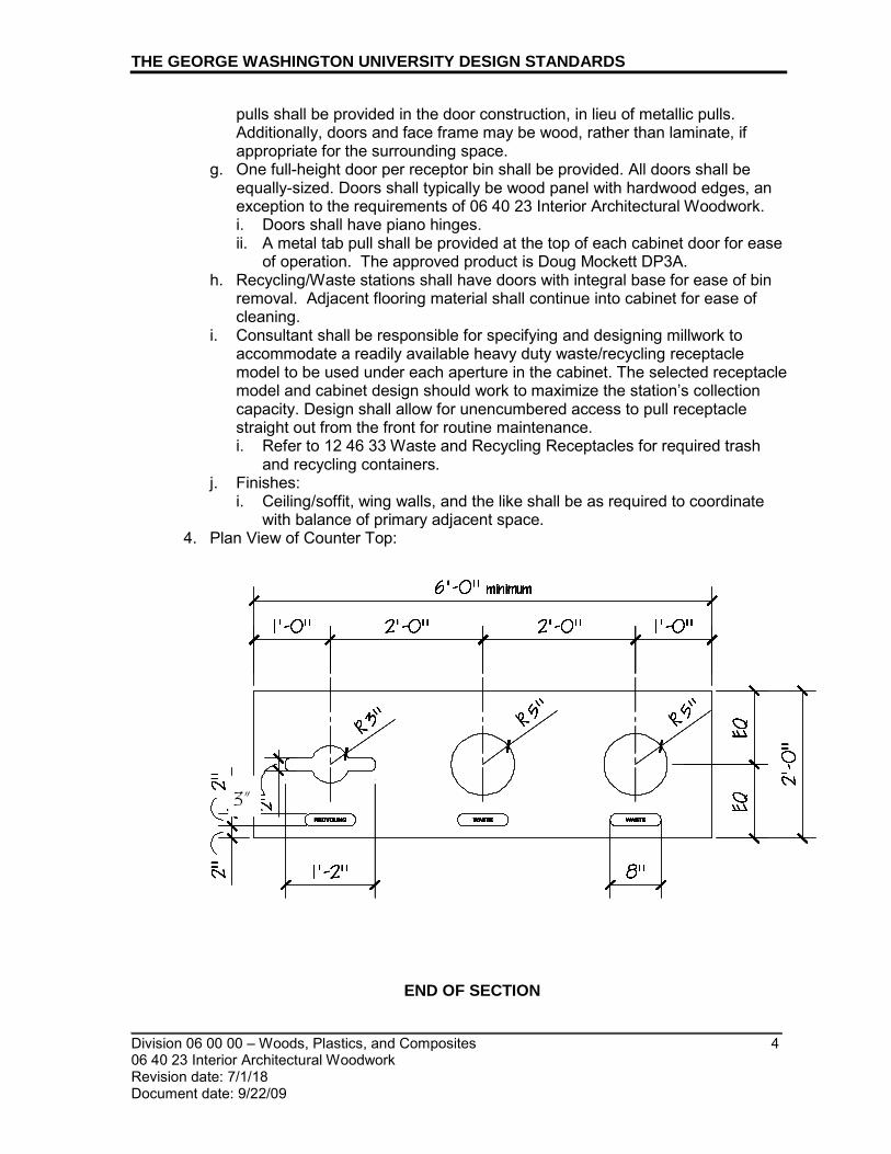
THE GEORGE WASHINGTON UNIVERSITY DESIGN STANDARDS
_________________________________________________________________________ Division 06 00 00 – Woods, Plastics, and Composites 4 06 40 23 Interior Architectural Woodwork Revision date: 7/1/18 Document date: 9/22/09
pulls shall be provided in the door construction, in lieu of metallic pulls. Additionally, doors and face frame may be wood, rather than laminate, if appropriate for the surrounding space.
g. One full-height door per receptor bin shall be provided. All doors shall be equally-sized. Doors shall typically be wood panel with hardwood edges, an exception to the requirements of 06 40 23 Interior Architectural Woodwork. i. Doors shall have piano hinges. ii. A metal tab pull shall be provided at the top of each cabinet door for ease
of operation. The approved product is Doug Mockett DP3A. h. Recycling/Waste stations shall have doors with integral base for ease of bin
removal. Adjacent flooring material shall continue into cabinet for ease of cleaning.
i. Consultant shall be responsible for specifying and designing millwork to accommodate a readily available heavy duty waste/recycling receptacle model to be used under each aperture in the cabinet. The selected receptacle model and cabinet design should work to maximize the station’s collection capacity. Design shall allow for unencumbered access to pull receptacle straight out from the front for routine maintenance. i. Refer to 12 46 33 Waste and Recycling Receptacles for required trash
and recycling containers. j. Finishes:
i. Ceiling/soffit, wing walls, and the like shall be as required to coordinate with balance of primary adjacent space.
4. Plan View of Counter Top:
RECYCLING
WASTE WASTE
RECYCLING
WASTE WASTE
RECYCLING
WASTE WASTE
RECYCLING
WASTE WASTE
RECYCLING
WASTE WASTE
RECYCLING
WASTE WASTE
RECYCLING
WASTE WASTE
RECYCLING
WASTE WASTE
RECYCLING
WASTE WASTE
RECYCLING
WASTE WASTE
RECYCLING
WASTE WASTE
RECYCLING
WASTE WASTE
RECYCLING
WASTE WASTE
RECYCLING
WASTE WASTE
RECYCLING
WASTE WASTE
RECYCLING
WASTE WASTE
END OF SECTION
3”
_________________________________________________________________________
_________________________________________________________________________ Division 06 00 00 – Woods, Plastics, and Composites 1 06 60 00 Plastic Laminate Revision date: 1/1/12 Document date: 9/22/09
THE GEORGE WASHINGTON UNIVERSITY DESIGN STANDARDS This document provides design standards only, and is not intended for use, in whole or in part, as a specification. Consultants referencing this information must always meet all applicable state and local building codes as well as all barrier free design requirements. Consultants must also refer to the entire set of Design Standards for additional information. Refer questions and comments regarding the content and use of this document to the George Washington University Project Manager.
06 60 00 PLASTIC LAMINATE
A. SUMMARY
This section contains general standards for plastic laminate. Refer to building type space standards and related specification guidelines for additional information.
B. GENERAL
1. Requirements herein apply to high pressure plastic laminates used for items
including, but not limited to, cabinets, shelves, and countertops. 2. Plastic laminate shall be GreenGuard Indoor Air Quality Certified. 3. Laminate color to be selected from manufacturer’s standard color palette. 4. Approved manufacturers, or approved equal:
a. Wilsonart International b. Formica Corporation c. Nevamar Corporation
5. Adhesive a. Clear-drying type recommended by laminate manufacturer b. Must comply with VOC limits established by the South Coast Air Quality
Management District (SCAQMD), Rule #1168
C. INSTALLATION 1. Plastic laminate installation shall follow manufacturer’s specifications including,
but not limited to, instructions for joints and seams.
END OF SECTION

_________________________________________________________________________
_________________________________________________________________________ Division 06 00 00 – Woods, Plastics, and Composites 1 06 61 13 Cultured Marble Revision date: 1/1/12 Document date: 7/1/10
THE GEORGE WASHINGTON UNIVERSITY DESIGN STANDARDS This document provides design standards only, and is not intended for use, in whole or in part, as a specification. Consultants referencing this information must always meet all applicable state and local building codes as well as all barrier free design requirements. Consultants must also refer to the entire set of Design Standards for additional information. Refer questions and comments regarding the content and use of this document to the George Washington University Project Manager.
06 61 13 CULTURED MARBLE FABRICATIONS
A. SUMMARY
This section contains general standards for cultured marble countertops with cultured marble integral sinks and backsplashes. Refer to Residence Hall space standards and related specification guidelines for additional information.
B. GENERAL
1. Requirements herein apply to cultured marble used for bathroom vanity
countertops in residence halls. 2. Material: Cast, filled polymer 3. Performance Requirements:
Property Requirement Method
Color fastness No change - 200 hours ANSI Z-124
Wear and Cleaning Passes ANSI Z-124
Impact resistance No cracks or chips ANSI Z-124
Stain resistance Passes ANSI Z-124
Chemical resistance Passes ANSI Z-124
Drain Fitting Connection Passes ANSI Z-124.3
Loads on lavatory tops Passes ANSI Z-124.3
Thermal shock resistance Passes ANSI Z-124.3
Cigarette burn test Passes ANSI Z-124.3
4. System Requirements: a. Performance Standards: Cultured marble countertop shall comply with ANSI
Z-124.1, 2, 3, 4 /ANSI A -112.19.7 and 82 and applicable building codes. 5. Vanity Tops With Integral Backsplashes:
a. Cast polymer cultured marble; ¾” thick; using adhesives suitable for cast polymer products
b. Vanity top and backsplash shall be one piece, without joints c. Vanity Top Dimensions: As indicated on drawings d. Backsplashes: 4” high

THE GEORGE WASHINGTON UNIVERSITY DESIGN STANDARDS
_________________________________________________________________________ Division 06 00 00 – Woods, Plastics, and Composites 2 06 61 13 Cultured Marble Fabrications Revision date: 1/1/12 Document date: 7/1/10
e. Sidesplashes: To be provided at all adjoining walls, 4” high f. Edge: Dripless edge, with approximately 1/8” rise g. Color to be selected from manufacturer’s standard color palette
6. Integral Sinks: a. Cast polymer cultured marble b. Large, recessed bowl with overflow; Oval, 20” X 17”
7. Allowable Tolerances: a. Variation in component size: ± 1/4" b. Location of openings: ± 1/8” from indicated position
8. Acceptable Manufacturers: Subject to compliance with requirements, products of a member of the International Cast Polymer Association shall be specified.
9. Acceptable products and manufacturers, or approved equal: a. Equivalent to Solid White 103 by Virginia Marble Manufacturers, Inc.
C. ACCESSORIES
1. General: Provide accessories required for complete installation, including trim
strips, mildew-resistant sealant, and adhesive.
D. INSTALLATION 1. Cultured marble countertop system shall be fully coordinated with installation of
vanity cabinets and plumbing. 2. Provide concealed blocking and anchor securely to walls.
END OF SECTION

_________________________________________________________________________
_________________________________________________________________________ Division 06 00 00 – Woods, Plastics, and Composites 1 06 61 16 Solid Surfacing Fabrications.doc Fabrications Revision date: 4/1/19 Document date: 9/22/09
THE GEORGE WASHINGTON UNIVERSITY DESIGN STANDARDS This document provides design standards only, and is not intended for use, in whole or in part, as a specification. Consultants referencing this information must always meet all applicable state and local building codes as well as all barrier free design requirements. Consultants must also refer to the entire set of Design Standards for additional information. Refer questions and comments regarding the content and use of this document to the George Washington University Project Manager.
06 61 16 SOLID SURFACING FABRICATIONS
A. SUMMARY
This section contains general standards for solid surfacing requirements. Refer to building type space standards and related specification guidelines for additional information.
B. GENERAL
1. Requirements herein apply to solid surfacing used for items including, but not
limited to, countertops and window sill stools/aprons. a. All bathroom windows in residence halls shall have a sloped solid surface sill.
2. Homogenous, mineral-filled acrylic and polymer resin 3. Thickness for counters: ¾”, unless otherwise required 4. Thickness for window sill stools: ½” unless otherwise required 5. Adhesive
a. As recommended by solid surface material manufacturer b. Adhesive must comply with VOC limits established by the South Coast Air
Quality Management District (SCAQMD), Rule #1168 6. Color to be selected from manufacturer’s standard color palette. 7. Approved products, or approved equal
a. Corian by DuPont b. Wilsonart International c. Formica Corporation
END OF SECTION

_________________________________________________________________________
_________________________________________________________________________ Division 07 00 00 – Thermal and Moisture Protection 1 07 33 63 Vegetated Roofing Revision date: 1/1/14 Document date: 1/1/11
THE GEORGE WASHINGTON UNIVERSITY DESIGN STANDARDS This document provides design standards only, and is not intended for use, in whole or in part, as a specification. Consultants referencing this information must always meet all applicable state and local building codes as well as all barrier free design requirements. Consultants must also refer to the entire set of Design Standards for additional information. Refer questions and comments regarding the content and use of this document to the George Washington University Project Manager.
07 33 63 VEGETATED ROOFING
A. SUMMARY
This section contains general standards for green roof systems. Refer to related specification guidelines for additional information.
B. REFERENCE STANDARDS Reference standards include, but are not limited to, the following: 1. ASTM E 2400-06, Standard Guide for Selection, Installation, and Maintenance of
Plants for Green Roof Systems 2. ASTM E 2399-05, Standard Test Method for Maximum Media Density for Dead
Load Analysis on Green Roof Systems 3. ASTM E 2398-05, Standard Test Method for Water Capture and Media Retention
of Geocomposite Drain Layers for Green Roof Systems 4. ASTM E 2369-05, Standard Test Method for Saturated Water Permeability of
Granular Drainage Media (Falling Head Method) for Green Roof Systems 5. System Provider’s standard and specific technical specifications and
recommendations 6. Methods of Soil Analysis, American Society of Agronomy (1996) “MSA”. 7. Test Methods for the Examination of Composting and Compost (latest version)
“TMECC”. 8. Recommended Chemical Soil Testing Procedures, North Central Region
Publication #221 “RCSTP”. 9. USDA Handbook #60
C. SUSTAINABILITY 1. Sustainability is among the highest priorities at GW. Green roofs provide the
following environmental benefits and thus shall be considered for all projects unless a cool roof is to be installed: a. Reduced stormwater runoff quantities b. Improved water quality of stormwater runoff c. Reduced urban heat island effect through reduction in roof surface
temperature d. Extended lifespan of the roofing system by protecting membrane from direct
sunlight and extreme temperatures e. Increased insulation R-values for roof system f. Cooling effect from evapotranspiration of plants
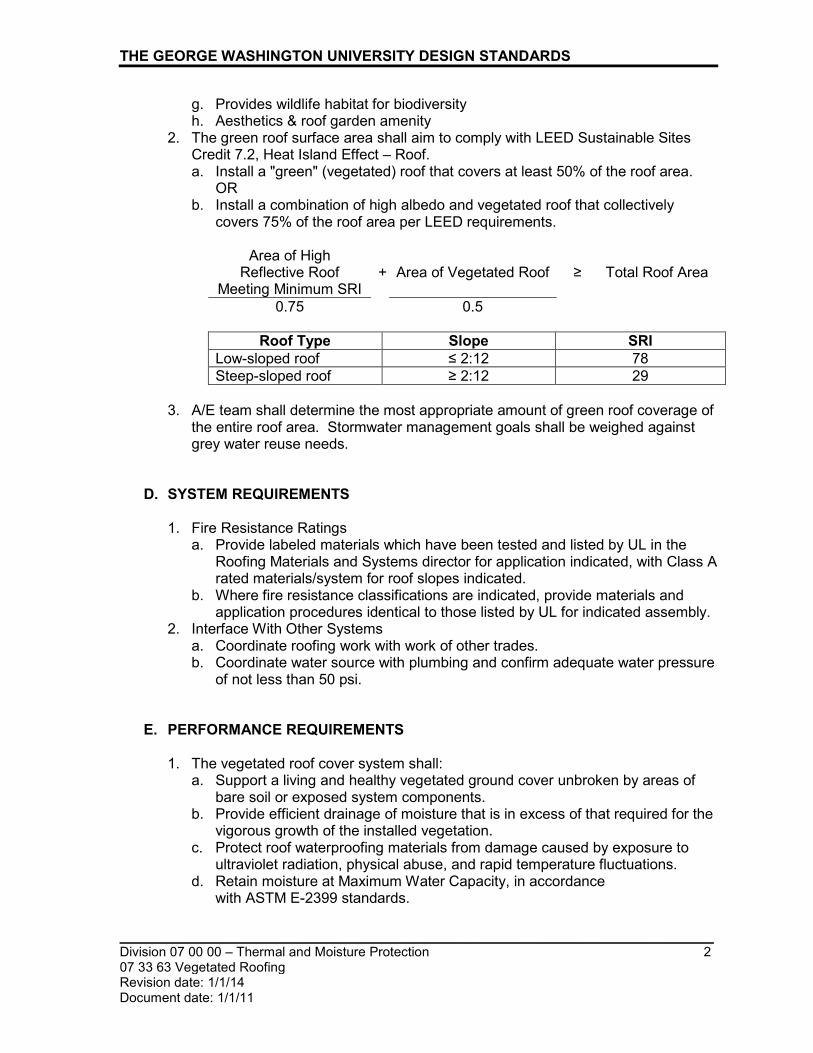
THE GEORGE WASHINGTON UNIVERSITY DESIGN STANDARDS
_________________________________________________________________________ Division 07 00 00 – Thermal and Moisture Protection 2 07 33 63 Vegetated Roofing Revision date: 1/1/14 Document date: 1/1/11
g. Provides wildlife habitat for biodiversity h. Aesthetics & roof garden amenity
2. The green roof surface area shall aim to comply with LEED Sustainable Sites Credit 7.2, Heat Island Effect – Roof. a. Install a "green" (vegetated) roof that covers at least 50% of the roof area.
OR b. Install a combination of high albedo and vegetated roof that collectively
covers 75% of the roof area per LEED requirements.
Area of High Reflective Roof
Meeting Minimum SRI
+
Area of Vegetated Roof
≥
Total Roof Area
0.75 0.5
Roof Type Slope SRI Low-sloped roof ≤ 2:12 78 Steep-sloped roof ≥ 2:12 29
3. A/E team shall determine the most appropriate amount of green roof coverage of
the entire roof area. Stormwater management goals shall be weighed against grey water reuse needs.
D. SYSTEM REQUIREMENTS 1. Fire Resistance Ratings
a. Provide labeled materials which have been tested and listed by UL in the Roofing Materials and Systems director for application indicated, with Class A rated materials/system for roof slopes indicated.
b. Where fire resistance classifications are indicated, provide materials and application procedures identical to those listed by UL for indicated assembly.
2. Interface With Other Systems a. Coordinate roofing work with work of other trades. b. Coordinate water source with plumbing and confirm adequate water pressure
of not less than 50 psi.
E. PERFORMANCE REQUIREMENTS 1. The vegetated roof cover system shall:
a. Support a living and healthy vegetated ground cover unbroken by areas of bare soil or exposed system components.
b. Provide efficient drainage of moisture that is in excess of that required for the vigorous growth of the installed vegetation.
c. Protect roof waterproofing materials from damage caused by exposure to ultraviolet radiation, physical abuse, and rapid temperature fluctuations.
d. Retain moisture at Maximum Water Capacity, in accordance with ASTM E-2399 standards.
THE GEORGE WASHINGTON UNIVERSITY DESIGN STANDARDS
_________________________________________________________________________ Division 07 00 00 – Thermal and Moisture Protection 3 07 33 63 Vegetated Roofing Revision date: 1/1/14 Document date: 1/1/11
e. The dead weight and the saturated dead weight of the vegetated roof cover system shall not exceed the guidance weights per ASTM E-2397.
F. GENERAL 1. Green Roof Type: The green roof shall be the extensive type, sedum mat
system, and 85% - 90% pre-grown consisting of the standard mix of pre-planted and pre-grown vegetation inter-planted with 30% native plant species plug materials. Refer to Green Roof Systems Component section, below, for additional information. The green roof system shall include all components specified as directed by the green roof system provider, landscaper, or project engineer. The work shall include installation of edge treatments, pavers, decorative ballast, and slip-sheet, if specified.
2. The green roof system is intended to be used without major irrigation. a. A lockable wall hydrant shall be provided for initial and periodic irrigation and
to serve maintenance needs. 3. Proof of Structural Load Bearing Capacity: An engineer’s report shall confirm
that the load bearing capacity of the structure is compatible with the green roof system. a. For retrofits of existing buildings, the capacity of the existing structure to carry
the additional load must be confirmed. In addition, the quality of the existing waterproofing needs must be assessed before placing the green roof system on top.
4. The entire roof assembly shall comply with FM Global requirements. Green roof systems shall comply with FM Global green roof requirements. Refer to FM Global Data Sheet 1-35 “Green Roof Systems”. All submittals for new roof, re-roof, and re-cover projects shall be submitted to FM Global for review and approval. Refer to FM Global’s “Plan Review and Construction Project Guidelines for The George Washington University, Washington, DC” for additional information. a. High Rise Building Green Roof Setbacks: A minimum 3’-0” setback at the
parapet and adjacent to penthouse walls is acceptable provided that the project provides an “FM approved” roof system and that the vegetative roof is not serving as the critical ballast for the roof membrane.
6. The roofing system shall meet all applicable code requirements and requirements of testing agencies including Underwriters Laboratories and FM Global.
7. The roof system shall be accessible to allow for inspection and maintenance. Ease of maintenance shall be an important consideration in the roof design.
8. Waterproofing Membrane: a. Coordination with Waterproofing Provider: Before commencement of the
waterproofing installation, the waterproofing installer and the green roof system provider shall meet with Owner’s representative to discuss project sequence and methods for protecting and controlling access to the work and to review shop drawings to establish compliance with the specifications. Coordination meeting will determine how the waterproofing will be protected between the time it is certified by the Waterproofing Provider as watertight and the time that installation of the vegetated cover system can begin.

THE GEORGE WASHINGTON UNIVERSITY DESIGN STANDARDS
_________________________________________________________________________ Division 07 00 00 – Thermal and Moisture Protection 4 07 33 63 Vegetated Roofing Revision date: 1/1/14 Document date: 1/1/11
b. Waterproofing membrane components and accessories must be obtained as a single-source from the waterproofing provider to ensure total system compatibility and integrity.
c. Waterproofing membrane performance shall be verified for meeting the green roof manufacturer’s specifications prior to installation of green roof system.
d. The waterproofing membrane shall be compatible with the electronic leak detection system (EFVM) so as not to interfere with low voltage transmission.
e. The waterproofing membrane manufacturer shall approve the green roof system for use on their waterproofing product. Any components such as root protectors, protection layers, etc required by the waterproofing manufacturer for their warranties shall be specified by the waterproofing membrane manufacturer.
f. The waterproofing membrane shall be covered by a separate warranty issued by the waterproofing membrane manufacturer.
9. Accessories: a. All components or accessories related to the green roof shall be approved by
the roof membrane manufacturer for compatibility with their system.
G. GREEN ROOF SYSTEM COMPONENTS 1. Green roof system components shall include, at a minimum, the following
components: adhered roof waterproofing membrane; foundation/protection layer; separation/root barrier protection course; aeration layer; drainage/water retention layer; filter fabric/geotextile; growth media layer; plants; wind protection; metal edge restraint; precast concrete pavers; drain access chambers, and miscellaneous accessories as required for complete installation. All components or accessories shall be approved by the green roof system manufacturer for compatibility with their roof system. a. Plants - Pre-grown sedum mats:
i. Sedum mats shall be 85% - 90% covered when delivered to the project. ii. Sedum mats shall be suitable for climate and application and composed
of sedum varieties that are appropriate plantings including 30% native plant species plugs interplanted for the project's micro-climate (exposure to wind, light, shade, drainage, etc) thus proven successful on extensive living roofs in the mid-Atlantic region.
iii. Base sedum varieties shall be supplemented with accent plants to support diversity in the micro habitat and add visual appeal.
iv. Vegetation shall be installed in accordance with the landscape design.
H. PAVERS
a. Description: Precast concrete pavers shall be used to provide the green roof with vegetation and growth-free border zones around the building perimeter, roof-mounted equipment and any roof-top structures per FM Global green roof systems requirements “FM Global Property Loss Prevention Data Sheets 1-35 Green Roof Systems”. Pavers near the roof edge shall be strapped down to avoid any potential for removal due to strong wind. Recommend

THE GEORGE WASHINGTON UNIVERSITY DESIGN STANDARDS
_________________________________________________________________________ Division 07 00 00 – Thermal and Moisture Protection 5 07 33 63 Vegetated Roofing Revision date: 1/1/14 Document date: 1/1/11
conducting a wind design to verify the areas of concern. Pavers shall meet LEED Sustainable Sites Credit 7.2 Heat Island Effect – Roof requirement of SRI > 78.
2. Heavyweight Concrete Walkway Pavers: Heavyweight, hydraulically pressed, concrete units manufactured for use as roof- or plaza-deck pavers a. Size
i. Roof Perimeter Edge: Nominal 36” square by 2” thick ii. Equipment and Interior Edges: Nominal 24” square by 2” thick
b. Acceptable product and manufacturer: i. Prest Roof and Plaza Pavers by Hanover Architectural Products, Inc.
c. Finish: Tudor with beveled edges d. Color: Glacier White
3. Heavyweight Concrete Drainage Pavers : Heavyweight, hydraulically pressed, concrete units manufactured for use as roof- or plaza-deck pavers a. Size: To match adjacent pavers b. Approved product and manufacturer:
i. Drainage paver with holes by Hanover Architectural Products c. Finish: Tudor with beveled edges d. Color: Glacier White
4. Paver Supports: a. Paver manufacturer’s standard EPDM rubber, paver support assembly,
including adjustable or stackable pedestals, shims: i. Approved product and manufacturer:
a.) Hanover High-Tab Pedestal with Flexible Leveling Shims
I. INSTALLATION 1. General:
a. Green roof installation shall be performed by a green roof system provider such as a landscape company that specializes in vegetated roof assembly installation work.
b. The green roof system provider shall provide a quality control specialist to observe critical aspects of the installation.
c. Only products and methods acceptable to membrane roofing manufacturer shall be utilized.
2. A thorough inspection of the membrane and flashings must be completed and approved before the “vegetative overburden” is installed over the waterproofing membrane system.
3. Environmental Requirements: a. General: Proceed with planting work only when existing and forecasted
weather conditions will permit work to be performed, when beneficial and optimum results may be obtained, and in accordance with manufacturer’s specifications and warranty requirements.
b. Follow plant supplier’s recommendations regarding planting requirements and optimum conditions.
4. Electronic Field Vector Mapping (EFVM)/Leak Detection: a. Prior to green roof installation, comprehensive roof leak detection shall be
performed to confirm water-tightness. Installation shall be performed only

THE GEORGE WASHINGTON UNIVERSITY DESIGN STANDARDS
_________________________________________________________________________ Division 07 00 00 – Thermal and Moisture Protection 6 07 33 63 Vegetated Roofing Revision date: 1/1/14 Document date: 1/1/11
after appropriate waterproofing system with the proper taper to allow for drainage, has been installed and tested.
b. Technician shall be certified in EFVM testing method and have a minimum of 1 year experience providing testing for projects of similar scale and scope.
c. Provide a second test one year after the entire system has been installed. 5. All drains shall be fitted with inspection/maintenance boxes and grilles, built up to
ensure access at roof surface.
J. QUALITY ASSURANCE
1. All specified and required items directly or indirectly related to the green roof are
to be provided by one system manufacturer and one installation contractor. Items include paths and walkways, patios and railing systems, irrigation, and pavers (or ballast).
2. Manufacturer’s technical representative shall conduct inspections prior to, during and at completion of installation.
3. Contractor shall carry out recommendations of manufacturer’s representative. 4. Written reports of inspections shall be provided to Owner.
K. WARRANTY 1. Manufacturer shall warrant that the green roof system will perform its function of
containing plant growth media for a period of twenty (10) years from the date of substantial completion. a. The warranty shall guaranty 80% foliage cover after a period of two years so
long as the vegetated cover assembly is maintained according to the green roof provider’s requirements. Bare areas shall be reseeded as necessary.
b. The warranty shall include provisions to repair or replace specified materials or work that has failed within the warranty period. System failures covered by the warranty shall include, but are not limited to, the following: i. Failure of the vegetated cover system to support a robust ground cover ii. Loss of soil permeability iii. Development of anaerobic conditions in the profile iv. Loss of drainage capacity v. Development of soil pathogens vi. Deleterious changes in pH vii. Slope related instability of the vegetated cover system viii. Wind or water erosion of the vegetated cover system
c. In the event of a leak, the warranty shall require the green roof provider to pay for the cost of removing the vegetated cover, exposing and repairing the membrane, and restoring the vegetated cover provided: i. The green roof provider approves the method and technician for leak
location. ii. A representative of the green roof provider is present to observe the
removal of the vegetated cover. iii. The leak is attributed to physical damage caused by activities of a
Vegetated Roof System Contractor licensed by the green roof provider, or
THE GEORGE WASHINGTON UNIVERSITY DESIGN STANDARDS
_________________________________________________________________________ Division 07 00 00 – Thermal and Moisture Protection 7 07 33 63 Vegetated Roofing Revision date: 1/1/14 Document date: 1/1/11
agents or representatives of the System Provider (either during construction or subsequent maintenance).
2. The green roof system shall have a two-year workmanship warranty. The warranty shall include green roof maintenance visits to ensure proper plant root establishment, plant coverage and general maintenance of the vegetated roof system via feeding, weeding, and monitoring conditions for long-term viability. Maintenance-related activities and components shall be redone, removed or replaced if determined to be defective within two years after substantial completion.
3. Temporary spray irrigation will be required during the first full growing season. The design and implementation of temporary irrigation is the responsibility of the green roof system installer.
END OF SECTION

_________________________________________________________________________
_________________________________________________________________________ Division 07 00 00 – Thermal and Moisture Protection 1 07 50 00 Roofing Revision date: 10/1/18
Document date: 9/20/2010
THE GEORGE WASHINGTON UNIVERSITY DESIGN STANDARDS This document provides design standards only, and is not intended for use, in whole or in part, as a specification. Consultants referencing this information must always meet all applicable state and local building codes as well as all barrier free design requirements. Consultants must also refer to the entire set of Design Standards for additional information. Refer questions and comments regarding the content and use of this document to the George Washington University Project Manager.
07 50 00 ROOFING
A. SUMMARY
This section contains general standards for roofing. Refer to related space standards and specification guidelines for additional information.
B. HISTORIC BUILDINGS 1. GW’s Foggy Bottom campus is comprised of a unique collection of historic
buildings that vary distinctly in architectural character and feature both flat and sloped roofs. In keeping with GW’s Historic Preservation Plan, these buildings must retain their historic nature and any landmark designations. Thus, consultants must select roofing materials that retain the original character of these buildings. Parameters such as project budget, function, ease of maintenance, energy efficiency and sustainability shall also be considered in the selection of roofing materials.
2. Renovation, repair, replacement and maintenance of historic roofs shall comply with The District of Columbia Historic Preservation Guidelines - Roofs on Historic Buildings. Projects must also be approved by DC’s Historic Preservation Office.
3. As budget allows and where appropriate, GW prefers the utilization of terne-coated copper and copper, subject to review by DC’s Historic Preservation Office.
C. PRE-DESIGN MEETING
1. Prior to the beginning of design, GW and the Project Architect shall have a
meeting to determine the most appropriate roof membrane for the project. Factors to take into consideration shall include existing roof system elements (if applicable, for major renovation projects), preferred roof membrane materials described herein, sustainability/life cycle assessment, performance, ease of maintenance, project budget and other requirements described in this section. The architect shall proceed with a roof design that adheres to the agreed upon solution and approval by GW.
D. GENERAL
1. The roof system shall adhere to the following requirements:
a. The roof design shall provide slope (minimum code compliant) to ensure rapid and dependable drainage to prevent ponding of water for prolonged periods and minimize potential interior damage in the event of a roof leak.
THE GEORGE WASHINGTON UNIVERSITY DESIGN STANDARDS
_________________________________________________________________________ Division 07 00 00 – Thermal and Moisture Protection 2 07 50 00 Roofing Revision date: 10/1/18
Document date: 9/20/10
i. Pitch roof by either sloping structure (preferred method) or by using tapered insulation.
b. The roofing membrane shall have a durable surface and high puncture resistance. The insulation shall have high compressive strength.
c. The roofing system and all other components connected to it (i.e., mechanical equipment and wall assemblies) shall be designed to allow for reroofing in the future.
d. Re-roof or re-cover roofing systems shall correct any thermal deficiencies and contribute towards achieving a high-performance building envelope.
e. Ease of maintenance shall be an important consideration in the design of the roof. The roofing system shall be accessible in order to allow for proper inspection and maintenance.
f. The roofing system shall be designed based on the planned activities and equipment scheduled directly beneath the roof.
g. The entire roof assembly shall comply with FM Global requirements and all documentation for new roof, re-roof, and re-cover projects shall be submitted to FM Global for review and approval. Refer to FM Global’s “Plan Review and Construction Project Guidelines for The George Washington University, Washington, DC” for additional information. i. Roof design have FM Class A rating and meet FM rating I-870
2. The roofing system shall meet all applicable code requirements and requirements of testing agencies including Underwriters Laboratories and FM Global.
3. Waterproofing membrane components and accessories must be obtained as a single-source from the waterproofing provider to ensure total system compatibility and integrity.
5. Adhesives and sealants shall comply with VOC limits of California South Coast Air Quality Management District (SCAQMD) Rule #1168.
6. Warranty: a. Roofing manufacturer warranty shall be 20 years minimum, no dollar limit,
including wind speed coverage up to 90 mph peak gusts, covering inspection and service necessary to correct roof leaks resulting from normal wear and tear, faulty materials or improper workmanship for warranty period.
b. The entire roof assembly is to be covered by the manufacturer’s warranty including, without limit, the insulation and any cover board, the roofing material, the flashings, any through-penetration systems or fabrications, equipment mounting curbs, etc. Roof warranties shall cover the installed system, not simply the roofing materials.
c. Roof installation warranty shall cover a two year minimum period and follow manufacturer’s warranty requirements.
7. The roofing contractor shall be certified with the Roof Consultants Institute (RCIA).
8. Inspections: a. Inspections by roofing system manufacturer’s technical representative shall
be conducted prior to, during, and at completion of installation to evaluate roofing application.

THE GEORGE WASHINGTON UNIVERSITY DESIGN STANDARDS
_________________________________________________________________________ Division 07 00 00 – Thermal and Moisture Protection 3 07 50 00 Roofing Revision date: 10/1/18
Document date: 9/20/10
E. PERFORMANCE REQUIREMENTS
1. Provide installed roofing system and base flashings that remain watertight; do not
permit water infiltration; and resist specified uplift pressures, thermally induced movement, and exposure to weather without failure.
2. Provide roofing materials that are compatible with one another under conditions of service and application required, as demonstrated by the roofing manufacturer based on testing and field experience.
3. The roofing system shall be successfully tested by a qualified testing and inspection agency to resist uplift pressures and must comply with all applicable requirements in FM Approvals.
4. The roofing system shall meet all fire resistance rating requirements. 5. The roofing system design shall be identical to systems that have been
successfully tested by a qualified testing and inspecting agency to resist uplift pressures according to industry reference standards including ASCE 7.
6. FMG Approvals Listing: Roofing assembly materials including roofing membrane, base flashings, and component materials shall be identified with FMG Approvals markings.
7. All materials shall be from one manufacturer.
F. SUSTAINABILITY 1. Sustainability is among the highest priorities at GW. Cool roofs provide the
following environmental benefits and thus shall be provided for all major roof replacements and new roof construction unless a green roof is to be installed (Refer to 07 33 63 Vegetated Roofing for green roof requirements): • Reduced urban heat island effect through reduction in roof surface
temperature • Reduced energy use for cooling during the summer season. • Extended life span of the roofing system by protecting roof against extreme
temperatures swings. a. The renovation of historic building roofs shall incorporate sustainable design
solutions. Analyze whether or not a cool roof or green roof is appropriate for a historic building. Ensure that the historic character, structural integrity, and function of the roof are not compromised by sustainable design elements.
2. The roof surface material shall comply with LEED Sustainable Sites Credit 7.2, Heat Island Effect – Roof. a. Roof surface materials shall have a Solar Reflectance Index (SRI) equal to or
greater than the values in the table below for a minimum of 75% of the roof surface:
Roof Type Slope SRI Low-sloped roof ≤ 2:12 78 Steep-sloped roof ≥ 2:12 29
OR
b. Install a "green" (vegetated) roof that covers at least 50% of the roof area.

THE GEORGE WASHINGTON UNIVERSITY DESIGN STANDARDS
_________________________________________________________________________ Division 07 00 00 – Thermal and Moisture Protection 4 07 50 00 Roofing Revision date: 10/1/18
Document date: 9/20/10
OR
c. Install a combination of high albedo and vegetated roof that collectively
covers 75% of the roof area per LEED requirements.
Area of High Reflective Roof
Meeting Minimum SRI
+
Area of Vegetated Roof
≥
Total Roof Area
0.75 0.5
Roof Type Slope SRI Low-sloped roof ≤ 2:12 78 Steep-sloped roof ≥ 2:12 29
d. Refer to LEED 2009 Edition Reference Guide for additional information and
SRI calculation standards. 3. The roof and insulation system shall comply with ASHRAE 90.1 energy
requirements. 4. The roof surfacing product shall be Energy Star-qualified and certified by the
Cool Roof Rating Council (CRRC) www.coolroofs.org. 5. Consider the use of low-sloped roofs for stormwater retention. Captured
rainwater may be reused on-site for toilet flushing or irrigation.
G. ROOF MEMBRANE TYPES
For new construction and major renovation of buildings, the following membrane roofing types are acceptable, subject to approval by GW: 1. Hot fluid-applied rubberized asphalt membrane (new construction/major
renovations) a. Cold fluid-applied rubberized asphalt membrane shall be provided where low
odor applications are required 2. TPO (over metal deck, wood deck or where the parapet is at least 3 feet high) 3. PVC, KEE or PVC with KEE plasticizing agent (existing building roofs with wood
underlayment) a. Green roofs that use PVC membranes shall ensure that the membranes are
fabricated using a “spread-coat” method wherever possible. 4. EPDM roofing systems are not acceptable.
H. HOT FLUID-APPLIED RUBBERIZED ASPHALT MEMBRANE
1. Horizontal membrane waterproofing system complete with flashings and terminations shall include a primer and 2-ply hot, fluid applied, reinforced rubberized asphalt membrane. System materials shall include membrane, moisture-resistant insulation, filter fabric, precast concrete pavers and paver supports as required.
THE GEORGE WASHINGTON UNIVERSITY DESIGN STANDARDS
_________________________________________________________________________ Division 07 00 00 – Thermal and Moisture Protection 5 07 50 00 Roofing Revision date: 10/1/18
Document date: 9/20/10
a. Substrate must provide membrane with code compliant slope. b. Installation: Ensure concrete substrate is fully cured and dry, according to
ASTM testing methods, prior to application of the membrane. c. For green roof applications, a root barrier must be provided to protect the
membrane. Refer to 07 33 63 Vegetated Roofing for green roof requirements. i. Root barrier shall be a tested 30-mil thermoplastic membrane to ensure
a robust roofing system. d. Acceptable Products and Manufacturers:
i. 790-11EV by Henry Company ii. Monolithic Membrane 6125 by American Hydrotech iii. Equal product by Cetco
e. Fabric Reinforcement: Manufacturer’s recommended polyester fabric reinforcement sheet, an inorganic spun bonded polyester fabric sheet with sufficient porosity, shall be provided to allow good interply bonding between layers of waterproofing membrane.
f. The hot fluid applied rubberized asphalt membrane product shall contain an inert clay filler to enable the product to be resistant to acids (fertilizers, building washes and acid rain).
g. Insulation: Extruded-polystyrene board insulation complying with ASTM C578 i. Acceptable manufacturers:
a.) DiversiFoam Products b.) Dow Chemical Company c.) Owens Corning d.) Pactiv Corporation e.) T. Clear Corporation
h. Filter Fabric: i. Water-permeable polyolefin or polypropylene fabric; water and ultra-violet
resistant ii. Provide product and manufacturer as recommended by insulation
manufacturer iii. Acceptable products and manufacturers or approved equal:
a.) Confil D689 by International papers Co. b.) Fabrene VIE by Fabrene, Inc. c.) Rufon P3B by Philips Fibers Corp.
i. Ballast: i. Precast concrete pavers:
a.) Basis of Design: Prest Roof and Plaza Pavers by Hanover Architectural Products, Inc.
a) Color: Glacier White; SRI 85 b) Size: Nominal 24” square by 2” thick; 22 psf minimum to 25
psf maximum c) Finish: Heavy Tudor
j. Accessories: i. Provide all required roof accessories including, but not limited to, flashing,
reinforcing sheet, primer, protection/separation sheet, drainage board and paver pedestals. Provide quantity of paver pedestals, and thicknesses and quantity of leveling plates, as required to provide level installation of top surface of pavers.

THE GEORGE WASHINGTON UNIVERSITY DESIGN STANDARDS
_________________________________________________________________________ Division 07 00 00 – Thermal and Moisture Protection 6 07 50 00 Roofing Revision date: 10/1/18
Document date: 9/20/10
ii. Miscellaneous accessories shall include, but are not limited to, joint tapes, adhesives, splicing cement and other as recommended by membrane manufacturer.
I. COLD-FLUID APPLIED RUBBERIZED ASHPALT MEMBRANE 1. Membrane Description: 2-ply, fast-curing, one-component, cold-applied, moisture
cure, solvent free, elastomeric, seamless waterproofing membrane system designed to provide a cold, low-odor alternative to hot applied rubberized asphalt membrane systems. a. Substrate shall provide membrane with code-compliant slope. b. Installation: Ensure concrete substrate is fully cured and dry, according to
ASTM testing methods, prior to application of the membrane. c. For green roof applications, a root barrier shall be provided to protect the
membrane. Refer to 07 33 63 Vegetated Roofing for green roof requirements. i. Root barrier shall be a tested 30-mil thermoplastic membrane to ensure
a robust roofing system. d. Acceptable Products and Manufacturers:
i. CM100 by Henry Company, or equal product by American Hydrotech or Cetco, subject to review and approval by GW
e. Structure: Cast-in-Place Concrete Deck/Composite Deck: Precast Concrete i. Lightweight insulating concrete is not an acceptable substrate.
f. Provide all required roof membrane system components in accordance with the membrane manufacturer’s specifications including, but not limited to, the following: i. Flashing Membrane ii. Expansion Joints iii. Crack Treatment iv. Fabric Reinforcement v. Protection Course composed of the following:
a.) Protection Fabric b.) SBS Modified-Bitumen flashing c.) Continuously Extruded Flexible Twin Wall Board d.) Prefabricated Drain Board e.) Rigid Insulation Board f.) Asphaltic rigid board for use when overburden will consist of asphalt
concrete pavement vi. Termination sealant compatible with roofing and waterproofing
membranes and substrate vii. Securement bars of continuous aluminum, stainless steel or galvanized
metal viii. Filter Fabric ix. Roof Ballast:
a.) See 07 33 63 Vegetated Roofing for green roof requirements, or b.) Precast concrete pavers: Provide quantity of paver pedestals, and
thicknesses and quantity of leveling plates, as required to provide level installation of top surface of pavers.
THE GEORGE WASHINGTON UNIVERSITY DESIGN STANDARDS
_________________________________________________________________________ Division 07 00 00 – Thermal and Moisture Protection 7 07 50 00 Roofing Revision date: 10/1/18
Document date: 9/20/10
c.) Basis of Design: Prest Roof and Plaza Pavers by Hanover Architectural Products, Inc.
a) Color: Glacier White; SRI 85 b) Size: Nominal 24” square by 2” thick; 22 psf minimum to 25
psf maximum c) Finish: Heavy Tudor
g. Accessories: i. Miscellaneous accessories shall include, but are not limited to, joint tapes,
adhesives, splicing cement and other as recommended by membrane manufacturer.
J. ETHYLENE INTERPOLYMER (KEE) MEMBRANE 1. Provide a fully adhered, ethylene interpolymer (KEE) alloy, reinforced with knitted
polyester fabric, roofing membrane with heat-welded seams. Roof membrane assembly shall include membrane sheet, protection board, vapor retarder, roof insulation, insulation accessories and walkways. a. All products and components shall be provided by the same manufacturer. b. Ketone Ethylene Esther (KEE) Sheet:
i. Comply with ASTM D6754-02, fabric reinforced and fabric backed ii. Basis of Design Product:
a.) FiberTite by Seaman Corporation, or comparable approved product a) Membrane For Cool Roof or Green Roof Applications:
i) 36 mil FiberTite ii) 45 mil FiberTite-SM
b.) Flex c. Exposed Face Color (Cool Roofs): White with SRI not less than 78 d. Provide membrane auxiliary membrane roofing materials recommended by
roofing system manufacturer for intended use and compatible with membrane roofing, including, but not limited to the following: sheet flashing, bonding adhesive, slip sheet, metal termination bars, metal battens, fasteners, and miscellaneous accessories such as sealers, sheet flashings, T-joint covers, lap sealants, termination reglets, and other accessories. i. Liquid-type auxiliary membrane roofing materials shall comply with VOC
limits of authorities having jurisdiction ii. Adhesives and sealants that are not on the exterior side of weather
barrier shall comply with VOC limits when calculated according to 40 CFR59, Subpart D (EPA method 24).
K. TPO MEMBRANE
1. Basis of Design Manufacturer and Product:
a. Firestone, white reflective, 80 mil thick, heat weldable membrane horizontally and vertically. ISO 95+GL insulation board shall be installed and tapered to achieve the proper water flow. Insulation board shall be installed using a single-ply, LVOC bonding adhesive and water block sealant to prevent water instrusion with the ISOGUARD HD ½” cover board.

THE GEORGE WASHINGTON UNIVERSITY DESIGN STANDARDS
_________________________________________________________________________ Division 07 00 00 – Thermal and Moisture Protection 8 07 50 00 Roofing Revision date: 10/1/18
Document date: 9/20/10
L. PVC MEMBRANE
1. PVC sheet membrane assembly including PVC sheet, substrate boards, vapor retarder, roof insulation, insulation accessories and walkways. a. Provide one of the following:
i. PVC sheet complying with ASTM D 4434, Type II, Grade I, glass fiber-reinforced, felt-backed. a.) Acceptable Products and Manufacturers, or equal subject to
compliance with requirements: a) Sika Sarnafil G410-15 b) Flex
b.) Thickness: 60 mils, nominal c.) Exposed Face Color: White with SRI not less than 78
ii. PVC sheet complying with ASTM D 4434, Type IV, fabric reinforced and fabric-backed. a.) Acceptable Products and Manufacturers, or equal subject to
compliance with requirements: a) BondCote Corporation
b.) Thickness: 60 mils, nominal c.) Exposed Face Color: White with SRI not less than 78
b. Provide auxiliary membrane roofing materials recommended by roofing system manufacturer for intended use, and compatible with membrane roofing including, but not limited to, the following: sheet flashing, bonding adhesive, slip sheet, metal termination bars, metal battens, fasteners, and miscellaneous accessories such as sealers, sheet flashings, T-joint covers, lap sealants, termination reglets, and other accessories. i. Liquid-type auxiliary membrane roofing materials shall comply with VOC
limits of authorities having jurisdiction ii. Adhesives and sealants that are not on the exterior side of weather
barrier shall comply with VOC limits when calculated according to 40 CFR59, Subpart D (EPA method 24).
M. PVC WATERPROOFING MEMBRANE (FOR GREEN ROOF APPLICATIONS)
1. Single-Ply PVC Waterproofing Membrane: Thermoplastic PVC waterproofing
membrane with non-woven fiberglass reinforcing and closed-cell foam backing layer a. Acceptable Products and Manufacturers, or approved equal:
i. Sika Sarnafil; G476-20 SA Waterproofing Membrane ii. Flex
b. Waterproofing Membrane: Self-adhering, cold-applied composite sheet membrane, 80 mils thick PVC thermoplastic membrane with closed cell foam backing for total thickness of 120 mils
c. Vapor Barrier: Self-adhering membrane consisting of rubberized asphalt binder and HDPE facer
d. Primers, Surface Conditioners, Fillers and Sealers: Asphalt based, ,ASTM D41, as required by waterproofing membrane manufacturer for substrate
e. Flashing Membrane: PVC membrane, 80 mils thick, with woven fiberglass reinforcing:

THE GEORGE WASHINGTON UNIVERSITY DESIGN STANDARDS
_________________________________________________________________________ Division 07 00 00 – Thermal and Moisture Protection 9 07 50 00 Roofing Revision date: 10/1/18
Document date: 9/20/10
i. Acceptable Products: Sarnafil G410-20 thermoplastic flashing membrane f. Termination Bar: Manufacturer’s standard metal termination bar, prepunched
to permit proper spacing of fasteners g. Insulation: Extruded polystyrene board insulation complying with ASTM
C578, square or shiplap edge, Type VII, 60-psi minimum compressive strength: Type IV, 25-psi minimum compressive strength
N. ROOF COATING (COOL ROOFS)
1. General: Architect shall specify a high reflective roof surface complying with the
following: a. Solar reflectivity and thermal emittance in accordance with ASTME903,
ASTM E408, and ASTM C1371. b. LEED requirements for Sustainable Sites Credit 7.2, Heat Island Effect - Roof
- compliant with reflectivity (ASTM E-903) and emissivity (ASTM E-408); SRI value = 78 minimum.
a. Radiative property values that are rated by a laboratory accredited by the Cool Roof Rating Council (CRRC).
b. U.S. EPA Energy Star-qualified. c. Comply with accelerated weathering test conditions per ASTM D4798.
2. Thermoplastic Membrane Roofing: Architect shall select a membrane with a white surface color that meets the cool roof coating criteria mentioned above, without need for application of an additional coating.
O. ROOF INSULATION
1. General: Provide preformed roof insulation boards that comply with
requirements and referenced standards, selected from manufacturer's standard sizes and of thicknesses as required. a. Rigid insulation shall not be manufactured with or contain CFC or HCFC
agents. b. Comply with current ASHRAE 90.1 requirements for the minimum required
prescriptive R-value for roof insulation. 2. Insulation:
a. Polyisocyanurate Board Insulation: Insulation board consisting of rigid closed-cell polyisocyanurate foam core bonded to top and bottom layers of felt or non-asphaltic fiber glass mat, complying with ASTM C 1289, Type II, Class I, Grade 2.
b. Extruded Polystyrene Insulation: For use with hot fluid-applied rubberized asphalt waterproofing membrane; Comply with ASTM C578.
3. Tapered Insulation: a. Provide in thicknesses, slopes, and configurations where required to create
positive slope to drainage locations where roof structure is not sloped. b. Factory-tapered insulation board consisting of rigid, closed-cell
polyisocyanurate foam core bonded to top and bottom layers of non-asphaltic fiber glass mat; complying with ASTM C1289, Type II
4. Saddles, crickets, edge strips and other: a. Provide preformed saddles, crickets, tapered edge strips, and other insulation
in shapes and thicknesses as required for sloping to drains.

THE GEORGE WASHINGTON UNIVERSITY DESIGN STANDARDS
_________________________________________________________________________ Division 07 00 00 – Thermal and Moisture Protection 10 07 50 00 Roofing Revision date: 10/1/18
Document date: 9/20/10
5. Insulation Accessories: a. Roof insulation accessories shall be recommended by insulation
manufacturer for intended use and compatible with membrane roofing.
P. COVER BOARD 1. Cover Board shall be a high density, prefabricated board manufactured for use
as a recover board over insulation and be compatible with the membrane roofing system; one of the following types: a. Asphaltic board: Fiberglass-faced asphalt board; smooth faces b. Insulation board with reinforced perlite core and asphalt emulsion coating on
top surface c. Glass-mat reinforced, water-resistant gypsum board
2. Acceptable Products and Manufacturers, or equal: i. DensDeck by Georgia-Pacific Gypsum, LLC ii. Securock by USG Corporation iii. Re-Cover Board s/s by Henry Company iv. Duraboard by Johns Mansville/Invinsa Roof Board by Johns Manville
Q. ROOF MAINTENANCE PAVERS
1. Pavers shall have a minimum SRI value of 78 to meet requirements of LEED
Sustainable Sites Credit 7.2, Heat Island Effect – Roof. 2. Pavers to be placed on pedestal system to maintain level surface. 3. Basis of Design: Prest Roof and Plaza Pavers by Hanover Architectural
Products, Inc. i. Color: Glacier White; SRI 85 ii. Size: Nominal 24” square by 2” thick; 22 psf minimum to 25 psf maximum iii. Finish: Heavy Tudor
R. ROOF MAINTENANCE WALKWAY PADS 1. Provide walkway pads in locations where needed to create a complete traffic
path to and from roof access door and window washing anchors and completely surround roof-mounted mechanical equipment. Walkway pad shall be slip-resistant, manufactured as a traffic pad for foot traffic and acceptable to roofing system manufacturer. a. PVC/PVC with KEE Additive Membrane: Provide factory-formed, nonporous,
heavy-duty, slip-resistant, surface-textured walkway pads or rolls, approximately 20-mils thick.
b. Pad Size: Manufacturer’s standard i. Color: To be selected by Architect from manufacturer’s full standard color
range; visible color, not black.
S. WATERPROOFING MEMBRANE TESTING 1. The waterproofing membrane shall be tested for leaks by either flood testing the
area or Electronic Field Vector Mapping:

THE GEORGE WASHINGTON UNIVERSITY DESIGN STANDARDS
_________________________________________________________________________ Division 07 00 00 – Thermal and Moisture Protection 11 07 50 00 Roofing Revision date: 10/1/18
Document date: 9/20/10
a. Flood Testing: Completed roofs shall be tested for leaks and flood testing. a. Electronic Field Vector Mapping (EFVM)/Leak Detection (Green Roofs w/
PVC/KEE Membrane Only): i. Prior to green roof installation, comprehensive roof leak detection shall be
performed to confirm water-tightness. Refer to GW Design Standards, 07 33 63, Vegetated Roofing, for additional information.
END OF SECTION

_________________________________________________________________________
_________________________________________________________________________ Division 07 00 00 – Thermal and Moisture Protection 1 07 92 00 Joint Sealants Revision date: 1/1/12 Document date: 7/1/10
THE GEORGE WASHINGTON UNIVERSITY DESIGN STANDARDS This document provides design standards only, and is not intended for use, in whole or in part, as a specification. Consultants referencing this information must always meet all applicable state and local building codes as well as all barrier free design requirements. Consultants must also refer to the entire set of Design Standards for additional information. Refer questions and comments regarding the content and use of this document to the George Washington University Project Manager.
07 92 00 JOINT SEALANTS
A. SUMMARY
This section contains design standards for joint sealants necessary to properly seal and weatherproof all interior and exterior joints such as perimeter of door, window and louver frames; expansion and control joints in masonry and concrete; exterior insulation and finish system; between plumbing fixtures and walls; around penetrations in walls, ceilings, and floors; and any other work as required.
For related work refer to the following specification guidelines for additional information: • 06 40 23 Interior Architectural Woodwork • 08 11 13 Hollow Metal Doors and Frames • 08 40 00 Entrances, Storefronts, and Curtain Walls • 08 51 13 Aluminum Windows • 08 80 00 Glazing • 09 29 00 Gypsum Board
B. GENERAL
1. General Material Requirements: a. Provide specific materials recommended by the manufacturer for the
particular application or condition of use in each case as required to fulfill system requirements.
b. The hardness or consistency of elastomeric sealants shall be determined in consultation with the manufacturer and consider joint movement and weather exposure for joint size indicated. i. Sealant characteristics must be consistent with exposure to wear,
abrasion, and vandalism. ii. Sealants exposed to traffic shall have strength and elasticity
characteristics to resist damage from traffic and indentation by stiletto heels.
c. Back-up materials or joint filler shall be installed as required or detailed. d. Joint filler materials shall comply with manufacturer specifications and
consider joint conditions, movement, and proposed sealants. e. Joint sealants containing toxic or hazardous substances are not permitted.

THE GEORGE WASHINGTON UNIVERSITY DESIGN STANDARDS
_________________________________________________________________________ Division 07 00 00 – Thermal and Moisture Protection 2 07 92 00 Joint Sealants Revision date: 1/1/12 Document date: 7/1/10
f. VOC content of interior sealants and sealant primers shall comply with the following limits for VOC content when calculated per 40 CFR 59, Part 59, Subpart D (EPA Method 24): i. Architectural Sealants: 250 g/L. ii. Sealant Primers for Nonporous Substrates: 250 g/L iii. Sealant Primers for Porous Substrates: 775 g/L
g. Suitability for Contact with Food: Where elastomeric sealants are indicated for joints that will come in repeated contact with food, provide products that comply with 21 CFR 177.2600.
2. Performance Requirements: a. Design, manufacture, and install joint sealants to establish and maintain
airtight and water-resistant continuous joint seals without staining or deteriorating joint substrates.
b. Stain-Test-Response Characteristics: Sealant shall be non-staining to porous substrates when tested in accordance with ASTM C1248.
c. Compatibility and Adhesion: Provide only joint sealants, primers, and other substances which are compatible with each other and joint surfaces and will adhere to joint surfaces.
d. Range of Hardness: In general, sealants shall have range of hardness suitable for degree of movement and weather exposure in particular application.
3. Color Requirements: a. Architect shall make final color selection. b. Sealant materials exposed to view shall match colors of adjacent surfaces.
i. Provide custom colors to match Architect’s samples. c. Provide custom-blended colors as needed for color matching as follows:
i. Sealant Joints in Masonry: Match mortar color ii. Joints in Cast Stone: Match color of matrix iii. Joints Around Doors, Windows, and Openings: Match color of adjacent
wall material iv. Joints in Tile: Match grout color v. Joints in Floors: Match control sample provided by Architect
d. Fully concealed joints: i. As selected by Architect from manufacturer’s full color range which has
best overall performance characteristics required for application
C. PRODUCTS Subject to compliance with system requirements, joint sealants that shall be incorporated in the Project include, but are not limited to, the following: 1. Silicone Sealant
a. One part, nonsag, neutral cure, silicone sealant, capable of ±50% joint movement complying with ASTM C719, ASTMC920, Type S, Grade NS,
b. Acceptable products and manufacturers or equal: i. 795 Silicone Building Sealant; Dow Corning Corp. ii. Silpruf SCS2000; GE Silicones iii. 864; Pecora Corp iv. Spectrum 3; Tremco, Inc.

THE GEORGE WASHINGTON UNIVERSITY DESIGN STANDARDS
_________________________________________________________________________ Division 07 00 00 – Thermal and Moisture Protection 3 07 92 00 Joint Sealants Revision date: 1/1/12 Document date: 7/1/10
c. Locations: Typical exterior joints in vertical surfaces and in horizontal non-traffic surfaces
2. Polyurethane Sealant a. Multi-component, polyurethane-based elastomeric sealant, self-leveling and
with compatible non-sag sealant for use on slopes, capable of ±25% joint movement complying with ASTM C719, ASTM C920, Type M, Grade P, Class 25. Uses T, M, A, and as applicable to joint substrates indicated, O.
b. Acceptable products and manufacturers or equal: i. Urexpan NR-200; Pecora Corp. ii. SL 2 Sealant; Sonneborn Building Products Div., ChemRex Inc. iii. THC 900/901; Tremco, Inc.
c. Locations: Typical exterior and interior horizontal traffic joints
3. Mildew-Resistant Silicone Joint Sealant a. One part, non-sag, elastomeric silicone sealant containing fungicide for
mildew resistance complying with ASTM C920, Type S, Grade NS, Class 25 b. Acceptable products and manufacturers or equal:
i. 786 Mildew Resistant; Dow Corning Corp. ii. Sanitary 1700; GE Silicones iii. 898 Silicone Sanitary Sealant; Pecora Corp. iv. Tremsil 200; Tremco
c. Locations: Interior use in wet locations, and all toilet and shower rooms, plumbing fixtures, lavatory countertops, etc.
4. Latex Joint Sealant
a. Latex acrylic emulsion compound, permanently flexible, non-staining and non-bleeding, paintable, conforming to ASTM C834.
b. Acceptable products and manufacturers or equal: i. AC-20 Acrylic Latex; Precora Corporation ii. Sonolac; Sonneborn Building Products Div, ChemRex, Inc. iii. Tremflex 834; Tremco, Inc.
c. Locations: Typical interior joints in vertical surfaces and in horizontal non-traffic surfaces, except as otherwise noted; paintable
5. Acoustical Sealant a. Manufacturer's standard non-sag, paintable, non-staining latex sealant
complying with ASTM C 834. Product shall effectively reduce airborne sound transmission through perimeter joints and openings in building construction as demonstrated by testing representative assemblies according to ASTM E 90.
b. Acceptable products and manufacturers or equal: i. AC-20 FTR Acoustical and Insulation Sealant; Pecora Corporation ii. Sheetrock Acoustical Sealant; USG Corporation
c. Locations: Interior acoustically sealed joints exposed or exposed above ceilings

THE GEORGE WASHINGTON UNIVERSITY DESIGN STANDARDS
_________________________________________________________________________ Division 07 00 00 – Thermal and Moisture Protection 4 07 92 00 Joint Sealants Revision date: 1/1/12 Document date: 7/1/10
6. Acoustical Sealant for Concealed Joints a. Manufacturer’s standard, nondrying, nonhardening, nonskinning, nonstaining,
gunnable, synthetic-rubber sealant recommended for sealing interior concealed joints to reduce airborne sound transmission.
b. Acceptable products and manufacturers or equal: i. BA-98; Percora Corporation ii. Tremco Acoustical Sealant; Tremco
c. Locations: Concealed interior acoustically sealed joints at metal stud tracks 7. Expanding Foam Sealant
a. Manufacturer’s standard preformed, precompressed, impregnated open-cell foam sealant manufactured from high-density urethane foam impregnated with a nondrying, water-based polymer-modified acrylic emulsion; factory-produced in precompressed sizes and in roll or stick form to fit joint widths indicated, depth as recommended by manufacturer for size of joint:
b. Properties: Permanently elastic, mildew-resistant, nonmigratory, nonstaining, and compatible with joint substrates and other joint sealants
c. Density: Manufacturer’s standard d. Acceptable Product and Manufacturer or equal:
i. Backerseal (Greyflex); Emseal Corp. ii. Polytite B; Dayton Superior Corp. iii. Willseal 600; Illbruck Sealant Systems
D. ACCESSORIES
1. Joint Fillers
a. Backer Rod i. Preformed, compressible, resilient, nonstaining, nonwaxing, nonextruding
flexible plastic foam rod; compatible with joint substrates, sealants, and primers; of size and density to control sealant depth and otherwise contribute to producing optimum sealant performance complying with ASTM C1330
ii. Locations: Provide for bond breaker and support for elastomeric sealants and elsewhere as indicated and required by sealant manufacturer for proper application of sealant
E. INSTALLATION
1. Joint sealant installation shall be in strict accordance with manufacturer’s
instructions.
END OF SECTION

_________________________________________________________________________
_________________________________________________________________________ Division 08 00 00 – Openings 1 08 11 13 Hollow Metal Doors & Frames Revision date: 7/1/13 Document date: 9/22/09
THE GEORGE WASHINGTON UNIVERSITY DESIGN STANDARDS This document provides design standards only, and is not intended for use, in whole or in part, as a specification. Consultants referencing this information must always meet all applicable state and local building codes as well as all barrier free design requirements. Consultants must also refer to the entire set of Design Standards for additional information. Refer questions and comments regarding the content and use of this document to the George Washington University Project Manager.
08 11 13 HOLLOW METAL DOORS AND FRAMES
A. SUMMARY
This section contains design standards for steel doors and frames. Refer to building type space standards for additional information.
B. STANDARDS
1. Doors
a. Dimensions, interior and exterior: as indicated in building type design standards
b. All U/L labels shall be intact and clearly visible. c. To be shop-finished d. Provide vision panel as appropriate.
2. Frames, unless otherwise noted, required by fire ratings, accessibility requirements, or other code requirements:
i. Interior: 16 gauge or .053”, minimum thickness ii. Exterior: 14 gauge or .067”, minimum thickness; galvanized iii. For openings greater than 4’ wide, provide frames at least .014” thicker
than indicated above iv. Standard 2” frame facing v. Knock-down frames are not acceptable. vi. One-piece, fully welded with mitered and reinforced corners vii. Welds on exposed faces to be ground smooth and flush as required to
provide seamless faces and edges viii. Jamb anchors: provide 3 per jamb up to 7’-0” high; provide 4 per jamb
over 7’-0” high 3. Cores:
a. Provide manufacturer’s standard kraft paper, honeycomb, polystyrene, polyurethane, polyisocyanurate, mineral board or vertical steel-stiffeners, at manufacturer’s discretion.
4. Materials: a. Recycled content for steel products shall be specified: Postconsumer
recycled content plus one-half of preconsumer recycled content not less than 50 percent.
b. Regional materials shall be specified to the greatest extent feasible. 5. Thermal-Rated Doors:
a. Provide doors fabricated with thermal resistance values that meet or exceed applicable ANSI and ASTM standards.

THE GEORGE WASHINGTON UNIVERSITY DESIGN STANDARDS
_________________________________________________________________________ Division 08 00 00 – Openings 2 08 11 13 Hollow Metal Doors & Frames Revision Date: 7/1/13 Document date: 9/22/09
6. Fire-Rated Assemblies: a. Doors shall comply with NFPA 80 and labeled by testing agency acceptable
to local authorities having jurisdiction for fire-protection ratings and temperature rise limits indicated, based on testing at positive pressure according to NFPA 252 or UL 10C.
7. Smoke- and Draft-Control Assemblies: a. Provide an assembly with gaskets listed and labeled for smoke and draft
control by qualified testing agency acceptable to authorities having jurisdiction, based on testing according to UL 1784 and installed in compliance with NFPA 105.
8. Provide piano hinges for heavy use doors. 9. Acoustic Control Strategies:
a. Door openings in walls at sound-sensitive spaces shall provide design solutions combining doors, frames, seals, gaskets, etc to achieve sound isolation to ensure speech privacy and minimal noise disturbance from adjacent spaces. Also refer to Design Standards Supporting Documents, Section K. Acoustic Design Criteria.
END OF SECTION

_________________________________________________________________________
_________________________________________________________________________ Division 08 00 00 – Openings 1 08 14 16 Flush Wood Doors Revision date: 1/1/12 Document date: 9/22/09
THE GEORGE WASHINGTON UNIVERSITY DESIGN STANDARDS This document provides design standards only, and is not intended for use, in whole or in part, as a specification. Consultants referencing this information must always meet all applicable state and local building codes as well as all barrier free design requirements. Consultants must also refer to the entire set of Design Standards for additional information. Refer questions and comments regarding the content and use of this document to the George Washington University Project Manager.
08 14 16 FLUSH WOOD DOORS
A. SUMMARY
This section contains design standards for flush wood doors. Refer to building type design standards for additional information.
B. STANDARDS
1. Unless otherwise noted, required by fire ratings, accessibility requirements, or
other code requirements: a. Door properties
i. Dimensions: as indicated in building type design standards ii. Construction
a.) Solid core, non-fire-rated: hot press 5-ply construction, solid core bonded to stiles and rails with waterproof glue. Provide agricultural board core in lieu of particle board core where budget allows. Cross band: manufacturer’s standard hardwood veneer or engineered composite.
b.) Solid core, fire-rated: hot press 5-ply construction, solid mineral core as required by rating. Cross band: manufacturer’s standard fire-retardant-treated hardwood veneer or engineered composite. All U/L labels shall be intact and clearly visible.
c.) Hollow core doors are not acceptable. iii. Finish and Material
a.) For natural or stained wood doors: flush, stain grade, solid maple with minimum two coats of shop-applied polyurethane.
b.) For painted wood doors: flush, paint grade solid birch, primed and painted in the shop.
b. Vision panel, where required, shall meet the following requirements unless otherwise noted: i. Vision panel placement shall comply with barrier-free design and visual
access. ii. Option 1:
a.) Doors proximate to perimeter fenestration may have full glazing or full height vision panel to maximize interior daylighting in order to contribute towards optimum indoor environmental quality and LEED requirements.
iii. Option 2: a.) Maximum area: 100 square inches b.) Vision panel to begin 6” from door’s leading edge and 42” AFF,
maximum, and run up to 62” AFF, minimum.
THE GEORGE WASHINGTON UNIVERSITY DESIGN STANDARDS
_________________________________________________________________________ Division 08 00 00 – Openings 2 08 14 16 Flush Wood Doors Revision date: 1/1/12 Document date: 9/22/09
iv. Unless otherwise noted, vision panel glazing shall be clear, 6 mm or ¼” thick; float or tempered glass, as required by code.
v. Refer to design standards for possible requirements for partially limiting visibility via sandblasting or fritting the glass.
END OF SECTION

_________________________________________________________________________
_________________________________________________________________________ Division 08 00 00 – Openings 1 08 31 13 Access Doors and Frames Document date: 1/1/15
THE GEORGE WASHINGTON UNIVERSITY DESIGN STANDARDS This document provides design standards only, and is not intended for use, in whole or in part, as a specification. Consultants referencing this information must always meet all applicable state and local building codes as well as all barrier free design requirements. Consultants must also refer to the entire set of Design Standards for additional information. Refer questions and comments regarding the content and use of this document to the George Washington University Project Manager.
08 31 13 ACCESS DOORS AND FRAMES
A. SUMMARY
This section contains general standards for access panels and doors. Refer to building type space standards and related specification guidelines for additional information.
B. GENERAL
1. Access Panels and Doors
a. Contractor shall locate all equipment which must be serviced, operated or maintained in full accessible positions. Equipment shall include, but not be limited to valves, traps and dampers. If required for better accessibility, furnish access doors for this purpose. Minor deviations from drawings may be made to allow for better accessibility, but changes of magnitude which involve extra costs shall not be made without approval.
b. Furnish access panels not smaller than 12" x 16" and larger if required for access to concealed valves, P traps, cleanouts, shock absorbers, unions, expansion joints, electrical devices, dampers, variable volume terminals, coils, etc., where no other means of access is provided. Access panels shall be flush type and of all steel construction with a 16 gauge wall or ceiling frame and a 14 gauge panel door. Doors shall be secured with concealed hinges and flush locks of approved, positive acting, screw-driver operated type, except doors for wall panels may be secured with suitable clips and counter-sunk screws. Panel shall be painted with a rust-inhibited primer at the factory (and after installation, shall be painted with not less than 2 coats of paint to match adjacent surface).
END OF SECTION

_________________________________________________________________________
_________________________________________________________________________ Division 08 00 00 – Openings 1 08 40 00 Entrances, Storefronts, and Curtain Walls Revision date: 1/1/12 Document date: 7/1/10
THE GEORGE WASHINGTON UNIVERSITY DESIGN STANDARDS This document provides design standards only, and is not intended for use, in whole or in part, as a specification. Consultants referencing this information must always meet all applicable state and local building codes as well as all barrier free design requirements. Consultants must also refer to the entire set of Design Standards for additional information. Refer questions and comments regarding the content and use of this document to the George Washington University Project Manager.
08 40 00 ENTRANCES, STOREFRONTS, AND CURTAIN WALLS
A. SUMMARY
This section contains design standards for storefront entrance doors, exterior and interior aluminum-framed storefronts, aluminum framing for glass, and curtain wall systems.
Refer to building space standards and related specification guideline sections including the following for additional information: • 07 92 00 Joint Sealants • 08 11 13 Hollow Metal Doors and Frames • 08 71 00 Door Hardware • 08 80 00 Glazing
B. GENERAL
1. Reference Standards:
a. AAMA “Aluminum Curtain Wall Design Guide Manual” b. NAAMM “Metal Finishes Manual” c. The Aluminum Association, Inc., “Specifications for Aluminum Structures” d. CPSC 16CFR 1201 Safety Standard for Architectural Glazing Materials
2. Glass entrances, storefronts, and glazed aluminum curtain wall systems shall comply with all reference standards, regulatory requirements, applicable codes, testing criteria, and manufacturer’s specifications.
3. Electronically-operated locking devices at egress openings shall comply with all regulatory requirements, applicable codes and related GW standards including GW CFT Security and Access Standards. Electronically operated locking devices and security devices shall be connected to building fire alarm system so that when smoke/heat detectors are activated, the electric locking mechanisms will be disengaged and allow free, unrestricted egress through opening.
C. SYSTEM REQUIREMENTS
1. General: Provide aluminum-framed systems, including anchorage, capable of
withstanding, without failure, the effects of the following: a. Structural loads. b. Seismic movements. c. Thermal movements. d. Movements of supporting structure including, but not limited to, story drift and
deflection from uniformly distributed and concentrated live loads.

THE GEORGE WASHINGTON UNIVERSITY DESIGN STANDARDS
_________________________________________________________________________ Division 08 00 00 – Openings 2 08 40 00 Entrances, Storefronts, and Curtain Walls Revision date: 1/1/12 Document date: 7/1/10
e. Dimensional tolerances of building frame and other adjacent construction. f. Failure includes the following:
i. Deflection exceeding specified limits. ii. Thermal stresses transferred to building structure. iii. Framing members transferring stresses, including those caused by
thermal and structural movements, to glazing. iv. Glazing-to-glazing contact. v. Noise or vibration created by wind and thermal and structural movements. vi. Loosening or weakening of fasteners, attachments, and other
components. vii. Sealant failure. viii. Failure of operating units to function properly.
g. Structural Sealant: Capable of withstanding tensile and shear stresses imposed by aluminum-framed systems without failing adhesively or cohesively. Provide sealant that fails cohesively before sealant releases from substrate when tested for adhesive compatibility with each substrate and joint condition required.
h. Adhesive failure occurs when sealant pulls away from substrate cleanly, leaving no sealant material behind.
i. Cohesive failure occurs when sealant breaks or tears within itself but does not separate from each substrate because sealant-to-substrate bond strength exceeds sealant's internal strength.
2. Design Factor of Safety: Structural components including members, glazing stops, or gaskets, connection adhesives and sealants shall be designed and fabricated with factor of safety in accordance with ASTM E330.
3. Thermal Break Construction: a. Provide system tested to demonstrate resistance to thermal conductance and
condensation and tested to show adequate strength and security of glass retention.
b. Provide aluminum components with integrally concealed low conductance thermal barrier, located between exterior materials and window members exposed on interior, eliminated direct metal-to-metal contact.
4. Systems shall be designed, fabricated, and installed to prevent leakage of water or air into the building under specified test conditions and specified performance requirements. Comply with ASTE E331; ASTM E283.
5. All-Glass Entrance Doors: a. All-glass entrances shall be designed to withstand all loads resulting from
heavy traffic condition using selected hardware, without permanent measurable deflections. Deflections shall be limited to normal extent of strength required to avoid glass breakage, air filtration and other negative results of excessive flexibility. Entrances shall withstand building movements including thermal movement, loading deflections, shrinkage and other movements.
6. Curtain wall systems shall be designed, fabricated, and installed to withstand design wind pressures with other design loads in compliance with ASCE 7 times design factor for safety and tested in accordance with ASTM E330.
7. Curtain wall system drainage shall be zone drained, i.e. collect water that penetrates the glazing within the glazing pocket and weep it to the exterior

THE GEORGE WASHINGTON UNIVERSITY DESIGN STANDARDS
_________________________________________________________________________ Division 08 00 00 – Openings 3 08 40 00 Entrances, Storefronts, and Curtain Walls Revision date: 1/1/12 Document date: 7/1/10
through weepholes in the horizontal sill frame sections. Drainage design shall prevent migration of water into the vertical mullions.
8. Sealant Compatibility: Sealants specified shall be verified for compatibility with intended finishes and coatings through testing procedures in accordance with sealant manufacturer.
D. MATERIALS
1. Aluminum Extrusions:
a. Provide custom extrusions for aluminum framing and cladding systems to fulfill performance requirements but not less than 1/8” thick
2. Aluminum Sheets and Plates: a. Provide sizes and shapes as required to fulfill performance requirements. b. Provide alloy and temper recommended by manufacturer and suitable for
type of use and finish as designed 3. Glazing Systems:
a. Glazing: As specified in Division 08800 Section "Glass and Glazing." b. Glazing Gaskets: Manufacturer's standard compression types, replaceable,
molded or extruded, that maintain uniform pressure and watertight seal. c. Spacers and Setting Blocks: Manufacturer's standard elastomeric types.
E. COMPONENTS
1. Aluminum Framing System:
a. Provide glazing channel with minimum clearance for thickness and type of glass indicated per GANA requirements or manufacturer’s recommendations
b. Design framing system to accommodate components including operable doors
c. Framing Anchors: i. Provide anchors with adjustment options to accommodate fabrication and
construction tolerances ii. Use materials and protective coating recommended by manufacturer
d. Flashing: Provide corrosion-resistant, non-staining, non-bleeding and compatible with adjoining materials
e. Finish: Fluoropolymer coating 2. Glass Entrance Doors
a. Swinging doors shall be ½” thick, fully tempered, clear glass; ASTM C1048. Provide doors with continuous rails at top and bottom of door; satin polish stainless steel finish
b. Swinging doors shall be provided with center-hung pivots, floor closers, full-height vertical push/pull bars, manufacturer’s standard weather seals, and stainless steel saddle thresholds. Provide doors with low kinetic energy power door operator system consisting of electrically powered floor closers to provide easy access.
c. Weatherstripping for exterior doors shall be continuous at head, jambs, and door bottoms.
3. Curtain Wall a. The curtain wall system shall be designed by the Architect in conjunction with
an acceptable curtain wall manufacturer to ensure consistency with the
THE GEORGE WASHINGTON UNIVERSITY DESIGN STANDARDS
_________________________________________________________________________ Division 08 00 00 – Openings 4 08 40 00 Entrances, Storefronts, and Curtain Walls Revision date: 1/1/12 Document date: 7/1/10
manufacturer’s design standards. The Architectural design must clearly define all support and attachment points, and perimeter flashings at the head, jamb, and sills.
b. Curtain wall system shall be a self-supporting unitized façade with external structural glazing, without externally visible frame profiles. Anchors and connections shall be provided in compliance with manufacturer’s specifications.
c. Curtain wall system shall utilize 1", dual pane insulated glass, fully tempered; manufacturer’s thermal barrier system. Glazing gaskets shall be silicone compatible elastomeric extrusions complying with ASTM C864.
d. Framing shall provide for flush glazing on all sides. e. Face dimensions shall be 2-1/2” nominal with depth as needed to fulfill
performance requirements. f. The A/E shall specify that a fabricator/erector shall have a minimum of 5
years successful experience in fabrication and installation of work. g. Provide 3 coat metallic aluminum finish as noted herein.
4. Aluminum Finish: i. Exposed aluminum surfaces shall receive an architectural finish
conforming to AA DAF-45 ii. 3-coat metallic fluoropolymer coating complying with high performance
requirements of AAMA 2605 and NAAM Metal Finishes Manual, section AMP 501. Provide a thermocured system consisting of specially formulated inhibited primer, a fluoropolymer color coat, and a clear fluoropolymer topcoat. Both color and clear coat shall contain not less that 70% fluoropolymer resin by weight and be manufactured by one of the following: a.) Kynar 500 by Arkema Group b.) Hylar 5000 by Ausimont USA
iii. Colors as selected by Architect. iv. Aluminum finish shall be one of the following:
a.) Akzo – Trinar TMC b.) PPG – Duranar XL c.) Valspar – Fluropon Classic
5. Acceptable Manufacturers, or equal: a. All-Glass Entrances:
i. ACI Distribution ii. Blumcraft of Pittsburgh iii. Dorma Glass iv. Guardian Glass Industries v. Virginia Glass Products Corporation.
b. Glazed Aluminum Curtain Walls: i. EFCO ii. Kawneer iii. Oldcastle iv. Wausau Metals Corporation v. YKK AP America, Atlanta, GA vi. Vistawall

THE GEORGE WASHINGTON UNIVERSITY DESIGN STANDARDS
_________________________________________________________________________ Division 08 00 00 – Openings 5 08 40 00 Entrances, Storefronts, and Curtain Walls Revision date: 1/1/12 Document date: 7/1/10
6. Hardware shall comply with GW Design Standards Specification Guideline sections 08710, 08711, and be approved by GW Locksmith. Include the following components: a. Custom pulls b. Overhead concealed closers c. Automatic power operators, push-button operated, as required d. Hinges e. Floor-mounted stops f. Exit devices g. Weatherstripping h. Security hardware per GW CFT Security and Access Standards i. Finish: Satin chrome j. Extra Stock: Furnish one of each type of door hardware, to be provided as
submittal samples for review; actual samples to be retained by GW.
F. ACCESSORIES 1. Provide fasteners for attachment of components to structural supports and for
connecting components as recommended by component manufacturer and selected to prevent any galvanic action with components fastened.
2. Provide insulating materials as required. 3. Provide joint sealants at perimeter of aluminum-framed systems, or as otherwise
required, as specified in Division 7 Section "Joint Sealants." 4. Bituminous Paint: Cold-applied asphalt-mastic paint complying with SSPC-Paint
12 requirements except containing no asbestos, formulated for 30-mil thickness per coat.
END OF SECTION

_________________________________________________________________________
_________________________________________________________________________ Division 08 00 00 – Openings 1 08 51 13 Aluminum Windows Revision date: 4/1/19 Document date: 9/22/09
THE GEORGE WASHINGTON UNIVERSITY DESIGN STANDARDS This document provides design standards only, and is not intended for use, in whole or in part, as a specification. Consultants referencing this information must always meet all applicable state and local building codes as well as all barrier free design requirements. Consultants must also refer to the entire set of Design Standards for additional information. Refer questions and comments regarding the content and use of this document to the George Washington University Project Manager.
08 51 13 ALUMINUM WINDOWS
A. SUMMARY
This section contains design standards for fixed and operable aluminum-framed windows including hardware and related components. While there may occasionally be special circumstances that require a historic approach not covered herein, most windows on campus shall be aluminum-framed and with the qualities noted below. 1. Where windows on a historic building are to be replaced, Architect shall ensure
that replacement windows are in character with the building architecture and comply with requirements set forth by the District of Columbia Office of Planning and the Historic Preservation Office (HPRB). Window standards for historic buildings and historic districts may be accessed at www.planning.dc.gov (DCMR Title 10A, Chapter 23 Standards for Window Repair and Replacement. GW seeks to avoid the use of wood windows wherever possible due to maintenance issues thus Architect shall specify a comparable aluminum window that meets the approval of HPRB.
Refer to building type design standards and the following related specification guideline sections for additional information. • 07 92 00 Joint Sealants • 08 80 00 Glazing
B. GENERAL
1. Reference Standards include but are not limited to the following:
a. AAMA/NWWDA 101/I.S.-2/NAFS “Voluntary Specifications for Aluminum, Vinyl, and Wood Windows and Glass Doors”
b. NAAMM “Metal Finishes Manual” c. Insulating Glass Certification Council
2. All aluminum windows must be AAMA-certified with attached label, heavy commercial grade, high-performance units of types required by the design or required to match existing window units.
3. All window assembly components shall be metal. Plastic materials are not acceptable. All screws and other miscellaneous fastening devices incorporated in the window unit shall be concealed within the window assembly.
4. Detailing shall provide for drainage, weepage, flashing, etc. for a weather tight installation.
5. Window assembly shall stop both air and water infiltration and prevent interior surface condensation.

THE GEORGE WASHINGTON UNIVERSITY DESIGN STANDARDS
_________________________________________________________________________ Division 08 00 00 – Openings 2 08 51 13 Aluminum Windows Revision date: 4/1/19 Document date: 9/22/09
6. Windows shall comply with requirements of GW “CFT Security and Access Standards”.
7. Window Shading Devices: The architect shall ensure coordination between mechanically- operated shading devices and lighting control systems if integrated.
C. SYSTEM REQUIREMENTS
System requirements shall include the following: 1. Design Requirements:
a. Drawings shall indicate design concept, size, shape, and location of various components.
b. Design modifications: i. May be proposed by manufacturer to satisfy performance requirements. ii. Conform to design and specified durability and strength iii. Maintain profiles and alignments shown
2. Performance Requirements: a. Aluminum windows shall comply with requirements of AAMA/NWWDA -
101/I.S.2 and 101/I.S. 2/NAFS for specified window performance classes and grades, and with the following performance requirements where they exceed requirements of the referenced standard.
b. Structural Performance Requirements: All aluminum windows shall comply with the most stringent structural performance requirements: i. Uniform load structural test: Window unit shall be tested at 1.5X design
pressure and in compliance with ASTM E330. There shall be no glass breakage or permanent damage to any member including fasteners and hardware or permanent deformation of main frame or sash section on excess of 2% of its span.
ii. Uniform load deflection test: Window unit shall be tested at design pressure in compliance with ASTM E330. There shall be no glass breakage or permanent damage to any member and no deflection of any unsupported span more than 1/175 of its span or ¾”, whichever is less.
c. Thermal Movements: Components shall withstand thermal expansion and contraction forces resulting from a surface temperature range of minus 30ºF to plus 180ºF, without buckling, opening of joints, overstressing of components, failure of joint sealants, failure of connections, and other detrimental effects.
3. Air Leakage and Water Penetration Performance Requirements: a. Window assemblies, including joints between windows and other work, shall
effectively prevent leakage of water and air into building under any combination of performance requirements when tested in accordance with ASTM E283, ASTM E331 and ASTM E547.
b. System shall be designed so that gutters and weeps drain water to the exterior face of windows.
4. Condensation-Resistance Factor (CRF): Provide high-performance condensation resistance factor for glass and frame according to AAMA 1503.

THE GEORGE WASHINGTON UNIVERSITY DESIGN STANDARDS
_________________________________________________________________________ Division 08 00 00 – Openings 3 08 51 13 Aluminum Windows Revision date: 4/1/19 Document date: 9/22/09
5. Thermal Break System Requirements: a. Window systems shall be tested to demonstrate resistance to thermal
conductance and condensation, and tested to show adequate strength and security of glass retention.
b. Provide aluminum components with integrally concealed low conductance thermal barrier, located between exterior materials and window members exposed on interior, eliminating direct metal-to-metal contact.
6. Thermal Transmittance: Provide aluminum windows with a whole-window, U-value not to exceed 0.50 Btu/sq.ft./hr/º F at 15 mph exterior wind velocity, when tested according to AAMA 1503.
7. Forced Entry Resistance: Window units shall be designed, fabricated, and installed to comply with requirements for Performance Level 10 when tested in accordance with ASTM F588.
8. Sealant Compatibility Requirements: Sealants shall be compatible with intended finishes and coating through adhesion and peel testing in collaboration with sealant manufacturer.
D. MATERIALS
1. Aluminum Extrusions:
a. Shapes and sizes as required to fulfill performance requirements; not less than 0.125” thick for principal frame and sash members
2. Aluminum Sheets and Plates a. Sizes and minimum gages as required to fulfill performance requirements b. Suitable alloy for forming and fabrication requirements with adequate temper
and structural characteristics and suitable for finishing 3. Carbon Steel: High strength, low alloy products or structural steel as required to
fulfill performance requirements 4. Glass: Refer to Section 08 80 00 Glazing. 5. Fasteners:
a. Provide fasteners for attachment of components to structural supports and for connecting components as recommended by component manufacturers and selected to prevent galvanic action with components fastened.
b. Fasteners shall be concealed wherever possible. c. Provide tamper-resistant fasteners. d. Where use of exposed fasteners, provide tamper-resistant fasteners that
match finish of member or hardware being fastened. 6. Anchors, clips, and accessories shall be provided as required and shall have
sufficient strength to withstand design pressure indicated. 7. Reinforcing members shall be provided. Aluminum, nonmagnetic stainless steel,
or nickel/chrome plated steel complying with ASTM standard for severe service conditions. Members shall have sufficient strength to withstand design pressure indicated.
8. Compression-Type Weather Stripping: a. Provide compressible weather stripping design for permanently resilient
sealing under bumper or wiper action and for complete concealment when aluminum window is closed. i. Weather-Stripping Material: Manufacturer’s standard system and
materials complying with AAMA/WDMA 101/I.S.2/NAFS.

THE GEORGE WASHINGTON UNIVERSITY DESIGN STANDARDS
_________________________________________________________________________ Division 08 00 00 – Openings 4 08 51 13 Aluminum Windows Revision date: 4/1/19 Document date: 9/22/09
9. Sliding-Type Weather Stripping: a. Provide woven-pile weather stripping of wool, polypropylene, or nylon pile
and resin-impregnated backing fabric. Weather stripping shall comply with AAMA 701/702. i. Weather Seals: Provide weather stripping with integral barrier fin or fins of
semirigid, polypropylene sheet or polypropylene-coated material. Comply with AAMA 701/702.
10. Replaceable weather seals shall comply with AAMA 701/702. 11. Sealant: For sealants required within fabricated windows, provide window
manufacturer's standard, permanently elastic, nonshrinking, and nonmigrating type recommended by sealant manufacturer for joint size and movement.
E. PRODUCTS 1. Window Units:
a. Types: i. Fixed ii. Single-Hung iii. Casement
a.) Casement windows shall be the out-swinging type. b. Designations: Provide units of performance complying with requirements as
described in AAMA/NWWDA 101/I.S-2. c. Frames: Provide thermally broken frame, depth as required d. Provide simulated divided lite window units, as appropriate on architectural
style, as follows: i. Exterior: Extruded profiles, forming grilles independent of glass lites ii. Interior: Flat bar adhered to glass surface
e. Window sills shall be aluminum, with the color coordinated to match window frames. When the budget allows, solid surface sills are preferred for residential windows. i. All bathroom windows in residence halls shall have a sloped solid surface
sill. f. Systems by the following manufacturers, or equal, are acceptable, subject to
compliance with performance and finish requirements and design profile limitations: i. Wausau Windows and Doors, Wausau, WI ii. EFCO Corporation, Monett, MO iii. Peerless Architectural Windows and Doors, Fort Scott, KS iv. Skyline Windows, Bronx, NY v. Kawneer/TRACO, An Alcoa Company, Harrisonburg, VA
2. Finishes, General:
a. Finishes shall comply with NAAAM’s “Metal Finishes Manual for Architectural and Metal Products” for recommendations for applying and designating finishes.
3. Aluminum Finishes: a. High-Performance Organic Finish: Exposed surfaces of aluminum windows
shall have manufacturer’s stand 3-coat, thermocured system consisting of specially formulated inhibitive primer, fluoropolymer color coat, and clear

THE GEORGE WASHINGTON UNIVERSITY DESIGN STANDARDS
_________________________________________________________________________ Division 08 00 00 – Openings 5 08 51 13 Aluminum Windows Revision date: 4/1/19 Document date: 9/22/09
fluoropolymer topcoat, with both color coat and top coat containing not less than 70% polyvinylidene fluoride resin by weight. Coating shall be prepared, pretreated, and applied to exposed metal surfaces in compliance with AAMA 2605 and with the coating and resin manufacturer’s written instructions.
b. Color and gloss shall be selected from the manufacturer's standard color range by Architect
4. Glazing System: a. Provide manufacturer’s standard gasket glazing system as required to fulfill
performance requirements b. Provide setting blocks, spacers, and other glazing accessories as required for
complete installation. c. Factory-glaze units
5. Glass: a. 1” thick, clear, high-performance, low-e insulating glass, certified CBA level
by IGCC b. Refer to Section 08 80 00 Glazing for applicable requirements.
6. Insect Screens (Residence Halls only): a. General: Design windows and hardware to accommodate full-height screens
in a tight-fitting, removable arrangement, with a minimum of exposed fasteners and latches. Locate screens on the inside of windows. Provide a screen for each operable exterior sash or ventilator.
b. Aluminum Insect Screen Frames: Provide manufacturer's standard aluminum alloy complying with SMA 1004. Provide tamper-resistant fasteners, operable by Facilities Maintenance staff only. i. Extruded-Aluminum or Aluminum Tubular Framing Sections and Cross
Braces: Not less than 0.050-inch wall thickness. ii. Finish: Match finish system and color of aluminum interior window
members. iii. Aluminum Wire Mesh Fabric: 18-by-16 aluminum wire mesh
a.) Mesh fabric shall comply with ASTM D 3656. b.) Wire-Fabric Finish: Charcoal gray
7. Security screens shall be provided at ground floor installations. Units shall be capable of resisting vandalism, including thrown rocks and bottles; tool and determined effort required for break-in. Refer to GW “CFT Security and Access Standards” for additional information. Provide tamper-resistant fasteners, operable by Facilities Maintenance staff only.
8. Windows readily accessible from the outside shall include glass break detectors. Refer to GW “CFT Security and Access Standards” for additional information.
9. Hardware: a. Provide manufacturer’s standard design for type of installation and operation. b. Hardware shall have corrosion-resistant material compatible with aluminum,
window members and designed to operate smoothly, tightly close, and securely lock window and sized to accommodate sash weight and dimensions.
c. Hardware shall be white metal or match the window frame. d. Sash locks e. Counterbalancing mechanisms shall comply with AAMA 902.

THE GEORGE WASHINGTON UNIVERSITY DESIGN STANDARDS
_________________________________________________________________________ Division 08 00 00 – Openings 6 08 51 13 Aluminum Windows Revision date: 4/1/19 Document date: 9/22/09
i. Sash Balance: Concealed, ultralift spring type capable of lifting 70 percent of sash weigh, of size and capacity to hold sash stationary at any open position.
f. Single-Hung Windows: Provide the following operating hardware: i. Sash Balances: Two per sash. ii. Handles: Applied sash lift bar on bottom rail of forward-placed operating
sash; two per sash. iii. Sash Lock iv. Removable Lift-Out Sash: Design windows and provide with tamperproof
hardware to permit removal of sash from inside for cleaning. g. Casement and awning windows shall have a crank operator.
10. Emergency Escape and Rescue: a. Operation of residence hall windows for emergency escape and rescue shall
comply with DC Construction Codes. 12. Weep Holes:
a. Provide weep holes and internal passages to conduct infiltrating water to exterior.
12. Mullions: a. Mullions and cover plates shall be provided, matching window units, complete
with anchors for support to structure and installation of window units. Allow for tolerances and provide for movement of window units due to thermal expansion and building deflections. Mullions and cover plates shall be capable of withstanding design loads of window units.
13. Subframes: a. Subframes shall be provided with anchors for window units, of profiles and
dimensions required but not less than 0.062-inch thick extruded aluminum. Finish shall match window units. Subframes shall be capable of withstanding design loads of window units.
14. Miscellaneous trims and closures shall be provided as required for complete installation.
F. WARRANTY 1. Warranty Period:
a. Window: 10 years from date of Substantial Completion b. Glazing Units: 10 years date of Substantial Completion c. Aluminum Finish: 10 years from date of Substantial Completion
END OF SECTION

_________________________________________________________________________
_________________________________________________________________________ Division 08 00 00 – Openings 1 08 71 00 Door Hardware Revision date: 1/1/20 Document date: 9/22/09
THE GEORGE WASHINGTON UNIVERSITY DESIGN STANDARDS This document provides design standards only, and is not intended for use, in whole or in part, as a specification. Consultants referencing this information must always meet all applicable state and local building codes as well as all barrier free design requirements. Consultants must also refer to the entire set of Design Standards for additional information. Refer questions and comments regarding the content and use of this document to the George Washington University Project Manager.
08 71 00 DOOR HARDWARE
A. SUMMARY This section contains design standards for door hardware. Refer to building type space standards and related specification guidelines, including 08 71 10 Door Hardware Requirements and 08 74 00 Access Control Hardware, for additional information.
B. GENERAL
1. In addition to the requirements of GW Design Standards, door hardware shall
conform to The George Washington University’s CFT Security and Access Standards. Consultant shall coordinate with the Office of Safety and Security and GWorld regarding the detailed requirements of the CFT Standards.
2. Lever Style: a. For new construction and major renovation when the bulk of levers are to be
new, provide Best lever style 14, curved with return. b. For renovations where the bulk of levers are to remain and are Best lever
style 15, angled with return, provide same to match existing. 3. New locksets shall be mortise in all building types except as noted in Residence
Halls. Existing cylinder locksets may be replaced by cylinder locksets, as appropriate.
4. For security reasons, exterior door hardware, including panic bars, shall not be a style that provides a closed loop that would allow someone to chain the doors shut, denying normal access.
5. Piano hinges shall be provided for heavy use doors including exterior doors and vestibule doors.
6. Unless otherwise noted, or required by code or accessibility requirements: a. All locks shall be interconnected to provide single motion egress. b. Doors shall be provided with silencers. c. Door stops, where required, shall be floor-mounted where space permits.
Spring stops are unacceptable. d. Provide only 7-pin interchangeable cores (I/C) and cylinders by Stanley
Security Solutions/Best Access System, except as required herein. i. Residence Hall living unit locks, whether cylinder or mortise, must be
provided with Best MX8 PATD (patented) cores. Other spaces in the residence halls, such as study lounges, common laundry rooms, common restrooms, and kitchens do not require PATD cores; provide standard 7 pin cores.
e. All strikes shall be ANSI strikes.

THE GEORGE WASHINGTON UNIVERSITY DESIGN STANDARDS
_________________________________________________________________________ Division 08 00 00 – Openings 2 08 71 00 Door Hardware Revision date: 1/1/20 Document date: 9/22/09
f. Levers to be stainless steel or zinc alloy. g. Hardware Finish
i. Stanley/Best Access products shall be ANSI/BHMA finish 626/US26D. ii. Visible hardware including, but not limited to, cylinders, deadbolts, hinges,
stops, viewer, push plates, kick plates, closers, and levers, shall have ANSI/BHMA finish 626/US26D, Satin Chromium Plated or ANSI/BHMA finish 630/US32D, Satin Stainless Steel, unless otherwise noted.
h. Doors along residence hall corridors shall have spring hinges. 7. Hardware for all new doors, including glass doors, shall be fully compliant with
current ADA requirements (handle/pull shapes, operating mechanisms such as keyed locks, GWorld card reader and magnetic lock, mounting heights, closer sweep periods, maximum operating force, etc). a. An automatic door opener shall be provided for all accessible restroom doors. b. Door Opening Force: All public access doors, interior and exterior, shall have
the minimum opening force allowable by the authority having jurisdiction. The force for pushing or pulling open doors other than fire doors shall be as follows: i. Interior hinged door: 5.0 pounds maximum ii. Sliding or folding door: 5.0 pounds maximum
8. Develop keying and coring schedule with GW Master Locksmith and Stanley/Best based on specific departmental requirements. a. Installation Process: Project Manager shall follow typical process for
installation as noted below: i. The GC purchases all door hardware and related accessories including
cores and keys. Keys provided to GW are cut by the manufacturer, Stanley/Best.
ii. Door hardware cores and keys are provided to the GW Lock Shop to be logged into their database and are returned to the GC for installation.
iii. The GC installs the cores. iv. GW Lock Shop issues keys to specific end-users. v. Coordinate the steps noted above with GW Locksmith, Terry Branch.
C. EXTRA STOCK 1. Furnish one of each type of door hardware, to be provided as submittal samples
for review; actual samples to be retained by GW.
D. STANDARDS FOR MISCELLANEOUS HARDWARE Doorstops 1. Due to their superior installation strength, floor-mounted stops shall be selected
over wall-mounted stops wherever suitable. For most applications, model selections shall conform to one of the following standards: a. Floor-mounted: Cast brass, dome style floor stop with removable riser
i. Model, or equal: Rockwood 441CU b. Wall-mounted: Cast brass with convex bumper
i. Model, or equal: Rockwood 400

THE GEORGE WASHINGTON UNIVERSITY DESIGN STANDARDS
_________________________________________________________________________ Division 08 00 00 – Openings 3 08 71 00 Door Hardware Revision date: 1/1/20 Document date: 9/22/09
2. Installation location: a. Locate stops for maximum degree of door opening allowed by conditions of
installation. b. Locate floor stops so as not to create a tripping hazard. c. Locate wall stops centered on spindle of lever handles.
Viewer 1. One-way viewer 2. Model: Ives U698 or equal
Kick Plate 1. Height: 8”-10” 2. Width
a. Single door: door width less 2” b. Double doors: door width less 1”
3. Beveled on all sides 4. Installed with screws to match finish 5. Model: Hager Companies #194S or equal Push and Pull Plates 1. Dimensions, unless otherwise required:
a. Height: 16” b. Width: 6”-8”
Hanging Devices 1. Mortise Hinge
a. Approved Models and Manufacturers: Stanley i. FBB199 x NRP (Heavy use exterior doors); Finish 630 ii. FBB168 (Heavy use interior doors); Finish 652 iii. FBB179 (Interior Doors); Finish 652 Hager i. BB1199 x NRP (Heavy use exterior doors); Finish 630 ii. BB1168 (Heavy use interior doors); Finish 652 iii. BB1279 (Interior doors); Finish 652 McKinney i. T4B3386 x NRP (Heavy use exterior doors); Finish 630 ii. T4B3786 (Heavy use interior doors); Finish 652 iii. TB2714 (Interior doors); Finish 652
Closing Device 1. Closers, whether concealed or surface mounted shall:

THE GEORGE WASHINGTON UNIVERSITY DESIGN STANDARDS
_________________________________________________________________________ Division 08 00 00 – Openings 4 08 71 00 Door Hardware Revision date: 1/1/20 Document date: 9/22/09
• Be of heavy duty cast iron construction • Have arms of heavy duty, solid forged steel • Have full rack and pinion, independent closing speed and latch speed
regulating valves, and adjustable back check • Allow for 180 degree door opening where partition construction will permit
2. Where closer is surface mounted, it shall be located on the least conspicuous door face (side opposite the public view).
3. Surface Closers: a. Basis of Design Models and Manufacturer, or equivalent subject to approval
by GW: i. 4041S-H-CUSH by LCN (Exterior out swinging); Finish 689 ii. 4040XP by LCN (Interior); Finish 689 iii. 4041-EDA by LCN (High traffic doors); Finish 689
Automatic Door Operator 1. Door operators shall be provided for all accessible restroom entry doors – single
and multiple-occupant restrooms. 2. Door operator models selected shall always be ordered with the input /output
boards, no exceptions, which allow GW to configure the GWorld card reader. 3. Door operators for doors at building entrances on an exit pathway shall be on
emergency power. 4. Approved manufacturers and model, no exceptions:
a. Magic Force LE x Push Switch Actuator by Stanley Access Technologies i. with 2 year service contract
b. LCN c. Full Length Actuator (currently being piloted on campus)
i. LPR 36, 36” full length actuator by BEA, Inc. or Approved Equal
Exterior Bollard with ADA Actuator and GWorld Card Reader
1. Install the bollard at the exterior location for the door. 2. The bollard shall be white metal, 6”X6”X.120 (square) X 44” high with removable
black flat top. Provide 2 preps, one for hard-wired Wikk 4”X4”x3” actuator and one for the GWorld card reader.
3. Basis of Design Manufacturer: a. Wikk Industries, Inc.
Delayed Egress Lock
1. Shall conform with GW’s CFT Security and Access Standards 2. Manufacturer and Series: Chexit by Von Duprin, Indianapolis, IN, no exceptions 3. Comply with ANSI/BHMA A156.24 4. Description: self-contained, delayed egress system with key bypass; allowing
delayed exiting after pushing on door. a. Operation:

THE GEORGE WASHINGTON UNIVERSITY DESIGN STANDARDS
_________________________________________________________________________ Division 08 00 00 – Openings 5 08 71 00 Door Hardware Revision date: 1/1/20 Document date: 9/22/09
• Applying 15-pounds or less pressure to device sends remote signal to security system, triggers unlocking sequence and sounds audible alarm.
• Fifteen seconds after pushing on device, system releases to allow exiting. System automatically relocks after 45 seconds. System can be activated and de-activated by built-in key switch. Manufacture delayed egress locks to accept Best Access Systems Small Format Interchangeable Cores.
• When delayed egress system is activated, delayed egress lock shall automatically disable alarm and unlock receipt of valid signal from access control system.
• When delayed egress system is activated, delayed egress lock shall automatically unlock upon activation of fire and heat/smoke alarm system. Coordinate with installation and operation of fire and heat/smoke alarm system.
• When delayed egress systems are installed on adjacent door leaves (e.g. pairs or banks of doors), devices shall be wired in sequence so that activation of one lock causes all devices in row to unlock.
• Provide fail-safe application so that system unlocks in event of power failure.
5. Furnish with a satin stainless steel door-mounted sign with block capital letters 1-inch in height, reading, “PUSH UNTIL ALARM SOUNDS. KEEP PUSHING DOOR; DOOR CAN BE OPENED IN 15 SECONDS.” Sign shall be located above and within 12” of the actuation device.

THE GEORGE WASHINGTON UNIVERSITY DESIGN STANDARDS
_________________________________________________________________________ Division 08 00 00 – Openings 6 08 71 00 Door Hardware Revision date: 1/1/20 Document date: 9/22/09
E. STANDARDS FOR LATCHSETS AND LOCKSETS
Classroom (Departmental/Specialty), Computer Lab, Lecture Hall Break-Out Room, Conference Room, Lounge, Study Room Kitchen Pantry Mail, Files, Copy, Storage, and Similar Spaces Laundry Room, Common Trash and Recycling Room
Mortise Style for all new construction and replacement of existing mortise locksets 1. Required functions:
• Latch operated by: rotating inside lever; rotating the outside lever only when unlocked by key; or turning the key in the outside cylinder. (Note: The latchbolt is deadlocked with an auxiliary deadlatch.)
• Outside lever is locked by turning the key in outside cylinder. • Outside lever is unlocked by turning the key in outside cylinder. • Inside lever is always unlocked and cannot be locked.
Approved model at time of writing is Best 45H-7-R-14H (see below). No alternate model will be accepted without approval. Best Series: 40H Pins: 7 Best Series Function Code: R (“Classroom”) ANSI Function Code: F05 Lever Style: 14 Trim Style: H
Cylinder Style for use only when replacing existing cylinder locksets
1. Required functions: • Latch operated by: rotating the inside lever; turning the key in the outside
lever; or rotating the outside lever when not locked by key • Outside lever locked by: turning the key in outside lever. • Outside lever unlocked by: turning the key in outside lever. • Inside lever is always unlocked and cannot be locked.
Approved model at time of writing is Best 93K-7-R-14D (see below). No alternate model will be accepted without approval. Best Series: 9K Pins: 7 Best Series Function Code: R (“Classroom”) ANSI Function Code: F84 Lever Style: 14 Trim Style: D

THE GEORGE WASHINGTON UNIVERSITY DESIGN STANDARDS
_________________________________________________________________________ Division 08 00 00 – Openings 7 08 71 00 Door Hardware Revision date: 1/1/20 Document date: 9/22/09
Classroom (General Purpose)
Mortise Style for all new construction and replacement of existing mortise locksets 1. Required functions:
• Latch operated by: rotating inside lever or rotating outside lever • Outside lever is always unlocked and cannot be locked • Inside lever is always unlocked and cannot be locked
Approved model at time of writing is Best 45H-7-R-14H (see below). No alternate model will be accepted without approval. Best Series: 40H Pins: 0 Best Series Function Code: N (“Passage”) ANSI Function Code: F05 Lever Style: 14 Trim Style: H
Cylinder Style for use only when replacing existing cylinder locksets
1. Required functions: • Latch operated by: rotating inside lever or rotating outside lever • Outside lever is always unlocked and cannot be locked • Inside lever is always unlocked and cannot be locked
Approved model at time of writing is Best 93K-7-R-14D (see below). No alternate model will be accepted without approval. Best Series: 9K Pins: 0 Best Series Function Code: N (“Passage”) ANSI Function Code: F84 Lever Style: 14 Trim Style: D

THE GEORGE WASHINGTON UNIVERSITY DESIGN STANDARDS
_________________________________________________________________________ Division 08 00 00 – Openings 8 08 71 00 Door Hardware Revision date: 1/1/20 Document date: 9/22/09
Office
Mortise Style for all new construction and replacement of existing mortise locksets 1. Required functions:
• Latch operated by: rotating inside lever; rotating the outside lever only when the inside locking toggle is in unlocked position; or turning the key in the outside cylinder. (Note: The latchbolt is deadlocked with an auxiliary deadlatch.)
• Outside lever is locked by placing locking toggle in locked position • Outside lever is unlocked by placing locking toggle in unlocked position • Inside lever is always unlocked and cannot be locked.
Approved model at time of writing is Best 45H-7-A-14H (see below). No alternate model will be accepted without approval. Best Series: 40H Pins: 7 Best Series Function Code: A (“Office”) ANSI Function Code: F04 Lever Style: 14 Trim Style: H
Cylinder Style for use only when replacing existing cylinder locksets 1. Required mechanical cylinder lock functions:
• Latch operated by: rotating the inside lever; rotating the outside lever— only when the inside push button is out; or turning the key in the outside lever.
• Outside lever is locked by: pushing the inside button; pushing and turning the inside button. Turning the button keeps the outside lever locked until the button is turned back.
• Outside lever is unlocked by: turning the key in the outside lever, (only when the button is not turned); rotating the inside lever, (only when the button is not turned); or closing the door (only when the button is not turned).
• Inside lever is always unlocked and cannot be locked.
Approved model at time of writing is Best 93K-7-AB-14D (see below). No alternate model will be accepted without approval. Best Series: 9K Pins: 7 Best Series Function Code: AB (“Entrance”) ANSI Function Code: F109 Lever Style: 14 Trim Style: D

THE GEORGE WASHINGTON UNIVERSITY DESIGN STANDARDS
_________________________________________________________________________ Division 08 00 00 – Openings 9 08 71 00 Door Hardware Revision date: 1/1/20 Document date: 9/22/09
Public Restroom (Single Occupant) Uncompartmentalized Bathroom (Apartments and Dormitories) Toilet Compartment (Apartment or Dormitory Bathroom) Mortise Style for all new construction and replacement of existing mortise locksets
1. Required functions:
• Latch operated by: rotating inside lever; or rotating the outside lever only when the deadbolt is retracted.
• Deadbolt operated by: turning the emergency key or turning inside turn lever. (Rotating inside knob/lever retracts deadbolt and latch simultaneously.)
• Outside lever is locked by: turning inside turn lever; or turning the emergency key.
• Outside lever is unlocked by: turning inside turn lever; rotating inside lever retracts latch and deadbolt simultaneously; or turning the emergency key.
• Inside lever is always unlocked and cannot be locked.
Approved model at time of writing is Best 45H-0-L-14H (see below). No alternate model will be accepted without approval. Best Series: 40H Pins: 0 Best Series Function Code: L (“Privacy”) ANSI Function Code: F19 Lever Style: 14 Trim Style: H
2. An automatic door opener shall be provided for all accessible restroom doors. Cylinder Style for use only when replacing existing cylinder locksets
1. Required functions: • Latch operated by: rotating inside lever or rotating the outside lever only
when the inside push button is out • Outside lever locked by: pushing the inside button • Outside lever unlocked by: rotating the outside slotted button; rotating the
inside lever; or closing the door • Inside lever is always unlocked and cannot be locked.
Approved model at time of writing is Best 93K-0-L-14D (see below). No alternate model will be accepted without approval. Best Series: 9K Pins: 0 Best Series Function Code: L (“Privacy”) ANSI Function Code: F76 Lever Style: 14 Trim Style: D
2. An automatic door opener shall be provided for all accessible restroom doors.

THE GEORGE WASHINGTON UNIVERSITY DESIGN STANDARDS
_________________________________________________________________________ Division 08 00 00 – Openings 10 08 71 00 Door Hardware Revision date: 1/1/20 Document date: 9/22/09
Bedroom Closet
Compartmentalized Bathroom (Apartments and Dormitories) Laundry Closet (Apartments and Dormitories) Common Closet (Apartments and Dormitories)
Mortise Style for all new construction and replacement of existing mortise locksets 1. Required functions:
• Latch operated by: rotating inside lever or rotating outside lever • Outside lever is always unlocked and cannot be locked • Inside lever is always unlocked and cannot be locked
Approved model at time of writing is Best 45H-0-N-14H (see below). No alternate model will be accepted without approval. Best Series: 40H Pins: 0 Best Series Function Code: N (“Passage”) ANSI Function Code: F01 Lever Style: 14 Trim Style: H
Cylinder Style for use only when replacing existing cylinder locksets
1. Required functions: • Latch operated by: rotating inside lever or rotating outside lever. • Outside lever is always unlocked and cannot be locked • Inside lever is always unlocked and cannot be locked
Approved model at time of writing is Best 93K-0-N-14D (see below). No alternate model will be accepted without approval. Best Series: 9K Pins: 0 Best Series Function Code: N (“Passage”) ANSI Function Code: F75 Lever Style: 14 Trim Style: D

THE GEORGE WASHINGTON UNIVERSITY DESIGN STANDARDS
_________________________________________________________________________ Division 08 00 00 – Openings 11 08 71 00 Door Hardware Revision date: 1/1/20 Document date: 9/22/09
Electrical, Security, Telecommunications Closets Mechanical Room Housekeeping Closet
Mortise Style for all new construction and replacement of existing mortise locksets
1. Required functions:
• Latch operated by: rotating inside lever; or turning key in outside cylinder. (Note: The latchbolt is deadlocked with an auxiliary deadlatch.)
• Outside lever is always locked and cannot be unlocked. • Inside lever is always unlocked and cannot be locked.
Approved model at time of writing is Best 45H-7-D-14H (see below). No alternate model will be accepted without approval. Best Series: 40H Pins: 7 Best Series Function Code: D (“Storeroom”) ANSI Function Code: F07 Lever Style: 14 Trim Style: H
Cylinder Style for use only when replacing existing cylinder locksets 1. Required mechanical cylinder lock functions:
• Latch operated by: turning key in outside lever or rotating inside lever • Outside lever is always fixed and cannot be unlocked. • Inside lever is always unlocked and cannot be locked.
Approved model at time of writing is Best 93K-7-D-14D (see below). No alternate model will be accepted without approval. Best Series: 9K Pins: 7 Best Series Function Code: D (“Storeroom”) ANSI Function Code: F86 Lever Style: 14 Trim Style: D

THE GEORGE WASHINGTON UNIVERSITY DESIGN STANDARDS
_________________________________________________________________________ Division 08 00 00 – Openings 12 08 71 00 Door Hardware Revision date: 1/1/20 Document date: 9/22/09
Auxiliary Lock for Multi-Occupant Public Restrooms Mortise Style
1. Required functions:
• Deadbolt operated by: turning the outside key; or rotating the inside thumb turn cylinder assembly retracts the deadbolt, but will not project it. Approved model at time of writing: 48H-7-R Best Series: 48H Pins: 7 Best Series Function Code: R-“Cylinder Deadlock” ANSI Function Code: EO6091
2. An automatic door opener shall be provided for all accessible restroom doors.
Auxiliary Lock for Residence Hall Living Units on Corridors Tubular Style 1. Required functions:
• Deadbolt operated by: turning the key in the outside cylinder; or turning the inside turn lever. Approved model at time of writing: Best 83T-7-K Best Series: 83T Pins: 7 Best Series Function Code: K (“Turnknob”) ANSI Function Code: E2151; E2152
Residence Hall Living Units on Corridors Mortise Style for all new construction and replacement of existing mortise locksets 1. Required mechanical mortise lock functions:
• Latch operated by: rotating inside lever or turning key in outside cylinder. • Outside lever is always locked and cannot be unlocked. • Inside lever is always unlocked and cannot be locked.
Best Series: 40H Pins: 7 Best Series Function Code: TD (“Dormitory”) ANSI Function Code: No equivalent ANSI code noted Lever Style: 14 Trim Style: H Core: Best MX8 PATD or current replacement
Cylinder Style for use only when replacing existing cylinder locksets

THE GEORGE WASHINGTON UNIVERSITY DESIGN STANDARDS
_________________________________________________________________________ Division 08 00 00 – Openings 13 08 71 00 Door Hardware Revision date: 1/1/20 Document date: 9/22/09
2. Required mechanical cylinder lock functions:
• Latch operated by: turning key in outside lever or rotating inside lever • Outside lever is always fixed and cannot be unlocked. • Inside lever is always unlocked and cannot be locked.
Approved model at time of writing is Best 93K-7-D-14D (see below). No alternate model will be accepted without approval. Best Series: 9K Pins: 7 Best Series Function Code: D (“Storeroom”) ANSI Function Code: F86 Lever Style: 14 Trim Style: D Core: Best MX8 PATD or current replacement
Residence Hall Bedroom Doors Within Apartments
Cylinder Style for all new construction and replacement of existing cylinder locksets 1. Required mechanical cylinder lock functions:
• Latch operated by: rotating inside lever; rotating outside lever only when the push button is out; or turning the key in outside lever.
• Outside lever is locked by pushing inside button; or pushing and turning inside button. Turning button keeps outside lever locked until button is turned back.
• Inside lever is unlocked by turning key in outside lever only when button is not turned; rotating inside lever only when button is not turned; or closing door only when button is not turned.
• Inside lever is always unlocked and cannot be locked.
Approved model at time of writing is Best 93K-7-AB-14D (see below). No alternate model will be accepted without approval. Best Series: 9K Pins: 7 Best Series Function Code: AB (“Entrance”) ANSI Function Code: F109 Lever Style: 14 Trim Style: D Core: Best MX8 PATD or current replacement
END OF SECTION

_________________________________________________________________________
_________________________________________________________________________ Division 08 00 00 – Openings 1 08 71 10 Door Hardware Requirements.doc
Revision date: 1/1/20 Document date: 9/22/09
THE GEORGE WASHINGTON UNIVERSITY DESIGN STANDARDS This document provides design standards only, and is not intended for use, in whole or in part, as a specification. Consultants referencing this information must always meet all applicable state and local building codes as well as all barrier free design requirements. Consultants must also refer to the entire set of Design Standards for additional information. Refer questions and comments regarding the content and use of this document to the George Washington University Project Manager.
08 71 10 DOOR HARDWARE REQUIREMENTS
A. SUMMARY
This section contains general standards for door hardware for specific spaces. For ease of use, each relevant building type and its included spaces are grouped together within this document. Refer to building type space standards and 08 71 00, Door Hardware, for additional information.
B. REQUIREMENTS FOR SPECIFIC SPACES
1. ACADEMIC/ADMINISTRATIVE BUILDINGS
a. Entry Vestibule i. Each primary entrance vestibule shall include one barrier-free entry with
automatic door operator(s). a.) Approved manufacturers and model(s), no exception:
a) Magic Force LE x Push Switch Actuator (with 2 year service contract) by Stanley Access Technologies
b) LCN c) Full Length Actuator: LPR 36, 36” full length actuator by BEA,
Inc. or Approved Equal b.) Door operator models that are selected shall always be ordered with
the input /output boards, no exceptions, which allows GW to configure the GWorld card reader.
ii. Door hardware: self closing iii. Locks on all vestibule exit doors (both sets) shall fail safe on fire alarm. iv. Front doors shall have a manual, keyed override installed as part of the
door operations to ensure the doors remain locked in case the access control system/mag lock fails.
v. There shall be an alternate building entrance that allows keyed entry and does not have an access control system/mag lock. In the event the access control system of the main building entry fails, GWPD and Facilities Services will enter the building from the alternate entrance. GWPD will go to the front door and monitor people entering the building.
vi. All locksets must accept (7pin I/C) seven pin interchangeable cores. b. Classroom (General Purpose)
i. Classroom lockset (Best 40H series mortise, N “Passage” function or Best 9K series cylinder, N “Passage” function)
ii. Kick plate on push side iii. Closer

THE GEORGE WASHINGTON UNIVERSITY DESIGN STANDARDS
_________________________________________________________________________ Division 08 00 00 – Openings 2 08 71 10 Door Hardware Requirements.doc Revision date: 1/1/20 Document date: 9/22/09
iv. Doorstop c. Classroom (Departmental/Specialty), Computer Lab, Lecture Hall
v. Classroom lockset (Best 40H series mortise, R “Classroom” function or Best 9K series cylinder, R “Classroom” function)
vi. Kick plate on push side vii. Closer i. Doorstop
d. Office i. Office lockset(Best 40H series mortise, A “Office” function or Best 9K
series cylinder, AB “Entrance” function) ii. Doorstop
e. Office Suite Reception Area
i. Closer ii. Doorstop Note: Lock style may vary. Lock access shall be at a normal operating height. Location near floor level is unacceptable due to a history of operational difficulty by some occupants.
f. Break-Out Room, Conference Room, Lounge, Study Room
i. Classroom lockset (Best 40H series mortise, R “Classroom” function or Best 9K series cylinder, R “Classroom” function)
ii. Doorstop
g. Public Restroom, Single-Occupant i. An automatic door opener shall be provided for all accessible restrooms. ii. Privacy set (Best 40H series mortise, L “Privacy” function or Best 9K
series cylinder, L “Privacy” function) iii. Doorstop
h. Public Restroom, Multi-Occupant
i. An automatic door opener shall be provided for all accessible restrooms. ii. Auxiliary lock, mortise style deadbolt (Best 48H series, R “Cylinder
Deadlock” function) iii. Push plate iv. Pull v. Surface mount closer vi. Kick plate vii. Doorstop
i. Pantry
i. Classroom lockset (Best 40H series mortise, R “Classroom” function or Best 9K series cylinder, R “Classroom” function)
ii. Doorstop
j. Housekeeping Closet i. Storeroom lockset (Best 40H series mortise, D “Storeroom” function or
Best 9K series cylinder, D “Storeroom” function) ii. Surface mount closer

THE GEORGE WASHINGTON UNIVERSITY DESIGN STANDARDS
_________________________________________________________________________ Division 08 00 00 – Openings 3 08 71 10 Door Hardware Requirements.doc Revision date: 1/1/20 Document date: 9/22/09
iii. Doorstop k. Mail, Files, Copy, Storage and Similar Spaces
i. Classroom lockset (Best 40H series mortise, R “Classroom” function or Best 9K series cylinder, R “Classroom” function)
ii. Closer if required by Owner iii. Kick plate if required by Owner iv. Doorstop
l. Fire Stair
i. (Door hardware as per code and The George Washington University’s CFT Security and Access Standards.)
m. Electrical, Security, Telecommunications Closet
i. Storeroom lockset (Best 40H series mortise, D “Storeroom” function or Best 9K series cylinder, D “Storeroom” function)
ii. Doorstop where appropriate
n. Mechanical Room i. Storeroom lockset (Best 40H series mortise, D “Storeroom” function or
Best 9K series cylinder, D “Storeroom” function) ii. Doorstop iii. Closer iv. Kick plate where appropriate

THE GEORGE WASHINGTON UNIVERSITY DESIGN STANDARDS
_________________________________________________________________________ Division 08 00 00 – Openings 4 08 71 10 Door Hardware Requirements.doc Revision date: 1/1/20 Document date: 9/22/09
2. LABORATORY BUILDINGS
a. (To be created)
THE GEORGE WASHINGTON UNIVERSITY DESIGN STANDARDS
_________________________________________________________________________ Division 08 00 00 – Openings 5 08 71 10 Door Hardware Requirements.doc Revision date: 1/1/20 Document date: 9/22/09
3. PARKING STRUCTURES
a. (To be created)

THE GEORGE WASHINGTON UNIVERSITY DESIGN STANDARDS
_________________________________________________________________________ Division 08 00 00 – Openings 6 08 71 10 Door Hardware Requirements.doc Revision date: 1/1/20 Document date: 9/22/09
4. RESIDENCE HALL – DORMITORY RESIDENCE FLOORS
a. Dormitory Bedroom (Sleeping Area and Entryway) i. Dormitory/Storeroom lockset (Best 40H series mortise, TD “Dormitory”
function or Best 9K series cylinder, D “Storeroom” function) ii. Doorstop iii. Viewer
a.) Standard rooms shall have a viewer at 42” above finish floor. b.) Accessible rooms shall have 2 viewers; one at 42” above finish floor
and the other to meet ADA requirements.
b. Dormitory Bedroom Closets i. Passage set (Best 9K series cylinder, N “Passage” function) ii. Doorstop
c. Dormitory Bathroom i. Un-compartmentalized bathroom:
a.) Privacy set (Best 9K series cylinder, L “Privacy” function) b.) Doorstop
ii. Compartmentalized bathroom: a.) General door:
• Passage set (Best 9K series cylinder, N “Passage” function) • Doorstop
b.) Toilet compartment door: • Privacy set (Best 9K series cylinder, L “Privacy” function) • Doorstop
Note: Spring hinges shall be used where there are space constraints.

THE GEORGE WASHINGTON UNIVERSITY DESIGN STANDARDS
_________________________________________________________________________ Division 08 00 00 – Openings 7 08 71 10 Door Hardware Requirements.doc Revision date: 1/1/20 Document date: 9/22/09
5. RESIDENCE HALL – APARTMENT STYLE RESIDENCE FLOORS a. Apartment, General
i. Dormitory/Storeroom lockset (Best 40H series mortise, TD “Dormitory” function or Best 9K series cylinder, D “Storeroom” function)
ii. Doorstop iii. Viewer
a.) Apartment doors shall have a viewer at 42” above finish floor. b.) Accessible apartment entry doors shall have 2 viewers; one at 42”
above finish floor and the other to meet barrier-free requirements. Individual bedroom doors in apartments do not require viewers.
b. Bedroom
i. Entrance lockset (Best 9K series cylinder, AB “Entrance” function) ii. Doorstop
c. Bedroom Closet
i. Passage set (Best 9K series cylinder, N “Passage” function) ii. Doorstop
d. Apartment Bathroom
i. Un-compartmentalized bathroom: a.) Privacy set (Best 9K series cylinder, L “Privacy” function) b.) Doorstop
ii. Compartmentalized bathroom: a.) General door:
• Passage set (Best 9K series cylinder, N “Passage” function) • Doorstop
b.) Toilet compartment door: • Privacy set (Best 9K series cylinder, L “Privacy” function) • Doorstop
Note: Spring hinges shall be used where there are space constraints.
e. Laundry Closet (Optional)
i. Passage set (Best 40H series mortise, N “Passage” function or Best 9K series cylinder, N “Passage” function)
ii. Doorstop
f. Common Closet (Optional) i. Passage set (Best 40H series mortise, N “Passage” function or Best 9K
series cylinder, N “Passage” function) ii. Doorstop

THE GEORGE WASHINGTON UNIVERSITY DESIGN STANDARDS
_________________________________________________________________________ Division 08 00 00 – Openings 8 08 71 10 Door Hardware Requirements.doc Revision date: 1/1/20 Document date: 9/22/09
2. RESIDENCE HALL – COMMON SPACES a. Entry Vestibule
i. Each primary entrance vestibule shall include one barrier-free entry with automatic door operator(s). a.) Approved manufacturers and model(s), no exception:
a) Magic Force LE x Push Switch Actuator (with 2 year service contract) by Stanley Access Technologies.
b) LCN c) Full Length Actuator: LPR 36, 36” full length actuator by BEA,
Inc. or Approved Equal b.) Door operator models selected shall always be ordered with the input
/output boards, no exceptions, which allow GW to configure the GWorld card reader.
ii. Door Hardware: doors shall be self closing; all hardware to conform to GWU CFT Security & Access Standards.
iii. Locks on all vestibule exit doors (both sets) shall fail safe on fire alarm. iv. Front doors shall have a manual, keyed override installed as part of the
door operations to ensure the doors remain locked in case the access control system/mag lock fails.
v. There shall be an alternate building entrance that allows keyed entry and does not have an access control system/mag lock. In the event the access control system of the main building entry fails, GWPD and Facilities Services will enter the building from the alternate entrance. GWPD will go to the front door and monitor people entering the building.
vi. All locksets must accept (7pin I/C) seven pin interchangeable cores.
b. Laundry Room, Common i. Classroom lockset (Best 40H series mortise, R “Classroom” function or
Best 9K series cylinder, R “Classroom” function) ii. Doorstop iii. Closer iv. Kick plate where appropriate
c. Trash and Recycling Room
i. Classroom lockset (Best 40H series mortise, R “Classroom” function or Best 9K series cylinder, R “Classroom” function)
ii. Doorstop iii. Closer with hold-open feature iv. Kick plate on push side
d. Housekeeping Closet
i. Storeroom lockset (Best 40H series mortise, D “Storeroom” function or Best 9K series cylinder, D “Storeroom” function)
ii. Doorstop where appropriate iii. Closer where appropriate iv. Kick plate where appropriate

THE GEORGE WASHINGTON UNIVERSITY DESIGN STANDARDS
_________________________________________________________________________ Division 08 00 00 – Openings 9 08 71 10 Door Hardware Requirements.doc Revision date: 1/1/20 Document date: 9/22/09
e. Restroom, Public (Single Occupant) i. An automatic opener shall be provided for all accessible restroom doors. ii. Privacy set (Best 40H series mortise, L “Privacy” function or Best 9K
series cylinder, L “Privacy” function) iii. Doorstop
f. Kitchen / Pantry, Common
i. Classroom lockset (Best 40H series mortise, R “Classroom” function or Best 9K series cylinder, R “Classroom” function)
ii. Doorstop
g. Office i. Office lockset(Best 40H series mortise, A “Office” function or Best 9K
series cylinder, AB “Entrance” function) ii. Doorstop
h. Break-Out Room, Conference Room, Lounge, Study Room
i. Classroom lockset (Best 40H series mortise, R “Classroom” function or Best 9K series cylinder, R “Classroom” function)
ii. Doorstop
i. Electrical, Security, Telecommunications Closet i. Storeroom lockset (Best 40H series mortise, D “Storeroom” function or
Best 9K series cylinder, D “Storeroom” function) ii. Doorstop where appropriate
j. Mechanical Room
i. Storeroom lockset (Best 40H series mortise, D “Storeroom” function or Best 9K series cylinder, D “Storeroom” function)
ii. Doorstop iii. Closer iv. Kick plate where appropriate for layout
END OF SECTION

_________________________________________________________________________
_________________________________________________________________________ 08 00 00 - Openings 1 08 74 00 Access Control Hardware Revision date: 7/1/19 Document date: 7/1/11
THE GEORGE WASHINGTON UNIVERSITY DESIGN STANDARDS This document provides design standards only, and is not intended for use, in whole or in part, as a specification. Consultants referencing this information must always meet all applicable state and local building codes as well as all barrier free design requirements. Consultants must also refer to the entire set of Design Standards for additional information. Refer questions and comments regarding the content and use of this document to the George Washington University Project Manager.
08 74 00 ACCESS CONTROL HARDWARE
A. SUMMARY
This section contains general requirements for GWorld. Refer to GW CFT Security and Access Standards, related building type space standards, and specification guidelines for additional information.
B. STANDARDS
1. The project shall have a separate series of drawings that indicate requirements
for security, electronic access control and information technology: GW CFT Security and Access Standards, GWorld (08 74 00 Access Control Hardware), Information Technology (27 00 00), and Security (28 00 00 Electronic Safety and Security). The set of drawings shall show the following components including but not limited to: all GWorld reader locations, camera locations, security door contacts, glass breaks, PIM locations, WAP locations, data, and voice. All of these will be installed by the Owner’s vendors. a. The discipline designator ‘X’ shall be used for this series of drawings. Refer to
GW Reference Standard ‘FIM Procedures Manual’ for additional information. 2. All GWorld cables shall be housed in a conduit from the door/device location to
the GWorld hub room or room where their equipment in located. 3. GWorld cables shall be housed in a separate conduit; they cannot share a
conduit with any other cabling. 4. All GWorld swipes and electronic hardware for GWorld-controlled doors shall be
on a circuit backed up by emergency power supply. Swipes and electronic locks may be on the hub room UPS but magnetic locks cannot be on the UPS (uninterruptable power supply/source).
5. Due to the size of the cables, there shall be only one GWorld reader/door cable(s) per ¾” of conduit.
6. GWorld Technical Manager can provide door rough-in diagrams, equipment cut sheets and templates for each scenario; all terminate in a double gang junction box located above the door on the secure side. A conduit path shall be provided back to their equipment room. If hardware needed is not present in Attachment A, please contact the GWorld Technical Manager to identify the acceptable solution needed
7. A conduit/cable interface shall be provided from the Fire Control Panel to the GWorld equipment room/location to provide the signal to GWorld to drop all secure locks in case of fire alarm activation.
8. GWorld requires an ISS interface for any Point of Sales (POS) devices to be installed in the building.

THE GEORGE WASHINGTON UNIVERSITY DESIGN STANDARDS
_________________________________________________________________________ 08 00 00 - Openings 2 08 74 00 Access Control Hardware Revision date: 7/1/19 Document date: 7/1/11
9. GWorld requires that all residence halls have a "2 tap" requirement prior to the resident entering their suite. Two card readers must be in place and tapped before the student can enter their suite. The “2-tap” locations are: 1) the front door, and 2) the elevator. Residence halls that also have a security desk that is staffed require an additional tap which creates a “3-tap” requirement. The “3-tap” locations are: 1) the building entry door, 2) the security desk, and 3) the elevator.
10. Security Equipment - Doors (GWorld Reader – refer to CFT Security and Access Standards for GWorld requirements by building and room type)
Magnetic Lock (No equivalents accepted for hardware: See Attachment A for Hardware List)
• GWPD alarm door contact per leaf • GWorld contact per leaf • One request to exit motion sensor • One Exit button • Fire unlock • Mechanical locking hardware (for security backup)
Cylindrical Lock (No equivalents and no exceptions accepted for
hardware: See Attachment A for Hardware List) • GWPD alarm door contact per leaf • GWorld contact per leaf • One request to exit motion sensor • Electrified hinge (only on leaf with electrified lock) • Due to usage and code, may require fire unlock • Door should be prepped with raceway from hinge to lock
Mortise Lock (No equivalents and no exceptions accepted for
hardware: See Attachment A for Hardware List) • GWPD alarm door contact per leaf • GWorld contact per leaf • One request to exit motion sensor • Electrified hinge (only on leaf with electrified lock) • Due to usage and code, may require fire unlock • Door should be prepped with raceway from hinge to lock
Panic Bar (No equivalents accepted and no exceptions for hardware:
See Attachment A for Hardware List) • GWPD alarm door contact per leaf • GWorld contact per leaf • One request to exit motion sensor • V/D EPT10 Hinge • Due to usage and code, may require fire unlock • Door should be prepped with raceway from hinge to lock

THE GEORGE WASHINGTON UNIVERSITY DESIGN STANDARDS
_________________________________________________________________________ 08 00 00 - Openings 3 08 74 00 Access Control Hardware Revision date: 7/1/19 Document date: 7/1/11
Special Applications (No equivalents and no exceptions accepted for hardware: See Attachment A for Hardware List)
• Von Duprin Chexit Panic Bar with 15-second delay egress: on an application where the egress needs to be restricted with a read-in only (i.e., GWorld reader)
o GWPD alarm door contact per leaf o GWorld contact per leaf o One request to exit motion sensor o One exit button o V/D EPT10 Hinge o Due to usage and code, may require fire unlock o Door should be prepped with raceway from hinge to
lock • Von Duprin Chexit Panic Bar with 15-second delay egress: on
an application where the egress needs to be restricted but also has a read-in/read-out option (i.e, second GWorld reader required)
o GWPD alarm door contact per leaf o GWorld contact per leaf o V/D EPT10 Hinge o Due to usage and code, may require fire unlock o Door should be prepped with raceway from hinge to
lock • Securitron IMXDA with 15-second delay egress: on
an application where the egress needs to be restricted but also has a read-in/read-out option if needed to prevent alarm.(i.e, second GWorld reader required)
Wireless Locks (No equivalents and no exceptions
accepted for hardware: (See Attachment A for Hardware List)
o Please consult with GWorld Technical Manager for approval of installation and technology design
o Must be compatible with current GWorld technology. o Door must meet ANSI/NFPA80 (door operating
clearances) codes, for proper door contact installation o Door closer must be present and operational for lock
installation o Conduits must be installed for Panel Interface Module
(PIM) placement. Consult with GWorld Technical Manager for PIM locations.

THE GEORGE WASHINGTON UNIVERSITY DESIGN STANDARDS
_________________________________________________________________________ 08 00 00 - Openings 4 08 74 00 Access Control Hardware Revision date: 7/1/19 Document date: 7/1/11
ATTACHMENT A No equivalents and no exceptions shall be permitted for the following hardware: Magnetic locks Securitron M32, M62 Securitron exit motions XMS Securitron EEB2 single gang exit button Securitron EEB3N narrow style exit button Cylindrical Lock Sets Schlage ND80BD Mortise style locks Schlage L series electric lock Von Duprin Exit devices E.L.98/99 series exit devices (panic bars) QEL E.L.98/99 series exit devices (panic bars) E7500 mortise lock E996L lever trim EPT10 transfer hinge 9849/9949 concealed vertical cable device (replaces rods)
Von Duprin Strikes 5100 (for doors with lever sets) 6300 (for panic devices) 6000 series for most door applications
Von Duprin delayed panic bars Chexit controlled exit device cx98/99 Von Duprin power supply for Chexit and EL panic devices PS914-2RS with 900FA boards Securitron delayed Exit Mag Lock IMXDA Additional Items HES 1006 strike for mortise locks HES 9600 strike for panic bars

THE GEORGE WASHINGTON UNIVERSITY DESIGN STANDARDS
_________________________________________________________________________ 08 00 00 - Openings 5 08 74 00 Access Control Hardware Revision date: 7/1/19 Document date: 7/1/11
Additional Items Sentrol DPDT door contacts for GWorld doors Sentrol SPST door contacts for non GWorld doors Securitron XMS motion sensor for all doors with alarms contacts
Wireless Locks Schlage AD 400 Series Locks with Proximity reader Panel Interface Module

_________________________________________________________________________
_________________________________________________________________________ Division 08 00 00 – Openings 1 08 80 00 Glazing Revision date: 1/1/12 Document date: 9/22/09
THE GEORGE WASHINGTON UNIVERSITY DESIGN STANDARDS This document provides design standards only, and is not intended for use, in whole or in part, as a specification. Consultants referencing this information must always meet all applicable state and local building codes as well as all barrier free design requirements. Consultants must also refer to the entire set of Design Standards for additional information. Refer questions and comments regarding the content and use of this document to the George Washington University Project Manager.
08 80 00 GLAZING
A. SUMMARY
This section contains design standards for glass and glazing for the following products and applications: 1. Windows 2. Doors 3. Glazed curtain walls 4. Glazed entrances 5. Interior borrowed lites 6. Storefront glazing 7. Mirror glazing for public restrooms
Refer to building type space standards and related specification guidelines including the following for additional information: • 07 92 00 Joint Sealants • 08 11 13 Hollow Metal Doors and Frames • 08 51 13 Aluminum Windows
B. GENERAL
1. Glazing Publications: Comply with the written guidelines and recommendations
of glass product manufacturers and organizations, unless otherwise required to comply with regulatory requirements and codes. a. GANA Publications: GANA Laminated Division's "Laminated Glass Design
Guide" and GANA's "Glazing Manual" b. AAMA “TIR-A Glazing Guidelines” c. IGMA TM-3000 “Glazing Guidelines for Sealed Insulating Glass Units”
2. Glass and glazing systems shall comply with all reference standards and applicable codes.
3. Architect’s selection of glass and glazing systems shall be based on careful analysis of thermal performance, weather tightness, durability and maintenance, appearance, project budget, sustainability/LEED requirements and end-user comfort.
4. Glazing products shall be considered for each orientation. Special consideration shall be given to minimize solar heat gain through exposed glazing, especially south and west facing glass. Higher efficiency glazing and solar shading shall be utilized on those facades with the greatest solar exposure.
5. The components, processes, and assemblies described herein and specified by Architect shall contribute towards applicable credits for LEED certification in

THE GEORGE WASHINGTON UNIVERSITY DESIGN STANDARDS
_________________________________________________________________________ Division 08 00 00 – Openings 2 08 80 00 Glazing Revision date: 1/1/12 Document date: 9/22/09
accordance with USGBC’s LEED for New Construction and Major Renovation. In particular, Architect shall consider credits such as EA Credit 1: Optimize Energy Performance for overall U-factor and solar heat gain coefficient (SHGC) and EQ Credit 8.1 and 8.2: Daylighting and Views.
6. Wire glass shall only be used when needed at fire-rated doors and partitions. 7. Glass used in door assemblies and wall assemblies shall be tempered safety
glass. 8. Manufacturer of insulation glass units shall be a member of IGMA (Insulating
Glass Manufacturers Alliance). 9. Low-iron glass is preferred for increased light transmission and reduced color
distortion especially in laminated conventional clear float glass as the laminate thickness increased.
C. GLASS PRODUCTS, GENERAL 1. General: Provide glazing systems capable of withstanding normal thermal
movement, wind, snow, and impact loads (where applicable) without failure, including loss or glass breakage due to the following: defective manufacture, fabrication, and installation; failure of sealants or gaskets to remain watertight and airtight; deterioration of glazing materials; or other defects in construction.
2. Glazing channel dimensions shall provide necessary minimum bite on glass, minimum edge tolerances and adequate sealant and/or gasket thickness within required tolerances.
3. Glazing systems shall be coordinated with glazing channels to assure proper installation of systems.
4. Thickness: Provide glass lites in thicknesses as determined by Contractor or glass manufacturer as required to fulfill performance requirements. Confirm glass thicknesses by analyzing project loads and in-service conditions. Provide glass lites in the thickness designations indicated for various size openings, but not less than thicknesses and in strengths (annealed or heat treated) required meet or exceed the following criteria: a. Minimum glass thicknesses shall comply with ASTM E 1300, according to
requirements for all loads (including snow and wind), probability of breakage for vertical and sloped glazing, and maximum lateral deflection.
b. Minimum Glass Thickness for Exterior Lites: Not less than ¼” unless otherwise required.
5. Compatibility and Adhesion: Provide glazing sealants, gaskets, and glazing accessories which are compatible with each other and with glass and glass framing members, and which will adhere to joint surfaces.
6. Provide watertight and airtight installation of glass. 7. Interface with Other Systems: Provide primary and secondary seals on
insulating units that are compatible with sealant used for structural glazing. 8. Safety Glazing Products: Comply with testing requirements of CPSC 16 CFR,
Part 1201, Consumer Product Safety Commission Standard on Architectural Glazing Materials.
9. Fire Resistance Ratings: For fire-resistant wire glass and fire-resistant glazing products, provide glazing products identical to those tested in accordance with

THE GEORGE WASHINGTON UNIVERSITY DESIGN STANDARDS
_________________________________________________________________________ Division 08 00 00 – Openings 3 08 80 00 Glazing Revision date: 1/1/12 Document date: 9/22/09
the following and that are listed and labeled by a testing and inspecting agency acceptable to authorities having jurisdiction: a. Fire-resistant glazing products for door assemblies: NFPA 252 b. Fire-resistant glazing products for interior framing assemblies: NFPA 257 c. Fire-resistant glazing products for exterior window assemblies: NFPA 257,
ASTM E119, UL 263 10. Thermal Movements: Provide glazing that allows for thermal movements
resulting from the maximum change range in ambient and surface temperatures acting on glass framing members and glazing components.
11. Thermal and Optical Performance Properties: Provide glass with thermal and optical performance properties (U-Factors, Solar Heat Gain Coefficient and Visible Transmittance, Visible Reflectance) specified based on manufacturer's published test data.
D. GLASS PRODUCTS
Clear Float Glass 1. Clear float glass shall be used at interior storefronts, transoms, sidelights, and
interior windows: a. ASTM C1036, Type I, Class 1, Quality q3 b. Assembly Description: ¼” clear float glass a. Heat-strengthened at storefront b. Tempered where required by code c. Decorative screening in select locations
Heat-Treated Glass 1. Fully tempered glass
a. ASTM C1048, Kind FT, of color and type as designed b. Provide fully tempered glass certified by SGCC or other recognized
certification agency, acceptable to authorities having jurisdiction; Comply with requirements of CPSC 16CFR, Part 1201 for Category II materials.
c. Provide as required to comply with referenced standards and as required by Code
2. Heat-strengthened glass a. ASTM C1048, Kind HS, of color and type indicated b. Heat strengthen glass by manufacturer’s standard heat treatment process c. Provide Kind HS (heat-strengthened) where needed to resist thermal
stresses induced by differential shading of individual glass lites and to comply with glass design requirements
a. Provide as indicated, as required to comply with referenced standards and as required for conditions of glass application and intended use
Low-Emissivity Coated Glass 1. Float glass coated with neutral transparent coating to reduce reradiation of
infrared wavelengths, deposited by manufacturer’s standard process. 2. Low-e coating is required for all exterior glazing. 3. See “Insulating Glass” in this section for acceptable products and manufacturers.

THE GEORGE WASHINGTON UNIVERSITY DESIGN STANDARDS
_________________________________________________________________________ Division 08 00 00 – Openings 4 08 80 00 Glazing Revision date: 1/1/12 Document date: 9/22/09
Mirror Glass 1. ASTM C1503, Mirror Select Quality; with silvering, electro-plated copper coating,
and protective organic coating. 2. Minimum thickness: 1/4”
Etched Glass 1. Provide clear float glass units with patterned acid-etched surface to provide
patterned panel a. Provide custom glass panel with etched text
2. Temper glass panel after etching.
Sandblasted Glass 1. Provide clear float or tempered glass units, as required by Code with patterned
sandblasted surface to provide patterned panel 2. Pattern Types:
a. ¼” glass with sandblasted pattern in alternating 1/8” clear and solid horizontal lines, ¼” o.c.
b. ¼” glass with solid sandblasted finish and unfinished pattern
Spandrel Insulated Glass 1. Spandrel glass shall be used where curtain wall passes in front of floor
construction. a. ASTM C1048, Kind HS or FT as required to comply with performance
requirements, Condition B, Type 1, Class 1, Quality q3. b. Assembly Description: Clear, heat-strengthened, low-e coated glass or
tempered glass as required by code with opaque ceramic frit applied to interior surface of spandrel glass unit i. ¼” clear with low-e on #2 surface, ½” argon interspace, ¼” clear with
ceramic frit on #4 surface c. Frit Color shall be selected by Architect from manufacturer’s standard color
range or custom color as designed
Insulating Glass Unit 1. General: Thermal double pane glazing units, with air space between. The units
must include a dual sealing system, spacer, desiccant, and corner reinforcement. Glass thicknesses and heat strengthening must be determined by manufacturer for all loading conditions. Units shall be certified by the Insulating Glass Certification Council (IGCC) and comply with ASTM E773 and ASTM E774. Units shall adhere to the certification program of SIGMA. a. Select product with visible light transmittance and solar energy transmittance
characteristics suitable for building orientation; either indirect or full sun exposure.
b. Insulating glass units shall have both lites heat-strengthened, except ast needed to satisfy requirements for safety glazing materials
c. Sealing System: Dual seal, with primary and secondary sealants as follows: i. Manufacturer's standard sealants.
d. Provide a ten (10) year minimum warranty on insulated glass units. e. Spacer Specifications: Provide manufacturer's standard spacer material and
construction.

THE GEORGE WASHINGTON UNIVERSITY DESIGN STANDARDS
_________________________________________________________________________ Division 08 00 00 – Openings 5 08 80 00 Glazing Revision date: 1/1/12 Document date: 9/22/09
f. Vision glass shall have clear appearance from interior and exterior, 1” thick, with low emissivity coating on the #2 surface
g. Approved Product and Manufacturer or approved equal: i. Guardian-Sun-Guard SuperNeutral 68 ii. Viracon – Solarscreen iii. Old Castle Glass - Solarban Series by PPG Industries, Inc.
Laminated Glass 1. Provide units certified by SGCC or other recognized certification agency, as
complying with requirements of CPSC 16CFR, Part 1201 2. Provide laminated glass complying with requirements of ASTM C1172. 3. Adhesive laminating film (exterior units):
a. Material: Polyvinyl butyral plastic sheet interlayer or cast-in-place and cured-transparent-resin interlayer to comply with interlayer manufacturer's written recommendations
b. Thickness:0.060 c. Color: Clear d. Acceptable Product and Manufacturer or equal:
i. Equivalent to Saflex Interlayer, Clear or White by Solutia Inc.
Clear Wired Glass 1. Glass shall comply with ASTM C1036, Type II, Class I, Form 1, Quality q8, mesh
m2 (square). 2. Wire configuration: Mesh m2 (square) 3. Each individual glazing unit shall be permanently identified with a listing mark per
Code, visible after installation 4. Minimum thickness: ¼”
Fire-Resistant Glazing 1. Clear fire-rated and impact safety laminated ceramic, 5/16 inch thick, tested to
withstand thermal shock 2. Provide product certified by SGCC or other recognized certification agency. 3. Acceptable Product and Manufacturer, or equal:
a. FireLite Plus by Technical Glass Products, Nippon Electric Glass Co. Ltd.
Fritted Glass 1. Glass shall comply with ASTM C1048, King FT, Condition B, Type 1, Class 1,
Quality q3 2. Color: White, match color and sheen of specified product 3. Pattern: Lines, 1/8” wide horizontal fritted lines on ¼ ” centers 4. Acceptable product and manufacturer: Equivalent to custom pattern, High
Opacity White V175 by Viracon
E. LOCATIONS OF GLASS TYPES 1. Exterior Windows: low-e reflective, clear insulating glass 2. Door Lights: tempered glass (non-rated), wire glass (rated) or other approved
fire-rated glass. 3. Interior Windows (rated openings) wire glass or other approved fire-rated glass.
THE GEORGE WASHINGTON UNIVERSITY DESIGN STANDARDS
_________________________________________________________________________ Division 08 00 00 – Openings 6 08 80 00 Glazing Revision date: 1/1/12 Document date: 9/22/09
4. Interior Windows (requiring safety glass) clear, tempered glass. 5. Interior Windows (non-safety) clear, plate glass 6. Exterior Canopies: structural laminated glass 7. Interior Guardrails: structural laminated glass
F. GLAZING MATERIALS
1. All glazing materials including sealants, tapes, neoprene gaskets, felt, and other
accessories shall be recommended by product manufacturer, tested to demonstrate conformance with all requirements, and have a proven record of compatibility with surfaces and other materials contacted in installation.
2. Select colors from manufacturer’s standard color range. 3. Cleaners, primers, and sealers shall be as recommended by sealant or gasket
manufacturer.
END OF SECTION

_________________________________________________________________________
_________________________________________________________________________ Division 09 00 00 – Finishes 1 09 29 00 Gypsum Board Revision date: 1/1/15 Document date: 9/22/09
THE GEORGE WASHINGTON UNIVERSITY DESIGN STANDARDS This document provides design standards only, and is not intended for use, in whole or in part, as a specification. Consultants referencing this information must always meet all applicable state and local building codes as well as all barrier free design requirements. Consultants must also refer to the entire set of Design Standards for additional information. Refer questions and comments regarding the content and use of this document to the George Washington University Project Manager.
09 29 00 GYPSUM BOARD
A. SUMMARY
This section contains design standards for gypsum board and steel partition framing. Refer to space standards for additional information.
B. PRODUCTS
1. GENERAL
a. Acceptable Manufacturers, or approved equal: i. National Gypsum Company ii. USG iii. G-P Gypsum iv. CertainTeed
2. GYPSUM BOARD (TYPICAL)
a. Product i. ASTM C1396, regular type except where Type X or Type C fire-resistant
type is indicated or required to meet UL assembly types. ii. Edges: Tapered iii. Thickness: minimum 5/8,” typical. Provide ¼” for curved applications,
typical.
3. ABUSE- AND IMPACT-RESISTANT GYPSUM BOARD a. Product
i. Abuse- and Impact-resistant, Type X fire-resistant type gypsum-based panels.
ii. Edges: Tapered iii. Thickness: 5/8”
b. Locations i. Full-height installation (floor to ceiling) is required for common corridor
walls of residential floors in residence halls only. Due to budget considerations, unless otherwise approved by the Owner, impact-resistant gypsum board shall not be provided elsewhere, including residential units along corridors with the product.
c. Acceptable product and manufacturer, no exceptions: i. Gold Bond Hi-Impact XP Gypsum Board by National Gypsum Company

THE GEORGE WASHINGTON UNIVERSITY DESIGN STANDARDS
_________________________________________________________________________ Division 09 00 00 – Finishes 2 09 29 00 Gypsum Board Revision date: 1/1/15 Document date: 9/22/09
4. WATER-RESISTANT GYPSUM BOARD a. Product
i. ASTM C1396, regular type except where Type X or Type C fire-resistant type is indicated or required to meet UL assembly types.
ii. Edges: Tapered b. Locations
i. Public restrooms, bathrooms, janitor’s closets, laundry rooms, and other partitions to receive glazed tile.
ii. Due to frequent joist spacing required, not typically appropriate for ceiling applications at The George Washington University.
5. ABUSE-RESISTANT AND WATER-RESISTANT GYPSUM BOARD
a. Product i. ASTM D 3273
b. Acceptable product and manufacturer, or equal: i. Fiberock Aqua-Tough by USG
c. Locations i. As needed in design
6. SHAFTWALL
a. Liner boards i. ASTM C1396, Type X or as otherwise required ii. Edges: Beveled iii. Thickness: as required
b. Face boards i. ASTM C1396, Type X or as otherwise required ii. Thickness: as required
C. TYPICAL GYPSUM BOARD PARTITION WALL FOR LEASED SPACES 1. Extend partition to underside of suspended ceiling:
a. 2-1/2” steel studs to suspended ceiling b. 1/2” gypsum board on each side; extend to suspended ceiling c. Provide 2 1/2" sound attenuation insulation between studs and 1/8" neoprene
gasket between top runner and acoustical tile ceiling. 2. Sound sensitive locations shall have partition walls constructed as described in
Section D. “Typical Gypsum Board Partition Wall for Sound-Sensitive Locations Such as Classrooms, Offices, Conference Rooms, Restrooms, and Residence Halls”.
D. TYPICAL GYPSUM BOARD PARTITION WALL FOR SOUND-SENSITIVE LOCATIONS SUCH AS CLASSROOMS, OFFICES, CONFERENCE ROOMS, TEAMING ROOMS, RESTROOMS, AND RESIDENCE HALLS (CORRIDOR/SLEEPING ROOM, SLEEPING/SLEEPING ROOM, and SLEEPING ROOM/TOILET ROOM)
1. Extending partition to structure is preferred

THE GEORGE WASHINGTON UNIVERSITY DESIGN STANDARDS
_________________________________________________________________________ Division 09 00 00 – Finishes 3 09 29 00 Gypsum Board Revision date: 1/1/15 Document date: 9/22/09
a. Design where partition extends to structure: i. 3-5/8” steel studs to structure ii. 5/8” gypsum board on each side; extend to structure iii. Provide continuous batt insulation between wall studs
b. Design where partition does not extend to structure: i. 3-5/8” steel studs ii. 5/8” gypsum board on each side, extend 6” minimum above ceiling iii. Provide continuous batt insulation between wall studs iv. Provide continuous 24”-wide batt insulation on top of ceiling, next to all
walls, on both sides of walls 2. Non sound-sensitive locations such as Copy Rooms, Closets, and Storage
Rooms do not require batt insulation.
E. ACCESSORIES 1. Typical Trim
a. Provide extruded aluminum or galvanized steel, 26 gauge minimum, with screw holes for attachment. Vinyl and plastic trim is not acceptable. Finish trim with joint compound.
b. Corner trim i. Acceptable product and manufacturer, or equivalent:
a.) Dur-A-Bead No. 103 by USG c. Casing / Edge beads
i. Acceptable product and manufacturer, or equivalent: a.) No. 200A or No. 200B by USG
2. Gypsum Board Screws a. Self-drilling, self-tapping steel screws
3. Sound Attenuation Blankets a. For fire-rated construction: mineral fiber b. For non-fire-rated construction: unfaced glass fiber
F. FINISHING
1. General
a. Provide gypsum board finish level for locations as follows, in accordance with ASTM C840: i. Level 1: Ceiling plenum and concealed areas, except where higher finish
level is required for acoustical and/or fire ratings. ii. Level 2: Below tile, except remove tool marks and ridges. iii. Level 3: Gypsum board surfaces to be decorated with a medium or heavy
hand and spray-applied texture or where final finish will be a heavy-grade wall covering
iv. Level 4: Gypsum board surfaces where final finish is to be a flat paint, light texture or light wall covering except where an alternate finish is required.
v. Level 5 (highest degree of quality): Gypsum board surfaces where final finish is to be a semi-gloss, gloss, enamel or non-textured flat paint including dry erase coating/whiteboard paint

THE GEORGE WASHINGTON UNIVERSITY DESIGN STANDARDS
_________________________________________________________________________ Division 09 00 00 – Finishes 4 09 29 00 Gypsum Board Revision date: 1/1/15 Document date: 9/22/09
vi. Levels 3, 4, and 5: It is recommended that the drywall surface be prepared with a drywall primer prior to application of final paint or finish
b. Sand using 150 grit or finer sandpaper.
END OF SECTION
_________________________________________________________________________
_________________________________________________________________________ Division 09 00 00 – Finishes 1 09 30 00 Tiling Revision date: 7/1/16 Document date: 9/22/09
THE GEORGE WASHINGTON UNIVERSITY DESIGN STANDARDS This document provides design standards only, and is not intended for use, in whole or in part, as a specification. Consultants referencing this information must always meet all applicable state and local building codes as well as all barrier free design requirements. Consultants must also refer to the entire set of Design Standards for additional information. Refer questions and comments regarding the content and use of this document to the George Washington University Project Manager.
09 30 00 TILING
A. SUMMARY
This section contains design standards for tile. Refer to space standards for additional information. 1. Reference Standards
a. Comply with applicable recommendations of Tile Council of North America (TCNA) and ANSI.
2. Description of Work: a. Ceramic Tile b. Quarry Tile c. Agglomerate (Terrazzo) Tile d. Accessories
B. GENERAL
1. FloorScore-certified products or products that meet the California Department of
Health Services Standard Practice for the Testing of Volatile Organic Emissions from Various Sources Using Small-Scale Environmental Chambers (CA/DHS/EHLB/R-174) are preferred.
2. Products must be Green Squared Certified. 3. Tile settings, adhesives, and grout must meet LEED EQ 4.1 Low-Emitting
Materials Adhesives and Sealants requirements. 4. Select products from a local or regional manufacturer to meet LEED MR 5
Regional Materials requirements.
C. EXTRA STOCK 1. Furnish 1 percent of the quantity installed, but not less than one unopened box of
each type, pattern and color used.
D. PORCELAIN CERAMIC TILE 1. Product
a. Ceramic tile flooring and wall shall be porcelain body, cushion edged, impervious, and frost-proof. i. Floors shall have unglazed tiles. ii. Walls shall have glazed tiles.
a.) In order to prevent an unintended ‘wavy’ wall effect and reduce the appearance of shadows produced when the final installation is to

THE GEORGE WASHINGTON UNIVERSITY DESIGN STANDARDS
_________________________________________________________________________ Division 09 00 00 – Finishes 2 09 30 00 Tiling Revision date: 7/1/16 Document date: 9/22/09
appear smooth and flat, Architect’s design shall take into consideration substrate conditions, installation methods and material types, where wall wash/cove lighting is used.
b.) Recommend producing a mockup of a small area, or, a completely tiled wall, to show how the lighting affects the final appearance of the installation, for inspection and approval by the Architect.
iii. Specifications shall note special requirements for installation and execution of larger-sized tile.
2. Floor tile in high traffic, wet areas including locker rooms, shower rooms and residence hall bathrooms shall have an antimicrobial-coating. Coating shall have an invisible appearance and not affect the required coefficient of friction.
3. Performance Requirement: a. Coefficient of Friction/Anti-slip Surface: Tile floors shall have a minimum
dynamic coefficient of friction rating of 0.42 for interior level wet areas per ANSI A137.1, the DCOF AcuTest.
4. Installation a. Transition between tile floor and tile wall or base shall be cove tile. b. The exposed top or edge of all tiles shall have a bullnose profile. c. Marble thresholds should be used at each restroom flooring transition.
5. Approved manufacturers, or approved equal: a. Crossville, Inc., Nashville, TN b. American Olean Tile Company, Lansdale; PA c. Dal-Tile Corporation; Dallas, TX d. Stone Peak Ceramics; Crossville, TN
E. QUARRY TILE 1. Unless otherwise required, provide tile with the following properties:
a. Unglazed, vitreous body, non-slip finish b. Grind four sides after firing c. Size: approximately 6” x 6” square or 8” x 8” square, nominal facial
dimensions 2. Approved manufacturer, or approved equal:
a. American Olean Tile Company, Lansdale, PA b. Dal-Tile Corporation; Dallas, TX c. Metropolitan Ceramics, Canton, OH
3. Colors, Textures, and Pattern: a. As selected by Architect from manufacturer's full range.
F. AGGLOMERATE (TERRAZZO) TILE & ACCESSORIES
1. Materials:
a. Portland Cement: ASTM C-150 specifications for Portland Cement b. Aggregates: Resinous marble agglomerate tiles, with optional additional
aggregate chips such as Mother of Pearl and recycled glass i. All aggregates shall meet ASTM C-33 specifications
c. Coloring: Pigments used shall be inorganic, resistant to alkalinity, and used per manufacturer’s recommendations

THE GEORGE WASHINGTON UNIVERSITY DESIGN STANDARDS
_________________________________________________________________________ Division 09 00 00 – Finishes 3 09 30 00 Tiling Revision date: 7/1/16 Document date: 9/22/09
d. Color Blending: Tile used might have a natural color range which can cause slight variances in overall color. Tiles shall be blended at the job site from several cartons/pallets during installation.
2. Manufactured Units: a. Size: Per design from manufacturer’s standard options b. Depth: 3/8”, minimum c. Chamfered face edges d. Surfaces to be uniform in appearance and free of blemishes e. Color: To be selected from Wausau Tile Cement Terrazzo Tile Color Palette
i. Custom colors and blends prepared by request f. Finish/Texture:
i. Factory Polish or Honed ii. Back of tile will be ground flat and free from protrusions
3. Sealer a. Applied Initial Protectant:
i. Approved Product and Manufacturer or equal: 3M Scotchgard Stone Floor Protector, one coat
4. Approved product, or approved equal: a. Terrazzo Tile by Wausau Tile, Wausau, WI
5. Accessory: Metal Strips a. Termination strips: white, corrosion-resistant metal such as extruded
aluminum with anodized finish, white zinc alloy, or stainless steel b. Edge Strips: edge profile with 1/8” top surface equivalent to Schlüter-
SCHIENE by Schlüter Systems, Plattsburgh, NY c. Divider Strips: decorative profile with ¼” top surface equivalent to Schlüter-
DECO by Schlüter Systems, Plattsburgh, NY
G. ACCESSORIES
1. Marble thresholds
a. Natural marble with polished finish. b. Color/Pattern: Architect shall select one from the following options to best
match the color scheme of the restroom: i. Uniform, fine to medium-grained white stone with gray veining or gray
with no veining ii. Beige Travertine iii. Black Granite
c. Thickness: ¾” d. Slope to comply with ADA Accessibility Guidelines. e. Location: restroom doors
END OF SECTION

_________________________________________________________________________
_________________________________________________________________________ Division 09 00 00 - Finishes 1 09 51 13 Acoustical Panel Ceilings Revision date: 7/1/15 Document date: 9/22/09
THE GEORGE WASHINGTON UNIVERSITY DESIGN STANDARDS This document provides design standards only, and is not intended for use, in whole or in part, as a specification. Consultants referencing this information must always meet all applicable state and local building codes as well as all barrier free design requirements. Consultants must also refer to the entire set of Design Standards for additional information. Refer questions and comments regarding the content and use of this document to the George Washington University Project Manager.
09 51 13 ACOUSTICAL PANEL CEILINGS
A. SUMMARY
This section contains design standards for acoustical ceiling tiles and suspension grids. Refer to building type standards for additional information.
B. GENERAL
1. Layout and installation of acoustical ceiling tiles shall be coordinated with other
systems including light fixtures, fire and smoke detection system, HVAC equipment, and partition system.
2. Selection and installation shall be such that full product warranty is maintained. Included in this requirement, but not to the exclusion of other concerns, is that the ceiling tile and the grid must be from the same manufacturer, resulting in single source responsibility.
3. Minimum warranties required: a. Warranty against manufacturing defects: 30 years b. Suspension system to be free from the occurrence of 50% red rust, as
defined by ASTM D610 testing, from the installation date: 30 years c. Warranty against visible sagging: 30 years
4. Description of Work a. Acoustical Panels b. Suspension Systems
5. Installation, general: a. Support in moist locations: provide stainless steel hanger wires to prevent
deterioration from the elements. b. Each utility system (such as ductwork, electrical conduit, heating or plumbing
lines) and the ceiling grid system shall be a separate installation. Each shall be independently supported from the building structure. Provide trapeze type hangers or other suitable supports for each system where interferences occur.
C. EXTRA STOCK 1. Acoustical Panel Ceiling Tiles: Provide full-size panels equal to 2 percent of the
quantity installed. Ensure panels are identified by manufacturer, product, pattern and color.
2. Suspension System Components: Provide quantity of each exposed component equal to 2 percent of the quantity installed.

THE GEORGE WASHINGTON UNIVERSITY DESIGN STANDARDS
_________________________________________________________________________ Division 09 00 00 - Finishes 2 09 51 13 Acoustical Panel Ceilings Revision date: 7/1/15 Document date: 9/22/09
D. STANDARDS 1. Acoustical Ceiling Tiles, General:
a. All acoustical ceiling tiles shall have the following properties: i. Texture: Fine ii. Color: White iii. Size: 2’ x 2’ or 2’ x 4” iv. Edge profile: 9/16” beveled tegular (if not available, provide square
tegular – square tegular option only available in Ultima and Optima by Armstrong, or provide equal products by other approved manufacturers listed herein)
v. Flame Spread Classification: Class A vi. Light reflectance: minimum .85 vii. Recycled content: minimum 65% viii. Where performance can be met otherwise, products with no added
formaldehyde are highly preferred b. Acoustical Ceiling Tile Types, as referenced in Space Standards herein:
i. Type ACT-1 a.) In addition to the properties common to all acoustical ceiling tiles, the
following properties shall be integral: • Material: mineral fiber • Classification per ASTM E1264: Type III, Form 1, Pattern E I • Minimum NRC for Class A tiles: .70, per ASTM E1264 • Minimum CAC: 35, per ASTM E1264 • Acceptable Product and Manufacturer: Cirrus by Armstrong or
approved equal by USG, Rockfon, or other ii. Type ACT-2
a.) In addition to the properties common to all acoustical ceiling tiles, the following properties shall be integral: • Material: mineral fiber • Classification per ASTM E1264: Type IV, Form 2, Pattern E • Minimum NRC for Class A tiles: .70, per ASTM E1264 • Minimum CAC: 35, per ASTM E1264 • Acceptable Product and Manufacturer: Ultima by Armstrong or
approved equal by USG, Rockfon, or other iii. Type ACT-3
a.) In addition to the properties common to all acoustical ceiling tiles, the following properties shall be integral: • Material: fiberglass • Acoustically transparent membrane • Classification per ASTM E1264: Type XII, Form 2, Pattern E • Minimum NRC for Class A tiles: .90, per ASTM E1264 • Acceptable Product and Manufacturer: Optima by Armstrong or
approved equal by USG, Rockfon, or other iv. Type ACT-4
a.) In addition to the properties common to all acoustical ceiling tiles, the following properties shall be integral: • Material: mineral fiber

THE GEORGE WASHINGTON UNIVERSITY DESIGN STANDARDS
_________________________________________________________________________ Division 09 00 00 - Finishes 3 09 51 13 Acoustical Panel Ceilings Revision date: 7/1/15 Document date: 9/22/09
• Classification per ASTM E1264: Type IV, Form 2, Pattern E • Minimum NRC for Class A tiles: .50, per ASTM E1264 • Minimum CAC: 40, per ASTM E1264 • Fire Resistance/Flamespread: Class A • Acceptable Product and Manufacturer: Clean Room VL (Product
No. 868) by Armstrong or approved equal by USG, Rockfon, or other
v. Concealed spline systems that are difficult to remove for access to the ceiling above shall not be used. Ecophon concealed spline systems by CertainTeed Corp are in this category.
2. Suspension Systems a. Exposed (for Academic and Administrative building types/spaces with 2’X2’
or 2’X4’ light fixtures installed in suspended ceiling) i. Description: Narrow-face, double-web steel suspension system;
intermediate duty ii. Grid face: 9/16” wide with 1/8” or ¼” wide center reveal, interlocking
components iii. Material: hot-dipped galvanized steel per ASTM C635 iv. Color: White v. Recycled content: minimum 25% vi. Acceptable Products and Manufacturers
a.) Silhouette XL Bolt Slot Systems by Armstrong b.) Donn Fineline by USG Interiors c.) Chicago Metallic Ultraline by Rockfon d.) Approved equal by other
b. Exposed i. Description: Narrow-face, capped, double-web steel suspension system ii. Grid face: 9/16” wide; flat/flush face design iii. Material: hot dipped galvanized steel per ASTM A653/635M iv. Color: White v. Recycled Content: 30% vi. Acceptable Products and Manufacturers
a.) Suprafine XL by Armstrong b.) Centricitee DXT by USG Interiors c.) Chicago Metallic Tempra 4000 HRCmax™ 9/16" Exposed by Rockfon
c. Exposed (for laboratory spaces where 9/16” flat face grid is not compatible with acoustical ceiling tile) i. Description: Wide-face, capped, double-web steel suspension system;
intermediate duty or heavy duty as required ii. Grid face: 15/16” wide; flat/flush face design per ASTM C635 iii. Material: hot-dipped galvanized steel iv. Color: White v. Recycled content: minimum 25% vi. Acceptable Product and Manufacturer:
a.) Prelude by Armstrong b.) Donn DX by USG Interiors c.) Chicago Metallic 200 Snap Grid™ 15/16” Exposed by Rockfon d.) Approved equal by other

THE GEORGE WASHINGTON UNIVERSITY DESIGN STANDARDS
_________________________________________________________________________ Division 09 00 00 - Finishes 4 09 51 13 Acoustical Panel Ceilings Revision date: 7/1/15 Document date: 9/22/09
E. LOCATIONS 1. General
a. Life safety issues shall supersede any other standards herein. b. Acoustical requirements and budget shall dictate selections between ACT-2
and ACT-3, where one is not specifically required. Typically, but dependent on other considerations such as other sound-absorptive or reflective surfaces in the spaces as well as whether walls extend to structure, the following are some common best practice applications for ACT-2 and ACT-3. i. ACT-2 is well-suited for private offices, conference rooms, and
classrooms. ii. ACT-3 is well-suited for open plan offices and multi-purpose rooms. iii. ACT-3 with CAC backing is well-suited for auditoriums, music rooms, and
gymnasiums. c. From an aesthetic viewpoint, it is acceptable to use both ACT-2 and ACT-3 in
the same building and in adjacent spaces, although not within the same room.
d. ACT-4 shall be specified for areas that require high scrubbability/high washabililty and soil resistance such as kitchens/ food preparation areas, clean rooms, laboratories, and healthcare applications (patient rooms, treatment rooms, semi-restricted surgical areas, emergency rooms).
2. Residence Halls a. ACT-1 to be used throughout residence halls where acoustical ceiling tiles
are called for in the space standards. b. There may be exceptional common spaces, such as lobbies, where an
upgraded ceiling tile (ACT-2 or ACT-3) would be appropriate when approved by the Owner.
3. Academic Buildings: a. Where acoustical ceiling tile is called for in academic buildings, it shall be
ACT-2 or ACT-3. ACT-1 is not acceptable.
END OF SECTION

_________________________________________________________________________
_________________________________________________________________________ Division 09 00 00 - Finishes 1 09 64 20 Dance Flooring System Document date: 7/1/16
THE GEORGE WASHINGTON UNIVERSITY DESIGN STANDARDS This document provides design standards only, and is not intended for use, in whole or in part, as a specification. Consultants referencing this information must always meet all applicable state and local building codes as well as all barrier free design requirements. Consultants must also refer to the entire set of Design Standards for additional information. Refer questions and comments regarding the content and use of this document to the George Washington University Project Manager.
DIVISION 09 64 20 DANCE FLOORING SYSTEM
A. SUMMARY
This section contains design standards for a sprung floor system for dance performance spaces.
B. PRODUCTS
1. FLOORING SYSTEM
a. Description: A sprung or floating dance floor system consisting of a sub floor construction utilizing the following system-specific components with an integrated top surface: i. Performance Surface Finish/Surface Options: Designer to specify the
most appropriate surface finish to meet end-user’s specific needs a.) Vinyl Performance Surface, thickness: 1/8” b.) Solid Northern Hard Maple ¾” X 3-1/4” prefinished c.) Engineered Board with a hardwood wear layer
ii. Top Panel: a.) 3/8” moisture-resistant MDF or solid hardwood or engineered
panels/boards iii. Lower Panel:
a.) ½” flooring grade (FG) plywood underlayment panels with marine adhesive
iv. Basketweave: a.) Three layers of basket weave stringers/counterbattens, nominal 1 by
3 inches Clear Pine v. Resilient Pads: Progressive Resistance Suspension: Rubber suspension
pads, thickness 3/8” vi. Performance Characteristics:
a.) Maximum Static Load: 1200 lb/sy b.) Maximum Dynamic Load: 555 lb/sy c.) Meets DIN Standard Test 18032 Part II
b. Basis of Design Product: Harlequin WoodSpring by American Harlequin Corporation
2. ACCESSORIES a. Vapor Retarder: ASTM D 4397, polyethylene sheet not less than 6 mils thick b. Edge Trim, Skirting Profile: rubber/polyurethane composite extrusion 4 inches
high with 1 inch toes, color gray with premolded outside corners

THE GEORGE WASHINGTON UNIVERSITY DESIGN STANDARDS
_________________________________________________________________________ Division 09 00 00 - Finishes 2 09 64 20 Dance Flooring System Document date: 7/1/16
c. Thresholds: ¾” void filled with compressible acoustical foam, threshold attached on 1 side, floats over other similar to expansion joint cover
d. Trowelable Leveling and Patching Compound: Latex-modified, hydraulic-cement-based formulation approved by flooring manufacturer
3. INSTALLATION a. Flooring system shall be installed in accordance with manufacturer’s
instructions. b. Installer shall have at least three years experience installing similar dance
floor systems and shall be approved and certified by the manufacturer of the dance flooring materials
END OF SECTION

_________________________________________________________________________
_________________________________________________________________________ Division 09 00 00 – Finishes 1 09 65 00 Resilient Flooring.doc Revision date: 7/1/19 Document date: 9/22/09
THE GEORGE WASHINGTON UNIVERSITY DESIGN STANDARDS This document provides design standards only, and is not intended for use, in whole or in part, as a specification. Consultants referencing this information must always meet all applicable state and local building codes as well as all barrier free design requirements. Consultants must also refer to the entire set of Design Standards for additional information. Refer questions and comments regarding the content and use of this document to the George Washington University Project Manager.
09 65 00 RESILIENT FLOORING
A. SUMMARY
This section contains design standards for resilient flooring. Refer to building type space standards for additional information.
B. GENERAL 1. Match tile color and pattern by using tile from cartons in the same sequence as
manufactured and packaged. 2. For environmental and human health reasons, PVC-free resilient flooring
products are preferred over products containing PVC. While PVC (polyvinyl chloride) products tend to have a lower upfront cost, required maintenance for alternate resilient flooring is often less, potentially resulting in a lower life cycle cost.
3. FloorScore-certified products or products that meet the California Department of Health Services Standard Practice for the Testing of Volatile Organic Emissions from Various Sources Using Small-Scale Environmental Chambers (CA/DHS/EHLB/R-174) shall be provided.
4. Where resistance to indentation is a critical concern, consider products with higher static load limits as established by ASTM F 970.
5. Select flooring color from manufacturer’s standard color palette. 6. Warranty against material defects and for installation integrity per manufacturer’s
recommendations shall be 5 years, minimum.
C. STORAGE AND MATERIAL HANDLING 1. Store and handle materials in the manner recommended by the manufacturer or
as follows, whichever is more conservative. 2. Install resilient materials after other finishing operations, including painting, have
been completed. 3. Maintain minimum temperature of 65°F in spaces to receive materials for at least
48 hours prior to installation, during installation and for not less than 48 hours after installation.
4. After installation, maintain minimum temperature of 55°F in areas where work is completed.
5. Store materials in spaces where they will be installed for at least 48 hours before beginning installation.

THE GEORGE WASHINGTON UNIVERSITY DESIGN STANDARDS
_________________________________________________________________________ Division 09 00 00 – Finishes 2 09 65 00 Resilient Flooring.doc Revision date: 7/1/19 Document date: 9/22/09
D. INSTALLATION 1. Install in accordance with manufacturer’s instructions. 2. Apply adhesive to provide continuous bond between resilient material and
substrate. Do not allow adhesive to bleed through joints. 3. Cut units to length; provide straight and tight butt joints. 4. Fit materials tightly so each unit is in contact with surrounding units and joints in
proper alignment. 5. Scribe, cut, and fit exposed edges of units which adjoin other Work and neatly
abut with tight joint. E. EXTRA STOCK
1. Resilient Flooring (Tile): Furnish 1 percent of quantity installed, but not less than
one unopened box for each color and style used. 2. Resilient Wall Base and Accessories: Furnish not less than 10 linear feet for
every 500 linear feet or fraction thereof, of each type, color, pattern, and size of resilient product installed.
F. RESILIENT FLOORING PRODUCTS 1. Resilient Tile Floor, PVC-Free
a. Approved Products, or Approved Equal: i. Migrations BioBased Tile by Armstrong; static load limit: 250 psi ii. Marmoleum Composition Tile (MCT) by Forbo; static load limit: 125/250
psi iii. StoneWalk by Mohawk; static load limit: 2000 psi
b. Color and Patterns: To be selected by the Architect 2. Resilient Tile Floor, Vinyl Composition Tile (VCT):
a. Product: i. Non-asbestos formulated
b. Approved Products, or Approved Equal: i. Azrock by Tarkett; static load limit: 125-800 psi ii. Excelon by Armstrong World Industries; static load limit: 125 psi iii. Resilient VCT Tile by Mannington Commercial; static load limit: 125 psi
c. Color and Patterns: To be selected by the Architect 3. Resilient Sheet Floor, PVC-Free (Specialty applications only, labs, etc.)
a. Approved Products: i. Armstrong sheet linoleum with NaturCote coating ii. Forbo Marmoleum Global 3
b. Color and Patterns: To be selected by the Architect 4. Luxury Vinyl Tile (Academic, Administrative – pantries; Residential building type -
unit flooring only) a. Wear Layer: 20 mil b. Installation: Floating c. Approved Products or equal subject to review and approval by GW:
i. Quiet Cover with In*Step Locking System, Style Number 0186V by Shaw ii. Click Refresh #1600V by Patcraft iii. Sylvana Click Flooring by Procedo

THE GEORGE WASHINGTON UNIVERSITY DESIGN STANDARDS
_________________________________________________________________________ Division 09 00 00 – Finishes 3 09 65 00 Resilient Flooring.doc Revision date: 7/1/19 Document date: 9/22/09
iv. Or equal product by other manufacturers, subject to review and approval by GW
d. Architect shall avoid the selection of light-colored LVT which is more prone to show scuffs, marks, and scratches. Furniture legs shall be finished with felt pads, etc to protect the flooring.
5. Luxury Vinyl Tile (Academic, Administrative and Residential building type – common areas, lobbies, corridors) a. Wear Layer: 20 mil b. Installation: Floating c. Installation Method: Stagger d. Approved Product:
i. Shaw, Composed 098UV, Color: Stony Oak 00516 ii. Or equal product by other manufacturers, subject to review and approval
by GW 6. Luxury Vinyl Tile
a. Wear Layer: 20 mil b. Installation: Glue Down c. Tile Size: 12” X 24” d. Basis of Design Product:
i. Stratified 1700V by Patcraft ii. Or approved equal, subject to review and approval by GW
G. RESILIENT BASE
1. Product
a. Resilient base shall be thermoset vulcanized rubber (type TS). Vinyl is unacceptable.
b. Base shall be continuous coils. Individual lengths are unacceptable. c. Height: 4” d. Thickness: 1/8” e. Profile: cove
2. Residence Halls Only: a. Approved Manufacturer and Product:
i. Roppe, Pinnacle Series, Slate 175 ii. Johnsonite, Traditional Wall Base, Rubber, Color: DC-32 Pebble
3. Approved manufacturers: a. Roppe Corporation b. Burke Flooring Products c. Flexco Company d. Johnson Rubber Products – Johnsonite
H. REDUCER STRIPS 1. Product:
a. 1” – 1-1/2” wide x thickness required to abut flush to resilient tile b. Material: extruded, homogeneous rubber composition c. Edge: tapered or bullnose

THE GEORGE WASHINGTON UNIVERSITY DESIGN STANDARDS
_________________________________________________________________________ Division 09 00 00 – Finishes 4 09 65 00 Resilient Flooring.doc Revision date: 7/1/19 Document date: 9/22/09
2. Approved manufacturer, or approved equal: a. Burke Flooring Products b. Flexco Company c. Johnson Rubber Products – Johnsonite d. Roppe Corporation
I. STAIR COMPONENTS
1. General
a. Material: thermoset vulcanized rubber (type TS); vinyl is unacceptable b. Surface pattern: hammered pattern
2. Treads/Risers a. Color: As appropriate, with abrasive nose strip in contrasting color at top and
bottom treads to assist the visually impaired b. Style to be one of the following:
i. Rubber tread with integrated riser; full width and depth of tread; thickness 1/4” minimum a.) Approved product, or approved equal:
• Johnsonite HTR & VIHTR (Visually Impaired), Hammered Pattern; full width and depth of tread; thickness ¼” minimum
ii. Rubber tread only; a.) Approved product, or approved equal:
• Johnsonite HMT & VIHMT (Visually Impaired), Hammered Pattern Rubber Stair Tread
3. Stair Landing Tile: a. Color: to match treads b. Thickness: 1/8”, minimum c. Surface pattern: to match treads d. Size: manufacturer’s standard e. Approved Products, or Approved Equal:
i. Johnsonite, Hammered Pattern (HRT)
J. ELEVATOR CAB FLOORING – RESIDENCE HALLS, EXISTING BUILDING
RETROFIT PROJECTS ONLY 1. General
a. Material: thermoset vulcanized rubber (type TS); vinyl is unacceptable b. Surface pattern options:
i. Hammered pattern ii. Slate Design
c. Size: manufacturer’s standard d. Approved Products, or Approved Equal:
i. Johnsonite, Hammered Pattern (HRT) ii. Roppe, 991 Slate Design

THE GEORGE WASHINGTON UNIVERSITY DESIGN STANDARDS
_________________________________________________________________________ Division 09 00 00 – Finishes 5 09 65 00 Resilient Flooring.doc Revision date: 7/1/19 Document date: 9/22/09
K. ACCESSORIES 1. Adhesive
a. Provide premium type recommended by manufacturer b. Adhesive must comply with VOC limits established by the South Coast Air
Quality Management District (SCAQMD), Rule #1168
END OF SECTION

_________________________________________________________________________
_________________________________________________________________________ Division 09 00 00 – Finishes 1 09 66 13 Portland Cement Terrazzo Flooring Revision date: 7/1/16 Document date: 09/22/09
THE GEORGE WASHINGTON UNIVERSITY DESIGN STANDARDS This document provides design standards only, and is not intended for use, in whole or in part, as a specification. Consultants referencing this information must always meet all applicable state and local building codes as well as all barrier free design requirements. Consultants must also refer to the entire set of Design Standards for additional information. Refer questions and comments regarding the content and use of this document to the George Washington University Project Manager.
09 66 13 PORTLAND CEMENT TERRAZZO FLOORING
A. SUMMARY
This section contains design standards for Portland Cement Terrazzo Flooring. Refer to building type space standards for additional information. 1. Reference Standards
a. Comply with applicable provisions and recommendations of National Terrazzo and Mosaic Association, Inc. (NTMA).
2. Description of Work a. Precast terrazzo stair units b. Accessories
B. GENERAL
1. In order to meet LEED IEQ Credit 4.3 Low-Emitting Materials – Flooring
Systems, any site-applied adhesives, grouts, finishes, and sealers must meet FloorScore standards.
C. STANDARDS
1. Terrazzo Materials
a. Portland Cement i. ASTM C150, Type 1 as modified to comply with NTMA requirements
b. Aggregates i. Flooring: ASTM C33 sand ii. Precast: as recommended by fabricator for proper strength and durability
for conditions of installation and support c. Marble Chips
i. Natural, sound, crushed marble chips without excessive flats or flakes, complying with NTMA requirements for mix indicated
ii. Minimum abrasive-hardness value when tested according to ASTM C241: Ha 10
iii. Maximum 24-hour absorption rate: 0.75% d. Water
i. Clean and free of oil, soluble salts or other deleterious substances e. Colorants
i. Pure mineral or synthetic pigments, resistant to alkalis and non-fading 2. Mixes
a. Terrazzo Topping Mix
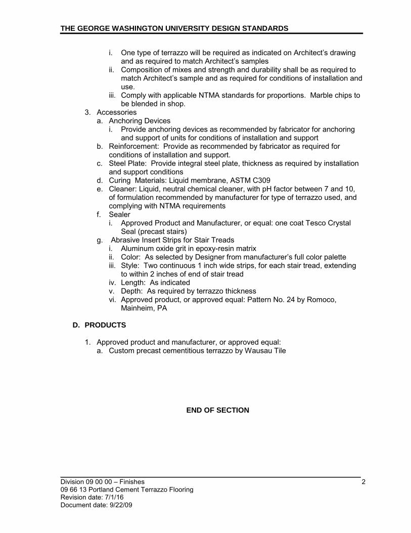
THE GEORGE WASHINGTON UNIVERSITY DESIGN STANDARDS
_________________________________________________________________________ Division 09 00 00 – Finishes 2 09 66 13 Portland Cement Terrazzo Flooring Revision date: 7/1/16 Document date: 9/22/09
i. One type of terrazzo will be required as indicated on Architect’s drawing and as required to match Architect’s samples
ii. Composition of mixes and strength and durability shall be as required to match Architect’s sample and as required for conditions of installation and use.
iii. Comply with applicable NTMA standards for proportions. Marble chips to be blended in shop.
3. Accessories a. Anchoring Devices
i. Provide anchoring devices as recommended by fabricator for anchoring and support of units for conditions of installation and support
b. Reinforcement: Provide as recommended by fabricator as required for conditions of installation and support.
c. Steel Plate: Provide integral steel plate, thickness as required by installation and support conditions
d. Curing Materials: Liquid membrane, ASTM C309 e. Cleaner: Liquid, neutral chemical cleaner, with pH factor between 7 and 10,
of formulation recommended by manufacturer for type of terrazzo used, and complying with NTMA requirements
f. Sealer i. Approved Product and Manufacturer, or equal: one coat Tesco Crystal
Seal (precast stairs) g. Abrasive Insert Strips for Stair Treads
i. Aluminum oxide grit in epoxy-resin matrix ii. Color: As selected by Designer from manufacturer’s full color palette iii. Style: Two continuous 1 inch wide strips, for each stair tread, extending
to within 2 inches of end of stair tread iv. Length: As indicated v. Depth: As required by terrazzo thickness vi. Approved product, or approved equal: Pattern No. 24 by Romoco,
Mainheim, PA
D. PRODUCTS 1. Approved product and manufacturer, or approved equal:
a. Custom precast cementitious terrazzo by Wausau Tile
END OF SECTION

_________________________________________________________________________
_________________________________________________________________________ Division 09 00 00 – Finishes 1 09 66 23 Epoxy Resin Terrazzo Flooring Revision date: 7/1/16 Document date: 9/22/09
THE GEORGE WASHINGTON UNIVERSITY DESIGN STANDARDS This document provides design standards only, and is not intended for use, in whole or in part, as a specification. Consultants referencing this information must always meet all applicable state and local building codes as well as all barrier free design requirements. Consultants must also refer to the entire set of Design Standards for additional information. Refer questions and comments regarding the content and use of this document to the George Washington University Project Manager.
09 66 23 EPOXY RESIN TERRAZZO FLOORING
A. SUMMARY
This section contains design standards for epoxy resin terrazzo flooring. Refer to space standards for additional information. 1. Reference Standards
a. Comply with applicable provisions and recommendations of National Terrazzo and Mosaic Association, Inc. (NTMA).
2. Description of Work a. Thinset epoxy terrazzo flooring b. Accessories c. Acceptable products and manufacturers
B. GENERAL
1. In order to meet LEED IEQ Credit 4.3 Low-Emitting Materials – Flooring
Systems, any site-applied adhesives, grouts, finishes, and sealers must meet FloorScore standards.
C. STANDARDS 1. Terrazzo Materials
a. Epoxy resins: to consist of 100% solids complying with performance requirements
b. Colorants: non-fading and factory dispersed c. Primer: 100% solids primer for epoxy resin terrazzo, as recommended by
system manufacturer d. Marble chips: natural, sound, and crushed without excessive flats or flakes,
size No. 1 and No. 2, complying with NTMA requirements e. May contain metal, plastic, glass, Mother of Pearl, stone chips and stone
dust. f. Polyester resins and polyacrylate resin systems are not acceptable. g. Grout: epoxy resin grout; cement grouts are not acceptable
2. Acceptable Products and Manufacturers a. Morricite Epoxy Terrazzo by Master Terrazzo Technologies, Hockessin, DE b. General Polymers Corporation, Cincinnati, OH c. TEC Inc./H.B. Fuller, Palatine, IL
3. Accessories a. Divider and control joint strips: white zinc alloy
i. Divider strips: Angle type

THE GEORGE WASHINGTON UNIVERSITY DESIGN STANDARDS
_________________________________________________________________________ Division 09 00 00 – Finishes 2 09 66 23 Epoxy Resin Terrazzo Flooring Revision date: 7/1/16 Document date: 9/22/09
ii. Control Joints: Double L-type angles, positioned back to back b. Anchoring Devices: Provide mechanical anchoring devices for divider and
control joint strips as required for secure attachment to substrate c. Anti-Fracture Membrane:
i. Self-curing liquid epoxy, 100% solids, as recommended by epoxy flooring manufacturer, to serve as anti-fracture or waterproofing membrane
ii. Provide with glass cloth reinforcement as recommended by terrazzo manufacturer for conditions of installation
d. Cleaner: i. Liquid, neutral chemical cleaner, with pH factor between 7 and 10 ii. Free from crystallizing salts and water-soluble alkaline salts;
biodegradable and phosphate-free iii. Formulation recommended by system manufacturer
4. Sealer a. Applied Initial Protectant:
i. Approved Product and Manufacturer or equal: 3M Scotchgard Stone Floor Protector, three coats
b. Long-Term Protectant: GW will install a final floor protection system to finish terrazzo floors. GW Project Manager shall coordinate the finishing work with the contractor’s schedule. i. Contractor shall protect openings adjacent to their work including doors,
stairwells and elevator pits, against migration of fluids.
END OF SECTION

_________________________________________________________________________
_________________________________________________________________________ Division 09 00 00 – Finishes 1 09 68 00 Carpet.doc Revision date: 7/1/18 Document date: 9/22/09
THE GEORGE WASHINGTON UNIVERSITY DESIGN STANDARDS This document provides design standards only, and is not intended for use, in whole or in part, as a specification. Consultants referencing this information must always meet all applicable state and local building codes as well as all barrier free design requirements. Consultants must also refer to the entire set of Design Standards for additional information. Refer questions and comments regarding the content and use of this document to the George Washington University Project Manager.
09 68 00 CARPET
A. SUMMARY
This section contains design standards for commercial carpet. Refer to space standards for additional information.
B. GENERAL
1. All carpet, whether broadloom or carpet tiles, must have the following properties:
a. Carpet shall be CRI Green Label Plus Certified. b. Carpet shall be entirely free of virgin PVC content. Recycled PVC content is
acceptable. c. Carpets eligible for manufacturer’s reclamation and recycling program at the
end of life cycle are preferred. Furthermore, products that can be separated as necessary and each composite material recycled back into the same material, rather than downcycling into a lower product, are preferred.
d. NSF-140-2007 Silver, Gold, or Platinum-Certified carpets are preferred. Higher levels are preferred where budget can accommodate.
e. Face fiber: 100% nylon 6 or nylon 6-6 f. Dying method: product must be 100% solution dyed g. Construction: tufted h. Appearance: In consideration of stain removal, solid colors shall not be
provided for other than Executive or Dean’s Offices. Color/design shall always be selected from manufacturer’s standard selection. Selections shall give strong preference for patterns that hide soiling well. For example, organic patterns are often superior to geometric patterns in this regard.
i. Warranties; all in effect for 15 years, minimum, unless otherwise noted: i. Warrant against any edge ravel, zippering, shrinking, and stretching ii. Warrant against delamination of backing from face iii. Warrant loss of no more than 10% of face fiber, by weight iv. Warrant against static electricity build-up in excess of 3.5 kv per AATCC
134 v. Tuft bind: average of 8 pounds per ASTM D 1335-67, “Tuft Bind of Pile
Floor Coverings” or for lifetime of product j. Density: per Table 1 below
i. Average Pile Yarn Density (APYD) as determined by D = 36 W / T where W = average pile yarn weight in ounces/ square yard; T = either the tuft height as determined by ASTM D-5823 or the average pile thickness computed in accordance with ASTM D-419 (section 10 or 11)
k. Carpet must meet at least one of the following criteria:

THE GEORGE WASHINGTON UNIVERSITY DESIGN STANDARDS
_________________________________________________________________________ Division 09 00 00 – Finishes 2 09 68 00 Carpet.doc Revision date: 7/1/18 Document date: 9/22/09
i. Carpet must be fully manufactured and at least 75% of its component materials, by weight, must be harvested/recovered/extracted within a 500 mile radius of the project site.
ii. Weighted recycled content for entire product assembly by weight as determined by formula below must be minimum 35% for carpet tile and minimum 30% for broadloom carpet:
(post-consumer recycled material weight
+ .5 x pre-consumer recycled material weight)
total product weight
For example, if a single carpet tile weighs 20 oz. and is composed of 2 oz. of post-consumer recycled material, 8 oz. of pre-consumer recycled material and 10 oz. from virgin sources, then the weighted recycled content of the carpet tile is as follows:
(2 oz. + .5 x 8 oz)
20 oz. = 30% weighted recycled content, which falls
short of the 35% threshold required for carpet tile
Note the following definitions established by the USGBC and applicable for projects at The George Washington University:
• Post-consumer material is waste material generated by households or by commercial, industrial and institutional facilities in their role as end-users of the product, which can no longer be used for its intended purpose.
• Pre-consumer material is material diverted from the waste stream during the manufacturing process. Excluded is reutilization of materials such as rework, regrind or scrap generated in a process and capable of being reclaimed within the same process that generated it.
Specifications must require - and Contractor submittals must provide - manufacturer’s documentation proving the recycled content threshold is met, as indicated in the calculation above. Statements claiming a certain percentage of either post-consumer or pre-consumer recycled content in the yarn or in the backing will not be acceptable, as the requirement is a percentage of the entire product by weight, which necessitates factoring in the percentage of product weight that each component offers.

THE GEORGE WASHINGTON UNIVERSITY DESIGN STANDARDS
_________________________________________________________________________ Division 09 00 00 – Finishes 3 09 68 00 Carpet.doc Revision date: 7/1/18 Document date: 9/22/09
C. TABLE 1: CARPET CLASS BY LOCATION The following table is provided for carpet class guidance where specified. There are occasions where an alternate surface material will be required in spaces noted below and this chart is not applicable in those cases.
Class I (Light-Moderate)
Class II (Heavy)
Class III (Extra Heavy)
• Density (APYD) > 4500 • Density (APYD) > 5500 • Density (APYD) > 6500
• private offices • board rooms • small computer rooms • library special collection
areas
• clerical areas • cashier windows • lounges • residential units • conference rooms • seminar rooms • art gallery • bookstores • TV/study rooms • athletic training rooms • classrooms • computer rooms • copier & A/V rooms • dressing rooms in
performance venues • stairs
• corridors • lobbies • dining rooms • recreation rooms • study lounges • jogging tracks • weight rooms • locker rooms • lounges • library reference and return
areas
D. EXTRA STOCK
1. Carpet Tile: Full-size units equal to 2 percent of amount installed for each style /
color in unopened boxes. 2. Broadloom: To be determined per project storage capacity; verify with Owner.
E. CARPET TILE
1. Product
a. Pile type: level loop or multi-level loop only; cut loop is unacceptable b. Minimum face weight
i. 16 oz. per sq. yd. c. Density as required by Table 1
2. Approved manufacturers or equal subject to compliance with requirements: a. InterfaceFlor b. The Mohawk Group (Bigelow or Lees) c. Shaw Industries (Shaw Contract or Patcraft)
3. Backing

THE GEORGE WASHINGTON UNIVERSITY DESIGN STANDARDS
_________________________________________________________________________ Division 09 00 00 – Finishes 4 09 68 00 Carpet.doc Revision date: 7/1/18 Document date: 9/22/09
a. Backing: synthetic b. Approved backing or equal subject to compliance with requirements (current
compliance to be confirmed by Consultant) or equal: i. Glasbac RE backing by InterfaceFlor ii. UltraSet RC backing by The Mohawk Group (Bigelow or Lees) iii. Ecoworx backing by Shaw
4. Adhesive a. Releasable, pressure-sensitive adhesive, cured properly and to
manufacturer’s recommendations before carpet is installed to allow for removal and to prevent permanent bond with carpet backing
b. Premium type recommended by carpet manufacturer for the specific carpet line/backing selected
c. Low/no-VOC and compliant with the current South Coast Air Quality Management District (SCAQMD) Rule #1168 or 50 g/L (less water), whichever is most restrictive
d. CRI Green Label Plus Certified
F. BROADLOOM CARPET 1. Product
a. Pile type: level loop or multi-level loop only; cut loop is unacceptable b. Minimum face weight
i. Class I: 24 oz. per sq. yd. ii. Class II: 26 oz. per sq. yd. iii. Class III: 28 oz. per sq. yd
c. Density as required by Table 1 d. Backing: performance
2. Approved manufacturers and backing or equal subject to compliance with requirements (current compliance with noted requirements herein to be confirmed by Consultant) a. Shaw Industries (Shaw Contract or Patcraft); backing: EcoWorx Performance
Broadloom or Ultraloc Pattern BL i. Approved equals by the following are also acceptable:
a.) Beaulieu Commercial (Bolyu line) b.) The Mohawk Group (Bigelow or Lees lines)
3. Adhesive a. Direct glue-down b. Premium type recommended by carpet manufacturer for the specific carpet
line selected c. Low/no-VOC and compliant with the current South Coast Air Quality
Management District (SCAQMD) Rule #1168 or 50 g/L (less water), whichever is most restrictive
d. CRI Green Label Plus Certified
G. INSTALLATION 1. Install in accordance with manufacturer’s instructions and recommendations.
END OF SECTION

_________________________________________________________________________
_________________________________________________________________________ Division 09 00 00 - Finishes 1 09 77 13 Stretched-Fabric Wall Systems Revision date: 7/1/12 Document date: 7/1/10
THE GEORGE WASHINGTON UNIVERSITY DESIGN STANDARDS This document provides design standards only, and is not intended for use, in whole or in part, as a specification. Consultants referencing this information must always meet all applicable state and local building codes as well as all barrier free design requirements. Consultants must also refer to the entire set of Design Standards for additional information. Refer questions and comments regarding the content and use of this document to the George Washington University Project Manager.
09 77 13 STRETCHED-FABRIC WALL SYSTEMS
A. SUMMARY
This section contains design standards for stretched fabric wall systems, trims, and accessories.
B. GENERAL
1. Residence Halls: Stretched-fabric wall systems shall not be utilized in residence
hall projects. Linoleum bulletin board products such as those by Forbo shall be utilized. Refer to 10 11 23 Bulletin Boards and Bulletin Board Cabinets for additional information.
2. Stretched fabric wall systems are preferred over direct-glue fabric panel systems since their installation does not make use of adhesives and sealants. This benefits indoor air quality due to the fact that there are no VOC’s added to the building from chemicals that are typically associated with the installation of wall coverings.
3. For environmental and health reasons, PVC-free fabric materials are preferred over products containing PVC.
4. Panel system components including face fabric, core material, and extrusions with a high degree of postconsumer recycled content are preferred.
5. Coordinate layout and installation of panel systems and attachment system components with other surrounding work in walls and ceilings, and with adjacent wood and/or gypsum board panels.
6. Fabrics shall comply with fire resistance rating requirements. 7. Provide stretched fabric systems fabricated with wood obtained from forests
certified by an FSC-accredited certified body.
C. EXTRA STOCK 1. Fabric: For each fabric, color and pattern installed, furnish length equal to 10
percent of amount installed, but no fewer than 10 yards. 2. Framing and Related Installation Items: Furnish manufacturer's full-length units
equal to 5 percent of amount installed, but no fewer than 5 units, including unopened adhesives.

THE GEORGE WASHINGTON UNIVERSITY DESIGN STANDARDS
_________________________________________________________________________ Division 09 00 00 - Finishes 2 09 77 13 Stretched-Fabric Wall Systems Revision date: 7/1/12 Document date: 7/1/10
D. STRETCHED FABRIC WALL SYSTEMS 1. Stretched Fabric Panel Systems:
a. Description: Perimeter framework with acoustical core, and field-stretched fabric covering mechanically fastened to framework without use of adhesives, nails, tacks, screws, or tapes.
b. Framework: i. Manufacturer’s standard rigid vinyl locking channels; UL-approved for fire-
retardancy. ii. Edge Profile: Square.
c. Tackable Core: Core material shall be tackable, impact-resistant, high density board. i. Mineral-fiberboard, with maximum flame-spread and smoke-developed
indexes of 15 and 5, respectively. ii. Thickness: 5/8” iii. Product and manufacturer: Equivalent to “Micore” by United States
Gypsum Company d. Finish: Fabric-wrapped e. Flame spread: ASTM E84 unadhered, 0-25 f. Noise-reduction coefficient (NRC range): ASTM C423, 0.85 g. Acceptable Products and Manufacturers:
i. Standard of quality is established by products manufactured by Novawall by Novawall Systems, Inc.
ii. Equivalent products by the following are acceptable: a.) Stretch Wall Products, Inc. b.) Whisper Walls
2. Fabric Facing Materials: a. The fabric shall meet performance requirements for a stretched fabric system
application and must be approved by the panel system manufacturer for systems compatibility.
b. The fabric shall be constructed with a plain weave from durable fibers. Fabrics with nylon or rayon content, fabrics with an open, loose weave, and fabrics that are too thick or thin are usually not well suited to stretched fabric panel applications.
c. The fabric shall have self-healing characteristics. d. Subject to compliance with requirements, provide fabric from one of the
following: i. Acceptable Fabric Manufacturers, or equal:
a.) Knoll Textiles b.) Carnegie c.) Maharam d.) Designtex
e. Fabric style and color shall be selected by Architect from manufacturer’s full color range, as indicated on Drawings and matching the samples approved by the Architect
f. Fabric Treatment: i. Fire Retardant Treatment: Provide manufacturer’s recommended
chemical treatment which does not discolor fabric, compatible with stain-repellant treatment, if used on fabric

THE GEORGE WASHINGTON UNIVERSITY DESIGN STANDARDS
_________________________________________________________________________ Division 09 00 00 - Finishes 3 09 77 13 Stretched-Fabric Wall Systems Revision date: 7/1/12 Document date: 7/1/10
ii. Stain Repellant Treatment: Provide manufacturer’s recommended chemical treatment which does not discolor fabric, compatible with fire retardant treatment.
iii. Fabric shall have single coat, upholstery grade acrylic backing when required for installation.
3. Panel Width and Height: Shall be as indicated on Drawings 4. Mid-Wall Configuration: Butt joint 5. Accessories
a. Provide concealed clips, fasteners, and items required for complete concealed attachment installation
E. INSTALLATION
1. Panels shall be installed in locations indicated with vertical surfaces
and edges plumb, top edges level and in alignment with other panels, faces flush, and accurately fitted to adjoining work at borders and at penetrations.
2. Installation of panels shall follow stretched fabric panel system manufacturer’s written instructions. Panels shall be securely anchored to supporting substrate.
3. Match and level fabric pattern and grain among adjacent panels.
END OF SECTION

_________________________________________________________________________
_________________________________________________________________________ Division 09 00 00 - Finishes 1 09 77 23 Fabric-Wrapped Panels Revision date: 7/1/12 Document date: 7/1/10
THE GEORGE WASHINGTON UNIVERSITY DESIGN STANDARDS This document provides design standards only, and is not intended for use, in whole or in part, as a specification. Consultants referencing this information must always meet all applicable state and local building codes as well as all barrier free design requirements. Consultants must also refer to the entire set of Design Standards for additional information. Refer questions and comments regarding the content and use of this document to the George Washington University Project Manager.
09 77 23 FABRIC-WRAPPED PANELS
A. SUMMARY
This section contains design standards for fabric wrapped panels, trims, and accessories.
B. GENERAL
1. Residence Halls: Fabric-wrapped panel systems shall not be utilized in residence
hall projects. Linoleum bulletin board products such as those by Forbo shall be utilized. Refer to 10 11 23 Bulletin Boards and Bulletin Board Cabinets for additional information.
2. Stretched fabric panel systems are preferred over direct glue fabric-wrapped panel systems since their installation does not make use of adhesives and sealants. This benefits indoor air quality due to the fact that there are no VOC’s added to the building from chemicals that are typically associated with installation of wall coverings.
3. For environmental and health reasons, PVC-free fabric materials are preferred over products containing PVC.
4. Panel system components including face fabric, core material and extrusions with a high degree of recycled content are preferred.
5. Installation adhesives shall have low VOC content per LEED Credit EQ 4.1 Low- Emitting Materials: Adhesives and Sealants. Adhesives shall comply with South Coast Air Quality Management District (SCAQMD) Rule #1168.
6. Manufacturer’s fiberboard shall have bonding agents that have low formaldehyde or contain no urea-formaldehyde resins per LEED Credit EQ 4.4 Low-Emitting Materials: Composite Wood and Agrifiber Products.
7. Coordinate layout and installation of tackable panels and attachment system components with other surrounding work in walls and ceilings, and with adjacent wood and gypsum board panels.
8. Fabrics shall comply with fire resistance rating requirements.
C. FABRIC WRAPPED PANELS 1. Fabric-Wrapped Panels:
a. Core Material: i. Mineral-Fiber Board:
a.) With maximum flame-spread and smoke-developed indexes of 15 and 5, respectively.
b.) Product: Subject to compliance with requirements, provide "Micore" by United States Gypsum Company

THE GEORGE WASHINGTON UNIVERSITY DESIGN STANDARDS
_________________________________________________________________________ Division 09 00 00 - Finishes 2 09 77 23 Fabric-Wrapped Panels Revision date: 7/1/12 Document date: 7/1/10
2. Fabric Facing Materials: a. Fabric must meet all performance requirements including fire rating and flame
retardancy, acoustical performance, durability, yarn content, fabric weight, and transparency. i. Acceptable Fabric Products and Manufacturers:
a.) Standard of quality is based on Xorel by Carnegie ii. Equivalent products by the following are acceptable:
a.) Designtex b.) Maharam
b. Fabric shall be provided from the same dye lot, color, and pattern as that selected by the Architect from Manufacturer's full range, as indicated on the Drawings and matching the samples approved by the Architect for use in the Work.
a. Fabric Treatment: i. Fire Retardant Treatment: Provide manufacturer’s recommended
chemical treatment which does not discolor fabric, compatible with stain-repellant treatment, if used on fabric
ii. Stain Repellant Treatment: Provide manufacturer’s recommended chemical treatment which does not discolor fabric, compatible with fire retardant treatment
iii. Fabric shall have single coat, upholstery grade acrylic backing when required for proper installation.
3. Panel Core: Provide the following core material interspersed with wood nailing strips a. Not less than 20-lb/cu. ft. (320-kg/cu. m) nominal density and 3/4-inch (19-
mm) nominal core thickness. b. Surface: Sanded
4. Panel Width and Height: Shall be as indicated on Drawings 5. Panel Edge and Frame: Extruded-aluminum or zinc-coated, rolled-steel shape
attached to the core a. Edge and Corner Detail: Square
6. Accessories a. Mounting Devices: Concealed on back of panel, recommended to support
weight of panel, and as follows: i. Metal "Z" Clips: Two-part panel clips, with one part of each clip
mechanically attached to back of panel and the other part to wall substrate, designed to allow for panel removal, unless otherwise indicated
D. INSTALLATION
1. Panels shall be installed in locations indicated with vertical surfaces
and edges plumb, top edges level and in alignment with other panels, faces flush, and accurately fitted to adjoining work at borders and at penetrations.
2. Comply with fabric-wrapped panel manufacturer's written instructions for installation of panels using type of concealed mounting accessories indicated or, if not indicated, as recommended by manufacturer. Panels shall be securely anchored to supporting substrate.
3. Match and level fabric pattern and grain among adjacent panels.

THE GEORGE WASHINGTON UNIVERSITY DESIGN STANDARDS
_________________________________________________________________________ Division 09 00 00 - Finishes 3 09 77 23 Fabric-Wrapped Panels Revision date: 7/1/12 Document date: 7/1/10
END OF SECTION

_________________________________________________________________________
_________________________________________________________________________ Division 09 00 00 – Finishes 09 91 23 Interior Painting
1
Revision date: 7/1/19 Document date: 9/22/2009
THE GEORGE WASHINGTON UNIVERSITY DESIGN STANDARDS This document provides design standards only, and is not intended for use, in whole or in part, as a specification. Consultants referencing this information must always meet all applicable state and local building codes as well as all barrier free design requirements. Consultants must also refer to the entire set of Design Standards for additional information. Refer questions and comments regarding the content and use of this document to the George Washington University Project Manager.
09 91 23 INTERIOR PAINTING
A. SUMMARY
This section contains general standards for paint and finish requirements. Refer to building type space standards for additional information.
B. GENERAL All interior paints and coatings applied at The George Washington University shall be zero VOC and shall meet or exceed Green Seal’s 1993 Environmental Standard for Paints and Coatings, GS-11.
C. INTERIOR PAINT STANDARDS
1. All painted surfaces shall receive one prime and two finish coats. 2. Primers shall be 100% acrylic latex. 3. In accordance with Facility Maintenance’s bulk pricing arrangements, all paints
used at The George Washington University shall be one of the following lines, no exceptions: a. ProMar 200 Zero VOC by Sherwin-Williams Company b. REVO by McCormick Paints/Total Advantage Zero VOC by McCormick
(Whole Building Application Only) c. EcoSpec WB by Benjamin Moore
4. Where white paint is specified, the designer shall specify one of the following options, no exceptions: a. Cool White: Benjamin Moore 857 “Sheep’s Wool”, or color match by
Sherwin Williams, or color match by McCormick Paints b. Neutral White: Sherwin Williams SW7006 “Extra White”(Pre-Mixed
Packaged Color), or color match by Benjamin Moore, or McCormick Paints color match “GW White”.
c. Warm White: Sherwin Williams SW7011 “Natural Choice”, or color match by McCormick Paints, or color match by Benjamin Moore
5. Where blue paint is specified, the color shall be: Sherwin-Williams SW6244 “Naval”, or match “GW Blue” by McCormick Paints, or color match by Benjamin Moore.
6. All other Pantone colors specified in the GW Identity Standards and Guidelines can be matched by Sherwin Williams or McCormick Paints. Consult with GW Paint Shop for further information.

THE GEORGE WASHINGTON UNIVERSITY DESIGN STANDARDS
_________________________________________________________________________ Division 09 00 00 – Finishes 09 91 23 Interior Painting
2
Revision date: 7/1/19 Document date: 9/22/2009
7. Accent Walls – Academic Buildings: a. One of the following accent colors shall be provided on the presentation or
teaching wall (the wall with the whiteboard or monitor) of a classroom: i. Sherwin Williams SW 6255 Morning Fog ii. Sherwin Williams SW 6374 Torchlight
8. Accent Walls – Residence Halls: a. Provide an accent color in common areas including corridors, lounges,
elevator lobbies and on the main floor. Anytime entire corridors are re-painted building-wide, accent walls shall be provided.
b. Only one accent color shall be provided throughout the entire building. One of the following Sherwin Williams colors shall be selected: i. SW 6255 Morning Fog ii. SW 6240 Windy Blue iii. SW 7602 Indigo Batik iv. SW 6242 Bracing Blue
9. For smaller renovation and retrofit projects where work occurs adjacent to existing spaces to remain, provide paint sheen to match existing surrounding area.
10. All paint colors and sheens shall be identified in the O&M manual with corresponding paint draw-down.
11. For renovation work, where existing paint on walls is oil-based, prepare and prime surface then apply latex paint. For doors, frames and trim, where existing paint is oil-based, use Sherwin Williams Pro Industrial Low VOC Waterbased Alkyd Urethane Enamel.

THE GEORGE WASHINGTON UNIVERSITY DESIGN STANDARDS
_________________________________________________________________________ Division 09 00 00 – Finishes 09 91 23 Interior Painting
3
Revision date: 7/1/19 Document date: 9/22/2009
Location-specific paint sheen and color requirements are as follows:
RESIDENCE HALL
Location Sheen Line/Color
Ceilings as follows:
• Housekeeping Closet • Kitchen • Mechanical / Electrical Room • Private Bathroom • Public Restroom • Stairway • Trash / Recycling Room
semi-gloss
Preferred: Sherwin-Williams Pro-Mar 200 Zero VOC, SW7006 “Extra-White” or McCormick REVO “GW White” or Color match by Benjamin Moore
• Apartment • Bedroom • Corridor, Hallway • All others
flat
Preferred: Sherwin-Williams Pro-Mar 200 Zero VOC, SW7006 “Extra-White” or McCormick REVO “GW White” or Benjamin Moore Eco-Spec color match.

THE GEORGE WASHINGTON UNIVERSITY DESIGN STANDARDS
_________________________________________________________________________ Division 09 00 00 – Finishes 09 91 23 Interior Painting
4
Revision date: 7/1/19 Document date: 9/22/2009
RESIDENCE HALL
Location Sheen Line/Color
Walls as follows:
• Housekeeping Closet • Kitchen • Mechanical / Electrical Room • Private Bathroom • Public Restroom • Stairway • Trash / Recycling Room
semi-gloss
Preferred: Sherwin-Williams Pro-Mar 200 Zero VOC, SW7667 “Zircon” or McCormick REVO color match or Benjamin Moore Eco-Spec color match.
• Apartment • Bedroom • Corridor, Hallway • Public Space • All others
eggshell
Paint line and color per design except where wall is white, provide: Preferred: Sherwin-Williams Pro-Mar 200 Zero VOC, SW7667 “Zircon” or McCormick color match or Benjamin Moore Eco-Spec color match.
Unit Entry Doors (if painted) & Door Frames semi-gloss
Sherwin Williams Pro-Mar 200 Zero VOC, “Argos” SW 7065
Unit Interior Doors and Door Frames semi-gloss
Sherwin-Williams Pro-Mar 200 Zero VOC, “Zircon” SW7667

THE GEORGE WASHINGTON UNIVERSITY DESIGN STANDARDS
_________________________________________________________________________ Division 09 00 00 – Finishes 09 91 23 Interior Painting
5
Revision date: 7/1/19 Document date: 9/22/2009
ACADEMIC/ADMINISTRATIVE
Location Sheen Line/Color
Ceilings as follows:
• Housekeeping Closet • Mechanical / Electrical Room • Pantry • Public Restroom • Stairway • Trash / Recycling Room
semi-gloss
Preferred: Sherwin-Williams Pro-Mar 200 Zero VOC, SW7006 “Extra-White” or McCormick REVO “GW White” or Benjamin Moore Eco-Spec color match.

THE GEORGE WASHINGTON UNIVERSITY DESIGN STANDARDS
_________________________________________________________________________ Division 09 00 00 – Finishes 09 91 23 Interior Painting
6
Revision date: 7/1/19 Document date: 9/22/2009
ACADEMIC/ADMINISTRATIVE
Location Sheen Line/Color
Ceilings as follows:
• Break-Out Room, Study Room, Lounge • Hallway, Corridor • Classroom, Computer Lab, Lecture Hall • Entry Vestibule • Lobby & Related Spaces • Mail, Files, Copy, Storage & Similar
Spaces • Office Suite Reception Area • Recycling & Waste Station, Built-In • All others
flat or semi-gloss
FLAT FINISHES: Preferred: Sherwin-Williams Pro-Mar 200 Zero VOC Ceiling Paint, Interior Latex Flat White #A27W05050 or Sherwin-Williams Pro-Mar 200 Zero VOC, SW7006 “Extra-White” or McCormick Premium Ceiling White #01040 or Benjamin Moore Eco-Spec color match. SEMI-GLOSS FINISHES: Preferred: Sherwin-Williams Pro-Mar 200 Zero VOC, SW7006 “Extra-White” or McCormick REVO “GW White” or Benjamin Moore Eco-Spec color match.

THE GEORGE WASHINGTON UNIVERSITY DESIGN STANDARDS
_________________________________________________________________________ Division 09 00 00 – Finishes 09 91 23 Interior Painting
7
Revision date: 7/1/19 Document date: 9/22/2009
ACADEMIC/ADMINISTRATIVE
Location Sheen Line/Color
Walls as follows:
• Housekeeping Closet • Mechanical / Electrical Room • Pantry • Public Restroom • Trash / Recycling Room
semi-gloss
Neutral, Warm or Cool white per section C.4
• Break-Out Room, Study Room, Lounge • Circulation (Hallway, Corridor, Stair) • Classroom, Computer Lab, Lecture Hall • Entry Vestibule • Lobby & Related Spaces • Mail, Files, Copy, Storage & Similar
Spaces • Recycling & Waste Station, Built-In
semi-gloss
Paint line and color per design except where wall is white, provide Neutral, Warm or Cool white per section C.4
• Office Suite Reception Area • Office • Conference Room
eggshell
Paint line and color per design except where wall is white, provide Neutral, Warm or Cool white per section C.4
Doors and door frames semi-gloss Paint line and color per design; contrast wall color
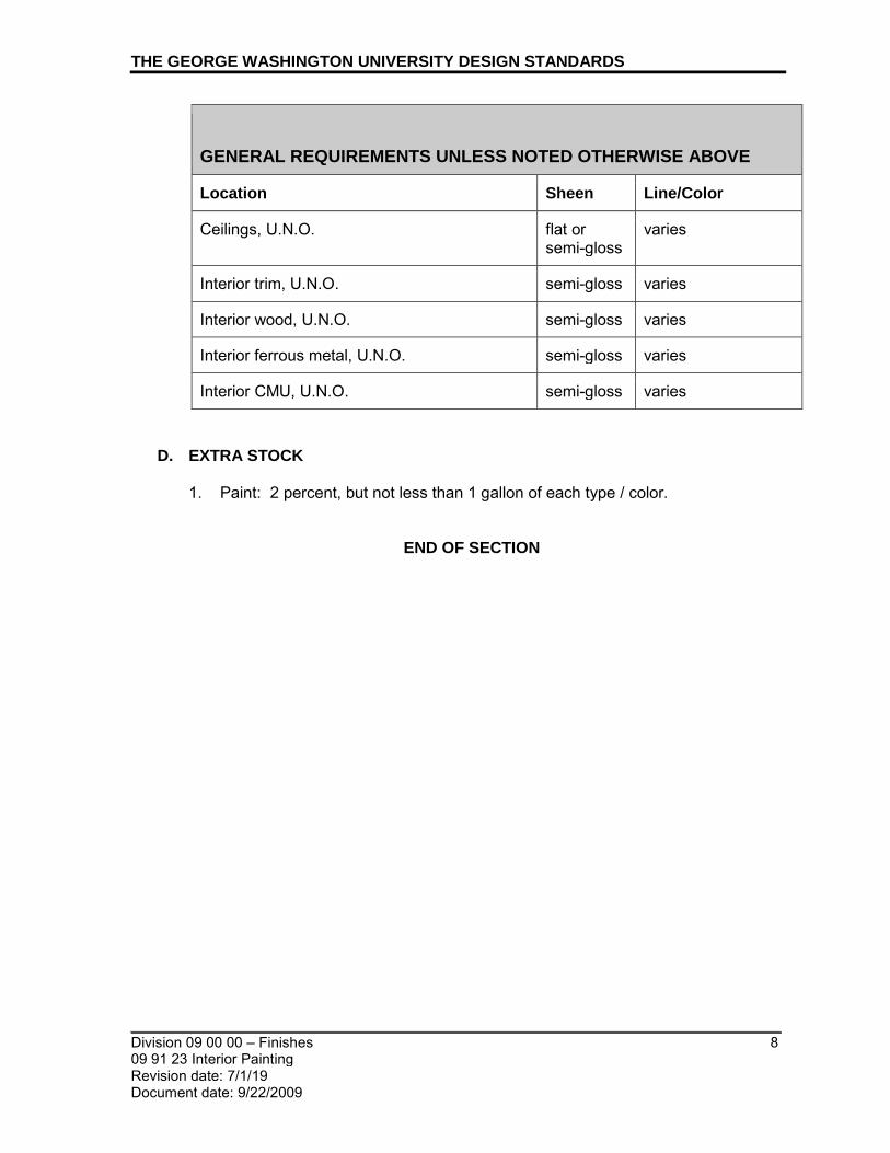
THE GEORGE WASHINGTON UNIVERSITY DESIGN STANDARDS
_________________________________________________________________________ Division 09 00 00 – Finishes 09 91 23 Interior Painting
8
Revision date: 7/1/19 Document date: 9/22/2009
GENERAL REQUIREMENTS UNLESS NOTED OTHERWISE ABOVE
Location Sheen Line/Color
Ceilings, U.N.O. flat or semi-gloss
varies
Interior trim, U.N.O. semi-gloss varies
Interior wood, U.N.O. semi-gloss varies
Interior ferrous metal, U.N.O. semi-gloss varies
Interior CMU, U.N.O. semi-gloss varies
D. EXTRA STOCK 1. Paint: 2 percent, but not less than 1 gallon of each type / color.
END OF SECTION

_________________________________________________________________________
_________________________________________________________________________ Division 09 00 00 – Finishes 1 09 96 56 Epoxy Coating Revision date: 1/1/18
Document date: 1/1/13
THE GEORGE WASHINGTON UNIVERSITY DESIGN STANDARDS This document provides design standards only, and is not intended for use, in whole or in part, as a specification. Consultants referencing this information must always meet all applicable state and local building codes as well as all barrier free design requirements. Consultants must also refer to the entire set of Design Standards for additional information. Refer questions and comments regarding the content and use of this document to the George Washington University Project Manager.
09 96 56 EPOXY COATING
A. SUMMARY
This section contains general standards for epoxy floor coatings for concrete surfaces. Include all applicable substrate testing, surface preparation and detail work. Refer to this section and related building type space standards for required locations/applications.
B. RELATED SECTIONS 1. 03 30 00 Cast-In-Place Concrete 2. 09 00 00 - Finishes
C. REFERENCE STANDARDS
1. American Society for Testing Materials - ASTM
a. ASTM E 84 Standard Test Method for Surface Burning Characteristics of Building Materials
b. ASTM D 4541 Standard Test Method for Pull-Off Strength of Coatings Using Portable Adhesion Testers
c. ASTM D 2047 Standard Test Method for Static Coefficient of Friction of Coated
d. Flooring Surface as Measured by the James Machine. e. ASTM G 53 Standard Practice for Operating Light-and Water Exposure
Apparatus (Fluorescent UV-Condensation Type) for Exposure of Nonmetallic Materials.
f. ASTM D 2240 Standard Test Method for Rubber Property-Durometer Hardness
g. ASTM D 3363 Standard Test Method for Film Hardness by Pencil Test h. ASTM D 4060 Standard Test Method for Abrasion Resistance of Organic
Coatings by the Taber Abrader i. ASTM D 523 Standard Test Method for Specular Gloss j. ASTM F 1869 Standard Test Method for Measuring Moisture Vapor Emission
Rate of Concrete Sub-floor Using Anhydrous Calcium Chloride k. ASTM D 1653 Standard Test Methods for Water Vapor Transmission of
Organic Coating Films l. ASTM C 309 Standard Specification for Membrane Forming Curing
Compounds m. ASTM C 1315 Standard Specification for Liquid Membrane Forming
Compounds having Special Properties for Curing and Sealing Concrete n. ASTM D 2369 Standard Test Method for Volatile Content of Coatings

THE GEORGE WASHINGTON UNIVERSITY DESIGN STANDARDS
_________________________________________________________________________ Division 09 00 00 - Finishes 2 09 96 56 Epoxy Coating Revision date: 1/1/18
Document date: 1/1/13
2. United States Green Building (USGBC) Council Leadership in Energy and Environmental Design (LEED) a. Building Design and Construction
3. United States Environmental Protection Agency (EPA) a. Method 24 – Determination of Volatile Matter Content of Surface Coatings
D. PRODUCT
1. Mechanical Rooms:
a. Basis of Design Product Product and Manufacturer: i. Stongard MR by Stonhard
2. Residence Hall Basements – Corridors, Laundry Rooms, Bike Rooms: a. Approved Product and Manufacturer, No Exceptions:
i. Stonclad GS/Tectop by Stonhard: Stonclad GS troweled epoxy mortar with Tectop EF epoxy resin flake broadcast flooring with textured surface for slip resistance a.) GS/Tectop: Stontec ERF is a nominal 2mm flooring system that
consists of a two-component epoxy primer, brightly colored quartz broadcast aggregate, and a three-component, self leveling epoxy base, brightly colored broadcast flakes, and a two-component, UV resistant, clear epoxy sealer
b. See the approved sample at the end of this section. c. The product must be installed by Stonhard, no exceptions.
E. INSTALLATION
1. The installer shall ensure that project conditions, including surface temperatures,
comply with all environmental requirements to ensure successful application of the product.
2. The installer shall apply the material in accordance with the manufacturer’s written instructions.
3. The epoxy shall be applied at the specified film thickness by method recommended by manufacturer.
4. The epoxy shall be allowed to dry thoroughly before re-coating per manufacturer’s instructions.
5. The same lot numbers shall be used throughout the project. 6. Finish coats shall be smooth, uniform in color and free of roller marks, laps, runs,
dry spray, overspray, skipped or missed areas. 7. Installation areas shall be kept free from traffic and other trades during the
applications procedure and cure time. 8. Finished surfaces of coating system shall be protected from damage during
construction.
F. QUALITY CONTROL 1. Architect shall visually inspect the finished surface for defects and shall approve
the finished surface via written acceptance.


_________________________________________________________________________
_________________________________________________________________________ Division 09 00 00 – Finishes 1 09 97 35 Dry Erase Coating Revision date: 1/1/15
Document date: 1/1/13
THE GEORGE WASHINGTON UNIVERSITY DESIGN STANDARDS This document provides design standards only, and is not intended for use, in whole or in part, as a specification. Consultants referencing this information must always meet all applicable state and local building codes as well as all barrier free design requirements. Consultants must also refer to the entire set of Design Standards for additional information. Refer questions and comments regarding the content and use of this document to the George Washington University Project Manager.
09 97 35 DRY ERASE COATING
A. SUMMARY
This section contains general standards for dry erase coating (whiteboard painted surfaces). Refer to related specification guidelines for additional information.
B. REFERENCES 1. GA-214, Recommended Levels of Gypsum Board Finish 2. ASTM C840, Standard Specification for Application and Finish of Gypsum Board
C. GENERAL
1. Product
a. General: 2-part, solvent-based, roller-applied, dry erase coating that enables any wall or smooth surface to be used as a writing surface
b. Color: White c. Coating must be applied over manufacturer’s base coat product exactly per
manufacturer’s instructions and specifications d. Low-VOC; Formaldehyde-free e. Environmental Certification: Greenguard Certified
2. Recommend that rooms utilizing dry erase paint have accent-colored walls to distinguish non-writable surfaces.
3. Basis of Design: a. New Construction, Major Renovations, and Unoccupied Spaces:
i. IdeaPaint PRO by IdeaPaint, Ashland, MA (national distributor is MDC, Elk Grove Village, IL)
b. Occupied Spaces: i. IdeaPaint Create (This is a low odor, low VOC, isocyanate-free formula
with a 10 year limited warranty vs. IdeaPaint PRO which has a limited lifetime warranty. The manufacturer still recommends proper ventilation of the space as is recommended when applying any traditional paint.)
4. Installation: a. GW Office of Health and Safety shall be notified prior to installation of
IdeaPaint products. b. Surface Preparation: Level 5 finish drywall (ASTM C840, GA-214) substrate
must be provided. c. IdeaPaint PRO:
i. Paint shall be applied and cured exactly per manufacturer’s specifications to ensure best results. 7 days minimum is required for curing prior to commencing writing and erasing activity.

THE GEORGE WASHINGTON UNIVERSITY DESIGN STANDARDS
_________________________________________________________________________ Division 09 00 00 - Finishes 2 09 97 35 Dry Erase Coating Revision date: 1/1/15
Document date: 1/1/13
ii. Application Rate: Maximum 50 square feet per quart iii. 2 coats of IdeaPaint PRO shall be applied over the prepped and primed
surface using the foam roller included in the manufacturer’s kit. iv. Ventilation: During product installation, ensure that the space is properly
ventilated per manufacturer’s instructions and specifications. IdeaPaint Pro has a much stronger odor than regular latex paint. Allow 24 hours for odor to dissipate – where possible, open windows, doors and set HVAC system to 100% fresh air exhaust to ventilate the area and prevent permeating odor. Ensure that occupants are not present.
v. Paint requires 7 days initial cure time before writing and erasing activity can commence. Writing and erasing performance will continue to improve as the IdeaPaint surface ages.
vi. The installer shall be an IdeaPaint-Approved Installer.
D. USAGE, CARE AND MAINTENANCE (for GW community) Refer to the manufacturer’s instructions and specifications for the complete set of requirements. This section will continue to be updated to reflect ‘lessons learned’ as whiteboard paint surfaces are used and maintained. 1. Writing/Markers:
a. For best performance of IdeaPaint surfaces use EXPO BOLD dry erase markers. Do not use “low odor” dry erase markers as they cause performance issues on the surface and may cause ghosting depending on the brand and color used. Replace markers frequently to prevent dried frayed tips from being used on the surface.
b. NEVER use permanent markers on the IdeaPaint surface. If a permanent marker is accidently used, try to remove by writing over the permanent marks with an EXPO BOLD dry erase marker – trace over the mark several times. Then, erase with a microfiber towel.
2. Erasing a. Professors and students should erase classwork at the end of each class
session using microfiber cloths provided. Traditional blackboard/whiteboard dry erasers should not be used. Heavily used microfiber cloths must be placed in containers marker “USED” for laundering/re-use.
3. Cleaning a. Daily: Housekeeping will perform a daily cleaning of surfaces with the use of
a dry microfiber cloth. b. Weekly: For a more thorough cleaning of surfaces, Housekeeping will use a
microfiber cloth dampened with plain water or Expo White Board Care (liquid spray cleaner) or IdeaPaint spray cleaner. Housekeeping will retrieve used microfiber cloths for laundering. Academic Support will supply clean microfiber cloths.
c. Never use harsh solvents or cleaners including electrostatically-charged water/ionized water/blue cleaning and the following: i. Windex ii. Scotch-Brite or other abrasive pads iii. Comet, Soft Scrub, or other abrasive cleaners iv. Brillo pads v. Steel wool

THE GEORGE WASHINGTON UNIVERSITY DESIGN STANDARDS
_________________________________________________________________________ Division 09 00 00 - Finishes 3 09 97 35 Dry Erase Coating Revision date: 1/1/15
Document date: 1/1/13
Repeated use of these products will destroy IdeaPaint’s dry erase performance!
4. A caddy or container will be installed at each surface containing the correct markers and microfiber cloths. In addition, a labelled box will be provided for the collection of used cloths that will be laundered and returned to the academic points of contact for room distribution.
E. PROPOSED SIGNAGE (for GW community; This section will continue to be updated
to reflect ‘lessons learned’ as whiteboard paint surfaces are used and maintained) The following signage shall be installed in classrooms, conference rooms, etc on the IdeaPaint surface or directly adjacent to the surface:
END OF SECTION
1. Use EXPO BOLD – or- IdeaPaint WRITE dry erase markers ONLY (NO “Low Odor” marker)
2. Erase with the microfiber cloth in the classroom supplied by GW.
3. Contact [name/phone] with any questions.

_________________________________________________________________________
_________________________________________________________________________ Division 10 00 00 – Specialties 1 10 11 16 Visual Display Surfaces Revision date: 7/1/16 Document date: 9/22/09
THE GEORGE WASHINGTON UNIVERSITY DESIGN STANDARDS This document provides design standards only, and is not intended for use, in whole or in part, as a specification. Consultants referencing this information must always meet all applicable state and local building codes as well as all barrier free design requirements. Consultants must also refer to the entire set of Design Standards for additional information. Refer questions and comments regarding the content and use of this document to the George Washington University Project Manager.
10 11 16 VISUAL DISPLAY SURFACES A. SUMMARY
This section contains general standards for markerboard assemblies. Refer to Academic Building space standards and Academic Technologies standards, “Classroom Design Specifications” for additional information regarding markerboards.
B. GENERAL
1. Location shall be as per program requirements and approved by Academic
Technologies. 2. Boards shall be a fixed style or a vertical or horizontal sliding style where
required by program and approved by Academic Technologies. 3. Boards shall be mounted at 3’-0” AFF to the bottom of each board.
C. FIXED MARKERBOARD ASSEMBLIES – PORCELAIN STEEL 1. Porcelain Steel Markerboard Assembly: Provide balanced, high- pressure,
factory-laminated porcelain enamel markerboard assembly of 3-ply construction consisting of face sheet, core material, and backing with aluminum trim a. Materials: Porcelain-Enamel Face Sheet shall be manufacturer's standard
steel sheet with porcelain enamel coating fused to steel; uncoated thickness indicated. Steel alloy shall be suitable for application of architectural porcelain enamel employing continuous coil process, properly pre-cleaned and treated. i. Gauge: As recommended by manufacturer but not less than 24 gage ii. Writing Surface Face Sheet: Writing surface finish shall be manufactured
in accordance with Porcelain Enamel Institute’s specifications: a.) Shall be enameling grade cold-rolled steel from a minimum of 30
percent post-consumer and post-industrial waste b.) Enameling grade steel shall be coated with LCS-II Porcelain Enamel
by Claridge Products and Equipment, or equal, subject to compliance with requirements
a) 3-coat enameling process shall consist of a bottom ground coat, top ground coat and top cover (color) coat
c.) Top Finish: Low reflective/low-gloss; dry-erase markers shall wipe clean with dry cloth or standard eraser, and finish shall be allow the markerboard to be used as a projection screen

THE GEORGE WASHINGTON UNIVERSITY DESIGN STANDARDS
_________________________________________________________________________ Division 10 00 00 – Specialties 2 10 11 16 Visual Display Surfaces Revision date: 7/1/16 Document date: 9/22/09
iii. Firing Temperature: Enamel shall be fired at the lowest possible temperatures to reduce steel and porcelain stresses and achieve superior enamel and hardness
iv. Color: White v. Writing Surface Core: Provide the manufacturer's standard 7/16 inch thick
medium density fiberboard (MDF) or 7/16 inch thick Duracore core material complying with the requirements of ANSI; core composition shall maximize the use of post-industrial waste, reclaimed, recycled fiber and/or post-consumer fiber
vi. Writing Surface Backing: 0.015” thick Aluminum sheet b. Panel Size: Architect shall specify writing surface panel length and height per
program and GW Academic Technologies requirements c. Aluminum Trim: Trim shall be 6063 alloy grade aluminum with T5 tempering
in accordance with ASTM B221, and shall have 201-R1 satin anodize finish. d. Accessories:
i. Marker Tray ii. Map Rail
e. Basis of Design Product: i. 75 LCS-II Low Gloss White by Claridge, Inc. ii. Or equal by one of the following manufacturers, subject to GW approval:
a.) Egan Visual, Inc. b.) Moore, Inc/Best-Rite/Balt
f. Mounting i. Marker boards should be mounted at 3’-0” AFF to the bottom of the
board. ii. Marker boards should have no less than 3’-0” vertical sections for writing
surfaces. g. Location in classrooms
i. Marker board location shall be as per the program requirements and approved by Academic Technologies.
D. FIXED MARKERBOARD ASSEMBLIES – GLASS
1. Glass Markerboard Assembly Description: Provide tempered, glass, dry-erase
marker board with 15 year warranty. Glass surface shall be resistant to stains, ghosting, scratches or dents and have a magnetic quality allows secure hanging of papers from glass surface with high power magnets.
a. Board design shall be frameless
b. White-colored, non-absorbent glass
c. Basis of Design Product: i. Infinity Glass Marker Boards by Quartet ii. Or equal by one of the following manufacturers, subject to compliance
with requirements: a.) Egan Visual, Inc. b.) Nuvacor

THE GEORGE WASHINGTON UNIVERSITY DESIGN STANDARDS
_________________________________________________________________________ Division 10 00 00 – Specialties 3 10 11 16 Visual Display Surfaces Revision date: 7/1/16 Document date: 9/22/09
E. SLIDING MARKERBOARD ASSEMBLIES
1. Horizontal Sliding Panels: Where required by program, provide horizontal sliding
markerboards including fixed back panel. Panels shall be manually-operated. Each sliding panel shall be equipped with manufacturer's standard horizontal sliding hardware consisting of overhead extruded aluminum track with nylon ball bearing rollers and channel shaped bottom guides. Hardware shall be designed and fabricated to produce smooth and easy operation without rattles.
2. Vertical Sliding Panels: Where required by program, provide vertical sliding markerboards including fixed back panel. Panels shall be manually-operated. Units and housing shall have standard components of the size, thickness, and design required to provide sufficient strength for support of panels independently of support from walls. Each sliding panel shall be equipped with manufacturer’s standard vertical sliding hardware designed and fabricated to produce smooth and easy operation without rattles.
F. MARKERBOARD ACCESSORIES 1. Aluminum Frames and Trim: Fabricated from not less than 0.062-inch thick, of
size and shape indicated a. Factory-Applied Trim: Manufacturer's standard b. Clear, anodized satin finish
2. Marker Tray: Manufacturer's standard, cantilever arm type, continuous. a. Box Type: Extruded aluminum with slanted front, grooved tray, and cast-
aluminum end closures. b. Clear, anodized satin finish c. Provide one box, 4 colors minimum, of liquid felt tip markers for each
individual markerboard installed 3. Display Rail:
a. Provide 2” extruded satin anodized aluminum, continuous display rail, with tackable cork inset strip
a. End Stops: Locate at each end of display rail. b. Display Hooks: Provide two map hooks for every 48 inches of display rail or
fraction thereof.
END OF SECTION

_________________________________________________________________________
_________________________________________________________________________ Division 10 00 00 – Specialties 1 10 11 23 Bulletin Boards and Bulletin Board Cabinets Revision date: 1/1/20 Document date: 9/22/09
THE GEORGE WASHINGTON UNIVERSITY DESIGN STANDARDS This document provides design standards only, and is not intended for use, in whole or in part, as a specification. Consultants referencing this information must always meet all applicable state and local building codes as well as all barrier free design requirements. Consultants must also refer to the entire set of Design Standards for additional information. Refer questions and comments regarding the content and use of this document to the George Washington University Project Manager.
10 11 23 BULLETIN BOARDS AND BULLETIN BOARD CABINETS
A. SUMMARY
This section contains general standards for bulletin boards and bulletin board cabinets. Refer to building type space standards for additional information. In residence halls, one bulletin board shall be provided across from the elevator on every floor. In all other building types, coordinate locations with Owner. Refer to space standards for additional information.
B. PRODUCTS
BULLETIN BOARDS 1. Residence Halls,
a. Approved products, or approved equal: i. Foam Bulletin Board by Quartet Prestige, Aluminum Frame, 4’X3’,
Product # B344A ii. Bulletin Board by Forbo Linoleum, Inc., Hazelton, PA
BULLETIN BOARD CABINETS 1. Description: Bulletin board cabinet with glass door 2. Door: 3/16” tempered glass door with continuous piano-type hinge; Flat key
tumbler lock 3. Dimensions: 24”w x 36”h X 1 ¾” deep (including trim and housing) 4. Back panel material: Claridge Cork 5. Cork Color: to match surrounding interior design scheme 6. Perimeter Trim: 1'' x 3'' hollow tube aluminum with satin anodized finish 7. Hanging Device: Z-Bar Hangers 8. Approved product and manufacturer, or approved equal:
a. Revere Series Bulletin Board Cabinet, Model 3520B by Claridge, Inc.
C. INSTALLATION 1. Bulletin Boards:
a. Installation method shall be such that the full depth of tackable material, whether the product alone, or it with a backing, allows for full-depth embedment of standard thumbtacks.
b. Frame, where required: extruded, clear anodized aluminum 2. Bulletin Board Cabinets:
a. Bulletin board cabinets shall be installed in drywall only.

THE GEORGE WASHINGTON UNIVERSITY DESIGN STANDARDS
_________________________________________________________________________ Division 10 00 00 – Specialties 2 10 11 23 Bulletin Boards and Bulletin Board Cabinets Revision date: 1/1/20 Document date: 9/22/09
b. Install cabinets in locations and mounting heights as indicated and in accordance with manufacturer's instructions, keeping assembly straight, plumb, and level.
END OF SECTION

_________________________________________________________________________
_________________________________________________________________________ Division 10 00 00 – Specialties 1 10 13 00 Directories Revision date: 1/1/12 Document date: 7/1/10
THE GEORGE WASHINGTON UNIVERSITY DESIGN STANDARDS This document provides design standards only, and is not intended for use, in whole or in part, as a specification. Consultants referencing this information must always meet all applicable state and local building codes as well as all barrier free design requirements. Consultants must also refer to the entire set of Design Standards for additional information. Refer questions and comments regarding the content and use of this document to the George Washington University Project Manager.
10 13 00 DIRECTORIES
A. SUMMARY
This section contains general standards for illuminated and non-illuminated directories. Refer to building type space standards for additional information.
B. GENERAL
1. Copy requirements shall be determined by GW. 2. Directory locations shall be approved by GW.
C. PRODUCTS
1. Illuminated Directories: a. General: Provide manufacturer’s standard assembly consisting of perimeter
frame, back, removable name strips, and frameless openable transparent cover, with concealed fluorescent illumination of name strips.
b. Frame: Extruded aluminum, depth as indicated with reinforced corners, flor fully recessed mounting
c. Cover: i. Frameless ii. Provide with concealed hinges and door latching mechanism
d. Header Panel: 4” high with text as indicated on Drawings e. Side panels: Provide side panel on both sides of directory with building name
on one side and building map on the other side, as required f. Size and Format: Custom, as indicated on Drawings g. Directory Format:
i. Black nylon carriers support and retain film negative graphic strips. Seal carriers to prevent light leakage
ii. Film carriers are retained by aluminum frame, which also supports translucent white acrylic diffuser panels in front of fluorescent lamps
h. Directory Name Strips: i. Provide ship-lapped glow-through graphic strips, 3/8” X length required
for size and format of directory ii. Strips interlock to prevent light leakage iii. Number or columns and strips to be determined by GW
i. Type style, size, position, color, and copy to be determined by GW j. Acceptable Product and Manufacturer: Equivalent to Visulite by Apco,
custom size as required k. Locations: First floor entrance lobbies, typical (Academic and Administrative
buildings)

THE GEORGE WASHINGTON UNIVERSITY DESIGN STANDARDS
_________________________________________________________________________ Division 10 00 00 – Specialties 2 10 13 00 Directories Revision date: 1/1/12 Document date: 7/1/10
2. Non-Illuminated Directories: a. General: Provide manufacturer’s standard assembly consisting of frame,
back, removable name strips, header panel, and hinged transparent cover b. Aluminum Perimeter Frame: Extruded aluminum with clear anodic finish.
i. Perimeter Frame Shape: Square. ii. Perimeter Frame Corners: Square.
c. Letterboard: Manufacturer's standard panel material, with grooves spaced at 1/4 inch (6 mm) o.c. to receive changeable letters. i. Color: As selected by Architect from full range of industry colors.
d. Letters: Molded plastic with tabs for engaging grooves in letterboard. Provide manufacturer's standard assortment of not less than 300 letters for each size, style, color, and case required; include letters, numbers, and characters. Package letters in compartmentalized carrying box. i. Height: 1/2 inch (13 mm) to top of capitals. ii. Style: As selected by Architect. iii. Color: As selected by Architect from full range of industry colors. iv. Case: Capitals and lowercase
e. Header Panel: Non-illuminated; with opaque, acrylic sheet panel set within overall perimeter frame; with matching frame that separates header panel from letterboard. i. Graphic Content and Style: Provide header panel copy that complies with
requirements indicated on Drawings for size, style, spacing, content, height, location, material, and colors.
ii. Color: As selected by Architect from full range of industry colors. iii. Width: As indicated on Drawings iv. Height: As indicated on Drawings
f. Acceptable Products and Manufacturer: Equivalent to Directory Series S560 Printed Panel Directory, as manufactured by InPro Signscape; or an equivalent product by one of the following: i. Claridge Products & Equipment, Inc. ii. Marsh Industries, Inc.
g. Locations: At each elevator lobby and main lobby of first floor (Academic and Administrative Buildings)
D. ACCESSORIES
1. Provide concealed fasteners and other accessories as recommended by
manufacturer and as required for proper and secure mounting to substrates.
E. INSTALLATION 1. For surface-mounted directories, secure both top and bottom of directories to
walls. 2. Mounting height shall be as indicated on Architect’s drawings.
END OF SECTION

_________________________________________________________________________
_________________________________________________________________________ Division 10 00 00 – Specialties 1 10 14 00 Signage Revision date: 4/1/20 Document date: 9/22/09
THE GEORGE WASHINGTON UNIVERSITY DESIGN STANDARDS This document provides design standards only, and is not intended for use, in whole or in part, as a specification. Consultants referencing this information must always meet all applicable state and local building codes as well as all barrier free design requirements. Consultants must also refer to the entire set of Design Standards for additional information. Refer questions and comments regarding the content and use of this document to the George Washington University Project Manager.
10 14 00 SIGNAGE
A. SUMMARY
This section contains general standards for exterior and interior signage. Refer to building type design standards, Room Numbering standards, and related specification guideline sections including 10 13 00 Directories and 27 42 00 Electronic Digital Signage Systems for additional information.
B. GENERAL
1. GW standard font for exterior and interior signage is Avenir. For additional
information regarding GW font types refer to GW Identity Standards and Guidelines. Contact Leah Rosen, Marketing and Creative Services with any questions.
2. Refer to GW Signage Manual at the end of this section for diagrams. 3. Refer to The Foggy Bottom Streetscape Plan for exterior signage requirements. 4. Signage proposed at the exterior of a historic or designated landmark building
within the Foggy Bottom Historic District will be reviewed by GW Campus Planning and referral made to the appropriate agencies.
5. Exterior and interior signage orders must be placed through GW’s Sign Shop which produces and installs all signage for projects. For exterior signage, an outside contractor is engaged to produce and install the pin-mounted letters. A Facilities Maintenance Work Request must be completed to start the process. For specialized, custom signage an outside vendor may need to be engaged for fabrication and installation.
6. Signage shall comply with ADA requirements. 7. All exterior signage, building and campus identifying elements shall comply with
campus master plans. Exterior signage for projects at the Foggy Bottom Campus must comply with the Foggy Bottom Campus Streetscape Plan.
8. Exterior building signage shall be vandal-proof and theft-resistant.
C. EXTERIOR SIGNAGE - INDIVIDUAL PIN-MOUNTED LETTERS
1. The following standards apply whether pin letters are for interior or exterior application.
i. Font: Avenir (per GW Identity Standards and Guidelines) ii. All capital letters iii. Letters individually mounted using concealed pins iv. Letter size: 6-12 inches high, depending on the space available v. Material: brushed stainless steel or finish to match existing building
material palette

THE GEORGE WASHINGTON UNIVERSITY DESIGN STANDARDS
_________________________________________________________________________ Division 10 00 00 – Specialties 2 10 14 00 Signage Revision date: 4/1/20 Document date: 9/22/09
vi. Mount with ¼ inch offset from face of wall.
D. INTERIOR ROOM SIGNAGE 1. Installation/Mounting Height:
a. Interior room signs shall be mounted at 60” from the finished floor to the baseline of Braille text.
2. Refer to the signage manual at the end of this section for detailed diagrams.
3. New Construction/Major Renovations
a. Academic, Administrative and Residential Common Spaces Typical Room Identification Sign (see diagram at the end of this section) i. Dimension: 6” H x 8 ½” W” ii. Wall or glass mount iii. Sign Plaque Material Options:
a.) ¼” P-95 Clear Acrylic Painted MP 04561 Snow Mist b.) ¼” thick Nuvacor VPS Porcelain White 35000; Matte
iv. Room Number/Braille: a.) Applied cut-out letter b.) 1/32” thick clear rowmark with adhesive back (all type and braille
raised 1/32”) c.) Paint to match Pantone 425U d.) Braille: Clear redundant raster bead e.) Typeface: Avenir Next LT Pro Demi
v. Room Name: a.) 1st surface screen printed b.) Paint to match Pantone 425U c.) Typeface: Avenir Next LT Pro Regular
b. Academic/Administrative Buildings – Private Office Identification Sign (see diagram at the end of this section) i. Dimension: 6” H x 8 ½” W” ii. Room ID with Direct Printed Insert iii. Wall or glass mount iv. Sign Plaque Material Options:
a.) ¼” P-95 Clear Acrylic Painted MP 04561 Snow Mist b.) ¼” thick Nuvacor VPS Porcelain White 35000; Matte
v. Room Number/Braille: a.) Applied cut-out letter b.) 1/32” thick clear rowmark with adhesive back (all type and braille
raised 1/32”) c.) Paint to match Pantone 425U d.) Braille: Clear redundant raster bead e.) Typeface: Avenir Next LT Pro Demi
vi. Insert Retainer: a.) Digitally printed copy directly 1st surface directly on substrate
vii. Milled Acrylic Lens a.) 1/8” thick clear matte acrylic lens with chamfered edges to be flush
with face insert retainer

THE GEORGE WASHINGTON UNIVERSITY DESIGN STANDARDS
_________________________________________________________________________ Division 10 00 00 – Specialties 3 10 14 00 Signage Revision date: 4/1/20 Document date: 9/22/09
c. Academic/Administrative Buildings – Cubicle/Workstation Identification Sign (see diagram) i. Dimension: 6” H x 8 ½” W” ii. Room ID with Paper Insert iii. Mount sign to J-hanger to attach to workstation panel iv. Sign Plaque Material Options:
a.) ¼” P-95 Clear Acrylic Painted MP 04561 Snow Mist b.) ¼” thick Nuvacor VPS Porcelain White 35000; Matte
v. Room Number/Braille: a.) Applied cut-out letter b.) 1/32” thick clear rowmark with adhesive back (all type and braille
raised 1/32”) c.) Paint to match Pantone 425U d.) Braille: Clear redundant raster bead e.) Typeface: Avenir Next LT Pro Demi
vi. Insert Retainer (Sliding Paper Insert for Name): a.) Mill for acrylic lens at 1st surface of sign plaque b.) Digitally printed copy on paper insert
vii. Milled Acrylic Lens a.) 1/8” thick clear matte acrylic lens with chamfered edges to be flush
with face insert retainer d. Residence Halls - Typical Residential Unit Signs
i. Dimension: 3”H x 6”W ii. Wall mount iii. Sign Plaque Material Options:
a.) ¼” P-95 Clear Acrylic Painted MP 04561 Snow Mist b.) ¼” thick Nuvacor VPS Porcelain White 35000; Matte
iv. Room Number/Braille: a.) Applied cut-out letter b.) 1/32” thick clear rowmark with adhesive back(all type and braille
raised 1/32”) c.) Paint to match Pantone 425U d.) Braille: Clear redundant raster bead e.) Typeface: Avenir Next LT Pro Demi
v. Room Name: a.) 1st surface screen printed b.) Paint to match Pantone 425U c.) Typeface: Avenir Next LT Pro Regular
4. Directional and Specialty Signage:
a. Directional Signage i. Located in areas such as elevator lobbies and corridors, which include
department names and arrows to assist building occupants find their destination
b. Informational Signage i. Located in areas such as elevator lobbies and corridors, which include
information for building occupants

THE GEORGE WASHINGTON UNIVERSITY DESIGN STANDARDS
_________________________________________________________________________ Division 10 00 00 – Specialties 4 10 14 00 Signage Revision date: 4/1/20 Document date: 9/22/09
c. Die-Cut Decal and Silk-Screen Signage i. Decal or silk-screen signage with an etched glass appearance is
preferred over true etched glasswork as decals can be changed more easily thus offering greater flexibility.
ii. Mounted on front or back of glass iii. Size varies iv. Custom design per program requirements
E. FIRE EVACUATION SIGNAGE BY OWNER (PROVIDED FOR INFORMATION
ONLY) 1. Fire evacuation signage is handled by GW Health and Emergency Management
Safety.
F. EMERGENCY RESPONSE SIGNAGE BY OWNER (PROVIDED FOR INFORMATION ONLY) 1. All laboratories and workshops across GW shall have Emergency Information
Signs describing the types of materials present within the space. This signage is also provides information that assists the emergency response team. Emergency Response Signage is managed by GW Health and Emergency Management Safety.
G. EMERGENCY RESPONSE SIGNAGE – AREA OF REFUGE 1. Refer to GW Emergency Response Handbook for detailed action steps to take in
a variety of situations - https://safety.gwu.edu/emergency-response-handbook. Consult with GW Health and Emergency Management Safety for additional information or specific inquiries.
2. Signage indicating locations areas of refuge shall be provided for all major academic and administrative buildings as well as residence halls. Signage shall be located in two locations: 1) outside of the exit stairwell door; and 2) inside the stairwell at the landing.
3. Directional signage indicating the location of the area of refuge shall be provided in the elevator lobby.
4. Size: 5”X5”
H. EXTERIOR ACCESSIBILITY SIGNAGE 1. Wheelchair-accessible parking signs
a. Description: Aluminum sheet minimum 0.080 inch thick, with silk-screened painted graphics as indicated on Drawings.
b. Graphics: i. Letters: Avenir (per GW Identity Standards and Guidelines) ii. Symbols: Universal graphic symbol for Handicapped. iii. Height of letters and graphics: Minimum 3 inches high. iv. Provide reflective blue graphics and border, on reflective white
background.

THE GEORGE WASHINGTON UNIVERSITY DESIGN STANDARDS
_________________________________________________________________________ Division 10 00 00 – Specialties 5 10 14 00 Signage Revision date: 4/1/20 Document date: 9/22/09
c. Sign size: 12 inches wide x 18 inches high. d. Mounting: Provide galvanized fasteners for mounting to concrete walls and
structure. e. Quantity: Provide one sign for each accessible parking space. f. Provide product and manufacturer complying with above and acceptable to
Architect.
I. INTERIOR SIGNAGE VENDORS 1. Takeform – Rob Ridgeway, [email protected], mobile - 410-707-6106 2. Signs by Tomorrow, Scott Goehrung, [email protected] 3. SMI Sign Systems, Inc – Marc Heyison, Office: 301-468-1132 (ext 119),
mobile: 240-481-9352; web: www.SMISigns.com 4. Gable - Jason Johnson, [email protected] 5. AGS - Adam Kozin, [email protected]
J. ACCESSORIES 1. Mounting Methods: Use fasteners or adhesives from materials that are not
corrosive to sign material and mounting surface. 2. Anchors and Inserts: Provide nonferrous-metal or hot-dip galvanized anchors
and inserts for exterior installations and elsewhere as required for corrosion resistance.
3. Provide concealed fasteners or adhesives as recommended by manufacturers and as required for permanent and secure mounting to substrates in each condition.

_________________________________________________________________________
_________________________________________________________________________ Division 10 00 00 – Specialties 1 10 21 13 Toilet Compartments Revision date: 7/1/17 Document date: 9/22/09
THE GEORGE WASHINGTON UNIVERSITY DESIGN STANDARDS This document provides design standards only, and is not intended for use, in whole or in part, as a specification. Consultants referencing this information must always meet all applicable state and local building codes as well as all barrier free design requirements. Consultants must also refer to the entire set of Design Standards for additional information. Refer questions and comments regarding the content and use of this document to the George Washington University Project Manager.
10 21 13 TOILET COMPARTMENTS
A. SUMMARY
This section contains general standards for toilet compartments. Refer to space standards and related sections for additional information. Work included in this section, but not necessarily limited to, includes: 1. Floor-mounted and overhead-braced solid resin toilet compartments 2. Urinal screens 3. Accessories
B. GENERAL
Requirements herein apply to toilet accessories found in both academic buildings and residence halls. Stainless steel accessories and trim throughout bathrooms shall be satin or brushed stainless steel, unless otherwise noted. Among others, these items may include, the following: towel bars, grab bars, folding shower seat supports, toilet tissue holders, metal shelves, medicine cabinets, mirror frames, robe hooks, shower rods, shower curtain hooks. If provided in stainless steel, cabinet hardware should match accessories.
C. TOILET PARTITIONS
1. Mounting: floor-mounted 2. Panels, doors, and pilasters:
a. Material: Panels should be solid high-density polyethylene (HDPE) or high-density polypropylene (HDPP) formed under pressure and heat into solid homogeneous sheets; non-laminated, non-absorbent. Note: A number of manufacturers’ standard HDPE lines contain 20%-70% post-industrial (pre-consumer) recycled HDPE. Maximizing the amount of post-consumer content is preferred where the budget allows. Scranton Products (parent company of Comtec, Santana, and Capitol Partitions) have a line of partitions made of 100% post-consumer recycled HDPE. 3Form (line: “100 Percent”) and Yemm & Hart (line: “Origins”) also make 100% post-consumer recycled HDPE partition panel material.
b. 1” thick, minimum c. Graffiti-resistant
3. Height: top of panel walls to be 69”, typical

THE GEORGE WASHINGTON UNIVERSITY DESIGN STANDARDS
_________________________________________________________________________ Division 10 00 00 – Specialties 2 10 21 13 Toilet Compartments Revision date: 7/1/17 Document date: 9/22/09
4. Panel color: to be selected from manufacturer’s full standard color range 5. Hardware
a. Manufacturer’s heavy-duty fastenings and fittings should be provided. b. Hinges: continuous self-closing stainless steel or aluminum c. Door latch: ADA-compliant, slide-type or lever latch and keeper. Thumbturn-
type latches are not acceptable. d. Each door to provide a combination coat hook/bumper. For coat
hook/bumper guideline specifications; refer to 10 28 00 Toilet and Bath Accessories, Section D.
e. Each compartment to have a utility shelf. For utility shelf guideline specifications, refer to 10 28 00 Toilet and Bath Accessories, Section D.
f. Door pulls should be on both faces of door for wheelchair-accessible compartments.
g. Finishes should be manufacturer’s standard cast alloy base metal (except as noted), US26 polished chrome finish.
6. Brackets, Fittings, and Fastenings: a. Brackets: continuous, extruded aluminum b. Shoes: stainless steel or aluminum c. Headrails: continuous, extruded aluminum d. Provide continuous, extruded aluminum channel on bottom of panels e. Exposed material finishes to match hardware
7. Doors a. Typical stall doors to be 24” wide, minimum. b. Barrier-free stall doors to be as required.
8. Approved manufacturers or approved equal: a. Bradley Corporation, Menomonee Falls, WI
i. Mills Partitions - Bradmar Partitions b. Scranton Products, Scranton, PA
i. Capitol Partitions, Inc., Columbia, MD ii. Santana Products/Hiny Hiders, Scranton, PA iii. Comtec Industries
c. Sanymetal, a Crane Plumbing Company, Somerset, KY
END OF SECTION

_________________________________________________________________________
_________________________________________________________________________ Division 10 00 00 – Specialties 1 10 28 00 Toilet and Bath Accessories Revision date: 1/1/17 Document date: 9/22/09
THE GEORGE WASHINGTON UNIVERSITY DESIGN STANDARDS This document provides design standards only, and is not intended for use, in whole or in part, as a specification. Consultants referencing this information must always meet all applicable state and local building codes as well as all barrier free design requirements. Consultants must also refer to the entire set of Design Standards for additional information. Refer questions and comments regarding the content and use of this document to the George Washington University Project Manager.
10 28 00 TOILET AND BATH ACCESSORIES
A. SUMMARY
This section contains general standards for toilet accessories. Refer to design standards and related sections for additional information.
B. GENERAL
Requirements herein apply to toilet accessories found in both academic buildings and residence halls. Stainless steel accessories and trim throughout bathrooms shall be satin or brushed stainless steel, unless otherwise noted. Among others, these items may include the following: towel bars, grab bars, folding shower seat supports, residential style toilet tissue holders, metal shelves, medicine cabinets, mirror frames, robe hooks, shower rods, shower curtain hooks. If provided in stainless steel, cabinet hardware should match accessories.
C. OWNER-PROVIDED, CONTRACTOR-INSTALLED ACCESSORIES FOR PUBLIC
RESTROOMS, PANTRIES AND LABORATORIES ONLY (Applicable to all building types except Residence Halls)
1. Owner-Provided, Contractor-Installed Accessories:
a. Wall-mounted soap/foam dispenser, Touchless i. Restroom: Provide one per every two sinks. Mount on wall between
lavatory mirrors. ii. Pantry: Provide one per sink. iii. Laboratory: Provide one per sink; verify with program.
b. Wall/partition-mounted disposable toilet seat cover dispenser i. Restroom: Provide one dispenser per toilet. Locate above the toilet,
except as may be otherwise required by barrier-free requirements. c. Touchless paper towel dispenser
i. Pantry: Provide one per pantry. ii. Laboratory: Provide one per sink; verify with program.
d. Wall/partition-mounted toilet tissue dispenser i. Restroom: Provide one per toilet.
e. Shower soap dispenser (Smith Center/Athletic Facilities) i. Shower: Provide one per shower unit
2. Architect shall confirm current accessories manufacturers and products with GW Facilities Services.
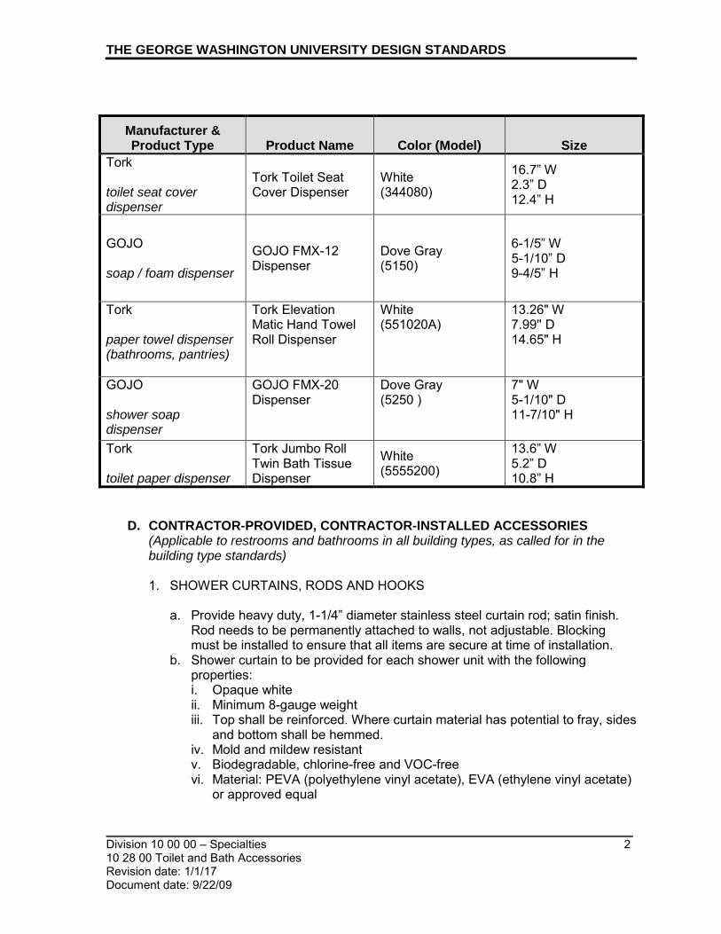
THE GEORGE WASHINGTON UNIVERSITY DESIGN STANDARDS
_________________________________________________________________________ Division 10 00 00 – Specialties 2 10 28 00 Toilet and Bath Accessories Revision date: 1/1/17 Document date: 9/22/09
Manufacturer & Product Type Product Name Color (Model) Size
Tork toilet seat cover dispenser
Tork Toilet Seat Cover Dispenser
White (344080)
16.7” W 2.3” D 12.4” H
GOJO soap / foam dispenser
GOJO FMX-12 Dispenser
Dove Gray (5150)
6-1/5” W 5-1/10” D 9-4/5” H
Tork paper towel dispenser (bathrooms, pantries)
Tork Elevation Matic Hand Towel Roll Dispenser
White (551020A)
13.26" W 7.99'' D 14.65" H
GOJO shower soap dispenser
GOJO FMX-20 Dispenser
Dove Gray (5250 )
7" W 5-1/10" D 11-7/10" H
Tork toilet paper dispenser
Tork Jumbo Roll Twin Bath Tissue Dispenser
White (5555200)
13.6” W 5.2” D 10.8” H
D. CONTRACTOR-PROVIDED, CONTRACTOR-INSTALLED ACCESSORIES (Applicable to restrooms and bathrooms in all building types, as called for in the building type standards) 1. SHOWER CURTAINS, RODS AND HOOKS
a. Provide heavy duty, 1-1/4” diameter stainless steel curtain rod; satin finish.
Rod needs to be permanently attached to walls, not adjustable. Blocking must be installed to ensure that all items are secure at time of installation.
b. Shower curtain to be provided for each shower unit with the following properties: i. Opaque white ii. Minimum 8-gauge weight iii. Top shall be reinforced. Where curtain material has potential to fray, sides
and bottom shall be hemmed. iv. Mold and mildew resistant v. Biodegradable, chlorine-free and VOC-free vi. Material: PEVA (polyethylene vinyl acetate), EVA (ethylene vinyl acetate)
or approved equal

THE GEORGE WASHINGTON UNIVERSITY DESIGN STANDARDS
_________________________________________________________________________ Division 10 00 00 – Specialties 3 10 28 00 Toilet and Bath Accessories Revision date: 1/1/17 Document date: 9/22/09
Material shall not be PVC; no exceptions. PVC has been linked to numerous health and environmental problems.
vii. Dimensions of shower curtain must provide full coverage for the entire shower. Shower curtains for typical shower enclosures shall be 72” high. Where shower opening is up to 48” wide, curtain shall be 6” wider than opening, minimum; where opening exceeds 48” wide, curtain shall be 12” wider then opening, minimum.
viii. Shower curtains for accessible enclosures (per ANSI/ADA) shall be sized to accommodate the longer shower opening, typically 78” – 80” high so that the bottom edge of the shower curtain touches the floor.
ix. Grommets shall be nonferrous metal c. A full set of stainless steel or alternate silver-colored, metallic, non-rusting,
wire curtain hooks shall be provided. Number to match number of shower curtain grommets. Hook size to suit shower curtain rod diameter and shower curtain grommets. Hook design to provide integrated closure; open hook style is not acceptable.
2. TOWEL BAR, HEAVY DUTY
a. 1” diameter bar b. Length: 18” c. Mounting: surface with wood blocking d. 18-gauge, type-304 stainless steel, satin finish e. Concealed mounting with snap flange f. Withstands 900-lb, minimum, downward pull when properly installed g. Model, or approved equal: Bobrick B-530 x 18
3. STAINLESS STEEL SHELF
a. Length: 24”, minimum b. Depth: 6” c. Mounting: surface with wood blocking d. Shelf: 18-gauge, type-304 stainless steel, satin finish e. Brackets: 16-gauge stainless steel, welded to shelf f. Shelf edges to be hemmed or rolled for safety g. Model, or approved equal: Bobrick B-296 x 24
4. MEDICINE CABINET – NON-ACCESSIBLE DWELLING UNITS
a. Mounting: Recessed b. Overall Size: 16” X 22” c. Rough Wall Opening: 14”X 18”H X3” D d. Cabinet construction: one-piece, white injection-molded polystyrene e. Polystyrene shelves (2, adjustable) f. Cabinet: Reversible for left-hand or right-hand door opening; full length piano
hinge g. Glass mirror shall have full surround stainless steel frame with tab, clip, or
screw closure h. Overall Depth: 3-3/4” i. Basis of Design, or equal subject to compliance with requirements:
a.) Bradley 9661

THE GEORGE WASHINGTON UNIVERSITY DESIGN STANDARDS
_________________________________________________________________________ Division 10 00 00 – Specialties 4 10 28 00 Toilet and Bath Accessories Revision date: 1/1/17 Document date: 9/22/09
5. MEDICINE CABINET – ACCESSIBLE DWELLING UNITS a. Mounting: Recessed
i. Medicine cabinet shall be mounted with the bottom edge of the reflecting surface at 40” above the finished floor to meet ADA requirements.
b. Overall Size: 16”W X 36”H X 4 ½”D c. Wall Opening/Rough-in Dimensions: 14”X 34”H X3 1/2” D d. Cabinet construction:
i. Formed and welded steel housing a.) 26 gauge steel construction with white, heat cured, acrylic paint finish
ii. Framed mirror door: a.) 3 mm thick float glass mirror door front with full, polished stainless
steel frame b.) 26 gauge steel door back with white, heat cured, acrylic paint finish
iii. Shelves: 26 gauge galvanized steel shelves with white, heat cured, enamel paint finish (2, adjustable)
iv. Cabinet: Reversible for left-hand or right-hand door swing v. Door Hinge: 32” full length piano (continuous) hinge vi. Magnetic catch in housing flange aligns to stainless steel striker plate on
the door (2) e. Basis of Design, or equal subject to compliance with requirements:
a.) Broan NuTone Styleline Medicine Cabinet a) Model # 840P34CH b) Description Styleline 1DR 16X36 SS8 WB/ST ST
6. MIRROR, RESIDENCE HALL UNIT BATHROOMS
a. Note: Provide only in exceptional circumstances and with Owner approval. Preference is for medicine cabinet to also serve as mirror above lavatory.
b. Frame: stainless steel with bright polished or satin finish to match medicine cabinet mirror frame
c. Concealed theft-resistant wall hangers d. Mounting: Surface e. Size: 24” wide x 36” high f. Model, or approved equal:
i. Bobrick B-165 2436 (no shelf) ii. Bobrick B-166 2436 (integral shelf)
7. LAVATORY MIRROR, PUBLIC RESTROOMS (ALL BUILDING TYPES)
a. Frame: stainless steel with bright polished finish b. Concealed theft-resistant wall hangers c. Size: 18” wide x 36” high, minimum. d. Mounting: Surface e. Model, or approved equal: Bobrick B-165-1836
8. ROBE/TOWEL HOOK
a. Robe/towel hook to be institutional grade, barrier-free, satin stainless steel unless otherwise noted.
b. Model, or approved equal: i. Double: Bobrick B-76727 ii. Single: Bobrick B-6717

THE GEORGE WASHINGTON UNIVERSITY DESIGN STANDARDS
_________________________________________________________________________ Division 10 00 00 – Specialties 5 10 28 00 Toilet and Bath Accessories Revision date: 1/1/17 Document date: 9/22/09
9. UTILITY SHELF a. Style: Folding. Shall self-return to upright, folded position when not in use b. Mounting: wall or partition c. Material: stainless steel or zinc with chrome plate finish d. Dimensions: minimum 14-1/2” long x 5-1/2” wide e. Model, or approved equal:
i. Bobrick B-287 ii. American Specialties 0698 iii. Bradley 790
10. SANITARY NAPKIN DISPOSAL
a. Receptacle with self-closing access door and 0.7 gallon leak-proof molded polyethylene receptacle liner (removable for servicing)
b. Door and Flange Material: Stainless steel with satin finish c. Basis of Design:
i. Partition-mounted (serves two toilet compartments): a.) Bobrick (Contura Series) Model B-4354
ii. Wall-mounted (recessed): Bobrick Model B-4353
11. COAT HOOK a. Provide one stainless steel or cast aluminum coat hook on inside face of
each toilet partition door. Provide with rubber bumper on in-swinging doors. Provide same or similar without rubber bumper for all out-swinging doors. i. Approved model, or equal: Bobrick B-212
12. GRAB BAR
a. Material: stainless steel, 18 gauge or better b. Finish: satin c. Diameter: 1-1/4” to 1-1/2” d. Projection from wall: 1-1/2” e. Mounting: surface with wood blocking f. Minimum force to withstand: 250 pounds g. Snap-on flanges for concealed attachment are required. Exposed mounting is
unacceptable. h. Model, or approved equal:
i. Bobrick B-5806 Series (1-1/4” diameter straight bar) ii. Bobrick B-6806 Series (1-1/2” diameter straight bar) iii. Bobrick B-68137 Series (1-1/2” diameter L bar; 36” x 54”)
13. FLOOR-STANDING OPEN-TOP WASTE RECEPTACLE
a. Coordinate receptacle selection with lavatory countertop design and information found in space standards (GW Design Standards) for public restrooms. i. The 13 gallon, 22”h receptacle shall be used for bathrooms in a
residential unit. Public restrooms shall be provided with taller receptacles (with or without lids) or placed under a counter with aperture.
b. Model, or approved equal, only where required clearance is available: i. American Specialties 0811 (13-gallon; 13” x 13” x 22”h) ii. American Specialties 0813 (19-gallon; 13” x 14” x 30”h)
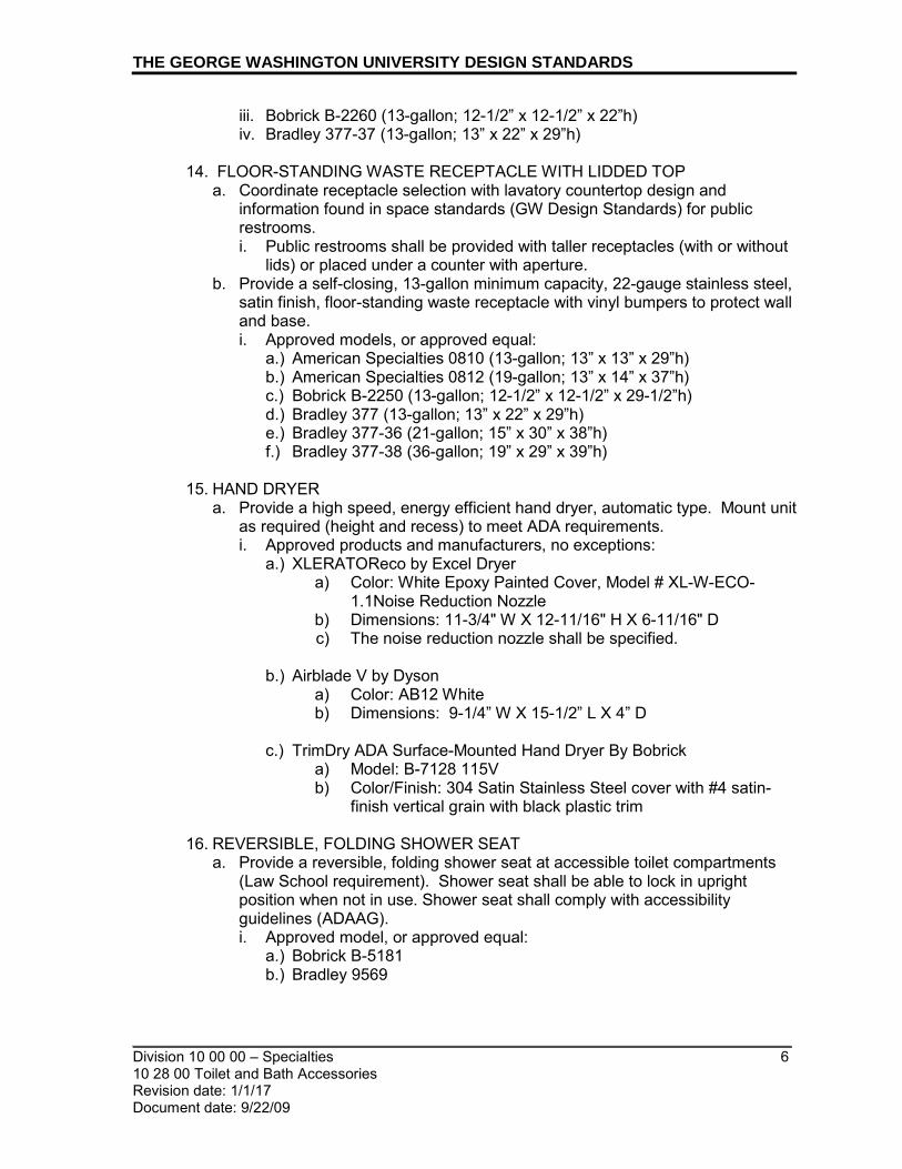
THE GEORGE WASHINGTON UNIVERSITY DESIGN STANDARDS
_________________________________________________________________________ Division 10 00 00 – Specialties 6 10 28 00 Toilet and Bath Accessories Revision date: 1/1/17 Document date: 9/22/09
iii. Bobrick B-2260 (13-gallon; 12-1/2” x 12-1/2” x 22”h) iv. Bradley 377-37 (13-gallon; 13” x 22” x 29”h)
14. FLOOR-STANDING WASTE RECEPTACLE WITH LIDDED TOP
a. Coordinate receptacle selection with lavatory countertop design and information found in space standards (GW Design Standards) for public restrooms. i. Public restrooms shall be provided with taller receptacles (with or without
lids) or placed under a counter with aperture. b. Provide a self-closing, 13-gallon minimum capacity, 22-gauge stainless steel,
satin finish, floor-standing waste receptacle with vinyl bumpers to protect wall and base. i. Approved models, or approved equal:
a.) American Specialties 0810 (13-gallon; 13” x 13” x 29”h) b.) American Specialties 0812 (19-gallon; 13” x 14” x 37”h) c.) Bobrick B-2250 (13-gallon; 12-1/2” x 12-1/2” x 29-1/2”h) d.) Bradley 377 (13-gallon; 13” x 22” x 29”h) e.) Bradley 377-36 (21-gallon; 15” x 30” x 38”h) f.) Bradley 377-38 (36-gallon; 19” x 29” x 39”h)
15. HAND DRYER
a. Provide a high speed, energy efficient hand dryer, automatic type. Mount unit as required (height and recess) to meet ADA requirements. i. Approved products and manufacturers, no exceptions:
a.) XLERATOReco by Excel Dryer a) Color: White Epoxy Painted Cover, Model # XL-W-ECO-
1.1Noise Reduction Nozzle b) Dimensions: 11-3/4" W X 12-11/16" H X 6-11/16" D c) The noise reduction nozzle shall be specified.
b.) Airblade V by Dyson
a) Color: AB12 White b) Dimensions: 9-1/4” W X 15-1/2” L X 4” D
c.) TrimDry ADA Surface-Mounted Hand Dryer By Bobrick
a) Model: B-7128 115V b) Color/Finish: 304 Satin Stainless Steel cover with #4 satin-
finish vertical grain with black plastic trim
16. REVERSIBLE, FOLDING SHOWER SEAT a. Provide a reversible, folding shower seat at accessible toilet compartments
(Law School requirement). Shower seat shall be able to lock in upright position when not in use. Shower seat shall comply with accessibility guidelines (ADAAG). i. Approved model, or approved equal:
a.) Bobrick B-5181 b.) Bradley 9569
THE GEORGE WASHINGTON UNIVERSITY DESIGN STANDARDS
_________________________________________________________________________ Division 10 00 00 – Specialties 7 10 28 00 Toilet and Bath Accessories Revision date: 1/1/17 Document date: 9/22/09
17. HAIR DRYER a. Provide a push button activated hair dryer outside of shower units in adjacent
locker room area. Mount hi-lo pair of units; lo mounting height shall meet ADA requirements. i. Approved model, no exceptions:
a.) Excel Dryer
18. TOILET PAPER DISPENSER – RESIDENCE HALLS a. Provide a stainless steel or chrome, single roll, open loop residential style
toilet paper holder for each toilet. i. Approved model, or approved equal:
a.) Bobrick B-685/B685-7 or B-7685 b.) Bradley 5084 c.) Bradley 508, 508-32
E. INSTALLATION
1. Anchor securely to supporting construction, using concealed fasteners wherever
possible.
END OF SECTION

_________________________________________________________________________
_________________________________________________________________________ Division 10 00 00 – Specialties 1 10 44 00 Fire Protection Specialties Revision date: 1/1/13 Document date: 9/22/09
THE GEORGE WASHINGTON UNIVERSITY DESIGN STANDARDS This document provides design standards only, and is not intended for use, in whole or in part, as a specification. Consultants referencing this information must always meet all applicable state and local building codes as well as all barrier free design requirements. Consultants must also refer to the entire set of Design Standards for additional information. Refer questions and comments regarding the content and use of this document to the George Washington University Project Manager.
10 44 00 FIRE PROTECTION SPECIALTIES
A. SUMMARY
This section contains general standards for fire extinguishers and fire extinguisher cabinets.
B. STANDARDS 1. All Building Types
a. Fire extinguishers shall be provided as required by code. 2. Fire Extinguishers
a. Per the GW Office of Health and Safety, the University uses the following types of fire extinguishers: i. Carbon Dioxide (Class BC) ii. Multipurpose Dry Chemical (Class ABC) iii. Dry powder (Class D) iv. Halogenated v. Wet Chemical (Class K)
b. General Building Areas: i. Multipurpose Dry Chemical (Class ABC)
c. Museum/Art-Containing Spaces such as galleries and collection areas: i. Halogenated type extinguishers are required. ii. On floor levels that accommodate both artifact-containing and non-
artifact-containing spaces, consider providing both multipurpose dry chemical and halogenated extinguishers, either co-located in one larger cabinet or located in two separate cabinets, as space allows.
d. Building areas where cooking greases may cause fumes shall have Class K fire extinguishers.
e. The choice of specific fire extinguisher shall be at the specification of the Life Safety specialist employed by the Architect or Engineer. The choice is dependent on the special hazards of the area being served. Size/capacity of extinguisher shall be dependent upon potential use.
f. Fire extinguisher service contractor shall supply rated, appropriate extinguishers.
g. All fire extinguishers must be UL-listed and FM Global-approved. 3. Products must conform to the following standards:
a. National Fire Protection Association: NFPA 10 Standard for Portable Fire Extinguishers
b. Americans with Disabilities Act – ADA c. Uniform Federal Accessibility Standards – UFAS

THE GEORGE WASHINGTON UNIVERSITY DESIGN STANDARDS
_________________________________________________________________________ Division 10 00 00 – Specialties 2 10 44 00 Fire Protection Specialties Revision date: 1/1/13 Document date: 9/22/09
4. Fire Extinguisher Cabinets a. All cabinets should be fabricated to house one fire extinguisher. b. Units should be installed fully recessed with trim concealed by door. For
certain partition types, for example, on a block or cast in place wall, a surface mount cabinet may be necessary for budget reasons.
c. Cabinet door should be a single, flat panel with vertical vision panel that is factory glazed with clear glass.
d. Cabinet door hardware should be manufacturer’s standard with a surface mounted handle to match door finish, a roller latch, and any exposed hinges should match door finish.
e. Hinges should allow door a full 180° opening. f. Acceptable Products and Manufacturers, or equal:
i. Larsen’s Manufacturing Co. ii. J. L. Industries iii. Potter-Roemer, Inc.
END OF SECTION

_________________________________________________________________________
_________________________________________________________________________ Division 10 00 00 – Specialties 1 10 55 00 Postal Specialties Revision date: 1/1/14 Document date: 7/1/10
THE GEORGE WASHINGTON UNIVERSITY DESIGN STANDARDS This document provides design standards only, and is not intended for use, in whole or in part, as a specification. Consultants referencing this information must always meet all applicable state and local building codes as well as all barrier free design requirements. Consultants must also refer to the entire set of Design Standards for additional information. Refer questions and comments regarding the content and use of this document to the George Washington University Project Manager.
10 55 00 POSTAL SPECIALTIES A. SUMMARY
This section contains design standards for mailboxes and accessories for Residence Halls. Refer to space standards for additional information.
B. GENERAL
1. Mail for the entire GW campus is delivered and distributed from a central location
by GW Mail Services staff (The USPS does not provide delivery services). GW Mail Services requires the keys for all locks once mailboxes are installed.
2. Mail drop boxes shall not be provided for Residence Halls. Postal counter service is provided by GW Mail Services which is located on campus.
3. A misdirect mailbox shall be provided. Refer to the requirements provided below. 4. A key drop box shall be provided. Refer to the requirements provided below.
C. PRODUCTS
1. Mailboxes a. Description:
i. Front-loading, horizontally stacked modules consisting of multiple compartments with fixed, solid compartment backs; Entire assembly enclosed within a recessed wall box
ii. Material: Polycarbonate doors with 22-gauge galvanneal steel housing iii. Provide access to entire group of compartments for distributing incoming
mail from front of unit by unlocking master locks and swinging side-hinged master door open; Master door panel secured by two control locks
b. Compartments: i. Quantity and layout of compartments, as required to accommodate the
number of residents, as directed by Owner ii. Compartment Dimensions (interior): 3-5/8” min. W X 6.25”H X 15”D
c. Compartment Doors: i. Each compartment door shall have lock, tenant identification, and
concealed, full-length hinge on one side ii. Tenant Identification:
a.) Identification: Residential Unit Number indicated on face of compartment door within cardholder (name slot and clear cover)
b.) Provide blank cardholder identification tabs for printing a room number.
c.) Owner to coordinate numbering.

THE GEORGE WASHINGTON UNIVERSITY DESIGN STANDARDS
_________________________________________________________________________ Division 10 00 00 – Specialties 2 10 55 00 Postal Specialties Revision date: 1/1/14
Document date: 7/1/10
d. Compartment door locks: i. Three-digit, single-dial, combination lock with spring latch and automatic
throw-off. Each compartment shall have a different combination. ii. Approved Manufacturer and Product, or approved equal:
a.) Postal Products Unlimited, Inc., - Guardian Series Model N1023960 e. Approved Manufacturers and Products, or approved equal:
i. Postal Products Unlimited, Inc., - Guardian Module Model N1021244 ii. Salisbury Industries, Los Angeles, CA iii. Florence Manufacturing, A Gibraltar Industries Company
2. Misdirected Mail Box a. Description: Standard recess-mounted letter box with 11-1/2'' W x 3/4'' H mail
slot; Front door for private access for collection via key i. Box Material: Heavy duty sheet and extruded aluminum ii. Door Material: Heavy duty 1/4" thick aluminum
b. Overall Mail Box Dimensions: 15'' W x 19'' H x 7-1/2'' D c. Finish: Powder coated; Color: Aluminum d. Approved Manufacturer and Product, or approved equal:
i. Salsbury Industries – Model # 2245AP (Recess-mounted)
D. INSTALLATION 1. Mailboxes:
a. Mailboxes shall be installed with center of tenant-door lock cylinder not more than 67 inches above finished floor and bottom of lowest compartment not less than 28 inches above finished floor.
b. Arrange compartments in groups as indicated on Drawings. 2. Misdirected Mail Box:
a. Misdirected mail box shall be installed in accordance with box manufacturer’s directions, in location directed by Owner.
END OF SECTION

_________________________________________________________________________
_________________________________________________________________________ Division 11 10 00 – Vehicle and Pedestrian Equipment 1 11 13 19 Loading Dock Levelers Document date: 1/1/19
THE GEORGE WASHINGTON UNIVERSITY DESIGN STANDARDS This document provides design standards only, and is not intended for use, in whole or in part, as a specification. Consultants referencing this information must always meet all applicable state and local building codes as well as all barrier free design requirements. Consultants must also refer to the entire set of Design Standards for additional information. Refer questions and comments regarding the content and use of this document to the George Washington University Project Manager.
11 13 19 LOADING DOCK LEVELERS A. SUMMARY
This section contains design standards for loading dock levelers.
B. STANDARDS
1. Acceptable Manufacturers and Local Installers: a. Powerramp/DLM https://www.poweramp.com/
Local Installer - ODC Baltimore 3501 Century Ave Baltimore, Md 21227 Phone: (410) 636-6300 [email protected]
b. RiteHite https://www.ritehite.com/en/am Local Installer - Arbon Equipment Corporation - Northeast 7383 Washington Blvd., Suite 106 Elkridge MD 21075 United States Phone: (410) 796-5902 www.arbonequipment.com
c. Serco https://sercoentrematic.com/contact/
Local Rep - 1-800-933-4834
END OF SECTION
_________________________________________________________________________
_________________________________________________________________________ Division 11 00 00 – Equipment 1 11 24 23 Window Washing Systems Revision date: 1/1/12
Document date: 7/1/10
THE GEORGE WASHINGTON UNIVERSITY DESIGN STANDARDS This document provides design standards only, and is not intended for use, in whole or in part, as a specification. Consultants referencing this information must always meet all applicable state and local building codes as well as all barrier free design requirements. Consultants must also refer to the entire set of Design Standards for additional information. Refer questions and comments regarding the content and use of this document to the George Washington University Project Manager.
11 24 23 WINDOW WASHING SYSTEMS
A. SUMMARY
This section contains design standards for tieback anchor systems and davit assemblies to support exterior window washing.
B. GENERAL
1. GW predominantly utilizes roof and wall anchors for suspended access support
for exterior window washing. There are exceptions such as Ross Hall, the School of Business, and Marvin Center (atrium portion) which have davit systems. Architect shall select the window washing system as required to best suit the project’s roof design and configuration. Where special building features necessitate other access equipment, those systems shall be specified and provided according to applicable codes, regulatory requirements, and reference standards.
2. Summit Anchor currently provides anchor systems for many buildings on the Foggy Bottom campus. For additional information on current anchor systems at existing buildings, consult GW Facilities Services, Bill Hendrick.
3. Regulatory Requirements: Window washing system layout, roof plan, and details shall comply with all applicable requirements of OSHA, authorities having jurisdiction, and manufacturer: a. Safety anchor system shall comply with ANSI/IWCA I-14.1-2001 Window
Cleaning Safety Standard for fall arrest and suspended maintenance. b. Window washing system shall comply with all codes and reference standards
in addition to safety standards of authorities having jurisdiction including ANSI/ASME A120.1, OSHA standards and regulations including 1910.28, 1910.66, and US Dept. of Labor Memorandum to Regional Administrators for Descent Control Devices.
c. Electric components and wiring shall comply with standards of NEMA (National Electrical Manufacturers Association) and the National Electrical Safety Code, as applicable.
d. Welding shall comply with AWS D1.1 and shall be performed by welders qualified to work in jurisdiction where project is located.
e. Comply with AISC publications: i. Load and Resistance Factor Design for Structural Steel Buildings ii. Specifications for the Design of Cold-Formed Steel Structural Members
4. Interface With Other Systems: Installation of window washing system shall be coordinated with roofing manufacturer’s requirements.
5. System shall be installed by manufacturer, or by a firm approved by the manufacturer. Manufacturer is responsible for designing system including

THE GEORGE WASHINGTON UNIVERSITY DESIGN STANDARDS
_________________________________________________________________________ Division 11 00 00 – Equipment 2 11 24 23 Window Washing Systems Revision date: 1/1/12
Document date: 7/1/10
anchorage to structural system and necessary modifications to meet special requirements to maintain visual design concepts.
6. Approved Manufacturers and Products, or approved equal: a. Summit Anchor Company, Inc., Frederick, MD (Note: Summit Anchor
currently provides anchor systems for many buildings on the Foggy Bottom campus. For additional information regarding existing building renovation projects, consult GW Facilities Services, Bill Hendrick).
b. Spider Staging Co., Laurel, MD c. Pro-Bel Enterprises, Ltd., Ontario, Canada
C. TIEBACK ANCHOR SYSTEM 1. Design Requirements:
a. Safety anchor system design shall comply with current OSHA, ANSI, and local regulations pertaining to window cleaning and fall protection.
b. Anchor system shall provide independent fall arrest anchorages in addition to suspension line anchorages for each descent location as required by OSHA and ANSI requirements.
c. System shall be designed to be compatible with current window cleaning industry standard equipment such as rope descent systems, swing stages, and transportable suspension devices).
2. Structural Requirements: a. Anchorage shall be capable of sustaining a minimum ultimate load of 5,000
lbs., in any direction the load may be applied, without fracture or failure. b. Anchorage shall be capable of sustaining a minimum proof load of 2,500 lbs.,
in any direction the load may be applied, without permanent deformation or damage to anchorage.
c. Anchorages shall be designed with a minimum 1,250 lb. working load, in any direction the load may be applied.
d. Parapet or guardrails subject to direct loading by workers’ ropes, possibly cables, shall be designed to withstand such loading (typically 1,800 lbs) without damage to either the structure of the rigging component in contact with it.
3. Primary support and fall arrest anchors shall be located to coincide with areas on the façade of the building needing to be serviced. Consideration shall be given to the type of suspension equipment that will be used at the building and conditions such as workers’ reach, rigging methods, and roof edge conditions. Anchorages shall be unobstructed and located behind and in line with equipment or portion of building they are intended to service. Refer to manufacturer’s specifications for anchor spacing and layout.
4. Products: a. Provide wall- and/or roof-mounted anchor assembly as required. b. Description: Drop forged eye welded directly to pipe or to cap plate on steel
tube base i. Capable of withstanding 5,000 lbs. (2268kg) in any direction without
permanent deflection. ii. Anchor eye size: Not less than ¾ inch (20 mm) diameter material with 2
¼ in (60 mm) eye opening.

THE GEORGE WASHINGTON UNIVERSITY DESIGN STANDARDS
_________________________________________________________________________ Division 11 00 00 – Equipment 3 11 24 23 Window Washing Systems Revision date: 1/1/12
Document date: 7/1/10
iii. Anchor eye metals: a.) Forged, 1030 quenched and tempered per ASTM 576-90-b, 72ksi
minimum b.) Forged Stainless steel, type 304, solution annealed, 35 ksi minimum
c. Cast in place equipment: d. A minimum of two cast-in-place steel studs are required for concrete
embedded anchors. e. Structural Components: f. All steel components shall be hot-dip galvanized finish.
D. DAVIT ASSEMBLY
1. General:
a. Davit arm assembly shall be provided as required to clear building elements such as parapets, cornices, overhangs, decorative railings, or sloped glazing that are not designed to bear sufficient loads for suspended maintenance and to access areas beyond these elements which are difficult to reach.
b. Davits shall be properly designed to match with socket type, fixed or mobile, indicated for each building location.
2. Design Requirements: a. Locate davits to support suspended maintenance during swing stage
operations. Spacing of davits and placement of supports shall conform to project roof configuration and be in accordance with manufacturer’s layout. Consideration should be given to operating other equipment that may be required for access.
b. Davits shall be capable of supporting an ultimate load of not less than 4 times the rated load.
c. Manufacturer shall provide engineer’s calculations and test report to verify that davit will support load requirements.
3. Provide independent anchorages for personal fall protection when using davits. 4. Each aluminum davit assembly shall be equipped with an adjustable scaffold
support to allow for various building conditions.
5. Provide a davit assist winch if davit assembly exceeds 75 pounds. 6. Products:
a. Custom demountable davit arm assembly, on fixed davit base on roof b. Davit bases and sockets:
i. Steel shapes, tubes and plates of welded construction; hot-dip galvanized after fabrication to resist corrosion
ii. Mill finish aluminum, designed to fit into sockets iii. Sockets: Allow 360º rotation of davit assembly iv. Pier Height: Not less than 10” above finished roof surface to allow proper
fit up with adaptor. v. Provide manual winch, with cable and pulley, for raising and lowering of
load 7. Winch:
a. Mounting: i. Frame assembly bolted to permanent base with bolts sized as required

THE GEORGE WASHINGTON UNIVERSITY DESIGN STANDARDS
_________________________________________________________________________ Division 11 00 00 – Equipment 4 11 24 23 Window Washing Systems Revision date: 1/1/12
Document date: 7/1/10
ii. Provide weatherproof housing b. Power
i. 115V, 19 amp ii. Hardwired with switch
c. Acceptable manufacturer, or approved equal: i. My-te Products, Inc., Indianapolis, IN
E. INSTALLATION 1. Window washing system shall be installed in compliance with manufacturer’s
instructions. Equipment installation shall be tightly fitted and flush to adjacent surfaces as needed for proper installation.
2. Window washing system installation shall be coordinated with roofing installation to ensure a watertight and warrantable condition of the roofing. Tieback anchors shall be directly flashed into roofing in a manner compatible with roofing system and anchors.
3. When components come into contact with dissimilar metals, surfaces shall be kept from direct contact to prevent corrosion.
4. No wall anchors shall be installed through membrane roofing system without specification detailing such from the architect or waterproofing company warranting the roof.
F. CONTRACT CLOSE-OUT SUBMITTALS 1. Operation and Maintenance
a. A safety inspection logbook shall be provided for yearly inspections. The log book shall include a certification of compliance letter. The certification of compliance shall state that access system is in compliance with current OSHA regulations and ANSI/IWCA I-14.1-2001 Window Cleaning Safety Standard.
G. SITE TESTS
1. All equipment shall be tested on site in accordance with manufacturer’s
recommendations, under the supervision of a professional engineer, and ANSI/IWCA I-14.1-2001 Window Cleaning Safety Standards, before being placed in service.
2. Equipment shall be tested under the supervision of a professional engineer with experience with suspended maintenance equipment and manufacturers guidelines.
END OF SECTION

_________________________________________________________________________
_________________________________________________________________________ Division 11 00 00 – Equipment 1 11 31 00 Appliances.doc Revision date: 1/1/20 Document date: 9/22/2009
THE GEORGE WASHINGTON UNIVERSITY DESIGN STANDARDS This document provides design standards only, and is not intended for use, in whole or in part, as a specification. Consultants referencing this information must always meet all applicable state and local building codes as well as all barrier free design requirements. Consultants must also refer to the entire set of Design Standards for additional information. Refer questions and comments regarding the content and use of this document to the George Washington University Project Manager.
11 31 00 APPLIANCES A. SUMMARY
This section contains design standards for residential appliances including, but not limited to, refrigerators, microwaves, ranges, range hoods, dishwashers, washers, and dryers. Refer to the relevant residence hall or academic building type space standards and related specification guidelines for additional requirements.
B. GENERAL
1. Color
a. Kitchen appliances shall match within each space and they shall be white, unless approved otherwise.
b. Washers and dryers shall be white. 2. Energy Star qualification is required for the following eligible appliance types:
a. Refrigerator b. Dishwasher c. Washer (Required, regardless of configuration. While clothes dryers are not
eligible for the Energy Star program, washers are, whether independent or combined with a dryer.)
3. Note: A combination microwave/refrigerator by MicroFridge is provided by owner for each dormitory room. See this section and Residence Hall - Dormitory space standards for additional information.
4. Note: Clothes washers and dryers for common laundry rooms are provided by Owner and are included herein for information only.
5. Consultant shall evaluate all approved models noted below for compliance with all requirements, including barrier-free ones. Should models fall short, consultant shall recommend similar models meeting all of the requirements.
6. Appliance standards provided below apply to apartment style residence suites and Resident Director apartments.
7. Consultant shall confirm substitution of discontinued products with Owner prior to specification.
8. Dishwashers for Kitchens/Pantries in Administrative Spaces: Dishwashers for administrative use shall be provided to offices that meet key criteria during the programming phase and commit to implementing a dishwasher operations process including the following: dedicated point person, detergent purchasing, loading and unloading, running the dishwasher and communications.

THE GEORGE WASHINGTON UNIVERSITY DESIGN STANDARDS
_________________________________________________________________________ Division 11 00 00 – Equipment 2 11 31 00 Appliances.doc Revision date: 1/1/20 Document date: 9/22/2009
C. APPLIANCE STANDARDS 1. Refrigerators
a. Energy Star qualified b. No-frost (frost-free) c. Top- mount freezer (if applicable). No side-by-side models. d. Enclosed condenser coils that do not require cleaning e. Provide without built-in ice-maker (residence halls only) f. Provide without built-in water dispenser g. Reversible door hinge h. Warranty: 1 year, minimum i. Special circumstances
i. There are some existing spaces that use alternate refrigerator capacities than those noted below, including 10 cubic feet and 15-18 cubic feet. In the event the project requires replacing these models in kind, refer to the general requirements above, which are applicable to all refrigerators and comply with them.
j. Refrigerator types, as required in the design standards. Capacities noted are approximate and will vary, depending on actual model selected. Freezer space is required unless noted otherwise. Freezer capacity should be approximately 25-35% of total capacity. i. Full-size
a.) Capacity: 22 – 26 cubic feet b.) Adjustable humidity vegetable/fruit crispers
ii. Mid-size a.) Capacity: 16 – 21 cubic feet b.) Adjustable humidity vegetable/fruit crispers
iii. Small-size a.) Capacity: 10 – 15 cubic feet b.) Adjustable humidity vegetable/fruit crispers c.) Approved manufacturers and models, or equal:
iv. Undercounter a.) Optional freezer (Note: Energy Star qualified undercounter
refrigerators-with-freezer selection is very limited, but would still be required)
b.) Capacity: dependent on number of users, but when in a common pantry with a number of users, 5-6 cubic feet is recommended.
c.) Model: Consultant is advised to refer to the Energy Star website (www.energystar.gov) to find possible “compact” models that meet the project’s specific criteria.
2. Microwave, countertop model a. Countertop model
i. Capacity: approximately 1.1 cubic foot and 1000 watts ii. Warranty minimums: 5 years on magnetron; 1 year on balance of unit
b. Over range model (Only select when approved by GW to increase counter area without sacrificing cabinet space) i. Capacity: 1.6 cubic foot and 1000 watts
3. Ice-maker (independent of refrigerator) a. Provide unit as required by project; ice dispenser should be included in unit

THE GEORGE WASHINGTON UNIVERSITY DESIGN STANDARDS
_________________________________________________________________________ Division 11 00 00 – Equipment 3 11 31 00 Appliances.doc Revision date: 1/1/20 Document date: 9/22/2009
b. Energy Star qualification required if unit is commercial style and, thus, eligible for the program
c. Provision: i. is optional for Academic pantries ii. for Residence Halls must receive prior approval by Owner as this would
be an exceptional case 4. Range, Electric – 30” width, ADA compliant
a. Freestanding b. Heating elements: two 6-inch diameter and two 8-inch diameter c. Removable one-piece drip pans d. Width: 30” e. Warranty: 1 year, minimum
5. Range, Electric – 24” width, ADA compliant a. Freestanding b. Heating elements: two 6-inch diameter and two 8-inch diameter c. Removable one-piece drip pans d. Width: 24” e. Warranty: 1 year, minimum
6. Flat top electric ranges shall be provided for professional staff apartments. 7. Ducted range exhaust hood
a. Vented range hood with removable, cleanable grease filter b. Provide for rectangular or round duct c. 160 CFM vertical exhaust, minimum d. Rotary or rocker control with 2 or 3-speed fan; maximum 7 sones top or rear
exhaust rating e. Provide with filter f. Provide with lamp as required; preferably fluorescent if compatible. g. Warranty: 1 year, minimum
8. Recirculating /non-ducted range hoods may be specified only for existing building retrofit projects.
9. Dishwasher a. Energy Star qualified b. Slide-in, undercounter model c. 24” wide d. Sound insulation for 56 dBA, maximum e. Provide with food disposer f. Integral Warranty: 1 year, minimum
10. Combination microwave and refrigerator/freezer unit (Provided by Owner for each dormitory room) a. MicroFridge 3.1MF4-7D1
i. USB charging station (2 USB ports and one traditional outlet) ii. Internal smoke detector iii. Refrigerator Capacity: 3.1 cu. ft. iv. Freezer Capacity: 0.75 cu. ft. v. Microwave Capacity: 0.7 cu. ft. vi. Color: Black vii. Dimensions: Overall unit dimensions of current model are
44” H X 18 11/16”W X 19 11/16” D

THE GEORGE WASHINGTON UNIVERSITY DESIGN STANDARDS
_________________________________________________________________________ Division 11 00 00 – Equipment 4 11 31 00 Appliances.doc Revision date: 1/1/20 Document date: 9/22/2009
viii. Electrical Requirements: 120 Volt, 2-Wire, 60 Hz, 15 amp electrical supply
ix. Minimum Clearances: 1” on each side, 2” in back, 1” on top 11. Residential Laundry, Typical (this section does not apply to commercial laundry
appliances, for commercial laundry equipment requirements see section D) a. Washer and Dryer, Stacked
i. Energy Star qualified washer ii. Configuration: Where barrier free design is not provided, washer and
dryer set shall be stacked. Options as follows: a.) The washer and dryer may be mechanically attached, with the dryer
positioned above the washer, and often called a “laundry center.” b.) The washer and dryer may be separate items, which are both front-
loading and stacked together, but not attached. c.) Note: All-in-one washer/dryer combos where laundry is washed and
dried in the same tub are unacceptable. iii. Washer unit to integrate a lock-out mechanism to prevent door from being
opened and water escaping the unit while in use. iv. Width: 24” width is preferred for both washer and dryer for space reasons.
However, at the time of writing, qualifying Energy Star washers have very limited availability. Thus, 27” may also be acceptable. Consultant to consider available models and resultant competitive bidding when sizing the laundry closet and door.
v. Washer must be positioned above a floor drain, in case of overflow vi. Power source: electric vii. Warranty: 1 year, minimum
b. Washer and Dryer, Laundry Center 12. Residential Laundry, Barrier-Free (this section does not apply to commercial
laundry appliances, for commercial laundry equipment, see section D) a. Washer & Dryer
i. Energy Star-qualified ii. Width: 27” iii. Front-load iv. Capacity:
a.) Washer: approximately 3.5 cubic feet b.) Dryer: approximately 6 cubic feet
v. Washer must have a pan and be positioned above a floor drain, in case of overflow.
vi. Power source: electric vii. Warranty: 1 year, minimum
13. Staff/Faculty Apartment a. Washer
i. Energy Star-qualified ii. Width: 27” iii. Front-load, high efficiency iv. Capacity: 3.6 cu. ft. v. Warranty: 1 year, limited
b. Dryer i. Energy Star-qualified ii. 27”

THE GEORGE WASHINGTON UNIVERSITY DESIGN STANDARDS
_________________________________________________________________________ Division 11 00 00 – Equipment 5 11 31 00 Appliances.doc Revision date: 1/1/20 Document date: 9/22/2009
iii. Front-load iv. Capacity: 7.1 cu. ft. v. Warranty: 1 year, limited
D. COMMERCIAL LAUNDRY ROOM EQUIPMENT/AFFINITY LAUNDRY ROOM EQUIPMENT - OWNER PROVIDED, OWNER INSTALLED, FOR INFORMATION ONLY 1. General:
a. Laundry equipment selection for common laundry rooms (and affinity laundry rooms) and final room layout indicating equipment locations shall be reviewed and approved by GW Campus Services through their vendor, Caldwell and Gregory, LLC.
b. The standard ratio for washers and dryers is 1 of each per 32 students. c. Gas dryers shall be used if gas is available to the project. Refer to product
cut sheets for gas dryer requirements. d. Where rooms have space constraints, stacked units shall be used in the
equipment layout. e. At least one washer and one dryer shall be provided at floor level to meet
ADA requirements. 2. Verify current equipment specifications with Caldwell and Gregory, LLC. At the
time of writing of this document, the following equipment shall be accommodated: a. Clothes Washer – Maytag Commercial Energy Advantage High Efficiency
Front Load Washers MAH22PD i. Dimensions: 44.67” H X 27” W X 29” D ii. Capacity: 2.99 cubic feet iii. Electrical Rating: Voltage 120V/60Hz iv. Breaker/Fuse Requirement: 15 amps v. Inlet Hose: 4 feet vi. Drain Hose: 6 feet
b. Clothes Dryer, Stack Type – Maytag Commercial Single Load Super Capacity Stack Dryer MLE/MLG24PD i. Dimensions: 76.75” H X 27” W X 29” D ii. Capacity: 7.4 cubic feet iii. Electrical Requirement:
a.) MDE model – voltage 240V/60Hz b.) MDG model – voltage 120V/60Hz
iv. Heater Element Ratings: Domestic Model (per pocket): 5,600 watts v. Breaker/Fuse Requirements:
a.) Electric model (each drying chamber) – 30 amps b.) Gas models, all versions (one power cord per stack) – 15 amps
vi. Exhaust Duct Diameter: 4” c. Clothes Dryer, Floor Type 1 – Maytag Commercial Super-Capacity Dryer
MDE/MDG22PD i. Dimensions: 44.67” H X 27” W X 29” D ii. Capacity: 6.7 cubic feet iii. Electrical Requirements:
a.) MDE model – voltage 240V/60Hz

THE GEORGE WASHINGTON UNIVERSITY DESIGN STANDARDS
_________________________________________________________________________ Division 11 00 00 – Equipment 6 11 31 00 Appliances.doc Revision date: 1/1/20 Document date: 9/22/2009
b.) MDG model – voltage 120V/60Hz iv. Approximate Overall Draw: 6,000 watts v. Breaker/Fuse Requirements:
a.) MDE model – 30 amps b.) MDG model – 15 amps
vi. Exhaust Duct Diameter: 4”, left or right side location d. Clothes Dryer, Floor Type 2 – Maytag Commercial Super-Capacity Dryer
MDE/MDG17PD i. Dimensions: 36” H X 27” W X 29 1/4” D ii. Capacity: 7.4 cubic feet iii. Electrical Requirements:
a.) MDE model – voltage 240V/60Hz b.) MDG model – voltage 120V/60Hz
iv. Approximate Overall Draw: 6,000 watts v. Breaker/Fuse Requirements:
a.) MDE model – 30 amps b.) MDG model – 15 amps
i. Exhaust Duct Diameter: 4”, left or right side location e. Speed Queen Commercial Heavy Duty Stack Washer/Dryer STE77
(combined unit) i. Dimensions: 76 5/8” H X 27” W X 28” D ii. Capacity: 7.4 cubic feet iii. Electrical Specifications - Washer:
a.) 120/ 240V/60/1 – 30 amps b.) 120/208/60/1 – 30 amps
iv. Electrical Specifications – Dryer: a.) 120/ 240V/60/1 – 30 amps b.) 120/208/60/1 – 30 amps
v. Dryer Capacity: 7.0 cubic feet
E. TRAINING
1. Appliance training shall be provided as a part of the project turnover phase.
END OF SECTION

_________________________________________________________________________
_________________________________________________________________________ Division 11 00 00 – Equipment 1 11 52 13 Projection Screens Revision date: 1/1/12 Document date: 9/22/09
THE GEORGE WASHINGTON UNIVERSITY DESIGN STANDARDS This document provides design standards only, and is not intended for use, in whole or in part, as a specification. Consultants referencing this information must always meet all applicable state and local building codes as well as all barrier free design requirements. Consultants must also refer to the entire set of Design Standards for additional information. Refer questions and comments regarding the content and use of this document to the George Washington University Project Manager.
11 52 13 PROJECTION SCREENS A. SUMMARY
This section contains design standards for projection screens. Refer to “Classroom Design Specifications” by GW Academic Technologies and related building type space standards for additional requirements.
B. PROJECTION SCREENS
1. Mounting: extruded aluminum housing with white paint finish, recessed in the
ceiling 2. Operation: low voltage electric motor. Switch to be located by lectern or per AT
Standards. 3. Viewing Surface
a. Finish: matte b. Color: white c. Washable surface d. Flame & Mildew resistant
4. Viewing area: per AT Standards 5. Approved model, or equal:
a. Draper Access V series
END OF SECTION

_________________________________________________________________________
_________________________________________________________________________ Division 12 00 00 – Furnishings 1 12 20 00 Window Treatments Revision date: 4/1/19 Document date: 9/22/09
THE GEORGE WASHINGTON UNIVERSITY DESIGN STANDARDS This document provides design standards only, and is not intended for use, in whole or in part, as a specification. Consultants referencing this information must always meet all applicable state and local building codes as well as all barrier free design requirements. Consultants must also refer to the entire set of Design Standards for additional information. Refer questions and comments regarding the content and use of this document to the George Washington University Project Manager.
12 20 00 WINDOW TREATMENTS
A. SUMMARY
This section contains design standards for horizontal louver binds (mini-blinds), vertical blinds, and shades. Refer to building type space standards for additional information.
B. GENERAL
1. Products and materials shall be GreenGuard Indoor Air Quality-certified. 2. All fittings and materials shall be corrosion proof. 3. All exposed plastic shall be of high ultra-violet resistant material. 4. All components shall be manufactured to exact dimension tolerances for a
precise fit.
C. HORIZONTAL LOUVER BLINDS (MINI-BLINDS)
1. Product a. Material:
i. Aluminum a.) Product: Bali Mini Blinds Essentials, 1” Lightblocker (a headrail is
included; a valance is not required) ii. Vinyl Blinds (if located at residence hall bathroom windows):
a.) Product: Bali Mini Blinds Essentials, 1" Lightblocker Vinyl (vinyl headrail is included; a valance is not required)
b. Depth: 1” c. Color:
i. Residence Hall Options: a.) Bali Blinds, White Satin #205 or Bali Blinds, Alabaster #112
as appropriate to match adjacent wall paint ii. Academic Buildings:
a.) To complement balance of design d. Description
i. Horizontal blind systems should consist of head channel, tilting mechanism, tilt rod, cord lock, drum and cradles, end braces, installation brackets, intermediate brackets, slat support braided ladders, slats, bottom rail, lift cord and other accessories as required for complete installation.

THE GEORGE WASHINGTON UNIVERSITY DESIGN STANDARDS
_________________________________________________________________________ Division 12 00 00 – Furnishings 2 12 20 00 Window Treatments Revision date: 4/1/19 Document date: 9/22/09
e. Components: i. Headrail should be a u-shaped channel of phosphatized steel, minimum
0.025 inch (0.635 mm) thick. All hardware should be enclosed in headrail.
ii. Slats should be nominally 1 inch (25 mm) wide x nominal 0.0060 (0.152 mm) inch thick after coating. Blinds should be fabricated with at least 14.2 slats per foot (per 305 mm).
iii. Bottom rail should be phosphatized steel, minimum 0.031 inch thick (0.787 mm). Color-coordinated snap-on plastic end caps should be provided.
iv. Lift cord should be braided polyester cord of sufficient length to properly control raising and lowering with pull ring. Cord should be located 1-1/2 inches (38 mm) from jamb edge. Cord should be capable of removal and reattachment.
v. Ladders should be braided polyester cord. Spacing between ladders should not exceed 24 inches (600 mm), nor 7 inches (175 mm) between end ladder and end of slat.
vi. Tilting mechanism should be a worm gear type. vii. Tilt rod should be transparent with round fluted cross section.
f. Features i. Tilting mechanism should automatically disengage when blind reaches
fully closed position. 2. Approved manufacturers
a. Levolor Corporation, High Point, NC b. Hunter Douglas, Los Angeles, CA c. Bali Blinds (a Brand of Spring Window Fashions) Middleton, WI
D. VERTICAL BLINDS (Applies only to retrofit projects of Residence Halls with existing vertical blinds to be replaced)
a. Material: i. Aluminum (Aluminum louver blinds shall be specified for sliding glass
doors to maintain consistency in a space with aluminum slat horizontal louver blinds at windows)
b. Color Options: i. Off-white or Aluminum Alabaster by Hunter Douglas ii. White to match adjacent wall paint (if walls are repainted white per 09 91
23 Interior Painting) c. Description:
i. Vertical blind systems should consist of a progression of hung vertical louvers supported by a cord and chains and a headrail and bottom rail system that moves the queued vanes back and forth across the glazed opening and that can rotate each vane at least 180 degrees. The vane angle shall be infinitely adjustable from perpendicular to parallel to the face of the glazing. Additional accessories shall be provided as required for complete installation.
ii. Provide a valance for appearance, light control, and reduced maintenance of the headrail. Valance finish shall match exposed track and vane materials.

THE GEORGE WASHINGTON UNIVERSITY DESIGN STANDARDS
_________________________________________________________________________ Division 12 00 00 – Furnishings 3 12 20 00 Window Treatments Revision date: 4/1/19 Document date: 9/22/09
d. Components: i. Louvers:
a.) 2” or 3 ½” wide b.) Material: Heat-treated extruded aluminum, dip coated with baked
polyester coating ii. Headrail: Standard extruded aluminum; painted. Internally fit with .24”
diameter heavy-duty extruded aluminum tilt rod, engineered thermal plastic carrier trucks, end caps and components required for specified performance and designed for smooth, quiet, trouble free operation.
iii. Wheeled carriers shall be specified for vertical blinds as they operate more smoothly, are quieter and more durable than non-wheeled carriers.
iv. Traversing: Stretch resistant, non-fraying, and lint free lock nit polyester cord provide traversing capabilities for side, center, and off-center draws.
v. Mounting Hardware: Manufacturer’s standard L- bracket with clip (outside mounts) & clip only (inside mounts) provide required support.
vi. Rotation Controls shall consist of #6 nickel-plated steel bead chain provides 180 degrees direct rotation; Shall be located on either side of individual blind unit as per Architect’s request.
2. Approved Manufacturers, or approved equal: a. Hunter Douglas, Poway, CA
3. Installation: a. Architect shall provide details and specifications including but not limited to
support blocking with the capacity to support the weight of the blinds. b. Specify blinds be mounted no closer than 2” from glass to prevent heat build-
up.
E. SHADES
1. Products: Shades to be either manual or motorized operation, dependent on design requirements. Consideration shall be given to limiting access to controls where tampering may be a concern. a. Motorized window shade systems should consist of shade fabric, electric
motor system, electrical switching and control systems, hardware and other accessories as required for complete installation.
b. Manual window shade systems should consist of shade fabric, the hem weight, hem-pocket, shade roller tube, and the attachment of the shade band to the roller tube, mounting hardware, and other accessories as required for complete installation.
c. Fabric: i. Non-directional basket-weave shade cloth, with 5% openness factor and
uniform scrim effect at window. ii. Color to be selected from manufacturer’s standard palette. iii. Acceptable product and manufacturer:
a.) ThermoVeil Basket Weave Series 1300 ShadeCloth by MechoShade or approved equal.
b.) When budget allows, PVC-free shade cloth is preferred. Acceptable products and manufacturers, or approved equal:
a) EcoVeil by MechoShade
THE GEORGE WASHINGTON UNIVERSITY DESIGN STANDARDS
_________________________________________________________________________ Division 12 00 00 – Furnishings 4 12 20 00 Window Treatments Revision date: 4/1/19 Document date: 9/22/09
b) GreenScreen by Nysan Solar Control Systems, (A Hunter Douglas Contract Company)
d. Electric Motor System: i. Switches:
a.) Adjustable limit switches for travel in both raised and lower positions with micro switches to provide circuit braking at end of run
ii. Brake: a.) Solenoid-activated disc brake mechanism holds shade in position and
automatically disengages when motor is running iii. Motor:
a.) Asynchronous motor with built-it reversible capacitor start-and-run, thermally protected, totally enclosed, maintenance free.
e. Hardware - Motorized Shade System: i. Shade roller:
a.) Extruded aluminum tube with internal keyway and integral channels b.) Mounting spline: extruded vinyl
ii. Brackets: a.) End: Steel, 1/8” thick b.) Center: as required to suit span, weight and indicated mounting
iii. Shade weights: a.) Mill finished Aluminum hem tub
f. Hardware – Manual Shade System i. Manual Chain Operator:
a.) Type: Gear reduction operating hardware manufactured with precise inertial braking mechanism to stop shade at any desired point of travel
a.) Drive Chain: Adjustment-free continuous qualified #10 stainless steel ball chain rated to 90 lbs. minimum breaking strength and pulley clutch operating system
b.) Provide right hand or left hand or dual left and right operating systems as needed to best suit window condition
ii. Shade Tube Assembly: Extruded aluminum tube a.) Size: As determined by shade manufacturer b.) Finish: Anodized clear
iii. Shade Components: c.) Aluminum Fascia: Extruded aluminum
a) Size: 4” X 3”, or to best suit design configuration b) Wall Thickness: 0.063” c) Finish: Painted, color to match adjacent surface finish
d.) Pocket Closure Plate: Steel d) Size as needed to suit installation e) Finish: Painted, color to match adjacent surface finish
e.) Hem Bar: Shaped steel profile f) Size: As determined by shade manufacturer based on unit
size and fabric g) Wall Thickness: Engineered to match weight requirements
2. Acceptable Products and Manufacturers: a. Motorized Shade System:
i. Equivalent to ElectroShade System Model #4123 by MechoShade Systems, Inc., Long Island City, NY

THE GEORGE WASHINGTON UNIVERSITY DESIGN STANDARDS
_________________________________________________________________________ Division 12 00 00 – Furnishings 5 12 20 00 Window Treatments Revision date: 4/1/19 Document date: 9/22/09
b. Manual Shade System: i. Equivalent to Mecho/5 by MechoShade Systems, Inc., Long Island City,
NY
END OF SECTION

_________________________________________________________________________
_________________________________________________________________________ Division 12 00 00 – Furnishings 12 35 30 Residential Casework
1
Revision date: 7/1/19 Document date: 1/1/11
THE GEORGE WASHINGTON UNIVERSITY DESIGN STANDARDS This document provides design standards only, and is not intended for use, in whole or in part, as a specification. Consultants referencing this information must always meet all applicable state and local building codes as well as all barrier free design requirements. Consultants must also refer to the entire set of Design Standards for additional information. Refer questions and comments regarding the content and use of this document to the George Washington University Project Manager.
12 35 30 RESIDENTIAL CASEWORK
A. SUMMARY
This section contains standards for manufactured cabinets for residential unit kitchens and bathrooms and related accessories. Refer to building type space standards and specification guidelines including 06 40 23 Interior Architectural Woodwork, 06 61 13 Cultured Marble Fabrications, and 06 61 16 Solid Surfacing Fabrications for related work.
B. PRODUCTS 1. UNITS
a. Wood Species: Maple b. Wood Finish: Transparent/Clear/Natural
i. Designer may propose a different wood finish/stain by completing the ‘Design Standards Deviation/Modification Request Form’ which will be reviewed by the Design Review Steering Committee, as a part of the Integrated Design Review Process.
c. Product and Manufacturer, or equal: i. Classic, Portrait, by Merillat Industries, Inc.
a.) Door Panel Style: Frame and Panel b.) Overlay: Full c.) Wall Cabinet Style: Square d.) Door Center Panel: Veneer e.) Door Frame: Solid Wood f.) Box Construction: Framed g.) Concealed, self-closing hinge h.) Decorative hardware is required i.) Shelf Thickness: 3/4" j.) Warranty: 25 Year Warranty
2. HARDWARE a. Provide manufacturer’s standard hardware units of type, size, and finish
indicated, complying with ANSI A156.9. i. Hinges shall be manufacturer’s standard, fully concealed, self-closing
nickel-plated hinges, with minimum 105º opening; adjustable ii. Rubber bumpers shall be provided at doors. iii. Drawer slides shall be Epoxy-coated steel; 75 lb. capacity iv. Shelf supports shall be manufacturer’s standard. v. Pulls:
a.) Style: 5” square bar pulls

THE GEORGE WASHINGTON UNIVERSITY DESIGN STANDARDS
_________________________________________________________________________ Division 12 00 00 – Furnishings 2 12 35 30 Residential Casework Revision date: 7/1/19 Document date: 1/1/11
b.) Material: Zinc c.) Finish: Brushed Satin Nickel d.) Acceptable products:
• Equivalent to M1158 by Top Knobs a.) Provide for each door and each drawer. b.) Pulls shall be vertical orientation and located on the top corner of the
door. 3. ACCESSORIES
a. Provide fasteners, clips, anchors, brackets, adhesives, and other miscellaneous items as required for complete installation.
b. Provide filler strips as needed with finish to match exposed cabinet surfaces. 4. ADHESIVES:
a. As recommended by product manufacturer b. Field-applied adhesives must comply with VOC limits established by the
South Coast Air Quality Management District (SCAQMD), Rule #1168
END OF SECTION

_________________________________________________________________________
_________________________________________________________________________ Division 12 00 00 – Furnishings 1 12 46 33 Waste and Recycling Receptacles.doc Revision date: 7/1/19 Document date: 7/1/10
THE GEORGE WASHINGTON UNIVERSITY DESIGN STANDARDS This document provides design standards only, and is not intended for use, in whole or in part, as a specification. Consultants referencing this information must always meet all applicable state and local building codes as well as all barrier free design requirements. Consultants must also refer to the entire set of Design Standards for additional information. Refer questions and comments regarding the content and use of this document to the George Washington University Project Manager.
12 46 33 WASTE AND RECYCLING RECEPTACLES
A. SUMMARY
This section contains general standards for trash and recycling containers in different building and space types, campus-wide. Any questions regarding container selection shall be directed to Facilities Resources and Planning, Zero Waste and Logistics.
B. GENERAL
1. E-CYCLING CONTAINER a. Basis of Design Manufacturer and Product:
i. E-cycler X-24844 by Max-R a.) Collection: Oxford b.) Color: Navy c.) Door Handle: Notched d.) Footprint Dimensions: 26” X 21”
b. 4 Stream: i. Section 1: Batteries ii. Section 2: Print Cartridges iii. Section 3: CFL Bulbs iv. Section 4: Cell Phones
2. Refer to the following page for specifications for trash and recycling container
approved products and manufacturers per building and space type ‘George Washington University Zero Waste Container Specifications’.

GEORGE WASHINGTON UNIVERSITY ZERO WASTE CONTAINER SPECIFICATIONS – ACADEMIC/ MULTI-PURPOSE/ RESIDENCE HALLS
Container Photo
Building Type(s) Academic Multi-Purpose Residence
Academic Multi-Purpose Residence
Academic Multi-Purpose Residence
Academic Residence Halls Multi-Purpose
Academic Residence Halls Multi-Purpose
Residence Halls Residence Halls Multi-Purpose
Location(s) Public Area Public Area Public Area Offices or Dorms Offices or Dorms Common Areas Common Areas/ Trash Chutes
Elevators or High Profile Locations
Usage Single Stream Recycling
Landfill (Trash) Double Stream Single Stream Recycling
Landfill (Trash) Recycling (50-gal) [1]
Trash (50-gallon)
Trash and Recycling
Manufacturer/ Model
ErgoCan http://www.ergocan.com/ EC1119M –– 30 Gallon (Black)
ErgoCan http://www.ergocan.com/ EC1119F – 30 Gallon (Black)
Busch Systems/ Aristata Series 2.1, Slate Finish
Office: Tough Guy/4UAU4 Dorms: Tough Guy/ 4UAU5
Office: Tough Guy/ 4PGN4 Dorms: Tough Guy/ 4PGN7
Rubbermaid via Grainger/ 2MY42
Rubbermaid via Grainger/ 5MU53
Busch Systems / 52-gallon Bermuda Double
Lid Photo
N/A N/A N/A N/A N/A
Lid Type/Model Recycle Receptacle Co-Mingle Mixed Paper/Bottle/Can Recycle Lid
EC1119F – Funnel Lid (30–Gallon )
Double, Mixed/Full
N/A N/A N/A N/A N/A
Specs 30-Gallon Length: 19” Width: 11” Height: 30”
30-Gallon Length: 19” Width: 11” Height: 30”
30-Gallon Length: 26” Width: 15” Height: 30”
3.5-Gallon Length: 11.25”/14.5 Width: 8.25”/10.25 Height: 12.25”/15.0
7-Gallon Length: 12”/15.38” Width: 8.13”/10.5” Height: 12”/15.25”
50-Gallon Length: 29.0 Width: 23.50” Height: 36.75”
50-Gallon Length: 28.5 Width: 23.38 Height: 36.50
2 x 26-gallon Length: 33.5” Width: 17.75” Height: 31”
Est. Container Cost ($)
$105.00/each. Price break for large quantities
$105.00/each. Price break for large quantities
$495.00/each. Contact Paul Contact Paul Depends on Size. Single = $150-273.00
Depends on Size Single = $150-$273.00
$1,500/each
Est. Lid Cost ($) Included in price Included in price Included N/A N/A N/A N/A Included Contact Terry Netterfield
(419) 842-1004 [email protected]
Terry Netterfield (419) 842-1004 [email protected]
Michelle Dunn (705) 722-0339
Paul McIntyre (202) 994-0196
Paul McIntyre (202) 994-0196
Paul McIntyre (202) 994-0196
Paul McIntyre (202) 994-0196
Michelle Dunn (705) 722-0339
[1] A second option are 48-Gallon Toter’s. Model ANA48. Dimensions are 28.75” L x 23.50” W x 37.50” H. Order thru Kim Heafner (1-800) 424-0422. Estimated at $79.60/each. [2] A second option are Busch System Waste Watchers. Model WW2-02ML (Royal Blue). Order thru Michelle Dunn (1800) 565.9931. Estimated $27.89/each. [3] A second option are Busch System Waste Watchers. Model WW2-44BL (Executive Grey). Order thru Michelle Dunn (1800) 565.9931. Estimated $27.89/each.

GEORGE WASHINGTON UNIVERSITY ZERO WASTE CONTAINER SPECIFICATIONS – ACADEMIC/ RESIDENCE HALLS
Container Photo
Building Type(s) Academic Residence
Academic Residence
Academic Residence
Academic Residence
Location(s) Built-Ins Built-Ins Public Areas/ Built-Ins
Public Areas/ Built-Ins
Usage Single Stream Recycling
Landfill (Trash) Single Stream Recycling
Landfill (Trash)
Manufacturer/ Model
Continental (998055311)
Continental (998055697)
Tough Guy / 4UAU7 [2]
Tough Guy/ 4PGU8 [3]
Lid Photo N/A N/A
Lid Type/Model N/A N/A Rubbermaid
Recycling Top, 23-gal,Blue/ 6TUA3
WWLOW-23/ Bush Waste Watchers Rectangle Black
Specs 32-Gallon Length: 16.5” Width: 16.5” Height: 31.75”
32-Gallon Length: 16.5” Width: 16.5” Height: 31.75”
23-Gallon Length: 20” Width: 11” Height: 30”
23-Gallon Length: 20” Width: 11” Height: 30”
Est. Container Cost ($)
$31.95/each $31.95/each $29.39/each $26.33/each
Est. Lid Cost ($) N/A N/A $21.15/each $17.91/each Contact Amy (S.
Freedman & Sons, Inc.) 301-322-5000
Amy (S. Freedman & Sons, Inc.) 301-322-5000
Container - Paul Lids – Busch Systems
Container - Paul Lids – Busch Systems
[1] A second option are 48-Gallon Toter’s. Model ANA48. Dimensions are 28.75” L x 23.50” W x 37.50” H. Order thru Kim Heafner (1-800) 424-0422. Estimated at $79.60/each. [2] A second option are Busch System Waste Watchers. Model WW2-02ML (Royal Blue). Order thru Michelle Dunn (1800) 565.9931. Estimated $27.89/each. [3] A second option are Busch System Waste Watchers. Model WW2-44BL (Executive Grey). Order thru Michelle Dunn (1800) 565.9931. Estimated $27.89/each.

GEORGE WASHINGTON UNIVERSITY ZERO WASTE CONTAINER SPECIFICATIONS – OUTDOOR CONTAINERS
Container Photo
Building Type(s) All All All Location(s) Outdoor Public Area Outdoor Public Area – Recycling Outdoor Public Area – Trash and
Recycling Usage Landfill (Trash) Single Stream Recycling Landfill (Trash) and Single Stream
Recycling Manufacturer/ Model Victor Stanley / S-424 (Paint Color
RAL5011) Victor Stanley / S-424 (Paint Color “Green”)
Big Belly Duo Station (49.8” H x 25” W x 26.8” D)
Lid Photo
N/A
Lid Type/Model Standard Replacement Rain Bonnet Lid DSS-2A (Blue)
Standard Replacement Rain Bonnet Lid DSS-2A (Green)
N/A
Est. Container and Lid Cost ($)
Call for pricing Call for pricing Call for pricing
Contact Nicole McLean 1-800-368-2573 x341 [email protected]
Nicole McLean 1-800-368-2573 x341 [email protected]
Rob Kutner 1-888-820-0300 [email protected]

_________________________________________________________________________
_________________________________________________________________________ Division 12 00 00 – Furnishings 1 12 48 13 Entrance Floor Mats Revision date: 7/1/16 Document date: 9/22/09
THE GEORGE WASHINGTON UNIVERSITY DESIGN STANDARDS This document provides design standards only, and is not intended for use, in whole or in part, as a specification. Consultants referencing this information must always meet all applicable state and local building codes as well as all barrier free design requirements. Consultants must also refer to the entire set of Design Standards for additional information. Refer questions and comments regarding the content and use of this document to the George Washington University Project Manager.
12 48 13 ENTRANCE FLOOR MATS A. SUMMARY
This section contains design standards for entrance floor mats, located at existing building entries, serving the public and directly connected to the outdoors, where the existing flooring and/or structure cannot accommodate the slab depression required for the all-stainless steel grill mat. Floor mat product and installation shall comply with ADA Standards for Accessible Design and meet LEED requirements for new construction/major renovation projects. Refer to building type space standards for additional information.
B. ENTRY MAT (GRILLE-MAT) 1. Description: Recess-mounted grille mat with high impact, vinyl/acrylic tread rails
combined with aluminum hinge connectors; serrated aluminum inserts; able to work with 3/8” deep floor recess making it compatible with 3/8” terrazzo flooring a. Mat shall be able to be rolled back and/or removed for ease of maintenance
2. Basis of Design Product a. Standard 7/16” recessed grille mat by American Floor Mats (able to fill
recesses 3/8” deep according to the manufacturer) b. Or equal product subject to compliance with requirements
END OF SECTION

_________________________________________________________________________
_________________________________________________________________________ Division 12 00 00 – Furnishings 1 12 48 16 Entrance Floor Grilles Revision date: 1/1/12 Document date: 9/22/09
THE GEORGE WASHINGTON UNIVERSITY DESIGN STANDARDS This document provides design standards only, and is not intended for use, in whole or in part, as a specification. Consultants referencing this information must always meet all applicable state and local building codes as well as all barrier free design requirements. Consultants must also refer to the entire set of Design Standards for additional information. Refer questions and comments regarding the content and use of this document to the George Washington University Project Manager.
12 48 16 ENTRANCE FLOOR GRILLES A. SUMMARY
This section contains design standards for entrance floor grilles, typically located at all building entries serving the public and directly connected to the outdoors. Refer to building type space standards for additional information.
B. ENTRY MAT (METAL)
1. Product
a. General: Entry mat shall be a grill, grate or slot design that captures particulates below and allows for cleaning, thus reducing the migration of allergens and debris into the building.
b. Material: stainless steel, approximately 50% open, is preferred. Products utilizing carpet or vinyl in the rails should only be provided with Owner’s approval. Vinyl is of particular concern due to environmental issues.
c. Minimum live load support: 300 pounds/square foot 2. Approved products, or approved equal:
a. KD98 by Kadee Industries, Walton Hills, OH b. GridLine G6 or G6P by C/S Group, Muncy, PA c. UltraGrid by Balco, Wichita, KS
END OF SECTION

12 50 00 FURNITURE STANDARDS FOR ACADEMIC, ADMINISTRATIVE, AND COMMON AREAS
Note: Lead times are from the date PO is received by the vendor.
Private Office Lead time: 6 to 8 weeks
1. Desk (Straight or L shape configuration depending on space and need)a. Basis of Design Manufacturer: OFS/First Officeb. Style: Pulsec. Finish: Honey Maple, Quartered Maple or Light Cherry (all high pressure laminate)d. Edge: Squaree. Pull: Eraf. http://ofsbrandssitesbucket.s3.amazonaws.com/s3fs-public/FOF_PulseCasegoods.pdfa. L-shape desks: For L-shape desks there is the option of matching overheads with
storage and tackboard. See http://ofsbrandssitesbucket.s3.amazonaws.com/s3fs-public/FOF_PulseCasegoods.pdf for images
b. Used in Public Health, Rice Hall 6th floor, CCAS Dean’s office, 2147 F Street, Ross Hall4th-7th Floors, Textile Museum, and Old Main 1st Floor.
2. Adjustable height desk: (must be funded by end user/department/division/business unit)a. OFS/First Office Pulse: Option with OFS/First Office Pulse
i) Used at Public Health, SEH 7th Floor Private Officesii) 30X66 rectangular desk with grommet left or right/modesty panel/electronic height
adjustable mechanismb. Varidesk: (aftermarket option funded by end user/department/division/business unit)
i) Sits on top of existing deskii) Used in the Support Building, various locations across campusiii) http://www.varidesk.com/
3. File cabineta. Manufacturer: OFS/First Officeb. Style: Pulsec. Finish: Finish: Honey Maple, Quartered Maple or Light Cherry (all laminate)d. Edge: Squaree. Pull: Eraf. http://ofsbrandssitesbucket.s3.amazonaws.com/s3fs-public/FOF_PulseCasegoods.pdf
THE GEORGE WASHINGTON UNIVERSITY DESIGN STANDARDS
This document provides design standards only, and is not intended for use, in whole or in part, as a specification. Consultants referencing this information must always meet all applicable state and local building codes as well as all barrier free design requirements. Consultants must also refer to the entire set of Design Standards for additional information. Refer questions and comments regarding the content and use of this document to the George Washington University Project Manager.

THE GEORGE WASHINGTON UNIVERSITY DESIGN STANDARDS
2
g. Used in Public Health, Rice Hall 6th floor, CCAS Dean’s office, 2147 F Street, Ross Hall 4th-7th Floors, Textile Museum and Old Main 1st Floor.
4. Bookshelf a. Manufacturer: OFS/First Office b. Style: Pulse c. Finish: Finish: Honey Maple, Quartered Maple or Light Cherry (all laminate) d. Edge: Square e. http://ofsbrandssitesbucket.s3.amazonaws.com/s3fs-public/FOF_PulseCasegoods.pdf f. Used in Public Health, Rice Hall 6th floor, CCAS Dean’s office, 2147 F Street, Ross Hall
4th-7th Floors, Textile Museum and Old Main 1st Floor.
5. Guest chair a. Manufacturer: OFS/First Office b. Style: Balance c. Finish: To match the other office furniture, only wood options available d. Fabric: TBD per project. Vendor to provide options. e. http://firstoffice.com/products/seating/guestmulti-use/balance f. Used in Public Health, Rice Hall 6th floor, CCAS Dean’s office, 2147 F Street, Ross Hall
4th-7th Floors, Textile Museum and Old Main 1st Floor. g. Grade 4 fabric
6. Task/Desk Chair (not purchased with project funds. End user to purchase; recommend the
following options: a. Herman Miller Aeron
i) See>>> http://www.hermanmiller.com/products/seating/performance-work-chairs/aeron-chairs.html
b. Herman Miller Celle Chair (about 30% less expensive than the Aeron chair) i) See >>> http://www.hermanmiller.com/products/seating/performance-work-
chairs/celle-chairs.html c. Herman Miller Mirra2 Chair (about 15%- less expensive than the Aeron chair depending
on configuration & options) i) See >>> http://www.hermanmiller.com/products/seating/performance-work-
chairs/mirra-2-chairs.html d. Steelcase Think Chair
i) See>>>http://www.steelcase.com/products/office-chairs-stools/think/ e. Hayworth Very Chair (Science and Engineering Hall workstations)
i) See>>> http://www.haworth.com/home/seating/task/very-task f. Sit On It Torsa Chair (20% less expensive than the Aeron chair)
i) See >>> http://sitonit.net/productcatalog/torsa_taskchair.html g. Sit On It Amplify Chair (30% less expensive than the Aeron chair)
i) See >>> http://sitonit.net/productcatalog/amplify_taskchair.html h. Sit On It Focus Work Chair (starting at $400 or about 30% less expensive than the
Aeron chair) i) See >>> http://www.sitonit.net/productcatalog/focus_taskchair.html
i. Highmark Airus $252 i) See >>> http://highmarkergo.com/products/highmark-seating/task/airus

THE GEORGE WASHINGTON UNIVERSITY DESIGN STANDARDS
3
Conference Lead time 6 to 8 weeks
1. Tables: Square or rectangular tables selected with between 2 and 12 tables used as space allows for maximum flexibility
a. Manufacturer: OFS/First Office b. Style: Applause c. Finish: Honey Maple, Quartered Maple or Light Cherry (all laminate) d. Edge: Square e. Leg option: Deuce Center with locking casters f. Flip top option g. Available with power (however no longer than movable) h. http://ofsbrands.com/products/tables/training/applause i. Used at Public Heath, SEH, Gelman Library 2nd Floor, 2033 K Street 3rd Floor,
Marvin Center UCC j. 30”x72” k. powered or unpowered, as needed per program/department/business unit l. Coordinate table boxes for power/AV/voice with GW DIT and/or AV consultant
2. Chairs: Low-mid range; chair nests and stacks for maximum storage flexibility for group
study/collaboration/meeting rooms a. Manufacturer: Sit On It b. Style: Movi c. Multi-purpose chair with arms d. Back options: Mesh (more expensive) or hard plastic e. On casters f. Seat fabric: vinyl to match space. Black is default color g. https://www.sitonit.net/productcatalog/movi_nester.html h. Used at OVPR at Enterprise Hall, 1922 F Street i. Grade 4-6 fabric seat
3. Chairs: Mid-range; chair nests and stacks for maximum storage flexibility for group
study/collaboration/meeting rooms a. Manufacturer: OFS/First Office b. Style: Flexxy c. Multi-purpose chair with arms d. Back options: Mesh (more expensive) or hard plastic e. On casters f. Seat fabric: vinyl to match space. Black is default color g. http://ofs.com/products/seating/guestmulti-use/flexxy h. Used at Public Heath, SEH, Gelman Library 2nd Floor, 2033 K Street 3rd Floor,
Marvin Center UCC i. Grade 4-6 fabric seat (plastic back); Upholstered back and seat more expensive
4. Chairs: Mid-range end conference room
a. Manufacturer: OFS b. Style: Pret

THE GEORGE WASHINGTON UNIVERSITY DESIGN STANDARDS
4
c. Material: All mesh (recommend gray or black)d. On casterse. https://ofs.com/products/seating/executiveconference/pretf. Used at 1922 F Street
5. Chairs: Mid-high end conference rooma. Manufacturer: Allemuirb. Style: Circo/CR2c. Chair with armsd. Back options: Mesh (recommend gray or dark color)e. On castersf. Seat fabric: vinyl to match space; Dark color; match interior finishesg. http://www.thesenatorgroup.com/americas/senator/seating/meeting-chairs/circo/h. Used at Elliott School Suite 403 conference room, Support 211, Corcoran Hall
Physics conference rooms
6. Chairs: High-end conference roomsa. Manufacturer Options:
i. OFS, Style: CS4, or similar by one of the following manufacturers:1. Global Accord (budget)2. Keilhauer (mid-range)3. Bernhardt (high end)
b. With armsc. Fabric: TBD per project. Vinyl recommendedd. http://ofsbrandssitesbucket.s3.amazonaws.com/s3fs-
public/OFS_CS4%20Brochure_09-2016.pdfe. Used at Rice Hall 7th and 8th Floorsf. Grade 4 fabricg. Used at 7th and 8th floor of Rice Hall
7. Chairs: Motherhood Roomsa. Manufacturer: OFSb. Style: Coact; swivel base without castersc. With tabletd. Fabric: TBD per project. Vinyl recommendede. http://ofsbrands.com/products/seating/tablet/razzf. Used at Science and Engineering Hall, Corcoran Hall, Support Building
9. Consoles or Credenzas: as needed. Coordinate with monitor locations in the room.
8. Ottoman for Motherhood Rooms and Common Areas:a. Manufacturer: OFSb. Style: Boost

THE GEORGE WASHINGTON UNIVERSITY DESIGN STANDARDS
5
Common area furniture Lead time 8 to 12 weeks
1. Reception desk a. Manufacturer: OFS/First Office b. Style: Element c. Finish options: finish to match building finishes d. Transaction ledge finish options: Use glass or solid surface only. No painted
surfaces e. Pulls: Era f. File cabinets to be provided as needed by use g. http://ofsbrandssitesbucket.s3.amazonaws.com/s3fs-
public/OFSELEMBR_Brochure_09-2017_Web.pdf h. Used at Public Heath, Textile Museum and 2033 K street 3rd Floor Development
Office i. Corian transaction countertop
2. Lounge Chairs: Options used in the past with success. Requirements: metal legs for all
common area spaces. Fabric TBD per project, vinyl recommended in high traffic areas. a. Arcadia Intima:
http://arcadiacontract.com/products/details.php?id=4210 i. Used at Marvin Center 4th Floor and VSTC CCRC Lobby ii. Grade 5 fabric
b. Bernhardt Miura: http://bernhardtdesign.com/product/miura/
i. Used at Gelman Library 2nd Floor ii. Grade 5 fabric
c. Bernhardt B1: http://bernhardtdesign.com/product/b-1/
i. Used at Marvin Center Student Living Room (across from Panera) d. Dauphin Aleta
https://www.dauphin.com/products/aleta/aleta-lounge-chair-aa15201-aa15201 i. Used at West Hall, Mitchell Hall
e. Encore Melina (swivel base): http://www.encoreseating.com/products/details.php?id=52121#specs
i. Used at 1922 F Street ii. High back, 4-star base, 92 polished aluminum
f. Encore Chirp: http://www.encoreseating.com/products/details.php?id=30112
i. Used at 1922 F Street ii. Grade 5 fabric
g. Global Citi Square: https://www.globalfurnituregroup.com/products/citi-square#models-show-all
i. Used at Colonial Central, Marvin Center, B level

THE GEORGE WASHINGTON UNIVERSITY DESIGN STANDARDS
6
3. Coffee tables: Requirements metal legs with solid surface, glass or laminate top a. Cumberland Clover: http://www.cumberlandfurniture.com/product/clover-table/
i. Used at Public Health and SEH ii. 48” in glass
b. Cumberland Venlo: http://www.cumberlandfurniture.com/product/venlo-table/ i. Used at Rice Hall 7th floor, Public Health and Gelman Library ii. 48” in glass top
c. Martin Brattrud Bristol: http://martinbrattrud.com/products/view/168/Bristol i. Used in Rice Hall Lobby and Marvin Center ii. 36” in laminate
d. Martin Brattrud Makayla: http://martinbrattrud.com/products/view/183/Makayla i. Used in Public Health ii. 24” in metal
4. Banquettes: Add power as possible
a. Loewenstein Tangant: able to be reconfigured i. http://loewensteininc.com/products/seating/benchottoman/tangent ii. Used in Textile Museum, District House, Marvin Center Living Room iii. Based on size
b. Arcadia Domo Modular: http://arcadiacontract.com/products/details.php?id=6110 i. Used in Marvin Center UCC ii. Based on size
c. Martin Brattrud Reveal: http://martinbrattrud.com/products/view/244/Reveal i. Used in Public Health ii. Have round with bar on back for additional seating
5. Café tables: Use square when possible to allow for modular use when needed.
a. Allermuir Open: http://www.allermuir.com/ranges/open/tables.html
i. Used in Public Health ii. 36” square on x base
b. First Office Intermix: http://ofsbrandssitesbucket.s3.amazonaws.com/s3fs-public/FOF_Intermix_brochure.pdf
i. 36” square on x base
6. Café chairs: Plastic, stackable options a. Allermuir Tonina:
http://www.allermuir.com/ranges/tonina/chairs.html i. Used in Textile Museum, Shenkman Hall Food Court, District House,
Residence Hall Student Lounges; 100% recycled plastic!!! b. Allermuir Casper:
http://www.allermuir.com/ranges/casper/stools.html i. Used in Ames, Duques ii. No arms/sled base
c. Leland Slam: http://lelandinternational.com/products/slam/

THE GEORGE WASHINGTON UNIVERSITY DESIGN STANDARDS
7
i. Used in SEH d. Allemuir Elios HD405:
http://www.thesenatorgroup.com/americas/senator/seating/multi-purpose/elios/ i. Used in Corcoran Hall
7. Communal table: Add power where possible
a. OFS Kintra: https://ofs.com/products/tables/cafedining/kintra b. Used in 1922 F Street c. 120”x 36” in laminate
8. High top communal table: Add power where possible.
a. Davis Prat: http://www.davisfurniture.com/product-details/Prat/21/1 b. Used in SEH, Public Health, Ames, Burns Law Library, Churchill Library, District
House c. 119”x 36” in laminate, no power
9. High top communal table:
a. OFS Riff: http://ofs.com/products/tables/conference-tables/riff b. Used in District House, Marvin Center Living Room c. 119”x 36” in laminate, no power
10. Stools:
a. Allermuir Casper: http://www.allermuir.com/ranges/casper/stools.html
i. Used in Ames, Public Health, District House ii. No arms/sled base
b. Leland Slam: http://lelandinternational.com/products/slam/ i. Used in SEH
11. Benches: Metal legs with fabric TBD per project; vinyl recommended
a. Bernhardt Mirador: http://bernhardtdesign.com/product/mirador/
i. Used in Public Health ii. 60” in grade 5
b. Bernhardt Argon: http://bernhardtdesign.com/product/argon/ i. Used in Public Health and Rice Hall lobby ii. 60” in grade 5
12. Benches:
a. Lowenstein Banda, 48” 2 seats or 3 seats http://loewensteininc.com/products/seating/benchottoman/b%C3%A4nda
b. Used in Corcoran Hall, School of Public Health i. Vinyl fabric ii. 2-3 seats

THE GEORGE WASHINGTON UNIVERSITY DESIGN STANDARDS
8
Cost effective lounge spaces Lead times 6 to 8 weeks 1. Lounge Chair: First Office G3
a. http://ofsbrands.com/products/seating/lounge/g3 b. Fabric: TBD per project, vinyl recommended c. Used in Amsterdam, Development, GSEHD, Mitchell basement, Board of
Trustees townhouse lobby (and a million other places) d. Grade 5 fabric
2. Lounge Chair: Keilhauer Doon:
a. http://www.keilhauer.com/products/doon/doon-photos.html b. Woven Fabric: TBD per project; 100, 000DR c. Used at Corcoran Hall d. Grade 5 fabric
3. Side/Coffee table: Indiana Furniture Jot
a. http://www.indianafurniture.com/product/jot b. Laminate TBD per project. Asian night or Maple recommended c. Used in Public Health, Mitchell basement and Amsterdam. d. 36” coffee table in laminate/20” side table in laminate
Classrooms/Labs Lead times 6 to 8 weeks Steelcase Vendors: Dancker, Contact: Marcie Mayer (301) 333-4153 direct, (443) 515-0384 mobile [email protected] OR Arbee, Contact: Orlando Wright 301.212.8748 [email protected]
1. Chairs a. Manufacturer: Steelcase b. Style: Node c. Base: Colors: Platinum or Near Black; if at a table on 5 point base with glides or
casters d. Shell Colors: Citron, Wasabi, Sterling Dark Solid, Picasso, Chili, Flash, Jazz Blue e. Frame Paint: Colors: Platinum f. Midback g. http://www.steelcase.com/products/collaborative-chairs/node/ h. Used in Public Health, Ross Hall and Corcoran Hall
2. Stools
a. Manufacturer: Steelcase b. Style: Node c. Base: Colors: Platinum or Near black d. Shell Colors: Citron, Wasabi, Sterling Dark Solid, Picasso, Chili, Flash, Jazz Blue

THE GEORGE WASHINGTON UNIVERSITY DESIGN STANDARDS
9
e. Frame Paint: Colors: Platinum f. Midback g. http://www.steelcase.com/products/collaborative-chairs/node/ h. Used in SEH, VSTC CCRC, VSTC Discovery Hall and Corcoran Hall
3. Tablet arm chairs
a. Manufacturer: Steelcase b. Style: Node c. Base: Colors: Platinum or Near black d. Shell: Colors: Citron, Wasabi, Sterling Dark Solid, Picasso, Chili, Flash or Jazz
Blue e. Frame Paint: Colors: Platinum f. Midback g. Tablet: Colors: h. http://www.steelcase.com/products/collaborative-chairs/node/ i. Used in Public Health, Ross Hall, VSTC Discovery Hall, Academic Center, and
Corcoran Hall
4. Student tables a. Finishes: Gray trim with grey or maple laminate. Don’t do a solid white laminate! b. http://www.steelcase.com/products/tables/verb/ c. Used at Public Heath, Corcoran Hall, Tompkins Hall
5. Teaching desks:
If lectern is provide by AV use a. Pocket cart:
i. Finishes: Frame paint and work surface: Seagull ii. http://www.steelcase.com/products/tables/pocket/ iii. Used in Public Health and Smith 120
If classroom has no lectern use: b. Verb teaching desk, 30DX72W
i. Finishes: Lectern Combo: Platinum w/ Seagull; Base Color: Platinum Solid; Edge: Seagull: Legs and Modesty Panel: Platinum Metallic
ii. http://www.steelcase.com/products/tables/verb/#features_verb-instructor-station
Systems Furniture (Work Stations)
1. Standard Workstation Dimension: 6’x6’
2. Standard Components (see diagrams at the end of this section) and below:
a. 10” frameless, glass topper, clear (optional) b. Square profile, finish: platinum metal c. Outside panel, finish options: plastic laminate or fabric d. Inside panel, finish: tackable fabric
THE GEORGE WASHINGTON UNIVERSITY DESIGN STANDARDS
10
e. Inside panel, finish: slatwall (optional)f. Worksurface, finish: plastic laminate
(a) Optional adjustable height worksurface as budget allows g. Storage wardrobe, finish: metalh. Storage cabinet, file/file finish: metali. Pedestal cabinet, box/box/file, finish metal
3. Materials Note: Double-sided, fabric panels are recommended for open officeenvironments where speech privacy is a particular concern.
4. Panel Height Options:a. Panel height options shall follow manufacturer’s standards and are typically
42”H, 48”H, 54”H, 66”H or 70”Hb. Lower height panels will foster open communication/collaboration - 42”H, 48”Hc. Higher height panels will provide greater acoustical performance to foster speech
privacy - 54”H - 66/70”H
5. Standard Color Palette and Finishes:a. See suggested color palettes at the end of this section.
6. Manufacturer Options:
1. Budget (typically used for migration and renovation projects such as SupportBuilding, 2033 K Street 2nd floor, 3rd floor, Amsterdam and Gelman )
a. Manufacturer:i. Global, Evolve
b. Vendor: Open/competitively bid
2. Mid-Range – Higher-End (typically used for new building projects such as Rice 7th
Floor, Rice 5th Floor - migrated to 1928 F Street in 2018, Science and EngineeringHall and School of Public Health)
a. Manufacturers and Model(s):i. Herman Miller, Canvas Wall: Used in Marvin 5th floor, Rice 5th Floor,
2033 K Street Suites 350 & 720, and Public Health1. Vendor per GW Procurement Contract:
a. Conni Bowling, American Office, 14801 Willard Road,Suite 100 Chantilly, VA 20151 703.707.0772,[email protected]
ii. Steelcase, Answer: Used in Rice 5th and 7th floor – migrated to 1918F Street in 2018, School of Public Health, S&EH (product: Answer)
1. Vendors per GW Procurement Contract:a. Dancker: Contact: Marcie Mayer (301) 333-4153 direct,
(443) 515-0384 mobile, [email protected]. Arbee: Contact: Orlando Wright 301.212.8748
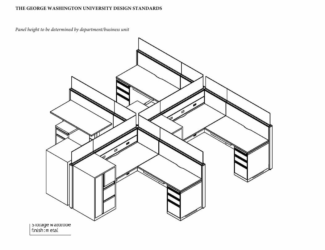
Panel height to be determined by department/business unit
THE GEORGE WASHINGTON UNIVERSITY DESIGN STANDARDS

Panel height to be determined by department/busines unit
THE GEORGE WASHINGTON UNIVERSITY DESIGN STANDARDS

FACILITIES RESOURCES AND PLANNING
Workstation Color Palette 1: Neutral
Exterior Panel: Metal Paint: Light Metallic Grey
Willow Grey TUN Tungsten

THE GEORGE WASHINGTON UNIVERSITY DESIGN STANDARDS
Panel Interior Fabric: Grey Work Surface: Light Maple
Tek TX67 Mesh CMB Clear Maple

THE GEORGE WASHINGTON UNIVERSITY DESIGN STANDARDS
Workstation Color Palette 2: Buff and Blue
Aisle Panel:
Metal Paint: Light Metallic Grey
CMB Clear Maple TUN Tungsten
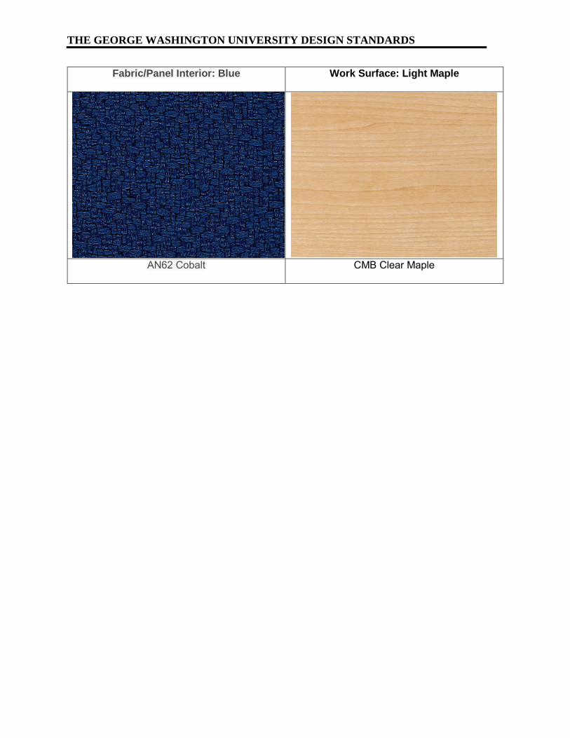
THE GEORGE WASHINGTON UNIVERSITY DESIGN STANDARDS
Fabric/Panel Interior: Blue Work Surface: Light Maple
AN62 Cobalt CMB Clear Maple

THE GEORGE WASHINGTON UNIVERSITY DESIGN STANDARDS
Workstation Color Palette : Cool
Exterior Panel: Light Maple Metal Paint: White
WGY Willow Grey DWT White

THE GEORGE WASHINGTON UNIVERSITY DESIGN STANDARDS
Panel Interior Fabric: Grey Work Surface: Grey Wood
Tek TX67 Mesh ACJ Absolute Acajou

THE GEORGE WASHINGTON UNIVERSITY DESIGN STANDARDS
Exterior Panel – 3 Segments
Top 6”: Pale Gold (AN43 Straw) Middle 12”: Metal (TUN)
Bottom 24”: Wood (Absolute Acajou)
Metal Paint: Light Metal (TUN)
Workstation Color Palette 4: Warm

THE GEORGE WASHINGTON UNIVERSITY DESIGN STANDARDS
Panel Interior Fabric: Pale Gold Work Surface: Textured Laminate
AN43 Straw Brushed Cobalt BRCLP/BRCHP
_________________________________________________________________________
_________________________________________________________________________ Division 12 00 00 – Furnishings 1 12 93 13 Bike Racks Revision date: 4/1/20 Document date: 1/1/16
THE GEORGE WASHINGTON UNIVERSITY DESIGN STANDARDS This document provides design standards only, and is not intended for use, in whole or in part, as a specification. Consultants referencing this information must always meet all applicable state and local building codes as well as all barrier free design requirements. Consultants must also refer to the entire set of Design Standards for additional information. Refer questions and comments regarding the content and use of this document to the George Washington University Project Manager.
12 93 13 BICYCLE RACKS
A. SUMMARY
This section contains standards for bicycle racks. For bike racks to be located in the Furnishing Zone of the streetscape at the Foggy Bottom campus, refer to The Foggy Bottom Streetscape Plan.
1. Reference Standards:
a. DDOT Bicycle Facility Design Guide b. DDOT Design and Engineering Manual, Chapter 28, Bicycle Facilities and
Shared Paths c. Association of Pedestrian and Bicycle Professionals (APBP) Bicycle Parking
Guidelines.
B. PRODUCTS Bicycle Rack for Exterior Courtyard: 1. Type:
a. The approved design is the inverted-U rack style. Each inverted U rack will count as two bicycle parking spaces.
2. Rack Elements: a. Secure bike anchorage b. Heavy-duty, tamper-resistant construction c. Provide support to the bicycle frame in at least 2 places, allowing the frame
and wheel to be locked by a cable or U-lock d. Prevent the wheel of the bike from overturning e. Accommodate front-in or back-in parking f. Not damaging to the bicycle frame
3. Anchoring: In-ground-mounted 4. Dimension: 1.5”D x 28.25”W x 32”H 5. Construction:
a. Materials: 1-1/2” o.d., 120” wall stainless steel tubing i. Finish: #4 satin electro polish finish on bare stainless steel
6. Quantity and Capacity: As indicated on Drawings. If project is targeting LEED credit under Sustainable Sites, Credit 4.2 Alternative Transportation, Bicycle Storage and Changing Rooms, provide quantity to comply with LEED requirements.
7. Approved bicycle rack manufacturers: a. Basis of Design:
i. Bola by Landscapeforms ii. Equivalent products/manufacturers approved by DDOT

THE GEORGE WASHINGTON UNIVERSITY DESIGN STANDARDS
_________________________________________________________________________ Division 12 00 00 – Furnishings 2 12 93 13 Bike Racks Revision Date: 4/1/20 Document date: 1/1/16
8. Setbacks: a. Wall Setbacks:
i. For racks set parallel to a wall: Recommended: 24”
ii. For racks set perpendicular to a wall: Recommended: 36”
b. Distance Between Racks: i. Recommended: 36"
c. Follow spacing recommended by Association of Pedestrian and Bicycle Professionals
9. Installation Methods: a. In-ground mounting shall be provided for new construction/major renovation
projects.
Bicycle Rack for Bike Storage Rooms: 1. Space Use:
a. Bike racks will hang vertically to maximize efficient use of space. Refer to manufacturer specifications for required setbacks.
2. Approved bicycle rack products and manufacturer: a. Basis of Design:
i. Ultra Space Saver by Dero Bike Rack Company ii. Bike File by Dero Bike Rack Company
3. Finish (Ultra Space Saver): a. Manufacturer’s standard factory-applied polyester powder coat paint finish b. Color: Black c. Hanger Rods: Rubber-coated
4. Refer to manufacturer specifications for required installation methods.

THE GEORGE WASHINGTON UNIVERSITY DESIGN STANDARDS
_________________________________________________________________________ Division 12 00 00 – Furnishings 3 12 93 13 Bike Racks Revision Date: 4/1/20 Document date: 1/1/16
5. Quantity and Capacity: As indicated on drawings, in Bike Storage Room. If project is targeting LEED credit under Sustainable Sites, Credit 4.2 Alternative Transportation, Bicycle Storage and Changing Rooms, provide quantity to comply with LEED requirements.
C. ANCHORS AND FASTENERS
1. Provide fasteners recommended by accessory manufacturer, appropriate for
proper attachment to supporting substrates 2. Provide theft-resistant fasteners or anchor security caps for exposed mountings 3. Match finish of fastenings to finish of bike racks
D. WHEEL STOPS 1. Description: Precast concrete wheel stops/bumpers 2. Quantity and locations: As indicated on Drawings 3. Finish: Manufacturer’s standard smooth form finish 4. Provide with ¾ inch diameter hot-dipped galvanized steel dowels, minimum 2 per
wheel stop, for securing wheel stops to slab
END OF SECTION

_________________________________________________________________________
_________________________________________________________________________ Division 12 00 00 – Furnishings 1 12 93 43 Site Seating and Tables Revision date: 7/1/19 Document date: 9/22/09
THE GEORGE WASHINGTON UNIVERSITY DESIGN STANDARDS This document provides design standards only, and is not intended for use, in whole or in part, as a specification. Consultants referencing this information must always meet all applicable state and local building codes as well as all barrier free design requirements. Consultants must also refer to the entire set of Design Standards for additional information. Refer questions and comments regarding the content and use of this document to the George Washington University Project Manager.
12 93 43 SITE SEATING AND TABLES
A. SUMMARY
This section contains design standards for site seating and tables.
B. PUBLIC SPACES
The following furniture shall be provided campus-wide in public areas. The furniture manufacturer is Landscapeforms.
1. Tables:
a. Model: Quad base, round table b. Table surface: Steelhead (perforated) c. Size: 36” diameter d. Material: Powder-coated metal e. Table top color: Silver f. Support color: Silver g. Umbrella hole to be provided h. Tables can be freestanding or surface-mounted as needed to meet program
requirements. 2. Seating:
a. Model: Verona b. Style: Perforated c. Height: Standard d. Features: Stackable
i. Seating count, including wheelchair access: as required 3. Umbrella: optional, as required by site conditions and sun exposure
a. Model: Equinox b. Fabric: Sunbrella marine-grade fabric with stain resistance c. Color: Marine Blue
4. Benches: a. Model: Parc Vue b. Length: 72: c. Style: Backed or backless d. Powdercoat Color: Silver e. Benches shall be freestanding or surface-mounted as needed to meet
program requirements. 5. Picnic Tables and Benches:
a. Model: Harvest b. Length: 94.75” c. Table top color: Charcoal or white d. Base, powdercoat color: Charcoal or white

THE GEORGE WASHINGTON UNIVERSITY DESIGN STANDARDS
_________________________________________________________________________ Division 12 00 00 – Furnishings 2 12 93 43 Site Seating and Tables.doc Revision date: 7/1/19 Document date: 9/22/09
6. High top tables and lounge tables: a. Model: Morrison b. Color per design c. Height per design d. Table top: Finish and color per design
7. Stools for high top tables: a. Model: Morrison or Chipman b. Color per design
C. PRIVATE SPACES – RESIDENCE HALLS
The following furniture shall be provided for courtyards, front porches, or other outdoor residence hall spaces that are not accessible to the public.
1. Lounge Furniture:
a. Manufacturer and Product: i. Polywood, Classic Folding Adirondack 5-Piece Conversation Group
2. Dining/Study Furniture: a. Manufacturer and Product:
i. Polywood, Classic Adirondack Dining 5-Piece Set ii. Polywood, Vineyard 7-Piece Nautical Trestle Dining Set
a.) Umbrellas shall be provided, as needed. 3. Chairs/non-lounge:
a. Manufacturer and Product: i. Polywood, South Beach Casual Chair
4. End Tables: a. Manufacturer and Product:
i. Polywood, 18” Round Table, 18” Side Table a.) Color: Slate Grey

_________________________________________________________________________
_________________________________________________________________________ Division 14 00 00 – Conveying Equipment 1 14 21 00 Elevators Revision date: 4/16/18 Document date: 9/22/09
THE GEORGE WASHINGTON UNIVERSITY DESIGN STANDARDS This document provides design standards only, and is not intended for use, in whole or in part, as a specification. Consultants referencing this information must always meet all applicable state and local building codes as well as all barrier free design requirements. Consultants must also refer to the entire set of Design Standards for additional information. Refer questions and comments regarding the content and use of this document to the George Washington University Project Manager.
14 21 00 ELEVATORS A. SUMMARY
This section contains the standards for passenger and freight elevators including cars, entrances, controls, safety equipment, hoistway equipment, and elevator machinery. Refer to building space standards for additional information.
B. GENERAL
1. Reference Standards:
a. Safety Code for Elevators and Escalators ASME A17.1, including errata, interpretations and revisions, as adopted by the District of Columbia and all modifications to ASME A17.1 contained within all applicable District of Columbia Ordinances, Interpretations and Revisions.
b. Inspectors’ Manual for Electric Elevators- ASME A17.2.1. c. American National Standard, Accessible and Usable Buildings and facilities-
CABO/ANSI A117.1 and Accessibility Guidelines for Buildings and Facilities, issued July 26, 1991 by the United States Architectural and Transportation Barriers Compliance Board as adopted by the American with Disabilities Act (ADA), including clearances, control and jamb signage, locations for signal equipment, door timing cycles, and similar provisions. The more stringent code on the issue shall be reinforced.
d. Requirements for Elevator and Escalator Electrical Equipment - CAN/CSA- B44.1/ASME-A17.5.
e. Qualification of Elevator Inspectors - QEI-1. f. National Electrical Code - ANSI/NFPA 70. g. National Fire Alarm Code - ANSI/NFPA 72. h. Installation of Sprinkler Systems - ANSI/NFPA 13. i. Life Safety Code - ASME/NFPA No. 101. j. Requirements of the local Fire Authority. k. Requirements of the BOCA National Building Code and any other code,
ordinance, or law applicable within the Governing Jurisdiction. l. American Welding Society (AWS) - D1.1 - Structural Welding Code - Steel. m. National Electrical Manufacturers Association (NEMA). n. Underwriters Laboratories Inc. (UL).
2. Protective Blanket Lining: Full-height, heavy cotton duck, padded and quilted, removable, with brass grommets. Provide permanent hooks in car.
3. Elevator Control Room: a. The controller shall be located adjacent to the hoistway. Coordination of final
placement to be conducted by the elevator manufacturer and subcontractor.

THE GEORGE WASHINGTON UNIVERSITY DESIGN STANDARDS
_________________________________________________________________________ Division 14 00 00 – Conveying Equipment 2 14 21 00 Elevators Revision date: 4/16/18 Document date: 9/22/09
b. Provide an emergency 120 volt duplex outlet (red in color) in the elevator control room for the computer monitor.
C. ELEVATORS
1. Elevator Description, General: Provide elevator schedule to accommodate project program criteria. a. Operation System: Selective-collective automatic operation b. Auxiliary Operations (where more than one elevator/bank of elevators):
i. Battery-powered lowering ii. Automatic dispatching of loaded car iii. Loaded-car bypass
2. Hoistway Entrances: a. Frames: Satin stainless steel, No. 4 finish b. Doors: Satin stainless steel, No. 4 finish
3. Security Features – Residence Halls and other building types as required a. Card-reader operation
4. Hall Fixtures: Satin stainless steel, No. 4 finish 5. Additional Requirements:
a. Provide inspection certificate in each car, mounted under acrylic cover with frame made from satin stainless steel, No. 4 finish.
b. Provide hooks for protective pads and complete set(s) of full-height protective pads.
c. Infrastructure that is required to be installed in the elevator pit will need to be suitable for wet locations. All wiring shall be inside rigid or liquidtight raceway. Electrical junction boxes shall be NEMA Type 4.
D. OPERATION PERFORMANCE
1. The control system shall provide smooth acceleration and deceleration with 1/8”
leveling accuracy at all landings, from no load to full rated load in the elevator, under normal or unloading conditions. The self-leveling shall, within the zone, be entirely automatic and independent of the operating device and shall correct for overtravel and undertravel. The car shall remain at the landing irrespective of load. Clearance between the car sill and the hoistway shall not exceed 1-1/4”.
2. Noise and Vibration Control: a. Airborne Noise: Measured noise level at elevator equipment and its
operation shall not exceed 60 dbA inside car under any condition including door operation and car ventilation exhaust blower on its highest speed. Limit noise level in the machine room relating to elevator equipment and its operation to no more than 80dBA.
b. Vibration Control: All elevator equipment and their support shall be mechanically isolated from the building structure and electrically isolated from the building power supply and to each other to minimize the possibility of objectionable noise and vibrations being transmitted to occupied areas of the building.

THE GEORGE WASHINGTON UNIVERSITY DESIGN STANDARDS
_________________________________________________________________________ Division 14 00 00 – Conveying Equipment 3 14 21 00 Elevators Revision date: 4/16/18 Document date: 9/22/09
E. SYSTEMS 1. Elevator Machines: Variable-voltage, variable frequency, ac-type hoisting
machines and solid-state power converters. 2. Fluid for Hydraulic Buffers: If using hydraulic buffers, use only fire-resistant fluid. 3. Inserts: Furnish required concrete and masonry inserts and similar anchorage
devices for installing guide rails, machinery, and other components of elevator work.
4. Machine Beams (Traction Elevators): Provide framing to support elevator hoisting machine and deflector sheaves from the building structure.
5. Car Frame and Platform: Bolted- or welded-steel units. 6. Guides: Roller guides or polymer-coated, non-lubricated sliding guides. Provide
guides at top and bottom of car and counterweight frames.
F. OPERATION SYSTEMS 1. General: Provide manufacturer’s standard microprocessor operation systems as
required. 2. Auxiliary Operations: In addition to primary operation system features, provide
the following operational features: a. Single-Car Battery-Powered Lowering: If power fails and car is at a floor, it
remains at that floor, opens its doors, and shuts down. If car is between floors, it is lowered to the next floor below, opens its doors, and shuts down. System includes rechargeable battery and automatic recharging system.
b. Automatic Dispatching of Loaded Car: When car load exceeds 80 percent of rated capacity, doors begin closing.
c. Governor must be self-resetting. 3. Diagnostic Tools: Provide diagnostic tools for servicing elevator equipment for
the elevator controller and hoisting means. 4. Security Operation:
a. Provide connection to a card reader or proximity reader, wall-mounted proximate to the call buttons for call button activation. Security readers to be provided by Owner.
b. GWorld Card Reader: The insertion of magnetic card reader or indication of a proximity reader card activates the designated floor car call. Pressure on the designated floor car button illuminates and registers a call. The elevator proceeds to the designated floor, completes its operation and awaits next demand.
5. Car Top Inspection Operation: Provide car top controls, lighting and inspection station in accordance with Code requirements.
6. Fire Service Emergency Recall Operation: Provide operation and equipment per Code requirements.
7. Standby Power Panel and Operation: a. Elevator Contractor shall provide all control wiring for automatic emergency
power operation of the elevator at contract speed. b. Include all software, relays, auxiliary contacts for emergency operation
control as part of the onboard features of the control system.

THE GEORGE WASHINGTON UNIVERSITY DESIGN STANDARDS
_________________________________________________________________________ Division 14 00 00 – Conveying Equipment 4 14 21 00 Elevators Revision date: 4/16/18 Document date: 9/22/09
c. Emergency operation shall be arranged such that the elevator system shall receive a signal of loss of normal power at the controller.
d. Provide standby power as required by code, at a minimum. e. Provide key switch and illuminated “Emergency Power Operation” signal for
each elevator at designated landing. Design elevators for emergency operation of one elevator at a time at contract speed. Incorporate main lobby faceplate.
f. Provide a fireman’s box with a key in the main lobby. The box shall be recess-mounted in the wall.
8. Fire Room Annunciator Monitor (High Rise Buildings): Provide the necessary software, communications hardware and associated inter-connections and wiring to allow for the annunciation of the elevators position and status to be transmitted and monitored remotely in the Fire Control Room. Locate all necessary equipment in the Fire Control Room, as required.
9. Provide elevator control circuitry that automatically shuts off the interior car lighting and fan the elevator is not in use. Control circuitry shall comply with ASME A17.1.
G. DOOR OPENING DEVICES
1. Infrared Reopening Device: Black, fully enclosed device with full screen infrared
matrix or multiple beams extending vertically along leading edge of each door panel to minimum height of 7’-0” above finished floor. De-speed shall prevent doors from closing and reverse doors at normal opening nudging operation. In event of device failure, provide for automatic shutdown of car at floor level with doors open.
2. Nudging Feature: After car doors are prevented from closing for predetermined adjustable time interval (min. 20.0 – 25.0 seconds), warning signal shall sound and doors shall attempt to close with a maximum of 2.5 foot pounds kinetic energy. Activation of the door open button shall override nudging operation and reopen doors.
H. CAR ENCLOSURES
1. Provide manufacturer’s standard steel car enclosure with access doors, power
door operators, and ventilation. a. Provide standard railings on car tops where required.
2. Materials and Finishes, Passenger and Freight, Typical: a. Subfloor: b. Floor Finish:
i. New Construction/Major Renovations: Agglomerate or terrazzo tile or equal hard, highly durable surface to match lobby flooring
ii. Existing Building Retrofit Projects: Rubber flooring (See 09 65 00 Resilient Flooring, J. Elevator Cab Flooring)
c. Wall Panels: Stainless-steel; flush hollow metal construction; fabricated from stainless steel sheet i. Return Panels: Stainless steel cladding ii. Side and Rear Panels:

THE GEORGE WASHINGTON UNIVERSITY DESIGN STANDARDS
_________________________________________________________________________ Division 14 00 00 – Conveying Equipment 5 14 21 00 Elevators Revision date: 4/16/18 Document date: 9/22/09
a.) Residence Halls: Patterned stainless steel cladding, Rimex 5-SM or approved equal
b.) Academic and Administrative Buildings: Plastic laminate cladding with stainless steel trim and reveals
d. Base: Stainless steel e. Car shall be fabricated with recesses and cutouts for signal equipment. f. Car door frame shall be integral with front wall of car. g. Doors: Stainless steel; manufacturer’s standard
i. No. 4, satin, directional polish. Apply directional finishes in long direction of each component
h. Sills: Extruded metal, with grooved surface, ¼” thick i. Ceiling: Stainless steel suspended ceiling with round LED downlights j. Handrails:
i. Stainless steel, round tube 1-1/2 inch diameter, with closed ends ii. Provide for rear and side walls
a.) Acceptable product and manufacturer: Equivalent to Otis DH 156 by Otis
iii. Provide bumper rails, at side and rear walls, mounted at a height to protect the walls of the car enclosure from impact from carts, as required, depending upon building usage.
I. HOISTWAY ENTRANCES 1. Hoistway entrance assembles: Provide manufacturer’s standard horizontal-
sliding, door-and-frame hoistway entrances complete with track systems, hardware, sills and accessories. Frame size and profile shall accommodate hoistway wall construction.
2. Entrances shall bear fire labels from a nationally recognized testing laboratory approved within the governing jurisdiction.
J. SIGNALING EQUIPMENT 1. General: Provide hall-call and car-call buttons that light when activated and
remain lit until call has been fulfilled. Provide flat buttons with white LED illuminated halo, satin stainless steel finish.
2. Car Control Stations: Provide manufacturer’s standard recessed car-control stations. Mount in return panel adjacent to car door unless otherwise required. a. Mark buttons and switches shall utilize both tactile symbols and Braille. b. Provide “No Smoking” sign matching car-control station, either integral with
car-control station or mounted adjacent to it, with text and graphics required per local jurisdiction.
3. High Rise Buildings, Emergency Communication System: Two-way voice communication system, vandal-resistant, with visible signal, which dials preprogrammed number of monitoring station and does not require handset use. System is contained in flush-mounted cabinet, with identification, instructions for use, and battery backup power supply.
4. Car Position Indicator: Provide illuminated, digital-type car position indicator, located above car door or above car control station. Also, provide audible signal

THE GEORGE WASHINGTON UNIVERSITY DESIGN STANDARDS
_________________________________________________________________________ Division 14 00 00 – Conveying Equipment 6 14 21 00 Elevators Revision date: 4/16/18 Document date: 9/22/09
to indicate to passengers that car is either stopping at or passing each o f the floors served. Include travel direction arrows if not provided in car-control station.
5. Hall Push-Button Push Stations: Provide one hall push-button at each landing. 6. Hall Lanterns: Units with illuminated arrows; but provide single arrow at terminal
landings. Provide manufacturer’s standard wall-mounted units, for mounting above entrance frames.
7. Hall Annunciator: With each hall lantern, provide audible signals indicating car arrival and direction of travel. Signals sound once for up and twice for down. a. At manufacturer’s option, audible signals may be placed on cars.
8. Hall Position Indicators: Provide illuminated, digital-display-type position indicators, located above each hoistway entrance.
9. Jurisdictional Compliance: Provide all accessories and items required by jurisdiction.
K. PRODUCTS AND MANUFACTURERS
1. General: Acceptable manufacturers must have sales, service, and technical
support readily available to the University. Due to issues with quality and technical support for equipment troubleshooting experienced by GW with proprietary equipment and to allow the University to maintain an independent service contractor, specifications shall be non-proprietary equivalent to Motion Control Equipment (MCE), including, but not limited to, software, tools, manuals, interfaces, etc.
2. Standard of quality for elevators is established by products installed by the following manufacturers: a. Otis Elevator Co. b. MCE c. Galaxy d. Other manufacturers and products may be incorporated into a project
provided they are approved by GW and comply with the requirements noted in this section.
3. MRL (Machine Room-less) Elevators: a. Approved Manufacturer and Product, or Approved Equal (by GW Facilities
Services): i. Otis Gen 2
L. DEMONSTRATION 1. A factory-authorized service representative shall train Owner’s maintenance
personnel to operate, adjust, and maintain elevator (s). 2. Operation of elevator(s) shall be verified with Owner’s personnel present before
date of Substantial Completion and again not more than one month before end of warranty period. Operation systems and devices shall be determined to be functioning properly.
M. TESTING/COMMISSIONING
1. Conduct the following operating testing procedure for each elevator: Load each elevator to the rated capacity and operate continuously for 8 hours over the full

THE GEORGE WASHINGTON UNIVERSITY DESIGN STANDARDS
_________________________________________________________________________ Division 14 00 00 – Conveying Equipment 7 14 21 00 Elevators Revision date: 4/16/18 Document date: 9/22/09
travel distance, stopping at each level and proceeding immediately to the next. If any type of performance failure occurs, restart and conduct the full operating test on the following day.
2. Testing tools shall be operable without the need for entering passwords or codes. 3. Ensure submittals are reviewed by reliable third party elevator expert. 4. Provide elevator certificates and inspection reports, along with all keys and
testing tools to GW Facilities Services upon project completion.
N. INSPECTION
1. All elevator inspections including construction use inspection and final elevator inspection shall be completed by NEIS Elevator Inspection Co; no exceptions.
END OF SECTION
_________________________________________________________________________
_________________________________________________________________________ Division 14 00 00 – Conveying Equipment 1 14 91 82 Trash Chutes Revision date: 7/1/14 Document date: 9/22/09
THE GEORGE WASHINGTON UNIVERSITY DESIGN STANDARDS This document provides design standards only, and is not intended for use, in whole or in part, as a specification. Consultants referencing this information must always meet all applicable state and local building codes as well as all barrier free design requirements. Consultants must also refer to the entire set of Design Standards for additional information. Refer questions and comments regarding the content and use of this document to the George Washington University Project Manager.
14 91 82 TRASH CHUTES A. SUMMARY
This section contains design standards for trash chutes. See design standards by building type for additional information.
B. GENERAL
1. Trash chute
a. Chute opening should be 24” x 24” or 30” diameter; aluminized steel; minimum 16 gage.
b. Factory spray chute components with sound dampening material c. Provide fire sprinklers as required per NFPA 13. Sheet metal for chute
construction shall overlap from top to bottom such that if sprinklers are set off, water stays within the chute rather than escaping the seams between sections.
d. Automatic flush and sanitizing unit shall not be provided. e. A plumbing access door is not required.
2. Intake Doors (and Frames): a. Manufacturer’s standard ASTM A240/A240M, Type 304 stainless steel, doors
shall be self-closing units with positive latch and latch handle with 1-1/2 hr fire-rated construction with frame suitable for enclosing chase construction.
b. Door size and type: 15” W X 18” H, bottom hinged, hopper type c. Finish: Manufacturer’s standard satin directional polish finish
3. Discharge: a. Aluminized steel, minimum 16 gage; Type A open end chute discharge rolling
steel door with fusible link hold-open on inclined steel track at bottom of chute to close automatically at temperature threshold per code.
b. Door size: 26-1/2” X 50-1/2” 4. Roof Vent:
a. Provide a relief vent at the top of the chute extending above roof per NFPA and as required per manufacturer’s specifications.
b. Roof vent shall extend to 48” above roof with full-diameter, screened vent and metal safety cap or glass explosion-release cap.
END OF SECTION

_________________________________________________________________________
_________________________________________________________________________ Division 21 00 00 – Fire Suppression 1 21 13 00 Fire Suppression Systems Revision date: 4/1/19 Document date: 7/1/10
THE GEORGE WASHINGTON UNIVERSITY DESIGN STANDARDS This document provides design standards only, and is not intended for use, in whole or in part, as a specification. Consultants referencing this information must always meet all applicable state and local building codes as well as all barrier free design requirements. Consultants must also refer to the entire set of Design Standards for additional information. Refer questions and comments regarding the content and use of this document to the George Washington University Project Manager.
21 13 00 FIRE-SUPPRESSION SPRINKLER SYSTEMS A. SUMMARY
This section contains design standards for fire suppression systems. Refer to space standards and related specification guidelines for additional information.
B. GENERAL
1. All new construction and major renovation projects shall be equipped with a fire
suppression system. 2. For most buildings, the system will be a hydraulically-designed, wet pipe,
automatic sprinkler system. 3. The fire suppression system shall be designed and installed in compliance with
the latest edition of NFPA standards including NFPA 13, "Standard for the Installation of Sprinkler Systems," NFPA 14 "Standard for the Installation of Standpipes and Hose Systems" (as well as NFPA 20, “Standard for the Installation of Centrifugal Fire Pumps.”
4. The sprinkler system shall be designed and installed in accordance with the current edition of applicable building codes, FM Global requirements, and ADA.
5. The sprinkler system design, and the contractor submittals, including all layout drawings and installation details, equipment and material data, specifications, occupancy details, and hydraulic calculations shall be submitted to FM Global for their review and approval. For additional information on FM Global requirements, refer to “Plan Review and Construction Project Guidelines for The George Washington University, Washington, DC”.
6. All sprinklers, valves, devices, and fittings should be FM Approved. 7. It shall be the Contractor's responsibility to develop a complete set of shop
drawings for the installation of the system. These Drawings shall be approved by the AHJ Fire Marshall's office and FM Global prior to any fabrication and/or installation.
8. Sprinkler Coordination: Layout and installation of fire protection piping and sprinkler heads shall be coordinated with other construction so as not to interfere with the work of other trades. Sprinkler Contractor shall cooperate in the preparation of coordination drawings, when they are required on a specific project.
9. Comply with “FM Global Red Tag Permit System” for all work that disables operation of any portion of a fire suppression system.

THE GEORGE WASHINGTON UNIVERSITY DESIGN STANDARDS
_________________________________________________________________________ Division 21 13 00 – Fire Suppression 2 21 13 00 Fire Suppression Systems Revision date: 4/1/19 Document date: 7/1/10
C. SYSTEM DESCRIPTION 1. Design and Performance Requirements, General:
a. Refer to FM Global requirements for recommended sprinkler system design criteria including coverage requirements, guidance on sprinkler temperature ratings, water supply, and hydraulic calculation procedures.
b. Hydraulically design the sprinkler system using an area-density procedure acceptable to FM Global.
c. Safety Factor: Provide a 10 psi hydraulic safety factor. d. Hydraulic Calculations: FM Global allows the hose stream allowance in
hydraulic calculations to be taken at the street hydrant. For residential areas of buildings, FM Global allows a hydraulic area to be defined taken as the sprinkler heads within an apartment unit, less those in small closet rooms, combined with the four closest heads in the corridor along the path of egress. Confirm current requirements with FM Global.
2. System Piping: a. All sprinkler piping shall be concealed in ceilings, walls or soffits to the extent
possible. 3. Escutcheons:
a. Wall and Ceiling Escutcheon Plates: Provide for sprinkler and standpipe piping passing through walls and ceilings approved type, one-piece or split type escutcheon plates. Secure plates in place with set screws or other approved positive means.
D. SPRINKLERS
1. Sprinkler Heads:
a. Sprinkler Applications: i. Rooms without ceilings: Upright sprinklers with appropriate temperature
ratings ii. Rooms with suspended ceilings: Pendent – concealed, recessed, and
flush sprinklers iii. Wall Mounting: Sidewall sprinklers protected with a cap
a.) To achieve coverage within larger residential dwelling units from sidewalls at the entry bulkhead, concealed, extended coverage sprinkler heads with a fusible link are recommended to avoid constructability issues and cost impact. There is not an FM Approved sprinkler head of this type. Designer shall propose a UL-listed, extended coverage, horizontal sidewall type of sprinkler head, equipped with a concealing cover, for FM Global plan review and approval.
2. Protection of Sprinkler Heads: a. All sprinkler heads shall be the concealed type wherever possible. b. All sprinkler heads in residence halls shall be concealed or protected with a
cap designed for protection against tampering and dust. c. Wire-cage type sprinkler guards shall be provided for sprinklers in all stair
areas, telecommunications rooms, mechanical rooms, elevator machine

THE GEORGE WASHINGTON UNIVERSITY DESIGN STANDARDS
_________________________________________________________________________ Division 21 13 00 – Fire Suppression 3 21 13 00 Fire Suppression Systems Revision date: 4/1/19 Document date: 7/1/10
rooms, electrical rooms, janitor’s closets and in any other areas where the activity in the space could result in accidental damage to sprinkler heads.
E. DRAINS 1. All sprinkler system test drains shall be plumbed to an express drain. Express
drain shall terminate outside or to an adequately sized sump.
F. DRY SYSTEMS 1. Dry sprinkler system valves: shall be model TYCO DPV-1 2. Dry sprinkler pipe and pre-action systems shall be provided with FM Approved
galvanized steel piping. 3. Tank Mounted Compressors:
a. Shall be provided on systems serving more than 4 sprinkler heads unless otherwise approved by GWU Life Safety.
b. Shall be rated a minimum of 1 HP, 10 Gallon serving up to 2 systems. c. Shall be rated a minimum of 1 HP, 30 Gallon serving up to 4 systems.
G. INSTALLATION 1. Contractor shall be responsible for all measurements at site and checking
correctness of same as related to project work. 2. Contractor shall be responsible for project work and equipment until finally
inspected, tested, and accepted; work shall be protected against theft, injury, or damage, and materials shall be stored carefully including equipment received on site which is not immediately installed. Close open ends of work with temporary covers or plugs during construction to prevent entry of obtrusive material.
3. Contractor shall provide all sidewalk and street repairs due to the installation of the siamese connections and new fire service to the buildings.
4. If at any time deficiencies in the work are discovered which result from work not in accordance with Contract documents, Contractor shall be held liable for replacement or correction, regardless of the time limit on the guarantee.
H. INSPECTIONS 1. GW Facilities Life Safety and QAA Inspector shall be notified prior to final
inspection
I. COMPLETION DOCUMENTS Shall include, but are not limited to, the following: 1. Sprinkler System:
a. Provide copies of all requirements: i. System Acceptance 100% Test
b. NFPA 13 Acceptance Requirements 10-2 i. Contractor’s Material and Test Certificate
c. NFPA 13 Instructions 10-4 i. All literature and instructions of any equipment and devices installed

THE GEORGE WASHINGTON UNIVERSITY DESIGN STANDARDS
_________________________________________________________________________ Division 21 13 00 – Fire Suppression 4 21 13 00 Fire Suppression Systems Revision date: 4/1/19 Document date: 7/1/10
d. NFPA 13 Hydraulic Design Information Signs 10-5
2. Fire Pumps: a. Provide copies of all requirements:
i. System Acceptance 100% Test b. NFPA 20 Acceptance Testing Chapter 14
i. 14.1.2 Hydrostatic Test ii. 14.2.4 Certified Pump Curve iii. 14.2.5.4 Measurement Procedure
END OF SECTION

_________________________________________________________________________
_________________________________________________________________________ Division 21 00 00 – Fire Suppression 1 21 31 13 Electric-Drive Centrifugal Fire Pumps.doc Revision date: 4/1/19 Document date: 7/1/11
THE GEORGE WASHINGTON UNIVERSITY DESIGN STANDARDS This document provides design standards only, and is not intended for use, in whole or in part, as a specification. Consultants referencing this information must always meet all applicable state and local building codes as well as all barrier free design requirements. Consultants must also refer to the entire set of Design Standards for additional information. Refer questions and comments regarding the content and use of this document to the George Washington University Project Manager.
21 31 13 ELECTRIC-DRIVE, CENTRIFUGAL FIRE PUMPS A. SUMMARY
This section contains design standards for fire pumps. Refer to related design standards and related specification guideline sections for additional information.
B. GENERAL
1. The preferred type of fire pump for buildings at The George Washington University is a horizontal, split case, double suction, centrifugal pump. The complete fire pump and controller assembly should be Factory Mutual listed.
2. Where required due to available floor space, vertical split-case model fire pumps shall be used, no exceptions.
END OF SECTION
_________________________________________________________________________
_________________________________________________________________________ Division 22 00 00 - Plumbing 1 22 00 00 Plumbing, General Requirements Revision date: 7/1/19 Document date: 7/1/11
THE GEORGE WASHINGTON UNIVERSITY DESIGN STANDARDS This document provides design standards only, and is not intended for use, in whole or in part, as a specification. Consultants referencing this information must always meet all applicable state and local building codes as well as all barrier free design requirements. Consultants must also refer to the entire set of Design Standards for additional information. Refer questions and comments regarding the content and use of this document to the George Washington University Project Manager.
22 00 00 PLUMBING
A. SUMMARY
This section contains GW-specific, general requirements for plumbing work. Refer to building type space standards and related specification guidelines for additional information.
B. STANDARDS
1. General:
a. Refer to related specification guideline sections for additional information including the following: 22 11 19 Domestic Water Piping Specialties, 22 42 00 Commercial Plumbing Fixtures and 22 47 00 Water Coolers.
b. Metering: i. DC Water owns all of the water meters in DC, and configures them with
an automated meter reading (AMR) system to be read remotely. All new water meters should be set in such a way as to allow a radio-signal-sending device to be located near a building’s exterior wall or a manhole outside. GW’s Energy and Environmental Management Office (EEMO) can help the construction team acquire the meter, strainer, and AMR unit from DC Water. For buildings with water-based cooling towers, three separate DC Water meters will be installed (or retained for existing buildings): main meter to building, cooling tower make-up, and cooling tower blowdown. Loudoun Water uses only two meters: main meter to building and cooling tower make-up.
ii. GW’s general policy is that all on-campus, independently-operated venues (e.g. Starbucks’) are submetered for all utilities
iii. GW prefers that new venue meters be from the same manufacturers as existing venue meters. a.) Natural Gas
a) For natural gas, most existing venue meters include Onicon Insertion Model F-5200 meters with Model D-100 remote readouts while IMAC or utility-provided gas meters are also used.
b.) Water Use a) For water, most existing venues meters are Metron-Farnier
Model 50DL with TruRead remote readouts while some venues use Badger, Carlon, or Neptune water meters (suitable for separate hot and cold water delivery-temperature ranges).

THE GEORGE WASHINGTON UNIVERSITY DESIGN STANDARDS
_________________________________________________________________________ Division 22 00 00 - Plumbing 2 22 00 00 Plumbing, General Requirements Revision date: 7/1/19 Document date: 7/1/11
c.) BTU Meters a) For BTU meters, most existing venues use Onicon Model 10
BTU meters while some use Siemens Sitrans F meters or a BTU calculation built into the BMS for HVAC chilled and hot water.
iv. It is the intent of the Owner to have the primary utility meters for large buildings, and leased space tenant submeters, electronically metered and to have the metering data imported into the BAS and EMS. BAS/EMS should monitor natural gas and water demand (cfh, gpm) and accumulate consumption (ft3, gal) at the main building utility meters – and at any submeters in the building, such as for leased space tenants.
2. Identification a. Refer to 23 00 00, HVAC, General Requirements, section 16. Identification,
for piping identification requirements. 3. Plumbing Pipe and Fittings:
a. Pipe joints shall be welded, soldered, or screwed, at all inaccessible locations, such as within shafts and chases, inside trenches and tunnels, and above hard ceilings.
b. In accessible locations, Victaulic mechanical pipe coupling systems may be used for fluid-filled lines under pressure, except where the temperature range of the conveyed fluid can vary by more than 60 degrees F.
c. Victaulic mechanical pipe coupling systems are not acceptable for use on pipes conveying potentially corrosive fluids.
d. ProPress/compression fittings shall only be used for repair. e. T-Drill method shall not be used.
4. Plumbing Valves and Specialties: a. All toilets and sinks in residence halls shall have a stop valve. b. Valve charts shall include the valve manufacturer and model. Valve
identification tags are not required on isolation and drain valves at fixtures and equipment.
c. Chain wheel operators are required on valves 3-inch and larger, located over 8 feet above the floor. For valves under 3-inch, chain wheels should only be provided if directed by GW.
d. Control valves shall have a pipe union at each connection end. 5. Plumbing Fixtures
a. General i. Sanitary waste lines from plumbing fixtures shall drain by gravity. Ejector
pumps shall only be used when plumbing fixtures are below the invert of the building sanitary main leading to the public sewer system.
ii. See also 22 42 00 Commercial Plumbing Fixtures for additional information.
6. Insulation a. All domestic water lines are to be insulated. Insulation shall fit tightly to
piping.

THE GEORGE WASHINGTON UNIVERSITY DESIGN STANDARDS
_________________________________________________________________________ Division 22 00 00 - Plumbing 3 22 00 00 Plumbing, General Requirements Revision date: 7/1/19 Document date: 7/1/11
7. Sanitary Drains for Cooling Towers
a. Furnish a sanitary riser, and indirect drain receptacles, all properly sized and situated to prevent overflow of condenser water onto adjacent floor and roof surfaces.
b. Overflow drain lines from tower sumps, and the receptacles they discharge into, shall both be sized to accommodate by gravity, the flow of water from the (pumped) tower make-up line.
c. Manual blowdown and drain lines from the towers shall discharge into receptacles visible by an operator at the blowdown or drain valve.
d. Automatic blowdown lines from the water treatment system, shall discharge into a properly sized drain receptacle, and shall include a throttling valve.
8. Cleaning and Flushing: The process of cleaning and flushing the interior of new piping systems will generate wastewater that must be disposed of in accordance with Title 21 of the DC Municipal Regulations. Besides compliance with DCMR Title 21, the following practices should be employed: a. Flushing water should be disposed of into the sanitary sewer system
(assuming the wastewater meets the DCMR and DCWASA standards for pH, metals, etc.)
b. Flushing water should be discharged through a strainer. Sludge and debris from the strainer should be treated as solid waste for disposal in a landfill.
c. To avoid the discharge of chemicals into the Potomac River caused by sewer overflows during wet weather; cleaning and flushing operations should be conducted during periods of dry weather.
9. Sewage Ejection a. Building levels below the sewer invert shall be served by a sewage grinder
pump in lieu of a sewage ejector pump.
END OF SECTION

_________________________________________________________________________
_________________________________________________________________________ Division 22 00 00 – Plumbing 1 22 11 19 Domestic Water Piping Specialties.doc Revision date: 7/1/18 Document date: 9/22/09
THE GEORGE WASHINGTON UNIVERSITY DESIGN STANDARDS This document provides design standards only, and is not intended for use, in whole or in part, as a specification. Consultants referencing this information must always meet all applicable state and local building codes as well as all barrier free design requirements. Consultants must also refer to the entire set of Design Standards for additional information. Refer questions and comments regarding the content and use of this document to the George Washington University Project Manager.
22 11 19 DOMESTIC WATER PIPING SPECIALTIES
A. SUMMARY
This section contains general standards for trap guards.
B. GENERAL Provide a trap guard in unattended traps where water may otherwise evaporate and allow sewer gas to escape. Floor drains in areas that are not mopped regularly shall have a trap guard. 1. Approved Product:
a. ProSet Trap Guard by ProVent Systems
2. Example locations are the following: a. floor drains in dorm room bathrooms (to prevent problems while students are
away, such as summer breaks) b. area floor drains in mechanical rooms c. area floor drains in laundry rooms d. area floor drains in lower levels of parking garages
END OF SECTION

_________________________________________________________________________
_________________________________________________________________________ Division 22 00 00 – Plumbing 1 22 11 23 Drain Pump Systems Document date: 1/1/14
THE GEORGE WASHINGTON UNIVERSITY DESIGN STANDARDS This document provides design standards only, and is not intended for use, in whole or in part, as a specification. Consultants referencing this information must always meet all applicable state and local building codes as well as all barrier free design requirements. Consultants must also refer to the entire set of Design Standards for additional information. Refer questions and comments regarding the content and use of this document to the George Washington University Project Manager.
22 11 23 DRAIN PUMP SYSTEMS
A. SUMMARY
This section contains general standards for drain pump systems for existing facilities.
B. GENERAL
For Conditions in Existing Buildings Only: Provide Drain Pump Series 105 by Zoeller Pump Company.
END OF SECTION

_________________________________________________________________________
_________________________________________________________________________ Division 22 00 00 – Plumbing 1 22 36 00 Rainwater Harvesting Systems Document date: 7/1/17
THE GEORGE WASHINGTON UNIVERSITY DESIGN STANDARDS This document provides design standards only, and is not intended for use, in whole or in part, as a specification. Consultants referencing this information must always meet all applicable state and local building codes as well as all barrier free design requirements. Consultants must also refer to the entire set of Design Standards for additional information. Refer questions and comments regarding the content and use of this document to the George Washington University Project Manager.
22 36 00 RAINWATER HARVESTING SYSTEMS
A. SUMMARY
This section contains design standards for rainwater harvesting systems designed to transfer, store, clarify, disinfect and treat harvested rain water to protect public health and safety, mitigate scaling and corrosion and maintain an aesthetic appearance.
B. GENERAL
1. Harvested rain water is intended to be used for non-potable use in the building
for toilet and urinal flushing or for irrigation. It is not intended to be used for cooling tower make-up.
2. The rain water system treatment methods include: a. Particulate filtration b. Chlorination
3. The system shall consist of packaged, modular unit treatment operations. Operation of the system shall by fully automatic.
C. QUALITY ASSURANCE QUALIFICATIONS
1. Equipment vendors shall have a minimum of three (3) years experience in
manufacturing relevant equipment and provide references for two (2) similar facilities.
END OF SECTION

_________________________________________________________________________
_________________________________________________________________________ Division 22 00 00 – Plumbing 1 22 42 00 Commercial Plumbing Fixtures Revision date: 1/1/20 Document date: 9/22/09
THE GEORGE WASHINGTON UNIVERSITY DESIGN STANDARDS This document provides design standards only, and is not intended for use, in whole or in part, as a specification. Consultants referencing this information must always meet all applicable state and local building codes as well as all barrier free design requirements. Consultants must also refer to the entire set of Design Standards for additional information. Refer questions and comments regarding the content and use of this document to the George Washington University Project Manager.
22 42 00 COMMERCIAL PLUMBING FIXTURES
A. SUMMARY
This section contains design standards for commercial plumbing fixtures. Refer to space standards for additional information.
B. EXCEPTIONS TO REQUIREMENTS HEREIN
1. There are retrofit projects where the plumbing fixture standards herein, as well as
in the building type standards should not be strictly applied. Different scenarios will require careful analysis as well as approval from the Director of Facilities Planning and Design Review. The following notes address some of the most common to be encountered: a. Where wall hung toilets are to be replaced, they shall typically be replaced by
wall-hung toilets in order to limit the plumbing work required in relocating the waste pipes. Floor-mounted toilets shall also be replaced with floor-mounted toilets for the same reason.
b. Existing floor-mounted toilets may be replaced with either flush valve or flapper/tank style toilets, as appropriate.
2. Where new residence hall bathrooms provide three or more toilets, it will often be advisable to install either wall-mounted or floor-mounted flush valve toilets, rather than the tank style required in more typical single-toilet private bathrooms. Flush valve toilets are more durable and capable of withstanding abuse than the residential tank style toilets. Wall-mounted toilets are more difficult to install than floor-mounted, but they offer a valuable housekeeping advantage when cleaning floors.
C. GENERAL
1. Vitreous china fixtures shall be manufacturer’s standard white color unless
otherwise approved. 2. Faucets, levers, sensors, and the like shall be ADA-compliant. 3. Faucets, levers, sensors, and the like shall be chrome-plated. 4. Tank style toilets shall have shut-off valves. Shut-off valves shall be operated by
a handle and not a key. a. For new construction, rigid supply tubing shall be used for the connection
between the stop valve and the toilet fixture. b. For renovation projects, flexible tubing shall be used for the connection
between the stop valve and the toilet fixture.

THE GEORGE WASHINGTON UNIVERSITY DESIGN STANDARDS
_________________________________________________________________________ Division 22 42 00 – Plumbing 2 22 42 00 Commercial Plumbing Fixtures Revision date: 1/1/20 Document date: 9/22/09
5. When installed with accompanying aerators, flush valves and related components, target water consumption for new construction fixtures shall be as follows or as required by the local code, whichever is more stringent: a. Toilets, residential/tank style: 1.28 gpf b. Toilets, commercial/wall-hung with flushometer: 1.28 gpf c. Urinals: .125 gpf d. Residential lavatory faucets: .5 gpm e. Commercial lavatory faucets, metering: .5 gpm f. Sink faucets: 1.5 gpm g. Shower heads: 1.75 gpm
D. TOILET, TANK STYLE – NEW CONSTRUCTION/MAJOR RENOVATIONS
1. Water consumption: 1.28 gpf; Material: vitreous china; Bowl Shape: elongated 2. Approved Manufacturer and Model, no exceptions:
a. Toto Eco Drake Close Coupled Toilet; Color: #01, Cotton i. Barrier free: CST744EL ii. Typical: CST744E
3. Toilet seat: Elongated seat, closed back, closed front, commercial class, solid white polypropylene, with cover, with stainless steel, self-sustaining check hinge. a. Model, or approved equal:
i. Church 380TC
E. TOILET, TANK STYLE – RETROFIT PROJECTS IN EXISTING BUILDINGS 1. Water consumption: 1.28 gpf; Material: vitreous china 2. For renovations of smaller bathrooms with door swing/clearance issues, one of
the following round front bowl models shall be provided: a. Approved Manufacturers and Models, no exceptions:
i. American Standard Cadet Pro Round Front Toilet: 215DA.104 (Color: white)
ii. Gerber Viper: HE-21-502 (Color: white) 3. Other renovations:
a. Approved Manufacturers and Models, no exceptions: i. Gerber Viper: HE-21-519, Compact Elongated (ADA accessible)
F. TOILET, WALL-HUNG
1. Material: vitreous china 2. Color: white 3. Water usage: 1.28 gpf, no exceptions without approval 4. Top spud inlet 5. Bowl Shape: elongated
a. Approved Porcelain Manufacturer and Model, no exceptions: i. Toto USA CT708E
6. Toilet touchless flush device and valve: a. Provide 1.28 gpf toilet flush valve. Valve shall be quiet, exposed, and suitable
for either right or left hand actuator installation. b. All metallic parts to be chrome plated finish.
THE GEORGE WASHINGTON UNIVERSITY DESIGN STANDARDS
_________________________________________________________________________ Division 22 42 00 – Plumbing 3 22 42 00 Commercial Plumbing Fixtures Revision date: 1/1/20 Document date: 9/22/09
7. Approved toilet-plus-valve system, no exception: a. Sloan Royal Flushometer 111-1.28 SFSM
8. Toilet seat: Elongated seat, closed back, open front, commercial class, solid white polypropylene, less cover, with stainless steel, self-sustaining check hinge. a. Model, or approved equal:
i. Church 9400C
G. URINAL, WALL-HUNG
1. Material: vitreous china 2. Color: White 3. Water usage: .125 gpf; no exceptions without approval 4. Top spud inlet 5. ADA-compliant 6. Urinal autoflush device and valve:
a. Provide .125 gpf urinal flush valve. Valve shall be quiet, exposed, and suitable for either right or left hand actuator installation.
b. Provide battery or solar-operated, automatic infrared sensor-activated actuator with manual override
c. All metallic parts to be chrome plated finish. 7. Approved urinal manufacturer and product, no exceptions:
a. Sloan Royal Flushometer 186-0.125 SFSM
H. AUTOMATIC FLUSH SENSOR FOR RETROFITS OF EXISTING SLOAN TOILETS 1. Approved product, no exception:
a. Sloan Single-Flush Side Mount, model EBV-500-A
I. LAVATORY FAUCET, TOUCHLESS WITH AUTO-SENSOR (PUBLIC RESTROOMS) 1. Cast brass construction, with polished chrome finish 2. Touchless, automatic sensor, thermal mixing style 3. Flow rate: .5 gpm 4. Shall allow setting for automatic cut-off after 10 seconds of continuous discharge.
Faucet shall also cease discharge within one second of detecting user has moved away.
5. Manufacturer’s warranty shall be a minimum of three years.
6. Approved Manufacturer and Model, no exception: a. Toto Self-Generating EcoPower System Sensor Faucet, standard spout,
TEL105-D10ET b. Provide manufacturer’s recommended cover plate sized to coordinate with
the spacing between the holes in the sink.
J. LABORATORY FAUCET (MEDICAL EXAM ROOMS, DIRTY & CLEAN SINKS, PHLEBOTOMY) 1. Cast brass construction, with polished chrome finish 2. Flow rate: 0.5 gpm

THE GEORGE WASHINGTON UNIVERSITY DESIGN STANDARDS
_________________________________________________________________________ Division 22 42 00 – Plumbing 4 22 42 00 Commercial Plumbing Fixtures Revision date: 1/1/20 Document date: 9/22/09
3. Approved Manufacturer and Model, no exception: a. T&S Model BL-5704-08WH4; Single Hole Deck Mount Lab. Mix. Faucet, 4”
Wrist Handles, Rigid Vaccum Breaker Nozzle, Serrated tip
K. LAVATORY FAUCET, MANUAL OPERATION (RESIDENTIAL USE ONLY)
1. Single lever, manual operation, ADA-compliant 2. Cast brass construction, with polished chrome finish 3. Maximum flow rate shall be 2.2 gpm
a. Provide vandal-resistant .5 gpm aerator i. Approved Manufacturers and Models, or equal:
a.) Moen; Model: 516711 b.) Omni Flow Controls, Low Flow; Model L-200 Series-VR-0.5
4. Style to be 4” centerset, deck-mounted 5. Unless otherwise approved by owner, including housing facilities, model to be
Moen Chateau ADA Single-Handle Lavatory Faucet, Model L4621. The Moen 1225 cartridge design of this model is favored by housing facilities for its proven reliability and simplicity of maintenance.
L. LAVATORY – PUBLIC RESTROOMS (ALL BUILDING TYPES)
1. Lavatory shall be wall-hung vitreous china; undermount stainless steel with solid
surface counter and back-/side-splashes; or solid surface lavatory top with integral bowl a. Wall-hung vitreous china (Single-Occupant Use)
i. Dimensions: approximately 20” L x 18” W; barrier-free depth ii. Provide without integral backsplash (tiled wall is required) iii. Provide without soap bar depression iv. Complete and proper installation is critical for strength and durability,
including proper installation of concealed wall hanger on studs. v. Model, or approved equivalent:
a.) Kohler Soho wall-mount lavatory, model K-2084-0 Note: Unless otherwise required, faucet will be touchless, requiring only a single hole. In this case a single-hole lavatory is required.
b. Stainless steel lavatory i. 20-gauge or better ii. Satin finish iii. Bowl shape: oval iv. Mounting: undercounter (See space standards for counter information) v. No faucet holes (works with wall- or counter-mounted faucet); Interior
bowl dimensions: 18” L x 13” W; barrier-free depth vi. Model, or approved equivalent:
a.) Kohler Rhythm, model K-2602-SU c. Lavatory top (Multiple-Occupant Use)
i. Solid surface countertop with integral oval bowl, approximately 18” L x 13” W
THE GEORGE WASHINGTON UNIVERSITY DESIGN STANDARDS
_________________________________________________________________________ Division 22 42 00 – Plumbing 5 22 42 00 Commercial Plumbing Fixtures Revision date: 1/1/20 Document date: 9/22/09
M. LAVATORY – RESIDENCE HALLS 1. PRIVATE bathrooms in residence halls
a. Typical units: i. The lavatory top shall be a residential, cultured marble countertop with
integral sink, with vanity below. Bowl to be oval, 20” x 17”. Integral cultured marble backsplash, 4” high, shall be provided. Cultured marble sidesplash(es), 4” high, shall be provided at all adjoining walls.
b. Barrier-free units shall be one of the following: i. The lavatory top shall be a residential, cultured marble countertop,
minimum 36” wide, with integral sink. Bowl to be oval, 20” x 17”. Integral cultured marble backsplash, 4” high, shall be provided. Cultured marble sidesplash(es), 4” high, shall be provided at all adjoining walls. Lavatory piping shall be wrapped in insulation and there shall be no base cabinet storage below.
ii. White, wall-hung, vitreous china fixture with a minimum 2”-high integral backsplash and contoured sidesplashes. Size shall be approximately 20” x 18”, rectangular or oval. Complete and proper installation is critical for strength and durability, including proper installation of concealed wall hanger on studs and additional blocking as required. Lavatory piping shall be wrapped in insulation and there shall be no base cabinet storage below. a.) Rectangular model, or approved equal:
• Toto LT307 • American Standard Lucerne • Crane Clayton 1442
b.) Oval model, or approved equal: • Crane Diana 110V (formerly “Radcliffe”) • Crane Neu-Erica 134V (formerly “Galaxy/Cranada”)
2. PUBLIC restroom lavatories in residence halls shall be wall-hung for single-occupant use, and a continuous solid surface lavatory top with integral bowls where multiple sinks are provided: a. Wall-hung:
i. White, wall-hung, vitreous china fixture with a minimum 2”-high integral backsplash and contoured sidesplashes. Size shall be approximately 20” x 18”, rectangular or oval. Complete and proper installation is critical for strength and durability, including proper installation of concealed wall hanger on studs and additional blocking as required. Lavatory piping shall be wrapped in insulation and there shall be no base cabinet storage below. a.) Rectangular model, or approved equal:
• Toto LT307 • American Standard Lucerne • Crane Clayton 1442
b.) Oval model, or approved equal: • Crane Diana 110V (formerly “Radcliffe”) • Crane Neu-Erica 134V (formerly “Galaxy/Cranada”)

THE GEORGE WASHINGTON UNIVERSITY DESIGN STANDARDS
_________________________________________________________________________ Division 22 42 00 – Plumbing 6 22 42 00 Commercial Plumbing Fixtures Revision date: 1/1/20 Document date: 9/22/09
b. Lavatory top i. Solid surface countertop with integral oval bowls, each approximately 18”
L x 13” W
N. SHOWERS
1. Shower mixing valve shall be a concealed pressure balancing water mixing valve with a metal single lever handle with chrome finish. The basis of design product shall be Moen Posi-Temp Valve, Pressure-Balancing Valve with ¼ turn stops; Model 8371HD; no exceptions.
2. Shower faucet shall be cast brass body. Spray pattern shall be adjustable. a. Typical units: shower head shall be fixed with a ball joint adjuster. b. Barrier free units: shower head shall be hand-held, on a metal hose and on a
24” wall-mounted slide-bar. 3. Showerheads
a. Showerheads shall have spray nozzles with rubber ‘nubs’ that prohibit mineral build-up for easy cleaning.
b. New Construction/Major Renovations: i. Showerheads shall have a 1.75 gpm flow rate.
a.) Basis of Design – Typical Showers a) One-function, eco-performance showerhead by Moen,
Model: 6512EP, chrome finish b.) Basis of Design - ADA Showers:
a) Three-function shower system by Moen, T8342EP15 (includes stationary showerhead, hand-held shower, hose and slide bar)
c.) Basis of Design – Handshower Only: a) Moen; Model: 180238
c. Existing Building Retrofit Projects: i. Showerheads shall have a 1.75 gpm flow rate.
a.) Approved product and manufacturer, no exceptions: a) Awaken G110, Model # K-72419 by Kohler, chrome finish
4. Shower enclosures that are supported with a terrazzo base may be considered in special circumstances depending upon project conditions. Confirm with GW.
5. One-piece, molded shower enclosures shall be placed onto a base with non-shrink grout (especially around the drain) to allow installation of a uniform, sound and level shower floor.
6. Sills a. Fully Accessible Units:
i. A compressible curb shall be provided at fully accessible shower enclosures to ensure that water does not escape from the unit.
b. Accessible, Type B/Convertible Dwelling Units: i. A removable, plastic sill shall be provided for accessible shower
enclosures, 36”X36”, with a shower transfer pan. The sill shall be attached or detached from the shower threshold with screws.
c. Non-Accessible/Non-Convertible Units: i. Either a 4” high curbed threshold, integral with the one-piece shower unit,
or a removable 4” high sill shall be provided.

THE GEORGE WASHINGTON UNIVERSITY DESIGN STANDARDS
_________________________________________________________________________ Division 22 42 00 – Plumbing 7 22 42 00 Commercial Plumbing Fixtures Revision date: 1/1/20 Document date: 9/22/09
7. Shower Enclosures – Residence Halls, New Construction/Major Renovations: If budget allows, shower enclosures shall be solid surfacing (3-wall shower surrounds) with slip-resistant floor finish, center floor drain, and have at least two integral soap/shampoo shelves. A layer of water-resistant drywall shall be provided between the studs and the shower. Barrier-free shower units shall include a hinged shower seat and grab bars, as required, and have an ADA-compliant floor such as roll-in or transfer shower pan. a. Approved manufacturers, or equal:
i. Swanstone ii. Corian iii. Transolid iv. Kohler Choreograph v. Tower Industries vi. Inpro
8. Shower Enclosures – Locker Rooms: Shower enclosures shall be solid surfacing (3-wall shower surrounds) with slip-resistant floor finish, center floor drain, and have at least two integral soap/shampoo shelves. A layer of water-resistant drywall shall be provided between the studs and the shower. Barrier-free shower units shall include a hinged shower seat and grab bars, as required, and have an ADA-compliant floor such as roll-in or transfer shower pan. a. Approved manufacturers, or equal:
i. Swanstone ii. Corian iii. Transolid iv. Kohler Choreograph v. Tower Industries vi. Inpro
9. Shower Enclosures – Residence Halls, New Construction/Major Renovations: If budget does not allow for solid surface shower enclosures, material shall be one-piece, molded fiberglass unit with integral 3/8” plywood backing, smooth wall finish (white), textured slip-resistant floor finish, center floor drain, with at least two integral soap/shampoo shelves. A layer of water-resistant drywall shall be provided between the studs and the shower. Shower pans shall be water-tested when set to confirm that water stays in the pan. Bathtubs shall not be provided in new construction. New Construction/Major Renovations (if space allows): a. Barrier-free, Roll-in Shower: 36” x 60”, minimum, with hinged shower seat
and grab bars, as required i. Manufacturer and Model, or approved equal:
a.) Best Bath Systems, LSS6737A75B (or select size to best fit opening) b. Barrier-free/Convertible, Transfer Shower: 36” x 36”, minimum, with hinged
shower seat and grab bars, as required i. Manufacturer and Model, or approved equal:
a.) Best Bath Systems, LSS4238A5T (or select size to best fit opening) c. Typical: 36” x 36”, minimum, with 4” high integral curb
i. Manufacturer and Model, or approved equal: a.) Best Bath Systems, LSS3838CP (or select size to best fit opening)

THE GEORGE WASHINGTON UNIVERSITY DESIGN STANDARDS
_________________________________________________________________________ Division 22 42 00 – Plumbing 8 22 42 00 Commercial Plumbing Fixtures Revision date: 1/1/20 Document date: 9/22/09
d. Shower Enclosure Drain: i. Oatey 42150, No Caulk Brass Drain with stainless steel screen and
42157 gasket for no-hub cast iron pipe – KACXDRAIN2002
O. KITCHEN SINK
1. Provide one kitchen sink in each residence hall apartment kitchen or common kitchen, and in each pantry in academic buildings, unless otherwise required. See Kitchen Faucet and Waste Disposal below for additional requirements. a. 18 gauge stainless steel, type 302 or 304. b. Sound dampening must be one of the following or equal:
i. Fully undercoated ii. Kohler/Sterling’s “Silent Shield” sound-deadening system
c. Provide 1- or 3-hole faucet option, centered on sink. Where 1-hole is provided, provide faucet less escutcheon. Where 3-holes are provided, provide escutcheon to match faucet finish.
d. 3-1/2” drain opening per bowl, centered e. Mounting: self-rimming (plastic laminate countertop) or undermount (Corian
countertop) f. Depth:
i. Typical: 7-1/2” to 9” ii. Barrier-free: 6” to 6-1/2”, maximum
g. Sink(s) to be either single or double bowl. Typically, single bowl is preferred so that required waste disposal is effective in keeping the drain clear of clogs. Provide one of the following: i. Single rectangular bowl; dimensions (Plastic Laminate Countertop): 25” x
21” a.) Model, or approved equal:
• Typical: Elkay LR2521; 8” deep • Barrier-free: Elkay LRAD2521; 6-1/2” deep
ii. Double bowl style, equally-sized bowls (Plastic Laminate Countertop):; overall dimensions: 29” x 22” a.) Model, or approved equal
• Typical: Elkay LR2922; 7-1/2” deep • Barrier-free: Elkay LRAD2922; 6-1/2” deep
iii. Single rectangular bowl a.) Model, or approved equal (Corian Countertop):
• Typical: Elkay ELUHAD (ADA-compliant) • Installation Profile: no reveal option
P. KITCHEN FAUCET
1. Sink Faucet, all but common or private student kitchens a. Chromium-plated cast brass kitchen-style faucet b. Barrier-free lever style handle with pull-out sprayer. No side sprayers should
be provided. c. Deck mount d. Maximum faucet flow rate 2.2 gpm

THE GEORGE WASHINGTON UNIVERSITY DESIGN STANDARDS
_________________________________________________________________________ Division 22 42 00 – Plumbing 9 22 42 00 Commercial Plumbing Fixtures Revision date: 1/1/20 Document date: 9/22/09
i. Provide vandal-resistant 1.5 gpm aerator e. Approved Manufacturer and Model, no exceptions:
i. Moen 87316C 2. Sink Faucet, Common or Private Kitchens in Residence Halls
a. Chromium-plated cast brass kitchen-style faucet b. Barrier-free lever style handle without sprayer. c. Deck mount d. Maximum flow rate 2.2 gpm
i. Provide vandal-resistant 1.5 gpm aerator e. Approved Manufacturer and Model:
i. Moen Chateau 7425 Note: At this time, the only exceptions that will be considered are similar Moen faucets using the 1225 cartridge or other faucets where the case can be made that the simplicity and reliability of the Moen faucets can be matched. Owner approval must include Facilities Management plumbing personnel.
Q. WASTE DISPOSAL
1. Provide one waste disposal at every kitchen sink unless otherwise required. 2. Model, or approved equal:
a. InSinkErator Evolution Compact (3/4 hp)
R. SERVICE BASIN, FAUCET, AND MOP HANGER
1. Service Basin a. Shape: Square b. Material: terrazzo or approved equal
Note: plastics are not acceptable due to housekeeping issues. c. Size: 24” x 24” d. Depth: 6” – 10” e. Mounting: floor f. Drain: removable stainless steel combination dome strainer with lint basket;
NP3 outlet g. Approved manufacturers:
i. Crane Plumbing / Fiat Products ii. Florestone Products Co. iii. Stern-Williams Co., Inc. iv. Acorn Engineering Co.
2. Service Faucet
a. Wall-mounted, chromium-plated faucet with integral stops, vacuum break, runner hose, bucket/pail hook, and wall hook.
b. Approved products: i. Delta 28T9 and 28T911 ii. Fiat 830-AA iii. Florestone MR-371 and MR-370 iv. Moen 8124 v. Stern-Williams T-15-VB and T-35

THE GEORGE WASHINGTON UNIVERSITY DESIGN STANDARDS
_________________________________________________________________________ Division 22 42 00 – Plumbing 10 22 42 00 Commercial Plumbing Fixtures Revision date: 1/1/20 Document date: 9/22/09
3. Mop Hanger
a. 24” long x 3” wide b. 18-gauge stainless steel c. Approved products, or equal:
i. Delta 28T910 ii. Fiat 889-CC iii. Florestone MR-372 iv. Stern-Williams T-40
S. LAUNDRY TRAY 1. Description: Stand-mounting, plastic laundry tray
a. Color: White b. Supplies: NPS ½ chrome-plated copper with stops c. Drain: Grid with NPS 1-1/2 outlet d. Drain Piping: NPS 1-1/2” chrome-plated, cast brass P-trap; 0.045 inch thick
tubular brass waste to wall; and wall escutcheon e. Stand: White baked enamel, angle legs f. Subject to compliance with requirements, provide a product by one of the
following manufacturers: i. Fiat Products: Model L7TG100, Wall-mount laundry tub, 1 bowl,
24”LX20”WX13 3/8”H ii. Glacier Bay: Model LT2007WWHD, All-in-One 20-Gallon Heavy Duty
Polypropylene Freestanding Laundry Tub with Pull-out Faucet
END OF SECTION

_________________________________________________________________________
_________________________________________________________________________ Division 22 00 00 – Plumbing 1 22 47 00 Water Coolers/Bottle Filling Stations Revision date: 7/1/18 Document date: 9/22/09
THE GEORGE WASHINGTON UNIVERSITY DESIGN STANDARDS This document provides design standards only, and is not intended for use, in whole or in part, as a specification. Consultants referencing this information must always meet all applicable state and local building codes as well as all barrier free design requirements. Consultants must also refer to the entire set of Design Standards for additional information. Refer questions and comments regarding the content and use of this document to the George Washington University Project Manager.
22 47 00 WATER COOLERS/BOTTLE FILLING STATIONS
A. SUMMARY
This section contains design standards for water coolers/bottle filling stations. Refer to building type space standards for additional information.
B. STANDARDS
1. General:
a. Water coolers shall be provided in hi-lo pairs, one of which is barrier-free. b. There are two standard University approaches for water coolers, each
suitable for different applications: i. Retrofit Projects with Existing Water Coolers/Drinking Fountains:
a.) Water cooler with integrated glass/bottle filler ii. New Construction/Major Renovation Projects:
a.) Bottle Filling Station with Bi-Level Water Cooler 2. Integrated Glass/Bottle Filler Requirements
a. Description: Stainless steel single water gooseneck filler designed to be used with Elkay or Halsey Taylor water coolers or drinking fountains
b. Controls: manual; black, plastic push lever control c. Color Finish: Chrome d. Construction: Stainless Steel e. Approved model, or approved equal:
i. Elkay Push Lever Glass Filler LK1110 3. Bottle Filling Station with Bi-Level Water Cooler – Option 1
a. Description: High-efficiency, electric, refrigerated water cooler with integral bottle filler
b. Cooler cabinet material and finish: Stainless steel i. The lower panel of the cooler cabinet shall not require a key for access.
c. Dimensions: L: 36-3/4"L X 19” W X 44-1/8”H d. Controls: manual, ADA-compliant e. Bottle Filler: Electric sensor for touchless activation with automatic 20–
second shut-off f. Fill Rate: 1.1 gpm with laminar flow to minimize splashing g. Visual User Interface:
i. Green ticker counts quantity of bottles saved from waste ii. LED visual filter monitor shows when replacement is necessary
h. Basis of Design Product: i. Filtered EZH2O Bottle Filling Station with High-Efficiency, GreenSpec
Listed Bi-Level Water Cooler, LZSTLG8WSLK by Elkay

THE GEORGE WASHINGTON UNIVERSITY DESIGN STANDARDS
_________________________________________________________________________ Division 22 00 00 – Plumbing 2 22 47 00 Water Coolers/Bottle Filling Stations Revision date: 7/1/18 Document date: 9/22/09
4. Bottle Filling Station with Bi-Level Water Cooler – Option 2 (as appropriate to the location and the amount of use; not recommended for heavy use/high traffic areas) a. Description: High-efficiency, electric, refrigerated water cooler with integral
bottle filler b. Cooler cabinet material and finish: Stainless steel
i. The lower panel of the cooler cabinet shall not require a key for access. c. Dimensions: 38-1/2L" X 19” W X 55-1/6”H d. Controls: manual, ADA-compliant e. Bottle Filler: Electric sensor for touchless activation with automatic 20–
second shut-off f. Visual User Interface:
i. Green ticker counts quantity of bottles saved from waste ii. LED visual filter monitor shows when replacement is necessary
g. Basis of Design Product: i. Filtered EZH2O® Bottle Filling Station with Integral Refrigerated
SwirlFlo® Fountain, LZWS – LRPBM28K by Elkay
5. Bottle Filling Station with Water Cooler (Single Level); where needed due to space constraints a. Description: High-efficiency, electric, refrigerated water cooler with integral
bottle filler b. Cooler cabinet material and finish: Stainless steel
i. The lower panel of the cooler cabinet shall not require a key for access. c. Dimensions: L: 18-3/8"L X 19” W X 39-1/16”H d. Controls: manual, ADA-compliant e. Bottle Filler: Electric sensor for touchless activation with automatic 20–
second shut-off f. Finish: Light Gray Granite g. Visual User Interface:
i. Green ticker counts quantity of bottles saved from waste ii. LED visual filter monitor shows when replacement is necessary
h. Basis of Design Product: i. Filtered EZH2O Bottle Filling Station and Single ADA Cooler, High-
Efficiency, Filtered 8 GPH Light Gray LZSG8WSLK by Elkay
END OF SECTION

_________________________________________________________________________
_________________________________________________________________________ Division 23 00 00 - Heating, Ventilation, and Air Conditioning (HVAC) 1 23 00 00 HVAC, General Requirements Revision date: 7/1/19 Document date: 7/1/11
THE GEORGE WASHINGTON UNIVERSITY DESIGN STANDARDS This document provides design standards only, and is not intended for use, in whole or in part, as a specification. Consultants referencing this information must always meet all applicable state and local building codes as well as all barrier free design requirements. Consultants must also refer to the entire set of Design Standards for additional information. Refer questions and comments regarding the content and use of this document to the George Washington University Project Manager.
23 00 00 HEATING, VENTILATION AND AIR CONDITIONING (HVAC)
A. SUMMARY
This section contains GW-specific, general requirements for mechanical work. Refer to building type space standards and related specification guidelines for additional information.
B. BASIC MECHANICAL REQUIREMENTS
1. Mechanical Equipment Submittals
a. The Contractor shall submit for approval on each fan, pump or other equipment, curves and tabulations showing the guaranteed equipment capacities at varying operating conditions above and below the specified design operating point. Submittals shall be labeled in the inch-pound-second system of measurements.
b. Equipment Capacity shall be based on indoor design temperatures of 70 deg.F. heating mode, 75 deg.F. cooling mode; and outdoor design temperatures of 5 deg.F. heating, 95/78 (DB/WB) deg.F. cooling. Equipment selection shall incorporate an allowance for degradation of performance over time due to fouling of heat exchange surfaces, wear and tear, loading on fan blades, etc.
c. Pump and fan curves shall show power, pressure and flow for operating speeds ten percent above and below the design rpm. For equipment specified as variable speed, submittals shall show the power, pressure and flow at speeds from 20 to 120 percent of the design operating point.
d. Variable speed equipment curves shall reflect the assumption that the system operating curve will move toward a minimum system pressure that is being maintained as the control point.
e. Air-Cooled Condenser and Cooling Tower capacity information shall be provided for a range of ambient dry bulb/wet bulb conditions – including 105/83, 95/78, 85/70, 75/62, and 65/55 (degrees F. Dry Bulb / Wet Bulb).
f. Heat Exchanger information shall show a range of capacities for plus or minus 25 percent entering flow volumes, and for plus or minus 5 and 10 percent entering flow temperature (values in deg.F.).
2. Materials and Equipment a. Investigate and check actual field clearances of restricted spaces and
elevator cabs, through which equipment apparatus, ducts, pipes and similar materials must be moved into building to the installation location. Equipment
THE GEORGE WASHINGTON UNIVERSITY DESIGN STANDARDS
_________________________________________________________________________ Division 23 00 00 - Heating, Ventilation, and Air Conditioning 2 23 00 00 HVAC, General Requirements Revision date: 7/1/19 Document date: 7/1/11
shall be shipped or fabricated in sections of suitable sizes for moving through restricted spaces.
b. Specified equipment and materials shall have been in successful commercial use and operation for at least two years. If requested, submit a list of buildings within a 50 mile radius of the GW Foggy Bottom campus, where such materials and equipment are in operation, along with contact information for facilitating further investigation.
3. Central Cooling Equipment a. Water Chillers
i. All chillers, whether air or water-cooled, shall be furnished with a 5 year warranty on compressors, refrigerant, all parts, and labor.
4. Coordination With Other Trades
a. The Contractor shall coordinate the work of the different trades in order to avoid interferences between new and existing mechanical, electrical, architectural and structural work. Pipes, conduits, ducts, etc., unless otherwise noted on drawings, shall be concealed and kept as close as possible to ceilings, walls, columns, etc., in order to take up a minimum amount of space. Pipes, conduits, ducts equipment, etc., shall be located so that they will not interfere with existing to remain installations or with space reserved for access, etc. All necessary offsets in piping and conduit, etc., required to avoid interference with other trades, shall be furnished and installed without additional expense to the Owner. In case interference develops the Architect will decide which equipment shall be relocated regardless of which was first installed without extra charge.
5. Maintenance of Existing Utilities and Systems
a. Because of the need to maintain in active operation, utilities and systems serving buildings and spaces occupied by the Owner, the Contractor shall not discontinue any service to these spaces without first obtaining written approval from the Owner.
b. Approved outages shall be kept to a minimum and when the changes are made, proper personnel and materials shall be available to expeditiously complete the work in a satisfactory and skillful manner.
c. If work is to be performed outside normal hours of work or requires support from Owner personnel, application for approval shall be submitted to the Owner five working days in advance of the proposed shutdown.
6. Demolition Operations
a. Prior to demolition, Contractor shall disconnect work from active systems and install protective caps, closures, safe offs, etc., to prevent migration of dirt, dust and foreign matter into any portion of active systems. This shall be especially applicable to ductwork to prevent contamination of areas in the building outside the areas of work under this Contract.
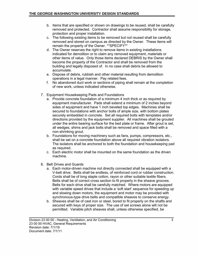
THE GEORGE WASHINGTON UNIVERSITY DESIGN STANDARDS
_________________________________________________________________________ Division 23 00 00 - Heating, Ventilation, and Air Conditioning 3 23 00 00 HVAC, General Requirements Revision date: 7/1/19 Document date: 7/1/11
b. Items that are specified or shown on drawings to be reused, shall be carefully removed and protected. Contractor shall assume responsibility for storage, protection and proper installation.
c. The following existing items to be removed but not reused shall be carefully removed and stored on campus as directed by the Owner. These items will remain the property of the Owner. **SPECIFY**
d. The Owner reserves the right to remove items in existing installations indicated for demolition or to claim any removed equipment, materials or other items of value. Only those items declared DEBRIS by the Owner shall become the property of the Contractor and shall be removed from the building and legally disposed of. In no case shall debris be allowed to accumulate.
e. Dispose of debris, rubbish and other material resulting from demolition operations in a legal manner. Pay related fees.
f. No abandoned duct work or sections of piping shall remain at the completion of new work, unless indicated otherwise.
7. Equipment Housekeeping Pads and Foundations
a. Provide concrete foundation of a minimum 4 inch thick or as required by equipment manufacturer. Pads shall extend a minimum of 2 inches beyond sides of equipment and have 1 inch beveled top edges. Machines shall be secured to foundations with anchor bolts of ample size, with bottom plates securely embedded in concrete. Set all required bolts with templates and/or directions provided by the equipment supplier. All machines shall be grouted under the entire bearing surface for the bed plate or frame. After grout is set, all wedges, shims and jack bolts shall be removed and space filled with a non-shrinking grout.
b. Foundations for moving machinery such as fans, pumps, compressors, etc., shall be set on a concrete foundation above all required vibration isolators. The isolators shall be anchored to both the foundation and housekeeping pad as required.
c. Each electric motor shall be mounted on the same foundation as the driven machine.
8. Belt Drives and Guards a. Each motor-driven machine not directly connected shall be equipped with a
V-belt drive. Belts shall be endless, of reinforced cord or rubber construction. Cords shall be of long staple cotton, rayon or other suitable textile fibers. Belts shall be of correct cross section to fit properly in the sheave grooves. Belts for each drive shall be carefully matched. Where motors are equipped with variable speed drives that include a ‘soft start’ sequence for speeding up and slowing down motors, the equipment and motor may be provided with synchronous-type drive belts and compatible sheaves to conserve energy.
b. Sheaves shall be of cast iron or steel, bored to fit properly on the shafts and secured with keys of proper size. The use of set screws alone will not be permitted. Variable pitch sheaves shall, unless otherwise specified, be

THE GEORGE WASHINGTON UNIVERSITY DESIGN STANDARDS
_________________________________________________________________________ Division 23 00 00 - Heating, Ventilation, and Air Conditioning 4 23 00 00 HVAC, General Requirements Revision date: 7/1/19 Document date: 7/1/11
selected so that the required RPM will be obtained with the sheave set approximately in mid-position.
c. Driving and driven shafts shall be set parallel and sheaves located so that corresponding grooves will be in the same plane. The driven sheave of each drive shall have the same groove spacing as the motor sheave.
d. The manufacturer's rating of each drive shall be at least 1.40 times the nameplate rating of the motor, with the proper allowance for arc of contact of less than 180 degrees. For variable pitch drives the horsepower rating of the drive shall be figured at the specified operating conditions. In no case shall drive for a motor larger than 1/2 HP have less than two belts.
e. Each belt drive shall be equipped with a metal guard which totally encloses all belts and sheaves and shall meet all applicable OSHA requirements. Guards shall be designed with adequate provision for movement of the motor required to adjust belt tension. Means shall also be provided to permit oiling, use of speed counters and other maintenance and testing operations with the guard in place.
9. Motor Starters, Generally
a. Each motor, except where provided with a variable speed drive, shall be equipped with a fully enclosed motor starter of proper design to meet the special requirements of the motor and drive. When a motor is furnished with a variable speed drive which provides comparable means of overcurrent protection, status indication, and building control interface to those specified elsewhere in this paragraph, then a separate motor starter does not need to be provided.
b. The starter shall be equipped with contacts to break each ungrounded line conductor to the motor. Thermal overcurrent devices shall be provided as required to open all contacts simultaneously. A suitable reset device for resetting overcurrents trip shall be provided. Starters shall be the standard manufactured product of General Electric, Eaton, Siemens or Square D.
c. Unless otherwise specified, starters shall be general purpose type mounted in steel cases equipped with suitable hinged doors arranged for padlocking. Each case shall be so arranged and designed that the entire starter can be readily removed and shall be of sufficient size to permit easy access for repair, replacement of parts and making of connections. Starters shall be arranged for wall, floor or panel mounting, as indicated on drawings or specified, and shall be complete with all necessary frames or supports.
d. All starters controlling automatic devices shall be provided with three position Hand-Off-Automatic transfer switch mounted on starter case and connected so that motor can be operated manually regardless of the position of the automatic control device. Transfer switch shall not be connected to supersede any safety device or safety interlock. Indicating pilot lights shall be included for all starters; Red, Running; Green, Off.
e. All multiple motorsets, such as booster pump packages, sump pumps, compressors, etc., shall be equipped with a control panel by the Contractor

THE GEORGE WASHINGTON UNIVERSITY DESIGN STANDARDS
_________________________________________________________________________ Division 23 00 00 - Heating, Ventilation, and Air Conditioning 5 23 00 00 HVAC, General Requirements Revision date: 7/1/19 Document date: 7/1/11
furnishing the equipment. The control panel shall contain the necessary starters, disconnect switches, automatic alternators, etc.
f. Provide starters with auxiliary contacts, for future connections to the University's energy management system, for the following equipment: air handling units, return/relief fans, exhaust fans, pumps, chillers, cooling towers.
10. Testing and Adjustments a. Testing and Balancing (TAB) Firm Qualifications: Projects 10,000 square
feet and greater shall have TAB services conducted. The TAB firm, certified by AABC, shall be procured and managed by GW. As directed by GW, the balancing scope shall be a separate design package provided by the MEP engineer. The base building documentation shall be fully coordinated with the balancing specifications.
b. Upon completion and prior to acceptance of the installation, capacity and general operating tests on the various building systems shall be conducted, by competent personnel, to demonstrate the specified capacities of the various pieces of equipment. Operating tests shall cover a period of not less than 8 hours for each system, and all tests shall be conducted at such times as the Owner may direct.
c. Equipment shall be adjusted so that it will perform as specified and required to give satisfactory operation. The Contractor shall subject the system to such additional tests as may be required by the Architect to properly demonstrate functional and operating efficiency. The entire temperature control system shall be adjusted and placed in operation by the manufacturer and all adjustment necessary to accomplish the specified results shall be made without cost to the Owner. Setting of valves, cocks, etc., shall be permanently marked so that they can be restored if disturbed at any time.
d. The Contractor shall furnish all necessary labor, fuel, instruments and equipment (such as smoke machines, gauges, air compressors, etc.) for the tests and shall meet all expense of said tests. If tests show that the work is in any way defective or at variance with the specification requirements the Contractor shall immediately make all changes necessary to correct the same and remedy defects to the satisfaction of the Architect. In the event the Contractor does not within a reasonable time remedy all the defects and make all changes required by the Architect to complete the work satisfactorily, the right is reserved to have defects remedied or changes made and to charge the cost of same against the account of the Contractor.
11. Cleaning
a. All piping shall be cleaned inside to remove dirt and loose scale, etc. All piping shall be flushed out prior to testing of equipment and all strainers shall be cleaned.
b. All ducts and apparatus casings shall be thoroughly cleaned before fans and filters are operated. After the equipment has been tested, all filters shall be

THE GEORGE WASHINGTON UNIVERSITY DESIGN STANDARDS
_________________________________________________________________________ Division 23 00 00 - Heating, Ventilation, and Air Conditioning 6 23 00 00 HVAC, General Requirements Revision date: 7/1/19 Document date: 7/1/11
renewed. The sets of filters indicated with the equipment shall not be used for testing, these filters shall be installed after the project has been accepted.
12. Painting
a. Air distribution devices including fan coil units, grilles, registers, diffusers, and louvers shall be factory-finished. Color shall be selected by the Architect.
b. Where factory finishes are provided on equipment and additional field painting is not required, all marred or damaged surfaces shall be touched-up or refinished as to leave a smooth, uniform finish at the time of acceptance.
c. Where visible, paint duct interior before installing grilles and registers. Paint one coat flat black. Concealed black steel pipe not to be insulated shall be painted with one coat of black asphaltum paint.
13. Operating Instructions
a. Upon completion of all work and of all tests, Contractor shall furnish the necessary skilled labor and helpers for operating all systems and equipment for a period of 1 day of 8 hours or as otherwise specified. During this period, instruct the Owner or his/her representative fully in the operation, adjustment, and maintenance of all mechanical and electrical equipment furnished or provided. Give at least 5 working days notice to the Owner in advance of this period.
b. Contractor shall furnish to the Architect instructions for operating and maintaining all mechanical and electrical systems and equipment included in the Contract. The operating and maintenance instructions shall conform to GW’s Facility Information Management (FIM) Standards. The instructions shall contain the following information:
i. Brief description of each system and components. ii. Starting and stopping procedures. iii. Special operating instructions. iv. Routine maintenance procedures. v. Manufacturer's printed operating and maintenance instructions, parts
list, illustrations and diagrams. vi. One copy of each wiring and control diagram. vii. One approved set of all shop drawings and Contractor's record
drawings. viii. System flow diagrams.
b. The Contractor shall submit one copy of the operation and maintenance manual to the Owner for approval at least thirty (30) days before date of final acceptance test of the system.
14. Refer to Specification Guidelines section 23 09 00, Instrumentation and Control for HVAC, for general information on control systems.

THE GEORGE WASHINGTON UNIVERSITY DESIGN STANDARDS
_________________________________________________________________________ Division 23 00 00 - Heating, Ventilation, and Air Conditioning 7 23 00 00 HVAC, General Requirements Revision date: 7/1/19 Document date: 7/1/11
15. Metering a. DC Water owns all of the water meters in DC, and configures them with an
automated meter reading (AMR) system to be read remotely. All new water meters should be set in such a way as to allow a radio-signal-sending device to be located near a building’s exterior wall or a manhole outside. GW Utilities and Engineering can help the construction team acquire the meter, strainer, and AMR unit from DC Water. For buildings with water-based cooling towers, three separate DC Water meters will be installed (or retained for existing buildings): main meter to building, cooling tower make-up, and cooling tower blowdown. Loudoun Water uses only two meters: main meter to building and cooling tower make-up.
b. GW’s general policy is that all on-campus, independently-operated venues (e.g. Starbucks’) are submetered for all utilities.
c. It is the intent of the Owner to have the primary utility meters for large buildings, and leased space tenant submeters, electronically metered and to have the metering data imported into the BAS and EMS. BAS/EMS should monitor natural gas and water demand (cfh, gpm) and accumulated consumption (ft3, gal) at the main building utility meters – and at any submeters in the building, such as for leased space tenants.
d. GW prefers that new venue meters be from the same manufacturers as existing venue meters. i. Natural Gas
a.) For natural gas, most existing venue meters include Onicon Insertion Model F-5200 meters with Model D-100 remote readouts while IMAC or utility-provided gas meters are also used.
ii. Water Use a.) For water, most existing venues meters are Metron-Farnier Model
50DL with TruRead remote readouts while some venues use Badger, Carlon, or Neptune water meters (suitable for separate hot and cold water delivery-temperature ranges).
iii. BTU Meters a.) For BTU meters, most existing venues use Onicon Model 10 BTU
meters while some use Siemens Sitrans F meters or a BTU calculation built into the BMS for HVAC chilled and hot water.
16. Identification
a. Valve tags: Attach brass tags with brass chains to all valves except valves at drain points, plumbing fixtures, hose bibbs and isolation valves at terminal devices. Tags shall be 2 inches in diameter, polished and lacquered, with 3/4 inch, black enamel filled, stamped designations as directed. Do not attach chains to valve wheels. Provide Owner one (1) framed copy of valve chart under glass, mounted on wall.
b. Ceiling identification tags: Equipment concealed above ceilings shall be clearly identified on the tee bar or access door directly below equipment. The identification tag shall be plastic laminate board engraved 1/4" high black
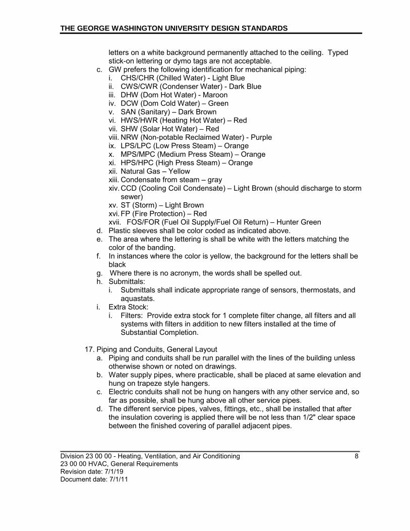
THE GEORGE WASHINGTON UNIVERSITY DESIGN STANDARDS
_________________________________________________________________________ Division 23 00 00 - Heating, Ventilation, and Air Conditioning 8 23 00 00 HVAC, General Requirements Revision date: 7/1/19 Document date: 7/1/11
letters on a white background permanently attached to the ceiling. Typed stick-on lettering or dymo tags are not acceptable.
c. GW prefers the following identification for mechanical piping: i. CHS/CHR (Chilled Water) - Light Blue ii. CWS/CWR (Condenser Water) - Dark Blue iii. DHW (Dom Hot Water) - Maroon iv. DCW (Dom Cold Water) – Green v. SAN (Sanitary) – Dark Brown vi. HWS/HWR (Heating Hot Water) – Red vii. SHW (Solar Hot Water) – Red viii. NRW (Non-potable Reclaimed Water) - Purple ix. LPS/LPC (Low Press Steam) – Orange x. MPS/MPC (Medium Press Steam) – Orange xi. HPS/HPC (High Press Steam) – Orange xii. Natural Gas – Yellow xiii. Condensate from steam – gray xiv. CCD (Cooling Coil Condensate) – Light Brown (should discharge to storm
sewer) xv. ST (Storm) – Light Brown xvi. FP (Fire Protection) – Red xvii. FOS/FOR (Fuel Oil Supply/Fuel Oil Return) – Hunter Green
d. Plastic sleeves shall be color coded as indicated above. e. The area where the lettering is shall be white with the letters matching the
color of the banding. f. In instances where the color is yellow, the background for the letters shall be
black g. Where there is no acronym, the words shall be spelled out. h. Submittals:
i. Submittals shall indicate appropriate range of sensors, thermostats, and aquastats.
i. Extra Stock: i. Filters: Provide extra stock for 1 complete filter change, all filters and all
systems with filters in addition to new filters installed at the time of Substantial Completion.
17. Piping and Conduits, General Layout a. Piping and conduits shall be run parallel with the lines of the building unless
otherwise shown or noted on drawings. b. Water supply pipes, where practicable, shall be placed at same elevation and
hung on trapeze style hangers. c. Electric conduits shall not be hung on hangers with any other service and, so
far as possible, shall be hung above all other service pipes. d. The different service pipes, valves, fittings, etc., shall be installed that after
the insulation covering is applied there will be not less than 1/2" clear space between the finished covering of parallel adjacent pipes.

THE GEORGE WASHINGTON UNIVERSITY DESIGN STANDARDS
_________________________________________________________________________ Division 23 00 00 - Heating, Ventilation, and Air Conditioning 9 23 00 00 HVAC, General Requirements Revision date: 7/1/19 Document date: 7/1/11
18. Pipe Sleeves a. The Contractor shall furnish and install sleeves in connection with all piping
passing through the walls, slabs, and building partitions. Sleeves shall be set in concrete construction before pouring, and in masonry during construction. The contractor shall be responsible for locating, setting and anchoring of sleeves in a substantial manner so that they will not become displaced.
b. Sleeves installed in a vertical position shall be constructed of 18 gauge galvanized steel. All sleeves installed in horizontal position and through beams shall be constructed of standard weight steel pipe. Annular space in pipe sleeves shall be tightly packed with mineral wool, blanket insulation or the approved flexible fireproof material.
c. Sleeves shall be of sufficient size to accommodate insulation and jacket covers.
d. Sleeves passing through floor slabs shall extend a minimum of 1 inch above the finished floor.
e. Sleeves passing through roof shall extend 12 inches above the finished roof or as required by roofing construction and/or details.
19. HVAC Pipe and Fittings:
a. Pipe joints shall be welded, soldered, or screwed, at all inaccessible locations, such as within shafts and chases, inside trenches and tunnels, and above hard ceilings.
b. In accessible locations, Victaulic mechanical pipe coupling systems may be used for heating, heat recovery, and chilled water pipe runs, except for systems where the temperature range of the conveyed fluid can vary by more than 60 degrees F.
c. Victaulic mechanical pipe coupling systems are not acceptable for use on condenser water systems.
d. ProPress/compression fittings shall only be used for repair. e. T-Drill method shall not be used.
20. HVAC Valves and Specialties
a. Valve charts shall include the valve manufacturer and model. Valve identification tags are not required on isolation and drain valves at fixtures and equipment.
b. Chain wheel operators are required on valves 3-inch and larger, located over 8 feet above the floor. For valves under 3-inch, chain wheels should only be provided if directed by GW.
c. Control valves shall have a pipe union at each connection end.
21. Hydronic Pumps, Heat Exchangers and Accessories a. On pump discharge side, preference is to install a combination balancing and
shut-off valve that is separate from the check valve. In tight locations, where approved by GW, triple duty valves may be installed.
b. Provide individual gauges in lieu of compound gauges at the strainer inlet, strainer outlet/pump suction, and pump discharge.

THE GEORGE WASHINGTON UNIVERSITY DESIGN STANDARDS
_________________________________________________________________________ Division 23 00 00 - Heating, Ventilation, and Air Conditioning 10 23 00 00 HVAC, General Requirements Revision date: 7/1/19 Document date: 7/1/11
22. Cooling Equipment a. General Refrigeration Requirements
i. CFCs/HCFCs shall not be utilized for refrigerants. ii. No SCBA (Self Contained Breathing Apparatus) gear shall be specified or
provided. Consult with GW Risk Management for any clarifications. b. Cooling Towers
i. Where an Electronic Level Sensor is installed for control of make-up to a Cooling Tower plant with multiple cells, a common water level sensor probe shall be installed in a standpipe connected to the equalizing line, with isolation valves arranged to allow operation for the operating cell(s) even when one cell is drained and shut down.
ii. Separate level sensors shall be provided in each cooling tower sump basin for monitoring of high and low water alarm levels.
iii. The make-up water line for cooling towers should be connected inside the building, in a heated area, to the common pipe that connects the cooling tower(s) to the suction side of the condenser water pump(s).
iv. Provide a sand filter(s) for cleaning condenser water in cooling tower systems. Centrifugal type solids separators are not acceptable. Sand filters should be furnished with pipe, controls, and fittings for automatic backwash cycles that regenerate the sand filter. Discharge lines shall terminate at adequately sized drain receptacles.
v. Cooling tower basins must have a traditional ball float mechanism installed to stop tower basin overflow conditions when they occur. Five-probe electronic level sensors on their own are insufficient. When installed, five-probe electronic level sensors should have all five probes connected and monitored by the building automation system, and not a subset of the five probes. The cooling tower basin level information should be visible for operator's to see on their control screens. Basin overflow conditions must trigger an alarm for the operators to respond to.
vi. The solenoid valve that controls the cooling tower blowdown discharge should be located near the system's water treatment testing station, and not in a different part of the building. Blowdown discharges should be taken from a tap on the return side of the water circulating to/from the cooling tower, and not directly from the cooling tower basin.
c. Cooling Coil Condensate i. Cooling coil condensate shall be piped to the cistern or to the cooling
tower make-up.
23. Hydronic Terminal Equipment a. Fan Coil Units:
i. Fan Coil Units (FCUs) are typically part of a local control zone where air and water flows are varied to maintain a space temperature setpoint. Ideally, FCUs are equipped with 2-way coil control valves. In buildings where 2-pipe FCUs are not equipped with control valves, occupants of the space should not have the ability to energize the fan. In such cases,

THE GEORGE WASHINGTON UNIVERSITY DESIGN STANDARDS
_________________________________________________________________________ Division 23 00 00 - Heating, Ventilation, and Air Conditioning 11 23 00 00 HVAC, General Requirements Revision date: 7/1/19 Document date: 7/1/11
the fan must cycle on and off to maintain temperature in the space. Refer to Section 23 09 00 for standards on local zone control, such as room thermostats.
ii. In a two-pipe fan coil system, as typically installed in residence halls, a means must be provided to automatically switch the thermostat between heating and cooling mode. a.) When the individual fan coil unit controls are part of a Building
Automation System (BAS) control network, then the changeover between heating and cooling modes can be accomplished by a global command over the building network.
b.) When the FCU is not controlled through a BAS, an aquastat with a sensor on the supply pipe shall be used to switch the FCU temperature controls between heating and cooling modes of operation.
iii. Water detectors that shut down the fan should be installed in the drain pan. Detector should not be an electronic probe type. GW HVAC Maintenance prefers sensors using a float switch.
iv. Where the only access to a fan coil unit is through a return louver or equipment panel, the louver or panel should be mounted with hinges on a stiff frame.
v. Room thermostats should be located near the return air path in residential suites.
24. Cleaning and Flushing: The process of cleaning and flushing the interior of new
piping systems will generate wastewater that must be disposed of in accordance with Title 21 of the DC Municipal Regulations. Besides compliance with DCMR Title 21, the following practices should be employed: a. Flushing water should be disposed of into the sanitary sewer system
(assuming the wastewater meets the DCMR and DCWASA standards for pH, metals, etc.)
b. Flushing water should be discharged through a strainer. Sludge and debris from the strainer should be treated as solid waste for disposal in a landfill.
c. To avoid the discharge of chemicals into the Potomac River caused by sewer overflows during wet weather; cleaning and flushing operations should be conducted during periods of dry weather.
25. Combustion Equipment
a. Combustion Equipment, such as boilers, water heaters, and steam humidifiers, shall be located in rooms adjoining a shaft that rises straight up through the building, adequately sized to hold chimney flues that will convey combustion gasses above the roof to atmosphere, in accordance with the building codes.
b. Condensing Boilers and Water Heaters i. A 100 MBH input condensing water heater or boiler can produce 3.5 liters
per hour of condensate, with an acidic pH around 3. Condensate must be

THE GEORGE WASHINGTON UNIVERSITY DESIGN STANDARDS
_________________________________________________________________________ Division 23 00 00 - Heating, Ventilation, and Air Conditioning 12 23 00 00 HVAC, General Requirements Revision date: 7/1/19 Document date: 7/1/11
collected and neutralized before discharge into the sanitary sewer (or to a pump basin).
ii. Flues must be corrosion-resistant and installed with a 2 percent slope back towards the boiler or a drain fittings. A U-trap is required on boiler and flue drains - follow manufacturer's instructions.
iii. Drain lines need to be acid resistant - copper and mild steel are not acceptable, stainless steel is. Pipe material selection should consider whether the installation location requires a ASTM E 84, 25/50 flame spread/smoke developed rating. Most plastic pipe can not comply unless enclosed in a fire wrap.
iv. "FlowGuard Gold", CPVC pipe and fittings, up to 2 inch diameter, have been successfully tested in accordance with ASTM E 84, both while filled with water or dry, and found compliant with the requirements of the IMC and NFPA 90A.
26. Air Distribution
a. Ductwork: i. Design plans and specifications shall indicate the pressure class and
sealant type for all ductwork on the project. ii. All exhaust ductwork installed in inaccessible locations (such as shafts,
tunnels or direct-buried), and supply ducts over 2-inch pressure class, shall be tested before insulation and concealment. a.) Design documents shall specify test pressures and leakage class. b.) The mechanical contractor shall test, and an Owner’s Representative
shall have the option to witness, 100% of the inaccessible exhaust ducts, and the primary supply ducts up to the air control valve. The Commissioning Agent (as one of the Owner’s Representatives) shall witness a sample of any ductwork testing and cleaning procedures, sufficient to be confident that proper procedures were followed. Tertiary and/or specialty supply and exhaust duct systems shall be tested as required by Owner.
c.) Test sections should not exceed 150 LF in length and should include any dampers (volume control, smoke, fire) required by the contract documents.
d.) Mechanical contractor shall submit a duct testing plan 30 days before the onset of testing, indicating the phasing and extent of test sections.
e.) Mechanical contractor shall be responsible for calculating the surface area of test sections and the allowable leakage. Calculation shall be turned over with the test results to the Owner’s representative.
iii. Longitudinal duct seams shall be Pittsburgh Lock with sealant. Button Punch Snap Lock seams are not acceptable.
iv. Transverse joints for ducts whose smallest dimension is 8-inches or greater should be flanged and gasketed assemblies. On smaller ducts, drive slip joints may be used, but joints shall be sealed with a two-part tape and mastic system.

THE GEORGE WASHINGTON UNIVERSITY DESIGN STANDARDS
_________________________________________________________________________ Division 23 00 00 - Heating, Ventilation, and Air Conditioning 13 23 00 00 HVAC, General Requirements Revision date: 7/1/19 Document date: 7/1/11
b. Ductwork Accessories and Air Specialty Accessory Items: i. Ductwork accessories and air specialty accessory items including sound-
lined ductwork, sound attenuators, all duct fittings, VAV boxes, duct heaters, reheat boxes, fan boxes, air valves, and PIM modules shall meet the same pressure and seal class construction type as the adjacent ductwork.
c. Exhaust Fans: i. Nutone exhaust fans are not acceptable. ii. Spaces with microwave ovens and/or cooking activity such as pantries
should be exhausted to the outdoors. d. Diffusers:
i. Perforated face panel diffusers shall not be specified.
27. Building Control Systems a. General
i. GW Nomenclature BAS – Building Automation System – refers to the software and hardware devices used to control operation of equipment and processes within the building, including, but not limited to, HVAC, mechanical, lighting, power, plumbing, life safety, access, security, and audio-visual systems.
Building Controller panel (panels) – Building based computing system interfacing with and executing programmed tasks within the electrical and mechanical facilities elements of the building. EMS – Energy Management System – refers to the software and hardware devices used for centralized supervisory control, data acquisition, and alarm monitoring of BAS systems in particular GW-controlled buildings. While multiple EMSs are in use now, upon consolidation GW hopes to utilize only one, Enterprise-Level, EMS in the future – the Schneider Electric Vijeo Citect system, which GW refers to as its “SCADA” system. SCADA is an acronym borrowed from utility and industrial control that stands for Supervisory Control and Data Acquisition.
ii. Design Documents
a.) Contract documents should indicate control sequences and schematic diagrams on the plans, rather than in the specifications.
b.) Design plans should also clearly distinguish those points of control that can be monitored and manipulated through the campus EMS. Provide a schedule on the plans of EMS points that indicates:
a) Point name b) Sensor type c) Binary/Analog, Input/Output d) Alarm Limits e) Alarm Message
THE GEORGE WASHINGTON UNIVERSITY DESIGN STANDARDS
_________________________________________________________________________ Division 23 00 00 - Heating, Ventilation, and Air Conditioning 14 23 00 00 HVAC, General Requirements Revision date: 7/1/19 Document date: 7/1/11
f) Parameters for Totalization or Trending Software Control Interlocks
iii. Control Wiring
a.) Junction Boxes shall be marked on the side and cover as “BAS – Building Automation System”
b.) Cables within each junction box shall be tagged with their circuit and function.
END OF SECTION

Division 23 – Heating, Ventilation and Air Conditioning 23 09 00 Instrumentation and Control for Building Automation and Metering Systems Revision date: 10/1/19 Document date: 9/22/09
1
23 09 00 INSTRUMENTATION AND CONTROL FOR BUILDING AUTOMATION AND METERING SYSTEMS
A. SUMMARY
This section contains design standards for building automation systems with integrated energy and water metering. Refer to space standards for additional information. This document contains the specification and input/output summaries for the Building Automation System (BAS) at GWU. The system architecture shall utilize intelligent distributed control modules, located at each site, which communicate over a local controller network. The BAS shall provide Direct Digital Control (DDC).This BAS for the air conditioning, heating and ventilating systems shall interface with other microprocessor based building subsystems as specified.
B. GENERAL
Energy efficiency and the student experience are among the highest priorities at the University. Consultants shall always strive to achieve the highest energy efficiency combined with the ultimate student experience possible within the parameters of campus security, project budget and function. Selection of HVAC systems shall always reflect this priority. Spaces such as dormitory rooms and private offices are typically provided with individual thermostats for occupant comfort. Additionally, consultant shall give strong consideration to providing occupancy sensor-based HVAC controls. Consultant shall pursue systems that allow setback thresholds when the space is not occupied, with full comfort levels achieved upon occupancy. If it is possible and cost effective to coordinate this occupancy sensor approach with that for lighting controls, that is also encouraged.
Beginning January 2018, The GW Building Automation Systems will consist of an open architecture that utilizes integral ANSI / ASHRAE™ Standard 135- Latest Edition, BACnet functionality to assure interoperability between all system components. It is the intent of this document that all control and monitoring data points, including those at the Application and Field Bus Level, be exposed through the Ethernet Enterprise Network Level and normalized to BACnet over IP.
THE GEORGE WASHINGTON UNIVERSITY DESIGN STANDARDS
This document provides design standards only, and is not intended for use, in whole or in part, as a specification. Consultants referencing this information must always meet all applicable state and local building codes as well as all barrier free design requirements. Consultants must also refer to the entire set of Design Standards for additional information. Refer questions and comments regarding the content and use of this document to the George Washington University Project Manager.

Division 23 – Heating, Ventilation and Air Conditioning 23 09 00 Instrumentation and Control for Building Automation and Metering Systems Revision date: 10/1/19 Document date: 9/22/09
2
THE GEORGE WASHINGTON UNIVERSITY DESIGN STANDARDS
Apogee/Insight (in many buildings), and Schneider Electric’s Vijeo Citect (in several buildings) and also EcoStruxure Building Operator (in one building). Siemens has begun phasing out its Insight software to eventually be replaced by Desigo CC, so GW has also begun this same transition.
In August 2017, GW completed the consolidation of its network infrastructure used to support these systems into one scalable and secure network using BACnet. All of the systems described above now operate on a single, private network known as the Facilities virtual routing and forwarding (VRF) network on all three campuses. Proprietary BAS software is no longer in use. Each system, and Vijeo Citect in particular, monitors energy and water usage in many buildings, and exports this information to a public Internet site and to on-campus kiosks for community use. Existing campus kiosks have been provided by Lucid Designs. BAS data are also securely exported to several other equipment vendors for purposes of allowing them to remotely monitor the operation of their equipment located on GW’s campuses. The consultant shall coordinate with one of the incumbent BAS Vendors, such as the Schneider Electric Factory Branch as basis of design, to ensure GW BAS Standards are properly communicated and maintained within the project design.
ALL aspects of the design, installation and implementation of any GWU building automation control project requires the approval of the GWU’s Building Automation Group before the BAS installation can proceed.
CONTROL SYSTEMS PART 0 – GENERAL STANDARDS OF DESIGN
A. GW NOMENCLATURE
BAS – Building Automation System – refers to the software and hardware devices used to control operation of equipment and processes within the building, including, but not limited to, HVAC, mechanical, lighting, power, plumbing, life safety, access, security, and audio-visual systems.
Building Controller panel (panels) – Building based computing system interfacing with and executing programmed tasks within the electrical and mechanical facilities elements of the building.
EMS – Energy Management System – refers to the software and hardware devices used for centralized supervisory control, data acquisition, and alarm monitoring of BAS systems in particular GW-controlled buildings. Multiple EMSs are now in use, as furnished and supported by Siemens, Johnson Controls, and Schneider Electric. The Schneider Electric “Vijeo Citect” system is referred to by GWU as its SCADA system. SCADA is an acronym borrowed from utility and industrial control that stands for Supervisory Control and Data Acquisition.

Division 23 – Heating, Ventilation and Air Conditioning 23 09 00 Instrumentation and Control for Building Automation and Metering Systems Revision date: 10/1/19 Document date: 9/22/09
3
THE GEORGE WASHINGTON UNIVERSITY DESIGN STANDARDS
B. WARRANTY
1. Building control systems shall be warrantied for a minimum of two years
past the date of building commissioning and final acceptance testing.
C. OWNER INTENT
1. It is the intent of the Owner to interconnect each of its building automation
systems into the Facilities VRF without the need for proprietary software, interface devices, or passwords not in possession of the Owner. GW will pull data from new equipment into an existing system for operator interface, alarm reporting, and data capture and analysis.
2. It is the intent of the Owner to have the primary utility meters for large buildings, and leased space tenant sub meters, electronically metered and to have the metering data imported into the BAS and into the EMS. For example, the main building utility meters - electric, natural gas, and water meters in a building would be connected to the BAS/EMS; along with the meters for leased space tenants within the building. For electric meters, a second goal is to design the electrical distribution system (switchgear and breaker panels) so that sub meters can separately measure the mechanical systems, lighting, and plug loads. In buildings with cisterns for storm water reuse, additional meters may be needed to track the amount of storm water reused.
3. It is the intent of the Owner to ensure that energy utilization is part of the decision-making process of the building operators. For example, if the building electric meter reaches a new high demand level, the BAS/EMS notifies the operator to take action to investigate and reduce the load.
4. GW’s large buildings participate in electrical demand response events called by the electric grid operator, particularly in summer but potentially year round. New, large buildings should include one or more sequences of executable operations within the BAS/EMS designed to reduce a known electrical demand load and the building systems response in terms of reduced demand (kW) should be visible to the operator. This response could include for example lowering pump or fan output, cycling equipment, forcing some equipment off, or altering the output of the cogeneration plant. This response cannot be met by running on-site emergency generators due to environmental permitting restrictions.
D. SCOPE OF WORK
1. Provide building level control systems capable of integrating into GW’s Facilities
VRF network environment. The building level panels are to function over an IP based network with all points addressable and modifiable from any operator work station (OWS) or from a master BC or device-level connection points using a portable computer without the need for proprietary system passwords or interface devices. BAS shall be fully expandable with addition of hardware and/or software. For major BAS Software upgrades, the BAS Software must be submitted to GWU Division of IT for a security assessment prior to connection to the VRF. GWU Division of IT is responsible for coordinating this effort.

Division 23 – Heating, Ventilation and Air Conditioning 23 09 00 Instrumentation and Control for Building Automation and Metering Systems Revision date: 10/1/19 Document date: 9/22/09
4
THE GEORGE WASHINGTON UNIVERSITY DESIGN STANDARDS
2. New building construction and major renovations - the exact specification
of the University’s future EMS open architecture and its interface with the various BASs is an evolving process. At this point, it can be stated that the higher-level building network control panels, and application controllers for major systems and equipment such as condenser water, chilled water, steam or heating water, large air handling units, and energy recovery ventilators, should support Modbus SNMP or BACnet type controllers communicating across an IP based network (using IPv4 or IPV6 network addressing scheme), and the Owner’s operators should be trained on how to modify or add controllers to this ‘building level’ network.
3. Minor renovation work will usually involve modification of existing legacy BAS systems only into the system already in use in a particular building
4. All objects shall be exposed as BACnet Objects, with full Functional Profile information to facilitate BACnet IP communication between multiple vendors
5. All Integration gateway modules to interface with 3rd party equipment as specified by the owner through BACnet IP, or MSTP
6. All new installations shall be de-scoped and pre- approved by the Building Automation Group. The impact on the system must be evaluated by the Building Automation Group before any new equipment is merged with the existing system. All controllers and hardware shall be a part of the larger University Building Automation System.
7. All BACnet Instance ID’s and Network ID’s shall be reported in a vendor specific master spreadsheet form to GWU Building Automation Group for each project.
8. Protecting the stability and integrity of the University’s Building Automation System is critical and a primary function of the Building Automation Group. Therefore, all demolition of existing controllers shall be overseen by the GWU Automation Group, and may in some cases be performed by the contracting vendor with approval from the Building Automation Group.
E. DESIGN DOCUMENT STANDARDS
1. Construction drawings shall include: a. Schematic diagrams of building systems showing the arrangement of energy
and material flows, location of sensors and control devices, and major pieces of equipment. Including Electric Sub Meters and occupancy sensors that are to be provided under the BAS Scope of Work
b. Sequences of operation for building systems and equipment, preferably on the same drawing as the system schematic.
c. Schedules of points for monitoring and control, along with abbreviated and expanded identifiers, instrumentation type, alarm limits, control interlocks with
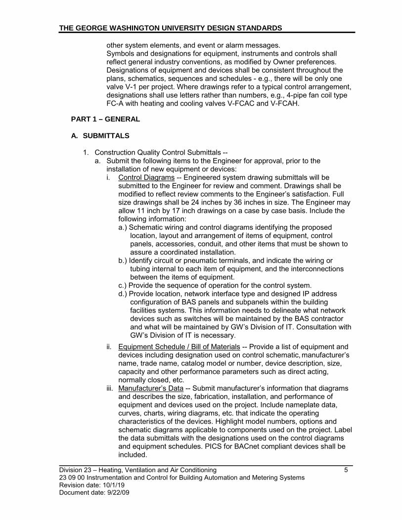
Division 23 – Heating, Ventilation and Air Conditioning 23 09 00 Instrumentation and Control for Building Automation and Metering Systems Revision date: 10/1/19 Document date: 9/22/09
5
THE GEORGE WASHINGTON UNIVERSITY DESIGN STANDARDS
other system elements, and event or alarm messages. Symbols and designations for equipment, instruments and controls shall reflect general industry conventions, as modified by Owner preferences. Designations of equipment and devices shall be consistent throughout the plans, schematics, sequences and schedules - e.g., there will be only one valve V-1 per project. Where drawings refer to a typical control arrangement, designations shall use letters rather than numbers, e.g., 4-pipe fan coil type FC-A with heating and cooling valves V-FCAC and V-FCAH.
PART 1 – GENERAL
A. SUBMITTALS
1. Construction Quality Control Submittals --
a. Submit the following items to the Engineer for approval, prior to the installation of new equipment or devices: i. Control Diagrams -- Engineered system drawing submittals will be
submitted to the Engineer for review and comment. Drawings shall be modified to reflect review comments to the Engineer’s satisfaction. Full size drawings shall be 24 inches by 36 inches in size. The Engineer may allow 11 inch by 17 inch drawings on a case by case basis. Include the following information: a.) Schematic wiring and control diagrams identifying the proposed
location, layout and arrangement of items of equipment, control panels, accessories, conduit, and other items that must be shown to assure a coordinated installation.
b.) Identify circuit or pneumatic terminals, and indicate the wiring or tubing internal to each item of equipment, and the interconnections between the items of equipment.
c.) Provide the sequence of operation for the control system. d.) Provide location, network interface type and designed IP address
configuration of BAS panels and subpanels within the building facilities systems. This information needs to delineate what network devices such as switches will be maintained by the BAS contractor and what will be maintained by GW’s Division of IT. Consultation with GW’s Division of IT is necessary.
ii. Equipment Schedule / Bill of Materials -- Provide a list of equipment and devices including designation used on control schematic, manufacturer’s name, trade name, catalog model or number, device description, size, capacity and other performance parameters such as direct acting, normally closed, etc.
iii. Manufacturer’s Data -- Submit manufacturer’s information that diagrams and describes the size, fabrication, installation, and performance of equipment and devices used on the project. Include nameplate data, curves, charts, wiring diagrams, etc. that indicate the operating characteristics of the devices. Highlight model numbers, options and schematic diagrams applicable to components used on the project. Label the data submittals with the designations used on the control diagrams and equipment schedules. PICS for BACnet compliant devices shall be included.

Division 23 – Heating, Ventilation and Air Conditioning 23 09 00 Instrumentation and Control for Building Automation and Metering Systems Revision date: 10/1/19 Document date: 9/22/09
6
THE GEORGE WASHINGTON UNIVERSITY DESIGN STANDARDS
iv. Report Formats – Samples of the reports that will be automatically
generated, as required in the specifications. v. System Graphics -- Display for use at the user interface. Equipment
graphics shall show a flow diagram of the equipment, with location of sensors and control devices. Provide button links to related equipment and building system graphics, trend logs, and reports. For new construction, GW expects all new user-interface graphics to be added to the relevant BAS. Each BAS should use consistent symbols for each type of equipment depicted for common types of HVAC equipment like pumps and temperature sensors whereas larger equipment such as boilers can vary from one OWS screen to another to reflect unique aspects of the boiler installed at each site. Schneider Electric has a specification outlining the acceptable graphic symbols and conventions that it will use within GW’s Vijeo Citect EMS.
vi. Closeout Submittals – Submit copies of the Operation and Maintenance Manual for the Engineer’s review and approval, and to the Owner’s personnel thirty days prior to system acceptance testing. After acceptance testing of the system, and submittal approval by the Engineer, provide of as-built control drawings and the Operation and Maintenance Manuals, along with graphic files, to the Owner prior to contract closeout. Comply with current GW standard for archival documents.
vii. As-Built Control Diagrams -- Provide approved, final engineered system drawings in hard copy and electronic format per GW ‘FIM Procedures Manual’. System information shall be provided in operation and maintenance manuals. One copy of each applicable drawing, laminated in clear heavy plastic, shall be located at each local control panel. Drawings and diagrams shall include the following: a.) - Location and designation of the system and local control panel to
which the drawing applies. b.) - Numeric designation of equipment device and panel terminals, wiring
circuits and tubing. Include distribution panel and circuit number of the power sources of control circuits.
c.) - Deviations from specified settings or operations necessitated during system start-up and adjustment.
viii. Operation and Maintenance Manual – O&M information shall include at minimum, all record submittals. Information shall be clearly organized and tagged with information on the name and location of the project, the name of the Contractor, the project contract number, and the following information: a.) - Name, address, telephone number, and contact reference for each
subcontractor installing equipment, and for local representatives for each item of equipment.
b.) - Written description of the control sequences including procedures for start-up, operation, and shut-down.
c.) - Description of the function of each device or equipment item; along with performance data, parts list, installation instructions, test and calibration procedures, and safety precautions. Parts list shall indicate a source of supply, recommended spare parts and inventory levels, and the local area service organization(s).

Division 23 – Heating, Ventilation and Air Conditioning 23 09 00 Instrumentation and Control for Building Automation and Metering Systems Revision date: 10/1/19 Document date: 9/22/09
7
THE GEORGE WASHINGTON UNIVERSITY DESIGN STANDARDS
d.) - Maintenance instructions, including a lubrication schedule indicating
type, grade, temperature range, and frequency.
PART 2 – PRODUCTS AND MATERIALS
A. DEFINITIONS
It is preferred that the use of ASCs be minimized on new construction/major renovation projects. AACs are preferred over ASCs.
COS – Change of State – When a point is designated as COS, the control system shall annunciate at the OWS, and record to system memory, the time and change in the binary status of a piece of equipment or control device, e.g., a valve opening or closing, or a fan starting or stopping.
Occupant Override – a control option that allows a building occupant to override the programmed HVAC schedule for a programmed period of time. When the override time expires, the control zone will return to its unoccupied state.
Occupant Set point Adjustment – a control option that allows building occupants to adjust the heating and cooling set points of a zone – within limits programmed into the control system. Typically the user interface is built in to the zone sensor.
OWS – Operator Work Station – a fixed terminal, with or without a hard copy printer, provided either as part of a BAS or EMS. Note that any new operator work stations must meet the latest performance standard in force by GW’s Division of Information Technology.
S/S – Start/Stop Point – shall provide the capability of energizing/de-energizing motors, or activating/de-activating control subroutines, either through a manual command from an OWS, or from a programmed operating schedule. Control systems shall have the capacity to provide, for every designated start/stop point, a unique schedule for every day of the week, and a holiday schedule to take effect automatically for up to 20 days out of the year. Every start/stop point shall be accompanied by status monitoring that will annunciate an alarm at the OWS and record to system memory, any event in which the actual operating status of the equipment or system differs from the intent of the manual or programmed command.
SCADA – Supervisory Control and Data Acquisition.
ModBus - is a serial communications protocol originally published by Modicon (now Schneider Electric) in 1979 for use with its programmable logic controllers (PLCs). Simple and robust, it has since become a de facto standard communication protocol, and it is now a commonly available means of connecting industrial electronic devices.
Advanced Application Controller (AAC) - A device with limited resources relative to the Building Controller (BC). It may support a level of programming and may also be intended for application specific applications.

Division 23 – Heating, Ventilation and Air Conditioning 23 09 00 Instrumentation and Control for Building Automation and Metering Systems Revision date: 10/1/19 Document date: 9/22/09
8
THE GEORGE WASHINGTON UNIVERSITY DESIGN STANDARDS
Application Protocol Data Unit (APDU) - A unit of data specified in an application protocol and consisting of application protocol control information and possible application user data (ISO 9545).
Application Specific Controller (ASC) - A device with limited resources relative to the Advanced Application Controller (AAC). It may support a level of programming and may also be intended for application-specific applications.
BACnet/BACnet Standard - BACnet communication requirements as defined by ASHRAE/ANSI 135 and all current addenda and annexes. It is preferred to minimize the use of BACnet MS/TP and instead utilize a BACnet IP Fieldbus
BACnet Interoperability Building Blocks (BIBB) - BIBB defines a small portion of BACnet functionality that is needed to perform a particular task. BIBBS are combined to build the BACnet functional requirements for a device in a Specification.
Binding - In the general sense, binding refers to the associations or mappings of the sources network variable and their intended or required destinations.
Building Automation System (BAS) - The entire integrated management, monitoring, and control system.
Building Controller (BC) - A fully programmable device capable of carrying out a number of tasks including control and monitoring via direct digital control (DDC) of specific systems, acting as a communications router between the LAN backbone and sub-LANs, and data storage for trend information, time schedules, and alarm data.
Change of Value (COV) - An event that occurs when a measured or calculated analog value changes by a predefined amount (ASHRAE/ANSI 135).
Client - A device that is the requestor of services from a server. A client device makes requests of and receives responses from a server device.
Continuous Monitoring - A sampling and recording of a variable based on time or change of state (e.g. trending an analog value, monitoring a binary change of state).
Controller or Control Unit (CU) - Intelligent stand-alone control panel. Controller is a generic reference and shall include BCs, AACs, and ASCs as appropriate.
Control Systems Server (CSS) - This shall be a computer (or computers) that maintains the systems configuration and programming database. This may double as an operator workstation.
Direct Digital Control (DDC) - Microprocessor-based control including Analog/Digital conversion and program logic.
Functional Profile - A collection of variables required to define key parameters for a standard application. For the HVAC industry, this would include applications like VAV terminal units, fan coil units, etc.
Division 23 – Heating, Ventilation and Air Conditioning 23 09 00 Instrumentation and Control for Building Automation and Metering Systems Revision date: 10/1/19 Document date: 9/22/09
9
THE GEORGE WASHINGTON UNIVERSITY DESIGN STANDARDS
Gateway (GTWY) - A device, which contains two or more dissimilar networks/protocols, permitting information exchange between them (ASHRAE/ANSI135-(use the most current version)
Hand Held Device (HHD) - Manufacturer’s microprocessor based device for direct connection to a Controller.
IT LAN - Reference to the facility’s Information Technology network, used for normal business-related e-mail and Internet communication.
LAN Interface Device (LANID) - Device or function used to facilitate communication and sharing of data throughout the BAS.
Local Area Network (LAN) - General term for a network segment within the architecture. Various types and functions of LANs are defined herein.
Local Supervisory LAN - Ethernet-based LAN connecting Primary Controller LANs with each other and OWSs and CSSs and the LAN to which the GEMnet will be interfaced. See System Architecture herein.
Master-Slave/Token Passing (MS/TP) - Data link protocol as defined by the BACnet standard (ASHRAE/ANSI 135).
WAN - Internet-based network connecting multiple facilities with a central data warehouse and server, accessible via standard web-browser.
Open Database Connectivity (ODBC) - An open standard application-programming interface (API) for accessing a database developed. ODBC compliant systems make it possible to access any data from any application, regardless of which database management system (DBMS) is handling the data.
Operator Interface (OI) - A device used by the operator to manage the BAS including OWSs, POTs, and HHDs.
Operator Workstation (OWS) - The user’s interface with the BAS system. As the BAS network devices are stand-alone, the OWS is not required for communications to occur.
Point-to-Point (PTP) - Serial communication as defined in the BACnet standard.
Portable Operators Terminal (POT) - Laptop PC or tablet used both for direct connection to a controller and/or for remote connections.
Protocol Implementation Conformance Statement (PICS) - A written document, created by the manufacturer of a device, which identifies the particular options specified by BACnet that are implemented in the device (ASHRAE/ANSI 135).
Primary Controlling LAN - High speed, peer-to-peer controller LAN connecting BCs and optionally AACs and ASCs. Refer to System Architecture herein.
Router - A device that connects two or more networks at the network layer.

Division 23 – Heating, Ventilation and Air Conditioning 23 09 00 Instrumentation and Control for Building Automation and Metering Systems Revision date: 10/1/19 Document date: 9/22/09
10
THE GEORGE WASHINGTON UNIVERSITY DESIGN STANDARDS
Secondary Controlling LAN - LAN connecting AACs and ASCs, generally lower speed and less reliable than the Primary Controlling LAN. Refer to System Architecture herein
B. NETWORKING COMMUNICATIONS
1. The design of the BAS shall network OWS and stand-alone controllers. The
network architecture shall consist of multiple levels for communication efficiency – a campus-wide EMS Ethernet network based on TCP/IP protocol; a high performance peer-to-peer building level network(s); and floor level local area networks.
2. The network interface of BAS shall be Ethernet interface capable of communicating across a wired, IP based network.
3. Access to the network from operator interface devices shall be totally transparent to the user when accessing data or developing control programs. Users shall have the ability to access all point status and application report data, and to execute control functions, for any and all other devices via the peer-to-peer network.
4. The design of the BAS shall allow for the co-existence of new DDC Controllers with existing DDCCs, without the use of gateways or protocol convertors.
5. The system shall support integration of third party systems (such as fire alarm, security, lighting, chillers) via panel mounted, open protocol processors. Such processors shall exchange data between the two systems, maintaining full BAS functionality across the exchange.
6. The peer-to-peer Building Level Network shall use TCP/IP over Ethernet. All devices must: a. Auto-sense 10/100/1000 Mbps networks. b. Must be configured with a Static IP Address. IP address can only be
obtained through the GWU automation group after receiving the MAC address for the device.
c. Resolve name to IP Addresses for devices using a Domain Name Service (DNS) Server on the Ethernet network.
d. If a BACNet device is being added, it should be capable of supporting BACNet Broadcast Management software and act as the BBM for the subnet. If a BBM Device (BBMD) already exists on the network subnet, the BAS should be capable of utilizing the current BBMD for all network communications.
e. Vendor shall provide list of TCP or UDP ports required for communication across the network.
7. The Fieldbus Level Network shall primarily be BACnet IP. BACnet MS/TP is acceptable, but not preferred: a. BACnet IP Fieldbus requirements: The system shall consist of one or more
BACnet/IP field buses managed by the BC. The field bus layer shall consist of up to 50 IP AACs in daisy chain topology, or 39 if using RSTP, per layer, with a max of 5 sub networks in daisy chain for a total of 250 AACss or 6 sub networks in RSTP for a total of 234 AACs.

Division 23 – Heating, Ventilation and Air Conditioning 23 09 00 Instrumentation and Control for Building Automation and Metering Systems Revision date: 10/1/19 Document date: 9/22/09
11
THE GEORGE WASHINGTON UNIVERSITY DESIGN STANDARDS
C. HVAC CONTROL ZONES
1. General Designers must seek to achieve an efficient balance between controls and cost. In office spaces workstations are often grouped together into a common control zone. Generally, humidity control is only attempted in special cases such as when a research program, or a collection of materials, requires a stable environment. Demand controlled ventilation is often provided to high occupancy spaces, especially when the population varies through the day. The partition of the project area into control zones with specific environmental criteria needs to be approved by the Owner at an early basis of design stage. It is encouraged to for the consultant to coordinate with one of the incumbent BAS Vendors, such as the Schneider Electric Factory Branch as basis of design, to assist in the efficient balance between controls and cost. 2. Intermittent versus Prolonged Occupancy Spaces
a. Most control schemes loosen the environmental criteria during unoccupied periods. Designers shall work with the Owner during the basis of design stage to identify the expected nature of occupancy within a control zone.
b. Areas such as classrooms, conference rooms, circulation and gathering space, lobbies and other more public areas can be considered as intermittent occupancies, and the control schemes are usually programmed to maintain different setpoints during occupied and unoccupied periods. At a minimum, occupancy is determined by a time schedule, but savings can often be obtained by linking the HVAC controls with the lighting occupancy sensors via BACnet IP interface between systems.
c. Areas such as dwelling units and office workstations are considered as prolonged occupancies. In these spaces, the occupants should be given more control over their environment. The Owner needs to approve whether occupants who choose to work in a space outside of normal operating hours should be given the ability to override setpoints and cause the startup of central HVAC equipment such as Air Handling Units and Circulating Pumps.
3. Temperature Control
a. Control Zones with Intermittent Occupancy are usually provided with a BAS controller whose set points cannot be changed by the occupants. Set points, setbacks, dead bands and other parameters are selected through the BAS. Space temperatures are measured either with wall sensors or return air sensors.
b. Control Zones with Prolonged Occupancy shall be provided with a user interface, such as a wall thermostat. Temperature set points shall be adjustable within a limited range of 69 to 75 degrees F. The BAS controls shall have a dead band of plus or minus 3 degrees F. around the 72 degree F set point, during which neither heating nor cooling is provided. When fan coil units are located in the control zone, provide the occupants access to a fan switch – ON-OFF-AUTO in dwelling units; OFF-AUTO in office space.

Division 23 – Heating, Ventilation and Air Conditioning 23 09 00 Instrumentation and Control for Building Automation and Metering Systems Revision date: 10/1/19 Document date: 9/22/09
12
THE GEORGE WASHINGTON UNIVERSITY DESIGN STANDARDS
4. Sensors and Guards a. Sensors (for specialty applications where the program requires close control
of temperature and humidity such as museums and labs): i. Approved manufacturer, no exceptions:
a.) BAPI (Building Automation Products, Inc.) b. Guards: Thermostats located in high traffic areas in all building types shall
have a guard to prevent tampering, physical damage and unauthorized use. i. Approved product and manufacturer, no exceptions:
a.) BAPI-Guard by BAPI
5. Use of Therma-Fuser for Private Office Temperature Control a. The cost of providing an independently controlled, heating and cooling
system for individual private offices is often prohibitively expensive whether it involves a VAV reheat box, fan coil unit, or chilled-heated beam. Often, the budget only allows for grouping together private offices into a single control zone with a thermostat in one office controlling the group.
b. A more cost effective solution to the problem of providing individual temperature control in private offices is the use of thermally-actuated, variable volume diffusers. GW strongly prefers to use “Therma-Fuser” TF-C or TF-HC models, as manufactured by Accutherm. In lieu of “Pressure Independence Modules” (PIMs) as they are referred to by some manufacturers, 100% shut-off VAV boxes shall be used to control a static pressure setpoint within a duct branch that serves a group of private offices.
PART 3 – EXECUTION
A. INSTALLATION
1. Install thermostats and other exposed control sensors in the locations indicated
on the drawings. Where the elevation is not indicated, default location for the centerline of thermostats shall be 48 inches above finished floor.
2. Provide a temperature indicator, on the face of the local control panel, for each point of temperature control.
B. IDENTIFICATION
1. Each item of controlling and controlled equipment including thermostats, damper
operators, remote temperature sensors, etc., shall be clearly labelled. Labels for equipment mounted on boards and wherever else possible shall consist of engraved bakelite tags. Where this is not possible, a brass plate with identification stamped on it shall be attached to that item.
C. SOFTWARE PROGRAMMING
START/STOP PROGRAMMED SCHEDULES
1. The system shall be capable of automatically initiating equipment or system commands based on a pre-selected time schedule for those points specified for a programmable action (such as Start/Stop, Open/Close, Summer/Winter, etc.). This start/stop program shall provide a unique control action time schedule for each day of the week (Monday through Sunday), as well as a holiday schedule for each programmable point. To date all equipment schedules reside within the BAS rather than within the EMS.

Division 23 – Heating, Ventilation and Air Conditioning 23 09 00 Instrumentation and Control for Building Automation and Metering Systems Revision date: 10/1/19 Document date: 9/22/09
13
THE GEORGE WASHINGTON UNIVERSITY DESIGN STANDARDS
2. The operator shall be capable of entering, changing or deleting program times
having one minute resolution on-line. Change-Of-State messages from field devices shall not be inhibited while making on-line changes to program parameters.
3. The system shall allow a minimum of three (3) unique timed control action cycles to be installed in each daily, or holiday, schedule provided for each programmable point, unless specified otherwise.
4. An additional time program day shall be provided for holidays. The software program shall recognize and command the EMS to initiate the holiday program on a calendar month, day and year basis. The system shall be provided with the capacity to handle a minimum of twenty (20) holidays per year.
5. Any point not responding to a program function command shall automatically generate a change-of-state output.
D. GRAPHIC DISPLAY
1. For new construction, all new user-interface graphics are to be added to the
relevant BAS, as directed by the Owner. Each BAS contains a library of symbols for typical building HVAC components (e.g., a fan or pump) to be reused for each new project rather than recreated for each project. Floor plans for each floor of a new building will also be incorporated into the graphical displays and these floor plans will show room numbers and locations of points associated with sensors throughout the floor (e.g., thermostats and their respective temperatures). The floor plans shall indicate the space temperature at each sensor, and whether the space temperature is outside 4 deg.F.+/- (adj.) of set point.
2. The OWS equipment configuration shall include a color system graphics package, capable of displaying each HVAC subsystem configuration and the current values of each point being monitored. It shall be possible to select and display on the viewing screen the schematic representation of any desired subsystem. The points monitored and controlled on each subsystem shall be displayed as a part of the projection. These points shall be indicated in real time and refreshed every 30 seconds. If a BAS controller has lost communication over the building network, values for points on the graphic shall be highlighted in an amber ‘trouble’ color to indicate that connectivity has been lost to that point. Points that are reporting values outside of specified limits, or states in opposition to their commanded status shall be highlighted in a red ‘alarm’ color.
3. The graphic representation shall display the monitored points in logical grouping as they are shown in the point schedules. Generic point schedules for typical HVAC equipment groups are included at the end of this specification section. The point schedules need to be edited to reflect the actual configuration of specific equipment provided on the project.
4. All monitored and controlled points by the BAS shall include the building name at the beginning of the point naming structure and when appropriate room number.
5. After the first year of operation, the Contractor shall modify the graphics software to incorporate any changes to schematics requested by the Owner's operating personnel, at no cost to the Owner. The new, or modified, EMS system shall allow the Owner's operating personnel to create new images or modify existing graphic images. English language software prompting shall be provided to assist Owner's personnel to create images.

Division 23 – Heating, Ventilation and Air Conditioning 23 09 00 Instrumentation and Control for Building Automation and Metering Systems Revision date: 10/1/19 Document date: 9/22/09
14
THE GEORGE WASHINGTON UNIVERSITY DESIGN STANDARDS
SAMPLE CONTROL POINT SCHEDULE for AIR HANDLING UNITS
Building Name _ AHU – Command Point – Supply Fan – Start/Stop Building Name _ AHU -- Command Point – Return Fan – Start/Stop Building Name _ AHU -- Command Point – Summer/Winter operating mode Building Name _ AHU – Command Point – Discharge Air Setpoint – deg.F. Building Name _ AHU – Command Point – Supply Air Duct Static
PressureSetpoint – inches w.g. Building Name _ AHU – Alarm Point – Low Temperature Freezestat
Alarm/Normal Building Name _ AHU – Alarm Point – Discharge Duct High
Pressure – Alarm/Normal Building Name _ AHU – Alarm Point – Filter High Differential
Pressure – Alarm/Normal Building Name _ AHU – Alarm Point – Smoke Detector Status –
Alarm/Normal (typical for supply, return, exhaust, etc., as required by code and project) Building Name _ AHU – Monitoring Point – Outside Air Temperature –
deg.F. (shared sensor) Building Name _ AHU – Monitoring Point – Outside Air Humidity – pct RH
(shared sensor) AHU -- Monitoring Point – Return Air Temperature – deg.F.
Building Name _ AHU -- Monitoring Point – Return Air Humidity – pct RH
Building Name _ AHU -- Monitoring Point – Return Air Quality – ppm CO2
Building Name _ AHU – Monitoring Point – Ventilation Outdoor Air Damper – pct open
Building Name _ AHU – Monitoring Point – Return Air Damper – pct open
Building Name _ AHU – Monitoring Point – Exhaust / Relief Air Damper – pct open
Building Name _ AHU – Monitoring Point – Economizer Outdoor Air Damper – pct open
Building Name _ AHU -- Monitoring Point – Mixed Air Temperature – deg.F.
Building Name _ AHU – Monitoring Point – Preheat Coil Output – pct valve open
Building Name _ AHU – Monitoring Point – Cooling Coil Output – pct valve open
Building Name _ AHU – Monitoring Point – Reheat Coil Output – pct valve open
Building Name _ AHU -- Monitoring Point – Discharge Air Temperature – deg.F.
Building Name _ AHU – Monitoring Point – Supply Air Duct Static Pressure – inches w.g.
Building Name _ AHU -- Monitoring Point – Supply Fan Status – Run/Off
Building Name _ AHU -- Monitoring Point – Return Fan Status – Run/Off

Division 23 – Heating, Ventilation and Air Conditioning 23 09 00 Instrumentation and Control for Building Automation and Metering Systems Revision date: 10/1/19 Document date: 9/22/09
15
THE GEORGE WASHINGTON UNIVERSITY DESIGN STANDARDS
Building Name _ AHU -- Monitoring Point – Supply Fan
Output – pct Speed/Hz Building Name _ AHU -- Monitoring Point – Return Fan
Output – pct Speed/Hz
SAMPLE CONTROL POINT SCHEDULE for SINGLE ZONE FAN/BLOWER COIL UNITS
Building Name _ FCU/BCU – Command Point – Fan -- Start/Stop Building Name _ FCU/BCU – Command Point – Zone Temperature
Setpoint – deg.F. FCU/BCU – Monitoring Point – Fan Status – On/Off
Building Name _ FCU/BCU – Monitoring Point – Heating Coil Output – pct open
Building Name _ FCU/BCU – Monitoring Point – Cooling coil Output – pct open
Building Name _ FCU/BCU – Monitoring Point – Entering Air Temperature – deg.F.
Building Name _ FCU/BCU – Monitoring Point – Discharge Air Temperature – deg.F.
Building Name _ FCU/BCU – Monitoring Point – Zone Temperature – Room ## - deg.F. -
SAMPLE CONTROL POINT SCHEDULE for VARIABLE AIR VOLUME BOXES
Building Name _ VAV – Command Point – Operating Mode -- Occupied/Unoccupied
Building Name _ VAV -- Command Point – Zone Temperature Setpoint – deg.F.
Building Name _ VAV – Command Point – Minimum Occupied Airflow – cfm or pct damper
Building Name _ VAV – Monitoring Point – Primary Airflow – cfm or pct damper
Building Name _ VAV – Monitoring Point – Fan Airflow – cfm or pct (for ECM fan-powered boxes)
Building Name _ VAV – Monitoring Point – Re-Heat Coil Output – pct Building Name _ VAV – Monitoring Point – Secondary Heating Output – pct Building Name _ VAV – Monitoring Point – Discharge
Temperature – deg.F. Building Name _ VAV – Monitoring Point – Zone
Temperature – Room # - deg.F.
SAMPLE CONTROL POINT SCHEDULE for WATER-COOLED, CHILLED WATER PLANT
Building Name _ Command Point – Bypass Valve -- percent open (for minimum flow through chiller at low load)
Building Name _ Monitoring Point – Chilled Liquid Differential Pressure -- feet head
Building Name _ Monitoring Point – Building Chilled Liquid Flow – gpm

Division 23 – Heating, Ventilation and Air Conditioning 23 09 00 Instrumentation and Control for Building Automation and Metering Systems Revision date: 10/1/19 Document date: 9/22/09
16
THE GEORGE WASHINGTON UNIVERSITY DESIGN STANDARDS
Building Name _ Monitoring Point – Building Supply/Return Temperature --
deg.F. Building Name _ Calculated Point – Building Load – tons of cooling Building Name _ Outside Air – Monitoring Point – Dry Bulb Temperature -- deg.F. Building Name _ Outside Air – Monitoring Point – Relative Humidity -- pct Building Name _ Chiller – Command Point – Chiller -- Enable/Disable Building Name _ Chiller – Command Point – Chiller Isolation Valve -- Open/Close
(both chilled water and condenser water sides) Building Name _ Chiller – Command Point – Leaving Water Setpoint -- deg.F.
Chiller – Status Point – Run Status -- On/Off Building Name _ Chiller – Status Point – Flow Switch -- Open/Closed where
Closed means flow is present. (both chilled water and condenser water sides)
Building Name _ Chiller – Alarm Point – Gross Alarm Status -- Alarm/Normal Building Name _ Chiller – Monitoring Point – Chilled Liquid Temperature
Entering/Leaving -- deg.F. Building Name _ Chiller – Monitoring Point – Condenser Liquid Temperature
Entering/Leaving -- deg.F. Building Name _ Chiller – Monitoring Point – Motor Current -- Percent Full Load
Amps Chiller – Monitoring Point – Runtime -- Operating Hours Building Name _ Waterside Economizer – Command Point – Heat Exchanger Iso
Valve -- Open/Close (both chilled water and condenser water sides) Building Name _ Waterside Economizer – Monitoring Point – Chilled Liquid
Entering/Leaving -- deg.F. Building Name _ Waterside Economizer – Monitoring Point – Condenser Liquid
Entering/Leaving -- deg.F.
For Every Pump (Chilled or Condenser Water; Primary or Secondary) Pump
Building Name _ Command Point – Pump -- Start/Stop Building Name _ Pump – Monitoring Point – Run Status -- On/Off Building Name _ Pump – Monitoring Point – Output Status -- Percent Speed/Hz
(for pumps provided with variable frequency drives) Building Name _ Cooling Tower – Command Point – Enable/Disable Building Name _ Cooling Tower – Command Point – Tower Bypass -- pct open to
tower (for maintaining minimum temperature of condenser liquid to chiller) Building Name _ Cooling Tower – Command Point – Leaving Water Temperature
Setpoint -- deg.F. Building Name _ Cooling Tower – Alarm Point – Gross Alarm Status --
Alarm/Normal Building Name _ Cooling Tower – Alarm Point – Vibration Switch -- Alarm/Normal Building Name _ Cooling Tower – Alarm Point – Water Level – High/Normal/Low Building Name _ Cooling Tower – Monitoring Point – Isolation Valve Status
Entering/Leaving – pct open Building Name _ Cooling Tower – Monitoring Point – Fan Speed -- pct Building Name _ Cooling Tower – Monitoring Points – Entering/Leaving
Temperature – deg.F.

Division 23 – Heating, Ventilation and Air Conditioning 23 09 00 Instrumentation and Control for Building Automation and Metering Systems Revision date: 10/1/19 Document date: 9/22/09
17
THE GEORGE WASHINGTON UNIVERSITY DESIGN STANDARDS
SAMPLE CONTROL POINT SCHEDULE for FUEL MONITORING
Building Name _ AREA – Monitoring Point – Tank # -- Alarm/Normal
Building Name _ AREA – Monitoring Point – Leak Detection – Normal/Alarmed
Building Name _ AREA – Monitoring Point – Generator # – Stopped/Running
Building Name _ AREA – Monitoring Point – Sensor – Location -Fuel/Water
Building Name _ AREA – Monitoring Point – Pipe – Location - Normal/Alarmed
SAMPLE CONTROL POINT SCHEDULE for HOT WATER BOILER PLANT
TBD
For clarification: GWU uses the inherent system path for the identification of the alarms reported to the Supervisors alarm. This is accomplished when the Building and System name is programmed in each controller name. Individual point naming to include Building and System name would prohibit controller replication, Duplicate data in the alarm window and it would not be possible to maintain this standard in the 3rd party integration I.E. VFD, Meters and HVAC equipment.
E. ALARMING
Alarms are to be structured into three main categories
1. Building Alarm: Shall be a BACnet point triggered by any critical system alarmed within the building. Critical systems are to be identified and agreed upon by GW’s automation team.
2. System Alarm: Shall be any alarm point triggered within the buildings grouped systems. Grouped systems are to be identified and agreed upon by GW’s automation team.
3. Point Alarms: Individual points within any building system.
F. REPORT LOGS
The software program shall, as a minimum, include logs on:
1. Start/Stop programs 2. Run Time Summary 3. Hi/Lo Analog Limits Log 4. Selected Item Log 5. Trend Log (at least ten (10) items) 6. Alarm summary: Shall contain the status of all points in an alarm or trouble
condition. 7. Motor summary: shall indicate the status conditions of the motors.

Division 23 – Heating, Ventilation and Air Conditioning 23 09 00 Instrumentation and Control for Building Automation and Metering Systems Revision date: 10/1/19 Document date: 9/22/09
18
THE GEORGE WASHINGTON UNIVERSITY DESIGN STANDARDS
8. Lockout summary: Shall output a summary that lists only those points presently
in the locked out condition as specified by the operators entered command. In addition, all logs and summaries shall display a locked out indicator for those points.
The information contained in any and all of these logs must be accessible individually for display at an OWS, and for printout as hard copy reports. Reports shall be automatically uploaded at a programmed interval, no shorter than one week, designed to preserve system memory in the DDC controllers.
G. ACCEPTANCE TEST
1. As one of the conditions for Owner acceptance of the systems, the Contractor shall demonstrate by system operation that all start/stop and alarm points will function in an approved operational sequence, and all analog points are within their specified range
2. The Contractor shall coordinate with the Owner’s design consultants and commissioning agents on development of a functional acceptance testing agenda. It is critical that development of a function acceptance test agenda occur as early as possible in the construction process. Acceptance testing shall not be scheduled until the Owner, or their agent, has given its approval to the proposed agenda. Allow seven (7) days’ notice to the Owner for the date/time of acceptance testing.
3. The Contractor shall provide or arrange for the necessary personnel and communication methods, to allow for verification of performance during the acceptance test, in the field and at the head end.
4. The Contractor shall provide example and testing of failure mode when unit loses power and on system restart back to normal operating conditions.
END OF SECTION

_________________________________________________________________________
_________________________________________________________________________ Division 23 10 00 - Facility Fuel Systems 1 23 10 00 Facility Fuel Systems, General Requirements Revision date: 1/1/19 Document date: 7/1/16
THE GEORGE WASHINGTON UNIVERSITY DESIGN STANDARDS This document provides design standards only, and is not intended for use, in whole or in part, as a specification. Consultants referencing this information must always meet all applicable state and local building codes as well as all barrier free design requirements. Consultants must also refer to the entire set of Design Standards for additional information. Refer questions and comments regarding the content and use of this document to the George Washington University Project Manager.
23 10 00 FACILITY FUEL SYSTEMS
A. SUMMARY
This section contains GW-specific, general requirements for facility fuel systems. Refer to building type space standards and related specification guidelines for additional information.
B. CODES AND STANDARDS
a. NFPA 30: Flammable and Combustible Liquids Code b. NFPA 70: National Electrical Code c. NFPA 110: Standard for Emergency and Standby Power Systems d. FM Global Data Sheet 07-88: Ignitable Liquid Storage Tanks e. International Fire Code f. Comply with all federal, state, and local environmental regulatory guidelines and
standards: i. Environmental Protection Agency (EPA) 40 CFR 112 ii. EPA 40 CFR 280 iii. DC Municipal Regulations (DCMR) Title 20 iv. Virginia Administrative Code (VAC) Title 9, Agency 25
C. REQUIREMENTS
1. General
a. GW Utilities and Engineering maintains an inventory of all fuel storage tanks and fuel-burning equipment (emergency generators and boilers). Provide notification to GW Utilities and Engineering regarding updates to existing fuel systems and fuel-burning equipment.
b. Contractors that perform underground storage tank removal, installation, testing, closure, and related work are required to be certified by the District Department of Energy and Environment (DOEE). A list of certified tank contractors is provided on DOEE’s Websites, under the “Toxic Substances” Division.
c. Contractors that install and work on both aboveground and underground storage tank systems at GW must have a performed a minimum of 5 such tank installations in the District of Columbia (DC) and Virginia and be familiar with all applicable environmental regulations and industry standards. Tank inspectors and testers must also be certified as required.

THE GEORGE WASHINGTON UNIVERSITY DESIGN STANDARDS
_________________________________________________________________________ Division 23 10 00 - Facility Fuel Systems 2 23 10 00 Facility Fuel Systems, General Requirements Revision date: 1/1/19 Document date: 7/1/16
2. Location a. Storage Tanks: Depending on the fuel supply needs, where possible GW
prefers that new fuel storage tanks are located aboveground and indoors within rooms that are properly vented to code. Both indoor and outdoor aboveground storage tanks (ASTs) shall be located within containment curbs that can hold a minimum of 110 percent of the total storage tank’s capacity. When indoor ASTs are not an option due to the sizing requirements, an underground storage tank (UST) is acceptable if properly sited and the location is approved by GW during design. When siting underground storage tanks, accessibility for fuel deliveries and miscellaneous deliveries to the building will need to be assessed as part of siting the tank (for example, avoid installing tanks beneath trash/recycling compactors or heavy traffic areas where possible).
b. Fuel Pumps: Fuel pumps should be located indoors in a secure location, such as a mechanical or utility room. Pumps shall be installed within a pump containment pan and/or curb that is capable of containing fuel in the occurrence of leaks. Containment curbs shall have a minimum height of 8” or otherwise specified.
c. Supplemental Day Tanks (for Generators): Day tanks are generally located near or adjacent to the generator for which they serve and can be located indoors or outdoors. Locate indoor day tanks within containment curbs or rooms with a curbed entrance where possible.
d. Tank Gauges: Automatic tank gauges should be located near the fuel pumps and/or fuel storage tank, preferably within the same room.
e. Tank Fills: Depending on the configuration, storage tanks can be refueled remotely or directly at the tank. Remote fills are generally located to the exterior of the building in an area that can be protected from traffic with bollards or other means. In-ground fills (i.e., spill buckets) shall be installed at a slightly elevated grade that does not allow stormwater to drain into or collect within the spill bucket.
f. When possible, fuel tanks and pumps should not be located near floor drains. Where unavoidable, a containment curb will be required for the tank, excluding the floor drains; otherwise, ensure that floor drains do not discharge to the sanitary sewer.
3. Fuel System Submittals a. Contractor shall submit product data on the fuel storage tank, pumps, piping,
automatic tank gauge, and any other fuel system components (fittings, valves, etc.). Drawings indicating proposed tank and piping locations, including sizes, dimensions, elevations, etc. shall be submitted for approval.
b. Submittals for boilers that utilize fuel oil shall also be submitted to GW Utilities and Engineering for review and approval.
c. Submittals for diesel-fired emergency generators and their associated day tanks or sub-base tanks (if applicable) shall also be submitted to GW Utilities and Engineering for review and approval.
THE GEORGE WASHINGTON UNIVERSITY DESIGN STANDARDS
_________________________________________________________________________ Division 23 10 00 - Facility Fuel Systems 3 23 10 00 Facility Fuel Systems, General Requirements Revision date: 1/1/19 Document date: 7/1/16
d. Record drawings submittals for the above items shall be submitted. e. Pressure testing and other testing documentation shall be submitted.
4. Materials and Equipment a. Investigate and verify actual field clearances of restricted spaces through
which tanks, pumps, pipes, and similar materials must be moved into the building to the installation location (for equipment to be located indoors).
b. For outdoor ASTs, USTs, and remote fills, verify actual field clearances in the vicinity of the tank/fill field to ensure a fuel truck could access the tank fill without restrictions. The maximum hose length a fuel truck is equipped with is typically 100 feet. The fuel delivery suppliers that GW typically utilize deliver fuel in trucks that are up to 8,000 gallons in size.
5. Coordination With Other Trades
a. The Contractor shall coordinate the work of the different trades in order to avoid interferences between new and existing mechanical, electrical, architectural, and structural work. Pipes and conduits, unless otherwise noted on drawings, shall be concealed and kept as close as possible to ceilings, walls, columns, etc., in order to take up a minimum amount of space. Pipes and conduits shall be located so that they will not interfere with existing-to-remain installations or with space reserved for access, etc. All necessary offsets in piping and conduit required to avoid interference with other trades shall be furnished and installed without additional expense to the Owner. In the occurrence that interference develops, the Architect will decide which equipment shall be relocated regardless of which was first installed without extra charge.
6. Demolition or Removal Operations
a. Contractor shall seek approval from GW Utilities and Engineering prior to demolition of any fuel system components. The proper notification must be documented and provided to DOEE prior to commencing demolition or removal operations of a fuel system.
b. Drain fuel tank and fuel lines prior to commencement of demolition or removal operations. Fuel within supply and return lines should be “blown” back to the tank utilizing nitrogen (not compressed air, as it can increase oxygen ratio within the tank/fuel lines and create combustible environment). Sludge and other debris should also be pumped out or removed from the bottom of the tank. Tank should be cleaned prior to cutting and removing fuel lines. Contractor is responsible for following proper procedures and paying any related fees for the disposal and removal of used oil off site.
c. For the removal of USTs, Contractor shall follow procedures as dictated by DOEE. Abandonment-in-place of USTs and associated piping is NOT permitted by DOEE, unless extenuating site conditions deem removal infeasible. Approval to abandon-in-place must be granted by DOEE prior to commencing abandonment operations.

THE GEORGE WASHINGTON UNIVERSITY DESIGN STANDARDS
_________________________________________________________________________ Division 23 10 00 - Facility Fuel Systems 4 23 10 00 Facility Fuel Systems, General Requirements Revision date: 1/1/19 Document date: 7/1/16
d. Fuel and vent lines that will no longer be in operation should be removed where possible, otherwise cut/capped and abandoned-in-place (with prior approval from GW and DOEE).
e. Items that are specified or shown on drawings to be reused shall be carefully removed and protected. Contractor shall assume responsibility for storage, protection, and proper installation.
f. The Owner reserves the right to remove items in existing installations indicated for demolition or to claim any removed equipment, materials, or other items of value, including, but not limited to: overfill prevention valves and alarms, mechanical gauges (e.g., Scully Golden or Morrison clock gauges), automatic tank gauges (e.g., Veeder-Root or Pneumercator), pumps, pump controls, and duplex strainers. Only those items declared “DEBRIS” by the Owner shall become the property of the Contractor and shall be removed from the building and legally disposed of. In no case shall debris be allowed to accumulate on site.
7. Equipment Housekeeping and Maintenance Accessibility
a. ASTs shall be installed on a reinforced concrete pad to protect against stresses from uneven settlement and to ensure that the tank supports allow for inspection and maintenance beneath the tank. A minimum clearance of 3 feet shall be provided on all sides of the tank to allow an inspector to walk around the full perimeter of the tank and concrete pad without inhibition. The height clearance above the tank shall be dependent on the length of probes, valves, etc. that need to be inserted into and removed from the tank for maintenance or replacement.
b. Fuel pumps and their containment pan shall be installed on a concrete pad that is accessible from all sides for maintenance and inspection.
c. Automatic tank gauges shall be mounted and located on the closest wall to the fuel system. Automatic tank gauges are required to be accessible at all times for programming, maintenance, and testing.
8. Cleaning
a. All tanks, piping, and strainers shall be cleaned and flushed out prior to testing of equipment.
b. Fuel pumps should be protected during installation and construction until system is ready for operation. Dust and other construction debris should be prevented from gathering on or by the fuel pumps.
9. Painting
a. Both indoor and outdoor ASTs shall be coated with two-part epoxy paint for corrosion protection. GW’s preference is that tanks are painted white.
b. All indoor and outdoor fuel and vent piping shall be coated with epoxy paint for corrosion protection. GW’s standard is that fuel piping is painted hunter green, or otherwise approved by Architect/Engineer.
THE GEORGE WASHINGTON UNIVERSITY DESIGN STANDARDS
_________________________________________________________________________ Division 23 10 00 - Facility Fuel Systems 5 23 10 00 Facility Fuel Systems, General Requirements Revision date: 1/1/19 Document date: 7/1/16
c. The room that contains the tanks or pumps shall be provided with a perimeter containment curb and petroleum-resistant epoxy-coatings on the floor and partway up the walls (minimum of 12” high). Concrete pads shall also be coated with epoxy paint to prevent absorption of oil in the occurrence of leaks or overfills.
10. Testing a. All ASTs and associated fuel lines are required to be pressure tested prior to
startup and operation. All tanks are typically shipped with the manufacturer’s installation and pressure/vacuum testing requirements, which should be followed.
b. All USTs and associated fuel lines are required to be pressure tested prior to startup and operation. All tanks are typically shipped with the manufacturer’s installation and pressure/vacuum testing requirements. USTs are typically shipped to their installation site under a slight vacuum/pressure to demonstrate that no damage was incurred during shipping or transit. Upon tank installation, but prior to backfilling, Contractor should perform an air test of the tank to verify that the tank was not damaged during installation. Pressure testing of tanks and fuel lines (including double-wall interstitial spaces) should be per manufacturer’s recommendations. Documentation demonstrating passing test results must be provided to the Owner.
c. Contractors who provide tank testing must be certified by DOEE.
11. Operating Instructions a. Upon completion of all work and all tests, Contractor shall furnish the
necessary skilled labor and helpers for operating all systems and equipment for a minimum of 4 hours or as otherwise specified. During this period, instruct the Owner or his representative fully in the operation, adjustment, and maintenance of the entire fuel system (including operation of pumps, automatic tank gauges, etc.). Notice shall be provided to the Owner a minimum of 1 week in advance of this period.
b. Contractor shall furnish to the Architect instructions for operating and maintaining all components of the fuel system, including the tank, pumps, gauges, controls, day tanks, etc. The operating and maintenance instructions shall conform to GW’s Facility Information Management (FIM) Standards. The instructions shall contain the following information, at a minimum: i. Brief description of each system and components. ii. Startup and stopping procedures. iii. Special operating instructions. iv. Routine maintenance procedures. v. Manufacturer’s printed operating and maintenance instructions, parts
lists, illustrations, and diagrams. vi. Copy of each wiring and control diagram. vii. Approved set of all shop drawings and Contractor’s record drawings.

THE GEORGE WASHINGTON UNIVERSITY DESIGN STANDARDS
_________________________________________________________________________ Division 23 10 00 - Facility Fuel Systems 6 23 10 00 Facility Fuel Systems, General Requirements Revision date: 1/1/19 Document date: 7/1/16
c. Contractor shall submit one copy of the operation and maintenance manual
for the fuel system to the Owner for approval at least thirty (30) days prior to the date of the system’s final acceptance test.
12. Fuel Storage Tanks a. All tanks shall be shop-fabricated and intended for storage of flammable and
combustible liquids. Both ASTs and USTs shall be double-walled and UL-listed (i.e., UL-142 or UL-2085).
b. Venting Requirements: All double-walled ASTs must be provided with a primary normal vent, a primary emergency vent, and a secondary emergency vent. USTs require one (1) primary vent.
13. Tank Gauging Systems a. All USTs are required to have an automatic tank gauging (ATG) system to
monitor fuel levels at all times. The ATG system must be approved by GW Utilities and Engineering; it is GW’s preference to utilize ATGs manufactured by Veeder-Root (specifically, the TLS-350 model). ATGs manufactured by Pneumercator (specifically, the TMS-3000 model) will be considered, but only if there are clearance limits at the tank that would not allow for a rigid ATG probe to be inserted into the tank (Veeder-Root units use rigid probe, while Pneumercator units use flex probe).
b. Although ATGs are not required for ASTs, as a best practice GW recommends utilization of ATGs to monitor fuel levels of ASTs. When ATGs are not installed, another means of visually gauging the tank is required (e.g., Morrison clock gauge, Scully Golden gauge, etc.).
14. Overfill Protection
a. Fuel storage tanks shall be equipped with the required floats to monitor low, high, and critical high fuel levels. GW’s standard for main storage tanks is for the low fuel/delivery level to be set at 25% tank capacity, the high fuel level to be set at 90% tank capacity, and the critical high fuel level to be set at 95% tank capacity. Tanks equipped with ATGs will also be provided with an overfill protection and alarm system, where an audible and visual alarm will alert when the tank exceeds 90% capacity. i. In-ground fills for both ASTs and USTs shall be able to contain a
minimum of 5 gallons of fuel/liquid. ii. Anti-siphon valves shall be installed for aboveground storage applications
where fuel pumps are located at an elevation below the fuel storage tank or fill lines.
iii. Both ASTs and USTs are required to have drop tubes with mechanical flapper valves installed within the fill lines to prevent overflow of the tank during deliveries. The valve/float height should be set per manufacturer’s requirements and should restrict product delivery when the valve closes (and before the overfill alarm activates).

THE GEORGE WASHINGTON UNIVERSITY DESIGN STANDARDS
_________________________________________________________________________ Division 23 10 00 - Facility Fuel Systems 7 23 10 00 Facility Fuel Systems, General Requirements Revision date: 1/1/19 Document date: 7/1/16
iv. When overfill protection on an indoor AST with low head clearance does not allow the installation of a drop tube with flapper valve, an electric normally-open solenoid valve may be installed on the fill line and controlled by a float switch to allow the fuel delivery to be stopped automatically when the fuel level within the tank reaches a preset level (typically at 85%). A timer or manual bypass should also be included to allow the delivery driver the ability to drain any remaining fuel from the delivery hose upon activating this overfill level.
b. Generator day tanks shall be equipped with the required floats to monitor low, high, and critical high fuel levels. GW’s standard for day tanks is for the low fuel/pump ON level to be set at 50% tank capacity, the high fuel/pump OFF level to be set at 90% tank capacity, and the critical high/return pump on (if applicable) level to be set at 95% tank capacity.
15. Leak Detection
a. ATGs are capable of performing in-tank leak detection tests; thus, ATGs are the preferred method of monitoring USTs for leaks. Leak detection is required for USTs, but not for ASTs.
b. The interstitial space of double-walled tanks (including generator day tanks) shall be monitored for leaks. In the occurrence that a leak of fuel or water in the interstitial space is detected, fuel pumps shall be interlocked to prevent refueling of the day tank or further leaks; however, pump control configurations shall allow manual refueling for emergency filling or bypass operations (when it has been confirmed tank is not leaking or overfilling).
c. Per FM Global requirements, fuel tank rooms, pump containment pans, and other areas that contain fuel storage shall be monitored for leaks, preferably utilizing the TraceTek leak detection systems and discriminating leak detection sensors (i.e., will not shutdown system if water is detected, only if fuel is detected). In the occurrence of a fuel leak, fuel pumps shall be interlocked.
d. Double-walled piping shall be monitored for leaks utilizing a discriminating cable-type leak detection/location system. The piping shall be designed to allow pulling of the leak detection cable into the containment pipe both during and after piping installation. Containment pull ports shall be located at a maximum of 500 feet apart for straight runs and reduced by 150 feet for every 90 degree change in pipe direction.
16. Heat and Smoke Detection a. Per FM Global requirements, fuel tank rooms and others areas that contain
fuel storage shall be monitored for smoke or fires with the installation of smoke or heat detectors. In the occurrence a fire is detected, the fuel pumps shall be interlocked.

THE GEORGE WASHINGTON UNIVERSITY DESIGN STANDARDS
_________________________________________________________________________ Division 23 10 00 - Facility Fuel Systems 8 23 10 00 Facility Fuel Systems, General Requirements Revision date: 1/1/19 Document date: 7/1/16
17. Emergency Operations a. Remote, manual emergency stops are recommended to be provided for fuel
pumps in the event of a fire or other emergency. Emergency stops at the pump sets may also be installed, should the pump controllers need to be shut down during an emergency.
18. Identification
a. Room identification: Fuel storage tank/pump rooms shall be clearly labeled as “FUEL TANK ROOM” or “FUEL STORAGE AREA” and clearly indicate the contents and capacity of the tank (e.g., Diesel Fuel, 250 Gallons). The NFPA diamond should also be provided at the entrance to the fuel storage area. For ultra-low sulfur diesel (ULSD), the NFPA diamond should be as follows (Health = 0, Flammability = 2; Reactivity = 0) :
b. Tank identification: i. Aboveground storage tanks: ASTs shall be clearly labeled with their
capacity, contents, and NFPA diamond. ii. Underground storage tanks: USTs shall be clearly labeled near their fill
with their contents and capacity. c. Piping identification: All piping shall be provided with decals indicating their
contents/purpose (supply, return, vent, etc.).
19. Piping and Fittings a. All fuel piping shall be double-walled and fabricated from steel. For
installations where fuel must be piped up to the roof of the building (e.g., where generator or day tank is located), a return fuel line that is a minimum of 2 times the size of the supply line is required (if system returns by gravity). For pressurized return systems, the return pipe from the return pump to the main supply tank should be adequately sized to manage the fuel flow from the return pump (as approved by Architect/Engineer).
b. Double-wall fiberglass or flex piping is permitted for underground piping installations.
c. All aboveground fuel vent piping shall be steel and underground vent piping shall be fiberglass.
d. Socket welding is the preferred method to install fuel piping as it provides a leak-free connection. Threaded fittings should be located as close to the equipment connection as possible. All steel double-wall piping should be welded piping.
e. Full port brass valves and fittings are preferred.
THE GEORGE WASHINGTON UNIVERSITY DESIGN STANDARDS
_________________________________________________________________________ Division 23 10 00 - Facility Fuel Systems 9 23 10 00 Facility Fuel Systems, General Requirements Revision date: 1/1/19 Document date: 7/1/16
f. Pipe support spacing shall be determined by the manufacturer based on pipe diameter, materials, and operating temperature of the pipes. When used with a leak detection/location cable, supports shall have flared stainless steel guide tubes that facilitate cable pulling and prevent cable damage during pulling operations.
20. Transition Sumps
a. Provide transition sump wherever piping transitions from aboveground to below ground. Install sump such that lid is flush with grade and easily accessible and removable.
b. Transition sump shall be UL rated and approved for use with fuel. c. Minimum sump size shall be 18” x 18” or otherwise specified based on site
conditions, with depth coordinated with site conditions and pipe routing depth.
21. Pumps a. For pressurized systems, return pumps must be adequately sized a minimum
of 2 times the size of the supply pump, to allow for the adequate return of fuel from the day tank in the event that one or both of the duplex pumps operates continuously.
b. Duplex fuel pumps are required to be installed on all fueling applications where fuel transfers between a main supply tank and a day tank is required.
c. Pump operation shall be configured in a lead/lag operation, where the lead and lag pump will alternate after each cycle of operation. After each successful refueling operation, the pump set controller will automatically switch to whichever pump was not previously running. If the lead pump fails or if the day tank fuel level falls below 40% capacity, the controller will automatically start the lag pump and both pumps will run to refuel the day tank to 90% capacity. A pump that fails will remain locked out of service until a manual reset is performed, and the day tank refueling operation will rely on the second pump. If the day tank reaches critical high fuel levels (i.e., 95% capacity), the controller will automatically disable all pumps to prevent overfilling of the day tank. Leak detection sensors that detect fuel leaks within the tank/pipe interstitial, sumps, containment pans, or floor will automatically disable all refueling operations until reset.
d. A “Hand/Off/Auto” switch shall be provided to allow fully-automated refueling operations, where the pumps are controlled (turned on/off) by a series of float switches, along with the safety of a critical high float that will disable all “run” features of the pumps in the “Auto” mode. In the “Hand” mode, all safety interlocks pertaining to fuel height are disabled (both high and critical high) and the pumps will operate until they are turned off or if a fuel leak is detected. The “Off” setting locks out the pump indicated for servicing.
22. Building Control Systems
a. General i. Nomenclature

THE GEORGE WASHINGTON UNIVERSITY DESIGN STANDARDS
_________________________________________________________________________ Division 23 10 00 - Facility Fuel Systems 10 23 10 00 Facility Fuel Systems, General Requirements Revision date: 1/1/19 Document date: 7/1/16
a.) GW uses the term BAS (Building Automation Systems) to describe the automatic control systems that reside within the building.
ii. Design Documents a.) Contract documents should indicate control sequences and schematic
diagrams on the plans, rather than in the specifications. b.) Design plans should clearly distinguish those points of control that can
be monitored and manipulated through the BAS. A schedule of points shall be included in the design plans and indicate the following information, at a minimum:
a) Point name b) Sensor type c) Alarm message
c.) New fuel system installations shall utilize BAS protocol, such as BacNet or ModBus, so that ATGs can transmit various points to the BAS regarding pump status, containment leak status, tank inventories (volume in gallons, height in inches, water, etc.), alarm/sensor status and location, and other points as specified by GW.
b. Fuel System Points: At a minimum, new fuel systems shall be monitored for the following: i. Main Tank (AST or UST) Fuel Level (gals and/or percent) ii. Main Tank (AST or UST) Critical High Fuel Alarm (>95%) iii. Main Tank (AST or UST) High Fuel Alarm (>90%) iv. Main Tank (AST or UST) Low Fuel Alarm (<25%) v. Main Tank (AST or UST) Interstitial Alarm vi. Day Tank Critical High Fuel Alarm (>95%) vii. Day Tank High Fuel Alarm (>90%) viii. Day Tank Low Fuel Alarm (<50%) ix. Day Tank Interstitial/Rupture Basin Alarm x. Tank/Pump Room Leak Sensor(s) Alarm(s) xi. Supply/Return Piping Interstitial Alarm(s)
c. Fuel System Alarms i. All fuel system alarm notifications shall be emailed to GW’s
Environmental Management Engineer.
D. QUALITY CONTROL
1. For new construction and renovation projects, GW Utilities and Engineering shall
be notified a minimum of 2 weeks prior to when the following startup or functional tests will be performed: a. Fuel System Pressure Test b. Fuel Pump and System Startup: this should occur prior to Emergency Power
Test or Load Bank Test. c. Emergency Power Test or Load Bank Test (if operation of emergency
generator is supplied by fuel)

THE GEORGE WASHINGTON UNIVERSITY DESIGN STANDARDS
_________________________________________________________________________ Division 23 10 00 - Facility Fuel Systems 11 23 10 00 Facility Fuel Systems, General Requirements Revision date: 1/1/19 Document date: 7/1/16
E. PROJECT CLOSEOUT PROCEDURES 1. Procedures Prior to Substantial Completion
a. Final Inspection: GW Utilities and Engineering shall be provided with all startup documentation and any documentation received by DCRA or DCFEMS demonstrating that the fuel system has been approved, as applicable.
END OF SECTION

_________________________________________________________________________
_________________________________________________________________________ Division 23 00 00 - Heating, Ventilation, and Air Conditioning (HVAC) 1 23 25 00 HVAC Treatment Revision date: 7/1/18 Document date: 1/1/12
THE GEORGE WASHINGTON UNIVERSITY DESIGN STANDARDS This document provides design standards only, and is not intended for use, in whole or in part, as a specification. Consultants referencing this information must always meet all applicable state and local building codes as well as all barrier free design requirements. Consultants must also refer to the entire set of Design Standards for additional information. Refer questions and comments regarding the content and use of this document to the George Washington University Project Manager.
23 25 00 HVAC WATER TREATMENT
A. SUMMARY
This section contains GW-vendor requirements for HVAC water treatment. Refer to building type space standards and related specification guidelines for additional information.
B. STANDARDS
1. HVAC Water Treatment
General: Water treatment on GW campuses is managed by an outside vendor under contract with Facilities Services. Verify system specifications and procurement with Facilities Services. a. SUEZ Water Technologies & Solutions shall provide water treatment service,
including furnishing and application of chemicals, visit to collect samples for chemical analysis at the water treatment company’s laboratory, and necessary inspection, adjustment, and maintenance of chemical treating devices for a period of one year.
b. Water treatment service shall minimize corrosion, scale formation and organic growth in the following systems: i. Chilled Water ii. Heating Hot Water iii. Glycol System iv. Condenser Water v. Steam and condensate
c. Water Chemistry Parameters i. Maintain the following conditions in each system:
System pH Inhibitor for Scale and Corrosion
Cycles Organic Growths
(Maximum) Condenser Water
8.4 to 8.8 .75 – 1.0 as Molybdate
5 max 10,000 ml
Chilled Water 9.0 to 10.0 50 -100 ppm 1000 ml Heating Hot Water
9.0 to 10.0 100 – 150 ppm 1000 ml
Determine actual cycles of concentration from analysis of make-up water using the Langelier Index.

THE GEORGE WASHINGTON UNIVERSITY DESIGN STANDARDS
_________________________________________________________________________ Division 23 00 00 - Heating, Ventilation, and Air Conditioning 2 23 25 00 HVAC Water Treatment Revision date: 7/1/18 Document date: 1/1/12
System Molybdate Hardness
(Maximum) Alkalinity
(ppm) Sulfite
As ppm NaSOs
pH
Boiler 75 to 125 ppm
0 300 - 600 30 - 50 10.5 – 11.5
Condensate 0 8.2 – 8.6 Feedwater 0
d. Performance Requirements:
i. Water quality for HVAC systems shall minimize corrosion, scale buildup, and biological growth for optimum efficiency of HVAC equipment without creating a hazard to operating personnel or the environment.
ii. Water quality shall be based on quality of water available at the project site, HVAC system equipment material characteristics and functional performance characteristics, operating personnel capabilities and requirements and guidelines of authorities having jurisdiction.
e. Quality Assurance: i. HVAC Water Treatment Service Provider Qualifications: An experienced
HVAC water treatment service provider capable of analyzing water qualities, installing water treatment equipment, and applying water treatment per specifications.
ii. Electrical components, devices, and accessories shall be listed and labeled per NFPA 70 by a testing agency acceptable to authorities having jurisdiction and marked for intended use.
iii. The water treatment company shall: a.) Obtain water samples from the site and provide a laboratory analysis
of the water supply. b.) Review the specified requirements to ensure compatibility with the
water treatment program. c.) Propose water treatment methods and appropriate chemicals required
for the cleaning, removal and dissolving of foreign substances from each of the treated systems.
iv. Methods and chemicals shall comply with the requirements of the American Public Health Association (APHA), the Environmental Protection Agency (EPA) and Occupational Health and Safety Administration (OSHA).
v. Analyze discharge to surface drainage or sanitary sewer from automatic blowdown devices in a laboratory for parameters listed in this section. Upon acceptance of the systems, submit laboratory analysis of discharge to assure compliance with regulatory requirements.
f. Frequency of Service: i. The water treatment company shall provide chemical treatment service
for a period of one year from the date of startup and acceptance. Frequency of chemical treatment service shall be monthly for closed systems and steam boilers and every two weeks for open systems.

THE GEORGE WASHINGTON UNIVERSITY DESIGN STANDARDS
_________________________________________________________________________ Division 23 00 00 - Heating, Ventilation, and Air Conditioning 3 23 25 00 HVAC Water Treatment Revision date: 7/1/18 Document date: 1/1/12
g. Water Meters
i. Water meters shall be provided on the makeup and blowdown lines of the cooling tower/condenser water systems. These meters are provided by DC Water, or the Loudoun County Water Authority. Coordinate with GW’s Energy and Environmental Management Office as to the proper construction detail to show on the contract drawings. See the diagram on the following page for the ideal installation for a make-up meter.

_________________________________________________________________________
_________________________________________________________________________ Division 23 00 00 - Heating, Ventilation, and Air Conditioning (HVAC) 1 23 25 00 HVAC Treatment Revision date: 7/1/18 Document date: 1/1/12
THE GEORGE WASHINGTON UNIVERSITY DESIGN STANDARDS This document provides design standards only, and is not intended for use, in whole or in part, as a specification. Consultants referencing this information must always meet all applicable state and local building codes as well as all barrier free design requirements. Consultants must also refer to the entire set of Design Standards for additional information. Refer questions and comments regarding the content and use of this document to the George Washington University Project Manager.
23 25 00 HVAC WATER TREATMENT
A. SUMMARY
This section contains GW-vendor requirements for HVAC water treatment. Refer to building type space standards and related specification guidelines for additional information.
B. STANDARDS
1. HVAC Water Treatment
General: Water treatment on GW campuses is managed by an outside vendor under contract with Facilities Services. Verify system specifications and procurement with Facilities Services. a. SUEZ Water Technologies & Solutions shall provide water treatment service,
including furnishing and application of chemicals, visit to collect samples for chemical analysis at the water treatment company’s laboratory, and necessary inspection, adjustment, and maintenance of chemical treating devices for a period of one year.
b. Water treatment service shall minimize corrosion, scale formation and organic growth in the following systems: i. Chilled Water ii. Heating Hot Water iii. Glycol System iv. Condenser Water v. Steam and condensate
c. Water Chemistry Parameters i. Maintain the following conditions in each system:
System pH Inhibitor for Scale and Corrosion
Cycles Organic Growths
(Maximum) Condenser Water
8.4 to 8.8 .75 – 1.0 as Molybdate
5 max 10,000 ml
Chilled Water 9.0 to 10.0 50 -100 ppm 1000 ml Heating Hot Water
9.0 to 10.0 100 – 150 ppm 1000 ml
Determine actual cycles of concentration from analysis of make-up water using the Langelier Index.

THE GEORGE WASHINGTON UNIVERSITY DESIGN STANDARDS
_________________________________________________________________________ Division 23 00 00 - Heating, Ventilation, and Air Conditioning 2 23 25 00 HVAC Water Treatment Revision date: 7/1/18 Document date: 1/1/12
System Molybdate Hardness
(Maximum) Alkalinity
(ppm) Sulfite
As ppm NaSOs
pH
Boiler 75 to 125 ppm
0 300 - 600 30 - 50 10.5 – 11.5
Condensate 0 8.2 – 8.6 Feedwater 0
d. Performance Requirements:
i. Water quality for HVAC systems shall minimize corrosion, scale buildup, and biological growth for optimum efficiency of HVAC equipment without creating a hazard to operating personnel or the environment.
ii. Water quality shall be based on quality of water available at the project site, HVAC system equipment material characteristics and functional performance characteristics, operating personnel capabilities and requirements and guidelines of authorities having jurisdiction.
e. Quality Assurance: i. HVAC Water Treatment Service Provider Qualifications: An experienced
HVAC water treatment service provider capable of analyzing water qualities, installing water treatment equipment, and applying water treatment per specifications.
ii. Electrical components, devices, and accessories shall be listed and labeled per NFPA 70 by a testing agency acceptable to authorities having jurisdiction and marked for intended use.
iii. The water treatment company shall: a.) Obtain water samples from the site and provide a laboratory analysis
of the water supply. b.) Review the specified requirements to ensure compatibility with the
water treatment program. c.) Propose water treatment methods and appropriate chemicals required
for the cleaning, removal and dissolving of foreign substances from each of the treated systems.
iv. Methods and chemicals shall comply with the requirements of the American Public Health Association (APHA), the Environmental Protection Agency (EPA) and Occupational Health and Safety Administration (OSHA).
v. Analyze discharge to surface drainage or sanitary sewer from automatic blowdown devices in a laboratory for parameters listed in this section. Upon acceptance of the systems, submit laboratory analysis of discharge to assure compliance with regulatory requirements.
f. Frequency of Service: i. The water treatment company shall provide chemical treatment service
for a period of one year from the date of startup and acceptance. Frequency of chemical treatment service shall be monthly for closed systems and steam boilers and every two weeks for open systems.
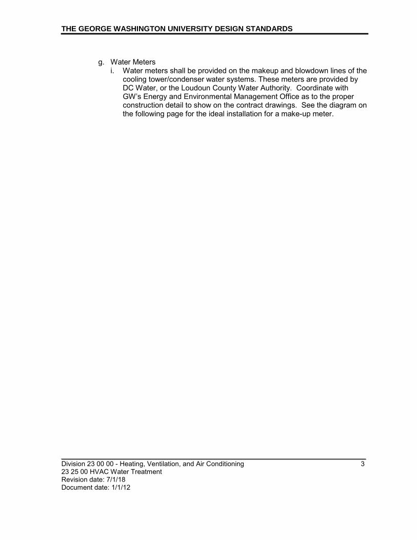
THE GEORGE WASHINGTON UNIVERSITY DESIGN STANDARDS
_________________________________________________________________________ Division 23 00 00 - Heating, Ventilation, and Air Conditioning 3 23 25 00 HVAC Water Treatment Revision date: 7/1/18 Document date: 1/1/12
g. Water Meters
i. Water meters shall be provided on the makeup and blowdown lines of the cooling tower/condenser water systems. These meters are provided by DC Water, or the Loudoun County Water Authority. Coordinate with GW’s Energy and Environmental Management Office as to the proper construction detail to show on the contract drawings. See the diagram on the following page for the ideal installation for a make-up meter.

THE GEORGE WASHINGTON UNIVERSITY DESIGN STANDARDS
_______________________________________________________________________ Division 23 00 00 - Heating, Ventilation, and Air Conditioning 4 23 25 00 HVAC Water Treatment Revision date: 7/1/17 Document date: 1/1/12
Diagram for Cooling Tower Meter Installation Ideal Installation for a Make-Up Meter
Ideal Installation for a Blowdown Meter
Blowdown to drain; flow controlled by solenoid valve
Condensate from tower Bypass line
Flanges or couplings for GWU meter, if used
Flanges or couplings for DC Water meter
Straight run of 5 pipe diameters
Ball valves
Straight run of 2 pipe diameters
Cooling tower make-up
Domestic cold water
Bypass line
Flanges or couplings for GWU meter, if used
Flanges or couplings for DC Water meter
Straight run of 5 pipe diameters
Ball valves
Straight run of 2 pipe diameters

_________________________________________________________________________ Division 26 00 00 - Electrical 26 00 00 Electrical, General Requirements
1
Revision date: 4/1/20 Document date: 7/1/11
THE GEORGE WASHINGTON UNIVERSITY DESIGN STANDARDS This document provides design standards only, and is not intended for use, in whole or in part, as a specification. Consultants referencing this information must always meet all applicable state and local building codes as well as all barrier free design requirements. Consultants must also refer to the entire set of Design Standards for additional information. Refer questions and comments regarding the content and use of this document to the George Washington University Project Manager.
26 00 00 ELECTRICAL
A. SUMMARY
This section contains GW-specific, general requirements for electrical work. Refer to building type space standards and related specification guidelines for additional information.
B. CODES, ACTS, STANDARDS AND OTHER REGULATIONS
1. State and Local Codes, Regulations and Authorities:
a. District of Columbia Municipal Regulations, including but not limited to: i. DCMR Title 12, Construction Codes
a.) International Energy Conservation Code/2012 (as amended by the 2013 Energy Conservation Code Supplement 12 DCMR I) a) The International Energy Conservation Code provides alternative paths for compliance (IECC vs. ASHRAE 90.1, Prescriptive vs Performance). GW prefers the IECC Prescriptive path of compliance because it does not require automatic shutdown of power receptacles.
C. GW STANDARDS
1. General:
a. Refer to the following specification guidelines for additional requirements: 26 09 23 Lighting Control Devices and 26 50 00 Lighting.
b. Metering: i. GW’s policy is that each campus building have no more than one utility
company account. If a building needs more than one utility company meter, the various meters shall be billed through a single account.
ii. GW’s policy is that all on-campus, independently-operated venues (e.g. Starbucks’) are submetered for all utilities.
iii. GW prefers that new venue meters be from the same manufacturers as existing venue meters. Existing venue meters include stand-alone E-Mon D-Mon electric meters or meters integral to the building’s switchgear section that serves a venue. Most of these meters include kW readouts in addition to kWh readouts.
iv. It is the intent of the Owner to have the primary utility meters for large buildings, and leased space tenant submeters, electronically metered and to have the metering data imported into the BAS and EMS. BAS/EMS

THE GEORGE WASHINGTON UNIVERSITY DESIGN STANDARDS
_________________________________________________________________________ Division 26 00 00 - Electrical 2 26 00 00 Electrical, General Requirements Revision date: 4/1/20 Document date: 7/1/11
should monitor kW demand, and accumulated kWh consumption, at the main building electric service – and at any submeters installed within the building, such as for leased space tenants.
c. The Electrical Contractor (hereafter referred to as Contractor) shall be licensed to do work in the District of Columbia (or if the work is on the Virginia Campus, licensed in the state of Virginia). i. The Contractor shall obtain all electrical permits and is responsible for
scheduling all DCRA (or in Virginia, Loudoun County) inspections and re-inspections as required.
ii. The Contractor shall ensure that electrical apprentices are properly supervised on site by no less than a DC-Licensed Journeyman Electrician (on our Foggy Bottom and Mount Vernon campus) or VA-Licensed Journeyman Electrician (VA Science and Technology Campus) at all times.
iii. The Contractor shall be responsible for the testing of all electrical work for compliance with the Contract Documents including NETA testing, vibration of rotating equipment, and for noise emission of all noise-producing electrical equipment.
iv. The Contractor shall conform all work, equipment and materials furnished with the existing GW Contract including Specifications, the DCRA (or County Building Code) having jurisdiction, the serving utility company, and the latest edition of the following: a.) The National Electrical Code b.) The National Electrical Manufacturers Association (NEMA) c.) The Institute of Electrical and Electronic Engineers (IEEE) d.) The Insulated Power Cable Engineers Association (IPCEA) e.) The American Society of Testing Materials (ASTM) f.) The American National Standards Institute (ANSI) g.) The requirements of Occupational Safety and Hazards Act (OSHA) h.) The Acceptance Testing Specifications by the International Electrical
Testing Association (NETA) i.) All other applicable Federal, state and local laws, rules, regulations,
standards, and/or ordinances. d. For all new construction projects and renovation work involving substantial
electrical component that requires a permit, a Selective Coordination Study and Arc Flash Analysis shall be performed from the utility to branch circuit panels including: Motor Control Centers; stand alone high inrush current motors; VFD controlled motor circuits and Emergency Systems (NEC 700 and 701 normal and emergency supplies). In addition, all electrical panels shall have ANSI PPE warning labels installed in a visible location on the front panel. For all renovations that have as a “scope of work” the replacement or the installation of: additional switchgear; distribution panels; branch circuit panels; high inrush current motors; VFD controlled motors and new or replacement service entrance cables and feeders shall be reviewed for an additional Selective Coordination Study to be performed to meet the requirements of

THE GEORGE WASHINGTON UNIVERSITY DESIGN STANDARDS
_________________________________________________________________________ Division 26 00 00 - Electrical 3 26 00 00 Electrical, General Requirements Revision date: 4/1/20 Document date: 7/1/11
NEC 110.9 and 110.10. New or added Emergency Systems shall be selectively coordinated (see NEC 700 and 701). The study shall be prepared utilizing manufacturer’s recommendations and the latest edition of NETA, ATS, NFPA 70B, NEC 70 and 70E, ANSI C2 “National Electrical Safety Code”, and ANSI/IEEE Guidelines. The study shall be prepared by a Professional Engineer employed by a qualified engineering firm that has a minimum of 5 years experience with coordination studies. Use SDK or equivalent computer software that is currently available for sale in the United States and has been upgraded with the latest revisions. No hand calculations are permitted.
e. All equipment shall meet the Coordination Study criteria. f. Utilize NETA-certified testing companies and NETA-certified testing
technicians. g. Field acceptance testing shall be performed by the Electrical Contractor per
NETA Acceptance Testing Specification including providing all paperwork certifying compliance with test parameters before energizing equipment.
h. Service Capacity i. Academic and Residence Hall Buildings: Electrical systems shall be
designed to accommodate future loads. Confirm exact parameters during programming phase.
i. Aluminum shall not be used in electrical systems. j. A Power Riser Diagram shall be included in each set of drawings. The
diagram shall show the entire electrical distribution from the electrical utility throughout the building. Each set of feeder cables shall be identified for type (ex: copper THHN 90), size (ex: 350 kcmil) and quantity (include neutral and grounding conductor). Each panel board on the diagram shall be identified by its alpha-numeric designator and ampere capacity.
2. Electrical Equipment Location a. Main electrical rooms shall have year round ventilation by relief or outside air. b. Small electrical rooms and closets shall be ventilated by exhaust and building
air. c. Transformers:
i. For Academic Buildings, there shall be no motors or other types of equipment located on the side of the transformer that feeds classroom or lecture hall circuits to avoid creating visible and audible disturbances in the presentation.
d. For special requirements related to classroom spaces, refer to Academic Technologies standards ‘The George Washington University AV Design Guidelines Document”.
3. Phasing Conductors a. 120/208 Volt: from left to right on the panelboard - black, red, blue. b. 277/480 Volt: from left to right on the panelboard - yellow, brown, orange

THE GEORGE WASHINGTON UNIVERSITY DESIGN STANDARDS
_________________________________________________________________________ Division 26 00 00 - Electrical 4 26 00 00 Electrical, General Requirements Revision date: 4/1/20 Document date: 7/1/11
4. Transmission and Distribution a. Wiring and Cable
i. All grounding electrode conductors, when entering the main electric room, shall conform to NFPA 70 250.52 and be exothermically welded to main grounding bus in all grounding electrode systems.
ii. All current carrying conductors and grounds shall be insulated copper. Wire type, size, covering, temperature rating, solid or stranded, connections and etc shall be suitable for the device, service and location as stated in the NEC.
iii. All distribution wiring from source to load shall be NETA-tested and meet acceptance by a NETA-certified technician prior to Substantial Completion of the project.
iv. All grounding shall be installed and accepted before energizing any power circuit.
b. MC cable must be thin steel type and contain insulated copper color-coded conductors. The green insulated grounding wire shall be the same gauge wire size as the current carrying conductors
c. Aluminum MC cable is not acceptable. d. MC cable is acceptable in concealed locations. MC cable must be supported
as required by the NEC before entering a connection box through an approved connector/grommet.
e. Home runs to a panel board are not permitted in MC cable. Run conduit from the panel board to a Junction box central to the loads being served. Run MC from the Junction box to the loads. Fixture wiring (for example) using MC Cable may require a few junction boxes with MC cable runs in between to complete a circuit however, the last junction box before the panel board must be connected with conduit.
f. MC Cable does not have a set length restriction if voltage drop requirements have been met but, will be naturally limited in length as junction boxes are placed in the areas central to the loads.
g. Threaded Rigid Metallic Conduit (RMC) and threaded RMC fittings shall be utilized outdoors and in hazardous locations. Use weather rated junction boxes to connect indoor EMT conduit with outdoor RMC.
h. All raceway connections to vibrating equipment shall be made with Liquidtight Flexible Metal Conduit (LFMC Steel wound) using listed fittings. The maximum length for LFMC connected to vibrating equipment is 6 feet. An equipment grounding conductor (sized per the NEC section 250.122) must be included with the current carrying conductors. Observe conduit fill requirements for LFMC and other requirements as required per NEC section 350.
i. Residence Halls: i. All bedroom outlet circuits shall be Arc-fault rated. ii. Residential units with more than 6 circuits shall have an individual load
center within the unit. a.) Load centers shall be factory-painted, color to be selected by
Architect.

THE GEORGE WASHINGTON UNIVERSITY DESIGN STANDARDS
_________________________________________________________________________ Division 26 00 00 - Electrical 5 26 00 00 Electrical, General Requirements Revision date: 4/1/20 Document date: 7/1/11
5. Switchboards and Panels a. Approved panel board manufacturers are the following:
i. Square D, ii. Siemens, and iii. GE.
b. New Construction: i. Panels in Academic Buildings generally shall have 25 percent spare
capacity consisting of spare breakers and/or spare spaces. All spare spaces shall be provided with all hardware installed from manufacturer.
ii. Panels in Residence Halls generally shall have 10 percent spare capacity consisting of spare breakers and/or spare spaces. All spare spaces shall be provided with all hardware installed from manufacturer.
c. Busbars shall be copper. d. Panelboards, disconnect switches, cabinets, etc shall not be located in public
spaces. If project condition makes installation in public spaces necessary, approval from Owner is required. In these cases, the distribution panel shall be lockable. Latches, not locks, shall be provided for panelboards located in electrical closets.
e. For Academic Buildings, each floor shall have at least one lockable electrical closet. Refer to Academic Building type standards for requirements.
f. Electronic or magnetically controlled breakers, rather than fused disconnects, shall be provided in main switchgear.
g. Panelboards shall be flush-mounted panels and have full height access to the ceiling for future raceways. Panelboards greater that 36 inches high shall have a hinged front cover: i. Hinged Front Cover: Entire front trim hinged to box and with standard
door within hinged trim cover. h. Future spaces for all switchgear shall be fully bussed, complete with all
necessary mounting hardware (without future circuit breaker) and located as shown on the panel schedule.
6. Branch Circuits a. Circuit breakers shall be bolted type. b. Each Telecom Closet shall be provided with one dedicated emergency power
branch circuit. 7. Receptacles, Telephone, and Data
a. Refer to building type space standards, Power and Data section for specific requirements.
b. Exterior Locations and Machine Rooms: i. Duplex and quad outlets in areas exposed to weather and water shall be
mounted in NEMA 3R enclosures with gasketed, weatherproof, and pluggable covers, per Code, and with a lockable option. Corrosion-resistant metal covers shall be provided.
c. Electrical outlets shall have a visible label on the cover plate indicating panel number and circuit number.

THE GEORGE WASHINGTON UNIVERSITY DESIGN STANDARDS
_________________________________________________________________________ Division 26 00 00 - Electrical 6 26 00 00 Electrical, General Requirements Revision date: 4/1/20 Document date: 7/1/11
d. Floor box cover plates shall be constructed of a material suitable to withstand the foot traffic/use of a space. Metal shall be used for high traffic areas. The door shall be permanently attached to the assembly.
8. Grounding and Bonding NEC 250 a. Install grounds and bonds to electrical equipment, switchgear, panelboards
and etcetera per the Code requirements of NEC 250. 9. Grounding Electrode System (NEC 250.50, 250.52, 250 53 and others as
required. a. The grounding electrode system shall be connected to a copper bus bar that
is located in the main electrical room. b. Bonding of the grounding electrode system shall be made to copper bus
bar(s) specifically manufactured for the purpose of connecting multiple ground conductors together from ground electrodes, water piping, structural steel, UFER ground, and etc. The method of connection to the ground bus bar is exothermic using a mold made for the purpose of joining bare copper conductor to copper bus bar.
10. Emergency Power Systems, Generators: a. During the schematic design and/or design development phase of a project,
the consultant shall provide documentation of all assumed loads, for GW review and approval, to ensure the generator is correctly sized.
b. For generator exhaust ductwork to be installed within a rated shaft in building interiors, ductwork shall be configured and routed to discharge gases vertically, eliminating horizontal transitions that would impede the vertical exhaust flow of the emitted gases/fumes to the exterior of the building.
c. Generator exhaust system installation shall be gas-tight to prevent exhaust gas fumes from entering/re-entering any inhabited room or building. Exhaust stack shall be terminated and located such that emissions on sensitve receptors, including people, windows, and fresh air intakes, are minimized.
d. Minimum stack height requirements: i. Generators with a power output ≥300 kW: Minimum stack height of 10 feet
above the facility rooftop or emergency engine enclosure, whichever is lower.
ii. Generators with a power output of ≥1 MW: Minimum stack height of 1.5 times the height of the building on which the stack is located. If proposed stack is lower than 1.5 times the building height or lower than the height of a building within the stack's area of influence, air dispersion modeling and analysis will be required to confirm additional emissions control technologies will not be required.
e. Sound-attenuated, weather-protective enclosures shall be provided for generators installed outdoors. Enclosures shall have a rating of 78 dBA (maximum rating) when the generator is located within 23' of a structure. Enclosures for generators located in close proximity to a building shall provide more robust sound attenuation than depending upon the generator KW.

THE GEORGE WASHINGTON UNIVERSITY DESIGN STANDARDS
_________________________________________________________________________ Division 26 00 00 - Electrical 7 26 00 00 Electrical, General Requirements Revision date: 4/1/20 Document date: 7/1/11
i. Enclosure appearance shall be approved by GW to ensure overall aesthetics are acceptable and in compliance with the campus plan.
f. For projects that require multiple generators, each unit shall be programmed to alternate as the lead generator to be initiated after loss of normal power, to ensure equal runtime.
g. Only factory and standard installation warranties shall be included. Extended warranties, first year maintenance visits, and/or additional maintenance services shall not be included due to the already established maintenance contract.
h. Approved manufacturers, no exceptions: i. Cummins ii. MTU Detroit Deisel iii. Kohler
11. Emergency Power Systems a. Residence Halls:
i. Back-up or standby generators shall have fuel storage sufficient for a run time of 24 hours at 75% of the maximum generator load. The number of gallons of fuel stored for the facility generator use would thereby include a run time of 2 hours or longer at 100% for life safety and the remainder at varying generator load.
12. Uninterruptible Power Supply (UPS) a. A central UPS system for GW DIT/GWorld/Security equipment shall be
provided for all buildings. b. Approved Equipment Vendor, no exceptions: APC by Schneider Electric c. See also GW DIT standards “GW DIT Equipment Rooms, Construction
Standards”, published by Communications Engineering Services, for requirements.
C. QUALITY CONTROL 1. For new construction projects, GW Electrical Inspector shall be notified, at least 2
days in advance, of the time when the following inspections will be performed by the authority having jurisdiction (AHJ): a. Temporary Power b. Ceiling Concealment or Close-in c. Wall Concealment or Close-in
D. PROJECT CLOSEOUT PROCEDURES 1. Procedures Prior to Substantial Completion
a. Final Inspection: GW Electrical Inspector shall be provided with documentation of final approval by the authority having jurisdiction (AHJ) for electrical, elevator, and fire alarm before substantial completion and partial occupancy.

THE GEORGE WASHINGTON UNIVERSITY DESIGN STANDARDS
_________________________________________________________________________ Division 26 00 00 - Electrical 8 26 00 00 Electrical, General Requirements Revision date: 4/1/20 Document date: 7/1/11
END OF SECTION

_________________________________________________________________________
_________________________________________________________________________ Division 26 00 00 – Electrical 1 26 09 23 Lighting Control Devices Revision date: 1/1/19 Document date: 9/22/09
THE GEORGE WASHINGTON UNIVERSITY DESIGN STANDARDS This document provides design standards only, and is not intended for use, in whole or in part, as a specification. Consultants referencing this information must always meet all applicable state and local building codes as well as all barrier free design requirements. Consultants must also refer to the entire set of Design Standards for additional information. Refer questions and comments regarding the content and use of this document to the George Washington University Project Manager.
26 09 23 LIGHTING CONTROL DEVICES
A. SUMMARY
This section contains design standards for lighting control systems. Refer to space standards for additional information.
B. GENERAL
Energy efficiency is among the highest priorities at the University. Consultants shall always strive to achieve the highest energy efficiency possible within the parameters of campus security, project budget and function. Selection of occupancy sensors, photo cells, and other lighting controls shall reflect this priority. Where manual override is provided, a device that returns to its automated settings after a pre-determined time period of space vacancy is preferred.
C. EXTERIOR LIGHTING CONTROL 1. Photocell Strategy:
a. The urban setting of GW buildings share "lit" public sidewalks that are illuminated at dusk by street lamps. Where public sidewalks or other public passages surrounding the building are not "lit", building light fixtures are to be provided. Foyer lighting may be reduced at night but illuminated enough to provide a "safe" place to be seen or make a call. The building photocell shall turn off lighting during the day except in times of inclement weather (turns on due to darkness) and a building timer shall be set to conserve energy by turning off specific fixtures where there is a duplicate public source of lighting and shall turn off redundant fixtures at entrances.
2. The University prefers Intermatic K4200 Stem and Swivel Mounting series photo cells for exterior lighting control, for its durability.
3. The photocell mounting location should be conducive to maintenance access.
D. INTERIOR LIGHTING CONTROLS
1. Time Switch a. Timers shall generally be provided in large mechanical spaces and storage
spaces with large obstructions. Emergency lighting that allows for safe exiting shall always be provided in the event that general lighting switches off with an occupant inside.
THE GEORGE WASHINGTON UNIVERSITY DESIGN STANDARDS
_________________________________________________________________________ Division 26 00 00 – Electrical 2 26 09 23 Lighting Control Devices Revision date: 1/1/19 Document date: 9/22/09
b. Timer shall have settings for flashing the room lights and making an audible noise well before lights time out to give occupants a chance to reset the timer or safely exit the space.
c. Typical timer model, or approved equal by Hubbell, Intermatic, or Sensor Switch: i. Watt Stopper TS-400
2. Interior Occupancy Sensors
a. Manufacturers and technologies to use at the University i. Three basic occupancy sensing technologies:
a.) Passive infrared (PIR): senses motion by tracking body heat b.) Ultrasonic (US): responds to changes in sound waves emitted and
returned to the sensor device, due to motion or vibration c.) Microphonics (MP; trademarked microphonic technology by Sensor
Switch only): responds directly and solely to perceived sound ii. Technology combinations currently available by the following three
approved manufacturers for commercial grade wall- and ceiling-mounted occupancy sensors: a.) Watt Stopper: PIR only; US only; dual technology (PIR and US) b.) Hubbell: PIR only; US only; dual technology (PIR and US) c.) Sensor Switch: PIR only; dual technology (PIR and MP)
b. Sensors shall provide an adjustment range of approximately five to twenty minutes, energizing lights for the set time period after sensing the presence of an occupant. Except for public restrooms and reception areas, ‘manual on’ operation (i.e. vacancy sensors) is generally recommended.
c. Automatic Shutoff: i. Space Control for lighting in spaces that include classrooms, lecture halls,
conference rooms, break rooms, storage and supply rooms, restrooms and office space: a.) The default (installed) setting shall be automatic shutoff within 20
minutes of vacancy per ASHRAE 90.1 requirements. d. Select and locate sensors to avoid false triggers. Except in cases where
HVAC operations would interfere with sensor operation and small housekeeping spaces, sounds must activate sensors.
e. Coverage Area: i. Wall Mounts: permissible up to 1200 sq ft (approximately 40’ out) and
device limitations ii. Ceiling Mounts (8 to 15 ft high): permissible to cover up to 2,000 sq. ft.
(approximately 45’x45’) in accordance with device limitations. Provide two or greater ceiling mount occupancy sensors for rooms exceeding the abovementioned area.
f. Verify motion sensor switch locations for support spaces such as housekeeping closets, electrical rooms, etc.
g. New Construction: Occupancy sensors shall be low voltage and allow the option for integration with building automation and energy management systems. Existing buildings on campus have both line and low-voltage occupancy sensors. For retrofit projects, select format that best accommodates existing conditions including voltage, amperage, and room size.

THE GEORGE WASHINGTON UNIVERSITY DESIGN STANDARDS
_________________________________________________________________________ Division 26 00 00 – Electrical 3 26 09 23 Lighting Control Devices Revision date: 1/1/19 Document date: 9/22/09
h. The chart below outlines general University occupancy sensor guidelines for new construction. Similar strategies are appropriate for renovations, but are dependent on current wiring design. The designer must coordinate this information with the balance of the standards, including standard lamps and space-specific lighting requirements. Note that wherever a wall-mount sensor is noted, it may instead be a ceiling-mount sensor if appropriate and cost effective. However, the reverse is not true. Ceiling mounts are more tamper-proof than wall-mounts and are necessary in many spaces. Also note that the Suggested Solutions noted below are a minimum threshold. Therefore, if a single technology is noted, but dual technology is warranted and approved in a specific space, it will be acceptable.
Space Function Notes (“Small space is generally defined as less than 200 square feet”)
Suggested Solution
US=Ultrasonic
PIR=Passive Infrared
MP=Microphonics
DT=Dual Technology
Breakout Room / Conference Room / Seminar Room / Study Room
Small space DT
Wall-mount with manual on/off switch
Large space DT
Ceiling-mount with manual on/auto off switch
Classroom, excluding Physics Labs
Multiple uses, such as chalk or white board, projector use, note-taking, class presentations
DT (provide with light level sensor and/or photo cell in spaces with abundant natural light)
Ceiling-mount with manual on/auto off switch
Computer Lab DT (PIR and US, provide with light level sensor and/or photo cell in spaces with abundant natural light)

THE GEORGE WASHINGTON UNIVERSITY DESIGN STANDARDS
_________________________________________________________________________ Division 26 00 00 – Electrical 4 26 09 23 Lighting Control Devices Revision date: 1/1/19 Document date: 9/22/09
Ceiling-mount with manual on/auto off switch
Dining Spaces, Public DT
Ceiling-mount
Electrical Room / Mechanical Room
Large space, where occupant may be out of view from various points in the space, due to obstructions
Timed switch with both audible and visual warning before timing out.
Small, generally unobstructed space
Wall-mount timed switch with visual warning before timing out.
Telecom Room/ Security Room
Small, generally unobstructed space
PIR
Wall-mount
Gymnasium or Fitness Center
Constant movement in space
DT (provide with light level sensor and/or photo cell in spaces with abundant natural light)
Ceiling-mount
Hallways and Corridors, Residential and Academic1
Occupants passing through, creating constant movement
DT
Ceiling-mount
Health Care Exam Rooms
DT
Wall-mount
Housekeeping closet Small, unobstructed space
PIR
Wall-mount
Laundry Room, shared Large open room with frequent noises, even when unoccupied
US or DT (PIR and US)
Ceiling-mount
Library Reading Areas DT (PIR and US)
Ceiling-mount

THE GEORGE WASHINGTON UNIVERSITY DESIGN STANDARDS
_________________________________________________________________________ Division 26 00 00 – Electrical 5 26 09 23 Lighting Control Devices Revision date: 1/1/19 Document date: 9/22/09
Library Stacks DT (PIR and US)
Ceiling mount
Lobby PIR – where installed, but installation is space-dependent
Ceiling mount
Mail Room Enclosed space DT
Wall-mount
Open or undefined space
Space-dependent
Ceiling-mount
Media-Rich Space Space where media noise from television, radio or similar is played, whether occupied or not
DT (PIR and US)
Ceiling mount
Office, Open Partitioned work stations
DT (PIR and US)
Ceiling-mount
Office, Private Available natural or borrowed light
DT with light level sensor and/or photocell and manual on/auto off switch (“vacancy sensor”)
Wall-mount
No alternate light source available
DT
Wall-mount
Pantry Shared kitchen area PIR
Wall-mount
Residence Hall Apartments
Kitchen DT

THE GEORGE WASHINGTON UNIVERSITY DESIGN STANDARDS
_________________________________________________________________________ Division 26 00 00 – Electrical 6 26 09 23 Lighting Control Devices Revision date: 1/1/19 Document date: 9/22/09
Wall-mount
Reception Areas DT
Ceiling-mount
Restroom, Public / Locker Room
Single occupant DT
Wall-mount
Multiple occupants, partitioned
DT
Ceiling-mount
Stairwells Low usage typically
“Dimming sensors” which provide minimal (1 f-c+) light until occupancy is detected, increasing output to 100% for 10 minutes.
Storage Large space, where occupant may be out of view from various points in the space, due to obstructions
US
Ceiling -mount
Small, generally unobstructed space
PIR
Wall-mount
Work Room
Open area; Shared copy, files, and similar work space
PIR
Wall-mount
Partitioned space DT
Wall-mount
Note:
1. Occupancy sensors shall not be provided in hallways and corridors of residence halls. 2. Dimming sensors shall be provided in residence hall stairwells.
3. Ballast Type

THE GEORGE WASHINGTON UNIVERSITY DESIGN STANDARDS
_________________________________________________________________________ Division 26 00 00 – Electrical 7 26 09 23 Lighting Control Devices Revision date: 1/1/19 Document date: 9/22/09
Program-start type ballasts shall be used for lighting controlled via occupancy sensor.
4. Photocells
Daylighting controls for naturally side-lighted spaces shall be provided as required by Code and ASHRAE 90.1. Photocells may be incorporated into the occupancy sensor, or provided as a separate item. Occupancy sensors with integral photocell shall allow for adjustability and the option for override. Timer controls have historically been unsuccessful at the University due to afterhours housekeeping staff schedules.
5. Space-Specific Lighting Controls
a. Approved Manufacturer – Dimming, Switching and Control Systems: i. Basis of Design: Lutron Electronics Co., Inc.
a.) The preferred styles and those most commonly used at GW are the following: Nova T, Maestro, and Ariadni.
b. Classrooms, Conference Rooms, and Seminar Rooms (capacity greater than 10): i. Provide ceiling-mounted, dual technology occupancy sensors. ii. Provide means to control the projection screen area at the front of the
room independently from general room lighting. Front row of light shall also illuminate the projection screen area.
iii. Lighting control requirements are dependent upon category of classroom and program for the space. Criteria including room size, room shape, floor layout, project budget, and anticipated use of the room by faculty and students shall be considered. The type of media technology to be used in the classroom shall be taken into consideration. Dimming or switching shall reduce lighting levels to achieve the greatest energy efficiency possible after program requirements have been satisfied. Refer to Classroom Design Specifications by GW Academic Technologies for additional information.
iv. For large rooms with abundant natural light, “scene” control (i.e. variable output on a row or fixture basis, e.g. Lutron GRAFIK EYE multi-scene dimming control) shall be investigated for cost, savings, and payback as an alternative
c. Private Offices i. Provide fixtures and controls that accommodate reduced light level as
desired or when additional light source is available. Occupancy sensors with manual override shall always be provided.
d. Large public or semi-public rooms such as Lounges, Reception Areas, and Libraries i. Lighting control requirements are dependent upon criteria including room
size, room shape, floor layout, project budget, and anticipated use of the room. Dimming or switching shall reduce lighting levels to achieve the greatest energy efficiency possible after program requirements have been satisfied.
ii. Lights shall be controlled by either wall or key switches: a.) Wall switches must be mounted in locations not readily accessible to
the general public.

THE GEORGE WASHINGTON UNIVERSITY DESIGN STANDARDS
_________________________________________________________________________ Division 26 00 00 – Electrical 8 26 09 23 Lighting Control Devices Revision date: 1/1/19 Document date: 9/22/09
b.) Key switches must be mounted in readily accessible locations. c.) Provide 2-prong key switches in Residence Halls.
iii. The default (installed) sensor activation time shall be 30 minutes for these spaces.
END OF SECTION

_________________________________________________________________________
_________________________________________________________________________ Division 26 00 00 – Electrical 1 26 29 23 Variable-Frequency Motor Controllers Revision date: 1/1/14
Document date: 7/1/13
THE GEORGE WASHINGTON UNIVERSITY DESIGN STANDARDS This document provides design standards only, and is not intended for use, in whole or in part, as a specification. Consultants referencing this information must always meet all applicable state and local building codes as well as all barrier free design requirements. Consultants must also refer to the entire set of Design Standards for additional information. Refer questions and comments regarding the content and use of this document to the George Washington University Project Manager.
26 29 23 VARIABLE-FREQUENCY MOTOR CONTROLLERS
A. SUMMARY
This section contains general standards for variable-frequency motor controllers.
B. PRODUCTS
1. Approved Manufacturers; no exceptions
a. Yaskawa b. ABB, Inc.
C. APPLICATION
1. GW strongly prefers that variable frequency speed controllers be located indoors,
where they are protected from sunlight, extreme temperatures and moisture. If the controlled equipment is located outdoors, then the designers must account for the distance between the controller and the controlled motor, and make provisions to ensure reliable and safe operation, such as providing a disconnect switch at the motor, and specifying an appropriate size, insulation and raceway for the conductors.
END OF SECTION

_________________________________________________________________________
_________________________________________________________________________ Division 26 00 00 – Electrical 1 26 50 00 Lighting Revision date: 4/1/19 Document date: 9/22/09
THE GEORGE WASHINGTON UNIVERSITY DESIGN STANDARDS This document provides design standards only, and is not intended for use, in whole or in part, as a specification. Consultants referencing this information must always meet all applicable state and local building codes as well as all barrier free design requirements. Consultants must also refer to the entire set of Design Standards for additional information. Refer questions and comments regarding the content and use of this document to the George Washington University Project Manager.
26 50 00 LIGHTING
A. SUMMARY
This section contains design standards for lamps and fixtures. Refer to building type space standards and related specification guidelines for additional information.
B. GENERAL
1. Energy efficiency is among the highest priorities at the University. Consultants
shall always strive to achieve the highest energy efficiency possible within the parameters of campus security, project budget and function.
2. Special consideration to maintenance access shall always be given. This includes ensuring fixtures can be reached via practical measures for routine lamp and ballast replacement.
3. In order to facilitate servicing, recessed “can” compact fluorescent light fixtures shall be of a design where the ballast is not remote from the lamp. Maintenance staff has undue difficulty replacing ballasts when they are remote.
4. For interior application, ceiling-mounted light fixtures are generally preferred, but wall-mounted are acceptable as appropriate to the design.
5. Light levels shall comply with Illuminating Engineering Society of North America (IESNA) current recommendations. Examples of current IESNA lighting levels include: a) offices, classrooms, and laboratories: 30-50 foot-candles (depending on specific work tasks) on desks and table tops; b) hallways: 5-8 foot-candles; c) stairwells: 5-8 foot candles; d) restrooms: 5-8 foot-candles. An expanded list of requirements per space type is provided in the chart below. For additional spaces, refer to the most current issue of the IESNA Lighting Handbook.
6. Lighting power densities shall be reduced below ASHRAE/IES 90.1 2010 (most current version in effect at the time of writing) and LEED to meet energy conservation goals.
Space Type Illuminance (IESNA)
ASHRAE 90.1 2010 (Space-by-Space
Method) Lighting Power
Density (watts/ft2)4 Corridor/Transition 10-15 fc 0.5
Lobby 10-20 fc 0.9 Lounge/Recreation 15-20 fc 0.73

THE GEORGE WASHINGTON UNIVERSITY DESIGN STANDARDS
_________________________________________________________________________ Division 26 00 00 – Electrical 2 26 50 00 Lighting Revision date: 4/1/19 Document date: 9/22/09
Space Type Illuminance (IESNA)
ASHRAE 90.1 2010 (Space-by-Space
Method) Maximum Lighting Power Density Allowed
(watts/ft2)5
Conference/Meeting/Multipurpose 30-40 fc 1.23 Copy/Fax/File/Mail/Coffee 30-50 fc Lab Support/Prep 45-55 fc
Laboratories – Ambient1 30-40 fc 1.28 Laboratories – Task2 40-50 fc Medical Exam Office 50 fc 1.66 Mechanical/Electrical 30-50 fc 0.95 Art Studio 50 fc Auditorium 30-50 fc 0.79 Telecommunications Closet3 50 fc Microscope Rooms 40-50 fc Offices – Enclosed 30-50 fc 1.11 Offices – Open Plan 40-50 fc 0.98 Active Storage/Equipment 15-20 fc Inactive Storage 5 fc 0.3 Locker Room 10 fc 0.75 Restrooms 5 – 8 fc 0.98 Classroom/Teaching Labs & Large Seminar
40-50 fc 1.24
Library - Stacks 30 fc 1.71 Library - Reading Area 50 fc 0.93 Museum – General Exhibition 5-50 fc4 1.05 Museum Collection Storage 30 fc Dining Area 10-20 fc 0.65 Food Preparation 50 fc 0.99 Parking Garage - Garage Area 0.19 Stairwell per Code Corridor per Code Notes:
1. Brightness: LED luminaires, in a space with an 8’ ceiling, shall deliver a minimum of 2000 lumens of light.
2. Ambient horizontal Illuminance levels in labs and lab support spaces, shall be measured at a work surface height of 36”.
3. Task lighting shall be designed to boost light levels to 70-80 fc on benches and work surfaces.
4. Refer also to GW DIT Equipment Room Construction Standards. 5. Amount of light level (and light exposure to the objects) depends upon sensitivity
of the object and how guests will view it (Very Sensitive 5-10 fc, Sensitive 15-20 fc, Less Sensitive 30-50 fc).
6. Numbers reflect the lighting power density allowed per version of ASHRAE 90.1 in effect at the time of revision of this document.

THE GEORGE WASHINGTON UNIVERSITY DESIGN STANDARDS
_________________________________________________________________________ Division 26 00 00 – Electrical 3 26 50 00 Lighting Revision date: 4/1/19 Document date: 9/22/09
7. For ease of maintenance and lamp storage requirements, the lighting design
shall utilize a minimum number of different lamp and fixture types to meet space and program requirements.
8. Program-start type ballasts shall be utilized. 9. Installation:
All lighting fixtures shall be securely fastened to the building structure independent of the suspended ceiling.
C. INTERIOR LAMPS
1. Interior lamps shall have the following color temperature:
a. 4000K LED – Academic and Administrative Spaces b. 3000K LED - Residence Halls c. Mechanical and electrical rooms in all building types shall have 4000K LED
lighting.
2. LEDs a. In order to maximize energy conservation and for life cycle benefits, LED
lighting shall be specified. b. Designer shall specify only reputable manufacturers with a minimum of 20
years in the industry who provide a 5-year warranty on both the LED lighting module and the power supply.
c. Designer shall specify LED fixtures that allow lamp module replacement rather than replacement of the entire fixture, for ease of maintenance.
d. LED driver to be located within luminaire or within plug. e. At least three replacement fixtures or 1% of the total number of each type of
LED fixture shall be provided for attic stock.
D. INTERIOR LIGHT FIXTURES
1. Multi-Occupant Restrooms
a. The light fixture nearest the main restroom door shall be on a 90 minute battery back-up but not on the emergency circuit.
2. Light Fixtures, Residence Halls: a. General (Bedroom/Kitchen/Entryway) – Low Profile, Flush Mount, 14” Round
i. Approved Product; No Exceptions: a.) Manufacturer: Lithonia b.) Model:
a) FMLRL 14 (Standard) b) FMLRDL 14 (Alternate)
c.) Lamp Type: LED d.) Finish/Material: White acrylic diffuser e.) Color Temperature: 3000K
b. Bathroom Ceiling – LED Flush Mount, 7” Round, i. Approved Product; No Exceptions:
a.) Manufacturer: Lithonia

THE GEORGE WASHINGTON UNIVERSITY DESIGN STANDARDS
_________________________________________________________________________ Division 26 00 00 – Electrical 4 26 50 00 Lighting Revision date: 4/1/19 Document date: 9/22/09
b.) Model: Versi Lite a) Dry Application: FMML b) Shower Application: FMML WL
c.) Finish/Material: Textured white acrylic diffuser d.) Lamp Type: LED e.) Color Temperature: 3000K
c. Lavatory Area/Vanity – Linear Flush Mount, 2’ LED Wrap i. Approved Product; No Exceptions:
a.) Manufacturer: Lithonia b.) Model: FMLWL24 c.) Lamp: LED d.) Finish/Material: White acrylic diffuser e.) Color Temperature: 3000K
d. Surface Mount, 1’X4’: i. Approved Products and Manufacturers:
a.) Pinnacle Lucen LU14 b.) Lithonia ALLS4 c.) Lamp: LED d.) Finish/Material: White e.) Color Temperature: 3000K
e. Suspended Fixture-Exposed Ceilings, 1’X4’: i. Approved Products and Manufacturers:
a.) Lithonia Grad Linear b.) Philips Linear TruGroove Suspended c.) Focal Point Seem d.) Lamp: LED e.) Finish/Material: White f.) Color Temperature: 3000K
f. Corridor Wall-Mounted Light Fixtures i. Fixture Description: Wall-recessed, lensed linear fixture, 2’ long X 1-1/2”
wide flanged trim X 3” deep, extruded aluminum housing, high impact-resistance, extra diffuse acrylic lensing, integral electronic driver, silver finish.
ii. Basis of Design Product: a.) Manufacturer/Line: Selux - M36LED b.) Model: #L36R1-1L35-NB-TBD-02-SV-120
a) Or equal by one of the following manufacturers: i) Zumbotel ii) Alight
c.) Lamp: LED d.) Finish: Continuous aluminum wall bracket, silver finish e.) Color Temperature: 3000K
g. Custom light fixtures shall not be provided for residence halls.
3. Light Fixtures, Academic and Administrative Spaces: a. Standard 2x2
i. Lithonia 2BLT ii. Philips FluxGrid iii. Focal Point Equation 2

THE GEORGE WASHINGTON UNIVERSITY DESIGN STANDARDS
_________________________________________________________________________ Division 26 00 00 – Electrical 5 26 50 00 Lighting Revision date: 4/1/19 Document date: 9/22/09
b. Standard 2x4 i. Lithonia 2BLT ii. Philips FluxGrid iii. Focal Point Equation 2
c. Standard 1x4 i. Lithonia 2BLT ii. Philips FluxGrid iii. Focal Point Equation 2
d. Standard Suspended i. Lithonia Grad Linear ii. Philips Linear TruGroove Suspended iii. Focal Point Seem
e. Standard Linear Recessed i. Philips TruGroove Recessed ii. Focal Point Seem iii. Pinnacle Edge
E. EXTERIOR LIGHT FIXTURES
1. Lamp Posts
a. BEGA - 77 120 b. BEGA - 77 180 c. BEGA - 88 260 d. BEGA - 84 403 e. BEGA - 77 928 f. Typical - Washington Family of Streetlight Poles
2. Lighting Bollards a. BEGA - 84 602 b. BEGA - 77 589 c. BEGA - 77 334 d. BEGA - 84 682 w/ 99 620 e. BEGA - 99 554 f. Sentry – SCI-W-BOL-LED
3. Wall Mount Architectural a. BEGA - 24 506 b. BEGA – 66 698 c. BEGA – 22 453 d. Philips – 101 LED Sconce e. Lithonia – WST LED f. Sea Gull – 89940-12
4. Wall Mount Service a. Lithonia – OLW14 b. Philips – Pure Form LED Wall Sconce c. BEGA - 24 816
5. Landscape Accent a. Cast Landscape b. Unique Lighting Systems c. Hinkley Lighting

THE GEORGE WASHINGTON UNIVERSITY DESIGN STANDARDS
_________________________________________________________________________ Division 26 00 00 – Electrical 6 26 50 00 Lighting Revision date: 4/1/19 Document date: 9/22/09
6. Exterior Stairs/Steplight (If Applicable) a. BEGA – 22 375 b. Philips – RSB2 c. Hinkley – 59040
7. Building Name a. BEGA – 444419 b. Hinkley – 15452 c. WAC – WS-W177
F. STANDARD EXTERIOR LIGHT SPECIFICATIONS
1. Outdoor Light Levels
a. Primary Walkways and Safety Areas - 2 foot-candles (FC) average and .5 FC minimum
b. Secondary Walkways and Other Misc Areas i.e. Bike Racks - 1 FC and .25 FC minimum
2. LED Color Temperature 4000K 3. Recommended Lumens
Mounting Height (Feet) Recommended Lumen Maximums 6 500 - 1000 lumens 8 600 - 1,600 lumens 10 1,000 - 2,000 lumens 12 1,600 - 2,400 lumens
G. EXTERIOR LIGHTING REFERENCES
1. https://www.ies.org/product/lighting-for-exterior-environments/ 2. http://www.darkskysociety.org/handouts/LightingPlanGuidelines.pdf 3. https://www.energy.gov/eere/buildings/articles/doe-publishes-gateway-report-
pedestrian-friendly-outdoor-lighting 4. https://www1.eere.energy.gov/buildings/publications/pdfs/ssl/2013_gateway_ped
estrian.pdf 5. https://neighborhood.gwu.edu/campus-planning
http://www.officearchitect.virginia.edu/pdfs/UVaExteriorLightingStudyFinal.pdf 6. https://facilities.princeton.edu/sites/facilities/files/2.9-15.pdf 7. https://www.bega-us.com/ 8. http://www.cast-lighting.com/ 9. https://www.uniquelighting.com/ 10. http://www.waclighting.com/products/307 11. http://www.hinkleylighting.com/ 12. http://www.lighting.philips.com/main/prof/outdoor-luminaires#pfpath=0-
OCOUTD_GR 13. http://www.lithonia.com/pt/outdoor/#.W5v4SuhKiUk 14. https://comp.ddot.dc.gov/Documents/Streetlight%20Policy%20and%20Design%2
0Guidelines.pdf

THE GEORGE WASHINGTON UNIVERSITY DESIGN STANDARDS
_________________________________________________________________________ Division 26 00 00 – Electrical 7 26 50 00 Lighting Revision date: 4/1/19 Document date: 9/22/09
H. PARKING GARAGE LIGHTING
1. Lighting Requirements: a. Light levels shall comply with recommended illumination standards of IESNA.
The following minimum maintained horizontal lighting levels shall be provided (measured at the floor): a) basic surfaces - 1 foot-candle; stairways - 2 foot-candles; ramps (day) - 2 foot-candles; ramps (night) -1 foot-candle; entrances (day) - 50 foot-candles; and entrances (night) - 1 foot-candle.
2. Products:
a. Provide LED fixtures as required to achieve target illumination level. Fixture efficacy (lumens per watt) shall be greater than 79.
b. Lighting/Energy Efficiency: Fixtures shall be equipped with an occupancy sensor to reduce light level and lighting load by 50-80% during periods without occupancy. Emergency egress illumination required by Code shall be maintained at all times.
c. Occupancy sensors shall be initially set for a delay of 10 minutes before reducing the light/load levels and shall be capable of a range from 5-30 minutes.
d. Consider alternative schemes to maximize energy savings and minimize fixtures through new technologies (e.g. Philips VizorLED Gen 2).
e. Lamps: i. LED ii. Length: 48” iii. Cool White (4000 K)
f. Design to withstand temperature of 32 degrees Fahrenheit or higher when garage is below grade. Lamps may be required to withstand lower temperatures for open, exposed, above-grade parking structures.
I. EXIT SIGNS 1. Listings: UL damp location listed 32° - 122°F standard, comply with UL 924;
NFPA 101 (current Life Safety Code), NEC; and OSHA for sign colors, visibility, luminance and lettering size, comply with local authority having jurisdiction
2. Internally Lighted Signs: a. Lamps for AC Operation: LED (typical LED life 10 years)
3. Exit signs for high abuse environments shall have proper mounting accessories to allow support of fixture per the manufacturers recommendations.
4. Exit sign shall have battery backup.
5. Approved Product and Manufacturer, or equal product by approved manufacturers: a. LED Edge-Lit (EDG, EDGR) Exit Sign by Lithonia Lighting
(http://www.acuitybrandslighting.com/library/ll/documents/specsheets/edg-edgr.pdf) i. Letter Color: Red
THE GEORGE WASHINGTON UNIVERSITY DESIGN STANDARDS
_________________________________________________________________________ Division 26 00 00 – Electrical 8 26 50 00 Lighting Revision date: 4/1/19 Document date: 9/22/09
ii. Acrylic panels – letters measure 6” high with ¾” stroke, with 100 ft. viewing distance rating, based on UL 924 a.) “EXIT” must not be seen as a reversed image from the back of the
sign. Designer shall specify either a mirrored separator panel for double faced signs or a mirrored backing panel for single face signs.
iii. Housing Construction: Extruded aluminum brushed finish iv. Mounting:
a.) EDG – Universal surface mounting (top, end, or back) b.) EDGR – Recessed mounting
v. Battery Type: Nickel Cadmium vi. Directional Indicators: Chevron Directional Knockouts vii. Dual voltage input capacity: 120/277 viii. Includes diagnostic testing for on-demand visual inspection ix. Warranty: 3-year limited x. Green Environmental Attribute: Low energy consumption
b. Alternate sign styles shall be submitted to Facilities Services for review and approval.
J. OUTDOOR LIGHTING
1. Outdoor lighting design shall be environmentally responsible and strive to meet
International Dark-Sky Association and LEED requirements while meeting security lighting requirements. a. Fixtures shall be low intensity, shielded, full cut-off fixtures to prevent light
spill over to adjacent properties and to prevent any illumination projection skyward. Minimize use of non-essential lighting for landscape and architectural purposes.
b. Fixtures shall be LED unless submitted to Facilities Services for review and approval.
2. Ballasts for site lighting shall be above ground or remote. Flush in-ground fixtures shall have a minimum of 3 feet of smooth stone (<3/4 inches) below the fixture for drainage.
K. WARRANTY 1. For ease of repair and maintenance, all parts of a light fixture shall be available
for the entire warranty period.
END OF SECTION

_________________________________________________________________________
_________________________________________________________________________ Division 27 00 00 - Communications 1 27 00 00 Information Technology Revision date: 4/1/20 Document date: 7/1/11
THE GEORGE WASHINGTON UNIVERSITY DESIGN STANDARDS This document provides design standards only, and is not intended for use, in whole or in part, as a specification. Consultants referencing this information must always meet all applicable state and local building codes as well as all barrier free design requirements. Consultants must also refer to the entire set of Design Standards for additional information. Refer questions and comments regarding the content and use of this document to the George Washington University Project Manager.
DIVISION 27 00 00 INFORMATION TECHNOLOGY
A. REFERENCE STANDARDS In addition to the GW Design Standards, consultants must be aware of GW Information Technology requirements that are specific to the University which further direct construction work. The consultant, with the guidance of GW, shall determine the applicability of these requirements that govern the work. 1. For internal GW FPCM access, GWIT standards are available in the
following location: https://gwu.box.com/s/74n4y3c4wcmiv2vwwajniblevr78r2bj.
2. Consultants shall contact their GW Development Manager/Project Manager to obtain the following reference standards:
a. GW Equipment Rooms Construction Standards (dated 2/22/2013) b. Building Standards for IT Services (dated 10/11/2013) c. Facilities Building Automation Reference Architecture (07/26/2016)
B. GENERAL
1. The project shall have a separate series of drawings that indicate requirements
for security, electronic access control and information technology: GW CFT Security and Access Standards, GWorld (08 74 00 Access Control Hardware), Information Technology (27 00 00), and Security (28 00 00 Electronic Safety and Security). The set of drawings shall show the following components, including but not limited to: all GWorld reader locations, camera locations, security door contacts, glass breaks, PIM locations, WAP locations, data, and voice. All of these will be installed by the Owner’s vendors. a. The discipline designator ‘X’ shall be used for this series of drawings. Refer to
GW Reference Standard ‘FIM Procedures Manual’ for additional information.
END OF SECTION

_________________________________________________________________________
_________________________________________________________________________ Division 27 00 00 – Communications 1 27 42 00 Electronic Digital Signage Systems.doc Revision date: 4/1/20 Document date: 7/1/10
THE GEORGE WASHINGTON UNIVERSITY DESIGN STANDARDS This document provides design standards only, and is not intended for use, in whole or in part, as a specification. Consultants referencing this information must always meet all applicable state and local building codes as well as all barrier free design requirements. Consultants must also refer to the entire set of Design Standards for additional information. Refer questions and comments regarding the content and use of this document to the George Washington University Project Manager.
27 42 00 ELECTRONIC DIGITAL SIGNAGE SYSTEMS
A. SUMMARY
This section contains general standards for digital signage displays. Consult with GW Academic Technologies for additional information.
B. REFERENCE STANDARDS
1. Technical Standards for Digital Signage, GW Division of Information Technology
C. GENERAL 1. Refer to GW Reference Standard, Technical Standards for Digital Signage, for
detailed requirements. 2. Content displays shall be LCD (plasma displays are prone to burn-in with static
content). 3. Displays are required to support a 720P (1366 X768) resolution. 4. Content Management uses a software application called CoolSign which
facilitates content manipulation, remote uploads, timing sequences, etc. 5. All digital signs must be connected to a PC (usually a small form factor) to run
the CoolSign software. A dedicated network drop and power outlet is required near a sign.
6. PCs are typically mounted behind the signs. Other implementations can be considered if there is conduit running from the sign to the PC location. It is preferred that the PC and sign locations are close to each other.
7. Mounting details shall be specific to the size of the display and implementation of where it is to be used.
8. Displays should be “pro” models and not “consumer” grade models. a. Acceptable Manufacturer and Product:
i. Samsung DX by Samsung
END OF SECTION

_________________________________________________________________________
_________________________________________________________________________ Division 27 00 00 – Communications 1 27 53 13 Clock Systems Document date: 7/1/13
THE GEORGE WASHINGTON UNIVERSITY DESIGN STANDARDS This document provides design standards only, and is not intended for use, in whole or in part, as a specification. Consultants referencing this information must always meet all applicable state and local building codes as well as all barrier free design requirements. Consultants must also refer to the entire set of Design Standards for additional information. Refer questions and comments regarding the content and use of this document to the George Washington University Project Manager.
27 53 13 CLOCK SYSTEMS
A. SUMMARY
This section contains general standards for secondary clocks compatible with a building-wide synchronized clock system currently installed at several facilities on campus. This section does not apply to new clock systems for new construction/major renovation projects for which there is no standard at this time.
B. GENERAL
1. Master and Secondary Clock System Description: Maintain accurate,
synchronized time and transmit time correction signals over dedicated system wiring from a master clock to secondary indicating clock.
C. STANDARDS 1. Master Clock System (Existing systems in the following buildings; for reference
only – Law School, Gelman Library, Lerner Health and Wellness Center): a. Description: Microprocessor-based, software-controlled unit complying with
Class A device requirements in 47 CFR 15. b. Basis of Design Product:
i. Simplex 6400 Series 2. Analog Secondary Clock:
a. Wired, synchronized analog clock connected to Simplex master clock systems for power and correction
b. Dimension: 12” diameter c. Mounting: surface-mounted (12” diameter clock includes security bracket) d. Features:
i. Microprocessor-controlled movement ii. Accuracy to within +/- 1 second of master clock iii. 15 minutes of backup power (without the use of batteries) iv. LED indicator for improved diagnostics v. Reduced power consumption vi. Impact-resistant black plastic case vii. Shatter-resistant clear, polycarbonate crystal viii. 5 year warranty ix. UL listed
e. Power Requirements: 120vac f. Basis of Design Product:
i. AllSync Plus 120vac 6310-9200 Series Molded Case System Clocks by American Time & Signal Company; no exceptions

THE GEORGE WASHINGTON UNIVERSITY DESIGN STANDARDS
_________________________________________________________________________ Division 27 00 00 – Communications 2 27 53 13 Clock Systems Document date: 7/1/13
a.) Model No. U54BAAA332-WEB b.) Dial Style 32
END OF SECTION

_________________________________________________________________________
_________________________________________________________________________ Division 27 00 00 – Communications 1 27 53 19 Bi-Directional Amplifier Systems Revision date: 7/1/14
Document date: 1/1/14
THE GEORGE WASHINGTON UNIVERSITY DESIGN STANDARDS This document provides design standards only, and is not intended for use, in whole or in part, as a specification. Consultants referencing this information must always meet all applicable state and local building codes as well as all barrier free design requirements. Consultants must also refer to the entire set of Design Standards for additional information. Refer questions and comments regarding the content and use of this document to the George Washington University Project Manager.
27 53 19 BI-DIRECTIONAL AMPLIFIER SYSTEMS
A. GENERAL
1. All new buildings with below grade space shall have an in-building wireless signal
distribution system consisting of a bi-directional radio frequency (RF) amplifier, a roof antenna, RF distribution network/cabling, and indoor antennas.
2. Some buildings without underground spaces may require a bi-directional antenna. The standards below are baselines for a building with two floors below grade. The standards may require adjustment during the design phase depending on the size of the building, the thickness of walls and ceilings, and the number of underground spaces.
B. STANDARDS 1. Description:
a. Roof: Two uplink antennas (both are less than 2’ long) shall be installed on the roof. The antennas shall be connected to the bi-directional radio frequency amplifiers (BDAs) with cables; via a path through a conduit, preferably in a telephone closet, and a similar path down to the below-grade levels are required.
b. Lower Levels: Two or more antennas shall be installed on the lower levels and the BDAs in a closet, preferably a telephone closet, with a 20A receptacle. The receptacle shall be connected to emergency power.
2. For additional information contact Paul Biba, Program Lead, Safety and Security Technology, Office of Safety and Security, [email protected].
END OF SECTION
_________________________________________________________________________
_________________________________________________________________________ Division 28 00 00 – Electronic Safety and Security 1 28 00 00 Electronic Safety and Security Revision date: 10/1/19 Document date: 7/1/11
THE GEORGE WASHINGTON UNIVERSITY DESIGN STANDARDS This document provides design standards only, and is not intended for use, in whole or in part, as a specification. Consultants referencing this information must always meet all applicable state and local building codes as well as all barrier free design requirements. Consultants must also refer to the entire set of Design Standards for additional information. Refer questions and comments regarding the content and use of this document to the George Washington University Project Manager.
DIVISION 28 00 00 ELECTRONIC SAFETY AND SECURITY
A. SUMMARY
This section contains GW-specific requirements for electronic safety and security work. Refer to related space standards and specification guidelines for additional information.
B. REFERENCE STANDARDS
1. GW CFT Security and Access Standards 2. GW Design Standards - 08 74 00 Access Control Hardware 3. NFPA 731: Standard for the Installation of Electronic Premises Security Systems
C. STANDARDS
1. Security cabling shall be housed in a conduit from the device back to the security
closet. 2. Security includes, but is not limited to, cameras, glass break detectors, panic
buttons and DSI – local door alarms from doors without GWorld programming. 3. Camera, DSI, and glass break cabling may share a conduit, but they cannot
share a conduit with GWorld or ISS. 4. Glass break detectors shall be mounted inside the window jamb, not on adjacent
walls, on all first floor windows located eight feet or lower above outside grade. 5. All exterior doors including roof hatches shall have either a GWorld or Security
door contact installed. 6. Relays shall be provided as required by GW Police Department for the fire alarm
signals. GW Approved Vendor can provide information on the relays required by GWPD for the fire alarm signals; these relays shall be provided by the electrical/fire alarm contractor and shall terminate at or adjacent to the fire control panel.
7. Security Equipment - Doors (Delayed Egress) • Von Duprin chexit Panic Bar with 15-second delay egress: on
an application where the egress needs to be restricted o GWPD alarm door contact per leaf o V/D EPT10 Hinge o Due to usage and code, may require fire unlock o Door should be prepped with raceway from hinge to
lock

THE GEORGE WASHINGTON UNIVERSITY DESIGN STANDARDS
_________________________________________________________________________ Division 28 00 00 Electronic Safety and Security 28 00 00 Electronic Safety and Security
2
Revision date: 10/1/19 Document date: 7/1/11
o Project shall comply with NFPA 731: Standard for the Installation of Electronic Premises Security Systems.
• Testing standards for vendors 8. Security Equipment – Access Controlled Doors
a. Refer to 08 74 00 Access Control Hardware for requirements. 9. Security Equipment – Cameras
a. Basis of Design: i. AXIS Q3517-LV Network Camera, Vandal-resistant, fixed dome in 5MP
resolution - https://www.axis.com/files/datasheet/ds_q3517lv_t10102804_en_1910.pdf
10. The project shall have a separate series of drawings that indicate requirements for security, electronic access control and information technology: GW CFT Security and Access Standards, GWorld (08 74 00 Access Control Hardware), Information Technology (27 00 00), and Security (28 00 00 Electronic Safety and Security). The set of drawings shall show the following components, including but not limited to: all GWorld reader locations, camera locations, security door contacts, glass breaks, PIM locations, WAP locations, data, and voice. All of these will be installed by the Owner’s vendors. a. The discipline designator ‘X’ shall be used for this series of drawings. Refer to
GW Reference Standard ‘FIM Procedures Manual’ for additional information. 11. A security narrative shall be provided at the Design Development stage and
security drawings shall be included in the Construction Documents, Permit Set, and As-Built documents.
END OF SECTION

_________________________________________________________________________
_________________________________________________________________________ Division 28 30 00 – Electronic Detection and Alarm 1 28 31 00 Fire Detection And Alarm Revision date: 10/1/19 Document date: 9/22/09
THE GEORGE WASHINGTON UNIVERSITY DESIGN STANDARDS This document provides design standards only, and is not intended for use, in whole or in part, as a specification. Consultants referencing this information must always meet all applicable state and local building codes as well as all barrier free design requirements. Consultants must also refer to the entire set of Design Standards for additional information. Refer questions and comments regarding the content and use of this document to the George Washington University Project Manager.
28 31 00 FIRE DETECTION AND ALARM
A. SUMMARY
This section contains design standards for fire alarm signaling and detection systems. Refer to related design standards and related specification guideline sections for additional information.
B. GENERAL
1. The fire alarm signaling system shall meet the latest revision of all applicable Federal, State and Local codes and references including but not limited to DCMR 12-H Fire Code Supplement, NFPA 70, NFPA 72, NFPA 101, UL, NEC, ANSI A117.1 and ADA guidelines.
2. The complete fire alarm system design, equipment, and associated devices must be UL listed and each component labeled and installed accordingly.
3. Shop drawings and submittals must be reviewed and approved by FM Global. For information on FM Global submittal requirements, refer to supporting standard document “Plan Review and Construction Project Guidelines for The George Washington University, Washington, DC” prepared by FM Global.
4. Shop Drawings shall comply with “Documentation” section of the “Fundamentals of Fire Alarm Systems” chapter of NFPA 72. Sequence of Operations symbols indicated in drawings shall conform to NFPA 72 standards.
C. MANUFACTURERS 1. Fire Alarm Control Panel and Equipment:
a. Acceptable Manufacturers; no exceptions: i. Honeywell/Notifier Onyx NFS series (Basis of Design) ii. Edwards EST 3 iii. Other manufacturers and products may be incorporated into a project,
provided they are approved by GWU and comply with the requirements of this section

THE GEORGE WASHINGTON UNIVERSITY DESIGN STANDARDS
_________________________________________________________________________ Division 28 30 00 – Electronic Detection and Alarm 2 28 31 00 Fire Detection And Alarm Revision date: 10/1/19 Document date: 9/22/09
D. FIRE ALARM SYSTEM FIRMS 1. Subject to compliance with project requirements, acceptable local fire protection
firms are the following: a. Honeywell/Notifier Firms:
i. Fireline Corp, Baltimore, MD ii. BFPE International, Hanover, MD iii. Red Hawk, Beltsville, MD
b. Edwards/EST Firms: i. ARK Systems, Inc., Columbia, MD ii. Life Safety Solutions Integrators LLC, Manassas, VA iii. Red Hawk, Beltsville, MD
E. FIRE ALARM CONTROL PANEL
1. Fire alarm and signaling system: For new construction and major renovation
projects shall be an intelligent fire alarm control panel. Exceptions may be incorporated into a project provided they are approved by GWU, and must comply with the other sections and requirements of this standard.
2. System Control: Fire alarm control unit shall provide; power, annunciation, supervision and control of all connected devices and components apart of the detection and signaling system.
3. Emergency Power: Where an emergency generator is present to provide standby power for the building, the fire alarm control panel and all secondary panels, where applicable, shall be connected to dedicate emergency circuits.
4. Passwords: All fire alarm control unit programming passwords and access codes shall remain factory default.
5. Modifications: Provide all hardware, software, programming tools and documentation necessary to modify the fire alarm system on site. Modification includes addition and deletion of devices, circuits, zones and changes to system operation and custom label changes for devices or zones. The system structure and software shall place no limit on the type or extent of software modifications on-site.
6. System Maintenance: The system shall have programmed bypass buttons or functions per design requirements for each of the following groups. The control panel shall show a trouble condition while any are activated: a. AHU shutdown, smoke control fans, fire dampers, fire curtains b. Beam detectors, UV/IR detectors c. Elevator recall and shunt d. Audible and Visual devices e. Door holders, door unlock f. GWPD remote signal monitoring (All)
F. SYSTEM OPERATION
1. System Conditions:
a. Supervisory signals: Unless prohibited by AHJ shall be initiated by; fire-protection valve tamper, main fire service and standpipe flow, fire pump fault, fire pump run, air maintenance monitor, temperature monitor, shunt trip

THE GEORGE WASHINGTON UNIVERSITY DESIGN STANDARDS
_________________________________________________________________________ Division 28 30 00 – Electronic Detection and Alarm 3 28 31 00 Fire Detection And Alarm Revision date: 10/1/19 Document date: 9/22/09
power monitor, standby generator fault, duct smoke detector, carbon monoxide detector, and residential dwelling unit smoke alarm/detector.
b. Status signals: Unless prohibited by AHJ shall not transmit remote monitoring signals to GWPD; standby generator running. AHU on/off, fans on/off, dampers open/closed, Lock locked/unlock.
c. Fire alarm: Unless prohibited by AHJ shall activate on all floors and not floor above/below the floor where applicable.
G. GWPD REMOTE SIGNAL MONITORING 1. Provide relays per design requirements for the following:
a. Fire alarm, trouble, supervisory, sprinkler water flow, residential dwelling unit smoke alarm, carbon monoxide alarm.
2. Fire alarm system shall include a GWPD remote monitoring DACT keypad located at the fire control panel.
H. BUILDING SPECIFIC STANDARDS Building specific standards shall comply with all governing codes and include but are not limited to the following requirements:
1. Residential
a. Required smoke detection, with fire alarm system i. Intelligent Smoke Detectors
a.) Unless prohibited by the AHJ, residential dwelling unit smoke detection shall be a photoelectric intelligent smoke detector with sounder base.
b.) All smoke detectors within a dwelling unit shall be interconnected. c.) Smoke detectors shall sound locally, initiate a latching-supervisory
alarm, and transmit to GWPD remote monitoring system. b. Residential occupancies over 3 stories
i. Shall be an Emergency Voice/Alarm Communication System. Selective paging and all call features shall be provided.
ii. Both audible and visual notification appliances shall be provided in all common areas within each dwelling unit.
2. Required smoke detection, without fire alarm system. i. Single/Multi-Station smoke alarms:
a.) Provide smoke alarm model: First Alert BRK 7010B b.) Provided smoke alarms shall be installed with10 year Lithium 9v
battery. c.) Provide auxiliary relays per design requirement; First Alert BRK RM-4
Accessory Relay d.) Relay shall be connected to GWPD remote monitoring system
3. Non required – Voluntary systems a. In occupancies that do not require fire alarm or sprinkler system the following
shall be installed. i. Single/Multi-Station smoke alarms

THE GEORGE WASHINGTON UNIVERSITY DESIGN STANDARDS
_________________________________________________________________________ Division 28 30 00 – Electronic Detection and Alarm 4 28 31 00 Fire Detection And Alarm Revision date: 10/1/19 Document date: 9/22/09
a.) Shall be interconnected and provided at each common landing area on every floor.
b.) Provide smoke alarm model: First Alert BRK 7010B c.) Provided smoke alarms shall be installed with10 year Lithium 9v
battery. d.) Provide auxiliary relays per design requirement; First Alert BRK RM-4
Accessory Relay e.) Relay shall be connected to GWPD remote monitoring system.
I. DEVICES
1. Addressable Initiating Devices: For intelligent fire alarm systems all initiating,
monitoring, and control devices shall have the addressability function built into the associated device.
2. Manual Stations: a. Manual stations shall be double-action b. Manual stations installed in areas subject to; weather, damage, or vandalism
shall have a clear protective cover. 3. Smoke Detection:
a. General Requirements: i. Detectors shall not require readjustment after actuation to restore them to
normal operation. ii. Integral Visual-Indicating Light: LED type indicating detector has
operated and power-on status. 4. Smoke Detectors:
a.) Smoke detectors shall be individually monitored at the fire alarm control unit for calibration, sensitivity, and alarm condition.
b.) Each sensor shall be individually adjustable for multiple levels of detection sensitivity.
i. Residential Dwelling Unit: Locate smoke detectors per NFPA 72 provisions for household use. At a minimum, detectors shall be located at least 10 feet away from cooking areas or bathrooms; and must be within 21 feet of any sleeping area.
5. Smoke Alarms - Single/Multi-Station: a. Provide smoke alarm model: First Alert BRK 7010B b. Provided smoke alarms shall be installed with10 year Lithium 9v battery. c. Provide auxiliary relays per design requirement; First Alert BRK RM-4
Accessory Relay d. Residential Dwelling Unit: Locate smoke detectors per NFPA 72 provisions
for household use. At a minimum, detectors shall be located at least 10 feet away from cooking areas or bathrooms; and must be within 21 feet of any sleeping area.
6. Duct Smoke Detectors: a. All duct smoke detectors shall have a remote alarm indicator and test switch. b. Duct smoke detectors shall be supervisory alarm unless prohibited by AHJ.
7. Beam Smoke Detectors: a. All beam smoke detectors shall have a remote alarm indicator and test
switch.

THE GEORGE WASHINGTON UNIVERSITY DESIGN STANDARDS
_________________________________________________________________________ Division 28 30 00 – Electronic Detection and Alarm 5 28 31 00 Fire Detection And Alarm Revision date: 10/1/19 Document date: 9/22/09
8. Heat Detectors: a. Heat detectors with an appropriate rating shall be installed in lieu of smoke
detectors where detection is required in areas; containing combustion equipment, unconditioned spaces, or other prohibitive ambient conditions.
9. Carbon Monoxide Detectors: See Division 28.31.49 10. Notification Appliances:
a. Combination Devices: Provide factory-integrated audible and visible device in a single mounting assembly as required. Shall be flush-mounted and provided with white faceplate.
b. Audible and Visual Devices: Shall be flush-mounted and provided with white faceplate.
11. Door Holders: a. Units shall be equipped for wall or floor mounting as required and be
complete with matching doorplate. Material and finish shall match door hardware i. Wall-mounted units shall be flush-mounted.
J. FIRE ALARM CABLING/WIRING 1. Class A Wiring: All riser circuits shall be Class A. 2. Isolators: Shall be installed on SLC wiring per fire zone matching design
requirements, or at minimum of 1 per floor. 3. Riser Junction Box: Shall be provided on each floor, all wiring shall terminate on
terminal strips, wire nuts shall not be used. 4. Install all wall-mounted equipment, with tops of cabinets between 36 and 72
inches above the finished floor. 5. Fire-rated cabling used to connect fire and life safety devices shall be MC - FPLP
type; no exceptions. Aluminum interlocked armor and galvanized thin steel armor are permitted. a. Approved manufacturer and product, or approved equal:
i. Southwire Red Lightweight Aluminum Interlocked Armor. 600 Volt Type MC and 300 Volt Type FPLP. • Plenum Rated. Solid Copper Conductors. • Sizes 14 & 12 AWG Type THHN/THWN VW-1 Singles. • Sizes 18 & 16 AWG Type TFN VW-1 Singles. • Green Insulated or Tinned Copper Grounding Conductor. • 6/C and 8/C constructions are NOT Plenum Rated.
6. Fire alarm raceway, junction boxes, and devices shall be red in color. a. Raceway
i. Where fire alarm raceway will be exposed, raceway to be red EMT (electrical metal conduit)
ii. Where fire alarm raceway will be concealed, raceway to be red MC (metal clad cable)

THE GEORGE WASHINGTON UNIVERSITY DESIGN STANDARDS
_________________________________________________________________________ Division 28 30 00 – Electronic Detection and Alarm 6 28 31 00 Fire Detection And Alarm Revision date: 10/1/19 Document date: 9/22/09
K. INSTALLATION
1. General: If at any time deficiencies in the work are discovered which result from work not in accordance with contract documents, Contractor shall be held liable for replacement or correction, regardless of the time limit on the guarantee.
2. Qualified Personnel: All installations of a fire alarm system must be performed by factory certified or NICET certified fire-alarm Level II technician, unless otherwise approved by GWU.
3. Protection During Construction: a. Detectors shall be protected from debris, dust, dirt, and damage at all times
during construction. b. Where detection is not required during construction, detectors shall not be
installed until after all trades have completed final cleanup.
L. TESTING 1. 100% testing of ALL; fire alarm, fire protection, and other interconnected systems
shall be conducted prior to acceptance. 2. Prior to final inspection, GW Facilities Life Safety and QAA Inspector shall be
notified.
M. COMPLETION DOCUMENTS Shall include, but are not limited to, the following:
1. NFPA 72 Completion Documents i. Record of Completion ii. Final test/acceptance test report iii. As-Built (Record) Drawings iv. Copy of approved submittals/shop drawings v. Owner’s manual and installation instructions vi. Software Based Systems: A copy of site specific software
END OF SECTION

_________________________________________________________________________
_________________________________________________________________________ Division 28 00 00 – Electronic Safety and Security 1 28 31 49 Carbon Monoxide Detection Sensors Revision date: 4/1/19 Document date: 7/1/16
THE GEORGE WASHINGTON UNIVERSITY DESIGN STANDARDS This document provides design standards only, and is not intended for use, in whole or in part, as a specification. Consultants referencing this information must always meet all applicable state and local building codes as well as all barrier free design requirements. Consultants must also refer to the entire set of Design Standards for additional information. Refer questions and comments regarding the content and use of this document to the George Washington University Project Manager.
DIVISION 28 31 49 CARBON MONOXIDE DETECTION SENSORS
A. SUMMARY
This section contains GW-specific requirements for providing carbon-monoxide detection sensors. Refer to related space standards and specification guidelines for additional information.
B. STANDARDS
1. CO detector locations in residence halls shall be in accordance with the current DC Construction Code.
2. Local regulations require Carbon Monoxide (CO) alarm sensors for the following general types of locations: a. Enclosed Parking Garages b. Mechanical Rooms with fuel-burning equipment c. Residential Units (see section B.1)
C. PRODUCT
1. Residential Occupancies CO Alarms and Detectors
a. Do not install within 10 feet of heating or cooking appliances to prevent nuisance alarms.
b. Residential Occupancies without a fire alarm system. i. CO Alarm shall be provided. ii. Approved Product and Manufacturer, No Exceptions:
a.) Kiddie C3010 Sealed Lithium Battery Power Carbon Monoxide Alarm. c. Residential Occupancies with a fire alarm system.
i. Intelligent CO detector or Combination Smoke/CO detector shall be provided and connected to building fire alarm system. a.) CO detector shall sound locally, initiate a latching-supervisory alarm,
and transmit to GWPD remote monitoring system. 2. Parking Garages require a more sophisticated CO sensor that will be used for
monitoring, control and alarm. a. Sensors and alarms should be provided by, and integrated with, the Building
Automation System (BAS) in order to control operation of the garage ventilation system so that carbon monoxide concentrations are kept below 25 ppm (adj.).

THE GEORGE WASHINGTON UNIVERSITY DESIGN STANDARDS
_________________________________________________________________________ Division 28 00 00 Electronic Safety and Security 28 31 49 Carbon-Monoxide Detection Sensors
2
Revision date: 4/1/19 Document date: 7/1/16
b. Sensor should be analog type that transmits a 4-20 mA signal proportional to CO parts per million (ppm) concentrations, with +5 ppm accuracy, over a range from 10 to 200 ppm.
c. Sensor should indicate when the sensing element is at end-of-life and in need of replacement. The BAS should generate a pop-up alarm message at the Operator Work Station (OWS) when the sensor is in need of replacement.
d. Sensor should be suitable for operation in temperatures ranging from 0 to 120 deg. F.
e. Power for the sensor shall be derived from the BAS uninterruptible power source (UPS).
f. The BAS should generate a pop-up alarm message at the OWS when a sensor detects a CO level of 100 ppm or higher.
g. Acceptable Manufacturers: Dwyer, Intec, Kele, RKI 3. CO Sensors for use in Mechanical Rooms with fuel-fired boilers, furnaces, water
heaters, or other combustion sources shall be standalone controllers that provide relay contacts (n.c. and n.o.) at two setpoint levels for monitoring by the BAS. a. When the sensor detects 25 ppm CO (adj.) the low level relay contacts shall
be used by the BAS to activate the machine room ventilation system, and indicate a warning status.
b. When the sensor detects 100 ppm CO (adj.) the high level relay contacts shall generate a pop-up alarm message at the BAS Operator’s Work Station.
c. Acceptable Manufacturer’s Dwyer, Intec, Kele, VCP
END OF SECTION

_________________________________________________________________________
_________________________________________________________________________ Division 32 00 00 – Exterior Improvements 1 Landscape Guidelines and Foggy Bottom Streetscape Elements Revision date: 4/1/20 Document date: 9/22/09
THE GEORGE WASHINGTON UNIVERSITY DESIGN STANDARDS This document provides design standards only, and is not intended for use, in whole or in part, as a specification. Consultants referencing this information must always meet all applicable state and local building codes as well as all barrier free design requirements. Consultants must also refer to the entire set of Design Standards for additional information. Refer questions and comments regarding the content and use of this document to the George Washington University Project Manager.
LANDSCAPE GUIDELINES AND FOGGY BOTTOM STREETSCAPE ELEMENTS
A. LANDSCAPE GUIDELINES 1. Reference Standards:
a. Comply with GW Sustainable Landscape Guidelines - https://sustainability.gwu.edu/sites/g/files/zaxdzs2491/f/image/GW%20Sustainable%20Landscape%20Guidelines%20July%202017.compressed.pdf
B. FOGGY BOTTOM STREETSCAPE ELEMENTS
This section contains standards for paving as required in the Furnishing and Clear Walkway zones of The Foggy Bottom Streetscape Plan. Refer to The Foggy Bottom Streetscape Plan for additional information. 1. Reference Standards:
a. Comply with applicable provisions of the District of Columbia Department of Transportation (DDOT) – Design and Engineering Manual, January 2019 – https://ddot.dc.gov/sites/default/files/dc/sites/ddot/page_content/attachments/DEM-2019-01-01_DDOT_DEM_Updates_FINAL.PDF.
b. Comply with applicable provisions of the District of Columbia Department of Transportation (DDOT) “Standard Specifications for Highways and Structures”, 2013 - https://ddot.dc.gov/sites/default/files/dc/sites/ddot/publication/attachments/DDOT_StandardSpecificationsHighwaysStructures_2013.pdf.
c. Comply with applicable provisions of The Brick Industry Association Technical Notes on Brick Construction 14, “Paving Systems Using Clay Pavers” and 14A “Paving Systems Using Clay Pavers on a Sand Setting Bed”.
2. General
a. Setting bed, base and sub-base design for pavers shall comply with reference standards.
b. Paved areas shall comply with the applicable campus master plan. c. Paved areas at the Foggy Bottom Campus shall comply with The Foggy
Bottom Streetscape Plan. d. Wherever possible, Architect shall select unit pavers with a Solar Reflective
Index (SRI) greater than 29, per LEED Sustainable Sites Credit 7.1, as a strategy to reduce urban heat island effect.
e. For sidewalk repair in renovation projects, available and suitable old pavers shall be used in addition to any new pavers required to complete the work.

THE GEORGE WASHINGTON UNIVERSITY DESIGN STANDARDS
_________________________________________________________________________ Division 32 00 00 – Exterior Improvements 2 Landscape Guidelines and Foggy Bottom Streetscape Elements Revision date: 4/1/20 Document date: 9/22/09
3. Extra Stock a. Provide 1% of each type, color and shape of unit pavers.
4. Products
a. Granite Stair Pavers i. Approved Product and Manufacturer, or approved equal:
a.) Iridian by Cold Spring Granite, Cold Spring, MN ii. Finish: Thermal finish, uniform throughout, with no evidence of lines or
swirl. iii. For granite subject to foot traffic, provide minimum abrasion resistance of
12.0. iv. Abrasive strips:
a.) Saw cut parallel grooves in stone for stone steps, to provide multiple abrasive strip configurations as indicated on Drawings.
b.) Set strips in grooves with epoxy adhesive, to finish just above adjoining stone surface.
v. Sizes: Dimensions, thickness and configurations shall be indicated on Drawings
vi. Installation: cement mortar setting bed with grouted joints at entrance steps
b. Precast Concrete Pavers i. General: Solid paving units made from normal-weight aggregates.
Precast concrete pavers shall be installed in patterns and sizes as shown on the Drawings. a.) Provide units complying with ASTM C936, with average compressive
strength of 8500 psi, and absorption less than 5% with no unit greater than 7% when tested in accordance with ASTM C140.
ii. Surface Characteristics: Slip-resistant finish iii. Edges: Beveled iv. Texture and Color: Tudor finish, custom color v. Sizes: 24” square, nominal 2” thick vi. Acceptable Product and Manufacturer, or equal that complies with
requirements: vii. Prest Pavers, Tudor finish, by Hanover Architectural Products, Hanover,
PA. viii. Installation shall comply with reference standards. ix. 1” max. sand/cement setting bed over 4” thick concrete base (4000 psi
concrete) over 6” compacted aggregate base (per DDOT standards). c. Concrete Pavement – Foggy Bottom Campus
i. Description: Poured concrete pavement with 2’X2’ score lines ii. Mix: 3500 PSI AE 100% Portland iii. Color Additive: “Palomino color from W.R. Grace (Davis Colors)” iv. Paving shall have appropriate slope to prevent ponding. v. See also The Foggy Bottom Streetscape Plan for requirements.
d. Cobble Stones i. Material: Tumbled concrete paver ii. Pervious Joints: Cobble stones shall create a pervious surface that
allows local catchment of stormwater. iii. Recommended Size: 4”x4“

THE GEORGE WASHINGTON UNIVERSITY DESIGN STANDARDS
_________________________________________________________________________ Division 32 00 00 – Exterior Improvements 3 Landscape Guidelines and Foggy Bottom Streetscape Elements Revision date: 4/1/20 Document date: 9/22/09
iv. Texture: To accommodate ADA access v. Color: Buff color on N/S city streets to compliment concrete sidewalks
e. Brick Pavers i. Comply with ASTM C902, Class SX, Type II, Application PS ii. Surface characteristics: Slip-resistant with abrasive content. iii. Color: Red (Foggy Bottom Campus) iv. Size: Nominal 4”x 8” x 2-1/4” thick (nominal) v. Pattern per individual project design vi. Bricker pavers to have handtight, mortarless joints of maximum width
1/8”; All joints to be sand swept vii. Acceptable Manufacturer and Product, or equal that complies with
requirements: viii. Pine Hall Brick Co., Inc., Winston-Salem, NC
a.) Color: Pathway Red (SRI >29) (The predominant existing brick paver colors at the Foggy Bottom Campus are Pathway Full Range, Pathway Red, or Cocoa FR by Pine Hall Brick Co.)
ix. Installation shall comply with reference standards. Brick shall be laid on concrete slab, with sufficient slope to prevent ponding, and to avoid heaving from tree roots.
x. 1” max. sand/cement setting bed over 4” thick concrete base (4000 psi concrete) over 6” aggregate base (per DDOT standards).
f. Granite Curbs i. Provide material, sizes and profiles complying with paragraph 609.02 of
DDOT standards. ii. Type and Fabricator: White Mount Airy Granite by North Carolina Granite
Corp., or equivalent product acceptable to DDOT g. Brick for Gutters
i. General: Comply with DDOT standards. ii. Size: 7-1/2” x 3-1/3” x 3-1/2” iii. Acceptable Product and Manufacturer, or equal acceptable to DDOT:
a.) Code 421 (from former Richtex Corp.), as required to comply with referenced standard(s)., by Hanson Brick., Charlotte, NC
h. Mortar Setting Bed and Grout Materials i. Portland Cement: Comply with ASTM C150, Type I, from one source
only, non-staining and non-air-entraining ii. Lime: Hydrated lime; standard manufacture; Comply with ASTM C207,
Type S i. Sand for mortar and setting bed: Comply with ASTM C144 with fineness
module of 2.25, plus or minus 0.10, clean, washed and free from iron and impurities
ii. Colored aggregates: Natural sand, ground granite or other sound stone, color as required for grout, well-graded
iii. Water: Clean, clear, nonalkaline and free of salts and other harmful elements; Potable
iv. Grout: a.) Color: Match paver; Architect’s selection from manufacturer’s full
range of colors b.) Latex-Portland Cement Grout: ANSI A118.6, composed as follows:

THE GEORGE WASHINGTON UNIVERSITY DESIGN STANDARDS
_________________________________________________________________________ Division 32 00 00 – Exterior Improvements 4 Landscape Guidelines and Foggy Bottom Streetscape Elements Revision date: 4/1/20 Document date: 9/22/09
v. Factory-Prepared Dry-Grout mixture of Portland cement; dry, latex additive and other ingredients to produce sanded and unsanded grout mixture for joints
vi. Liquid latex additive: a.) Setting bed and grout: Equivalent to Laticrete Liquid 3701 b.) Bond coat: Equivalent to Laticrete Liquid 4237
i. Cement/Sand Setting Bedding and Joint Mixture: i. Portland Cement: Comply with ASTM C150, Type I, natural color ii. Sand:
a.) General: Comply with ASTM C33, washed, clean, and free from iron and impurities; gap-graded and free-draining
j. Sand for Joints: Stabilized sand manufactured specifically for filling joints between pavers. i. Polymeric Sand for Pavement Joints by Techni-Seal
a.) Color: Grey; Tan is not acceptable k. Brick pavers shall have handtight mortarless joints.
i. All joints to be sand swept l. Provide jointing and bedding sand as follows:
i. Clean, well-graded, free-draining sand free from soluble salts, irons, and other damaging matter or impurities. Sand shall be natural silica sand or sand manufactured from crushed rock.
ii. Bedding sand shall comply with ASTM C33 and the specification shall exclude all stone screenings or dust that does not conform to the grading requirements of ASTM C33.
iii. Do not use mason’s sand, or sand conforming to ASTM C144 for bedding sand. Joint sand shall not be used for bedding sand.
iv. Where pavers are subject to vehicular traffic, utilize sands that are as hard as practically available.
m. Aggregate Setting-Bed and Joint Sand Material i. Lightweight Aggregate for Paver Base: Expanded shale, clay or slate
(ESCS) produced by the rotary kiln process and meeting the standards of the Expanded Shale, Clay and Slate Institute and the requirements of ASTM C330. Size as recommended by the supplier for the intended use. a.) Acceptable Product or Equal: Stalite by the Carolina Stalite Company,
Salisbury, NC ii. Sand for Leveling Course: Fine, sharp nonplastic aggregate complying
with ASTM C33 n. Materials for Drainage of Paved Areas
i. Drain Bodies and Assemblies: Provide as required. ii. Separation Geotextile: Woven geotextile fabric. iii. Acceptable Product or Equal: Mirafi Filterweave FW 402 by Ten Cate
Nicolon, Pendergrass, GA iv. Drainage Composite:
a.) Acceptable Product or Equal: Mirafi G200N by Ten Cate Nicolon, Pendergrass, GA
5. Mix Designs
a. Mix designs for setting beds, joints, and grout shall comply with requirements of reference standards and manufacturers’ written instructions for mix

THE GEORGE WASHINGTON UNIVERSITY DESIGN STANDARDS
_________________________________________________________________________ Division 32 00 00 – Exterior Improvements 5 Landscape Guidelines and Foggy Bottom Streetscape Elements Revision date: 4/1/20 Document date: 9/22/09
proportions, mixing equipment, mixer speeds, and other mixing procedures required to produce materials of uniform quality and optimum performance characteristics. Mix designs include the following:
b. Cement Grout: i. One part Portland cement and two parts colored aggregates with
sufficient quantity of liquid latex additive to bring grout to proper consistency
ii. Color: Match paver c. Cement/Sand Joint Mixture: Dry mixture of 1 part Portland cement to 4 parts
sand, thoroughly mixed d. Latex-Modified Portland Cement Setting-Bed Mortar.
i. Mortar shall be composed of one part Portland cement, 3 parts fine aggregate by volume and hydrated lime in an amount equal to 10 per cent of Portland cement by weight. Mix shall include liquid latex additive to bring bed to proper consistency for placing.
ii. Amount of gauging liquid and consistency of setting bed to comply with latex additive manufacturer’s written instructions as necessary to produce stiff mixture with moist surface when bed is ready to receive stone.
iii. Latex-Modified Cement Bond Coat: Mix of Portland cement and liquid latex additive shall comply with latex additive manufacturer’s written instructions.
6. Accessories
a. Isolation and Expansion Joints: Cork Joint Filler – Preformed strips complying with ASTM D 1752, Type II.
b. Cleaner: Provide stone cleaners specially formulated for stone types, finishes and applications required per design as recommended by stone manufacturer, and if a sealer is specified, by the sealer manufacturer.
c. Sealer: Provide colorless, slip- and stain-resistant sealer not affecting color or physical properties of stone surfaces, as recommended by stone manufacturer for application.
d. Edge Restraints i. Provide aluminum edge restraints for perimeter of concrete paving area,
as required, and in compliance with manufacturer’s written instructions. ii. Material: ASTM B 221 (ASTM B 221M), Aluminum 6063 alloy, T-6
hardness

THE GEORGE WASHINGTON UNIVERSITY DESIGN STANDARDS
_________________________________________________________________________ Division 32 00 00 – Exterior Improvements 6 Landscape Guidelines and Foggy Bottom Streetscape Elements Revision date: 4/1/20 Document date: 9/22/09

THE GEORGE WASHINGTON UNIVERSITY DESIGN STANDARDS
_________________________________________________________________________ Division 32 00 00 – Exterior Improvements 7 Landscape Guidelines and Foggy Bottom Streetscape Elements Revision date: 4/1/20 Document date: 9/22/09
FOGGY BOTTOM STREETSCAPE ELEMENTS DECORATIVE METAL FENCES AND GATES
A. SUMMARY
This section contains standards for ornamental street tree fences as required in the Furnishing Zone of The Foggy Bottom Streetscape Plan. Refer to The Foggy Bottom Streetscape Plan for additional information.
B. REFERENCE STANDARDS
1. DDOT Design and Engineering Manual 2. Ornamental Street Tree Fence Specification – DC Department of Transportation
(DDOT), Urban Forestry Administration (UFA) 3. ASTM A-787 4. ASTM A-653 5. ASTM A-607
C. TREE BOX FENCE
1. Tree box fence shall comply with DDOT’s Urban Forestry Administration (UFA) Ornamental Street Tree Fence Specification which includes the following requirements: a. General Description: 18” high ornamental fence with top row of rings b. Materials:
i. Posts – above grade: 1” X1” X 1/8” tubing, 18” in length ii. Posts – below grade: ¾” solid steel bars, 18” in length iii. Top rail embellishment: 1” X 1/8” flat steel channel iv. Top rail: 2” molded steel bars v. Mid rail: 1” X ½ ” X 1/8” steel channel punched to accept pickets vi. Bottom rail: 1” X ½” X 1/8” steel channel punched to accept pickets vii. Pickets: ½” X ½” solid steel bars viii. O-Rings: 4 ½” tubing ix. Finish: All materials shall be welded and primed with one coat of Red
Oxide primer and one coat of Black Satin paint (Sumter Coating) mixed with primer
c. Fabrication and Installation: i. The fence shall be 3-sided with the open side facing the curb. ii. Top-to-mid rail spacing – 5.74”o.c iii. Mid-to-bottom rail spacing – 8” o.c. iv. Bottom rail shall sit approximately 3” above grade surface. v. Post-to-picket spacing – 5.25” o.c. vi. Picket-to-picket spacing – 5” o.c. vii. Space O-ring tubing according to picket and post locations; all O-rings
shall be welded to adjacent pickets, posts and rails. viii. Weld 1” X 1” X 0.125” post tubing at ends and corners and weld an
additional post along the edge at mid-point. If tree box fence exceeds 12 feet, post shall be welded every 4 feet along length.

THE GEORGE WASHINGTON UNIVERSITY DESIGN STANDARDS
_________________________________________________________________________ Division 32 00 00 – Exterior Improvements 8 Landscape Guidelines and Foggy Bottom Streetscape Elements Revision date: 4/1/20 Document date: 9/22/09
ix. To provide below grade support in concrete, weld ¾” solid steel bars to all 1” X1” X 0.125” post tubing
x. To deter seating, weld 1” X 0.125” flat steel channel to 2” top rail. xi. Existing Tree Boxes: The fence shall sit just inside the boxes and side
panels must be constructed with a minimum setback of 6” and 10” from back edge of existing standard curb and narrow curb respectively, to allow clearance for car doors to swing.
xii. New Tree Boxes: The setback for side panels shall be 6” and 10” from the back edge of existing standard curb and narrow curb respectively to allow sufficient clearance for car doors to swing.
xiii. Concrete footings shall be a minimum of 10” wide by 24” deep. Install in accordance with the manufacturer’s specifications.
xiv. Finished concrete shall be 2” below existing grade and sloped to drain water away from posts.
1'-6"
GRADE 3" 4"
9 1 4 "
1 2 "
1 2 "
1'-6"
6" PLANTER WIDTH 1"
4 1/2" RINGS

THE GEORGE WASHINGTON UNIVERSITY DESIGN STANDARDS
_________________________________________________________________________ Division 32 00 00 – Exterior Improvements 9 Landscape Guidelines and Foggy Bottom Streetscape Elements Revision date: 4/1/20 Document date: 9/22/09
FOGGY BOTTOM STREETSCAPE ELEMENTS WASTE AND RECYCLING RECEPTACLES
A. SUMMARY
This section contains standards for waste and recycling receptacles as required in the Furnishing Zone of The Foggy Bottom Streetscape Plan. Refer to The Foggy Bottom Streetscape Plan for additional information.
B. STANDARDS
1. All orders shall be coordinated with the GW Grounds Operations and Zero Waste
Coordinator. 2. For information only and unless otherwise arranged with GW authority noted
above, recycled plastic waste and recycling receptacles shall be as follows: a. Model: Max-R Custom front load clamshell Rounds, 35-gallon capacity b. Material: Type-2 HDPE recycled plastic c. Waste receptacle:
i. Color: Max-R Tan ii. Signage: Custom navy GW landfill poster on the front with navy “GW”
poster on the back, flat black top with a trash can symbol d. Recycling receptacle:
i. Color: Max-R Navy ii. Signage: Custom navy GW recycle poster on the front with navy “GW”
poster on the back, flat blue top with a recycle symbol. Coordinate specific design/model with GW authority noted above

THE GEORGE WASHINGTON UNIVERSITY DESIGN STANDARDS
_________________________________________________________________________ Division 32 00 00 – Exterior Improvements 10 Landscape Guidelines and Foggy Bottom Streetscape Elements Revision date: 4/1/20 Document date: 9/22/09

THE GEORGE WASHINGTON UNIVERSITY DESIGN STANDARDS
_________________________________________________________________________ Division 32 00 00 – Exterior Improvements 11 Landscape Guidelines and Foggy Bottom Streetscape Elements Revision date: 4/1/20 Document date: 9/22/09
FOGGY BOTTOM STREETSCAPE ELEMENTS SIGNAGE A. SUMMARY
This section contains standards for building and campus identification as required in the Furnishing Zone and Planting Zone/Setback of The Foggy Bottom Streetscape Plan. Refer to The Foggy Bottom Streetscape Plan for additional information.
B. BUILDING IDENTIFICATION/PEDESTRIAN SCALE - BY OWNER (PROVIDED FOR INFORMATION ONLY) 5. Building Identifier: A building identifier shall be provided at prominent building
entrances in compliance with the Foggy Bottom Streetscape Plan. a. Types:
i. Building identifier to be located in the Planting or Setback zone per the Foggy Bottom Streetscape Plan
ii. Pole-mounted signage with directional arrow to be located in the Furnishing Zone per the Foggy Bottom Streetscape Plan
b. Building Identifier: i. Color: GW Blue ii. Dimensions: 24” X 84” iii. Graphics, in order from top to bottom of sign:
a.) GW Primary Logo b.) Building Name (if the building has a name) c.) Street Address d.) Any additional information must be approved by GW Division of
Operations - Communication and Outreach, Campus Planning and GW Division of External Relations - Marketing and Creative Services, Leah Rosen.
C. CAMPUS IDENTIFICATION – BY OWNER (PROVIDED FOR INFORMATION ONLY) 1. Banners:
a. Building Mounted Banners/Flags: i. Mounted above building entrances ii. Material: Marine boat cover fabric; water-resistant, UV-resistant
a.) Approved Manufacturer: Sunbrella, Glen Raven, NC iii. Colors: Captain Navy, White, Yellow iv. Sizes: Refer to The Foggy Bottom Streetscape Plan. v. Special angle mounting hardware shall be provided; Finish to match
banner pole b. Street Banners, including pedestrian, vehicular, and thematic banners,
typically mounted on street light poles at various locations across campus, shall be provided per The Foggy Bottom Streetscape Plan.
2. Campus Map: Campus maps shall be provided to enhance wayfinding for the university community, visitors, and residents. Campus maps shall occupy

THE GEORGE WASHINGTON UNIVERSITY DESIGN STANDARDS
_________________________________________________________________________ Division 32 00 00 – Exterior Improvements 12 Landscape Guidelines and Foggy Bottom Streetscape Elements Revision date: 4/1/20 Document date: 9/22/09
prominent locations such as near transit entrances, bus stops, and parking garages. a. Description: Freestanding display panel with framed campus map insert b. Size: 2’-6” X 7’-6”
D. ACCESSORIES 1. Mounting Methods: Use fasteners or adhesives from materials that are not
corrosive to sign material and mounting surface. 2. Anchors and Inserts: Provide nonferrous-metal or hot-dip galvanized anchors
and inserts for exterior installations and elsewhere as required for corrosion resistance.
3. Provide concealed fasteners or adhesives as recommended by manufacturers and as required for permanent and secure mounting to substrates in each condition.

THE GEORGE WASHINGTON UNIVERSITY DESIGN STANDARDS
_________________________________________________________________________ Division 32 00 00 – Exterior Improvements 13 Landscape Guidelines and Foggy Bottom Streetscape Elements Revision date: 4/1/20 Document date: 9/22/09
FOGGY BOTTOM STREETSCAPE ELEMENTS BENCHES
A. SUMMARY
This section contains design standards for benches as required in the Furnishing Zone of The Foggy Bottom Streetscape Plan and in other outdoor spaces. Refer to The Foggy Bottom Streetscape Plan for additional information.
B. STANDARDS
1. Approved Manufacturer and Product:
a. Landscapeforms, Parc Vue, no exceptions. i. Length: 72” ii. Backed or backless iii. Finish: Powdercoated metal – silver
END OF SECTION

THE GEORGE WASHINGTON UNIVERSITY DESIGN STANDARDS
_________________________________________________________________________ Division 32 00 00 – Exterior Improvements 14 Landscape Guidelines and Foggy Bottom Streetscape Elements Revision date: 4/1/20 Document date: 9/22/09

THE GEORGE WASHINGTON UNIVERSITY DESIGN STANDARDS
_________________________________________________________________________ Division 32 00 00 – Exterior Improvements 15 Landscape Guidelines and Foggy Bottom Streetscape Elements Revision date: 4/1/20 Document date: 9/22/09
RAMPS
A. SUMMARY This section contains design standards for ramps.
B. STANDARDS
1. The Architect shall provide 3’-6” clear between handrails at ramps for ease of
wheelchair use (to accommodate wheelchairs with side arm-mounted controls).
END OF SECTION

THE GEORGE WASHINGTON UNIVERSITY DESIGN STANDARDS
_________________________________________________________________________ Division 32 00 00 – Exterior Improvements 16 Landscape Guidelines and Foggy Bottom Streetscape Elements Revision date: 4/1/20 Document date: 9/22/09

THE GEORGE WASHINGTON UNIVERSITY DESIGN STANDARDS
_________________________________________________________________________ Division 32 00 00 – Exterior Improvements 17 Landscape Guidelines and Foggy Bottom Streetscape Elements Revision date: 4/1/20 Document date: 9/22/09
ANTI-SKATEBOARDING DEVICES
A. SUMMARY This section contains design standards for anti-skateboarding devices.
B. GENERAL
1. Anti-skateboarding devices shall be provided as needed (planters, walls, curbs,
etc) to deter unwanted skateboarding/biking by eliminating the long, smooth edges that attract such activity. Confirm device locations with GW.
C. PRODUCTS 1. Specify the anti-skateboarding device with profile that best coordinates with the
detail and materials of the wall in which it will be installed. a. Select material and finish to blend with the adjacent surface – granite, stone,
block, brick, etc. 2. Approved product and manufacturers:
a. Basis of Design: i. Childress (Laser Series – Surface Mount) by Skatestoppers ii. Note: This product is specific to project design elements per C.1. above.
END OF SECTION

THE GEORGE WASHINGTON UNIVERSITY DESIGN STANDARDS
_________________________________________________________________________ Division 32 00 00 – Exterior Improvements 18 Landscape Guidelines and Foggy Bottom Streetscape Elements Revision date: 4/1/20 Document date: 9/22/09