design resistance of molabolt peg anchors · peg anchors are generally used as ‘blind’ fixings...
TRANSCRIPT
Design Resistance of MolaboltPeg Anchors
Report To Advance Bolting Solutions Document: RT1646 Version: 04 Date: August 2016

Design Resistance of Molabolt Peg Anchors
ii RT 1646 Molabolt
Version Issue Purpose Author Reviewer Approved
01 March 2015
Issue to client DGB
02 March 2015
Issued with typographical corrections DGB PXF GHC
03 October 2015
Re-issued with new M16 test results and design tension resistances for M20 (in addition to characteristic resistances)
DGB
04 August 2016
Table 5.1 corrected DGB
Although all care has been taken to ensure that all the information contained herein is accurate, The Steel Construction Institute assumes no responsibility for any errors or misinterpretations or any loss or damage arising therefrom.
For information on publications, telephone direct: +44 (0) 1344 636505or Email: [email protected]
For information on courses, telephone direct: +44 (0) 1344 636500or Email: [email protected]
Email: [email protected]
World Wide Web site: http://www.steel-sci.org
Design Resistance of Molabolt Peg Anchors
RT 1646 Molabolt iii
EXECUTIVE SUMMARY
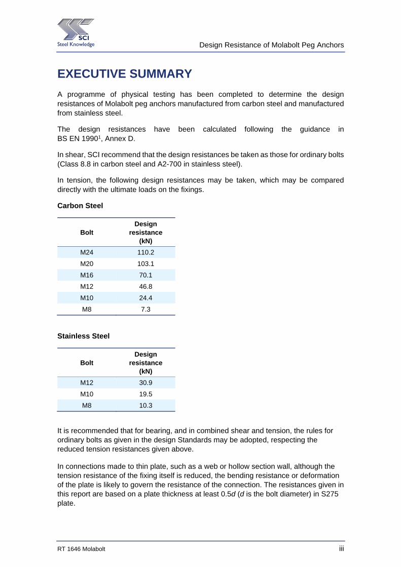
A programme of physical testing has been completed to determine the design resistances of Molabolt peg anchors manufactured from carbon steel and manufactured from stainless steel.
The design resistances have been calculated following the guidance in BS EN 19901, Annex D.
In shear, SCI recommend that the design resistances be taken as those for ordinary bolts (Class 8.8 in carbon steel and A2-700 in stainless steel).
In tension, the following design resistances may be taken, which may be compared directly with the ultimate loads on the fixings.
Carbon Steel
Bolt Design
resistance (kN)
M24 110.2
M20 103.1
M16 70.1
M12 46.8
M10 24.4
M8 7.3
Stainless Steel
Bolt Design
resistance (kN)
M12 30.9
M10 19.5
M8 10.3
It is recommended that for bearing, and in combined shear and tension, the rules for ordinary bolts as given in the design Standards may be adopted, respecting the reduced tension resistances given above.
In connections made to thin plate, such as a web or hollow section wall, although the tension resistance of the fixing itself is reduced, the bending resistance or deformation of the plate is likely to govern the resistance of the connection. The resistances given in this report are based on a plate thickness at least 0.5d (d is the bolt diameter) in S275 plate.

Design Resistance of Molabolt Peg Anchors
iv RT 1646 Molabolt
Design Resistance of Molabolt Peg Anchors
RT 1646 Molabolt v
Contents
Page No
EXECUTIVE SUMMARY iii
1 INTRODUCTION 1 1.1 Molabolt peg anchors 1 1.2 Design data to be determined 1 1.3 Development of test programme 2
2 TEST PROGRAMME 4
3 TEST RESULTS 6 3.1 Tension tests – carbon steel 6 3.2 Tension tests – stainless steel 7 3.3 Pull-out tests 8 3.4 Shear tests – carbon steel 8 3.5 Shear tests – stainless steel 9 3.6 Material properties 10
4 DETERMINATION OF DESIGN RESISTANCES 11 4.1 Resistances in tension 11 4.2 Pull-through in thin material 16 4.3 Resistances in shear 17 4.4 Recommended design values in shear 18 4.5 Bearing resistance 19 4.6 Combined tension and shear 19
5 RECOMMENDATIONS 21 5.1 Design resistances in tension 21 5.2 Design resistance in shear 21
REFERENCES 23
APPENDIX A TEST RESULTS 25 A.1 Tension tests 25 A.2 Pull-through tests in thin material 29
Design Resistance of Molabolt Peg Anchors
vi RT 1646 Molabolt
Design Resistance of Molabolt Peg Anchors
RT 1646 Molabolt 1
1 INTRODUCTION
Advance Bolting Solutions wish to present reliable design resistances for Molabolts, for design in accordance with BS 5950 and the Eurocodes. A series of physical tests have been completed and the design resistances determined by SCI, following the procedures in BS EN 19901.
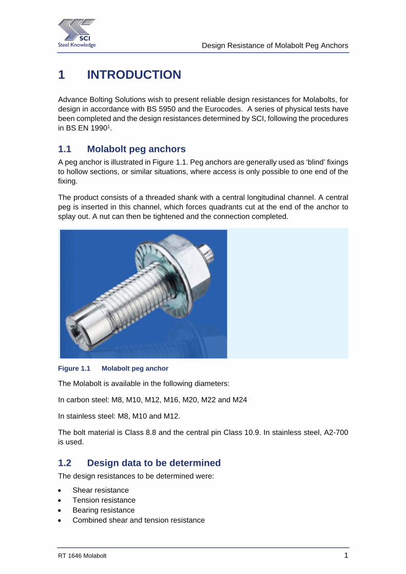
1.1 Molabolt peg anchors A peg anchor is illustrated in Figure 1.1. Peg anchors are generally used as ‘blind’ fixings to hollow sections, or similar situations, where access is only possible to one end of the fixing.
The product consists of a threaded shank with a central longitudinal channel. A central peg is inserted in this channel, which forces quadrants cut at the end of the anchor to splay out. A nut can then be tightened and the connection completed.
Figure 1.1 Molabolt peg anchor
The Molabolt is available in the following diameters:
In carbon steel: M8, M10, M12, M16, M20, M22 and M24
In stainless steel: M8, M10 and M12.
The bolt material is Class 8.8 and the central pin Class 10.9. In stainless steel, A2-700 is used.
1.2 Design data to be determined The design resistances to be determined were:
Shear resistance Tension resistance Bearing resistance Combined shear and tension resistance
Design Resistance of Molabolt Peg Anchors
2 RT 1646 Molabolt
1.3 Development of test programme The SCI proposed that the shear and tension resistances be determined from physical test. Although the shear plane passes through two separate components, of different grades, it was not anticipated that the shear resistance would be any less than for ordinary bolts.
In tension, the performance of a Molabolt was anticipated to differ from an ordinary bolt. More deformation was expected as the splayed end of the shank engages with the supporting plate and deforms under load. Deformation of the edge of the hole was also anticipated. Before testing, it was unclear if the splayed end of the Molabolt would perform as well as an ordinary bolt.
Intuitively, it was concluded that the thickness and grade of the supporting plate would have an impact on the resistance in tension. If the plate was very thin, it was assumed that the plate would deform before the fitting reached its full resistance. In reality, if the supporting plate was thin (as is typical for a connection to a hollow section) the resistance of the plate itself in bending would limit the resistance of the connection. Connections to hollow sections or other thin plates are limited either by deformation or by the resistance of the plate itself (typically determined by considering some form of yield line pattern). Nevertheless, it was felt prudent to undertake limited investigations of the effect of thin plate.
Bearing resistance was not considered in the tests, although general observations can be made from the shear test results. No tests were considered necessary since there was no expectation that the performance of the fixing would differ in any significant way from that of an ordinary bolt. The outside diameter is identical, and the circular central pin fills the void in the shank.
Combined shear and tension tests were not undertaken, as once the shear and tension tests had been used to establish resistances, it was considered that the interaction formulae in the design Standards would remain appropriate.
The test programme was arranged to cover large, intermediate and small diameter fixings, anticipating that design resistances could be interpolated for the remaining diameters.
Five samples were tested in each of the shear and tension tests. This population reflects the impact of Tables D1 and D2 of BS EN 1990, which effectively define the number of standard deviations below the mean which should be taken when determining design values. Although increasing the number of samples would have reduced the reduction from the mean, the beneficial effect becomes less significant
1.3.1 Modification of the test programme
As the testing proceeded, it became clear that in tension, there was a clear difference in behaviour between the larger bolts (which failed by fracture) and smaller diameters, which failed by a pull-through mode. This difference in behaviour implied that results could not be interpolated, and so additional tests were carried out, so that each bolt diameter was tested.
Additional tests were carried out on revised M16 carbon steel samples in October 2015.
Design Resistance of Molabolt Peg Anchors
RT 1646 Molabolt 3
Design Resistance of Molabolt Peg Anchors
4 RT 1646 Molabolt
2 TEST PROGRAMME
The physical testing was carried out by Intertek NDT of Derby.
All testing was completed in a test machine which could work in both tension and compression.
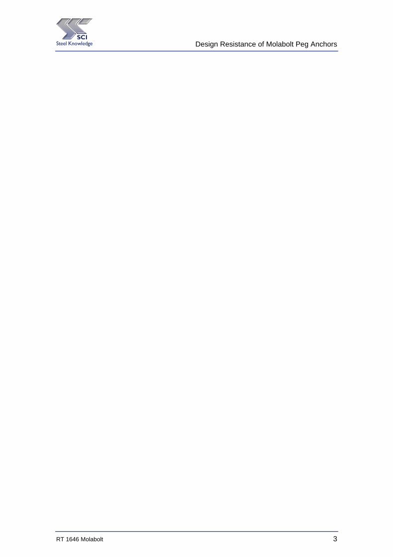
Tension tests were undertaken in a test rig shown in Figure 2.1. The test arrangement is effectively two U-shaped fabrications, with the test bolt connecting the two parts. The test machine acts in compression, which results in tension in the bolt.
Figure 2.1 Tension test arrangement
On the underside of the connection, sacrificial plates are used, drilled to the appropriate diameter for the bolt being tested. The test arrangement can therefore be used repeatedly.
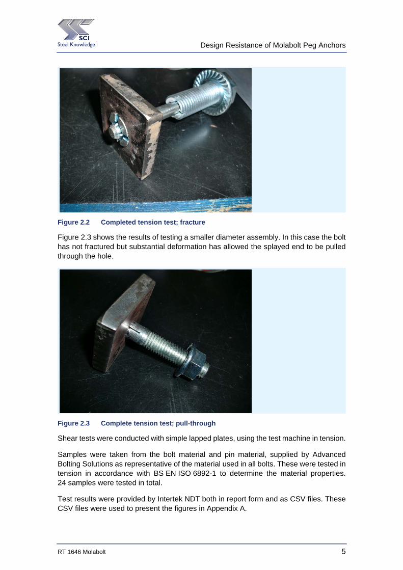
Figure 2.2 shows a completed tension test. The splayed ands of the Molabolt have been drawn into the sacrificial plate. The M20 bolt failed by fracture, as can be seen in the figure.
Design Resistance of Molabolt Peg Anchors
RT 1646 Molabolt 5
Figure 2.2 Completed tension test; fracture
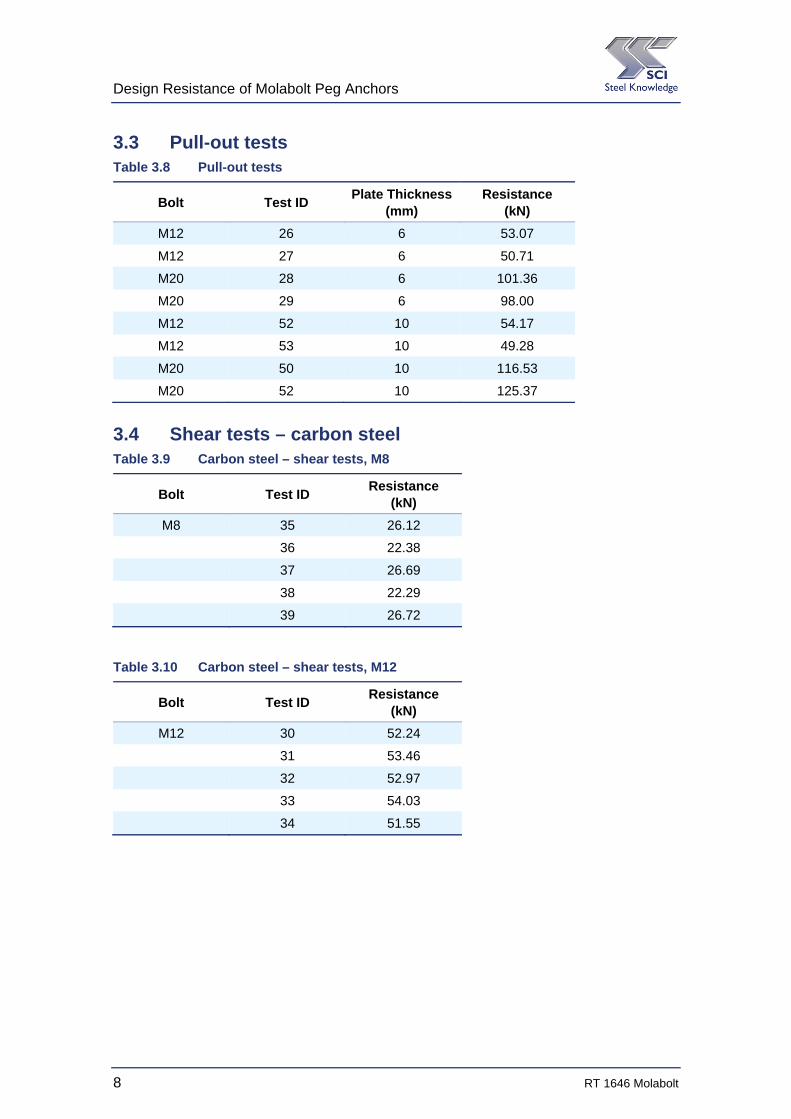
Figure 2.3 shows the results of testing a smaller diameter assembly. In this case the bolt has not fractured but substantial deformation has allowed the splayed end to be pulled through the hole.
Figure 2.3 Complete tension test; pull-through
Shear tests were conducted with simple lapped plates, using the test machine in tension.
Samples were taken from the bolt material and pin material, supplied by Advanced Bolting Solutions as representative of the material used in all bolts. These were tested in tension in accordance with BS EN ISO 6892-1 to determine the material properties. 24 samples were tested in total.
Test results were provided by Intertek NDT both in report form and as CSV files. These CSV files were used to present the figures in Appendix A.

Design Resistance of Molabolt Peg Anchors
6 RT 1646 Molabolt
3 TEST RESULTS
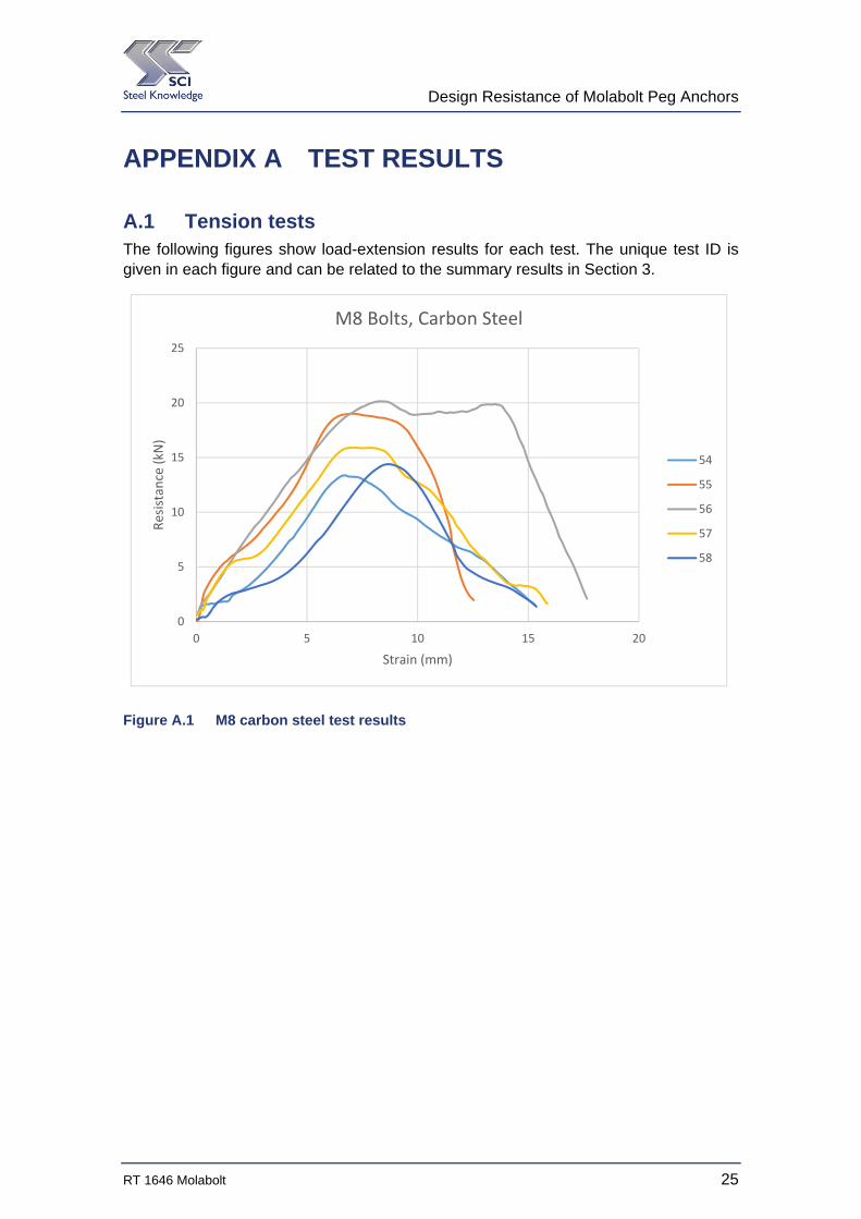
Test results are summarised in this section. The results have a unique test identification number, which may be used to cross reference these summary results to the detailed load-extension figures presented in Appendix A.
3.1 Tension tests – carbon steel Table 3.1 Carbon steel – tension tests, M8
Bolt Test ID Resistance
(kN)
M8 54 13.36
55 19.00
56 20.14
57 15.91
58 14.39
Table 3.2 Carbon steel – tension tests, M10
Bolt Test ID Resistance
(kN)
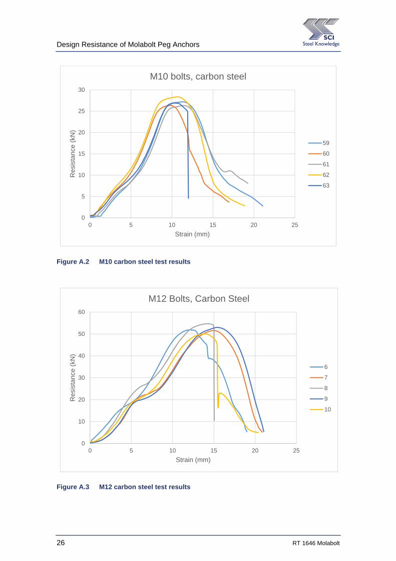
M10 59 27.18
60 26.38
61 26.31
62 28.35
63 26.90
Table 3.3 Carbon steel – tension tests, M12
Bolt Test ID Resistance
(kN)
M12 6 51.88
7 51.55
8 54.65
9 53.01
10 50.08

Design Resistance of Molabolt Peg Anchors
RT 1646 Molabolt 7
Table 3.4 Carbon steel – tension tests, M16
Bolt Test ID Resistance
(kN)
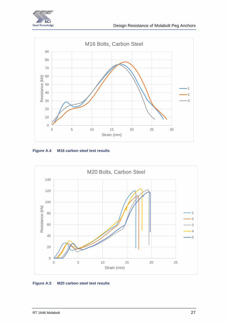
M16 NA 75.10
NA 77.63
NA 74.29
The tests in Table 3.4 are taken from Intertek report V091296E1/15 issue 2, dated 01 October 2015. The design of the assembly had been changed since the tests earlier in the year to follow the design of the M12 bolts.
Table 3.5 Carbon steel – tension tests, M20
Bolt Test ID Resistance
(kN)
M20 1 120.34
2 111.51
3 122.15
4 123.97
5 118.43
3.2 Tension tests – stainless steel Table 3.6 Stainless steel – tension tests, M8
Bolt Test ID Resistance
(kN)
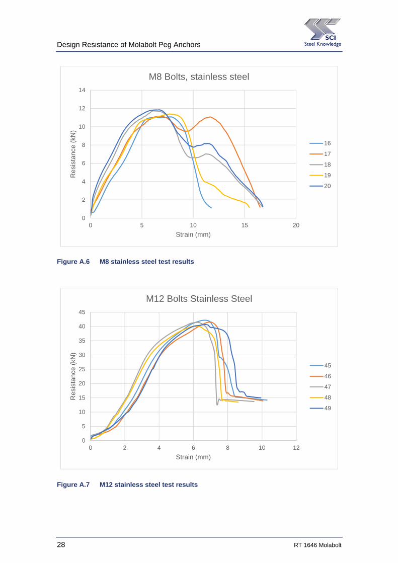
M8 16 11.07
17 11.14
18 11.73
19 11.39
20 11.84
Table 3.7 Stainless steel – tension tests, M12
Bolt Test ID Resistance
(kN)
M12 21 33.41
22 33.52
23 32.38
24 32.15
25 32.71
Design Resistance of Molabolt Peg Anchors
8 RT 1646 Molabolt
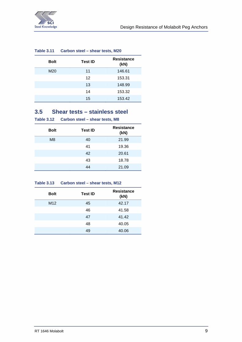
3.3 Pull-out tests Table 3.8 Pull-out tests
Bolt Test ID Plate Thickness
(mm) Resistance
(kN)
M12 26 6 53.07
M12 27 6 50.71
M20 28 6 101.36
M20 29 6 98.00
M12 52 10 54.17
M12 53 10 49.28
M20 50 10 116.53
M20 52 10 125.37
3.4 Shear tests – carbon steel Table 3.9 Carbon steel – shear tests, M8
Bolt Test ID Resistance
(kN)
M8 35 26.12
36 22.38
37 26.69
38 22.29
39 26.72
Table 3.10 Carbon steel – shear tests, M12
Bolt Test ID Resistance
(kN)
M12 30 52.24
31 53.46
32 52.97
33 54.03
34 51.55
Design Resistance of Molabolt Peg Anchors
RT 1646 Molabolt 9
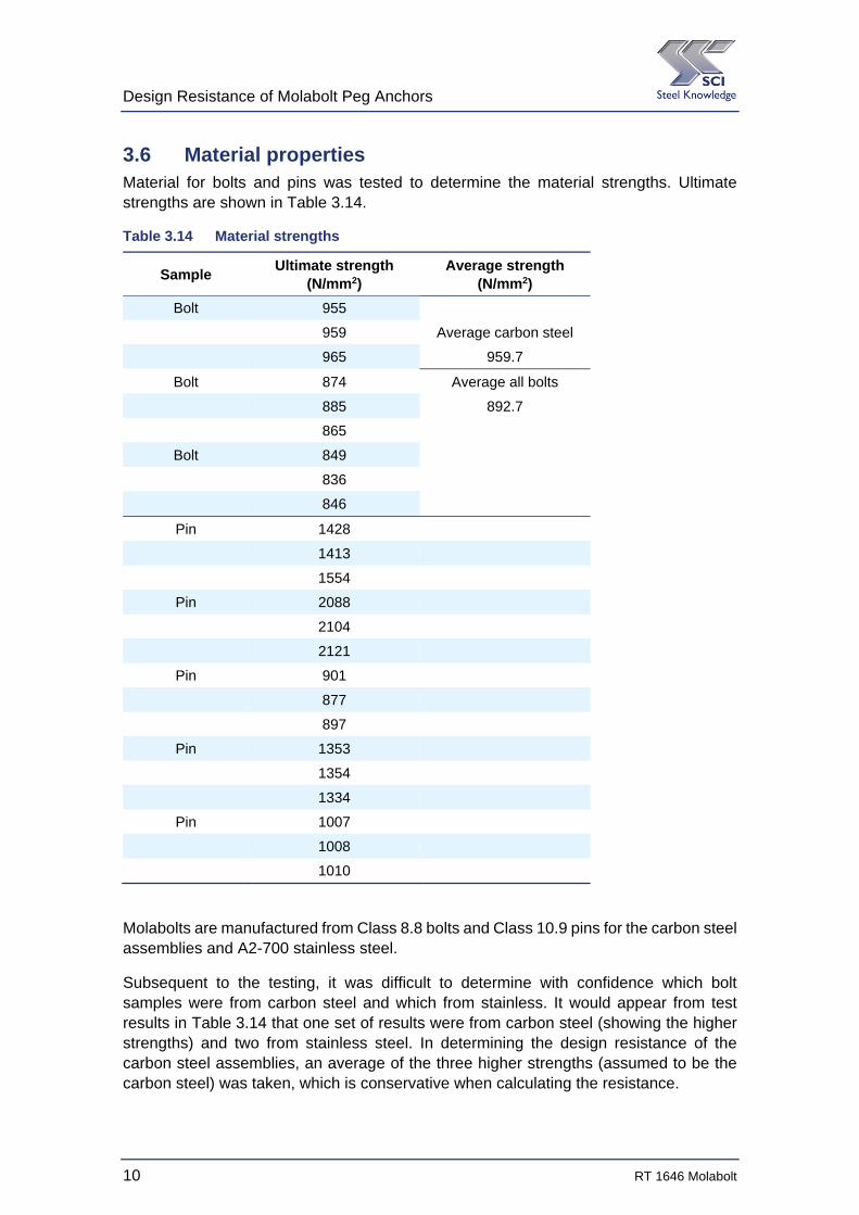
Table 3.11 Carbon steel – shear tests, M20
Bolt Test ID Resistance
(kN)
M20 11 146.61
12 153.31
13 148.99
14 153.32
15 153.42
3.5 Shear tests – stainless steel Table 3.12 Carbon steel – shear tests, M8
Bolt Test ID Resistance
(kN)
M8 40 21.99
41 19.36
42 20.61
43 18.78
44 21.09
Table 3.13 Carbon steel – shear tests, M12
Bolt Test ID Resistance
(kN)
M12 45 42.17
46 41.58
47 41.42
48 40.05
49 40.06
Design Resistance of Molabolt Peg Anchors
10 RT 1646 Molabolt
3.6 Material properties Material for bolts and pins was tested to determine the material strengths. Ultimate strengths are shown in Table 3.14.
Table 3.14 Material strengths
Sample Ultimate strength
(N/mm2) Average strength
(N/mm2)
Bolt 955
959 Average carbon steel
965 959.7
Bolt 874 Average all bolts
885 892.7
865
Bolt 849
836
846
Pin 1428
1413
1554
Pin 2088
2104
2121
Pin 901
877
897
Pin 1353
1354
1334
Pin 1007
1008
1010
Molabolts are manufactured from Class 8.8 bolts and Class 10.9 pins for the carbon steel assemblies and A2-700 stainless steel.
Subsequent to the testing, it was difficult to determine with confidence which bolt samples were from carbon steel and which from stainless. It would appear from test results in Table 3.14 that one set of results were from carbon steel (showing the higher strengths) and two from stainless steel. In determining the design resistance of the carbon steel assemblies, an average of the three higher strengths (assumed to be the carbon steel) was taken, which is conservative when calculating the resistance.
Design Resistance of Molabolt Peg Anchors
RT 1646 Molabolt 11
4 DETERMINATION OF DESIGN RESISTANCES
The procedure for determining resistances follows the guidance in Annex D of BS EN 1990.
Because prior knowledge exists of the performance of these assemblies (including earlier tests), the values of kn and kd,n from Tables D1 and D2 of Annex D have been based on “Vx known”.
When the behaviour under test is similar across bolt diameters, the value of n (the number of numerical test results) has been taken as that of the group, following the principle expressed in BS EN 1993-1-32 Clause A.6.3.2.
4.1 Resistances in tension Because two different forms of failure were observed during the test programme, a slightly different approach was followed in each case, as described in the following sections. In Sections 4.1.1, 4.1.2 and 4.1.3, the characteristic resistance of the M20 bolts is determined, so that a resistance value for the M24 can be determined, since the M24 and M20 bolts fail in the same manner.
In Section 4.1.4, the design resistance of M16 and smaller diameter bolts is determined from the test results for each diameter, as these bolts all fail by pull through the material.
In Section 4.1.5, a design resistance of M20 is determined directly from the test results.
4.1.1 M20 bolts failing in fracture
The M20 bolts failed in fracture. All the M20 bolts failed in this manner, which was sudden. The sudden failure can be seen in Figure A.5.
The fracture occurred at the cross section where the bolt shank is cut to produce the splayed end. As these cuts extend into the threaded portion of the shank, the fracture occurred at this minimum cross section.
For this type of failure, a simple mechanical model may be determined (see section 4.1.2) and the calculated resistances based on Table D1 of BS EN 1990. The measured resistances are firstly normalised with a correction factor based on the measured material properties. The mean and standard deviation for the five samples are determined and the characteristic resistance determined from:
Characteristic resistance = mean resistance – kn × standard deviation (taken from Table C3 of BS EN 1990 for a normal distribution)
In this case, as a mechanical design model is possible, kn = 1.8, from Table D1.
The average bolt material strength, as measured, is given in Table 3.14 as 959.7 N/mm2.
The nominal strength of Class 8.8 material, fub = 800 N/mm2, as given in Table 3.1 of
BS EN 1993-1-83. The correction factor is therefore 834.07.959800 .
Design Resistance of Molabolt Peg Anchors
12 RT 1646 Molabolt
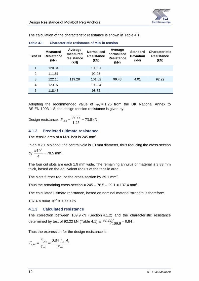
The calculation of the characteristic resistance is shown in Table 4.1.
Table 4.1 Characteristic resistance of M20 in tension
Test ID Measured
Resistance (kN)
Average measured resistance
(kN)
Normalised Resistance
(kN)
Average normalised Resistance
(kN)
Standard Deviation
(kN)
Characteristic Resistance
(kN)
1 120.34 100.31
2 111.51 92.95
3 122.15 119.28 101.82 99.43 4.01 92.22
4 123.97 103.34
5 118.43 98.72
Adopting the recommended value of M2 = 1.25 from the UK National Annex to BS EN 1993-1-8, the design tension resistance is given by:
Design resistance, kN8.7325.1
22.92Rdt, F
4.1.2 Predicted ultimate resistance
The tensile area of a M20 bolt is 245 mm2.
In an M20, Molabolt, the central void is 10 mm diameter, thus reducing the cross-section
by 4
10278.5 mm2.
The four cut slots are each 1.9 mm wide. The remaining annulus of material is 3.83 mm thick, based on the equivalent radius of the tensile area.
The slots further reduce the cross-section by 29.1 mm2.
Thus the remaining cross-section = 245 – 78.5 – 29.1 = 137.4 mm2.
The calculated ultimate resistance, based on nominal material strength is therefore:
137.4 × 800× 10-3 = 109.9 kN
4.1.3 Calculated resistance
The correction between 109.9 kN (Section 4.1.2) and the characteristic resistance
determined by test of 92.22 kN (Table 4.1) is 84.09.10922.92 .
Thus the expression for the design resistance is:
M2
tub
M2
Rkt,Rdt,
84.0
AfF
F
Design Resistance of Molabolt Peg Anchors
RT 1646 Molabolt 13
where:
fub is the nominal ultimate strength of the bolt
At is the (reduced) cross-sectional area
M2 = 1.25, as given by the UK National Annex to BS EN 1993-1-8
Note that this expression should only be applied to M20 bolts and larger, where the four cuts are run into the threaded shank, producing a fracture by failure of the cross-section.
For a M24 bolt, the tensile area is 353 mm2.
In an M24, Molabolt, the central void is 12.1 mm diameter, thus reducing the
cross-section by 4
1.12 2115 mm2.
The four cut slots are each 1.9 mm wide. The remaining annulus of material is 4.55 mm thick, based on the equivalent radius of the tensile area.
The slots further reduce the cross-section by 34.6 mm2.
Thus the remaining cross-section = 355 – 115 – 34.6 = 205.4 mm2.
The design shear resistance for a M24 Molabolt is therefore:
3
M2
Rkt,Rdt, 10
25.1
20580084.0
F
F = 110.2 kN
4.1.4 M16 and smaller bolts failing by pull-through – carbon steel
M16 bolts and smaller diameters fail by pull through rather than fracture of the bolt assembly. This behaviour can be seen in the load-extension plots for M8, M10, M12 and M16 bolts seen in Figure A.1 to Figure A.4.
There is no mechanical design model for a pull through failure, as this is complex behaviour. Therefore the design values of resistance have been calculated directly from the test results, using Table D2 of BS EN 1990.
The design values of resistance have been calculated as follows:
Design value of resistance = mean resistance – kd,n × standard deviation (taken from Table C3 of BS EN 1990 for a normal distribution)
From Table D2, kd,n has been taken as 3.174, for a family of 18 tests and “Vx known”
Design resistances are calculated in the following tables.

Design Resistance of Molabolt Peg Anchors
14 RT 1646 Molabolt
Table 4.2 Design value of resistance of M8 in tension
Test ID Measured
Resistance (kN)
Average Resistance
(kN)
Standard Deviation
(kN)
Design Value of Resistance
(kN)
54 13.36
55 19.00
56 20.14 16.56 2.92 7.3
57 15.91
58 14.39
It should be noted that considerable scatter is observed in the test results for M8 bolts. The coefficient of variation (standard deviation/mean) = 17.6%, compared to generally less than 4% for other bolt diameters.
Table 4.3 Design value of resistance of M10 in tension
Test ID Measured
Resistance (kN)
Average Resistance
(kN)
Standard Deviation
(kN)
Design Value of Resistance
(kN)
59 27.18
60 26.38
61 26.31 27.02 0.83 24.4
62 28.35
63 26.90
Table 4.4 Design value of resistance of M12 in tension
Test ID Measured
Resistance (kN)
Average Resistance
(kN)
Standard Deviation
(kN)
Design Value of Resistance
(kN)
6 51.88
7 51.55
8 54.65 52.23 1.71 46.8
9 53.01
10 50.08
Design Resistance of Molabolt Peg Anchors
RT 1646 Molabolt 15
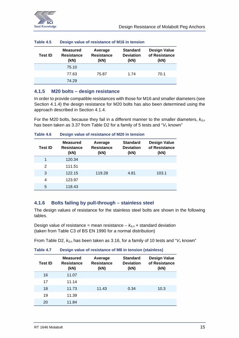
Table 4.5 Design value of resistance of M16 in tension
Test ID Measured
Resistance (kN)
Average Resistance
(kN)
Standard Deviation
(kN)
Design Value of Resistance
(kN)
75.10
77.63 75.87 1.74 70.1
74.29
4.1.5 M20 bolts – design resistance
In order to provide compatible resistances with those for M16 and smaller diameters (see Section 4.1.4) the design resistance for M20 bolts has also been determined using the approach described in Section 4.1.4.
For the M20 bolts, because they fail in a different manner to the smaller diameters, kd,n has been taken as 3.37 from Table D2 for a family of 5 tests and “Vx known”
Table 4.6 Design value of resistance of M20 in tension
Test ID Measured
Resistance (kN)
Average Resistance
(kN)
Standard Deviation
(kN)
Design Value of Resistance
(kN)
1 120.34
2 111.51
3 122.15 119.28 4.81 103.1
4 123.97
5 118.43
4.1.6 Bolts failing by pull-through – stainless steel
The design values of resistance for the stainless steel bolts are shown in the following tables.
Design value of resistance = mean resistance – kd,n × standard deviation (taken from Table C3 of BS EN 1990 for a normal distribution)
From Table D2, kd,n has been taken as 3.16, for a family of 10 tests and “Vx known”
Table 4.7 Design value of resistance of M8 in tension (stainless)
Test ID Measured
Resistance (kN)
Average Resistance
(kN)
Standard Deviation
(kN)
Design Value of Resistance
(kN)
16 11.07
17 11.14
18 11.73 11.43 0.34 10.3
19 11.39
20 11.84
Design Resistance of Molabolt Peg Anchors
16 RT 1646 Molabolt
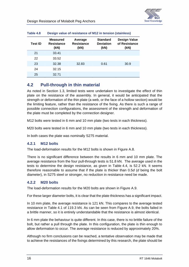
Table 4.8 Design value of resistance of M12 in tension (stainless)
Test ID Measured
Resistance (kN)
Average Resistance
(kN)
Standard Deviation
(kN)
Design Value of Resistance
(kN)
21 33.41
22 33.52
23 32.38 32.83 0.61 30.9
24 32.15
25 32.71
4.2 Pull-through in thin material As noted in Section 1.3, limited tests were undertaken to investigate the effect of thin plate on the resistance of the assembly. In general, it would be anticipated that the strength or deformation of the thin plate (a web, or the face of a hollow section) would be the limiting feature, rather than the resistance of the fixing. As there is such a range of possible connection configurations, the assessment of the strength and deformation of the plate must be completed by the connection designer.
M12 bolts were tested in 6 mm and 10 mm plate (two tests in each thickness).
M20 bolts were tested in 6 mm and 10 mm plate (two tests in each thickness).
In both cases the plate was nominally S275 material.
4.2.1 M12 bolts
The load-deformation results for the M12 bolts is shown in Figure A.8.
There is no significant difference between the results in 6 mm and 10 mm plate. The average resistance from the four pull-through tests is 51.8 kN. The average used in the tests to determine the design resistance, as given in Table 4.4, is 52.2 kN. It seems therefore reasonable to assume that if the plate is thicker than 0.5d (d being the bolt diameter), in S275 steel or stronger, no reduction in resistance need be made.
4.2.2 M20 bolts
The load-deformation results for the M20 bolts are shown in Figure A.9.
For these larger diameter bolts, it is clear that the plate thickness has a significant impact.
In 10 mm plate, the average resistance is 121 kN. This compares to the average tested resistance in Table 4.1 of 119.3 kN. As can be seen from Figure A.9, the bolts failed in a brittle manner, so it is entirely understandable that the resistance is almost identical.
In 6 mm plate the behaviour is quite different. In this case, there is no brittle failure of the bolt, but rather a pull through the plate. In this configuration, the plate is thin enough to allow deformation to occur. The average resistance is reduced by approximately 20%.
Although no firm conclusions can be reached, a tentative observation may be made that to achieve the resistances of the fixings determined by this research, the plate should be
Design Resistance of Molabolt Peg Anchors
RT 1646 Molabolt 17
at least 0.5d and at least grade S275. In most situations, the design resistance would be limited by the strength or deformation of the plate, not the fixing.
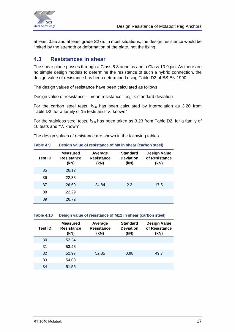
4.3 Resistances in shear The shear plane passes through a Class 8.8 annulus and a Class 10.9 pin. As there are no simple design models to determine the resistance of such a hybrid connection, the design value of resistance has been determined using Table D2 of BS EN 1990.
The design values of resistance have been calculated as follows:
Design value of resistance = mean resistance – kd,n × standard deviation
For the carbon steel tests, kd,n has been calculated by interpolation as 3.20 from Table D2, for a family of 15 tests and “Vx known”
For the stainless steel tests, kd,n has been taken as 3.23 from Table D2, for a family of 10 tests and “Vx known”
The design values of resistance are shown in the following tables.
Table 4.9 Design value of resistance of M8 in shear (carbon steel)
Test ID Measured
Resistance (kN)
Average Resistance
(kN)
Standard Deviation
(kN)
Design Value of Resistance
(kN)
35 26.12
36 22.38
37 26.69 24.84 2.3 17.5
38 22.29
39 26.72
Table 4.10 Design value of resistance of M12 in shear (carbon steel)
Test ID Measured
Resistance (kN)
Average Resistance
(kN)
Standard Deviation
(kN)
Design Value of Resistance
(kN)
30 52.24
31 53.46
32 52.97 52.85 0.98 49.7
33 54.03
34 51.55
Design Resistance of Molabolt Peg Anchors
18 RT 1646 Molabolt
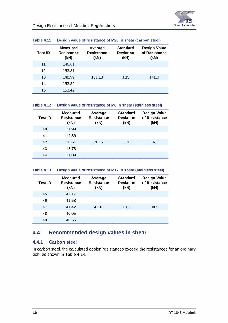
Table 4.11 Design value of resistance of M20 in shear (carbon steel)
Test ID Measured
Resistance (kN)
Average Resistance
(kN)
Standard Deviation
(kN)
Design Value of Resistance
(kN)
11 146.61
12 153.31
13 148.99 151.13 3.15 141.0
14 153.32
15 153.42
Table 4.12 Design value of resistance of M8 in shear (stainless steel)
Test ID Measured
Resistance (kN)
Average Resistance
(kN)
Standard Deviation
(kN)
Design Value of Resistance
(kN)
40 21.99
41 19.36
42 20.61 20.37 1.30 16.2
43 18.78
44 21.09
Table 4.13 Design value of resistance of M12 in shear (stainless steel)
Test ID Measured
Resistance (kN)
Average Resistance
(kN)
Standard Deviation
(kN)
Design Value of Resistance
(kN)
45 42.17
46 41.58
47 41.42 41.18 0.83 38.5
48 40.05
49 40.66
4.4 Recommended design values in shear
4.4.1 Carbon steel
In carbon steel, the calculated design resistances exceed the resistances for an ordinary bolt, as shown in Table 4.14.
Design Resistance of Molabolt Peg Anchors
RT 1646 Molabolt 19
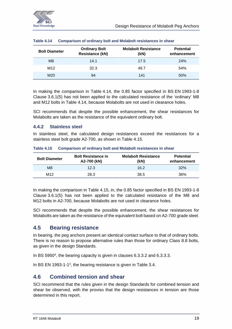
Table 4.14 Comparison of ordinary bolt and Molabolt resistances in shear
Bolt Diameter Ordinary Bolt
Resistance (kN) Molabolt Resistance
(kN) Potential
enhancement
M8 14.1 17.5 24%
M12 32.3 49.7 54%
M20 94 141 50%
In making the comparison in Table 4.14, the 0.85 factor specified in BS EN 1993-1-8 Clause 3.6.1(5) has not been applied to the calculated resistance of the ‘ordinary’ M8 and M12 bolts in Table 4.14, because Molabolts are not used in clearance holes.
SCI recommends that despite the possible enhancement, the shear resistances for Molabolts are taken as the resistance of the equivalent ordinary bolt.
4.4.2 Stainless steel
In stainless steel, the calculated design resistances exceed the resistances for a stainless steel bolt grade A2-700, as shown in Table 4.15.
Table 4.15 Comparison of ordinary bolt and Molabolt resistances in shear
Bolt Diameter Bolt Resistance in
A2-700 (kN) Molabolt Resistance
(kN) Potential
enhancement
M8 12.3 16.2 32%
M12 28.3 38.5 36%
In making the comparison in Table 4.15, in, the 0.85 factor specified in BS EN 1993-1-8 Clause 3.6.1(5) has not been applied to the calculated resistance of the M8 and M12 bolts in A2-700, because Molabolts are not used in clearance holes.
SCI recommends that despite the possible enhancement, the shear resistances for Molabolts are taken as the resistance of the equivalent bolt based on A2-700 grade steel.
4.5 Bearing resistance In bearing, the peg anchors present an identical contact surface to that of ordinary bolts. There is no reason to propose alternative rules than those for ordinary Class 8.8 bolts, as given in the design Standards.
In BS 59504, the bearing capacity is given in clauses 6.3.3.2 and 6.3.3.3.
In BS EN 1993-1-13, the bearing resistance is given in Table 3.4.
4.6 Combined tension and shear SCI recommend that the rules given in the design Standards for combined tension and shear be observed, with the proviso that the design resistances in tension are those determined in this report.
Design Resistance of Molabolt Peg Anchors
20 RT 1646 Molabolt
In BS 59504, the rule is given in clause 6.3.4.4.
In BS EN 1993-1-83, the rule is given in Table 3.4
Design Resistance of Molabolt Peg Anchors
RT 1646 Molabolt 21
5 RECOMMENDATIONS
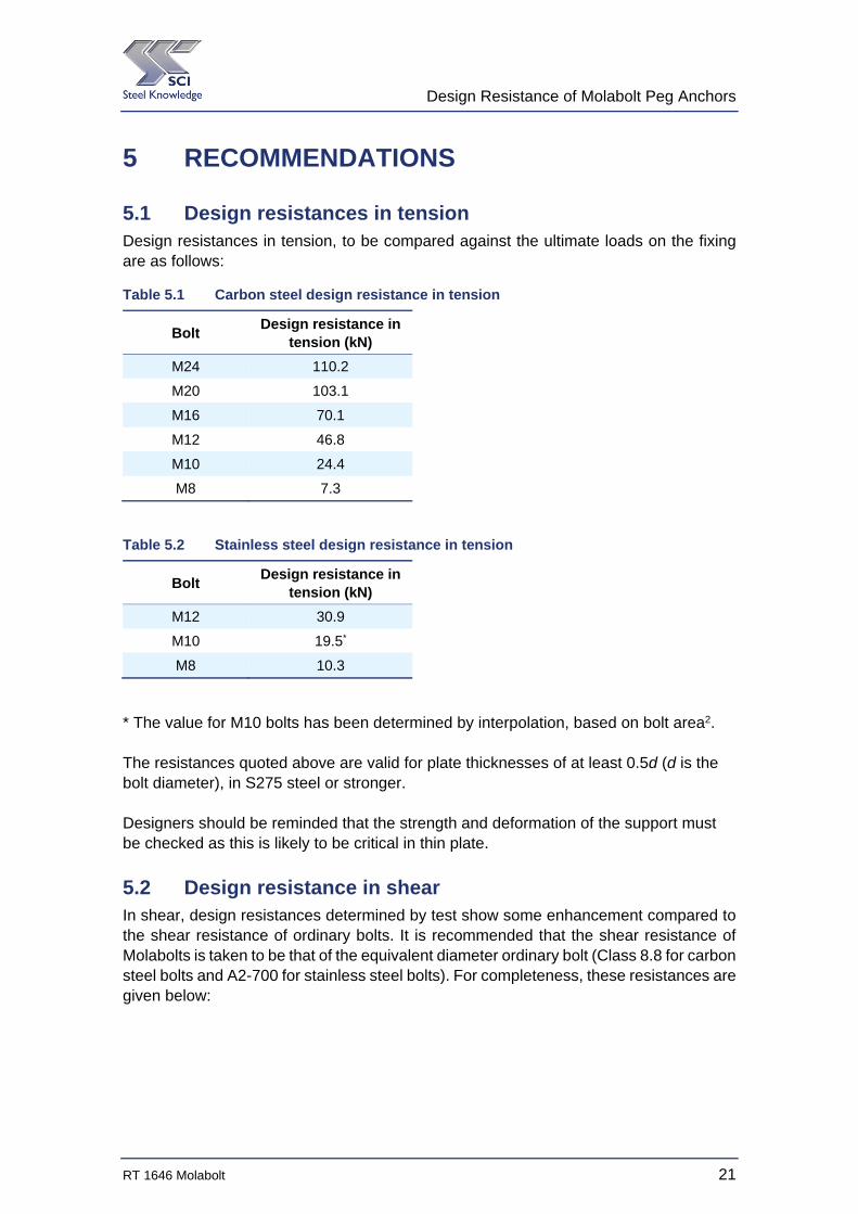
5.1 Design resistances in tension Design resistances in tension, to be compared against the ultimate loads on the fixing are as follows:
Table 5.1 Carbon steel design resistance in tension
Bolt Design resistance in
tension (kN)
M24 110.2
M20 103.1
M16 70.1
M12 46.8
M10 24.4
M8 7.3
Table 5.2 Stainless steel design resistance in tension
Bolt Design resistance in
tension (kN)
M12 30.9
M10 19.5*
M8 10.3
* The value for M10 bolts has been determined by interpolation, based on bolt area2. The resistances quoted above are valid for plate thicknesses of at least 0.5d (d is the bolt diameter), in S275 steel or stronger. Designers should be reminded that the strength and deformation of the support must be checked as this is likely to be critical in thin plate.
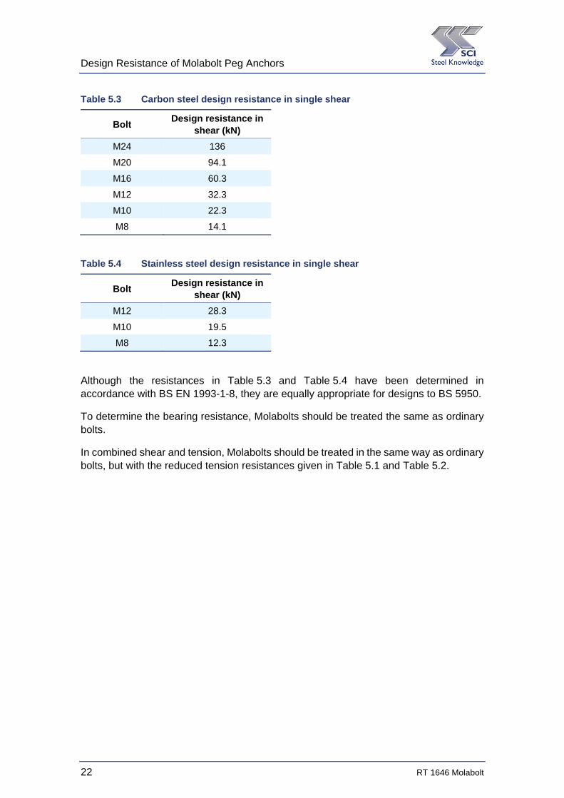
5.2 Design resistance in shear In shear, design resistances determined by test show some enhancement compared to the shear resistance of ordinary bolts. It is recommended that the shear resistance of Molabolts is taken to be that of the equivalent diameter ordinary bolt (Class 8.8 for carbon steel bolts and A2-700 for stainless steel bolts). For completeness, these resistances are given below:
Design Resistance of Molabolt Peg Anchors
22 RT 1646 Molabolt
Table 5.3 Carbon steel design resistance in single shear
Bolt Design resistance in
shear (kN)
M24 136
M20 94.1
M16 60.3
M12 32.3
M10 22.3
M8 14.1
Table 5.4 Stainless steel design resistance in single shear
Bolt Design resistance in
shear (kN)
M12 28.3
M10 19.5
M8 12.3
Although the resistances in Table 5.3 and Table 5.4 have been determined in accordance with BS EN 1993-1-8, they are equally appropriate for designs to BS 5950.
To determine the bearing resistance, Molabolts should be treated the same as ordinary bolts.
In combined shear and tension, Molabolts should be treated in the same way as ordinary bolts, but with the reduced tension resistances given in Table 5.1 and Table 5.2.
Design Resistance of Molabolt Peg Anchors
RT 1646 Molabolt 23
REFERENCES
1 BS EN 1990:2002 + A1:2005 Eurocode – Basis of structural design
2 BS EN 1993-1-3:2006 Eurocode 3- Design of steel structures – Part 1-3: General rules – Supplementary rules for cold-formed members and sheeting
3 BS EN 1993-1-8:2005 Eurocode 3: Design of steel structures – Part 1-8: Design of joints
4 BS 5950-1:2000 Structural use of steelwork in building – Part 1: Code of practice for design – Rolled and welded sections

Design Resistance of Molabolt Peg Anchors
24 RT 1646 Molabolt
Design Resistance of Molabolt Peg Anchors
RT 1646 Molabolt 25
APPENDIX A TEST RESULTS
A.1 Tension tests The following figures show load-extension results for each test. The unique test ID is given in each figure and can be related to the summary results in Section 3.
Figure A.1 M8 carbon steel test results
0
5
10
15
20
25
0 5 10 15 20
Resistance (kN
)
Strain (mm)
M8 Bolts, Carbon Steel
54
55
56
57
58
Design Resistance of Molabolt Peg Anchors
26 RT 1646 Molabolt
Figure A.2 M10 carbon steel test results
Figure A.3 M12 carbon steel test results
0
5
10
15
20
25
30
0 5 10 15 20 25
Res
ista
nce
(kN
)
Strain (mm)
M10 bolts, carbon steel
59
60
61
62
63
0
10
20
30
40
50
60
0 5 10 15 20 25
Res
ista
nce
(kN
)
Strain (mm)
M12 Bolts, Carbon Steel
6
7
8
9
10
Design Resistance of Molabolt Peg Anchors
RT 1646 Molabolt 27
Figure A.4 M16 carbon steel test results
Figure A.5 M20 carbon steel test results
0
10
20
30
40
50
60
70
80
90
0 5 10 15 20 25 30
Res
ista
nce
(kN
)
Strain (mm)
M16 Bolts, Carbon Steel
1
2
3
0
20
40
60
80
100
120
140
0 5 10 15 20 25
Res
ista
nce
(kN
)
Strain (mm)
M20 Bolts, Carbon Steel
1
2
3
4
5
Design Resistance of Molabolt Peg Anchors
28 RT 1646 Molabolt
Figure A.6 M8 stainless steel test results
Figure A.7 M12 stainless steel test results
0
2
4
6
8
10
12
14
0 5 10 15 20
Res
ista
nce
(kN
)
Strain (mm)
M8 Bolts, stainless steel
16
17
18
19
20
0
5
10
15
20
25
30
35
40
45
0 2 4 6 8 10 12
Res
ista
nce
(kN
)
Strain (mm)
M12 Bolts Stainless Steel
45
46
47
48
49

Design Resistance of Molabolt Peg Anchors
RT 1646 Molabolt 29
A.2 Pull-through tests in thin material
Figure A.8 M12 pull-through tests
Figure A.9 M20 pull-through tests
0
10
20
30
40
50
60
0 5 10 15 20 25
Resistance (kN
)
Strain (mm)
Pull through tests ‐M12
M12 in 6 mm (1)
M12 in 6 mm (2)
M12 in 10 mm (1)
M12 in 10 mm (2)
0
20
40
60
80
100
120
140
0 5 10 15 20 25 30 35
Resistance (kN
)
Strain (mm)
Pull through tests ‐M20
M20 in 6 mm (1)
M20 in 6 mm (2)
M20 in 10 mm (1)
M20 in 10 mm (2)

Design Resistance of Molabolt Peg Anchors
30 RT 1646 Molabolt