design regulations bkr
DESCRIPTION
Sweden building codesTRANSCRIPT

BFS 1993:58 with amendments up to BFS 1998:39,
BFS 1999:7 and BFS 1999:46
DESIGN REGULATIONS
BKR
Mandatory provisions and
general recommendations The following translation is strictly for informa-tive purposes. The legally binding text is found in the Code of Statutes of the Swedish National Board of Housing, Building and Planning
Swedish Board of Housing, Building and Planning

Reg.No.: B6081-2236/96 Title: Design Regulations of Swedish Board of Housing, Building and Planning, BKR. Published by: Swedish Board of Housing, Building and Planning Month of publication: June 2000 Edition: 2:1 Number: 300 Printed by: Swedish Board of Housing, Building and Planning ISBN: 91-7147-616-4 ISSN: 1100 0856 Summary: This reprint of Design Regulations, BKR, of the Swedish Board of Housing, Building and Planning contains mandatory provisions and general recom-mendations pursuant to the Planning and Building Act (1987:10), PBL, the Act on Technical Requirements for Construction Works etc (1994:847) and the Decree on Technical Requirements for Construction Works etc (1994:1215). This edition of BKR has inter alia been adapted to new and amended standards. Other important changes are the new classification of frost resistance of bricks and the introduction of Class D Mortar. Necessary clarifications and some other adjust-ments have also been made. Key words: Building regulations, design regulations, regulations for new buildings, mandatory provisions, general recommendations, structures, resistance, durability, strength, actions, design, geotechnics, stability, timber structures, masonry, concrete structures, steel structures, aluminium structures, fire resistance, properties, supervision and control, calculation methods, formulae, planning and building act, act on technical requirements for construction works etc, the properties of buildings, BBR 94, BKR 94, BBR, BKR, NR, PBL, BVL, BFS. The publication can be ordered from: Swedish Board of Housing, Building and Planning Publication Service Box 534 S-371 23 Karlskrona, Sweden Fax: +46 455 819 27 E-mail: [email protected] Boverket, 2000 Translated by L J Gruber BSc(Eng) CEng MICE MIStructE, Lars Albrektsson Layout: Anthoinette Åberg

Contents BFS 1998:39
3
CONTENTS 1 INTRODUCTION 13
1:1 General 13
1:2 Mandatory provisions 13
1:3 General recommendations 14
1:4 Type approval and production control 14
1:5 Standards 15
1:6 Terminology 15
1:7 Further information 15 2 GENERAL REGULATIONS FOR LOADBEARING STRUCTURES 17
2:1 Requirements 17
2:11 Requirements in the ultimate limit states 17 :111 Material failure and instability 17 :112 Tilting, uplift and sliding 17 :113 Accidental actions and progressive collapse 17 :114 Safety index 18 :115 Safety classes 18 2:12 Requirements in the serviceability limit states 21 :121 Deformation and displacement 21 :122 Oscillations 22 :123 Cracking 22 2:13 Durability 22
2:2 Design assumptions 22
2:21 Actions and combinations of actions 22 2:22 Materials 24 2:23 Deviations in size and shape 24
2:3 Design by calculation and testing 24
2:31 Calculation 24 2:32 The method of partial factors 25 :321 Design combination of actions 26 :322 Design values of material properties 28 2:33 Design by testing 29 2:34 Documentation 29
2:4 Materials 29
2:5 Design and execution 30
2:6 Supervision and control 30 2:61 Design checks 30

BFS 1998:39 Contents
4
2:62 Acceptance inspection and supervision of construction 30 :621 Basic inspection and additiona l inspection 31 2:63 Documentation 31 3 ACTIONS 33
3:1 The self weight of elements of structure 33
3:2 Earth load and earth pressure 33
3:3 Water pressure 34
3:4 Imposed load 35
3:41 Load due to fittings, fixtures and persons 35 3:42 Load due to piece goods, bulk goods and silo pressure 39 3:43 Load due to vehicles, materials handling equipment 40 and machinery :431 Load due to vehicles 40 :432 Load due to cranes, overhead travelling cranes and 41 similar :433 Load due to machinery and similar 42 :434 Load due to lift machinery and similar 43
3:5 Snow load 43
3:6 Wind action 45
3:7 Pressure due to ice and water currents 48
3:8 Deformation action and accidental actions 48 4 GEOSTRUCTURES 49
4:1 Requirements 49
4:2 Design assumptions 49
4:21 Geotechnical categories (GK) 49 4:22 Geotechnical investigation 51 4:23 Characteristic values 52 4:24 Tolerances 52 4:25 Durability 52
4:3 Design by calculation and testing 53
4:31 Design in the ultimate limit states 53 :311 Earth pressure 54 :3111 Geotechnical category 1 (GK 1) 54 :312 Foundation slabs 55 :3121 Geotechnical category 1 (GK 1) 55 :3122 Geotechnical category 2 (GK 2) and geotechnical category 3 (GK 3) 57 :313 Piles 57 :3131 Geotechnical category 1 (GK 1) 57 :3132 Geotechnical category 2 (GK 2) and geotechnical category 3 (GK 3) 58 4:32 Design in the serviceability limit states 58 4:33 Design by testing 59

Contents BFS 1998:39
5
4:4 Materials 60
4:5 Execution and workmanship 60
4:6 Supervision and control 60 5 TIMBER STRUCTURES 61
5:1 Requirements 61
5:11 Durability 61
5:2 Design assumptions 61
5:21 Service classes 61 5:22 The duration of actions 61 5:23 Characteristic values for wood based materials 62 5:24 Characteristic loadcarrying capacity of timber joints 67 :241 Nailed joints subject to shear force 67 :242 Nailed joints subject to withdrawal force 69 :243 Bolted joints subject to shear force 70 :244 Screwed joints subject to shear force 71 :245 Screwed joints subject to withdrawal force 72 :246 Glued joints 72
5:3 Design by calculation and testing 72
5:31 Design in the ultimate limit states 73 :311 Calculation of forces and moments 73 :312 Calculation of resistance 73 :3121 Design values of material properties 74 :3122 Tension 77 :3123 Compression 77 :3124 Bending 79 :3125 Shear 80 :3126 Combined axial tension and bending 80 :3127 Combined axial compression and bending 80 5:32 Design in the serviceability limit states 81 :321 Calculation of forces and moments 81 :322 Design values of material properties 82 :323 Floor vibration 83 5:33 Design by testing 83
5:4 Materials 84
5:41 Structural timber 84 :411 Visually graded structural timber 84 :412 Mechanically stress graded structural timber 85 :413 Finger jointed structural timber 85 :414 Round timber 85 :415 Glued structural timber 86 5:42 Glued laminated timber 86 5:43 Structural board 86 5:44 Joints 86 :441 Mechanical connectors 86 :442 Adhesives 87
5:5 Execution and workmanship 87
5:51 Timber 87 5:52 Joints 88 :521 Nailed joints 88

BFS 1998:39 Contents
6
:522 Punched nail plate joints 88 :523 Bolted and screwed joints 88 :524 Glued joints 88
5:6 Supervision and control 88
5:61 Basic inspection 88 5:62 Additional inspection 89 6 MASONRY STRUCTURES 91
6:1 Requirements 91
6:11 Durability 91
6:2 Design assumptions 92
6:21 Characteristic values of material properties for masonry structures 92 :211 Compressive strength 92 :212 Flexural tensile strength 95 :213 Shear strength 96 :214 Modulus of elasticity 97 6:22 Deviations from size and shape 97
6:3 Design by calculation and testing 97
6:31 Design in the ultimate limit states 97 :311 Calculation of forces and moments 97 :312 Calculation of resistance 98 :3121 Design values of material properties for masonry 98 :3122 Design values of material properties for reinforcement 99 :3123 Partial factor for masonry, wall ties and reinforcement 99 :3124 Stress-strain curves 100 :3125 Masonry acted upon by vertical actions 101 :3126 Masonry acted upon by transverse actions 101 :3127 Local pressure 102 :3128 Reinforced masonry 102 :3129 Wall ties in veneer walls 105 6:32 Design in the serviceability limit states 106 :321 Design values of material properties 106 :322 Deformation and cracking 106 6:33 Design by testing 107
6:4 Materials 107
6:41 Bricks and blocks 108 6:42 Mortar 109 6:43 Thin joint mortar 110 6:44 Wall ties 110 6:45 Reinforcement 111
6:5 Execution and workmanship 111
6:51 Masonry work 111
6:6 Supervision and control 112
6:61 Acceptance inspection on delivery 112 :611 Basic inspection 112 6:62 Supervision of execution and workmanship 115 :621 Basic inspection 115 :622 Additional inspection 115

Contents BFS 1998:39
7
7 CONCRETE STRUCTURES 117
7:1 Requirements 117
7:11 Durability 117 7:12 Watertightness 117
7:2 Design assumptions 118
7:21 Actions 118 7:22 Characteristic values of material properties for concrete 118 :221 Compressive strength 118 :222 Tensile strength 119 :223 Modulus of elasticity 120 7:23 Characteristic values of material properties for reinforcing and prestressing steel 121 :231 Tensile strength 121 :232 Modulus of elasticity 122 7:24 Prestressing forces 122 7:25 Deviations in size and shape 122
7:3 Design by calculation and testing 123
7:31 Design in the ultimate limit states 123 :311 Calculation of forces and moments 123 :312 Calculation of resistance 124 :3121 Design values of material properties 124 :3122 Fatigue 126 :3123 Stress-strain curves 126 :3124 Creep and shrinkage of concrete 126 :3125 Prestressing forces and relaxations 127 :3126 Bending moment with or without longitudinal force 127 :3127 Shear force and torsional moment 128 :3128 Anchorage and arrangement of reinforcement 128 :3129 Local pressure and transmission of force through joints 129 7:32 Design in the serviceability limit states 130 7:33 Design by testing 131 7:34 Documentation 131
7:4 Materials 132
7:41 Materials for concrete 132 7:42 Concrete mix 132 7:43 Reinforcement, prestressing tendons and embedded fasteners 132
7:5 Execution and workmanship 133
7:51 Manufacture of the concrete mix 133 7:52 Work with concrete 133 7:53 Construction and removal of formwork 134 7:54 Reinforcement and prestressing tendons 134 7:55 Precast concrete units 135 7:56 Special concreting procedures 135
7:6 Supervision and control 135
7:61 General 136 :611 Basic inspection 136 :612 Additional inspection 136 7:62 Acceptance inspection of concrete on delivery 136

BFS 1998:39 Contents
8
7:63 Acceptance inspection of reinforcement and prestressing tendons on delivery 136 7:64 Acceptance inspection of precast concrete units 137 7:65 Supervision of execution and workmanship 137
8 STEEL STRUCTURES 139
8:1 Requirements 139
8:11 Ductility 139 8:12 Durability 139
8:2 Design assumptions 139
8:21 Actions 139 8:22 Characteristic values 140 :221 Values of strength 140 :222 Values of strength in conjunction with fatigue action 142 :223 Modulus of elasticity, shear modulus and Poisson's ratio 143 :224 Bolted connections 143 :225 Welded connections 143 :226 Deviations in size and shape 144
8:3 Design by calculation and testing 144
8:31 Design in the ultimate limit states 145 :311 Calculation of forces and moments 145 :312 Calculation of resistance 145 :3121 Residual stresses 146 :3122 Fatigue 147 :3123 Shell structures 147 :3124 Bolted connections 147 :3125 Welded connections 148 8:32 Design in the serviceability limit states 148 8:33 Design by testing 148
8:4 Materials 149
8:41 Bolted connections 149 8:42 Filler metal 149 8:43 Properties in the thickness direction 150
8:5 Execution and workmanship 150
8:51 Handling of materials 150 8:52 Preparation of materials 150 8:53 Welded connections 150 :531 Welding 150 :532 Welding procedure sheet 151 :533 Welders' qualifications 151 8:54 Bolted connections 151 :541 Holes for bolts and matching of holes 151 :542 Contact surfaces 152 :543 Assembly and securing of bolted connections 152 8:55 Dimensional accuracy in fabrication and erection 152 8:56 Corrosion protection 153 8:57 Erection 153 8:6 Supervision and control 153 8:61 Basic inspection 153 8:62 Additional inspection 154

Contents BFS 1998:39
9
9 ALUMINIUM STRUCTURES 155
9:1 Requirements 155
9:2 Design assumptions 155 9:21 Actions 155 9:22 Characteristic values 155 :221 Strength, modulus of elasticity and shear modulus 155
9:3 Design by calculation and testing 157
9:31 Design in the ultimate limit states 157 :311 Calculation of forces and moments 157 :312 Calculation of resistance 157 :3121 Design values 157 :3122 Local buckling 158 :3123 Compressive force 158 :3124 Bending moment 158 :3125 Welded connections 158 :3126 Bolted connections 159 :3127 Fatigue 159 9:32 Design in the serviceability limit states 159 9:33 Design by testing 159
9:4 Material 160
9:5 Execution and workmanship 160
9:6 Supervision and control 120 10 RESISTANCE IN CASE OF FIRE 161
10:1 Requirements 161
10:11 Factor of safety with respect to failure and instability in case of fire 162
10:2 Design by calculation and testing 163
10:21 Determination of resistance by classification 163 10:22 Determination of resistance by design based on a model of a parametric fire exposure 163 :221 Fire load density 163 :222 Fire compartment temperature 164 BFS 1999:7 BKR 4 165 BFS 1999:46 BKR 5 167

10

BOVERKETS FÖRFATTNINGSSAMLING
BFS 1998:39 BKR 3
Utgivare: Peggy Lerman
11
Provisions of the Swedish Board of Housing, Building and Planning regarding amendments to the Board's Design Regu-lations (mandatory provisions and general recommendations);
Published 13 November 1999
resolved by the Executive Board of Boverket on 11 August 1998 after con-sents of the Government according to 27 § 4 Government Agencies and In-stitutes Ordinance (1995:1322). Information procedures according to Ordinance (1994:2029) on information procedures for technical regulations have been accomplished1. The National Board of Housing, Building and Planning prescribes the fol-lowing regarding the Board’s Design Regulations (BFS 1993:58) 2 pursuant to section 19 of the Planning and Building Decree (1987:383) and Section 18 of the Decree (1994:1215) on Technical Requirements for Construction Works etc, that Section 3:62 is deleted, that the headings 3:61 and 3:62 are deleted, that the designation “BKR 94” is replaced by “BKR”, that the section closest to the heading in Section 10, Sections 1:1, 1:4, 1:5, 2:114, 2:115, 2:12, 2:13, 2:21, 2:32, 2:321, 2:322, 2:5, 2:61, 3:2, 3:3, 3:41, 3:431, 3:432, 3:5, 3:6, 4:22, 4:3121, 4:5, 4:6, 5:23, 5:241, 5:243, 5:244, 5:311, 5:3121-5:3123, 5:322, 5:41, 5:411-5:413, 5:42, 6:11, 6:21, 6:211, 6:213, 6:214, 6:22, 6:311, 6:3121, 6:3122, 6:3124, 6:3128, 6:3129, 6:4, 6:41-6:45, 6:51, 6:611, 7:222, 7:223, 7:231, 7:24, 7:3125, 7:32, 7:43, 8:221, 8:225, 8:3124, 8:43, 9:221, 10:1 and 10:221 and the heading of Section 2:5 shall have the following wording, that a new section is added, with a new heading, 5:415 with the follow-ing wording, that a new text is added closest to the heading 6:62 with the following wording. The Statute will thus read as follows as from the day this Statute came into force. Transitional regulations
3
Building Regulations (BFS 1993:57), BBR 94, and Design Regulations (BFS 1993:58), BKR 94, of the Board come into force on 1 January 1994 when the Board's Regulations for New Buildings (BFS 1988:18 as amended by 1990:28, 1991:38 and 1993:21) cease to apply.
1
See the Directive of the Council 83/189/EEC of 28 March 1983, EGT number L 109, 26.4.1983, page 8 (Celex 383L0189). 2
The Statute is amended and reprinted 1995:18. 3
To BFS 1993:58. Latest wording BFS 1995:18.

BFS 1998:39 BKR 3
12
Previous regulations shall however apply for work subject to a permit re-quirement for which an application for a permit is submitted prior to 1 Janu-ary 1994 and a decision regarding this is made by the municipality before 1 July 1995, and for work which does not require a permit and which is com-menced before 1 January 1994.
If the applicant so requests, previous regulations shall be applied for work for which a permit application is submitted before 1 January 1995 and a de-cision regarding this is made by the municipality before 1 July 1995. The new mandatory provisions in Sections 1:4 and 1:5 of BBR 94 and BKR 94 shall however be applied.
This Statute 4 comes into force on 1 July 1995. Previous regulations shall however be applied in conjunction with applications in regard to which a de-cision has been made by the municipality prior to 1 July 1995. _____________________ This Statute5 comes into force on 1 January 1999. Previous regulations shall however apply for work subject to a building notification for which a build-ing notification is submitted prior to 1 January 1999, and for work which does not require a building notification and which is commenced before 1 January 1999. FREDRIK VON PLATEN Sture Åkerlund (Building Div ision)
4
BFS 1995:18. 5
BFS 1998:39.

1 Introduction BFS 1998:39
13
1 INTRODUCTION
1:16 General This Statute contains mandatory provisions and general recommen-dations pursuant to the Planning and Building Act (1987:10), PBL, the Act (1994:847) on Technical Requirements for Construction Works etc, BVL, and the Decree (1994:1215) on Technical Re-quirements for Construction Works etc, BVF (the principal Stat-utes). General recommendation:
Further mandatory provisions and general recommendations re-garding the characteristics of buildings are given in the Building Regulations of the Board (BFS 1993:57), BBR. (BFS 1998:39)
Further regulations regarding type approval etc are given in the mandatory provisions and general recommendations of the Board regarding type approval and production control (BFS 1995:6).
1:2 Mandatory provisions The mandatory provisions apply – when a building is constructed, – with regard to parts of the building which are constructed when the building is added to, – earthworks and demolition works, and – sites which are used for building development. General recommendation:
It is evident from Section 14 Paragraph 2 of BVF that, in apply-ing the requirements to additions, consideration shall be given to the extent of the additions and the condition of the building.
It follows from Section 18 of BVF that other authorities may also have the right to issue mandatory provisions regarding the design etc of buildings. Examples of these are the provisions of the Swedish Board of Occupational Safety and Health regarding special work environmental aspects and the provisions of the Swedish Board of Agriculture regarding the design of livestock buildings. (BFS 1995:18)
If there are special reasons for this and the construction project may nevertheless be assumed to be technically satisfactory and there is no appreciable inconvenience from some other standpoint, the Building Committee may in individual instances permit minor deviations from the mandatory provisions in this Statute. (BFS 1995:18)
6
Latest wording BFS 1995:18

BFS 1998:39 1 Introduction
14
General recommendation: The Building Committee may, in accordance with Chapter 9 Section 8 of PBL, publish details of its views in the minutes of the building committee meeting. (BFS 1995:18)
1:3 General recommendations The general recommendations regarding the application of the mandatory provisions in this Statute and in the principal Statutes indicate how someone can or should act in order to comply with the requirements of the mandatory provisions. The individual is however at liberty to select other technical solutions and methods if these comply with the requirements of the mandatory provisions.
The general recommendations may also contain certain expla-natory or editorial information.
The general recommendations are preceded by the word General recommendations and are indented and printed in a smaller type immediately after the mandatory provision to which they refer.
1:4 7 Type approval and production con-trol The term type approved or production controlled materials and products refers to materials, structures or arrangements which have been type approved or subjected to production control in accor-dance with Sections 18 - 20 of BVL. Construction products which have been shown to satisfy the requirements in Sections 4 and 5 of BVL are considered to be of equal status.
The term production controlled materials and products in this Statute also refers to materials and products which have been sub-jected to control by the following bodies in relation to the control regulations referred to: – Concrete and Aggregate Certification (BBC) AB, in relation to BBK 94 Sections 9.3 - 9.5 and the BBC application regulations 1995-1996, – Swedish Institute for Supervision of Steel Products in Building, SBS, in relation to BBK 94, Section 9.4, the SBS Application Regulations, 1986, Special Regulations for Manufacturers of Steel Structures, D, 1986 and Special Regulations for Wholesal-ers/Importers, G, 1986. In the BBC Application Regulations “SBS” may be replaced by “a certification body accredited for the relevant task”. (BFS 1998:39)
1:5 8 Standards Methods and design solutions set out in European Standards adopted as Swedish Standards (SS-EN), and in European Pre-standards (SS-ENV), are approved as alternatives to the methods
7
Latest wording BFS 1995:18. The amendment means inter alia that the second, fourth and fifth items are deleted. 8
Latest wording BFS 1995:18.

1 Introduction BFS 1998:39
15
and design solutions set out in this Statute, subject to the limita-tions and other conditions which may be specified in the Board's regulations relating to the standard concerned. Such regulations are published in the Board's regulation series BFS/NAD. These regula-tions shall be applied even when reference is made in this Statute to a European Standard or European Pre-standard which has been adopted as a Swedish Standard.
When designing an individual structural element or interacting elements, either BKR or SS-EN (or SS-ENV) including any asso-ciated NAD shall be applied. (BFS 1998:39)
General recommendation:
The consequence of the above is, for example, that – the design of a slab element, i.e. bending, shear etc. – control of the overall stability either is undertaken according to BKR or according to SS-EN or SS-ENV including any associated NAD. (BFS 1998:39)
When designing according to SS-EN or SS-ENV including any associated NAD, also the structural detailing shall be undertaken according to the relevant SS-EN or SS-ENV and its associated NAD. (BFS 1998:39)
1:6 Terminology Terms which are not specifically defined in the principal Statutes or in the mandatory provisions in this Statute have the meaning set out in Publication No TNC 95, Glossary of Planning and Building Terms 1994.
1:7 Further information The standards, regulations, other documents etc to which these mandatory provisions and general advisory notes refer are listed in a schedule appended to this Statute, Appendix . As and when appli-cable, the edition of the standard etc to which reference is made is also given in the schedule.
10
Latest wording BFS 1995:18.

16

2 GENERAL REGULATIONS FOR LOADBEARING STRUCTURES
2:1 Requirements
2:11 Requirements in the ultimate limit states
:111 Material failure and instability Loadbearing structures shall be designed and detailed so that an adequate degree of safety is provided with respect to material fail-ure and instability in the form of lateral and local buckling, lateral instability and similar during the construction of the structure, its service life and in the event of fire.
General recommendation:
Failure or instability may also occur due to deformations in the supporting ground.
:112 Tilting, uplift and sliding Buildings and their parts shall be designed and detailed so that an adequate degree of safety is provided with respect to tilting, uplift and sliding.
:113 Accidental actions and progressive collapse Buildings shall be designed so that the risk of progressive collapse is slight. This may be accomplished by designing and detailing buildings either in such a way that they can withstand accidental actions or in such a way that primary damage is limited. Such damage shall not give rise to progressive collapse and severe de-struction in any part of the structure other than the region of pri-mary damage and the region adjoining this. (BFS 1995:18)
Special measures need not be taken in buildings in which the risk of serious accidents due to progressive collapse is slight, or in buildings which are so small that primary damage causes total de-struction. General recommendation:
The requirement relating to accidental actions and progressive collapse normally applies only to elements of structure assigned to Safety Class 3. See Boverket’s handbook Vibration, induced deformation and accidental actions.

A stairway which constitutes the only escape route in a building shall at all times be designed for accidental actions.
:114 Safety index The safety index β, as defined in accordance with ISO 2394-1998, General Principles on the Reliability for Structures, shall have the following values for a structural element: > 3.7 for Safety Class 1 > 4.3 for Safety Class 2 > 4.8 for Safety Class 3 (BFS 1998:39)
In design with respect to accidental actions and the risk of pro-
gressive collapse, the value of the safety index β shall be not less than 3.1 and 2.3 respectively.
General recommendation:
The above values of β relate to a reference period of 1 year. The values of the partial factors in the ultimate limit states
have been calculated with respect to the above values of β and are based on calibrations in accordance with NKB Report No. 55E Guidelines for Loading and Safety Regulations for Struc-tural Design, 1987. (BFS 1998:39)
If a probabilistic method is used, design shall be based on the rules relating to the method of partial factors.
:11510 Safety classes With regard to the extent of injury to persons which the failure of an element of structure may cause, this shall be assigned to one of the following safety classes: – Safety Class 1 (low), little risk of serious injury to persons – Safety Class 2 (normal), some risk of serious injury to persons – Safety Class 3 (high), great risk of serious in jury to persons. General recommendation:
In addition to the safety class requirement which relates only to injury to persons, the building owner may stipulate more strin-gent requirements, for instance with respect to property damage.
In selecting the safety class, the following principles shall be
applied. Elements of structure may be assigned to Safety Class 1 if at
least one of the following requirements is complied with: – persons are present only in exceptional cases in or in the vicin-ity of the building, – the element of structure is of such nature that a failure cannot reasonably be expected to cause injury to persons, or – the element of structure has properties such that a failure does not cause collapse but only loss of serviceability.

Elements of structure shall be assigned to Safety Class 3 if the following conditions simultaneously apply: – the design and use of the building are such that many persons are often present in or in the vicin ity of the building, – the element of structure is of such nature that collapse involves a high risk of injury to persons, and – the element of structure has properties such that failure causes immediate collapse.
The classification of other elements of structure shall be not lower than Safety Class 2.
In design in the ultimate limit states on the basis of the method
of partial factors, the safety class for an element of structure shall be taken into consideration by means of the partial factor γn in the way set out below. – Safety Class 1, partial factor γn = 1.0 – Safety Class 2, partial factor γn = 1.1 – Safety Class 3, partial factor γn = 1.2
In design with respect to – fire – accidental actions and the risk of progressive collapse, the value of γn may be put equal to 1.0 irrespective of safety class.
One condition which must be complied with in order that the above values of the partial factor γn in safety classes 2 and 3, as set out in Subsection 2:115, shall be applicable is that a design check is carried out.
General recommendation:
Examples of the choice of safety class.
A Buildings of two and more storeys, of the type residential build-ing (with the exception of single-dwelling houses), office build-ings, department stores, hospitals and schools.
The following elements of structure should be assigned to Safety Class 3:
– The main structural system of the building inclusive of those elements of structure which are of essential importance for the stability of the system.
– Other structural elements such as columns, beams, shear pan-els, whose failure causes the collapse of a floor area > 150 m2.
– Stairs, balconies, access balconies and other elements of structure which form part of the escape routes of the building.
The following elements of structure should be assigned to Safety
Class 2: – Floor beams not assigned to Safety Class 3. – Floor slabs. – Roof construction with the exception of lightweight stressed
skin elements of non-brittle materials. – Those parts of heavy external wall constructions (mass > 50
kg/m2) which are situated higher than 3.5 m above ground level and which do not form part of the main structural system of the building.
– The fixings of external wall constructions which are situated higher than 3.5 m above ground level and which do not form part of the main structural system of the building.
– Heavy partitions (mass > 250 kg/m2) which do not form part of the main structural system of the building.

– The fixings of heavy ceilings (mass > 20 kg/m2). – Stairs which are not assigned to Safety Class 3.
The following elements of structure should be assigned to Safety Class 1: – Lightweight (mass < 50 kg/m2) stressed skin elements in roofs, of non-brittle materials. – Lightweight secondary external wall constructions of non-brittle materials. – All secondary external wall constructions (e.g. wall studs) on the entrance storey of the building. – Lightweight non-loadbearing partitions. – The fixings of lightweight ceilings. – Ground beams which do not support a wall of Safety Class 2 or 3. – Floor slabs on or immediately above the ground.
B Single storey buildings of the open plan type whose roofs are of
large span (> 15 m) and which are used as sports halls, exhibi-tion halls, places of assembly, department stores, schools and industrial premises in which many people are present. (BFS 1998:39)
The following elements of structure should be assigned to Safety Class 3:
– The main structural system of the building inclusive of wind bracing and the stabilising system.
– The barriers of stands etc erected where there are large dif-ferences in level and where a large number of people may be present.
– Structures which carry large overhead cranes (> 15 m span and > 20 tonnes lifting capacity).
The following elements of structure should be assigned to Safety Class 2:
– Roof purlins and roofing sheets which do not have a bracing or stabilising function. Purlins and sheets may be assigned to Safety Class 1 if they are fixed in such a way that the roof re-mains in place in the event of failure.
– The fixings of heavy roofing elements (mass > 50 kg/m2). – Heavy partitions (mass > 250 kg/m2). – Heavy ceilings (mass > 20 kg/m2). – Girders for small hoists and overhead cranes.
The following elements of structure should be assigned to Safety Class 1:
– Secondary external wall constructions (e.g. wall studs) of not greater than 6 m height.
– Lightweight roofing elements. – Lightweight partitions. – The fixings of lightweight ceilings. – Ground beams which do not support a wall of Safety Class 2
or 3. – Floor slabs on or immediately above the ground.

C Single-dwelling houses and other small buildings of one or two storeys.
The main structural system and stairs of the building should be assigned to Safety Class 2. For other elements the safety classes set out in A above can be applied.
D Single storey buildings whose roof constructions are of small
span (< 15 m) and which have the same use as the buildings in B above.
The main structural system of the building should be as-signed to Safety Class 2. For other elements the safety classes set out in B above can be applied.
E Buildings in or near which people are seldom present.
The main structural system of the building should be as-signed to Safety Class 2 and its secondary constructions to Safety Class 1, provided that the condition that people are sel-dom present in or near the building may with reasonable cer-tainty be expected to continue. All loadbearing elements of struc-ture for small buildings which are not greater than single-dwelling houses may be assigned to Safety Class 1.
F Geostructures
The safety class for a geo-structure depends, inter alia, on the construction above it. In certain cases, a foundation construction may be assigned to a safety class lower than that of the construc-tion situated above.
2:12 Requirements in the serviceability limit states General recommendation:
In addition to requirements specified in the serviceability limit states, which primarily relate only to safety and health, the build-ing owner may stipulate more stringent requirements, for in-stance with respect to appearance and comfort.
If there are no other requirements, then, in design using a probabilistic method substantially in accordance with ISO 2394-1998, General Principles on the Reliability for Structures, the risk that the serviceability limit states will be exceeded may be put at β = 1.3 − 2.3 depending on the type of serviceability limit state. (BFS 1998:39)
Calculation of deformations and oscillations may be per-formed in accordance with the elastic theory using an analytical model which gives a reasonable description of the stiffness, mass, damping and boundary conditions of the construction.
:121 Deformation and displacement Elements of structure and their supports shall have such stiffness that deformations or displacements of the element of structure, when used as intended, do not adversely affect its function or dam-age other elements of structure. Apart from the immediate defor-mation when an action is applied, consideration shall also be given to the effect of – the duration of, and variations in, the action, – the environment of the element of structure, including tempera-ture and humidity, and – the long term properties of the material.

:122 Oscillations Elements of structure shall be designed so that oscillations which occur do not cause inconvenience.
:123 Cracking Cracking in elements of structure shall be limited in view of their function and durability.
2:13 Durability Elements of structure and materials in loadbearing structures shall either be durable, or it shall be possible for them to be protected and maintained, so that the requirements in the ultimate and ser-viceability limit states are complied with during the service life of the building.
If permanent protection is not possible, consideration shall be given during design to the expected changes in properties, or the structure shall be designed so that the affected parts are accessible for recurrent protective treatment.
General recommendation:
The term service life refers to the time assumed in design during which a structure which receives normal maintenance exhibits the required degree of serviceability. Unless some other values can be shown to be more correct, the design service life of struc-tures in Safety Classes 2 and 3 should be not less than − 50 years for structural elements which are accessible for in-spection and maintenance, and − 100 years for structural elements which are not accessible for inspection and maintenance.
The design service life of structures is the assumed average service life. (BFS 1998:39)
2:2 Design assumptions
2:2111 Actions and combinations of actions Those combinations of the effects of actions and resistance which yield the most unfavourable influence and which may occur simul-taneously during construction or during the service life of the structure shall be taken into consideration.
With regard to their variation in time, actions shall be regarded as permanent or variable actions or as accidental actions.
Depending on how rapidly they are applied and the way in which the structure is affected by acceleration, actions shall be re-garded as static or dynamic actions.
Actions which have so many variations that fatigue failure may occur shall be regarded as fatigue actions.
11
Latest wording BFS 1995:18.
General recommendation: Normally, only the following actions need be regarded as fatigue actions: – Dynamic actions imposed by moving parts of machinery, – Wind action if the effect of gusts or vortex shedding is sig-nificant.
The actions imposed by cranes, overhead cranes and other materials handling equipment may be fatigue actions.
Actions which may cause significant time dependent deformations shall be regarded as actions of long duration.
General recommendation:
The following should be regarded as actions of long duration: – All permanent actions, – The mean value in time ψ1Qk of variable actions for the most unfavourable year or other appropriate period.
With regard to their distribution in space, actions shall be re-
garded as fixed actions or as free actions. The values of actions shall as far as possible be determined by
means of statistical methods and on the basis of results obtained empirically.
Actions which may occur simultaneously shall be combined. If, however, the probability that they occur with high values simulta-neously is low, then they need not be combined. (BFS 1998:39)
General recommendation:
The following actions need not normally be combined: – concentrated loads and distributed imposed loads – concentrated loads and snow loads with frequent values on
structures with a span < 2 meters – imposed loads and wind actions on barriers – imposed loads and snow loads on balconies, stands with
standing places, parking lots and basement roof slabs beneath courtyards. (BFS 1998:39)
Actions which have a common cause and which are highly de-
pendent on one another and often occur simultaneously with high values shall be regarded as one single action with the same partial factor.
The characteristic value Gk of a permanent action shall be the value which has a probability of 50% of not being exceeded.
The characteristic value Qk of a variable action shall be the value which has a probability of 98% of not being exceeded at any time during one year.
The frequent value ψQk of a variable action shall be determined in view of the variation of the action in time and the coefficient of variation of the action.
The characteristic value Qak of an accidental action shall be de-termined in view of the nature of the action.
13
Latest wording BFS 1995:18.

For any actions which are not specified in Section 3, the value of action shall be determined in each individual case and in accor-dance with the principles set out in this section.
For prefabricated loadbearing elements of structure, the effects of actions which may occur during storage, transport, lifting and erection shall be taken into consideration in design.
2:22 Materials In determining the design value of a material property, the uncer-tainty in the relationship between the value of the material property as determined by tests on the material and the corresponding value in the finished structure shall be taken into consideration.
The characteristic values for the strength properties of a mate-rial and for those deformation properties which affect the resis-tance shall be put at the lower 5% fractile unless some other value is specified in the section relating to the material concerned. For deformation properties which have no effect on resistance, the 50% fractile shall be taken.
2:23 Deviations in size and shape Deviations in size and shape shall be taken into consideration in design if they are of significance in verifying that the requirements in the ultimate and serviceability limit states have been complied with. The dimensional deviations of individual elements of struc-ture and the structure as a whole may be considered separately.
General recommendation:
If several elements in compression interact, the inclination of the structure may be calculated in accordance with Concrete Manual - Design, Subsection 3.4:222, or in accordance with K18, Sub-section 18:56. (BFS 1995:18)
2:3 Design by calculation and testing (BFS 1995:18) Design shall be carried out by calculation, testing or some combi-nation of these. However, calculation and testing are not required if this is obviously unnecessary. (BFS 1995:18)
A finished structure has sufficient stiffness and robustness when swaying (oscillations), excessive cracking, deformations and simi-lar occur only to an insignificant extent. (BFS 1995:18)
2:31 Calculation Calculations shall be based on an analytical model which gives a reasonable description of the behaviour of the structure in the limit states concerned. The selected analytical model and the input pa-rameters shall be documented.

If a certain calculation method has a high degree of uncertainty, this shall be taken into consideration. Imposed forces shall be cal-culated in view of the behaviour of the structure in the limit state concerned. General recommendation:
Examples of factors which should be taken into consideration are − the resilience of supports, end restraints, stiffeners and brac-ings, − incremental forces and moments due to deformations − action eccentricities, − interaction between structures/elements of structures, and − temporal effects.
2:32 The method of partial factors In design in accordance with the method of partial factors, safety shall be taken into consideration by means of special partial factors for actions and resistance.
In using the method of partial factors, adequate safety is pro-vided that the ultimate or serviceability limit states will not be ex-ceeded if the following condition is satisfied.
Sd ≤ Rd (a) where Sd= S (Fd, fd, ad, γS) and Rd= R (fd, ad, C, γR)
NOTATION
d subscript which indicates design value S effect of action F action a geometrical parameter γs partial factor for the analytical model for the effect of ac-tion R resistance f material property according to Subsection 2:322 C limiting value, e.g. the greatest deformation for which the performance requirement is satisfied γR partial factor for the analytical model for resistance.
General recommendation:
An alternative formulation and a more general interpretation of condition (a) is given in ISO 2394-1998, General Principles on the Reliability for Structures. (BFS 1998:39)
The design value of an action is Fd = γf Fk or Fd = γf ψFk (b) where Fk is the characteristic value of an action, ψ is a load reduc-tion factor which multiplied with Fk gives the frequent value of an action, and γf is a partial factor according to Subsection 2:321. The product ψFk appear in the combinations of actions. (BFS 1998:39)

The design resistance or limiting value in the serviceability limit states, Rd, shall be determined on the basis of the design value for the material concerned in accordance with Subsection 2:322 and the provisions of Sections 4 − 9.
:321 Design combination of actions The values of actions set out in Section 3 shall be applied in design unless some other values can be shown to be more correct.
The combinations of actions and partial factors γf set out in the following tables shall be applied. The value of variable action shall be put equal to zero if this produces a more unfavourable action ef-fect.
In design with respect to fatigue, the value of γf for variable ac-tion may be put equal to 1.0.
Table b. Prescribed combinations of actions 1–4 associated with
the partial factor γf and with the values of actions for the ul-timate limit state in general
Action Combination of actions
1 2 3 4
Permanent action
Weight of elements of structure – fixed action, Gk – free action, ∆Gk
1.0 Gk
–
0.85 Gk
–
1.15 Gk
–
1.0 Gk - 0.1 Gk
Weight of soil1 and water at mean water level, Gk
1.0 Gk
1.0 Gk
1.0Gk
1.0 Gk
Variable action
One variable action Qk 1.3 Qk 1.3 Qk – –
Other variable actions, frequent value ψQk
1.0 ψQk
1.0 ψQk
–
–
1 With regard to earth pressure, see Section 3:2.
General recommendation: Combination of actions 1 is usually the design criterion.
Combination of actions 2 can be the design criterion if the weight of an element of structure is favourable and is significant for the safety of the structure, e.g. in conjunction with the uplift and tilting of structures.
Combination of actions 3 can be the design criterion if the variable actions are small in relation to the permanent actions.
Combination of actions 4 can be the design criterion if the distribution of the weight over the structure is of essential sig-nificance in relation to the effect of other actions, e.g. for mo-ments in arches and the moment around points of zero moment in pre-stressed concrete beams.

Table b. Prescribed combinations of actions 5–7 associated with the partial factor γf and with the values of actions for the ul-timate limit state in conjunction with accidental action, progressive collapse or fire
Action Combination of actions
5 6 7
Permanent action
Weight of elements of struc ture, soil and water below mean water level, Gk
1.0 Gk
1.0 Gk
1.0 Gk
Variable action
All variable loads ψQk
for which ψ ≥ 0.5 for which ψ ≥ 0.25
1.0 ψQk
–
–
1.0 ψQk
1.0 ψQk
–
Accidental action
One accidental action Qak 1.0 Qak – –
Action in consequence of fire Qak – – 1.0 Qak
(BFS 1998:39) General recommendation:
Combination of actions 5 should normally be applied only for elements of structure in Safety Class 3.
Combination of actions 6 shall be applied, after local damage,
for the other part of the structure.
General recommendation: The local damage can also occur as a consequence of fire. (BFS 1998:39)
Combination of actions 7 which applies in case of fire comprises a thermal action Qak which is determined either in accordance with the standard fire curve in Swedish Standard SIS 02 48 20 or on the basis of the energy balance method and the fire load density con-cerned. See also Section 10 and Section 5:8 of Building Regula-tions BBR. (BFS 1998:39)
Table c. Prescribed combinations of actions 8 and 9 associated
with the partial factor γf and with the values of actions for a structure in the serviceability limit states.
Action Combination of actions 8 9 Permanent actions Gk 1.0 Gk 1.0 Gk
Variable action
One variable action with the characteristic value Qk
1.0 Qk –
Other variable actions with the frequent value ψQk
1.0 ψQk –
All variable actions with the frequent value ψQk – 1.0 ψQk
Combination of actions 8 shall be applied in design with respect to permanent damage in the serviceability limit states.
General recommendation:
Examples of permanent damage are

− permanent deflection of beam or floor construction which may cause damage to other elements of structure or jeopardise drainage, − permanent cracks which may affect durability.
If the cause of damage is due to actions of long duration, the term 1.0 Qk is to be left out and ψ is to be replaced by ψ1 accord-ing to Subsection 2:21. (BFS 1998:39)
Combination of actions 9 shall be applied in design with respect
to temporary inconvenience in the serviceability limit states.
:322 Design values of material properties The design values of material properties shall normally be deter-mined from
ff
dk
m n =
κη γ γ
(a)
κ factor which is used for a material whose resistance is
dependent on moisture conditions, volume under stress and the duration of the action.
fk characteristic value of a material property, e.g. the strength or modulus of elasticity of the material.
η a factor which takes account of systematic differences be-tween the material properties of a test specimen and those of a structure. Unless some other value is specified in the section dealing with the specific material, the value of η may be put equal to 1.0.
γm a partial factor which takes account of the uncertainty in determining resistance. Unless stated otherwise in the section dealing with the specific material, the uncertainty associated with the analytical model is normally allowed for in the value of γm.
γn a partial factor which takes account of the safety class in the ultimate limit state. In the serviceability limit states, the value of γn may be put equal to 1.0.
For some structures subjected to earth pressure, the influence of
fd in formula (a) in Subsection 2:32 is being considered in both Sd and Rd. In such cases the relevant value of γn shall be placed on the side of the equation where the effect is the greatest and put to 1.0 on the other side. (BFS 1998:39)

Unless some other value is specified in the section dealing with the specific material, the value of γm may be put equal to 1.0 in design − for accidental action, − with respect to progressive collapse, − with respect to fire, and − in the serviceability limit states.
The design resistance Rd in the event of fire shall in the ult i-
mate limit state be determined in accordance with the provisions of Section 10.
2:33 Design by testing (BFS 1995:18) The planning, execution and evaluation of the test shall be carried out in such a way that the real structure attains the same degree of reliability with respect to the relevant limit states and load assump-tions as though design had been carried out by calculation.
General recommendation:
In determining the resistance of a structure by testing, the charac-teristic resistance should be defined as the lower 5% fractile de-termined at 75% confidence level. In determining the deforma-tion properties of a structure, the characteristic value should be defined as the 50% fractile determined at 75% confidence level.
Boverket's handbook Design by testing contains descriptions regarding conditions, planning and execution, and methods for the determination of − characteristic values and − design values . (BFS 1995:18)
Partial factors for the determination of design values are given, with the exception of geostructures, in the section dealing with the specific material.
2:34 Documentation Loadbearing structures shall be documented on drawings and in other documents in such a way that a check can be made that the requirements concerning resistance, stability and durability have been complied with.
2:4 Materials Materials for loadbearing structures, inclusive of soil and rock, shall have known and documented properties in those respects which are significant for their use.

2:5 Design and execution (BFS 1998:39) A structure shall — be designed and executed by competent personal in a work-
manlike manner in accordance with the provisions of Sections 4 – 9
— be designed so that a good standard of workmanship is made possible and so that the stipulated maintenance can be carried out
— be executed in accordance with the relevant project documenta-tion. (BFS 1998:39) During construction care shall be taken to ensure that deviations
from nominal dimensions do not exceed the specified tole rances. Deviations from construction documents shall not be made, nor
action taken which is not specified in any construction document, such as holing and recessing, until it has been ascertained that the function of the element of structure will not be jeopardised. To the extent necessary, the person responsible for the design documents shall be consulted.
Temporary bracing necessary to provide stability during the pe-riod of erection shall be provided.
2:6 Supervision and control
2:6113 Design checks The term control of design in these mandatory provisions refers to checks on design assumptions, construction documents and calcu-lations.
General recommendation:
This control should be undertaken by a person not previously engaged in the project. (BFS 1998:39)
2:62 Acceptance inspection and supervision of construction The term acceptance inspection in these mandatory provisions refers to checks to ensure that materials and products have the specified properties, which implies that on delivery to the con-struction site, materials and products shall be − identified, − examined and − tested unless they have received type approval or been sub-jected to factory production control. (BFS 1995:18)
The term supervision of construction in these mandatory provi-sions refers to checks to ensure that − the design assumptions which were not previously verifiable and which are significant for safety are satisfied, and − the work is carried out in accordance with the most recent draw-ings and other documents. (BFS 1995:18)
Materials and products which have received type approval or have been subjected to factory production control in accordance with Section 1:4 need not undergo further testing or inspection in
those respects which are covered by the type approval or factory production control.
General recommendation:
For products referred to in the last paragraph, acceptance inspec-tion may be confined to identification, checks on markings and visual inspection. (BFS 1995:18)
:621 Basic inspection and additional inspection The term basic inspection in these mandatory provisions refers to the general control of materials, products and workmanship. (BFS 1995:18)
General recommendation:
Material-specific regulations regarding basic inspection are set out in the sections for each material.
The term additional inspection in these mandatory provisions re-fers to the specific control which shall be carried out regarding − constructional details which are of critical importance for the resistance, stability or durability of the structure, − structural details of unconventional design, and − environmental effects. (BFS 1995:18)
A scheme shall be drawn up for additional inspection. 42
Latest wording BFS 1995:18.

BFS 1998:39 7 Concrete19951998:1839 2 General regulations for load
32
(BFS 1995:18)
General recommendation: Material-specific regulations regarding additional inspection are set out in the sections for each material.
2:63 Documentation The results of checks and supervision, inclusive of deviations if any and action taken because of these, as well as other information which is significant for the quality of the finished structure, shall be documented.

3 Actions 1998:39 2 General regulations for loadbearing structures BFS 19951998:1839
33

BFS 1998:39 8 Steel structures3 Actions
3 ACTIONS
The values of loads and actions set out in this section shall be ap-plied in design in accordance with the method of partial factors.
Loads are to be assumed to produce static action unless it is par-ticularly specified that their action is dynamic.
3:1 The self weight of elements of struc-ture The self weight of elements of structure shall be assumed to be permanent and fixed load. The weight of elements of structure which can be easily removed, relocated or added to shall be assu-med to be variable free load (ψ = 1).
General recommendation:
The load due to non-loadbearing walls is not included in the im-posed load in Section 3:4.
3:2 42 Earth load and earth pressure The weight of earth shall be assumed to produce both a vertical load, earth load, and a horizontal or almost horizontal pressure, earth pressure. Earth load and earth pressure due to the self weight of earth shall be assumed to be permanent and fixed action. The following exceptions shall however apply: − If it may be assumed that a certain volume of earth will be re-
moved, its effect shall be assumed to be a variable free load, with γf = 1.0 and ψ = 1.
− The effect of temporary earthworks shall be considered in each individual case and be classified in view of the nature of the work and the compensatory actions taken.
− The effect of an action on the surface of the ground shall be classified in the same way as the action itself. (BFS 1998:39)
Earth load shall be calculated on the basis of the weight of the earth, consideration being given to the groundwater level, depos i-tion of earth fill or removal of earth strata by excavation.
Earth pressure shall be calculated with regard to the nature of the soil, the groundwater level, the design, stiffness and ability to move of the supporting structure, and other influencing factors in accordance with the provisions of Section 4.
3 Actions BFS 1998:39 8 Steel 2 General regulations for loadbearing structures BFS 1998:3919951998:1839
35
General recommendation: Unless higher loads are specified, it should be assumed that the action on the ground surface adjacent to the structure consists of not less than qk = 2 kN/m2 distributed load (ψ = 1) or, where this is applicable, of a vehicle load in accordance with Subsection 3:43.
It should be noted that earth pressure may also, in addition to the self weight of the soil material and action on the ground sur-face, be caused by frost heave, bulking and compaction.
3:3 43 Water pressure The water levels in lakes and groundwater which determine water pressure shall normally be determined on the basis of observations at the site.
General recommendation:
If observations are not available for the structure concerned, de-sign can be based on nearby observation points and on a cautious asses sment.
Water pressure shall be divided into two components, one of
which shall be regarded as permanent action and the other as vari-able action.
The following shall be regarded as permanent action: − the water pressure at mean water level in watercourses and lakes, or − the water pressure at the mean level of the groundwater.
The difference between the water pressure at the prevailing wa-ter level and the permanent water pressure shall be regarded as a variable component. If these values are based on measured water levels such as highest high water HHW or lowest low water LLW, these shall with regard to the length of the measurement period be converted into characteristic values in accordance with Subsection 2:21.
General recommendation:
The characteristic value of action qk should be selected so that it corresponds to HHW or LLW, and the frequent value of action ψqk so that it corresponds to mean high water MHW or mean low water MLW.
In the analytical model, the design value qd should be limited to what is physically possible. (BFS 1998:39)
The effect of a temporary lowering of the groundwater level
shall be considered in each individual case and be classified in
43
Latest wording BFS 1995:18.

BFS 1998:39 8 Steel structures3 Actions
view of the nature of the work and the compensatory actions taken. (BFS 1998:39)

3 Actions BFS 1998:39 8 Steel 2 General regulations for loadbearing structures BFS 1998:3919951998:1839
37
Water pressure shall as a rule be assumed to be static action. Static water pressure shall be regarded as fixed action.
Dynamic forces due to rapid changes in water pressure or to wave action shall be wholly or in part regarded as free action.
3:4 Imposed load Imposed load shall be assumed to be variable load.
3:4144 Load due to fittings, fixtures and persons Vertical load due to fittings, fixtures and persons shall be assumed to consist of a distributed load qk or a concentrated load Qk. The concentrated loads need not be combined with other variable ac-tions. The distributed load shall be assumed to consist of two com-ponents, one fixed and the other free. When combining load due to fittings, fixtures and persons, both the fixed and the free part of the load shall be parts of one and the same load. (BFS 1998:39)
The number of free load components of frequent value may in a load combination, e.g. in calculating cumula tive loads on columns in multi-storey buildings, be limited to three. The number of crowd loads shall not however be limited.
If the load on a storey is dependent in time and space on the imposed load on other storeys, the value of the load reduction fac-tor ψ shall be increased. This may be appropriate for types of prem-ises assigned to load groups 2, 3 and 4, e.g. in buildings containing several places of assembly which are often used simultaneously.
The loads set out in Table (a) overleaf relate to normal fittings and fixtures. Loads due to special equipment such as safes, ar-chived documents or water beds, and also loads due to goods and similar, must be taken into account separately.
General recommendation:
The load due to archived documents and safes in offices may be regarded as crowd loading.
The values of free loads set out in Table (a) overleaf apply for
load combinations in which the area loaded by free load is not greater than 15 m2 in load group 1 and not greater than 30 m2 in load groups 2 and 3.
General recommendation:
If the area loaded by free load is greater than the above values of 15 and 30 m2, the specified load values for load groups 1, 2 and 3 (including the fixed component) can be reduced as follows. The load values shall be assumed to decrease linearly and to be equal
44
Latest wording BFS 1995:18.

BFS 1998:39 8 Steel structures3 Actions
to 0.7 times the tabulated values when the loaded area is three times as large as those specified above.

3 Actions BFS 1998:39 8 Steel 2 General regulations for loadbearing structures BFS 1998:3919951998:1839
39
Balconies, terraces and roof terraces shall, simultaneously with the distributed load according to Table (a) Item 5.1, be assumed to be acted upon by a free line load qk = 2 kN/m (ψ = 0.5) placed 0.2 m inside the inner edge of the barrier along a side parallel to the fa-cade. The distributed load and the line load shall be considered to be part of the same load with the same partial factor.
General recommendation:
It may be assumed that the line load is distributed over a width of 0.3 m.
Table a. Characteristic load and load reduction factor ψ .
Load group Type of premises/areas
Distributed load kN/m2 Fixed load component
Distributed load kN/m2
Free load com-ponent
Concentrated load1 kN
qk (ψ = 1) qk ψ Qk (ψ = 0)
1. Residential loading Rooms in residential buildings and in hotels incl. basement rooms. Patient rooms and staff rooms in institutional buildings. Attic storeys capable of conversion into accommodation.
0.5 1.5 0.33 1.5
2. Assembly loading Class rooms in schools, rooms in day nurseries, lecture halls. Office rooms without archives. Premises for restaurants, cafés and dining rooms, and kitchens as-sociated with these. Laboratories. Clear spaces in libraries. Spaces with fixed seating in places of assembly such as churches, concert halls, cinemas and thea-tres.
1.0 1.5 0.5 3.0
General recommendation:
1 The concentrated load Qk = 1.5 kN should be assumed to act over a circular area of 25 mm diameter and the concentrated load Qk = 3.0 kN over an area 100 x 100 mm in size.

BFS 1998:39 8 Steel structures3 Actions
Table (a) continued
Load group Type of premises/areas
Distributed load kN/m2 Fixed load component
Distributed load kN/m2 Free load compo-nent
Concen-trated load4 kN
qk (ψ = 1) qk ψ Qk (ψ = 0)
3. Crowd loading Areas without fixed seating in churches, concert halls, theatres and cinemas. Museums. exhibition premises. Sales areas in department stores and shops. Gymnasiums, sports halls, dance halls. Stands with only seating. Corridors1 in schools. Access balconies and stairs to all types of premises, except types 5:2 and 5:3.
0 4.0 0.5 3.0
4. Heavy loading Stands with only standing places. Premises with light industry and craft premises.
0 5.0 0.5 3.0
5. Special loads
5:1 Balconies, terraces, roof-terraces
0 2.0 0.5 1.52
1 For other corridors it shall be assumed that the load values are the same as for the type of premises of which the corridor forms a part. 2 For single-dwelling houses the value of Qk may be put equal to 1.0 kN.
General recommendation: 3 The load assumptions for these types of premises/areas can of-ten be simplified by selecting a load value between qk = 2.5 (fixed load plus free load component for areas with fixed seating) and qk = 4.0 kN/m2 (fixed load plus free load component for ar-eas without fixed seating) for the uniformly distributed load. The load value depends on the ratio of the area with fixed seating to the clear area. 4 The concentrated load Qk = 1.5 kN should be assumed to act over a circular area of 25 mm diameter and the concentrated load Qk = 3.0 kN over an area 100 x 100 mm in size.

3 Actions BFS 1998:39 8 Steel 2 General regulations for loadbearing structures BFS 1998:3919951998:1839
41
Table (a) continued
Load group Type of premises/areas
Distributed load kN/m2 Fixed load component
Distributed Free load compo-nent
Concentra-ted load 1 kN
qk (ψ = 1) qk ψ Qk (ψ = 0)
5:2 Attic space with not less than 0.6 m clear height and with fixed stairs to the attic space. Attic space with not less than 0.6 m clear height and with access through a trapdoor of limited size (max 1x1 m).
0.5
0
0.5
0.5
0
0.5
0.5
0.5
5:3 Stairs in one and two storey residential buildings and stairs in-side dwellings.
0 2.0 0.33 1.5
5:4 Basement roof slabs beneath courtyards, without vehicular traffic
0 4.0 0.5 3.0
General recommendation:
1 The concentrated loads Qk = 0.5 kN and 1.5 kN should be as-sumed to act over a circular area of 25 mm diameter and the con-centrated load Qk = 3.0 kN over an area 100 x 100 mm in size.
Roofs shall be assumed to be acted upon by a single concentrated load Qk = 1 kN, (ψ = 0). For roofs with protection against falling through the roof, the concentrated load Qk may be put equal to zero in the ultimate limit state. (BFS 1998:39) General recommendation:
The load should be assumed to be distributed over a circular area of 50 mm d iameter.
Structural elements shall be designed to withstand actions
caused by people in rapid and violent motion (jumping, skipping, falling etc.). (BFS 1998:39)
A barrier for stairs, a balcony, terrace or similar shall be de-signed for a line action in accordance with Table (b). If failure of the barrier on a stand or similar may result in a large number of persons falling down, the line action qk shall not be less than 3.0 kN/m. The action shall be assumed to act perpendicular to the lon-gitudinal direction of the top of the barrier but in any direction. The action shall be regarded as a free action, with ψ = 0.
The values of action in Table (b) shall also be assumed to apply in designing external walls.
BFS 1998:39 8 Steel structures3 Actions
General recommendation: The action may be assumed to act horizontally along a line 1.0 m above floor level and, at a window, along the bottom of the win-dow.
Loadbearing walls, columns, balcony fronts and similar structures shall be assumed to be acted upon by a horizontal concentrated ac-tion Qk of not less than 1.0 kN. (ψ = 0) placed in the most unfa-vourable location. However fronts below barriers designed for a line action qk = 3.0 kN/m shall be assumed to be acted upon by a horizontal concentrated action Qk of not less than 3.0 kN (ψ = 0) placed in the most unfavourable location. (BFS 1998:39)
Table b. Characteristic line action on a barrier
Characteristic free distributed action in ac-cordance with Table(a),
kN/m2
Characteristic line action on barrier, kN/m
Qk < 2.0 kN/m2 0.4
Qk > 2.0 kN/m2
0.8
3 kN/m1
(BFS 1998:39)
1 If failure of the barrier on stands or similar structures may result in a large number of people falling down. (BFS 1998:39)
General recommendation:
This action may be assumed to be distributed over a circular area of 100 mm diameter.
3:42 Load due to piece goods, bulk goods and silo pressure The load due to piece goods, bulk goods and similar shall be calcu-lated on the basis of the weights of these goods. The load shall be assumed to be a free load, subject to the limitations dictated by conditions.
The characteristic and frequent value of the load shall normally be determined in accordance with Subsection 2:21. If this is not possible, the characteristic value may be assumed to be the largest load which is permissible on a floor. The value of the load reduc-tion factor ψ may be determined in each individual case.
Silo pressure shall be determined in view of the physical prop-erties and method of handling of the fill, the design of the silo and the most dangerous storage height.
3 Actions BFS 1998:39 8 Steel 2 General regulations for loadbearing structures BFS 1998:3919951998:1839
43
3:43 Load due to vehicles, materials handling equipment and machinery
:43145 Load due to vehicles Vehicles shall be assumed to produce variable free loads.
Cars in garages and multi-storey garages shall be assumed to produce a uniformly distributed vertical load of qk = 2.0 kN/m2 (ψ = 1.0) and a concentrated vertical load of Qk = 10 kN (ψ = 1.0) act-ing on an area of 100x100 mm. These loads need not be assumed to act simultaneously. Columns, walls and similar structures shall be assumed to be subject to a concentrated horizontal action of Qk = 5 kN (ψ = 0).
General recommendation:
Unless some other value is shown to be more correct, the action may be assumed to act over an area of 250x250 mm within the range 0.5–1.0 m above floor level.
Buildings which are likely to be entered by single loaded heavy
vehicles in public road or street traffic, e.g. for loading or unload-ing, shall be designed for a single load group (ψ = 0) in accordance with Figure (a). The load group shall be placed in the most unfa-vourable way within the area over which the vehicle can drive. The effect of a braking force of Qk = 100 kN in the longitudinal direc-tion of the load group shall also be taken into consideration.
Floor slabs in garages for large vehicles such as buses and pub-lic cleansing vehicles shall be designed for the load due to the heaviest type of vehicle which is likely to use the garage in view of the total space in the garage. For this load the load reduction factor c shall be put equal to 1.0.
Floor slabs in courtyards which are likely to carry only emer-gency vehicles, small lorries or maintenance vehicles shall be de-signed for 40% of one load group (ψ = 0) in accordance with Fig-ure (a) and for the effect of a braking force of Qk = 50 kN. The placing of this load group and braking force shall be as set out above for single loaded heavy vehicles in public road or street traf-fic.
45
The amendment means inter alia that the last paragraph in the regulation is deleted and a new General recommendation is introduced at the end of the section.

BFS 1998:39 8 Steel structures3 Actions
Figure a. Prescribed action due to a vehicle
0.6 m
0.2 m0.5 m
2.0 m
Loaded area
1.5 m≥ 6.0 m≥
0.5 m
Qk
= 210 kN
Qk
Qk
Qk
2Qk2Q
k
2Qk 2Q
k
2Qk
2Qk
Load group
quasistatic action
3.0 m
If special vehicles of a design dictated by their activity use a building, e.g. a bus and cargo terminal, fire station or aircraft han-gar, the loadbearing elements of structure shall be designed for both the wheel pressures of the vehicle and a quasi-static action, i.e. the total load increased by an increment due to dynamic effects. These loads shall be determined in view of the kind of vehicle and the nature of the traffic bearing surface, e.g. surface regularity. The value of the load reduction factor ψ shall normally be put equal to 1.0.
General recommendation:
A lower value of the load reduction factor ψ may be used for special vehicles if this is warranted by the type of activity. The increment due to dynamic effects should in such a case be as-sumed to be not less than 25% unless it is shown by a special in-vestigation that a lower value is warranted.
Columns, walls and similar structures, which can be exposed to
collision forces shall be design for a concentrated horizontal load not less than Qk = 5 kN (ψ = 0). (BFS 1998:39)
General recommendation:
Buildings which may be exposed to loads due to vehicles in pub-lic road or street traffic should be designed for actions in accor-dance with BRO 94, 21.22. (BFS 1998:39)
:432 Load due to cranes, overhead travelling cranes and similar Cranes, overhead travelling cranes and similar shall be assumed to give rise to vertical and horizontal loads.
General recommendation:
On the basis of the crane manufacturer's load data, the load val-ues calculated in accordance with the Crane and Lift Standardi-sation Association (IKH) Publication 4.30.01, Code for steel structures for cranes, drawn up by the Crane and Lift Commis-sion of the Swedish Academy of Engineering Sciences (IVA),

3 Actions BFS 1998:39 8 Steel 2 General regulations for loadbearing structures BFS 1998:3919951998:1839
45
may be used unless other values can be shown to be more cor-rect. The data in the code may be used for crane girders if these comply with the specifications regarding dimensional deviations and deformations laid down in Swedish Standard SS 764 30 05, Cranes, Overhead Travelling Cranes and Portal Cranes – Tol-erances for Cranes and Crane Girders.
The load values in IKH 4.30.01 are characteristic values. The requirement in SS 764 30 05 regarding limitation of deforma-tions is related to the characteristic value.
The principal forces in accordance with IKH 4.30.01 – with the exception of Duty Classes B1 and B2 – are to be regarded as fatigue actions in accordance with Subsection 2:21. The values in Table (a) below are typical values and relate to cranes of 20 years' service life. For any other service life the design stress cy-cle number is to be converted by linear interpolation between values of nt. Incremental forces and special incremental forces – e.g. unbalanced forces and buffer forces – are not to be regarded as fatigue actions. For these forces it may be assumed that ψ=0. Forces due to one and the same crane which according to IKH 4.30.01 are assumed to act simultaneously are to be regarded as one single variable action. Actions due to cranes working in tan-dem are to be regarded as one and the same action combination.
Structures acted upon by fatigue actions from several cranes may be designed for action effects due to the crane which is most unfavourable from the standpoint of action, increased by 10%.
The values of the stress cycle number set out in Table (a) re -late to the number of crane passages. In design for the local ef-fect of wheel pressure, the stress cycle number is to be multiplied by the number of wheels.
Table a. Stress cycle number, load spectrum para-
meter and load reduction factor ψ
Duty class according to IKH 4.30.01
Design stress cycle
number
Load spec-trum pa-rameter κ
Load reduction factor ψ
nt Vertical ac-tion
Horizontal action
B1 – – 0.5 0.2
B2 – – 0.5 0.2
B31 105 1/2 0.7 0.4
B4 6x10⁵ 1/2 0.7 0.4
B5 2x10⁶ 1/2 1.0 0.6
B6 2x10⁶ 2/3 1.0 0.6
1 Checks for fatigue should be made in Duty Class B3 if steel S355 of Ductility Class B or Welding Quality Level WC is used. (BFS 1998:39)
:433 Load due to machinery and similar

BFS 1998:39 8 Steel structures3 Actions
Loads due to machinery and to materials or products to be found in association with machinery shall normally be assumed to be vari-able loads. The action due to a permanently installed part of a ma-chine of uniquely defined and reliably determined self weight may however be assumed to be pe rmanent.
3 Actions BFS 1998:39 8 Steel 2 General regulations for loadbearing structures BFS 1998:3919951998:1839
47
Loads due to easily re-locatable machinery shall be regarded as free loads. The load due to a permanently installed machine may depending on circumstances be assumed to be wholly fixed or to consist of a fixed and a free load component.
In determining loads due to machinery, account shall also be taken of loads which may occur in conjunction with installation, repairs etc, for instance loads due to machine parts on the floor in the vicinity of the machine, and loads in lifting hooks.
The dynamic effect of machinery shall be taken into considera-tion.
General recommendation:
The increment due to dynamic effects may without special inves-tigation be put equal to 25% of the weight of the machine.
:434 Load due to lift machinery and similar The structures which support lift machinery, machinery for travela-tors, lift pulleys, guides and similar shall be designed for the loads associated with these.
The floor of the lift machine room, including the trapdoor, shall be designed for the temporary loads which occur in conjunction with the handling and storage of lift machinery parts, but for not less than qk = 2.0 kN/m2 as free load (ψ = 0). (BFS 1995:18)
3:5 46 Snow load Snow load shall be assumed to be a variable and fixed load and shall be determined as the weight per unit horizontal area.
In determining the snow load, consideration shall also be given to the effect of the shape of the building and accumulation of snow due to the action of wind, slippage and sliding.
The snow load shall be determined in accordance with formulae (a) and (b) below.
sk = µ Ct s0 (a)
s = ψ sk (b)
NOTATION
sk characteristic value of snow load on a roof µ shape coefficient which depends on the shape of the roof
surface and the risk of snow accumulation due to wind, slippage and sliding
46
Latest wording BFS 1995:18.

BFS 1998:39 8 Steel structures3 Actions
Ct thermal coefficient which depends on energy losses through the roof or other thermal influence. (BFS 1998:39)
s0 basic value of snow load on the ground according to Fig-ure (a)
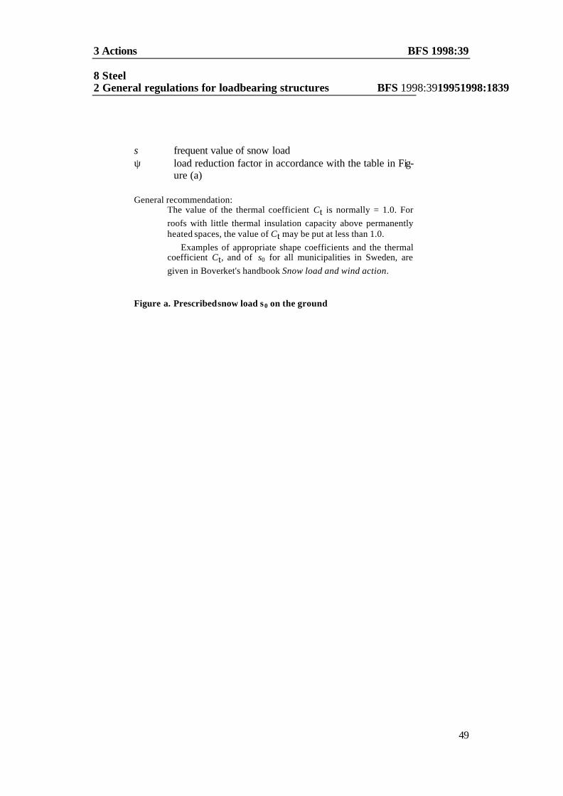
3 Actions BFS 1998:39 8 Steel 2 General regulations for loadbearing structures BFS 1998:3919951998:1839
49
s frequent value of snow load ψ load reduction factor in accordance with the table in Fig-
ure (a) General recommendation:
The value of the thermal coefficient Ct is normally = 1.0. For roofs with little thermal insulation capacity above permanently heated spaces, the value of Ct may be put at less than 1.0.
Examples of appropriate shape coefficients and the thermal coefficient Ct, and of s0 for all municipalities in Sweden, are given in Boverket's handbook Snow load and wind action.
Figure a. Prescribed snow load s0 on the ground

BFS 1998:39 8 Steel structures3 Actions
Basic value s0 of snow load
(kN/m2)
Load reduction factor ψ
> 3.0 0.8 2.5 0.7 2.0 0.7 1.5 0.7 1.0 0.6

3 Actions BFS 1998:39 8 Steel 2 General regulations for loadbearing structures BFS 1998:3919951998:1839
51
3:6 47 Wind action
3:61 This heading has been withdrawn by Statute (BFS 1998:39) Wind action shall be assumed to be a variable action and may be regarded as a fixed action within the framework of variations given for the different shape coefficients. Exceptions can be made for structures with large sideways dimensions and if the distribution of the action is of great signif icance to the load effect. (BFS 1998:39) General recommendation:
A third of the total wind load may in such cases be regarded as a movable action. (BFS 1998:39)
In calculating wind action it may be assumed that wind direc-
tion is horizontal but otherwise arbitrary. For objects with low damping ratio and stiffness, the dynamic
effects of the wind action shall be taken into account. (BFS 1998:39) The characteristic value Wk of wind action shall be determined
from formulae (a) and (b) below.
W q Ak k= µ (a)
q C C qk dyn exp ref= (b)
NOTATION
µ non-dimensional coefficient whose value depends on
wind direction and the shape of the elements of structure and objects acted upon by the wind
qk characteristic value of the dynamic wind pressure A area of the surface acted upon by wind Cdyn gust coefficient which is defined in Boverket’s handbook
Snow load and wind action. For structures with high damping ratio and stiffness, the value of Cdyn only de-pends on the height h of the building and the roughness parameter of the terrain z0. For structures with low dam-
47
Latest wording BFS 1995:18. The amendment means inter alia that the heading 3:61, Wind action on a structure of large inherent damping and rigidity, is deleted, that the general recommendations are deleted, a new first general recommendation is added, and that text from the earlier last general recommendation is moved to a new second general recommendation.

BFS 1998:39 8 Steel structures3 Actions
ping ratio and stiffness, the value of Cdyn also depends on the dynamic properties of the structure. (BFS 1998:39)

3 Actions BFS 1998:39 8 Steel 2 General regulations for loadbearing structures BFS 1998:3919951998:1839
53
Cexp exposure coefficient whose value depends on the height z above ground of the point on, or the area of, the building for which the wind action is to be determined, the terrain parameter β and the roughness parameter z0 of the terrain, as defined in Boverket's handbook Snow load and wind action
qref reference dynamic pressure due to the reference wind ve-
locity vref, i.e. 0.5 ρ ν2ref
The value of the reference wind velocity, as seen from Figure (a) overleaf, is based on a mean wind velocity during 10 minutes for terrain type II at a height of 10 m, with a return period of 50 years.
General recommendation:
Examples of suitable wind coefficients and methods for deter-mining the wind action are given in Boverket's handbook Snow load and wind action. (BFS 1998:39)
The characteristic value of the component of wind action paral-
lel to a surface may be determined from formula (a) if the shape coefficient µ is replaced by the coefficient µt.
The characteristic value of the total wind action acting upon elements of structure such as ceilings and partitions, and upon ob-jects such as unclad structural members and lattice masts, may be determined from formula (a) if the shape coefficient m is replaced by the coefficient µtot.
The frequent value of wind action shall be determined from formula (c) below.
W = ψ Wk (c)
with Wk according to formula (a) and the load reduction factor ψ = 0.25.
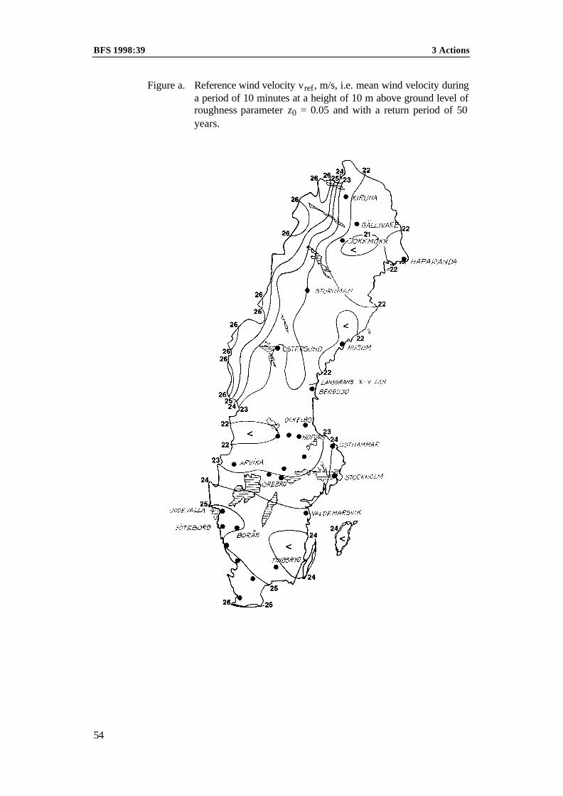
BFS 1998:39 3 Actions
54
Figure a. Reference wind velocity νref, m/s, i.e. mean wind velocity during a period of 10 minutes at a height of 10 m above ground level of roughness parameter z0 = 0.05 and with a return period of 50 years.
3 Actions BFS 1998:39
3:62 has been withdrawn by Statute (BFS 1998:39)
3:7 Pressure due to ice and water currents Consideration shall be given to pressure due to ice and water cur-rents.
General recommendation:
Ice pressure may be caused by changes in temperature in a station-ary sheet of ice, by the pressure of current on a stationary sheet of ice, or by ice in motion. The action due to ice pressure is depend-ent on local conditions, the design of the structure and the proper-ties of the ice. Changes in water level may give rise to vertical up-lift and to downward drag.
Ice pressure shall be assumed to act at the level of the water sur-
face. Ice pressure shall be assumed to be a free, variable static ac-tion which may in certain cases give rise to dy.
The action due to ice pressure need not be assumed to be di-vided into part actions.
3:8 Deformation action and accidental actions
Consideration shall be given to deformation action and accidental action. (BFS 1995:18)
General recommendation:
Appropriate methods for the determination of deformation action and accidental action are given in Boverket's handbook Vibra-tion, induced, deformation and accidental actions. (BFS 1995:18)


9 Aluminium structures BFS 1998:391999:464 Geostructures BFS 1998:391995:18
57
4 GEOSTRUCTURES
4:1 Requirements General recommendation:
General requirements are set out in Section 2:1.
Geostructures shall be designed so that – they do not give rise to changes in soil and groundwater condi-tions such that damage is caused to nearby buildings and other construction works, – they do not unduly obstruct the planned use of adjacent ground, and – they are not damaged by frost heave or movements caused by filling, excavation, groundwater lowering, erosion or vegetation. Geostructures shall be designed with regard to the interaction be-tween the structure and the subsoil.
General recommendation:
The redistribution of forces which may occur as a consequence of the rigidity of the structure and the stiffness of the subsoil should be taken into consideration.
4:2 Design assumptions General recommendation:
General design assumptions are given in Section 2:2.
4:21 Geotechnical categories (GK) Geostructures shall be designed, constructed and inspected in one of the geotechnical categories GK1, GK2 or GK3. GK1 shall not be applied for geostructures in Safety Class 3. Verification in ac-cordance with Section 2:3, for geostructures in GK3, shall have a scope and quality such that the standard at no time falls below that corresponding to GK2. There are no detailed rules for GK3. General recommendation:
GK1 and GK2 may be selected if the requirements of the manda-tory provision regarding geostructures in Safety Class 3 and the conditions set out in Table (a) overleaf are satisfied. If the condi-tions for GK2 are not satisfied, GK3 should be applied. Well documented local experience can also be taken into consideration in selecting the geotechnical category.

9 Aluminium structures BFS 1998:39BFS 1998:391995:18 4 Geostructures
58
Table a. Conditions for application of Geotechnical Category 1 (GK1) and Geo-technical Category 2 (GK2)
Factor Geotechnical
Category 1 (GK1) Geotechnical Category
2 (GK2)
Soil, rock and groundwater conditions
The subsoil should, if it is subjected to a load ex-ceeding 5 kPa, consist of soil or rock of low com-pressibility.
The pore water pressure is lower than that corre-sponding to a water table level with the bottom of the excavation, unless exten-sive local experience shows that necessary ex-cavation below groundw a-ter level can be carried out without risk.
The subsoil is such that the properties of the soil and rock can be deter-mined by well docu-mented and generally accepted methods.
The pore water pressure is lower than that corre-sponding to a water ta-ble situated not more than 1.0 m above the bottom of the excav a-tion, or out without risk.in the excavation.
Geostructure
Small, conventional and relatively simple geostruc-ture.
There is general practi-cal experience available regarding the geostruc-ture. Design and con-struction in accordance with generally accepted methods.
Conditions in the surroun-dings
There is no risk of collapse or slide.
Nearby structures and in-stallations are situated at such a distance that the geostructure does not af-fect their stability or de-formations.
Conditions in the sur-roundings are such that they do not substantially magnify the conse-quences of the failure of, or deformation in, the geostructure.
General recommendation:
Examples of geostructures for which GK1 can be applied: – Foundation structure for a building subject to normal re -quirements concerning limitation of the magnitude and uniform-ity of settlement. The design load in the ultimate limit state does not exceed 250 kN due to single columns or 100 kN/m due to a wall or several adjacent columns. The inclination to the vertical of the load resultant does not exceed 5°. The thickness of the layer of fill below the foundation structure is not greater than 1 m and it consists of compacted free draining friction soil. Piles are unspliced, precast, driven and mainly end bearing. – Retaining structures including basement walls for which the difference in the height of backfill on each side of the structure does not exceed 2 m, and where the backfill is not compacted with an implement heavier than a 100 kg vibrating plate. – Fill whose thickness is less than 3 m. – Excavations above groundwater level whose depth in silt or loose cohesive soil is less than 1.5 m and in firm soil less than 3 m.

9 Aluminium structures BFS 1998:391999:464 Geostructures BFS 1998:391995:18
59
Examples of geostructures for which GK2 can be applied: – Foundation structures for which the design vertical load in the ultimate limit state does not exceed 5 MN due to a single column or 1 MN/m due to a wall or several adjacent columns, and the mean value of the design vertical movement in the ser-viceability limit states is less than 0.05 m. – Geostructures which involve excavation not exceeding 1.5 m depth in silt, 3.0 m depth in clay and 5.0 m depth in friction soil. – Pile foundations constructed by well documented and gener-ally accepted methods.
4:2248 Geotechnical investigation A geotechnical investigation shall be carried out for all loadbearing geostructures. The investigation shall elucidate the geotechnical conditions relating to the design and construction of the geostruc-ture. The degree of detail of the investigation shall be chosen in view of the geotechnical category of the structure.
Available information concerning soil, rock and groundwater conditions and information concerning the foundations of affected buildings shall be compiled.
Further geotechnical investigations for geostructures in GK 1 are not necessary if the following requirements are satisfied: – Available information provides the basis for a reliable assess-ment of ground and groundwater conditions in the area. – An inspection of the area concerned confirms that there is no likelihood of the occurrence of any loose and compressible soil strata. The inspection shall be carried out by a geotechnician. (BFS 1998:39)
Geotechnical field and laboratory investigations shall, in GK2 and GK3, have a scope such that information is obtained of soil, rock and groundwater conditions in those respects which are sig-nificant for the safety, function and environmental effect of the geostructure.
General recommendation:
Apart from sufficient information for the safe and economic de-sign, construction and inspection of loadbearing structures, the geotechnical investigations should provide the information nec-essary for the design of drainage, frost insulation and action to prevent hygienic inconvenience due to radon gas or other sub-stances which may emanate from the ground.
The information should be interpreted and compiled, so that the documentation on which design is based contains the follow-ing information: – topography of the ground surface – sequence of soil strata (materials, boundaries between strata), – groundwater conditions, – the material properties of soil and rock, – the design, position and condition of adjacent structures.
48
Latest wording BFS 1995:18.

9 Aluminium structures BFS 1998:39BFS 1998:391995:18 4 Geostructures
60
The results of the geotechnical field and laboratory investiga-tions should be documented in a separate report which contains no interpretations, calculations or recommendations.The docu-mentation should be in the form of plans and sections and tables and diagrams, using the notation laid down by the Swedish Ge o-technical Association. Information should be given concerning methods nd equipment used, time of year, weather, the person in charge of the investigation, the project, client etc which may be useful in interpreting the results.
In GK3, the geotechnical survey shall also comprise the in-
vestigations necessary in view of the special conditions which have resulted in the geostructure being assigned to GK3.
4:23 Characteristic values The characteristic value of a material property shall normally be determined as its mean value. Systematic differences between the property during the investigation and in the real structure (design situation), the temporal variation of the property and errors in de-termining parameters, shall be taken into consideration.
The characteristic value and its dependence on depth shall be determined for each individual stratum in a soil profile. The se-quence of strata in the vertical direction and the horizontal extent of the soil stratum shall be selected so that each stratum has a ho-mogeneous composition and the same geological history.
The characteristic value of a material property may also be de-termined by careful choice on the basis of documented experience. This shall be systematised and formulated as a rela tionship be-tween the sought property and, for instance, the results of a sound-ing or the value of a consistency parameter or similar.
4:24 Tolerances For geostructures, tolerances shall be specified for dimensions which are of essential significance for the function of the structure.
General recommendation:
Examples of dimensions for which tolerances should be speci-fied: – the level of the surface of a fill and the level of the bottom of an excavation, – the inclination of excavation slopes, – the position and rake of piles, – distance from a nearby building, other construction works or some other load.
4:25 Durability The changes in the properties of the soil and rock material which may be expected to occur during the service life of the geostructure shall be taken into consideration in selecting the design assump-tions and material parameters.

9 Aluminium structures BFS 1998:391999:464 Geostructures BFS 1998:391995:18
61
4 :3 Design by calculation and testing (BFS 1995:18) General recommendation:
General provisions concerning design are set out in Section 2:3. (BFS 1995:18)
4:31 Design in the ultimate limit states In the case of geostructures, special consideration shall be given, in addition to the conditions in Section 2, to an ultimate limit state which is characterised by the fact that movements of the geo-structure cause material failure or loss of support for part of the supported loadbearing structure or an adjacent structure even if the bearing resistance of the soil is not exceeded.
General recommendation:
A method for calculating deformations should take account of a possibly nonlinear relationship between load and deformation.
Design in the ultimate limit states, in cases where the provisions of Subsections 4:31, 4:32 and 4:33 are not applicable, shall be carried out in accordance with the principles in Sections 2:3 and 4:2. (BFS 1995:18)
The value of the partial factor γm shall be selected on the basis of the conditions set out in Table (a) below
Table a. Conditions to be taken into consideration in selecting the
value of the partial factor γm in the ultimate limit states.
Favourable conditions Unfavourable conditions
Experience shows that the ma-terial property has little scatter.
Experience shows that the material property has large scatter.
Test results from the geotechni-cal investigation show that scat-ter is normal.
Test results from the geotechnical inves-tigation show that scatter is greater than normal.
The investigations are of large scale and permit good deter-mination of the material prop-erty.
The investigations are of small scale.
The investigations are carried out by well documented meth-ods which give reproducible re-sults.
The investigations are carried out by methods which have poor reproducibility or by methods based on limited experi-ence.
Additional checks on the mate-rial property.
No additional checks on the material property.
Little uncertainty in converting test results into the sought re-sults material property.
Great uncertainty in converting test re-sults into the sought material property.
Failure is ductile. Failure is brittle.
(BFS 1995:18)

9 Aluminium structures BFS 1998:39BFS 1998:391995:18 4 Geostructures
62
General recommendations: In designing geostructures, γm should take account of the uncer-tainty in the determined value of the material property, and γRd of the uncertainty in the analytical model and the design assump-tions.
The value of γm should be chosen on the basis of table (b) be-low and in such a way that the lower limiting value is taken only if conditions are in all respects favourable, and the upper limiting value if unfavourable conditions predominate. In other cases a reasonable intermediate value of γm is to be chosen. If conditions are unfavourable in many respects, the geotechnical investiga-tions should be extended.
Table b. Partial factor γm in the ulti-mate limit states.
Material property Partial factor γm
Modulus and other deformation parameters
Strength parameter tan ϕ
Other strength parameters
1.2 – 1.8
1.1 – 1.3
1.6 – 2.0
If the mode of action or extent of the geostructure is such that
the bearing resistance is not determined by a local value of the material property, the value of γm can be reduced. The value of γm can be reduced by 20% in cases where the bearing resistance of the geostructure is determined by the mean value of the mate-rial property. If the bearing resistance is to some extent deter-mined by a local value of the material property, a reasonable re-duction between 0 and 20% can be made. However, in determin-ing the value of-tan ϕd a value lower than γm = 1.05 should not be used. For other material properties the value of the partial fac-tor γm should not be lower than 1.0.
In designing for accidental actions, the value of the partial factor γm can be reduced by 10%. A value lower than γm = 1.0 should not however be used.
When a high value of a material property is unfavourable for the geostructure, e.g. in determining the action effect of an im-posed deformation, the design value should be selected so that it is not less than the 95% fractile of the property.
:311 Earth pressure :3111 Geotechnical category 1 (GK 1)
General recommendation: General provisions concerning earth pressure are set out in Sec-tion 3:2.
Earth pressure due to uncompacted backfill shall for drained and flexible structures be calculated according to formula (a) below.
pd = kd(γdz+qd) (a)

9 Aluminium structures BFS 1998:391999:464 Geostructures BFS 1998:391995:18
63
NOTATION
pd design intensity of earth pressure at depth z below the ground surface
kd design earth pressure coefficient for backfill. The value of kd shall be taken to be
0.35 for sand and gravel 0.5 for silt 0.6 for clay
γd unit weight of backfill (design value)
z depth below ground surface
qd external uniformly distributed design load on the ground surface (see Section 3:2), situated at a distance from the structure less than 1.5 × the foundation depth.
For rigid structures earth pressure shall be assumed to be 50% higher.
Earth pressure due to compaction shall be given special consid-eration as appropriate.
General recommendation:
The structure should be designed so that earth pressure does not increase in winter as a result of frost action.
:312 Foundation slabs :3121
49
Geotechnical Category 1 (GK1) The requirements in both the ultimate and serviceability limit states shall be considered to have been satisfied for foundation slabs in GK1 if – the action resultant does not deviate more than 5° from the ver-tical, – the width and foundation depth of the foundation slab are each not less than 0.4 m, and – condition (a) below is satisfied.
The requirement concerning foundation depth does not however apply on rock.
Svd < Rvd (a)
49
Latest wording BFS 1995:18. The amendment means that the general recommendation is deleted.

9 Aluminium structures BFS 1998:39BFS 1998:391995:18 4 Geostructures
64
NOTATION Svd vertical design load in the ultimate limit states including
self weight and backfill if any on the structure Rvd design vertical bearing resistance, fd Aef fd design foundation pressure according to Table (a) below Aef effective foundation area bef × lef according to Figure a.
Figure a. Figure for calculation of effective foundation area
Table a. Design values of foundation pressure for slabs in Geo-
technical Category 1 (GK 1)
Material fd (kPa) Material fd (kPa)
Rock (unweathered) 400 Sand 100
Till 200 Silt 50
Gravel 150 Firm clay1 100
1 Characteristic shear strength > 50 kPa under undrained conditions
For sand and silt the value of fd shall be limited to one half the
tabulated value if the groundwater level is higher than one slab width below the foundation level.
If different soil strata occur within a depth of twice the slab width measured from the foundation level, the design value of foundation pressure shall be determined on the basis of the worst material in question.
Action resultant

4 Geostructures BFS 1998:39
65
:3122 Geotechnical Category 2 (GK2) and Geotechnical Category 3 (GK3) The bearing resistance of foundation slabs shall satisfy condition (a) below.
Sd < Rd (a)
NOTATION Sd design action effect in the ultimate limit states Rd design bearing resistance in the ultimate limit states
General recommendation:
General provisions regarding tilting, uplift and sliding are given in Subsection 2:112.
:313 Piles :3131 Geotechnical Category 1 (GK1)
A foundation structure in GK1 shall be designed so that the load resul-tant does not deviate by more than 5° from the vertical. The require-ments in the ultimate and serviceability limit states shall in GK1 be considered to have been complied with for precast unspliced piles which – are designed in accordance with Swedish Standard SS 81 11 03, – have a design load effect < 300 kN per pile, – trasmit most of the load to rock or loadbearing soil stratum at the pile point, and – are driven to refusal in accordance with the following rules. Driving to refusal shall be carried out with a free fall hammer or a sin-gle line drop hammer. The drop for a free fall hammer shall be 0.3 m and for a single line drop hammer 0.4 m. The hammer shall weigh not less than 3 tonnes.
Driving to refusal shall comprise not less than three series of ten blows, during which the set shall be constant or decreasing, and not more than 10 mm per 10 blows. Before piling is terminated, redriving shall be carried out.
General recommendation:
Redriving should comprise not less than 25% of the number of piles. If the set during redriving exceeds the value specified above, all piles should be redriven.

BFS 1998:39 4 Geostructures
66
If the pile point reaches rock or supposed rock, the pile shall be embedded in this before driving to refusal is carried out. After em-bedment in the rock, driving to refusal may be carried out by one se-ries of 10 blows if the set due to this does not exceed 3 mm.
:3132 Geotechnical Category 2 (GK 2) and Geotechnical Category (GK3)The bearing capacity of all the parts of the precast pile shall be deter-mined in accordance with the design regulations for the material con-cerned. Verification of the bearing resistance of piles with regard to failure of the surrounding soil or rock shall be carried out either by calculation or by testing, due consideration being given to the prevail-ing soil and driving conditions.
General recommendation:
For piles which are substantially end bearing piles, bearing resi-stance can be verified by driving to refusal.
The maximum value of the permanent set during driving to re-fusal should be selected within the range 10 – 30 mm per 10 blows.
In GK2 the conditions governing driving to refusal can be deter-mined on the basis of well documented and systematised experience.
If the conditions governing driving to refusal are determined by test piling and dynamic load tests in accordance with Subsection 4:33, the test should comprise not less than 5% of the number of piles, but not less than four, distributed over the area.
In cases where piling warrants construction in GK3, the conditions
governing driving to refusal shall be determined with regard to the structure in question if bearing resistance is verified in this way.
4:32 Design in the serviceability limit states It shall be borne in mind that for geostructures the serviceability limit states often constitute the design criterion.
General recommendation:
In designing geostructures in the serviceability limit states, the inter-action between soil (rock) and the other parts of the structure should be taken into consideration. Limiting values C, for instance for de-formations, should be laid down so that, in addition to the require-ments in Subsection 2:12, the requirements of the client regarding limitation of maintenance and service costs are also taken into con-sideration.
In calculating deformations, it should be borne in mind that the load-deformation curve for geostructures is often nonlinear.
For calculating deformations due to actions of long duration, the actions can be determined in accordance with Subsection 2:21. Ap-propriate values of ψ1 are set out in BBK 94, Subclause 2.2.2.

4 Geostructures BFS 1998:39
67
The design criterion for settlement in the serviceability limit states can be put at
Sd < Sacc (a) ∆Sd < ∆Sacc (b) NOTATION Sacc acceptable total settlement ∆Sacc acceptable differential settlement Design values of the settlement sd or the differential settlement ∆Sd can be determined in different ways: – The settlements are calculated with the design values of the pa-
rameters according to Subsections 2:322 and 4:31. The uncer-tainty in the analytical model and the design assumptions is to be taken into consideration by γRd. The partial factor γn is put equal to 1.0, and the value of γm is put at 90% of the corresponding fac-tor in the ultimate limit states, but not less than 1.0.
– The settlements are calculated with the characteristic values of the parameters according to Subsection 4:23 after which the total settlement or differential settlement is corrected with respect to the uncertainty in the calculated value either by adding an incre-ment or multiplying it by a factor based on compiled and evalu-ated experience data.
4:33 Design by testing (BFS 1995:18) The bearing resistance and deformations of geostructures may be de-termined on the basis of the results of tests. In such a case, primary consideration shall be given to the following factors: – Deviations in soil and groundwater conditions between the test site and the site of the planned geostructure. – Temporal effects. – Scale effects. – Differences in the mode of action during the test and during design.
General recommendation:
Characteristic values of bearing resistance and deformation pro-perties can, if a sufficient number of tests are made, be determined in accordance with Subsection 2:33 and Boverket's handbook De-sign by testing. See Subsection 4:23.
If a small number of load tests are carried out, the distribution of
test results shall be used only to check that an empirical design proce-dure is appropriate for the planned design of the geostructure in the prevailing soil and groundwater conditions. The structure shall in the ultimate and serviceability limit states be designed in accordance with Subsections 4:31 and 4:32.

BFS 1998:39 4 Geostructures
68
4:4 Materials General recommendation:
General provisions regarding materials are given in Section 2:4.
4:5 50 Execution and workmanship General recommendation:
General provisions regarding execution and workmanship are given in Section 2:5.
For the construction of geostructures in GK2 and GK3, an execution procedure sheet shall be drawn up in consultation with the designer of the geostructure. (BFS 1998:39)
General recommendation: The execution procedure sheet should set out the working procedure and the sequence of operations, and restrictions with respect to e.g. harmful deformations. The execution procedure sheet should be re-lated to the design and to the inspection. (BFS 1998:39)
During construction a diary shall be kept to document the work carried out, precipitation, temperature and any other observations which may be useful in evaluating the structure.
4:6 51 Supervision and control The values of the partial factor γm set out in this section presuppose that the supervision and control referred to in Section 2:6 is carried out.
General recommendation: Basic inspection of geostructures should in all geotechnical catego-ries comprise a check that the real soil, rock and groundwater condi-tions agree with the assumptions on which design has been based.
Additional inspection of geostructures in GK2 should comprise checks, formulated with respect to the structure in question, regard-ing the bearing resistance, function and durability of the structure and its effect on the surroundings.
Additional inspection of geostructures in GK3 should be carried out in accordance with the rules for GK2, subject to the following additional measures. Checks by the design team shall be supple-mented by inspection carried out by an independent expert uncon-nected with the project in question. (BFS 1998:39)
50
Latest wording BFS 1995:18. 51
Latest wording BFS 1995:18.

5 Timber structures BFS 1998:391995:18
69
5 TIMBER STRUCTURES
5:1 Requirements General recommendation:
General requirements are set out in Section 2:1.
5:11 Durability Timber structures shall be designed and constructed so that harmful attack by rot and wood destroying insects is prevented. Structural connectors of steel shall be protected against harmful corrosion, and glued joints shall have satisfactory durability.
5:2 Design assumptions General recommendation:
General design assumptions are set out in Section 2:2.
5:21 Service classes In designing timber structures, consideration shall be given to the ef-fect of moisture on resistance and stiffness. This shall be done by as-signing the elements of structure to one of the following service classes and using the appropriate factors in determining the design values.
Service Class 0 is characterised by an environment in which relative humidity exceeds 65% for only a few weeks each year and, on aver-age, does not exceed 40%.
Service Class 1 is characterised by an environment in which relative humidity exceeds 65% for only a few weeks each year and at no time reaches 80%.
Service Class 2 is characterised by an environment in which relative humidity exceeds 80% for only a few weeks each year.
Service Class 3 is characterised by an environment which produces in the materials a higher moisture content than that corresponding to Service class 2.
5:22 The duration of actions The effect of the duration of actions on resistance and stiffness shall be taken into consideration in designing timber structures. This shall be done by means of modification factors κr and κs in

BFS 1998:39 5 Timbers structures
70

5 Timber structures BFS 1998:391995:18
71
accordance with Subsections 5:3121 and 5:322. These factors shall be determined with respect to the load duration classes set out in Table (a) below.
Table a. Classification of actions in view of their duration
Load duration Class
Cumulative dura-tion of action
Example of action1
Permanent load
Load type P more than10 years
Self weight of permanent parts of the building.
Variable load
Load type A between 6 months and 10 years
The fixed portion of the imposed. load. Snow load of frequent v alue.
Load type B between 1 week and 6 months
The free portion of the imposed load. Wind action of frequent value. Snow load of characteristic value.
Actions on concrete formwork and similar temporary structures.
Load type C less than 1 week Wind action of characteristic value. Single concentrated load on a roof.
1 The above examples are intended only as general recommendations.
5:23 Characteristic values for wood based materials Unless it can be shown that other values are more appropriate, the characteristic values set out in Tables (a) – (d) below may be used in calculating the resistance and stiffness of structural timber, glued laminated timber and wood based structural grade boards (K plywood, K board, K particleboard and flooring grade particleboard). (BFS 1998:39)
General recommendation: The tabulated characteristic values should in some cases be adjusted to take account of size effects.
In tension perpendicular to the grain the effect of size may be taken into account according to Subsection 5:3122.
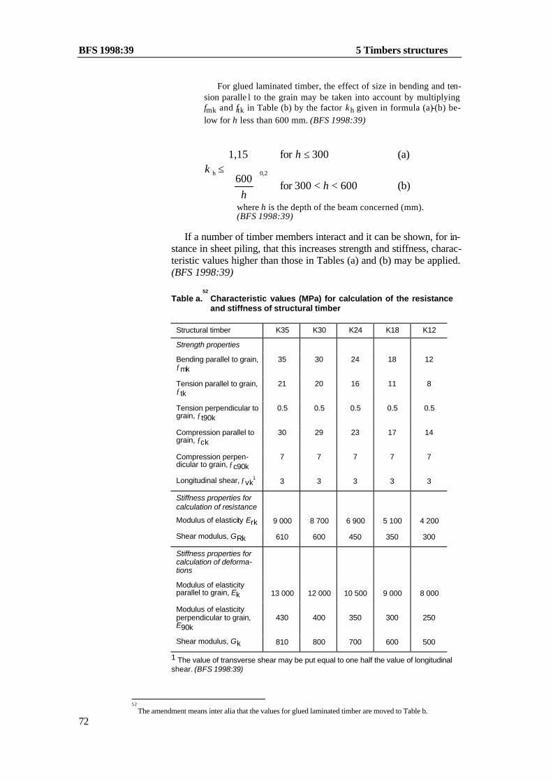
BFS 1998:39 5 Timbers structures
72
For glued laminated timber, the effect of size in bending and ten-sion paralle l to the grain may be taken into account by multiplying fmk and ftk in Table (b) by the factor κh given in formula (a)-(b) be-low for h less than 600 mm. (BFS 1998:39)
<<
≤≤
b)(600300for 600
(a)300for 1,15
0,2h
hh
hκ
where h is the depth of the beam concerned (mm). (BFS 1998:39)
If a number of timber members interact and it can be shown, for in-
stance in sheet piling, that this increases strength and stiffness, charac-teristic values higher than those in Tables (a) and (b) may be applied. (BFS 1998:39)
Table a.52
Characteristic values (MPa) for calculation of the resistance and stiffness of structural timber
Structural timber K35 K30 K24 K18 K12
Strength properties
Bending parallel to grain, ƒmk
35 30 24 18 12
Tension parallel to grain, ƒtk
21 20 16 11 8
Tension perpendicular to grain, ƒt90k
0.5 0.5 0.5 0.5 0.5
Compression parallel to grain, ƒck
30 29 23 17 14
Compression perpen-dicular to grain, ƒc90k
7 7 7 7 7
Longitudinal shear, ƒvk1 3 3 3 3 3
Stiffness properties for calculation of resistance
Modulus of elasticity Erk 9 000 8 700 6 900 5 100 4 200
Shear modulus, GRk 610 600 450 350 300
Stiffness properties for calculation of deforma-tions
Modulus of elasticity parallel to grain, Ek
13 000
12 000
10 500
9 000
8 000
Modulus of elasticity perpendicular to grain, E90k
430
400
350
300
250
Shear modulus, Gk 810 800 700 600 500
1 The value of transverse shear may be put equal to one half the value of longitudinal shear. (BFS 1998:39)
52
The amendment means inter alia that the values for glued laminated timber are moved to Table b.

5 Timber structures BFS 1998:391995:18
73
Table b. Characteristic values (MPa) for calculation of the resistance and stiffness of glued laminated timber and glued structural timber
Glued laminated timber1
Glued structural timber
L40 L30
LK30
LK20
Strength properties
Bending parallel to grain, ƒmk 333 263 30 24
Tension parallel to grain, ƒtk 23 17 20 16
Tension perpendicular to grain, ƒt90k
0.5 0.5 0.5 0.5
Compression parallel to grain, ƒck
36 29 29 23
Compression perpendicular to grain, ƒc90k
8 7 7 7
Longitudinal shear, ƒvk2 44 3 3 3
Stiffness properties for calcul a-tion of resistance
Modulus of elasticity ERk 10 400 8 700 8 700 6 900
Shear modulus, GRk 700 600 600 450
Stiffness properties for calcul a-tion of deformations
Modulus of elasticity parallel to grain, Ek
13 000
12 000
12 000
10 500
Modulus of elasticity perpen-dicular to grain, E90k
450
400
400
350
Shear modulus, Gk 850 800 800 700
(BFS 1998:39) 1 The tabulated characteristic values for glued laminated timber refer to beam cross sections ≥ 600 mm depth. 2 The value of transverse shear may be put equal to one half the value of longitudinal shear. 3 In bending with the moment vector perpendicular to the plane of the glue joint, the value of ƒmk may however be put at not more than 26 MPa for L40 and not more than 21 MPa for L30. 4 The tabulated value refers to beams of rectangular section. For beams of non-rectangular section, ƒvk = 3 MPa. (BFS 1998:39)

BFS 1998:39 5 Timbers structures
74
Table c. Characteristic values (MPa) for calculation of the resistance and stiffness of K−plywood (structural grade plywood). (BFS 1998:39)
Strength Class
K- plywood P40 P30 P20
Strength properties
Bending about an axis in the plane of the board, ƒmk
1 40 30 20
Tension parallel to the plane of the board, ƒtk1 35 25 20
Tension perpendicular to the plane of the board, ƒt90k
0.5 0.5 0.5
Compression parallel to the plane of the board, ƒck
1 30 25 20
Compression perpendicular to the plane of the board ƒc90k
7 7 7
Panel shear, ƒpk2 3 3 3
Rolling shear, ƒv k3 1 1 1
Stiffness properties for calculation of resistance
Modulus of elasticity parallel to the board, ERk1 8 700 8 700 6 900
Shear modulus in panel shear, GRk2 450 450 350
Stiffness properties for calculation of deforma-tions
Modulus of elasticity parallel to the board, Ek1 12 000 12 000 10 500
Shear modulus in panel shear, Gk2 600 600 500
1 Only plies with the direction of the grain parallel to the direction of stress shall be considered. The values presuppose that not less than two plies are effective. If only one ply is effective, the values shall be reduced by half. 2 All plies may be considered. The tabulated values refer to shear stresses parallel to a grain. When stress is at an angle of 45° to the grain, the values may be doubled. 3 All plies may be considered.

5 Timber structures BFS 1998:391995:18
75
Table d. Characteristic values (MPa) for calculation of the resis-tance and stiffness of K board, K particleboard and flooring grade particleboard. (BFS 1998:39)
K board
Strength Class
K particleboard Flooring grade Particleboard (t > 19 mm)
Thickness t (mm) K50 K40 K35 K13 <14 14-19 >19
Strength properties
Bending about an axis in the plane of the board, fmk
44
38
31
13.5
20
18
16
Tension parallel to the plane of the board, ftk
25
22
20
6
10
9
8
Tension perpendicular to the plane of the board, ƒt90k
0.85
0.85
0.65
0.1
0.6
0.5
0.4
Compression parallel to the plane of the board, fck
25
22
20
6
12
12
10
Compression perpen-dicular to the plane of the board, fc90k
25
24
22
4
7
7
7
Panel shear, fpk 15 14 12 3.5 7 6 5
Rolling shear, fv k 2.4 2.4 1.5 0.2 2 1.6 1.3
Stiffness properties for calculation of resis-tance
Modulus of elasticity, bending, Erk
4 000
4 000
3 500
2 000
2 000
1 800
1 800
Tension and com-pression, EtRk, EcRk
4 000
4 000
3 500
2 000
1 800
1 500
1 500
Shear modulus, GRk 1 700 1 700 1 500 800 900 700 700
Stiffness properties for calculation of deforma-tions
Modulus of elasticity, bending Ek
6 700
5 000
4 500
3 000
4 000
3 500
3 000
Tension and com-pression, Etk, Eck
6 700
5 000
4 500
3 000
2 600
2 400
2 200
Shear modulus, Gk 3 350 2 100 1 900 1 300 1 300 1 200 1 100

BFS 1998:39 5 Timbers structures
76
5:24 Characteristic loadcarrying capacity of timber joints The characteristic values of the loadcarrying capacity of timber joints shall be determined with regard to those properties of the timber and the fasteners which are significant for their loadcarrying capacity and durability.
General recommendation:
Determination of characteristic values on the basis of test results should be made in accordance with Boverket's handbook Design by testing.
:241 Nailed joints subject to shear force
Figure a. Pointside penetration lengths for nails
l1 l2 l2 l2l3
General recommendation: If the conditions in Section 5:4 are satisfied, the characteristic value of the loadcarrying capacity Rvk (N) of a nail per shear plane can be determined from formulae (a) – (b) below.
Rvk = 150 d1.7 for a square or grooved wire nail (a) Rvk = 125 d1.7 for a round nail (b)
where d is the least side dimension (mm) of the nail. The value of Rvk according to the formulae is valid on condition that —– the nails are driven perpendicular to the grain, —– the thickness of the thinnest piece of timber is at least 7d, —– the pointside penetration lengths of nails inclusive of the points as shown in figure (a) are l1 > 8d from both sides for nails in double shear l2 > 12d for smooth nails in accordance with formula (a) or (b) (BFS 1998:39)

5 Timber structures BFS 1998:391995:18
77
l2 > 8d for annular ringed shank nails and helically threaded nails,

BFS 1998:39 5 Timbers structures
78
—– the spacing of nails along the grain and the distance be-tween a nail and an unloaded end of a timber is not less than 10d, and the distance between a nail and a loaded end of a timber is not less than 15d,

5 Timber structures BFS 1998:391995:18
79
—– the spacing of nails perpendicular to the grain and the distance between a nail and an unloaded edge of a timber is not less than 5d, and the distance between a nail and a loaded edge of a tim-ber is not less than 10d, and —– the joint contains not less than 2 nails.
Definitions of unloaded and loaded edge of the timber, and unloaded and loaded end respectively, are given in Figure 6.3.1.2a of SS-ENV 1995-1-1. (BFS 1998:39)
For thinner pieces of timber or shorter pointside penetration lengths the value of Rvk is to be reduced for the shear plane con-cerned in proportion to the thickness of the thinnest piece of timber or the shortest pointside penetration length. The thickness of timber and the pointside penetration length l1 shall not however be less than 5d. The pointside penetration length l2 shall not be less than 8d for smooth nails nor less than 5d for annular ringed shank nails and helically threaded nails. In addition, for joints in single shear, l2 shall be not less than half the length of the nail. If the dimension l3 ac-cording to Figure (a) is greater than 3d, the nails from the side pieces may touch each other in the middle piece.
A higher characteristic value of the load-carrying capacity of a nail may in some cases be applied for nailed steel to timber joints, see for example SS-ENV 1995-1-1, 6.3.1.4, and its associated NAD(S). (BFS 1998:39)

BFS 1998:39 5 Timbers structures
80
:242 Nailed joints subject to withdrawal force Figure a. Nail subject to withdrawal force
Ft2
Ft
2
l
t
Ft
d
hd
General recommendation:
If the conditions in Section 5:4 are satisfied, the characteristic value of the loadcarrying capacity of nails anchored in timber, subject to a withdrawal force, can be determined as the least value of Rtk accord-ing to formulae (a) – (c) below.
R
d l f
d t f d 2 f
d2 ftk
tk (a)
tk hk only smooth nails (b)
hk only annular ringed shank nails (c) and helically threaded nails
≤ +
The value of Rtk holds both when nails are driven perpendicular
to the grain and when they are driven symmetrically on the skew (slant nailing), provided that —– the pointside penetration length l is not less than 12d for smooth nails and not less than 8d for annular ringed shank nails and helically threaded nails, —– the nails are driven at an angle of 45° or greater to the grain, —– the nails are not driven into the end grain.
The strength parameters ftk and fhk are to be taken from Table (a) below. For annular ringed shank nails the pointside penetration length l refers only to the annular portion of the nail.
Table a. Strength parameters ftk and fhk (MPa) for nails subject to a withdrawal force
ftk fhk1
Square and grooved nail 0.9 50
Round nail 0.7 50
Annular ringed shank nail, helically threaded nail
3 50
Hot dip zinc coated annular ringed shank nail 2 50

5 Timber structures BFS 1998:391995:18
81
1 The values presuppose that dh > 2.5d

BFS 1998:39 5 Timbers structures
82
:24353 Bolted joints subject to shear force General recommendation:
For a bolt subject to shear force, the characteristic value of the loadcarrying capacity per shear plane can be determined as the least value of Rvk (N) according to formulae (a) – (e) below.
R
t t dt dt d
t d d
df
vk
yk
only joint in single shear (a)only joint in double shear (b)
(c)(d)
(e)
≤
+
+
+
612244 22
30240
1 1 2 2
2 2
1 1
1 12
21 2
( )κ κκκ
κ
κ κ
NOTATION t thickness of a timber member (mm) d diameter of bolt (mm) fyk yield stress of bolt material (Mpa)
κ factor which takes account of the angle α between the direction of force and the direction of grain and which can be determined according to Figure (a) or formulae (g) – (h) below.
α angle between the direction of force and the direction of grain
In a joint in double shear, the subscript 1 denotes the outside member and the subscript 2 the middle member. For a joint in single shear, the subscripts are to be chosen so that κ1t1 < κ2t2 (f)
The value of Rvk presupposes that the spacing of bolts along the grain and the distance between a bolt and the end of a timber member is not less than 7d, and the spacing of bolts perpendicu-lar to the grain and the distance between a bolt and a loaded edge of a timber member is not less than 4d. The minimum distance between a bolt and an unloaded timber edge may however be 2d.
Higher values can normally be applied for nailed steel to tim-ber joints.
53
The amendment means inter alia that the last paragraph in the general recommendation before Table a is deleted.

5 Timber structures BFS 1998:391995:18
83
Figure a. Factor κ in a bolted joint
= 6 mm
= 12 mm= 20 mm
= 24 mm
° ° ° ° ° ° ° ° ° °0 10 20 30 40 50 60 70 80 90
0
0.2
0.4
0.6
0.8
1.0
α
d
dd
d
κ
κκ
κ α α=
+
90
902 2cos sin (g)
κ 90 0 8 1 5= + −.45 .d (h)
A higher characteristic value of the load-carrying capacity of a bolt may in some cases be applied for bolted steel to timber joints, see for example SS-ENV 1995-1-1, 6.5.1.4, and its asso-ciated NAD(S). (BFS 1998:39)
:24454 Screwed joints subject to shear force General recommendation:
For a wood screw inserted perpendicular to the grain, the charac-teristic value of the loadcarrying capacity per shear plane, under the action of shear force, can be determined as the least value of Rvk (N) according to formulae (a) – (c) below.
R
t d
t d d
df
vk
yk
(a)
(b)
(c)
≤ +
+
24
4 22
26180
1
12
21 2
κ
κ
κ κ
NOTATION t headside timber thickness (mm) d shank diameter of the screw (mm) κ factor which takes account of the angle α between the di-
rection of force and the direction of grain according to Subsection 5:243
fyk yield stress of the material of the screw (MPa)
54
Latest wording BFS 1995:18.
BFS 1998:39 5 Timbers structures
84
The value of Rvk presupposes that the joint comprises not less than two screws and that the provisions of Subsection 5:243 regarding spacing and distances are applied. It is further presup-posed that the thickness of the timber member is not less than 2d and that the pointside penetration length of the screw is not less than 8d. If the pointside penetration length is less than 8d, the value of Rvk is to be reduced in proportion to the length. The pointside penetration length shall not however be less than 5d.
A higher characteristic value of the load-carrying capacity of a wood screw may in some cases be applied for screwed steel to timber joints. (BFS 1998:39)
:245 Screwed joints subject to withdrawal force General recommendation:
For a screw inserted perpendicular to the grain, acted upon by a withdrawal force, the characteristic value of the loadcarrying ca-pacity, Rtk (N), can be determined from formula (a) below.
R d l dtk g= + −11 2 5( . ) ( ) (a)
NOTATION d shank diameter of screw (mm) lg threaded pointside penetration length (mm)
:246 Glued joints The characteristic value of the shear strength in a glued joint shall be not greater than the lowest characteristic value of the shear strength for the materials comprised in the joint. In types of glued joints other than those between unspliced laminates and between unspliced flanges and webs in beams, the risk of nonuniform stress distribution shall be taken into consideration.
5:3 Design by calculation and testing (BFS 1995:18) General recommendation:
General provisions concerning design are set out in Section 2:3. (BFS 1995:18)

5 Timber structures BFS 1998:391995:18
85
5:31 Design in the ultimate limit states
:311 Calculation of forces and moments General recommendation:
In calculating forces and moments in timber structures, a linear relationship between stress and strain may be assumed for the wood material.
Displacements in mechanical joints shall be taken into conside-ration.
Where several connectors interact in a joint, distribution of for-ces in the joint shall be determined with regard to the deformation of the timber members and the stiffness and deformation capacity of the connectors. General recommendation:
The load-carrying capacity for laterally loaded bolts in line with the load direction may be determined in accordance with NAD(S) to SS-ENV 1995-1-1, 6.5.1.1. (BFS 1998:39)
Movements in timber structures caused by moisture shall be
taken into consideration if they have significance for the resi-sstance.
In determining section properties, the effect due to reduction of the cross section shall be taken into consideration. Holes due to bolts, screws and nails need not however be taken into considera-tion if the lateral dimensions of the connectors are not greater than 6 mm.
In calculating shear forces in a beam supported at its bottom edge and loaded at the top, such load may be ignored if the dis-tance between the load and the theoretical point of support is less than the depth of the beam.
:312 Calculation of resistance The resistance of a timber structure shall be determined in accor-dance with the elastic theory unless some other procedure can be shown to be more correct. It shall however be borne in mind that the resistance of timber and wood based material may be limited by compressive strain.
In joints subject to tension perpendicular to the grain, the risk of splitting shall be taken into consideration. (BFS 1995:18)

BFS 1998:39 5 Timbers structures
86
:312155
Design values of material propertiesThe design values of strength, resistance, modulus of elasticity and shear modulus in the ultimate limit states shall be determined from formulae (a) – (d) below.
ff
dr k
m n
=κ
γ γ (a)
RR
dr k
m n
=κ
γ γ (b)
EE
Rdr Rk
m n
=κ
γ γ (c)
GG
Rdr Rk
m n
=κ
γ γ (d)
NOTATION fk, Rk characteristic value of strength and resistance respec-
tively in accordance with Subsections 5:23 and 5:24 ERk characteristic value of modulus of elasticity for cal-
culation of resistance in accordance with Subsection 5:23 GRk characteristic value of shear modulus for calculation of
resistance in accordance with Subsection 5:23 γm partial factor for resistance γn partial factor for safety class in accordance with Subsec-
tion 2:115 κr modification factor which takes account of the effect of
moisture and load duration in accordance with Subsec-tions 5:21 and 5:22. Values of κr are set out in Tables (a) – (e) below.
In the ultimate limit states the value of the partial factor γm shall be put equal to 1.25. In type approved structures and structures subject to factory production control, where design and production are carried out in such a way that a smaller scatter in strength prop-erties may be expected, the value of γm in the ult imate limit state may however be put equal to 1.15.
55
Latest wording BFS 1995:18.

5 Timber structures BFS 1998:391995:18
87
Table a. Modification factor κ r for calculation of the resistance of structural timber and glued laminated timber in Service Classes 0, 1 and 21.
Action of shortest duration in a combination of actions2
Strength classes P or A B C
fm, ft, fc, ER, GR
L40, K35 L30, K30, LK30 K24, LK20 K18, K12
0.60 0.65 0.70 0.75
0.75 0.80 0.85 0.90
0.85 0.90 1.00 1.00
ft 90
all strength classes 0.40 0.60 0.80
fc 90, fv
all strength classes 0.60 0.75 0.85
(BFS 1998:39) 1 For Service Class 3, the values are to be multiplied by a further factor of 0.85. 2 The values refer to that action in a combination of actions which is of the short-est duration. P, A, B and C denote load duration classes in accordance with Sub-section 5:22.
Table b. Modification factor κ r for calculation of the resistance of
K plywood in Service Class 11.
Action of shortest duration in a combination of actions2
Plywood strength class
P or A B C
fm, ft, fc
P40 P30 P20
0.60 0.65 0.70
0.75 0.80 0.85
0.85 0.90 1.00
ft 90, fc 90, fp, fv
all strength classes 0.60 0.75 0.85
ER, GR
P40, P30 P20
0.60 0.70
0.75 0.85
0.85 1.00
1 In Service Class 0 the values may be raised by 10% in relation to the values in Service Class 1. In Service Class 2 the values are to be multiplied by a factor of 0.7 and in Service Class 3 by a factor of 0.6. For tension parallel to the grain, the value of this factor may be put at 0.9 and 0.75 respectively.
2 The values refer to that action in a combination of actions which is of the shortest duration. P, A, B and C denote load duration classes in accordance w ith Subsection 5:22.

BFS 1998:39 5 Timbers structures
88
Table c. Modification factor κ r for calculation of the resistance of
K particleboard and flooring grade particleboard.
Action of shortest duration
in a combination of actions 1 Service Class 0
Service Class 1
Service Class 22
P or A 0.45 0.4 0.3
B 0.6 0.55 0.4
C 0.8 0.7 0.5
1 The values refer to that action in the combination of actions which is of the short-est duration. P, A, B and C denote load duration classes in accordance with Sub-section 5:22. 2 The tabulated values apply for particleboard of Grade V313.
Table d. Modification factor κ r for calculation of the resistance of
K-board
Action of shortest duration in a combination of actions1
Service Class 0
Service Class 1
Service Class 22
P or A 0.45 0.4 0.25
B 0.6 0.55 0.35
C 0.8 0.7 0.45
1 The values refer to that action in the combination of actions which is of the short-est duration. P, A, B and C denote load duration classes in accordance with Sub-section 5:22. 2 For Strength Class K13 the tabulated values are to be multiplied by the factor 0.6.
Table e. Modification factor κ r for calculation of the loadcarrying
capacity of a timber joint.
Joint
Action of shortest du-ration in a combina-tion of actions1
Service Class 0 & 1
Service Class 2
Service Class 32
Timber, plywood or steel in contact with timber
P or A B C
0.7 0.8 1.0
0.7 0.8 1.0
0.6 0.7 0.8
Particleboard or fi-breboard in contact with timber
P or A B C
0.45 0.6 0.8
0.33 0.55 0.7
– – –
1 The values refer to that action in a combination of actions which is of the shortest duration. P, A, B and C denote load duration classes in accordance with Subsection 5:22. 2 For a nail or screw subject to a withdrawal force, the factor for Service Class 3 shall be multiplied by a further factor of 0.8.

5 Timber structures BFS 1998:391995:18
89
:3122 Tension General recommendation:
The resistance in tension parallel to the grain, Rtd, may be calcu-lated from formula (a) below. (BFS 1998:39)
AfR tdtd = (a)
The resistance in tension perpendicular to the grain, Rt90d, may be calculated from formula (b) and (c) below. R f At90d t90d= (for structural timber and (b)
glued structural timber) R
V
Vf At90d t90d=
0
0,2
(for glued laminated timber) (c) (BFS 1998:39)
NOTATION ftd design value for tension parallel to the grain ft90d design value for tension perpendicular to the grain A area of cross section V0 reference volume which may be taken as 0.01 m3
V uniformly stressed volume. (BFS 1998:39)
:312356
Compression The resistance in compression shall be calculated with regard to the risk of stability failure and of crushing due to local pressure.
General recommendation:
For a homogeneous compression member of structural timber or glued laminated timber, the design resistance Rcd can be determi-ned from formula (a) below.
Rcd = κc fcd A (a)
NOTATION fcd design value of compressive strength parallel to the
grain A cross sectional area of member κc reduction factor which takes account of the risk of buck-
ling and can be determined from Figure (a) or from Formulae (b) – (e) below
λ slenderness ratio of member = lc/i, where lc is the effec-tive length of the member determined with respect to the degree of fixity and restraint in adjacent construc-tions, and i is the radius of gyration of the cross section.
56
Latest wording BFS 1995:18.

BFS 1998:39 5 Timbers structures
90
Figure a. Reduction factor κ c for structural timber with ERk/fck = 300
κc
1.00.9
0.8
0.7
0.6
0.5
0.4
0.3
0.2
0.1
00 20 40 60 80 100 120 140 160 180 200 λ
κλ
λλc
rk k=
≤
+ −>
1 271
272 2
for (c)
for (d)
k = + − +0 5 1 0 5 2. ( ( . ) )β λ λr r (d)
λ λπr
ck
Rk=
fE
(e)
If the conditions in Sections 5:41 and 5:42 are satisfied, the
value of β may be put equal to 0.2 for structural timber and to 0.1 for glued laminated timber.
The resistance in compression due to local pressure perpen-dicular to the grain may be calculated from formula (f) below. R f Ac90d c90 c90d= κ (f)
(BFS 1998:39) NOTATION Fc90d design value of compressive strength perpendicular to
the grain A cross sectional area of member κc90 magnifying factor which, for example, takes account of
the loaded length, see e.g. SS-ENV 1995-1-1, 5.1.5. (BFS 1998:39)

5 Timber structures BFS 1998:391995:18
91
:3124 Bending General recommendation:
The design value of the resistance, Rmd, in bending about a prin-cipal axis can be determined from formula (a) below.
R W fmd inst md= κ (a)

BFS 1998:39 5 Timbers structures
92
NOTATION fmd design value of bending strength W section modulus according to the elastic theory κinst reduction factor which takes account of the risk of lat-
eral instability. If the conditions in Sections 5:41 and 5:42 are satisfied, κinst can be determined from Figure (a) or from Formulae (b) – (e) below.
Figure a. Reduction factor κ inst
m
1
0.9
0.8
0.7
0.6
0.5
0.4
0.3
0.2
0.1
00 0.25 0.50 0.75 1 1.25 1.50 1.75 2 2.25 2.5 2.75 3
inst
λ
κ
κλ
λ λ
λλ
inst
m
m m
m
m
for 0.75 (b)for 0.75 < 1.4 (c)
for 1.4 < (d)
=≤
− ≤
11 56 0
12
. .75
λσm
md
md cr=
f
(e)
NOTATION ?m slenderness parameter in bending
fmd design value of bending strength
s md cr critical bending stress corresponding to lateral instabil-ity, calculated according to the elastic theory using the design values of the modulus of elasticity and shear modulus. (BFS 1995:18)

5 Timber structures BFS 1998:391995:18
93
:3125 Shear For members with sudden changes in cross section, for instance end notched beams, the effect of stress concentrations shall be taken into consideration.
:3126 Combined axial tension and bending

BFS 1998:39 5 Timbers structures
94
:3126 Combined axial tension and bendingGeneral recommendation:
Conditions (a) and (b) should be satisfied.
SR
kS
RSR
mxd
mxdm
myd
myd
td
td+ + ≤ 1
(a)
kSR
S
RSRm
mxd
mxd
myd
myd
td
td+ + ≤ 1
(b)
NOTATION
Smxd, Smyd design value of the effect of action due to bend-ing moment about the x and y axes
Std design value of the effect of action due to tensile force
R mxd, Rmyd design value of resistance in bending in accor-dance with Subsection 5:3124
Rtd design value of resistance in tension in accor-dance with Subsection 5:3122
For a rectangular cross section, km can be put equal to 0.7 and for other cross sections to 1.0.
:3127 Combined axial compression and bending
General recommendation: In combined bending and axial compression when there is no risk of buckling, i.e. if λ < 27, conditions (a) and (b) should be satisfied.
SR
kS
RSR
mxd
mxdm
myd
myd
cd
cd+ +
≤
2
1 (a)
kSR
S
RSRm
mxd
mxd
myd
myd
cd
cd+ +
≤
2
1 (b)

5 Timber structures BFS 1998:391995:18
95
NOTATION Smxd, Smyd design value of the effect of action due to bending
moment about the x and y axes Scd design value of the effect of action due to com-
pressive force Rmxd, Rmyd design value of resistance in bending in accor-
dance with Subsection 5:3124 Rcd design value of resistance in axial compression in
accordance with Subsection 5:3123 km reduction factor in accordance with Subsection
5:3126
In combined bending and axial compression when there may be a risk of buckling, i.e. λ > 27, conditions (c) and (d) should be satisfied.

BFS 1998:39 5 Timbers structures
96
SR
kS
RSR
mxd
mxdm
myd
myd
cd
cd+ + ≤ 1
(c)
kSR
S
RSRm
mxd
mxd
myd
myd
cd
cd+ + ≤ 1
(d)
NOTATION Smxd, S myd design value of the effect of action due to bend-
ing moment about the x and y axes, calculated without consideration of the deformation of the member
Scd design value of the effect of action due to axial compressive force
Rmxd, Rmyd design value of resistance in bending in accor-dance with Subsection 5:3124
Rcd design value of resistance in compression in ac-cordance with Subsection 5:3123
km reduction factor in accordance with Subsection 5:3126
5:32 Design in the serviceability limit states
:321 Calculation of forces and moments General recommendation:
The analytical model should be chosen as appropriate in accor-dance with Subsection 5:311.
If a combination of actions consists of actions of different du-ration according to Subsection 5:22, the total effect of the actions is to be calculated as the sum of the individual effects.
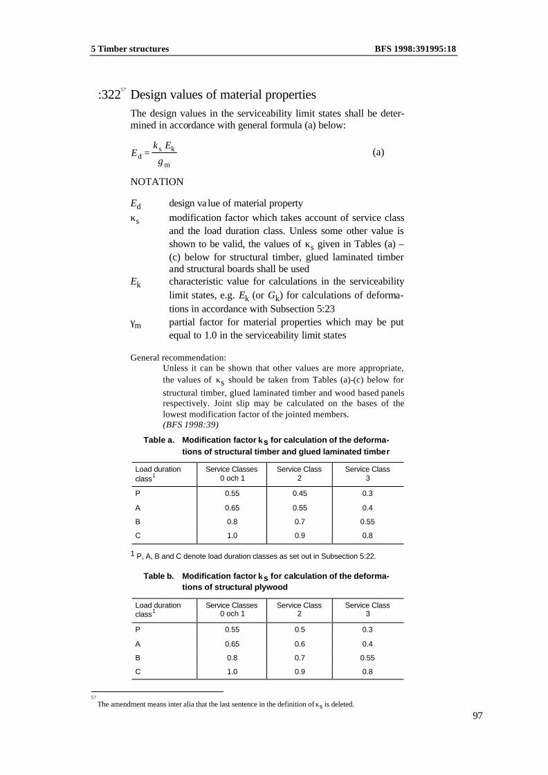
5 Timber structures BFS 1998:391995:18
97
:32257 Design values of material properties The design values in the serviceability limit states shall be deter-mined in accordance with general formula (a) below:
EE
ds k
m=
κ
γ (a)
NOTATION
Ed design value of material property κs modification factor which takes account of service class
and the load duration class. Unless some other value is shown to be valid, the values of κs given in Tables (a) – (c) below for structural timber, glued laminated timber and structural boards shall be used
Ek characteristic value for calculations in the serviceability limit states, e.g. Ek (or Gk) for calculations of deforma-tions in accordance with Subsection 5:23
γm partial factor for material properties which may be put equal to 1.0 in the serviceability limit states
General recommendation:
Unless it can be shown that other values are more appropriate, the values of κs should be taken from Tables (a)-(c) below for structural timber, glued laminated timber and wood based panels respectively. Joint slip may be calculated on the bases of the lowest modification factor of the jointed members. (BFS 1998:39)
Table a. Modification factor κs for calculation of the deforma-tions of structural timber and glued laminated timber
Load duration
class1 Service Classes
0 och 1 Service Class
2 Service Class
3
P 0.55 0.45 0.3
A 0.65 0.55 0.4
B 0.8 0.7 0.55
C 1.0 0.9 0.8
1 P, A, B and C denote load duration classes as set out in Subsection 5:22.
Table b. Modification factor κs for calculation of the deforma-tions of structural plywood
Load duration class1
Service Classes 0 och 1
Service Class 2
Service Class 3
P 0.55 0.5 0.3
A 0.65 0.6 0.4
B 0.8 0.7 0.55
C 1.0 0.9 0.8
57
The amendment means inter alia that the last sentence in the definition of κs is deleted.

BFS 1998:39 5 Timbers structures
98
1 P, A, B and C denote load duration classes as set out in Subs ection 5:22. Table c. Modification factor κs for calculation of the de-
formations of K board, K-particleboard and flooring grade particleboard
Load duration class1 Service Classes 0 och 1
Service Cclass 2
P 0.3 0.2
A 0.4 0.3
B 0.55 0.4
C 0.8 0.55
1 P, A, B and C denote load duration classes as set out in Subsection 5:22.
:323 Floor vibration For a timber floor, account shall be taken of the risk of excessive vibration.
General recommendation:
The vibration susceptibility of a floor structure may be assessed in accordance with Boverket's handbook Vibration, induced de-formation and accidental actions. For residential floors with solid timber beams in the direction of the main span, the follow-ing simplified calculation method may be used in assessing the vibration susceptibility of the floor.
The deflection of a single beam in a timber floor structure should not exceed 1.5 mm under the action of a point load of short duration (κs=1), the design value of which is 1.0 kN. The beam is assumed in the calculation to be simply supported and loaded at its midpoint. Any distribution of load to adjacent beams may be taken into account. (BFS 1995:18)
If interaction between the beams and floor boards is utilised in the calculation, the joints should be comprised in the addi-tional inspection in accordance with Section 2:6. (BFS 1995:18)
5:33 Design by testing (BFS 1995:18) The design value of the resistance Rd in the ultimate limit states shall be determined in accordance with formula (a) below.
RR
dr k
mp n
=κ
γ γ (a)

5 Timber structures BFS 1998:391995:18
99
NOTATION Rk characteristic value of resistance in accordance with Sub-
section 2:33 (BFS 1995:18) κr factor for reduction of the resistance with respect to the
effect of moisture and load duration in accordance with Subsections 5:21 and 5:22
γn partial factor for safety class in accordance with Subsec-tion 2:115
γmp partial factor for resistance which may be put equal to γ m in accordance with Subsection 5:3121
General recommendation:
Design values in the serviceability limit states can be determined in accordance with Boverket's handbook Design by testing.
5:4 Materials General recommendation:
General provisions regarding materials are given in Section 2:4. The following subsections give examples of materials and
fasteners which satisfy these requirements for timber structures.
5:41 Structural timber General recommendation:
Where lateral instability can occur, the initial curvature of a structural element should be limited to 1/300 of the length. (BFS 1998:39)
:41158 Visually graded structural timber General recommendation:
Visually graded sawn or planed structural timber is to be as-signed to Strength Classes K30, K24, K18 or K12 if it is graded and marked as follows.
58
The amendment means inter alia that the last sentence in the general recommendation is deleted.

BFS 1998:39 5 Timbers structures
100
K30: Marked T30 and graded in accordance with —– [1] Instructions for grading and marking of T tim-
ber (stress graded timber), (Edition 5, 1981), published by
the Swedish Stress Graded Timber Association, —– [2] Grading rules for structural timber, Annex A to
Danish Standard DS 413 (Edition 4, 1982), —– [3] The Finnish grading rules drawn up by VTT,
Sahatavaran lujuuslaji ttelupas, —– [4] Quality requirements for structural timber, Nor-
wegian Standard NS 3080 (Edition 2, 1988).
Marked T3 and graded in accordance with – [5] SS 23 01 20

5 Timber structures BFS 1998:391995:18
101
K24: Marked T24 and graded in accordance with – [1],[2],[3] and [4] above, Marked T2 and
graded in accordance with [5] above.
K18: Marked T18 and graded in accordance with – [1],[3] or [4] above, Marked T1 and graded in accordance with [5] above. K12: Marked T0 and graded in accordance with [5] above Marked or unmarked timber – which satisfies the requirements of SS 23 01 30, – of Grade B or better in accordance with Nordic
Wood − Grading rules for sawn pine and spruce timber 1994. The bow shall not, however, exceed 5 mm over a length of 2 m. (BFS 1998:39)
:412 Mechanically stress graded structural timber General recommendation:
Mechanically stress graded structural timber which is graded and inspected in accordance with SS−EN 519 and marked in accor-dance with Chaper 4 of the approval rules (PFS 1978:3) of the Swedish Board of Physical Planning and Building, Mechanically stress graded structural timber, with the exception of d) in Clause 4:1, is regarded as structural timber in Strength Classes K35, K30, K24 and K18.
When applying the requirements for additional visual grading in SS−EN 519, Strength Class C18 in accordance with SS−EN 338 is to be substituted by Strength Class K18 according to Sub-section 5:411. (BFS 1998:39)
:413 Finger jointed structural timber General recommendation:
Finger jointed structural timber which is produced and inspected in accordance with SS−EN 385 and marked in accordance with Chapter 4 of the approval rules (PFS 1975:7) of the Swedish Board of Physical Planning and Building, Finger jointed stru c-tural timber, with the exception of the text regarding the Board’s mark of approval in Clause 4:1, is regarded as structural timber in Strength Classes K35, K30, K24, K18 and K12. For structural timber in Strength Class K12, the strength of the joint should not be less than that of Strength Class K18. (BFS 1998:39)
:414 Round timber General recommendation:
Round timber without loose rot or deep holes made by wood de-stroying insects is regarded as structural timber of Strength Class K30. Round timber for permanent structures should be free of bark.

BFS 1998:39 5 Timbers structures
102
:415 Glued structural timber (BFS 1998:39) General recommendation:
Glued timber components made up of two or three laminates with the grain oriented along the longitudinal direction of the component are regarded as glued structural timber. Glued struc-tural timber should be produced, inspected and marked in accor-dance with Rules for Production Control of Glued Laminated Timber and Glued Structural Timber, Swedish Council for Laminated Timber Control, 1997:1. (BFS 1998:39)
5:42 Glued laminated timber

5 Timber structures BFS 1998:391995:18
103
5:42 Glued laminated timber General recommendation:
Glued timber components made up of not less than four lami-nates with the grain oriented along the longitudinal direction of the component are regarded as glued laminated timber. Glued laminated timber should be produced, inspected and marked in accordance with Rules for Production Control of Glued Lami-nated Timber and Glued Structural Timber, Swedish Council for Laminated Timber Control, 1997:1.
Where lateral instability can occur, the initial curvature of a structural element should be limited to 1/500 of the length. (BFS 1998:39)
5:43 Structural board General recommendation:
Structural board of K plywood and K board should have the properties specified in, and should be produced, inspected and marked in accordance with, the approval rules (1975:5) of the Swedish Board of Physical Planning and Building, Wood based board materials – manufacture and control.
Structural board of K particleboard and flooring grade parti-cleboard should have the properties specified in, and should be produced, inspected and marked in accordance with, Product Rules No 5, Particleboard , of the Nordic Committee for Build-ing Regulations NKB.
5:44 Joints
:441 Mechanical connectors General recommendation:
Wire nails with a cross section d < 6 mm and a least characteris-tic failure moment in accordance with Table (a) below should be used. For square and grooved nails d (mm) is the least side di-mension and for round nails the diameter.
In bolted joints, bolts in Strength Class 4.6 in accordance with Swedish Standard SS 2265, and nuts in Strength Class 4 in accordance with SS 2268, should be used.
In bolted joints and in joints with screws, steel washers of not less than 0.3d thickness and a lateral dimension (diameter or length of side) not less than 3d should be used, where d is the bolt or screw diameter.

BFS 1998:39 5 Timbers structures
104
Screws complying with Swedish Standards SMS 1573-1575 and SS 2020 should be used.
Table a. Characteristic yield moments for wire nails
Type of nail Yield moment (Nmm)
Square and grooved
Round 10 (20-d) d 3
6.7 (20-d) d 3
:442 Adhesives General recommendation:
Adhesives which comply with the requirements for Adhesive Type I in accordance with Swedish Standard SS-EN 301 can be used for structures in all service classes. Adhesives which com-ply with the requirements for Adhesive Type II can be used for structures in Service Classes 0 – 2.

5 Timber structures BFS 1998:391995:18
105
5:5 Execution and workmanship General recommendation:
General provisions regarding execution and workmanship are set out in Section 2:5.
In this Section, examples are given of execution and work-manship which complies with these provisions.
5:51 Timber General recommendation:
The face of a timber component which is joined to another tim-ber should not have wane, loose knots or similar defects to such an extent that the strength of the joint is inadequate. Timber which splits, for instance while being nailed, is to be rejected.
Finger jointed structural timber may be used in a loadbearing structure provided that
a) the timber is produced, inspected and marked in accor-dance with the provisions of Subsection 5:413,
b) the structure is designed so that failure of a single finger joint does not cause collapse of essential parts of the structure as a whole.
The condition in b) is considered to have been complied with in structures comprising closely spaced beams or trusses, and implies that finger jointed structural timber should be used with care in structures in Safety Class 3.
Finger jointed structural timber should not be used in scaf-folds or other structures subject to impact loading.

BFS 1998:39 5 Timbers structures
106
5:52 Joints
:521 Nailed joints General recommendation:
In a joint between a structural (K) board and timber, the nails which transmit load should have adequate pointside penetration in the timber.
For nails of d > 5 mm, the timber should be predrilled using a drill of 0.8–0.9 d.
:522 Punched nail plate joints General recommendation:
Punched nail plate joints may be made in accordance with the approval rules (1974:4), Punched nail plate joints, of the Swed-ish Board of Physical Planning and Building.
:523 Bolted and screwed joints General recommendation:
Holes for bolts should be drilled so that the bolts must be forced in. Bolts should if necessary be retightened after the timber has dried.
Holes for screws should be drilled for the unthreaded portion so that there is a tight fit to the shank diameter, and for the threa-ded portion with a drill of 0.8 – 0.9 times the core diameter.
:524 Glued joints General recommendation:
Glued joints in glued structures which are not to be classified as glued laminated timber in accordance with Subsection 5:42 should be constructed in accordance with the approval rules (PFS 1975:6), Glued timber structures. Production and inspection, of the Swedish Board of Physical Planning and Building.
In nail pressure gluing and screw pressure gluing, the appro-priate adhesive and the distance between nails and screws should be determined on the basis of trials.
5:6 Supervision and control The values of the partial factors γm and γmp set out in this section presuppose that the supervision and control specified in Section 2.6 is carried out. (BFS 1995:18)
5:61 Basic inspection General recommendation:
Basic inspection of timber structures should comprise inspection of materials, joints, products and workmanship.
5 Timber structures BFS 1998:391995:18
107
Site inspection should check that the quality and dimensions of joints, support details and timber conform to the requirements and conditions given on drawings and in other construction documents, and the execution and workmanship to the provisions of Section 5:5. In a joint the number of connectors should also be checked.
5:62 Additional inspection General recommendation:
Additional inspection of timber structures should comprise checks on —– joints in glued laminated structures —– protection of timber in structures in contact with soil, —– glued joints used to transmit force, and —– erection of structures subject to production control which have been designed using the partial factor γm = 1.15.

108

6 Masonry structures BFS 1998:39
109
6 MASONRY STRUCTURES
6:1 Requirements General recommendation:
General requirements are set out in Section 2:1.
6:11 Durability Masonry structures shall be designed, detailed and constructed with due regard to harmful degradation.
General recommendation:
Examples of harmful degradation are corrosion and frost attack. Examples of materials which are considered to comply with
the requirements concerning corrosion resistance are given for wall ties in Subsection 6:44 and for reinforcement in Subsection 6:45. Examples of exposure classes for reinforcement are given in Subsection 6:3128.
Bricks and blocks which are found frost resistant in tests by a method according to Table (a) below are considered to comply with the requirement concerning frost resistance. Clay bricks which, according to Section 5.6.1 of SS 22 01 11, are of Class F2 can be regarded as frost resistant. Clay bricks of Class F1, mo d-erately frost resistant, may be used in facades in regions and in positions where the climatic conditions are moderate if – earlier documented experiences with the type of clay bricks in question are good and – the detailing of the structure has been designed or is other-wise judged to limit moisture influences.
Some examples of regions where the climatic conditions are severe are Driving Rain Zone 2, 3 and 4 according to Moisture handbook – practice and theory, Section 93:4. Driving rain is, however, only one of several factors which influence the durabil-ity of masonry. (BFS 1998:39)
Bricks and blocks shall be dimensionally stable.
General recommendation:
The requirement concerning dimensional stability in conjunction with changes in moisture content may be considered to have been complied with if the change in length in shrinkage tests by a method according to Table (a) below does not exceed the follow-ing values: —– mean value for test specimens 0.05% —– maximum individual value 0.06%.

BFS 1998:39 6 Masonry structures
110
Table a. Examples of suitable test methods for frost resistance and dimensional stability
Material Frost resis-tance
Dimensional stability
Clay bricks and sand lime bricks
SIS 22 01 11 SIS 22 01 11
Concrete bricks, concrete blocks and lightweight aggregate blocks
SS 22 72 31 SS 22 72 31
Autoclaved aer-ated concrete blocks
–
SS-EN 680
(BFS 1998:39)
6:2 Design assumptions General recommendation:
General design assumptions are given in Section 2:2.
6:21 Characteristic values of material properties for masonry structures The characteristic values of the strength, modulus of elasticity and ultimate compressive strain of masonry structures which are set out in this section (Section 6:2) apply if the following conditions are satisfied: —– The cross sectional area of the masonry structure is not less than 0.04 m2, allowance being made for chases and recesses. —– The masonry structure is laid to bond with the perpends stag-gered not less than 60 mm for bricks and not less than one quarter of the length of a block. —– The masonry structure is constructed with a least nominal thickness in accordance with Table (a) in Subsection 6:311. —– The masonry is constructed in accordance with the first clause of Regulations for Execution and Workmanship, of Hus AMA 98 Chapter FS (General Material and Workmanship Specifications for Buildings). (BFS 1998:39)
General recommendation:
For masonry thinner than 150 mm a deduction from the cross section should also be made with respect to mortar joints if these are raked out or indented more than 3 mm.
:21159 Compressive strength The characteristic values set out in Table (a) below shall be applied for the compressive strength ƒck perpendicular to bed joints and parallel to any holes in bricks and blocks, and for the ult imate compressive strain εu under actions of long duration. These values apply if the following conditions are satisfied:
59
Lastest wording BFS 1995:18. The amendment means inter alia that the value for compressive strength for hollow concrete block masonry with Class A mortar is deleted.

6 Masonry structures BFS 1998:39
111
—– The average joint thickness is not greater than 15 mm for bricks and blocks and not greater than 3 mm for thin joint masonry. —– The masonry is to be laid on a full bed of mortar except in the case of shell bedded clinker block masonry. For shell bedded clinker blocks where not more than the middle third of the joint is left unfilled, the tabulated values are to be multiplied by the factor 2/3. This compressive strength is in such a case assumed to be uni-formly distributed over the entire width of the joint (the thickness of the wall). If not more than the middle sixth of the width of the bed joint is left unfilled in clinker block masonry, the compressive strength need not be reduced. —– The masonry is constructed with the perpends completely filled. Masonry of clinker blocks may however be constructed with the perpends completely unfilled, without any reduction in the ver-tical compressive strength (fck,tra). On the other hand, the compres-sive strength parallel to the bed joints is to be reduced when the perpends are unfilled. (BFS 1998:39)
General recommendation:

BFS 1998:39 6 Masonry structures
112
General recommendation: Clinker blocks wider than 150 mm should be laid with shell bed-ding.

6 Masonry structures BFS 1998:39
113
Table a. Characteristic values of the compressive strength fck and the ultimate compressive strain εu under actions of long duration for different masonry structures (BFS 1995:18)
Bricks/blocks Strength Class
fck (MPa)
Mortar Class according to SS 13 75 19
ε u1
(‰)
A B C D Clay bricks 15
25
35
45
55
65
5.8
7.5
8.9
10
11.1
12.1
4.6
6.0
7.1
8.0
8.9
9.7
3.3
4.3
5.0
5.7
6.3
6.9
1.34
1.84
2.34
2.34
2.34
2.34
4
4
4
4
4
4
Sandlime bricks 25 – 6.03 4.33 – 4
Concrete bricks 25 7.5 6.0 – – 4 Hollow concrete blocks
5
10
1.7
2.4
1.7
2.4
1.5
2.0
–
–
4
4 Solid concrete blocks 10
15
3.8
4.7
3.8
4.7
3.0
3.7
–
–
4
4
Autoclaved aerated concrete blocks 2
1.7
2.3
3
5
–
–
–
–
1.1
1.4
1.7
2.7
1.1
1.4
1.7
2.1
–
–
–
–
4
4
4
4
Clinker blocks
2
3
5
10
–
–
–
–
1.8
2.4
3.4
4.3
1.2
1.6
2.2
3.4
0.54
0.54
0.54
0.54
2.5
2.5
2.5
2.5
(BFS 1998:39) 1 The values apply for Class B or C mortar. For Class A mortar the values of εu
shall be multiplied by the reduction factor 0.75 and for Class D mortar by the factor 2.1. (BFS 1998:39)
2 The strength classes given correspond to Quality Groups 400, 450, 500 and 600. The designation for the quality group is based on the nominal dry density
of the autoclaved aerated concrete in kg/m3. 3 Refers to masonry cement A as binder. 4 On condition that the masonry is never subjected to temperatures below +0°C
and its mean temperature over 24 hours is not under +5°C, neither during construction nor as finished structure, 40% higher values may be applied.See also Subsection 6:51. (BFS 1998:39)
If the average thickness of the bed joints is greater than 15 mm in brick or block masonry of strength class higher than 5, the tabu-lated values of ƒck shall be reduced. For 30 mm joints the tabu-lated values of ƒck shall be multiplied by the reduction factor 0.6. Linear interpolation is to be applied for joint thicknesses between 15 and 30 mm.
For blockwork of strength class not higher than 5, no reduction need be made for average joint thickness up to 20 mm. For 30 mm bed joints the tabulated values of ƒck shall be multiplied by the re-

BFS 1998:39 6 Masonry structures
114
duction factor 0.8. Linear interpolation is to be applied for joint thicknesses between 20 and 30 mm.
For loadbearing masonry acted upon by vertical loads, the joint thickness shall not exceed 30 mm on average or 35 mm for an in-dividual joint.
For the characteristic strength parallel to bed joints in masonry of hollow bricks or hollow blocks, the tabulated values of ƒck shall be multiplied by the reduction factor 0.4. Also in the case of clinker block masonry laid on a full bed of mortar or shell bedded, with the perpends open, the tabulated values of ƒck shall be mult i-plied by the reduction factor 0.4 for compressive strength parallel to the bed joints.
:212 Flexural tensile strength For masonry subject to flexure due to transverse action (wind ac-tion, earth pressure etc) the characteristic values of the flexural ten-sile strength, ftk,par parallel to the bed joints (vertical moment vec-tor) and ftk,tra perpendicular to the bed joints (horizontal moment vector) tabulated below shall be applied unless other values can be shown to be applicable. Table a. Characteristic values of the flexural tensile strength of
masonry, ftk,par and ftk,tra.
Bricks/blocks Strength class
Mortar Class according to SS 13 75 19
ftk,par
(MPa)
ftk,tra
(MPa)
Hollow clay bricks
Solid clay bricks
15—–65
15—–65
A—–B
A—–B
1.1
1.1
0.3
0.25
Sandlime bricks 25 B 0.9 0.1
Concrete bricks 25 B 0.9 0.2
Hollow concrete blocks
5—–10 A—–B 0.4 0.2
Solid concrete blocks
10—–15 A—–B 0.4 0.2
Autoclaved aer-ated concrete blocks
1.7 2.3 3 5
B B B B
0.1 0.2 0.25 0.25
0.1 0.1 0.2 0.2
Clinker blocks 2 B 0.15 0.15
3 5 10
B B B
0.3 0.3 0.3
0.15 0.15 0.15
(BFS 1995:18)
For masonry in Mortar Class C the tabulated values shall be
multiplied by the reduction factor 0.8. For blockwork masonry the tabulated values apply when the
blocks are laid with the perpends staggered by half a block or by

6 Masonry structures BFS 1998:39
115
250 mm. The tabulated values apply to masonry with filled joints. For clinker block masonry laid on shell bedding and with the per-pends left open, the values shall be multiplied by the reduction fac-tor 0.75, and for blocks laid on a full bed of mortar and with the perpends left open, only ftk,par shall be multiplied by the reduction factor 0.75.
For masonry wall beams subject to flexure in the plane of the wall due to the dead load of the wall and applied vertical load if any, the tabulated values of ftk,par shall be used as the characteristic value of the tensile strength in flexure in bonded masonry without soldier courses or brick on edge courses.
For wall beams with soldier courses or brick on edge courses the values of ftk,tra in Table (a) shall be used as characteristic val-ues.
:21360 Shear strength General recommendation:
The characteristic value of shear strength parallel to bed joints, fvk,par may be calculated from formulae (a)-(e) below: For masonry consisting of clay bricks fvk,par = 0.10 + 0.75σn but ≤ 1.0 MPa (a)
sandlime bricks fvk,par = 0.10 + 0.50σn but ≤ 0.6 MPa (b)
thin joint autoclaved aerated concrete blocks fvk,par = 0.25 + 0.50σn but ≤ 0.8 MPa clinker blocks fvk,par = 0.15 + 0.90σn but ≤ 1.1 MPa ((d) concrete bricks, hollow and solid concrete blocks, and autclaved aerated concrete blocks fvk,par = 0.15 + 0.50σn but ≤ 0.6 MPa (e)
where σn is the mean compressive stress in the combination of actions concerned. (BFS 1998:39)
Formulae (a)– (e) apply for Mortar Class A or B. For Class C
the value of fvk,par is to be multiplied by the reduction factor 0.8. For clinker blockwork laid on shell bedding and with open per-pends, fvk,par is to be calculated from fo rmula (b).
The characteristic value of shear strength, fvk,tra, perpendicu-lar to bed joints, i.e. in a vertical cross section, can be put equal to 0.8 MPa for Mortar Classes A, B and C. In applying this value it is assumed that the shear force is uniformly distributed over the cross sections of the bricks or blocks. The perpends should not therefore be included in the calculations. (BFS 1998:39)
Formulae (a) – (e) presuppose a strength class not less than 15 for bricks and not less than 1.7 for blocks.
60
Latest wording BFS 1995:18.
BFS 1998:39 6 Masonry structures
116
:21461 Modulus of elasticity The characteristic value Ek of the modulus of elasticity of masonry under short term loading shall be assumed constant for stresses be-tween the design value of the flexural tensile strength, ftd, and 0.6 fcd, where fcd is the design value of the compressive strength.
General recommendation:
61
Latest wording BFS 1995:18.
6 Masonry structures BFS 1998:39
117
General recommendation: For normal masonry in Mortar Class A, B or C, the approximate value is Ek = 400fck for solid clay bricks and sandlime bricks (a) Ek = 700fck for hollow clay bricks and thin joint auto- claved aerated concrete blocks (b) Ek = 1400fck for clinker blocks (c) Ek = 1000fck for concrete bricks, hollow and solid concrete blocks, and autoclaved aerated concrete blocks (d) (BFS 1998:39) Where a more accurate value of the modulus of elasticity is re-quired, it should be determined by tests.
6:22 Deviations from size and shape General recommendation:
Examples of deviations from size and shape which should be taken into consideration in design are given in Subsection 6:51. (BFS 1998:39)
6:3 Design by calculation and testing (BFS 1995:18)
General recommendation: General provisions regarding design are set out in Section 2.3. (BFS 1995:18)
6:31 Design in the ultimate limit states
:311 Calculation of forces and moments Masonry shall have the least nominal thickness set out in Table (a) below. The table presupposes that the deviations from size and shape are not greater than those specified in Subsection 6:51.

BFS 1998:39 6 Masonry structures
118
Table a. Least nominal wall thickness for masonry of different heights
Height of masonry Least nominal wall thickness (mm)
Loadbearing wall
Veneer wall
Not more than 2 storeys, < 6 m 85 60
More than 2 storeys, > 6 m 120 85
Cracking of the masonry shall be taken into consideration if
they are of essential significance for the distribution of forces and moments in the structure. (BFS 1998:39)
Restraint forces shall be calculated with reference to the mode of action of the structure in the ultimate limit state.
:312 Calculation of resistance

6 Masonry structures BFS 1998:39
119
:312 Calculation of resistance :3121 Design values of material properties for masonry
The design values of the strength fd and modulus of elasticity Ed of masonry in the ultimate limit states shall be determined from for-mulae (a) and (b) below.
ff
dk
m n=
γ γ (a)
E Ed
k
m n=
γ γ (b)
NOTATION fk characteristic value of the strength of the masonry in ac-
cordance with Subsections 6:211, 6:212 and 6:213 Ek characteristic value of the modulus of elasticity of the ma-
sonry in accordance with Subsection 6:214 γm partial factor for the resistance of the masonry in accor-
dance with Subsection 6:3123 γn partial factor for safety class in accordance with Subsection
2:115
If a high value of the modulus of elasticity is unfavourable in the ultimate limit states, Ed shall be put equal to Ek.
In determining the shear capacity Rv, consideration shall be given to the fact that, as set out in Subsection 6:213, the shear strength parallel to the bed joints is different from that perpendicu-lar to these. The shear strength parallel to the bed joints, fvd,par, may be utilised only in the part of the cross section where axial tensile stress does not simultaneously occur. (BFS 1998:39)
BFS 1998:39 6 Masonry structures
120
:3122 Design values of material properties for reinforcementIn the ultimate limit states the design value of the tensile strength, fstd, shall be determined from formula (a) below.
ff
stdyk
m=
γ γ n (a)
NOTATION fyk characteristic value of strength for reinforcement. The
value of fyk for B500B and Ks 60 S shall be taken from Table (a) in Subsection 7:231 (BFS 1998:39)

6 Masonry structures BFS 1998:39
121
γm partial factor for the resistance of reinforcement in accor-dance with Subsection 6:3123
γn partial factor for safety class in accordance with Subsection 2:115.
General recommendation:
For hot rolled reinforcement (e.g. B500B), the design value fscd of the compressive strength should be assumed to have the same numerical value as the tensile strength fstd. For cold worked rein-forcement the value of fscd should be assumed to be equal to not more than 0.5 fstd. (BFS 1998:39)
The characteristic value of the modulus of elasticity Esk of rein-
forcement shall be assumed to be 200 GPa. In the ultimate limit states the design value Esd shall be deter-
mined from formula (b) below.
EE
sdsk
n=
105. γ (b)
In design for accidental actions and with respect to progressive col-lapse, Esd shall be put equal to Esk.
:3123 Partial factor γm for masonry, wall ties and reinforcement
The value of the partial factor γm for masonry, wall ties and rein-forcement shall be determined from Table (a).

BFS 1998:39 6 Masonry structures
122
Table a. Prescribed partial factors γm for resistance in the ultimate limit states in general
Partial factor γm
Execution Class I Execution Class II
1 2 1 2
Masonry
In general Nonloadbearing walls subject to wind action
2.3 1.9
1.8 1.5
2.9 2.4
2.3 1.9
Wall ties
Strength Anchorage
1.9 2.5
1.5 2.0
2.4 3.1
1.9 2.5
Reinforcement
Strength Anchorage
1.9 2.5
1.5 2.0
– –
– –
The values of the partial factor γm in column 1 in each execu-
tion class apply for the design of masonry structures when the products used (bricks, blocks, mortar or reinforcement) have not been subject to factory production control in accordance with Sec-tion 1:4.
The values of the partial factor γm in column 2 in each execu-tion class apply for the design of masonry structures when all the products used (bricks, blocks, mortar or reinforcement) have been subject to factory production control in accordance with Subsection 1:4.
:3124 Stress-strain curves
General recommendation: The stress-strain curve in Figure (a) below can be applied for masonry in calculating —– the moment capacity of reinforced masonry, —– deformations in reinforced masonry, and —– stability, but only for Mortar Classes A, B and C and if the mean compressive strain is not greater than 0.6 fcd. (BFS 1998:39)
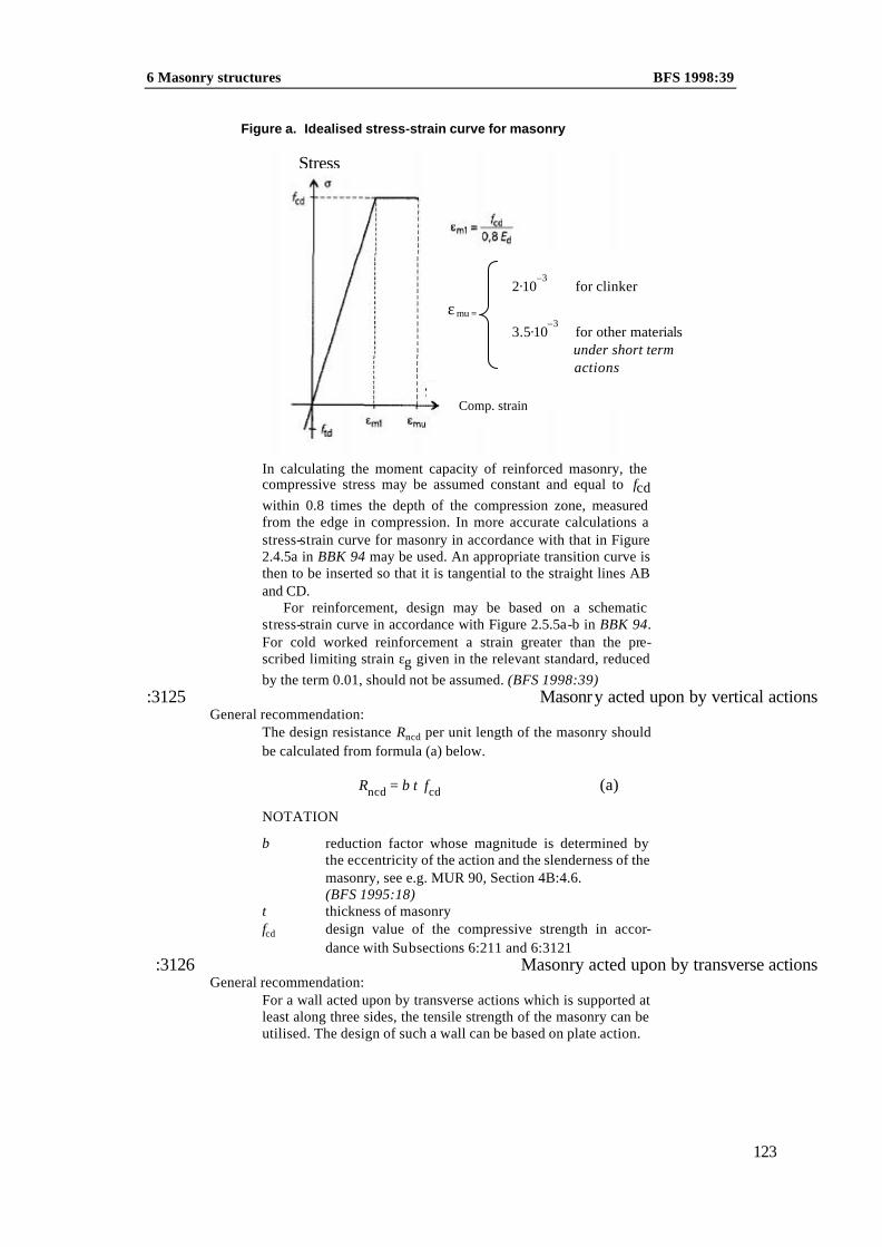
6 Masonry structures BFS 1998:39
123
Figure a. Idealised stress-strain curve for masonry
In calculating the moment capacity of reinforced masonry, the compressive stress may be assumed constant and equal to fcd within 0.8 times the depth of the compression zone, measured from the edge in compression. In more accurate calculations a stress-strain curve for masonry in accordance with that in Figure 2.4.5a in BBK 94 may be used. An appropriate transition curve is then to be inserted so that it is tangential to the straight lines AB and CD.
For reinforcement, design may be based on a schematic stress-strain curve in accordance with Figure 2.5.5a-b in BBK 94. For cold worked reinforcement a strain greater than the pre-scribed limiting strain εg given in the relevant standard, reduced by the term 0.01, should not be assumed. (BFS 1998:39)
:3125 Masonry acted upon by vertical actions General recommendation:
The design resistance Rncd per unit length of the masonry should be calculated from formula (a) below.
R t fncd cd= β (a)
NOTATION
β reduction factor whose magnitude is determined by the eccentricity of the action and the slenderness of the masonry, see e.g. MUR 90, Section 4B:4.6.
(BFS 1995:18) t thickness of masonry fcd design value of the compressive strength in accor-
dance with Subsections 6:211 and 6:3121 :3126 Masonry acted upon by transverse actions
General recommendation: For a wall acted upon by transverse actions which is supported at least along three sides, the tensile strength of the masonry can be utilised. The design of such a wall can be based on plate action.
εmu =
Comp. strain
2·10–3
for clinker
3.5·10–3
for other materials under short term actions
Stress

BFS 1998:39 6 Masonry structures
124
When a wall is supported along two vertical sides, i.e. in the case of wall strips spanning in one direction horizontally, the tensile strength in flexure ftd,par parallel to the bed joints, in ac-cordance with Subsections 6:212 and 6:3121, can be util ised.
For structures in Safety Classes 2 and 3, the resistance with respect to transverse actions shall not be based only on the tensile strength in flexure perpendicular to bed joints. General recommendation:
For unreinforced masonry the resistance can be calculated in ac-cordance with the elastic theory for an isotropic slab. In compli-cated cases, e.g. walls with openings, approximate solutions based on subdivision of the masonry into elements may be ap-plied. Attention must be paid to the essential continuity and elas-ticity conditions.
The calculated resistance at the first flexural crack is nor-mally to be taken as the ultimate limit. If after cracking the ma-sonry can resist larger transverse actions, the collapse action is the ultimate limit.
As an alternative to calculation using the elastic theory, a method based on the mode of action of the masonry in the ulti-mate limit state may be applied.
The resistance with respect to horizontal actions may also be calculated on the basis of arching action without utilisation of the tensile strength. This applies on condition that the supports are sufficiently rigid so that the arching forces in the plane of the wall can be resisted.
:3127 Local pressureLocal pressure shall be limited to ensure that splitting does not give rise to disruption of function or a reduction in the resistance or du-rability of the structure. General recommendation:
Local pressure is to be considered to exist when the size of the contact area in the longitudinal direction of the masonry is less than twice the thickness of the masonry or less than one third of the length of the masonry.
:3128 Reinforced masonryMasonry in a building of more than two storeys and masonry with in-situ reinforcement shall be constructed to Execution Class I. Masonry with in-situ reinforcement in single -dwelling houses of not more than two storeys and masonry reinforced only to take up movement forces may, however, be constructed to Execution Class II. Mortar in reinforced masonry shall be of Class A or B. (BFS 1998:39)
General recommendation:
The moment capacity Rmd of the masonry should be calculated from formula (a) below.
R A dA f
ff
bdmd s
s std
cdstd=
−1 0 5. . (a)

6 Masonry structures BFS 1998:39
125
The moment capacity Rmd calculated according to formula (a) presupposes that the cross section is normally reinforced and should therefore satisfy condition (b) below. (BFS 1998:39)
R bd fmd ≤ 0 3 2. c d (b)
NOTATION As area of tensile reinforcement b width of wall strip or wall beam d effective depth fstd,fcd design values in accordance with Subsections 6:3122
and 6:3121
When formula (b) is applied to masonry of clinker blocks, the factor 0.3 should be replaced by 0.2. The mechanical reinforce-ment content of the cross section, ω, may also be verified in the same way as for concrete structures at which εcu is put equal to εmu in accordance with Subsection 6:3124. (BFS 1998:39)
The shear capacity should be checked both parallel and per-pendicular to the bed joints. The resistance of masonry in shear, Rvd, should be calculated from formula (c) below
Rvd = bd fvd (c)
where fvd is the design value of shear strength in the direction concerned in accordance with Subsections 6:213 and 6:3121.
A masonry wall in which joint reinforcement is utilised to re-sist transverse action, e.g. wind action or earth pressure, may be designed as a reinforced wall strip spanning in one direction or as a two-way spanning slab.
Reinforcement in masonry shall be anchored so that it can in each section resist the forces which occur under design loading. General recommendation:
For ribbed bars laid in mortar of Class A or B the bond stress may be assumed to be uniformly distributed over the surface area of the reinforcement. The characteristic value fbk of bond strength should be assumed to be not greater than 1.0 MPa. (BFS 1998:39)
All reinforcement in the span should be carried not less than 200 mm beyond the edge of the support.
In masonry reinforced to resist concentrated loads greater an-chorage lengths may be required.

BFS 1998:39 6 Masonry structures
126
Lap splices shall be constructed in such a way that the ends of bars have the required anchorage, and so that the force at the section can be transmitted from one bar to the other. The increased risk of splitting where laps are near one another shall be taken into con-sideration. Reinforcement in beams and walls required to carry load shall not be lapped.
General recommendation:
The lap length in reinforcement for transverse action should be not less than 500 mm. The midpoint of the lap should be not less than 1.0 m from the vertical support section.
In bed joints with two reinforcing bars the midpoints of the lap splices should be staggered by not less than 1.0 m. The same applies to adjacent lap splices at different levels in the masonry.
The limiting values of diameter, joint thickness and clear dis-
tance between reinforcing bars, set out in Table (a) below, shall apply to reinforcement in bed joints.
Table a. Limiting values of bar diameter, least joint thickness and
least clear distance
Reinforcing steel Bar diameter ∅ (mm)
Least joint thickness (mm)
Least clear distance
(mm)2
min max
Ribbed bar 6 81 ∅ + 7 2 ∅
Ladder and framework type reinforcement
3.5 6 ∅ + 7 –
(BFS 1998:39) 1 For reinforcement placed in special grooves in block masonry and surrounded by not less than 10 mm mortar, a bar diameter up to 12 mm may be used.
2 Lapped bars are however to be placed in contact.
General recommendation: The values of minimum cover set out in Table (b) below for dif-ferent grades of reinforcement and for the exposure classes set out in Table (c) overleaf satisfy the requirements regarding cor-rosion resistance in Subsections 2:13 and 6:11.

6 Masonry structures BFS 1998:39
127
Table b. Minimum cover in the horizontal direction for masonry reinforcement
Exposure Class Cover (mm)
ob1 fz2 rf3 eb4
1. Environment of insignificant ag-gressivity to reinforcement
25 15 10 15
2. and 3. Environment of moder-ate/high aggressivity to reinforce-ment
–
–
15
–
1 ob = untreated steel 2 fz = zinc coated steel, min. Fe/Zn 45 SS 3192 (BFS 1998:39) 3 rf = stainless acid resistant SS Steel 2340 or 2343, or cold drawn 18/8
steel grade SS 2331 4 eb = steel treated with epoxy
Table c. Examples of exposure classes for masonry
structures
Exposure Class Type of structure
1 (A1)1 Internal walls,the inner leaves of cavity walls, the warm inside of block walls, basement walls with two stage waterproofing
2 och 3 (A2, A3)1 Other walls such as facades, basement walls and internal walls in aggressive industrial at-mospheres
1 Exposure classes according to BBK 94 Subclause 7.3.2.2 :3129
62
Wall ties in veneer walls Wall ties and their anchorage shall be designed for forces due to wind action and temperature movements in the masonry. (BFS 1998:39)
In design with respect to wind action any imposed deformations due to e.g. temperature movements in the masonry shall be taken into consideration.
General recommendation:
The design values, which may be assumed for temperature movements in an arbitrary direction, are 0.25 mm/m for clay bricks and clinker blocks, 0.3 mm/m for sandlime bricks and 0.4 mm/m for concrete bricks. When these values are used in the same combination of actions as wind actions, the effect of fa-tigue may be assumed to have been taken into consideration. (BFS 1998:39)
Anchorage of wire type wall ties in completely filled joints should be effected by bending the end of the wall tie as shown in Figure (a) below. If the wall tie is of another type or it is fixed in some other way or if mortar of Class D is used, its anchorage and deformation properties should be determined by tests. (BFS 1998:39)
62
The amendment means inter alia that the second paragraph in the general recommendation is deleted.

BFS 1998:39 6 Masonry structures
128
Figure a. Anchorage of wire type wall tie. (BFS 1998:39)
40 mm
L
50 mm
40 mm
≥
≥
≥
∅
Minimum coverrequirement
6:32 Design in the serviceability limit states General recommendation:
The analytical model should as appropriate be selected in accor-dance with Sections 6:31 and 2:31. Forces and moments should however be determined by the elastic theory.
:321 Design values of material properties General recommendation:
In calculating deformation due to actions of long duration, the design value of the fictitious modulus of elasticity of the ma-sonry, Edϕ, should be determined from formula (a) below.
E Ed
dϕ ϕ
=+1 (a)
where the creep coefficient ϕ can be put equal to 1.0 for brick masonry and to 2.0 in other cases.
In design in the serviceability limit states, the design value of the moduli of elasticity of the masonry and reinforcement may be put equal to the characteristic value.
General recommendation:
The values of other partial factors for design in the serviceability limit states are given in Subsection 2:322.
:322 Deformation and cracking Masonry structures shall be designed and detailed with respect to the risk of cracking due to movements as a result of loading, initial shrinkage and moisture and temperature action in the masonry or adjoining elements of structure.

6 Masonry structures BFS 1998:39
129
General recommendation: Reinforcement provided to distribute cracking due to tempera-ture and shrinkage movements should be lapped not less than 500 mm. The midpoint of the lap splice should be positioned not less than 1.0 m from a vertical support section. For adjacent lap splices at different levels in the masonry, the midpoints of laps should be staggered not less than 1.0 m.
The least cover of mortar in accordance with Subsection 6:3128 also applies to reinforcement provided to distribute crack-ing due to temperature and shrinkage movements.
6:33 Design by testing (BFS 1995:18) The design value of resistance, Rd, for the ultimate limit states shall be calculated from the characteristic value Rk by formula (a) over-leaf.
RR
dk
mp n=
γ γ (a)
NOTATION Rk characteristic value of resistance γmp partial factor for resistance in accordance with Subsection
6:3123 γn partial factor for safety class in acordance with Subsec-
tion 2:115
General recommendation: Design values for the serviceability limit states can be deter-mined in accordance with Boverket's handbook Design by test-ing.
6:4 Materials General recommendation:
General provisions regarding materials are set out in Section 2:4.
The material properties of bricks/blocks and mortar shall be suited to one another in such a way that satisfactory bond and watertight-ness are achieved in the joints.
General recommendation:
Examples of combinations of bricks/blocks and mortar which satisfy the requirement that material properties should be suited to one another are given in Table (a) below.

BFS 1998:39 6 Masonry structures
130
Table a. Suitable combinations of bricks/blocks and mor-tar
Material Element of structure Mortar class in accor-dance with SS 13 75 19
Clay bricks External walls Internal walls Reinforced vaults and wall beams Chimneys
A1, B, C2 , D2
A1, B, C2 , D2 A, B B, C2
Sandlime bricks B3, C3
Concrete bricks A, B
Concrete blocks Foundation walls Other walls
A, B A, B, C2
Autoclaved ae rated concrete blocks
Foundation walls Other walls
B B, C2
Clinker blocks Foundation walls Other walls
B B, C2, D2
(BFS 1998:39) 1 Normally, to be used only in reinforced masonry. (BFS 1998:39) 2 According to Subsection 6:3128, shall not be used for reinforced ma-
sonry. Should not be used for work at temperatures below +5°. For mortar of Class D see also Subsection 6:51. (BFS 1998:39)
3 Refers to mortar with masonry cement A as binder.
6:4163 Bricks and blocks Bricks and blocks shall be assigned to strength classes in accor-dance with Subsection 6:21 if they are classified in accordance with Table (a) below. Formats and permissible dimensional de-viations are set out in Table (b).
Bricks and blocks shall not contain harmful quantities of im-purities or soluble salts which may affect the bricks, blocks or mor-tar. General recommendation:
When the corrected sulphur content, Sρ , is higher than 0.08% of lightweight aggregate used in lightweight aggregate blocks for masonry structures which may be subjected to high humidities, a sulphate resistant cement should be used. The sulphur content should be determined in accordance with SS 18 71 86. (BFS 1998:39)
Sρ = Sρ/1500 (a)
NOTATIONS S sulphur content measured as the weight of total sulphur
per weight of dry aggregate ρ the dry bulk density of the lightweight aggregate in
kg/m3. (BFS 1998:39)
63
Latest wording BFS 1995:18.

6 Masonry structures BFS 1998:39
131
Table a. Strength classes for bricks and blocks
Bricks/blocks Strength Class (MPa)
Marking Strength required intests
Clay bricks 151, 25, 35, 45, 551, 651
SIS 22 21 04 SIS 22 21 04
Sandlime bricks 25 SIS 22 21 05 SIS 22 21 05
Concrete bricks 25, 35, 45 SS 22 72 30 SS 22 72 30
Hollow concrete blocks
5, 10 SS 22 72 30 SS 22 72 30
Solid concrete blocks
10, 15 SS 22 72 30 SS 22 72 30
Autoclaved aer-ated concrete blocks
1.7, 2.3, 3 5 SS 22 81 50 SS 13 73 04
Clinker blocks 2, 3, 5, 10 SS 22 72 30 SS 22 72 30
1 The compressive strength is to be determined in accordance with SIS 22 21 04. The mean value for 10 bricks shall be not less than 15, 55 and 65 MPa respec-tively, and the mean value for the five lowest of the ten values shall be not less than 12, 48 and 58 MPa respectively.
Table b. Formats and permissible dimensional deviations for
bricks and blocks
Bricks/blocks Format Permissible dimen-sional deviations
Clay bricks SIS 22 21 04 SIS 22 21 04
Sandlime bricks SIS 22 21 05 SIS 22 21 05
Concrete bricks SS 22 72 30 SS 22 72 30
Hollow and solid concrete blocks
SS 22 72 30
SS 22 72 30
Autoclaved aerated concrete blocks – for masonry – for thin joint masonry
SS 22 81 50 SS 22 81 50
SS 22 72 30 SS 22 81 50
Clinker blocks SS 22 72 30 SS 22 72 30
6:42 Mortar The constituent materials of mortar shall not contain harmful quan-tities of substances which have a deleterious effect on the mortar or materials with which the mortar comes into contact.
Mortar shall be assigned to Mortar Classes A, B or C if it is composed as stated in SS 13 75 19, Section 3 or HusAMA 98 Table FS/1. They shall also fulfil the requirements on compressive strenght, setting, bleeding and air content given in SS 13 75 19, Sections 3, 4.3, 4.4 and 4.5.

BFS 1998:39 6 Masonry structures
132
Mortar shall be assigned to Mortar Class D if it is composed in accordance with what is stated for Mortar Class D in Clause 2.21 of the approval rules (PFS 1976:1) Murbruk och murlim (Masonry mortar and thin layer mortar) of the Swedish Board of Physical Planning and Building, or in Section 3 of SS 13 75 19. Mortar of Class D shall also comply with the requirements regarding com-pressive strength given in Section 2.28 of PFS 1976:1,tested in ac-cordance with the method stated therein (Appendix 1, Section 1:18) and with the requirements in Sections 4.3, 4.4 and 4.5 of SS 13 75 19.
Binders for mortar shall comply with the requirements given in SS−ENV 413-1 (masonry cement), SS−ENV 459-1 (building lime) or ENV 197-1 (cement) subject to the additions and restrictions given in NAD(S)/ENV 197-1. (BFS 1998:39) General recommendation:
Mortar is designated by the proportions by weight or volume of the mix.
Sand and water for mortar should have the propertes given in BBK 94 Section 7.2.4. The grading of the sand should, however, be as stated in Section 4.1 of SS 13 75 19. (BFS 1998:39)
Mortar for masonry structures in Execution Class I shall be
proportioned by weight. Sand may however be measured by vol-ume if its bulk density at the time has been determined.
6:43 Thin joint mortar The term thin joint mortar refers to mortar for blocks laid with joints not more than 3 mm thick.
Binders for thin layer mortar shall comply with the require-ments given in SS−ENV 413-1 (masonry cement), SS−ENV 459-1 (building lime) or ENV 197-1 (cement) subject to the additions and restrictions given in NAD(S)/ENV 197-1. (BFS 1998:39) General recommendation:
Thin joint mortar should have the material properties and comply with the requirements regarding inspection and marking which are set out in Section 2.4, 3 and 4 of the approval rules (PFS 1976:1), Murbruk och murlim (Masonry mortar and thin layer mortar) , of the Swedish Board of Physical Planning and Build-ing. (BFS 1998:39)
6:44 Wall ties General recommendation:
Wall ties should be of a steel grade not lower than SS Steel 2340. For example, steel grades according to SS−EN 10 088 suitable for Exposure Classes M3/A3 and M4/A4 given in Table A.1 in NAD(S) to SS−ENV 1993-1-4 may be used. Examples of types of wall ties are given in SS 35 01 05. (BFS 1998:39)
6 Masonry structures BFS 1998:39
133
6:45 Reinforcement Reinforcement shall have such properties that, in interaction with the mortar, it can confer the intended performance and durability on the finished structure.
General recommendation:
Ladder type and framework type reinforcement, stainless ribbed bars or bars treated with epoxy may be used in masonry after special investigation. However, bars of Steel B500B and Ks 60 S may be used in Exposure Class 1, without special investigation. (BFS 1998:39)
6:5 Execution and workmanship General recommendation:
General provisions regarding execution and workmanship are set out in Section 2:5.
Masonry structures shall be assigned to two execution classes, Class I and Class II. (BFS 1995:18)
Masonry in Execution Class I is masonry work which is di-rected and supervised by a person with special training in, and ex-perience of, the construction of masonry structures. Masonry in Execution Class II is masonry work which is directed and super-vised by a person with experience of the construction of masonry structures. (BFS 1995:18)
Masonry in a building of more than two storeys and masonry with in-situ reinforcement shall be constructed to Class I. In situ re-inforced masonry in single -dwelling houses of not more than two storeys and masonry reinforced only for movement forces may however be constructed to Class II. (BFS 1995:18)
6:51 Masonry work Bricks and blocks shall be laid on a full bed of mortar. Clinker blocks may however be laid on a full bed of mortar with unfilled perpends or be shell bedded with unfilled perpends. In shell bed-ding not more than the middle third of the joint is left free of mor-tar.
When mortar of Class D is used for masonry work it should be ensured that the masonry is protected from precipitation and tem-peratures below 0°C during the first 72 hours − has a mean temperature over 24 hours which is higher than
+5°C during the first 14 days, or alternatively has a mean tem-perature over 24 hours which is higher than +10°C during the first 6 days. (BFS 1998:39)

BFS 1998:39 6 Masonry structures
134
General recommendation: Adjacent to floor slabs, the deviation of masonry from vertical alignment should be not more than 12 mm in Class I and not more than 20 mm in Class II. See BBK 94 where the vertical alignment, for example, corresponds to a in Figure 8.9.5.a and e in Figure 8.9.5c. (BFS 1998:39)
The highest value of the straightness deviation of masonry e0, see Figure 8.9.5a of BBK 94, should be not more than h/300 for masonry in Class I and not more than h/200 in Class II. BFS 1998:39)
6:6 Supervision and control The values of the partial factors γm and γmp set out in this section presuppose that the supervision and control specified in Section 2.6 is carried out. (BFS 1995:18)
6:61 Acceptance inspection on delivery General recommendation:
On delivery, materials should be identified with respect to their strength class or quality group, origin and the inspection and control they have undergone. (BFS 1995:18)
:61164 Basic inspection General recommendation:
Basic inspection of bricks and blocks for products which have not been subjected to factory production control in accordance with Section 1:4 should also comprise tests in accordance with Table (a) below regarding density, dimensions and compressive strength and where recommended dimensional stability and frost resistance.
Basic inspection of mortar for products which have not been subjected to factory production control should also comprise tests in accordance with Table (a) below of the particle size dis-tribution and humus content of the sand. If air or some other workability enhancement admixture is added at the mortar fac-tory or on the site, the air content of the mortar mix should also be tested. Alternatively, the compressive strength of the mortar may be determined on test specimens made on the site. Tests should be carried out before masonry work begins and continu-ously to the extent required.
Where this is considered necessary, tests should also be made to determine the properties of the binder and water, and the clay and mud content and petrographic composition of the sand.
64
Latest wording BFS 1995:18.

6 Masonry structures BFS 1998:39
135
Table a. Suitable scope of tests on materials for ma-sonry structures in different execution classes
Masonry Bricks/blocks Mortar (binder, sand and water)
Execution Class I
To be tested Mortar and sand to be tested. The binder and water are not normally tested.
Execution Class II
To be tested Sand is to be tested for build-ings of more than two storeys. Other materials are not normally tested.
One sample series may represent not more than the number
of bricks and blocks of the same type of consignment as indi-cated in Table (b) below. However, at least one sample series should be taken from each type of bricks or blocks of a consign-ment. If it can be shown that bricks or blocks, which have been delivered to a construction site at several occasions, belong to the same lot, then one sample series may represent all deliveries made to the same construction site of that particular lot, although with the limitations given in Table (b) below. A lot, in this re-spect, refer to bricks or blocks of the same type which have been manufactured at the same occasion and under identical condition.
Suitable methods for tests on the binder are given in SS−ENV 413-1, SS−ENV 459-1 and ENV 197-1 subject to the additions and restrictions given in NAD(S)/ENV 197-1. Exa m-ples of test methods for bricks and blocks are given in Table (c) below.
Delivery control of sand should be made in accordance with Subclause 9.2.2.3 of BBK 94. Suitable methods for tests of the humus content and the siltration content of the sand are given in SS 13 21 20 and SS 13 21 21 respectively. The particle size dis-tribution (grading curve) of the sand should be determined with the method given in SS 13 21 23. For tests of the waterquality, in accordance with Subclause 7.2.5 of BBK 94, the methods given in SS 13 41 11 and SS 13 75 20 may be used. A suitable method for the determination of the compressive strength of mortar of Classes A, B and C is given in SS 13 75 20. For mortar of Class D see Subsection 6:42. The air content of the mortar mix can be determined in accordance with SS 13 41 11. (BFS 1998:39)

BFS 1998:39 6 Masonry structures
136
Table b. Suitable scope of tests during basic inspection of bricks and blocks not subject to factory production control
Bricks/ blocks
Max. number of bricks/ blocks in consign-ment for which a sample series shall be taken
Number of bricks/blocks per sample se-ries in tests for
Den-sity and size
Comp. strength
Dimen-sional stability
Frost resistens
Clay and sandlime bricks
300 000
10
10
–
10, 241, 301
Concrete bricks
35 000 8 8 3 3
Solid and hol-low concrete blocks
35 000
82
82
33
3
Autoclaved aerated con-crete blocks and clinker blocks
35 000
82
82
33
–
(BFS 1998:39)
1 For sandlime bricks, 10 bricks are to be tested for frost resistance. For clay bricks with a nominal height of 87 mm, 24 bricks are to be tested for frost resistance, and for clay bricks with a nominal height of 62 mm, 30 bricks are to be tested.
2 13 blocks for consignments of more than 35 000 bricks/blocks. 3 Tests are not required if the blocks have been stored protected
from the wet for not less than 21 days prior to use. (BFS 1998:39)
Table c. Examples of suitable test methods for bricks and blocks
Product Method description
Clay bricks SIS 22 01 11
Sandlime bricks SIS 22 01 11
Concrete bricks SS 22 72 31
Hollow concrete blocks SS 22 72 31
Solid concrete blocks SS 22 72 31
Autoclaved aerated concrete blocks
SS 13 73 06, SS 13 73 08-09, SS-EN 678, NS-EN 679, SS-EN 680
Clinker blocks SS 22 72 31

6 Masonry structures BFS 1998:39
137
6:62 Supervision of execution and workmanship General recommendation: Supervision of work with masonry in different execution classes should be carried out in accordance with Section 6:5. (BFS 1998:39)
:621 Basic inspection General recommendation:
Execution and workmanship should be subjected to particular checks with regard to the filling and thickness of mortar joints, the dimensional deviations of the masonry, and the anchorage lengths and cover of the reinforcement. The placing and number of wall ties in veneer walls should be checked against the draw-ings or other construction documents.
:622 Additional inspection General recommendation:
Additional inspection of masonry structures should comprise checks on —– dimensional deviations and the length of bearings in
loadbearing walls in buildings of more than two storeys, —– anchorage of leaves in veneer walls of a height
greater than 12 m above ground level, —– other properties, constructional details etc which the
designer considers are particularly significant for the safety, function and durability of the masonry structure.

138

7 Concrete structures BFS 1998:391999:46
139
7 CONCRETE STRUCTURES
The provisions of this section apply to loadbearing structures of ordinary concrete or lightweight aggregate concrete. The provi-sions apply to both plain and reinforced in-situ or precast structures with both reinforcing or prestressing steel. The provisions do not however apply to structures of autoclaved aerated concrete, no-fines concrete or other special types of concrete.
General recommendation:
The term ordinary concrete refers to concrete with cement and mineral admixtures as the binder and with rock material as the aggregate.
Structures of autoclaved aerated concrete which are con-structed and inspected in accordance with the Approval Rules (PFS 1980:3), Lightweight Concrete Products, of the Swedish Board of Physical Planning and Building comply with the re-quirements for loadbearing structures in Section 2.
7:1 Requirements General recommendation:
General requirements are set out in Section 2:1.
7:11 Durability Concrete structures shall be designed, detailed and constructed in such a way that harmful degradation is prevented. This shall be done by assigning the elements of structure to the appropriate ex-posure class and by taking the required action to ensure that the structure shall resist the expected attacks.
General recommendation:
The risk of frost attack on the concrete should be taken into con-sideration in accordance with Subclause 7.3.2.1, and the risk of reinforcement corrosion in accordance with Subclause 7.3.2.2, of BBK 94.
7:12 Watertightness Concrete structures which are expected to be subjected to water pressure on one side only shall have an adequate degree of wate r-tightness.
General recommendation:
The degree of watertightness is dependent on constructional de-tails and on the composition, casting and curing of the concrete. The requirement concerning the composition of concrete may be considered to have been complied with if the provisions of Sub-clause 7.3.4 of BBK 94 are taken into consideration.
7:2 Design assumptions General recommendation:

BFS 1998:39 7 Concrete structures
140
General design assumptions are set out in Section 2:2.
7:21 Actions General recommendation:
Appropriate values of ψ1 for determination of actions of long du-ration in accordance with Subsection 2:21 are given in Subclause 2.2.2 of BBK 94.
7:22 Characteristic values of material properties for concrete With respect to its compressive and tensile strength, concrete shall be assigned to different strength classes.
General recommendation:
The standardised strength classes with respect to compressive strength are K16, K20, K25, K30, K35, K40, K45, K50, K55, K60, K70 and K80; for lightwe ight aggregate concrete there are the additional classes K8 and K12.
The numerical value of the strength class designation denotes the specified compressive strength fK in MPa, determined by compressive tests on 150 mm cubes in accordance with Swedish Standard SS 13 72 10, and evaluated in accordance with Sub-clause 7.3.3.2 of BBK 94. (BFS 1995:18)
The standardised strength classes with respect to tensile strength are T1.0, T1.5, T2.0, T2.5, T3.0, T3.5 and T4.0.
The numerical value of the strength class designation denotes the specified tensile strength fT in MPa, determined by splitting 150 mm cubes or cylinders of 150 mm diameter at the standard age, and with the tensile strength put equal to 0.8 times the split-ting strength.
:221 Compressive strength The characteristic values of the compressive strength of concrete, fcck, set out in Table (a) below shall be used in calculating the de-sign material properties.
In order that characteristic values > 21.5 MPa may be utilised, Execution Class I is required, and for values > 11.5 MPa, Execu-tion Class I or II. In order that characteristic values > 56.5 MPa may be utilised, a special investigation is required.

7 Concrete structures BFS 1998:391999:46
141
Table a. Characteristic values1 of the compressive strength fcck of concrete
Strength class2 fcck
(MPa)
Strength class2 fcck
(MPa)
K 8
K 12
K 16
K 20
K 25
K 30
K 35
5.53
8.53
11.5
14.5
18.0
21.5
25.0
K 40
K 45
K 50
K 55
K 60
K 70
K 80
28.5
32.0
35.5
39.0
42.5
49.5
56.5
(BFS 1995:18)
1 The characteristic values in the table are considered to correspond to 85% of the lower 5% fractile of the compressive strength of concrete cylinders of 150 mm diameter and 300 mm height, stored in water at 20 ± 2°C up to the time of testing and tested in accordance with ISO 4012. The correction factor 0.85 takes account of long term effects.
2 When strength classes other than the standardised ones are used, fcck = 0.7 fK where fK is the required compressive strength of 150 mm cubes.
3 Apply only for lightweight aggregate concrete. (BFS 1995:18)
:22265
Tensile strength If the strength of the concrete is checked only by compressive tests in accordance with Subsection 7:22, the characteristic values fctk of the tensile strength of concrete set out in Table (a) below shall ap-ply.
In order that characteristic values > 1.05 MPa may be utilised, Execution Class I or II is required, and for values > 1.60 MPa, Execution Class I is required.
In order that characteristic values > 2.65 MPa may be used, a special investigation is required.
Table a. Characteristic values of the tensile strength fctk of con-
crete
Strength class fctk
(MPa)
Strength class fctk
(MPa)
K 8 K 12
0.751 0.901
K 40 K 45
1.95 2.10
K 16 K 20 K 25 K 30 K 35
1.05 1.20 1.40 1.60 1.80
K 50 K 55 K 60 K 70 K 80
2.25 2.40 2.50 2.60 2.65
1 These values for lightw eight aggregate concrete are to be factored as set out
below.
65
Latest wording BFS 1995:18.

BFS 1998:39 7 Concrete structures
142
For lightweight aggregate concrete the tabulated values shall be reduced by multiplication by the factor
0 3 0 7. .+ρ
2 400 (a)
NOTATION ρ density of the lightweight aggregate concrete (kg/m3) de-
termined from specimens cured and tested at the standard age in accordance with SS 13 72 10. (BFS 1998:39)
If the tensile strength of the concrete is checked by splitting
tests in accordance with Subsection 7:22, the characteristic value fctk may in the serviceability limit states be put equal to the nu-merical value of the designation of the tensile strength class con-cerned. The specified tensile strength of the concrete shall in such a case be designated by one of the classes T1.0 – T4.0 according to Subsection 7:22. Tensile strength classes shall not however be ap-plied in Execution Class III. In order that characteristic values > 1.5 MPa may be used, Execution Class I is required.
:22366 Modulus of elasticity When structures of ordinary concrete are loaded moderately rap-idly, the characteristic values of the modulus of elasticity of con-crete set out in Table (a) below shall be applied unless other values are shown to be applicable. The tabulated values refer to concrete without an air entraining admixture.
In order that characteristic values > 38.5 MPa may be used, a special investigation is required.
General recommendation:
In conjunction with rapid processes, e.g. oscillations, the values should be multiplied by 1.2.
Table a. Characteristic values of the modulus of elasticity Eck of
concrete
Strength class Eck
(GPa)
Strength class Eck
(GPa)
K 8 K 12
23.01 24.51
K 40 K 45
32.0 33.0
K 16 K 20 K 25 K 30 K 35
25.5 27.0 28.5 30.0 31.0
K 50 K 55 K 60 K 70 K 80
34.0 35.0 36.0 37.5 38.5
1 These values for lightweight aggregate concrete are to be factored as set out below.
66
Latest wording BFS 1995:18

7 Concrete structures BFS 1998:391999:46
143
For lightweight aggregate concrete the value of Eck shall be re-duced by multiplication by ρ/2400 where ρ is the density of the lightweight aggregate concrete (kg/m3) determined from specimens cured and tested at the standard age in accordance with SS 13 72 10. (BFS 1998:39) General recommendation:
The characteristic value Eck of the modulus of elasticity of con-crete may be assumed constant for stresses between fctd and 0.6 fccd.
7:23 Characteristic values of material properties for reinforcing and prestressing steel
:23167 Tensile strength The characteristic value of the tensile strength of reinforcing and prestressing steel shall be equal to the lower 5% fractile of the up-per yield stress or the 0.2% proof stress for the material.
Characteristic values of fyk for standardised reinforcement are set out in Table (a) below.
Table a. Characteristic strength values fyk for standardised rein-
forcement
Reinforce-ment type/ Reinforce-ment designa-tion
Material re-quirements in accordance with SS
V: Hot rolled
K: Cold worked
Limiting strain
εg
Dim. and shape re-quirements in accor-dance with
SS
Range of dimensions (mm)
fyk1
(MPa)
Plain bars Ss 26 S 14 14 11 V 21 25 11 6 – 32 270
Ribbed bars
B500B1
SS-ENV 10080
V
0.052
SS-ENV 10080
6 – 40
500
Ks 60 S
14 21 68
V
21 25 15
6 – 16 (16) – 25
620 590
Mesh Ns 50
14 13 86
K
0.03
21 18 45 21 25 18
4 – 11
510
Nps 50
14 13 87
K
0.03
21 18 45 21 25 19
5 – 12 510
B500B1 SS-ENV 10080
V 0.052 SS-ENV 10080
6 – 16
500
(BFS 1998:39) 1 Rules for acceptance inspection are included in the standard. 2 εg is denoted A gt in SS-ENV 10 080. (BFS 1998:39)
67
Latest wording BFS 1995:18. The amendment means inter alia that the reinforcement types Ks 40, Ks 40 S, K 500 and Ks 60 are deleted.

BFS 1998:39 7 Concrete structures
144
:232 Modulus of elasticity Unless some other value is shown to be applicable the characte -ristic value Esk of the modulus of elasticity for reinforcement shall be assumed to be 200 GPa. The characteristic value for prestress-ing tendons shall be determined on the basis of test results relating to the steel grade in question.
7:24 Prestressing forces The characteristic value of the effective prestressing force shall on every occation be considered to be the nominal value. (BFS 1998:39)
General recommendation:
The term effective prestressing force refers to the force in the tendon for a notional loading situation where the stress in the concrete at the level of the tendon is zero. (BFS 1998:39)
7:25 Deviations in size and shape Tolerances relating to the dimensions of the cross section and the position of the reinforcement shall be taken into consideration in accordance with a) or b) below.
a) If the selected tolerances do not exceed the normal values and
if the main dimension of the cross section is not less than 150 mm, deviations from nominal dimensions need not be taken into consideration in design. In conjunction with stability fail-ure the same applies if the main dimension of the cross section in the direction of deflection is not less than 250 mm. (BFS 1995:18)
General recommendation:
Normal values of execution and workmanship tolerances are set out in BBK 94 Clause 8.9. (BFS 1995:18)
b) If the conditions in a) above are not satisfied, deviations from
the nominal dimensions shall be given special attention in de-sign. The design values of strength and stiffness may in such a case be increased by multiplication by the factor 1.1 for con-crete and 1.05 for reinforcement.
In designing columns and similar elements of structure in com-
pression, the assumed values of load and support eccentricities, ini-tial curvature, initial inclination, initial skewness etc shall be de-termined in view of the specified tolerances.

7 Concrete structures BFS 1998:391999:46
145
General recommendation: If the normal values of tolerances are selected in accordance with BBK 94 Subclause 8.9.5, the design assumptions set out in BBK 94 Subclause 3.4.2.3 should be applied.
Tolerances smaller than normal values should not be applied.
7:3 Design by calculation and testing (BFS 1995:18) General recommendation:
General provisions regarding design are set out in Section 2.3. (BFS 1995:18)
7:31 Design in the ultimate limit states The provisions of this subsection (Subsection 7:31) relate to beams, columns, frames, arches, slabs, walls, shear panels, foun-dations and similar elements of structure of normal type and of usual cross section and details.
:311 Calculation of forces and moments The assumed distribution of forces and moments in a structure shall satisfy equilibrium conditions and shall be such that the struc-ture is capable of adjusting to the assumed distribution when un-dergoing deformation.
General recommendation:
With due regard to the requirements of the above mandatory provision, design may be based on the elastic theory or the limit states theory.
Methods for the selection of analytical models are given in BBK 94 Subclause 3.2.1.
The following conditions apply for application of the limit states theory: a) The resistance of the structure shall not be governed by brittle
failure at the design value of the load, inclusive of the effect of deformation action.
b) Parts of a structure in which forces or moments are assumed to reach their limiting values prior to final failure shall have such deformation capacity that the stipulated redistribution of forces and moments can take place.
c) The resistance of the structure shall not be governed by stabil-ity failure at a load less than the design value, inclusive of the effect of deformation action.
d) The risk of incremental plastic rupture shall be taken into con-sideration.

BFS 1998:39 7 Concrete structures
146
General recommendation: Examples of the way in which these requirements can be satis-fied are given in BBK 94 Subclause 3.2.3.
Cracking of the structure shall be taken into consideration if it is signif icant.
The effect due to alternative unfavourable load positions shall be taken into consideration. General recommendation:
For floor constructions in residential buildings and other build-ings subject to comparable conditions, the effect of unfavourable load position need be taken into consideration only in conjunc-tion with the curtailment of reinforcement over supports.
:312 Calculation of resistance With regard to the requirement regarding ductility in the ultimate limit states, concrete structures shall be designed so that the tensile forces which occur (e.g. due to bending moments) are resisted by reinforcement. Exceptions from this requirement may however be made in the following cases:
a) An element of structure in Safety Class I may be constructed
without reinforcement. b) An element of structure may be constructed without rein-
forcement if shrinkage and temperature variations may be ex-pected to be small and if a tensile failure is not expected to have very serious consequences.
c) For a structure which satisfies the requirements in the ultimate limit states even after tensile failure (cracking), no reinforce-ment is required for the tensile forces concerned.
d) For special tensile forces in conjunction with shear, torsion, anchorage and local pressure, and in joints.
General recommendation:
For case d) appropriate design methods are given in Sections 3 and 6 of BBK 94.
:3121 Design values of material properties
The design values of material properties in the ultimate limit states shall be determined from formulae (a) - (c) below.
ff
dm n
k=η γ γ
(a)
EE
dk
m n=
η γ γ (b)
7 Concrete structures BFS 1998:391999:46
147
NOTATION
fk characteristic value of strength in accordance with Subsec-tions 7:22 and 7:23
Ek characteristic value of modulus of elasticity in accordance with Subsections 7:223 and 7:232 (BFS 1995:18)
η factor which takes account of systematic differences be-tween material properties obtained in tests and the proper-ties of the real structure. For concrete, η = 1.2 and for rein-forcement, η = 1.0.
γm partial factor for resistance γn partial factor for safety class in accordance with Subsection
2:115.
In the ultimate limit states the value of the product ηγm for con-crete shall be put equal to 1.5 in determining strength values and to 1.2 in determining the modulus of elasticity.
For reinforcement and prestressing tendons the corresponding value of the product ηγm shall be put equal to 1.15 in determining strength values and to 1.05 in determining the modulus of elastic-ity.
For precast concrete units in Execution Class I which have been subjected to factory production control, strength values 5% higher may however be permitted if a separate additional inspection of the position of reinforcement is carried out.
In design with respect to accidental action, progressive collapse and fire, the value of the product ηγm for concrete may be put equal to 1.2 in determining strength values and to 1.0 in determin-ing the modulus of elasticity.
For reinforcement and prestressing tendons the corresponding value of the product ηγm may be put equal to 1.0 in determining both strength values and the modulus of elasticity.
If a combination of actions comprises an action of clearly short term nature, the value of fccd may in design with respect to acci-dental actions and progressive collapse be multiplied by the factor 1.1.
General recommendation:
The term action of clearly short term nature refers here to an ac-tion which occurs only a few times and which attains values near the characteristic value for not more than 1 minute. These are usually actions of impact character, and the increase in the value of fccd is therefore mainly applicable in conjunction with certain accidental actions. The provisions regarding short term action may also be applied to piles subjected to forces from pile ham-mers. (BFS 1995:18)

BFS 1998:39 7 Concrete structures
148
If a high value of the tensile strength of concrete is unfavourable, the following shall be used as design value:
fcth = 1.5 fctk (c)
(BFS 1995:18)
General recommendation: The value of fctk may be taken from Table (a) in Subsection 7:222 even if fctk is determined by testing in other contexts.
If a high value of the modulus of elasticity of concrete is un-favourable in the ultimate limit states, the value of Ecd should be put equal to Eck.
The design value of the shear modulus Gcd of concrete may be assumed to be equal to 0.4Ecd.
Poisson's ratio for concrete may be assumed to be equal to 0.2. In most cases Poisson's ratio may however be ignored, i.e. it may be assumed to be equal to zero.
Design values of the compressive strength of reinforcement and prestressing tendons can be determined in accordance with Subclause 2.5.2 of BBK 94.
:3122 FatigueStructures subject to fatigue actions shall be designed and detailed in view of the risk of fatigue failure. Stresses shall be calculated in the same way as in the serviceability limit states.
General recommendation:
Examples of design methods with respect to fatigue are given in Clause 3.3 of BBK 94. Strength values for concrete in conjunc-tion with fatigue may be determined in accordance with Sub-clause 2.4.3 of BBK 94. Strength values for reinforcement in conjunction with fatigue may be determined in accordance with Subclause 2.5.3 of BBK 94.
:3123 Stress-strain curvesGeneral recommendation:
The stress-strain curve for concrete may be selected in accor-dance with Subclause 2.4.5 of BBK 94 or based on test results. The stress-strain curve for hot rolled and cold worked reinforcing steel and prestressing tendons may be taken to be that in Sub-clause 2.5.5 of BBK 94. For cold worked reinforcing steel and prestressing tendons, design in the ultimate limit states and de-sign with respect to progressive collapse may be based on a stress-strain curve in accordance with Subclause 2.5.5 in BBK 94.
:3124 Creep and shrinkage of concreteIn determining the creep of concrete, account shall be taken of the relative humidity of the environment, the composition and treat-ment of the concrete, the dimensions of the element of structure, the age of the concrete when action is applied, and the time from application of action to the time under consideration.

7 Concrete structures BFS 1998:391999:46
149
General recommendation: The creep of concrete may be determined in accordance with Subclause 2.4.7 of BBK 94.
In determining the shrinkage of concrete, account shall be taken
of the relative humidity of the environment, the composition and treatment of the concrete, the dimensions of the element of struc-ture, and the age of the concrete measured from the time of casting. The effect of uneven shrinkage shall be taken into consideration. General recommendation:
The shrinkage of concrete may be determined in accordance with Subclause 2.4.6 of BBK 94.
:312568
Prestressing forces and relaxation The design value of the effective prestressing force shall be ob-tained from its characteristic value by multiplication by a partial factor which shall be put equal to 1.0 unless special conditions warrant some other value. (BFS 1998:39)
Calculation of prestressing data shall be based on the real rela-tionship between stress and strain.
General recommendation:
Methods for calculation of effects of friction and time dependent effects are given in Subclauses 2.7.2 and 2.7.3 of BBK 94. (BFS 1998:39)
For prestressing tendons the relaxation of steel shall be taken
into consideration.
General recommendation: Relaxation should be taken into consideration in accordance with Subclause 2.5.6 of BBK 94.
:3126 Bending moment with or without longitudinal force The limitations which apply for the deformation capacity of the concrete, the reinforcement and prestressing tendons shall be taken into consideration.
General recommendation:
Distribution of strain should be based on Subclause 3.6.2 of BBK 94.
In calculations for cracked concrete, the concrete shall normally
be assumed not to resist tensile forces.
General recommendation: The distribution of compressive stress may be based on Sub-clause 3.6.4 in BBK 94. Design of uncracked concrete should be based on Subclause 3.6.3 of BBK 94.
68
Latest wording BFS 1995:18.

BFS 1998:39 7 Concrete structures
150
The longitudinal force on a cross section shall be assumed to have a least eccentricity which shall be put equal to 1/30 of the transverse dimension in the principal direction concerned. Eccen-tricity shall be measured from the centroid of the uncracked section without regard to reinforcement and need not occur simultaneously in two principal directions.
General recommendation:
An eccentricity less than 20 mm should not however be assumed. :3127 Shear force and torsional moment
The risk of brittle failure shall be taken into consideration.
General recommendation: Examples of design methods for shear force are given in Clause 3.7 of BBK 94, and examples of design methods for torsional moment in Clause 3.8.
:3128 Anchorage and arrangement of reinforcement
In order to prevent brittle failure, reinforcement shall be anchored and arranged so that there is a probability of at least 95% that the upper yield stress or 0.2% proof stress can be attained before an-chorage failure or bond failure occurs.
General recommendation:
Examples of design methods for the anchorage of reinforcement are given in Subclause 3.9.1 of BBK 94.
Reinforcement shall at every section be capable of resisting the
force which occurs at design load, due consideration being given to the effect of inclined cracks.
General recommendation:
Examples of methods for the curtailment of reinforcement are given in Subclause 3.9.2 of BBK 94.
Lap splices shall be made so that the ends of the bars have the
required anchorage in the concrete, and so that force can be trans-mitted from one bar to the other. The increased risk of splitting and spalling in conjunction with laps near one another shall be borne in mind.
General recommendation:
Examples of methods for the lapping of reinforcement are given in Subclause 3.9.3 of BBK 94.
The radii of bends shall be sufficiently large with respect to the
bending characteristics of the reinforcement and the risk of split-ting of the concrete.

7 Concrete structures BFS 1998:391999:46
151
General recommendation: Examples of methods for determining bending radii are given in Subclause 3.9.4 of BBK 94.
The concrete cover shall have adequate thickness with respect
to the anchorage and lapping of the reinforcement and shall pro-vide the required protection against corrosion and in certain cases fire.
General recommendation:
The thickness of cover should be selected in accordance with Subclause 3.9.5 of BBK 94.
The distance between parallel reinforcing units shall be suffi-
ciently large with respect to the anchorage and lapping of the re-inforcement and with respect to the placing and compaction of the concrete.
General recommendation:
Suitable distances between parallel reinforcing units are given in Subclause 3.9.6 of BBK 94.
The requirements for bundled reinforcement are the same as for
single bars. Bundles shall be arranged so that all constituent bars can be surrounded by concrete and any gaps filled by concrete. Special attention shall be given to the risk of splitting near bends and where several bars are placed in the same plane.
General recommendation:
Examples of methods for bundling reinforcement are given in Subclause 3.9.7 of BBK 94.
:3129 Local pressure and transmission of force through joints Local pressure shall be limited so that —– indentation does not occur to such an extent that the function of the structure is affected by the local deformation, and —– splitting does not occur to such an extent that splitting affects the function of the structure or reduces its resistance or durability. (BFS 1995:18)
General recommendation:
Examples of design methods are given in Clause 3.10 of BBK 94.
In calculating forces and moments in joints, it shall be borne in mind that the strength and the deformation properties may be dif-ferent for joints and precast units, for different joints, and for dif-ferent parts of the same joint.
Design shall be based on the mode of action of the joint type in transmitting force.

BFS 1998:39 7 Concrete structures
152
General recommendation: Examples of design methods are given in Clause 3.11 of BBK 94.
7:3269 Design in the serviceability limit states The provisions of this subsection (Subsection 7:32) refer to beams, columns, frames, arches, slabs, walls, shear panels, foundations and similar elements of structure of normal type and of usual cross section and details.
General recommendation:
Design in the serviceability limit states refers primarily to de-formations and cracking but can in special cases refer also to other conditions, for instance wear.
Analytical models should as appropriate be selected in accor-dance with Subsection 7:311. Forces and moments should how-ever be determined by the elastic theory.
In the serviceability limit states the design values of material
properties may be determined from formulae (a) - (c) below:
f fd k= (a) E Ed k= (b)
NOTATION fk characteristic value of strength in accordance with Subsec-
tions 7:22 and 7:23 Ek characteristic value of the modulus of elasticity in accor-
dance with Subsections 7:223 and 7:232.
However, if a high value of the tensile strength of concrete is unfavourable, the following shall be taken as the design value:
fcth = 1.5 fctk (c)
General recommendation:
The value of fctk may in this case be taken from Table (a) in Sub-section 7:222 even if the value of fctk in other contexts is deter-mined by testing.
If under actions of long duration a high compressive stress oc-
curs in the concrete, a special investigation of the magnitudes of creep deformations and their influence is required.
General recommendation:
If the compressive stress is limited in accordance with Sub-clauses 4.4.1 and 4.4.2 of BBK 94, such an investigation is not required.
During the stressing operation, the stress in prestressing tendons
shall be limited to values such that the force can be reliably checked by measurement of extension, and in such a way that there is no risk of fracture of the prestressing steel. (BFS 1998:39)
69
Latest wording BFS 1995:18.

7 Concrete structures BFS 1998:391999:46
153
General recommendation:
Appropriate limiting values during the stressing operation are given in Subclause 4.4.3 of BBK 94.
7:33 Design by testing (BFS 1995:18) In the ultimate limit states the design value Rd shall be determined from formula (a) below.
RR
dk
mp n=
γ γ (a)
NOTATION Rk characteristic va lue of resistance in accordance with Sub-
section 2:33 γmp partial factor for resistance according to Table (a) below
γn partial factor for safety class in accordance with Section
2:1. (BFS 1995:18)
Table a. Values of partial factor γmp for concrete structures
Critical property Plain concrete Reinforced concrete
Tensile strength of con-crete
2.0 1.5
Compressive strength of concrete
1.5 1.5
Tensile strength of rein-forcement
– 1.15
Instability failure 2.0 1.7
General recommendation:
In the serviceability limit states, design values can be determined in accordance with Boverket's handbook Structural design by testing.
7:34 Documentation General recommendation:
Guidance regarding drawings and other design documents for concrete structures is given in Clause 1.4 of BBK 94.

BFS 1998:39 7 Concrete structures
154
7:4 Materials General recommendation:
General provisions regarding materials are given in Subsection 2:4.
The materials for concrete, the concrete mix, the hardened con-
crete and the reinforcement and prestressing tendons, shall have such properties that the finished structure has the intended resis-tance, stability and durability. (BFS 1995:18)
General recommendation:
These properties should be verified by testing or in some other appropriate manner.
7:41 Materials for concrete The materials for concrete shall not contain harmful quantities of constituents which may have an adverse effect on the properties or function of the concrete or reinforcement and/or prestressing steel.
In case of doubt regarding the suitability of a constituent mate-rial, it shall be shown by special investigation that the structure has satisfactory resistance, stability and durability and the other in-tended properties.
General recommendation:
Constituent materials should comply with the material properties set out in Clause 7.2 of BBK 94.
7:42 Concrete mix The composition of the concrete mix shall be such that the concrete can completely fill the formwork and surround the reinforcement when poured and shall also remain homogeneous during the time it is handled.
7:43 Reinforcement, prestressing tendons and em-bedded fasteners Reinforcement and prestressing tendons shall have such properties that, in interaction with concrete, they can confer a ductile mode of action on the structure at failure.
General recommendation:
In order that a ductile mode of action may be possible at failure, the characteristic value of the limiting strain of reinforcement and prestressing tendons should be not less than 3.0%, and the characteristic value of the ultimate tensile strength to yield stress ratio should be not less than 1.08.
In structures where the effect of displacement of supports or other induced action is negligible, reinforcement and prestressing tendons with a limiting strain of not less than 2.5% may however be used.
Reinforcement with structural and positional welds and welded mesh reinforcement shall in general be fabricated so that the re-

7 Concrete structures BFS 1998:391999:46
155
gions affected by welding have an ultimate strength so much above the yield stress of the reinforcement that ductile failure can occur. (BFS 1998:39)
Mechanical reinforcement splices, end anchorages and the an-chorages of embedded fasteners shall have an ultimate strength so much above the yield stress of reinforcement that ductile failure can occur.
General recommendation:
The methods for evaluation of tests given in Subsections 7.5.2 - 7.5.4 of BBK 94 should be applied.
7:5 Execution and workmanship General recommendation:
General provisions regarding execution and workmanship are set out in Section 2:5. Examples of suitable execution and workman-ship are given in Section 8 of BBK 94.
During construction, a diary shall be kept which documents the work done, precipitation, temperature and other observations of significance for the quality of the finished structure.
7:51 Manufacture of the concrete mix Concrete shall be proportioned and manufactured so that it has a homogeneous, uniform quality and a consistency which is adapted to the working method in question. The temperature of the concrete mix shall be limited so that no harmful effects occur.
Manufacture of the concrete mix shall be assigned to Classes I, II and III on the basis of the requirements concerning qualifica-tions, supervision, equipment and transport, as well as uniformity and accuracy in manufacture. The most stringent requirements ap-ply for Class I. (BFS 1995:18)
General recommendation:
A concrete mix manufactured in accordance with Subclauses 8.4.1.2 - 8.4.1.4 of BBK 94 complies with the requirements for Manufacture Classes I-III.
In making concrete on the building site, the guidelines in Subclause 8.4.4 of BBK 94 should be observed.
7:52 Work with concrete The concrete mix shall be transported, placed, compacted and cured so that it remains homogeneous, without harmful cracking, and so that the finished structure has the intended resistance, stabil-ity and durability.

BFS 1998:39 7 Concrete structures
156
Construction joints shall be designed and made so that the fin-ished structure has the required strength, durability and watertight-ness.
General recommendation:
Curing should be carried out in accordance with Subclause 8.5.2.4 of BBK 94.
Concrete work shall be assigned to Execution Classes I, II or III
in view of the requirements concerning qualifications, supervision and uniformity and accuracy in workmanship. The most stringent requirements apply for Execution Class I. (BFS 1995:18)
Only concrete mix in Manufacture Class I shall be used for Execution Class I.
Only concrete mix in Manufacture Class I or II shall be used in Execution Class II.
General recommendation:
Concrete work carried out in accordance with Subclauses 8.5.1.2 - 8.5.1.4 of BBK 94 complies with the requirements for Execu-tion Classes I-III.
7:53 Construction and removal of formwork Formwork shall be constructed so that the finished structure has the intended shape and function.
Formwork shall not be removed before the concrete has attained the necessary stiffness and strength and there is no risk of harmful cracking.
General recommendation:
Removal of formwork should be carried out in accordance with Clause 8.2 of BBK 94.
7:54 Reinforcement and prestressing tendons Bending radii shall be sufficiently large to ensure that there is no risk that concrete will be crushed or split and to avoid cracking and other damage to the reinforcement.
General recommendation:
Bending of reinforcement should be carried out in accordance with Subclause 8.3.1 of BBK 94.
Welding of structural reinforcement shall be carried out so that
welded joints and reinforcing bars have the necessary strength and ductility, due consideration being given to the special risks associ-ated with different welding methods.
Welding of reinforcement in structures subject to fatigue ac-tions shall be carried out so that the fatigue strength is not jeopard-ised.

7 Concrete structures BFS 1998:391999:46
157
General recommendation: Welding of reinforcement should be carried out in accordance with Subclause 8.3.2 of BBK 94.
When reinforcement, prestressing tendons and cable ducts are
placed, care shall be taken to ensure that these are not damaged and are free from harmful substances, and so clean that the intended bond can be attained.
Reinforcement, prestressing tendons and cable ducts shall be placed and fixed in position in such a way that after concreting they are in their intended positions in accordance with the drawings and within the specified tolerances.
General recommendation:
Positional reinforcement should be placed so that it has the req-uisite concrete cover as protection against corrosion and so that other reinforcement or tendons are in their intended positions.
Prestressing tendons should be tensioned in accordance with Subclause 8.3.4 of BBK 94.
7:55 Precast concrete units If precast units must be lifted at special lifting points, these shall be marked.
It shall be possible for the bearing length to be checked after erection, which may necessitate special marking.
General recommendation:
Manufacture, marking, storage, handling and erection of precast concrete units should be carried out in accordance with Clauses 8.6 and 8.7 of BBK 94.
7:56 Special concreting procedures General recommendation:
Guidance for underwater concreting, grouting, shotcreting and vacuum treatment is given in Clause 8.8 of BBK 94.
7:6 Supervision and control The values of the partial factors γm and γmp set out in this section presuppose that the supervision and control specified in Section 2:6 is carried out. (BFS 1995:18)
The supervision and control specified in this section relate to work in Execution Classes I and II and in Manufacture Classes I and II.

BFS 1998:39 7 Concrete structures
158
7:61 General (BFS 1995:18) General recommendation:
The necessary trial mixes should be made and the constituent materials, the concrete mix, the hardened concrete, and the rein-forcement and/or prestressing tendons, should be continually checked. Control should be carried out in accordance with Sec-tion 9 of BBK 94. (BFS 1995:18)
The results of strength tests should be evaluated in accor-dance with Subclause 7.3.3.2 of BBK 94 for continual checks and in accordance with Subclause 7.3.3.3 for strength tests on the fin-ished structure.
:611 Basic inspection General recommendation:
Examples of appropriate action in conjunction with basic inspec-tion are given in Subclause 9.6.3 of BBK 94.
:612 Additional inspection General recommendation:
Examples of appropriate action in conjunction with additional in-spection are given in Subclause 9.6.4 of BBK 94.
7 :62 Acceptance inspection of concrete on delivery General recommendation:
Acceptance inspection of concrete which has undergone factory production control should be carried out in accordance with Sub-clause 9.3.3 of BBK 94.
Acceptance inspection of concrete which has not undergone factory production control should be carried out in accordance with Subclause 9.3.4.3 of BBK 94. (BFS 1995:18)
7 :63 Acceptance inspection of reinforcement and prestressing tendons on delivery General recommendation:
During acceptance inspection the reinforcement and prestressing tendons should be identified with regard to type, material grade, origin and control and, if this is particularly specified, charge. (BFS 1995:18)
Acceptance inspection of reinforcement and prestressing tendons which had undergone factory production control should be carried out in accordance with Subclauses 9.4.3 and 9.4.5.1 of BBK 94.
Acceptance inspection of reinforcement and prestressing ten-dons which had not undergone factory production control should be carried out in accordance with Subclauses 9.4.4 and 9.4.5.2 of BBK 94.

159
7:64 Acceptance inspection of precast concrete units General recommendation:
Acceptance inspection of precast concrete units which had undergone factory production control should be car-ried out in accordance with Subclause 9.5.3 of BBK 94 and that of units which had not undergone factory production control in accordance with Subclause 9.5.4.
7:65 Supervision of execution and workmanship General recommendation:
Supervision of work with concrete in different execution classes should be carried out in accordance with Subclause 9.6.2 of BBK 94. Control of concrete made on the building site should be car-ried out in accordance with Subclause 9.2.3 of BBK 94.
73
Latest wording BFS 1995:18. The amendment means inter alia that SS-steel 2614, 2615, 2624, 2625, 2632, 2634, 2642, 2644, 2652, 2654, 2662 and 2664 in Table a are deleted and steel in classes with the designation Fe, with note, in Table b, also are deleted.

160

8 Stell structures BFS 1998:39
161
8 STEEL STRUCTURES The provisions of this section relate to loadbearing structures of steel (carbon steels, carbon manganese steels, microalloyed steels, quenched and tempered steels, thermomechanically rolled steels, cold forming steels and stainless structural steels).
General recommendation:
Structures of thin gauge cold formed steel sheet, designed, con-structed and inspected in accordance with StBK-N5, Swedish Code for Thin Gauge Steel Structures 79, comply with the re-quirements for loadbearing structures set out in Section 2.
8:1 Requirements General recommendation:
General requirements are set out in Section 2:1.
8:11 Ductility Steel structures shall be designed, detailed and constructed so that they have ductility properties such that a rapid increase in stress or a local stress concentration does not cause failure of the structure.
General recommendation:
The requirement concerning ductility may be considered to have been complied with if the structure is made of materials of prop-erties in accordance with Subclauses 7:21 and 7:22 of Swedish Regulations for Steel Structures BSK 94.
8:12 Durability Steel structures shall be designed, detailed and constructed with due regard to the risk of corrosion, wear and similar phenomena.
General recommendation:
Provisions regarding corrosion protection are set out in Subsec-tion 8:56.
8:2 Design assumptions General recommendation:
General design assumptions are set out in Section 2:2.
8:21 Actions A decision is to be made in each individual case whether actions other than those referred to in Subsection 2:21 are to be regarded as fatigue actions.
An action which gives rise to fewer than 103 stress cycles dur-ing the service life of the structure need not be regarded as a fa-tigue action.

BFS 1998:39 8 Steel structures
162
8:22 Characteristic values The basic values of strength and other properties which are set out in this subsection presuppose materials which comply with the re-quirements for materials in Section 8:4.
:22173 Values of strength For general structural steel, the characteristic values, fyk for the up-per yield strength or 0.2% proof strength, and fuk for the ult imate tensile strength, shall be taken from tables (a) - (e) below. (BFS 1998:39)
General recommendation:
Corresponding designations according to SS-EN 10 002-1 are ReH, Rp0.2 and Rm respectively. SS-ISO 3898 uses the designation fy,sup for the upper yield stress.
The required minimum value fyk is approximately equal to the 1% fractile.
Table a. Characteristic strength values of SS steels
SS-steel Ductility Class (Quality Class)1
Material thick-ness
Characteristic strength
B D E (mm)
ƒuk (MPa)
ƒy k (MPa)
13122 —– 16 360 240
14122 —– 16 430 270
21722 21742 —– 16 470 320
(16) —– 40 (40) —–100
470 470
310 300
21322 21342 —– 16 470 360 (16) —– 35
(35) —– 50 (50) —– 70
470 470 470
350 340 330
21422 21442 —– 16 490 390 (16) —– 35
(35) —– 50 (50) —– 70
490 490 490
380 370 360
(BFS 1998:39) 1 According to International Institute of Welding, Document No. 367-71. (BFS 1998:39) 2 Refers only to circular hollow sections, VKR and KKR.

8 Stell structures BFS 1998:39
163
Table b. Characteristic strength values of steels in accordance with SS-EN 10 025+A1
SS−EN 10 025+A1 Ductility Class (Quality Class)1
Material thickness
Characteristic strength
B D
(mm) ƒuk
(MPa)
ƒy k (MPa)
S235JRG2
S235J2G3 —– 16 (16) —– 40 (40) —–
100
340 340 340
235 225 215
S275JR
S275J2G3
—– 16 (16) —– 40 (40) —– 63 (63) —– 80 (80) —–
100
410 410 410 410 410
275 265 255 245 235
S355J04 S355J2G32,4
—– 16 (16) —– 40 (40) —– 63 (63) —– 80 (80) —–
100
490 490 490 490 490
355 345 335 325 315
(BFS 1998:39) 1 According to International Institute of Welding, Document No 367-71. 2 Delivery condition N according to SS-EN 10 025 for long products. 4 See general recommendations regarding carbon equivalent in Subsection 8:225.
Table c. Characteristic strength values of steels in accordance
with SS-EN 10 113
SS-EN 10 113 Material thickness
Characteristic strength
Ductility Class (Quality Class)1
D
E
(mm)
ƒuk (MPa)
ƒy k (MPa)
S355N S355NL —– 16 (16)—– 40 (40)—– 63 (63)—– 80 (80)—– 100
470 470 470 470 470
355 345 335 325 315
S355M S355ML —– 16 (16)—– 40 (40)—– 63
450 450 450
355 345 335
S420M S420ML2 —– 16 (16)—– 40 (40)—– 63
500 500 500
420 400 390
S460M S460ML2
—– 16 (16)—– 40 (40)—– 63
530 530 530
460 440 430
(BFS 1998:39) 1 According to International Institute of Welding, Document No 367-71. 2 A special investigation should be made for welded structures subject to tensile stress at service temperatures below -20°C.

BFS 1998:39 8 Steel structures
164
Table d. Characteristic strength values of steel in accor-
dance with SS-EN 10 137 (BFS 1998:39)
SS-EN 10 137 Ductility Class (Quality Class)1
Characteristic strength
D E
Material thickness (mm)
fuk (MPa) fyk (MPa)
S460QL 460QL1 – 50 550 460 (50) – 100 550 440 S500QL S500QL1 – 50 590 500 (50) – 100 590 480 S550QL S550QL1 – 50 640 550 (50) – 100 640 530 S620QL S620QL1 – 50 700 620 (50) – 100 700 580 S690QL S690QL1 – 50 770 690 (50) – 100 760 650 BFS 1998:39) 1 According to International Institute of Welding, Document No 367-71. (BFS 1998:39)
Table e. Characteristic strength values of steel in accor-
dance with SS-EN 10 149. (BFS 1998:39)
SS-EN 10 149
Ductility Class (Quality Class)1
Characteristic strength
D
Material thickness (mm)
fuk (MPa) fyk (MPa)
S355MC 1,5 – 20 430 355
S420MC 1,5 – 20 480 420
S500MC 1,5 – 16 550 500
(BFS 1998:39) 1 According to International Institute of Welding, Document No 367-71. (BFS 1998:39)
The classification into ductility classes (quality classes) accor-
ding to Tables (b), (c), (d) and (e) may be regarded as a general recommendation.
For steel grades of other types, the value of fyk shall be deter-mined on the basis of tests relating to the upper yield strength or 0.2% proof strength for test specimens taken parallel to the rolled direction. (BFS 1998:39) General recommendation:
Characteristic strength values for other steel grades of thin gauge types are given in SS−ENV 1993-1-3. (BFS 1998:39)
:222 Values of strength in conjunction with fatigue action The mechanical properties in conjunction with fatigue action shall be determined with regard to the magnitude and number of stress variations, the effect of notches, and workmanship.
The characteristic fatigue strength selected shall be such that it is not greater than the mean value less twice the standard deviation

8 Stell structures BFS 1998:39
165
obtained in fatigue tests on test specimens of the same detailing and notch action.
:223 Modulus of elasticity, shear modulus and Poisson's ratio Unless other values are shown to be more correct, the characteristic values Ek for the modulus of elasticity and Gk for the shear modulus shall be put equal to 210 GPa and 81 GPa respectively.
General recommendation:
For stainless steel it can normally be assumed that Ek = 190 GPa and Gk = 73 GPa.
In structures which presuppose interaction between steel and
concrete, the modulus of elasticity of the reinforcement may be given the same characteristic value as that applicable for the struc-tural steel.
General recommendation:
The value of Poisson's ratio may be put equal to 0.3 in the elastic state and to 0.5 in the plastic state.
:224 Bolted connections The design of bolted connections shall be based on the characte -ristic values fbuk of the ultimate strength of the bolts in accordance with table (a) below.
Table a. Characteristic strength values for bolts
Designation 1 fbuk (MPa)
Bolt 4.6 400
Bolt 8.8 800
Bolt 10.9 1 000
1 According to SS-ISO 898-1.
:22574 Welded connections General recommendation:
In welded structures, special attention should be paid to the car-bon equivalent.
Design of welded connections shall be based on the following: —– For weld metal derived from standardised consumable elec-trodes, the characteristic strength feuk shall be put equal to the ul-timate strength (Rm). (BFS 1998:39)
74
The amendment means that the reference to documents in the first item is deleted.
BFS 1998:39 8 Steel structures
166
– For weld metal derived from consumable electrodes which are not standardised, feuk shall be put equal to the nominal minimum value of the ultimate strength according to the manufacturer's documentation.
General recommendation:
The strength properties of non-standardised electrodes should be checked in accordance with Swedish Standard SS 06 01 01 or SS 06 01 11.
:226 Deviations in size and shape In designing columns and other similar elements of structure in compression which have normal fabrication and erection tole -rances, the deviations from size and shape shall be taken into con-sideration.
General recommendation:
These deviations should be taken into consideration as set out be-low unless a special investigation shows that some other method is more correct: —– The structure is assumed to have an unintended ini-tial curvature and initial inclination in the direction of deflection under consideration. —– The initial curvature is expressed as the greatest dis-tance e0 between the real and theoretical system lines. The curva-ture is assumed to be sinusoidal or parabolic, with the deviation e0 = 0.0015l where l denotes the length of the column. For parts of a longer structure the same rules may be applied. —– The initial inclination for an element of structure which does not interact with others is assumed to be 0.005. If a number of elements interact, the initial inclination may be as-sumed to be smaller. —– The effect due to unintended load eccentricity may be assumed to have been allowed for by the assumption regard-ing initial curvature.
Values of tolerances greater than those normally specified for
fabrication and erection may be applied. In such cases, correspond-ingly larger values shall also be used in the design assumptions.
8 :3 Design by calculation and testing (BFS 1995:18)
General recommendation: General provisions regarding design are set out in Section 2:3. (BFS 1995:18)
8 Stell structures BFS 1998:39
167
8 :31 Design in the ultimate limit states
:311 Calculation of forces and moments The analytical model shall pay special attention to the effect of the following factors unless their effect has negligible significance for the results: —– local buckling, —– flange curling and shear deformations.
If the limit state theory is applied in calculating forces and mo-ments, the structure shall be designed so that its deformation ca-pacity is sufficiently large for the intended distribution of forces and moments to be attained.
General recommendation:
Examples of the way in which this deformation requirement can be satisfied are given in Subclause 3:32 of BSK 94.
:312 Calculation of resistance A model for calculation of the resistance shall pay special attention to the following: —– the effect of local buckling, —– the effect of flange curling and shear deformations.
General recommendation:
Examples of models for calculation of the resistance are given in Clause 3:4 of BSK 94.
The design values of strength, modulus of elasticity and shear
modulus at the ultimate limit states shall be determined from for-mulae (a) - (e) below.
ff
ydyk
m n=
γ γ (a)
ff
uduk
m n=
1 2. γ γ (b)
If fud < fyd, the value of fud may be put equal to fyd.
ff
rdrk
n=
11. γ (c)
EE
dk
m n=
γ γ (d)
GG
dk
m n=
γ γ (e)

BFS 1998:39 8 Steel structures
168
NOTATION fyk characteristic value of yield strength according to Subsec-
tion 8:221 fuk characteristic value of ultimate tensile strength according
to Subsection 8:221 frk characteristic value of fatigue strength according to Sub-
section 8:222 Ek characteristic value of modulus of elasticity according to
Subsection 8:223 Gk characteristic value of shear modulus according to Subsec-
tion 8:223 γm partial factor with regard to the uncertainty in determining
the resistance. γn partial factor with regard to the safety class according to
Subsection 2:115
fyd and fud refer to both compressive strength and tensile strength.
In the ultimate limit state the value of the partial factor γm shall be as follows: a) γm = 1.0 if the tolerances specified on the drawings or in
other documents are so tight that dimensional deviations in-side these tolerances have little signif icance for design.
b) γm = 1.1 if the conditions in a) above are not satisfied.
General recommendation: Examples of the way in which the requirements under a) can be complied with are given in Subclause 3:42 of BSK 94.
The value of the partial factor γm for design with respect to accidental action and progressive collapse is given in Subsection 2:322.
The effect of residual stresses on stiffness and resistance shall be taken into consideration.
General recommendation:
Examples of models for residual stresses are given in Clause 3:44 of BSK 94. The effect of residual stresses may be considered to have been allowed for in design in accordance with BSK 94.

8 Stell structures BFS 1998:39
169
:3122 Fatigue In conjunction with fatigue action, the effects of actions shall be calculated by the elastic theory.
General recommendation:
The effect of fatigue may be taken into consideration by making a special additional calculation of the resistance with respect to fatigue, account being taken of the effect of e.g. the stress spec-trum and notch action.
Design may alternatively be carried out on the basis of tests. In such a case the factor of safety with respect to fatigue failure shall be commensurate with the requirement concerning strength in Subsection 8:222.
:3123 Shell structures General recommendation:
Examples of suitable methods for the design of shell structures are given in Shell Handbook , Mekanförbundets förlag, Stock-holm 1990.
:3124 Bolted connections The resistance of a bolted connection in the ultimate limit states shall be calculated for both the bolts and the parent material. In calculating the resistance, the effect of any deformations in the connection shall be taken into consideration. In a high strength friction grip connection the resistance shall also be calculated with respect to slip.
The design value of the strength of bolts in the ultimate limit states shall be determined from formula (a) below.
n
bukbud γγ m
ff = (a)
(BFS 1998:39)
NOTATION fbuk characteristic value of the ultimate strength of the bolts in
accordance with Subsection 8:224 γm partial factor with regard to the uncertainty in determining
the resistance. (BFS 1998:39) γn partial factor with respect to the safety class in accordance
with Subsection 2:115
In the ultimate limit states, the value of the partial factor γm shall be put equal to 1.2. (BFS 1998:39)
General recommendation:
Examples of suitable methods for calculating the loadbearing ca-pacity of bolted connections are given in Clause 6:4 of BSK 94.

BFS 1998:39 8 Steel structures
170

8 Stell structures BFS 1998:39
171
:3125 Welded connectionsThe resistance of a welded connection in the ultimate limit states shall be calculated for both the weakest section through the weld and the section immediately adjoining the weld. For a welded con-nection of limited length, stresses may for design purposes be as-sumed to be uniformly distributed over the length of the weld.
General recommendation:
Examples of suitable methods for calculating the resistance of welded connections are given in Clause 6:3 of BSK 94.
8:32 Design in the serviceability limit states General recommendation:
General requirements concerning design in the serviceability limit states are set out in Section 2:12.
If plastic deformations occur their effect shall be taken into consid-eration, but residual stresses may be ignored.
In the serviceability limit states, the design values may be put equal to the appropriate characteristic values.
General recommendation:
Design in the serviceability limit states should be in accordance with the elastic theory, with the analytical model in accordance with Section 8:31 as appropriate.
8:33 Design by testing (BFS 1995:18) In the ultimate limit states, the design value Rd shall be determined from formula (a) below.
RR
dk
mp n=
γ γ (a)
NOTATION Rk characteristic value of resistance in accordance with Sub-
section 2:33 γmp partial factor, in accordance with Table (a) below, which
takes account of the uncertainty in determining the resis-tance
γn partial factor which takes account of safety class in accor-
dance with Section 2:1

BFS 1998:39 8 Steel structures
172
Table a. Partial factor γmp in the ultimate limit states
Type of failure γmp
Yield or instability failure 1.15 (1.05)1
Failure in material 1.3 (1.2)1
Failure in welded or bolted connection 1.2
Fatigue failure 1.1
1 The values in brackets apply for small tolerances in accordance with Subsection 8:312, i.e. in cases for which γm = 1.0.
General recommendation:
In the serviceability limit states the design values can be deter-mined in accordance with Boverket's handbook Structural design by testing.
8:4 Materials General recommendation:
General provisions regarding materials are given in Subsection 2:4.
8:41 Bolted connections Fasteners (bolts, nuts, washers and threaded structural elements) shall have documented strength.
The properties of bolts and associated nuts for preloaded bolted connections shall be such that the nuts and threads are normally stronger than the bolts even in conjunction with unfavourable combinations of properties and sizes. In other connections the strength of the nut shall be not less than the nominal ultimate ten-sile strength of the bolt.
General recommendation:
Examples of fasteners are given in Clause 7:14 of BSK 94.
8:42 Filler metal The properties of filler metal for welding shall be such that a welded connection has the intended function and durability. The strength and other essential material properties shall be docu-mented.
The filler metal shall be suited to the welding process, the par-ent material, the welding procedure and the requirements specified for the welded connection.
Where there is a risk of hydrogen cracking, the filler metal used shall be such as to give rise to a low hydrogen content in the weld metal.
For structures in environments of high or very high aggressiv-ity, the filler metal used shall produce a weld metal which has at least the same corrosion resistance as the parent material.

8 Stell structures BFS 1998:39
173
General recommendation: Examples of filler metal are given in Clause 7:13 of BSK 94.
8:4375 Properties in the thickness direction In structures acted upon by tensile forces in the thickness direction, action shall be taken to ensure that transmission of force in the thickness direction is satisfactory in view of the risk of laminar tearing in the steel.
General recommendation:
Action to ensure that transmission of force in the thickness direc-tion is satisfactory should be suited to the safety class and degree of utilisation of the structure and its design. It may, for example, consist of the selection of material of guaranteed and verified properties in the thickness direction in accordance with Sub-clause 7:22 of BSK 94. (BFS 1998:39)
8:5 Execution and workmanship General recommendation:
General provisions regarding execution and workmanship are given in Section 2:5. Examples of suitable execution and work-manship are given in Section 8 of BSK 94. (BFS 1995:18)
8:51 Handling of materials Plates, sections, hollow sections, filler metal for welding, fasteners and similar shall be stored and handled in such a way that different materials cannot be confused, and so that the intended properties do not deteriorate to a harmful extent.
Marking shall be such that the relationship between the material and the associated certificate is secured and confusion is prevented.
8:52 Preparation of materials General recommendation:
In conjunction with the preparation of materials, Clause 8:3 of BSK 94 should be taken into consideration.
8:53 Welded connections
:531 Welding Welding in a steel structure shall be carried out only where weld-ing is specified on the drawings.
General recommendation:
Examples of guidelines regarding welding are given in Swedish Standards SS 06 40 01 and SS 06 40 25.
The regulations and general recommendations of the Swedish Board of Occupational Safety and Health regarding fusion weld-ing and thermal cutting are set out in AFS 1992:9.
75
Latest wording BFS 1995:18.

BFS 1998:39 8 Steel structures
174
:532 Welding procedure sheet A welding procedure sheet shall be drawn up for welding. An ex-ception may be made for simple work of routine character.
General recommendation:
The person who directs and supervises welding should draw up the welding procedure sheet in consultation with the designer. (BFS 1995:18)
In conjunction with welding of a complicated nature for which practical experience is not available, welding tests should be carried out before the welding procedure sheet is drawn up.
Examples of what a welding procedure sheet should contain are given in Clause 1:42 of BSK 94.
:533 Welders' qualifications General recommendation:
General provisions regarding workmanship are given in Section 2:5.
An approved welder's test in accordance with EN 287-1:1992 may be considered to be an example of documented qualifica -tions.
8:54 Bolted connections
:541 Holes for bolts and matching of holes Holes shall be made by a method which provides sufficient accu-racy with regard to the size and placing of the hole, and in such a way that the strength and ductility of the parent material do not de-teriorate to a deleterious extent.
General recommendation:
If the displacement between holes in parts of the same connec-tion is excessive, the holes may be drilled or reamed to the next larger bolt diameter, due attention being paid to the appropriate requirements regarding matching of holes.
Examples of methods which comply with the requirements of the mandatory provision are given in Subclauses 8:511 and 8:512 of BSK 94.
Examples of tolerances are given in Publication No 112, 1992, Tolerances for steel structures, of the Swedish Institute of Steel Construction.

8 Stell structures BFS 1998:39
175
:542 Contact surfaces Contact surfaces in bolted connections shall fit together so that the contact necessary for the function of the connection is achieved.
General recommendation:
Special attention should be paid to fit in preloaded connections in order to prevent losses of clamping force.
Examples of the classification of contact surfaces and the treatment of contact surfaces are given in Clause 8:5 of BSK 94.
:543 Assembly and securing of bolted connections In preloaded connections each bolt shall be preloaded to not less than 70% of the nominal ultimate tensile strength of the bolt in or-der that the specified clamping force should be attained. Nuts shall be specially secured where the direction of the force on the bolt al-ternates.
General recommendation:
Connections in other classes should be tightened normally and the nuts reliably secured.
In close tolerance connections the unthreaded shank of the bolts should normally terminate outside the parent material.
In preloaded connections washers should be used if without a washer the local pressure under the bolt head and nut due to the preloading force exceeds the design value of the ultimate strength of the parent material.
A bolt which has been preloaded and thereafter undone should be rejected and replaced.
Examples of appropriate assembly of bolted connections are given in Subclauses 8:53 and 8:54 of BSK 94.
8:55 Dimensional accuracy in fabrication and erec-tion Steel structures shall be erected with the intended accuracy with re-spect to dimensions and shape.
The deviations from shape in the finished structure shall not ex-ceed the tolerances assumed in design.
If a compressive force is assumed to be transmitted in direct bearing by the contact surfaces of two parts in a welded structure, the parts shall be fabricated so that the contact surfaces have the required fit.
General recommendation:
Examples of tolerances for fabrication and erection are given in Publication No 112, 1992, Tolerances for steel structures, of the Swedish Institute of Steel Construction.

BFS 1998:39 8 Steel structures
176
8:56 Corrosion protection Steel structures in a corrosive environment shall be provided with the necessary corrosion protection.
General recommendation:
Corrosion protection may be in the form of an appropriate coat-ing, cathodic protection or corrosion allowance.
Examples of the classification of corrosive environments and appropriate methods of providing corrosion protection are given in Subclause 1:23 and Clause 8:7 of BSK 94.
The requirements concerning technical and personnel condi-tions in conjunction with corrosion protection painting may be considered to have been complied with if the firm in question has been approved by the Authorisation Board for Corrosion Protec-tion Painting.
8:57 Erection Erection shall be carried out in accordance with an erection sche-dule. Work shall not begin until an erection schedule is available.
General recommendation:
The person who directs and supervises erection should draw up the erection schedule in consultation with the designer. (BFS 1995:18)
Examples of what an erection schedule should contain are given in Subclause 1:43 of BSK 94.
8:6 Supervision and control The values of the partial factors γm and γmp set out in this section presuppose that the supervision and control specified in Section 2:6 is carried out. (BFS 1995:18)
General recommendation:
For structures in safety class 1 the scope of inspections and tests may be assessed in view of circumstances. (BFS 1995:18)
Acceptance inspection on delivery, apart from identification and visual examination, may be carried out as spot checks if the materials or products delivered are likely to comply with the stipulated requirements, e.g. due to the availability of acceptance certificates from previous tests. Acceptance certificate Type 3.2 in accordance with SS-EN 10 204 should be used.
8:61 Basic inspection General recommendation:
Basic inspection should comprise the following areas: – materials, – dimensions and shape, – welded connections,

8 Stell structures BFS 1998:39
177
– bolted connections, and – surface finish for fire and corrosion protection. (BFS 1995:18)
Examples of the measures to be taken in conjunction with ba-sic inspection are given in Section 9 of BSK 94.
If the scope of basic inspection is not specified in detail, it may be confined to sampling inspection. In such a case the in-spection measures should have a scope such that there is a satis-factory degree of certainty that the structure as a whole complies with the requirements.
8:62 Additional inspection General recommendation:
Additional inspection should comprise the following areas: – inspection measures relating to the specific structure in ques-tion, – elements of structure subject to tensile force in the thickness direction, – welded connections, and – cathodic protection. (BFS 1995:18)
Examples of inspection measures in conjunction with addi-tional inspection are given in Section 9 of BSK 94.

9 Aluminium structures BFS 1998:39
178
9 ALUMINIUM STRUCTURES The provisions of this section relate to loadbearing structures of aluminium sheeting and extruded aluminium members.
General recommendation:
Aluminium structures of cold formed sheeting designed, con-structed and inspected in accordance with StBK-N5, Swedish Code for Thin Gauge Structures 79, comply with the require-ments for loadbearing structures set out in Section 2.
9:1 Requirements The provisions of Section 8:1 also apply as appropriate for alu-minium structures.
General recommendation:
General requirements are set out in Section 2:1.
9:2 Design assumptions General recommendation:
General design assumptions are set out in Section 2:2.
9:21 Actions The provisions of Subsection 8:21 apply as appropriate for alu-minium structures.
9:22 Characteristic values
:221 Strength, modulus of elasticity and shear modulus For standardised grades of aluminium, the characteristic values of the strength of aluminium, fyk for the 0.2% proof strength and fuk for the ultimate tensile strength, shall be as set out in Table (a) overleaf.
For other grades of aluminium, the values of fyk and fuk shall be determined individually for each grade and condition on the basis of tests relating to the 0.2% proof strength and the ultimate tensile strength.
The characteristic values apply for structures with a service temperature lower than 60°C.
The values of the modulus of elasticity and shear modulus shall be assumed to be Ek = 70 GPa and Gk = 27 GPa.

9 Aluminium structures BFS 1998:391999:46
179
Table a. Characteristic values of mechanical properties for stan-dardised grades of aluminium
Alloy1 Condition2 Characteristic strength (MPa)
Elongation at failure
SS3 ISO4 fuk fyk fwuk A5 (%)
4007 1050A -00 Hot worked -14 Cold worked -18 Cold worked
65 110 150
30 90 130
65 75 75
30 6 3
4054 3103 -14 Cold worked -18 Cold worked
140 185
115 165
95 95
6 3
4103 6060 -06 Artificially aged 190 150 100 10 4104 6063 -06 Artificially aged 210 170 100 12
4107
6005 6005A
-06 Artificially aged -06 Artificially aged
260 260
225 225
—– 160
8 8
4115 5049 -00 Hot worked -02 Annealed -14 Cold worked -18 Cold worked
190 190 240 290
80 80 190 250
190 190 190 190
10 18 5 3
4120 5052 -00 Hot worked -02 Annealed -14 Cold worked -18 Cold worked -24 Partially annealed
190 170 210 280 220
75 65 160 240 170
170 170 170 170 170
10 20 12 3 14
4125 5754 -00 Hot worked -02 Annealed -16 Cold worked -18 Cold worked -26 Partially annealed
190 190 265 290 265
80 80 215 250 190
190 190 190 190 190
10 18 4 3 7
4140 5083 -00 Hot worked -02 Annealed -12 Cold worked -22 Partially annealed -24 Partially annealed
275 270 310 310 345
125 120 205 205 270
270 270 270 270 270
12 17 12 13 6
4212 6082 -04 Naturally aged -06 Artificially aged
205 290
115 245
170 180
15 8
4338 2014 -04 Naturally aged -06 Artificially aged
350 430
230 380
—– —–
14 4
4425 7020 -04 Naturally aged -06 Artificially aged
275 340
145 270
260 260
12 7
(BFS 1998:39)
1 Aluminium alloys for cold formed sheeting are given in StBK-N5, Swedish Code for Thin Gauge Structures 79.
2 The materials in condition -04 and -06 are heat treatable, the others are not heat treatable.
3 Swedish Standard in accordance with MNC 40. 4 In accordance with ISO 209-1.

9 Aluminium structures BFS 1998:39
180
9:3 Design by calculation and testing (BFS 1995:18) General recommendation:
General provisions regarding design are set out in Section 2:3 . (BFS 1995:18)
9:31 Design in the ultimate limit states
:311 Calculation of forces and moments For the limit state theory to be applied, the characteristic value of the elongation at failure, A5, shall be greater than 6%, and the char-acteristic value of the ratio of the ultimate tensile strength fuk to the yield strength fyk shall be not less than 1.10.
General recommendation:
The stress-strain curve may conform to formula (a) below:
εσ σ
=
+ ≤
E fA
n
d yd
0 0002 0 6 5. . (a)
where n = fyk/10 (with fyk in MPa).
:312 Calculation of resistance :3121 Design values
Design values in the ultimate limit states shall be determined from formulae (a) - (c) below.
ff
ydyk
m n=
γ γ (a)
(BFS 1995:18)
ff
.uduk=
12γ γm n (b)
EE
dk
m=
γ γ n (c)
where fyd and fud refer to both compressive strength and tensile strength.
If fud according to formula (b) is smaller than fyd according to formula (a), fud may be put equal to fyd.

9 Aluminium structures BFS 1998:391999:46
181
The value of γm shall be put equal to 1.0 on condition that the resistance is determined with reference to a reduced cross section based on the lower limit of size (basic size less the lower limit of deviation), otherwise its value shall be 1.1.
The value of γn depends on the safety class and shall be deter-mined in accordance with Subsection 2:115.
:3122 Local buckling General recommendation:
Extruded aluminium members should be assigned to the same category as hot formed steel me mbers.
:3123 Compressive force General recommendation:
The reduction factor ωc for flexural buckling may be determined in accordance with Subclause 6:23 of BSK 94.
Extruded members should be classified on the basis of mate-rial and type of cross section in accordance with Table (a) below. The classification of members with longitudinal welds should be the same as that of welded steel members. In addition, reduction of strength in the heat affected zone should be taken into consid-eration in accordance with Subsection 9:3125.
Table b. Material, type of cross section and group for the deter-
mination of ωc
Material Type of cross section Group
Heat treatable Symmetrical a
Non-heat treatable Symmetrical b
Heat treatable Non-symmetrical c
Non-heat treatable Non-symmetrical d
:3124 Bending moment General recommendation:
In determining the shape factor η in accordance with the Hand-book Bygg, Section K18:42, the plastic moment of resistance Z should be multiplied by
µzuk
yk= +0 6 0 33. .
ff
(a)
:3125 Welded connections General recommendation:
Welded connections should be designed in accordance with the methods set out in BSK 94, with the characteristic values for weld material equal to fwuk according to Table (a) in Subsection 9:22.
For longitudinally welded members and beams, the reduction in strength in the heat affected zone HAZ is to be taken into

9 Aluminium structures BFS 1998:39
182
consideration by assuming that, within a region 25 mm on each side of the weld, the value of the effective thickness is given by formulae (a) and (b) below:
tff
tHAZwud
ud= (a)
ff
wudwuk
m n=
1 2. γ γ (b)
NOTATION fwuk characteristic value for material in the heat affected
zone according to Table (a) in Subsection 9:22 fud design value of strength for the parent material
t material thickness If the thickness is also reduced with respect to local buckling (tef), the effective thickness is to be put equal to the lesser of tef and tHAZ. For members and beams with transverse welds (welded splices or attachment of stiffeners etc), fyd is to be re-placed by fwud if fwud < fyd within a region 25 mm on each side of the weld.
:3126 Bolted connectionsGeneral recommendation:
In Equation 6:432b in BSK 94, the value of e1 may be put equal to 2d if e1 > 2d.
The value of the coefficient of friction µk between clean alu-minium surfaces should be not greater than 0.3.
:3127 FatigueGeneral recommendation:
The characteristic fatigue strength frk (MPa) should be deter-mined in accordance with European Recommendations for the Design of Aluminium Alloy Structures, European Convention for Constructional Steelwork Publication No 68, 1992.
Partial factors should be selected in accordance with Clause 6:5 of BSK 94.
9:32 Design in the serviceability limit states The provisions of Subsection 8:32 also apply as appropriate for aluminium structures.
9:33 Design by testing (BFS 1995:18) The provisions of Subsection 8:33 also apply as appropriate for aluminium structures.

9 Aluminium structures BFS 1998:391999:46
183
9:4 Materials The provisions of Section 8:4 also apply as appropriate for alu-minium structures.
9:5 Execution and workmanship The provisions of Section 8:5 also apply as appropriate for alu-minium structures.
9:6 Supervision and control The provisions of Section 8:6 also apply as appropriate for alu-minium structures.

BFS 1999:46 BKR 5
184
10 RESISTANCE IN CASE OF FIRE Further mandatory provisions and general recommendations re-garding the resistance of buildings in case of fire are to be found in Section 5:8 of Boverket's Building Regulations, BBR. (BFS 1998:39)
10:1 Requirements Parts of the loadbearing structure, inclusive of supports, joints, connections and similar, shall be constructed in such a way that collapse does not occur either —– within a certain period of time according to the require-ments applicable to the fire resistance classes specified for ele-ments of structure in Subsection 5:82 of BBR, —– during a complete fire process, or —– during part of a complete fire process, if it can be shown by a special investigation that the safety of escape is not af-fected adversely and that the risks for the personnel of the res-cue service and the effects on the environment are not in-creased. (BFS 1998:39)
General recommendation:
In the same way as in conjunction with ordinary combina-tions of action, the requirements regarding safety against failure in case of fire should be differentiated in view of the consequences of failure. The factors which influence the choice of safety class in an ordinary combination of actions, namely the type and use of the building, the type of the load-bearing structure or element of structure and the character of the envisaged failure, are also relevant in the event of fire. In a fire, the consequences of failure are to a high degree de-pendent on whether there are still people inside the building when failure occurs. This implies that the longer the period of time after the outbreak of fire during which there is a certain probability that people are present in the building or in its immediate vicinity, the more stringent should be the require-ments regarding structural safety.
In design by classification in accordance with Subsection 5:82 of BBR, these conditions are taken into consideration by the fire resistance class prescribed for the application in ques-tion; this class is dependent on the use of the building, the height of the building, the magnitude of the fire load density, and the significance of the element of structure for the overall resistance of the building structure. (BFS 1998:39)

185
In design based on a model of a parametric fire exposure in accordance with Section 5:83 of BBR, the above condi-tions are taken into consideration by differentiating the de-sign fire load density and the duration of the fire with regard to the application in question. In this way, the influence of the factors which affect the selection of safety class for the design resistance of the building structure in the event of fire is taken into consideration indirectly. (BFS 1998:39)
During a fire, considerable temperature movements may occur in the loadbearing structure of the building. For frames and other statically indeterminate structures, these move-ments may give rise to appreciable increments to, and redis-tributions of, section forces and section moments, and cause cracking and other damage in e.g. columns, beams, floor con-structions and walls. These effects occur not only in the ele-ments of structure directly affected by fire but also in the building carcass outside the fire compartment in question. It is essential that these effects should be taken into considera-tion in design, and that the building carcass should be de-tailed appropriately with regard to these effects.
10:11 Factor of safety with respect to failure and instability in case of fire The partial factor γn may be put equal to 1.0 irrespective of the safety class of the structure.
The design load effect Sd shall be determined for the most unfavourable load combination, using the partial factor γf for load in accordance with Table (b) in Subsection 2:321.
The design resistance Rd according to the method of partial factors shall be determined in view of the following conditions: —– Consideration shall be given to the reduction in strength at elevated temperatures and to the reductions in effective cross section due to combustion and the action of fire. In calculations, the strength and deformation properties, thermal conductivity and specific heat capacity of each material must be sufficiently well known within the temperature region concerned. —– Consideration shall be given to the changes in the proper-ties of fasteners, connectors and similar under the action of fire. —– The value of the partial factor γm for materials in accor-dance with Subsection 2:322 may be assumed to be equal to 1.0 unless other values are specified in Sections 4 - 9.

BFS 1999:46 BKR 5
186
10:2 Design by calculation and testing (BFS 1995:18)
10:21 Determination of resistance by classification The characteristic resistance of a loadbearing element of struc-ture may be determined by testing in accordance with Swedish Standard SIS 02 48 20 (Nordic Standard NT FIRE 005, ISO 834). The element of structure is assumed to be acted upon by an external static load during the entire test period, correspond-ing to the intended period of fire resistance.
This load shall be adjusted so that the stresses at critical sec-tions are the same as those which occur due to the design loads in the event of fire in accordance with Subsection 2:321. Tem-perature development at critical sections shall if possible be re-corded during the test.
The resistance of the structure for a certain period of fire re-sistance shall be determined on the basis of associated values of applied action and time.
The characteristic resistance of a structure may be calculated on the basis of the conditions set out in Section 10:11 and the fire exposure in accordance with SIS 02 48 20 (NT FIRE 005, ISO 834). The assumptions regarding dimensions, spans, sup-port conditions, design in other respects and mechanical moduli shall be made in accordance with the principles which are ap-proved in design without regard to fire in accordance with Sec-tion 2.
The characteristic resistance of a loadbearing structure in the event of fire may be determined by combined testing and calcu-lation. The tests may be made on unloaded test objects if load-ing cannot be assumed to affect the behaviour of the test object. Temperature development at critical sections shall if possible be recorded during the test. On the basis of the recorded tempera-ture curves and e.g. the measured depth of fire penetration in timber structures, the resistance can then be calculated if the relevant material data are known and verif ied.
10:22 Determination of resistance by design based on a model of a parametric fire exposure
Determination of the resistance of the structure on the basis of a model of a parametric fire exposure can in certain cases be made by testing. A combination of testing and calculation may also be appied. In all cases, the mandatory provisions of Section 10:21 shall apply as appropriate.
:221 Fire load density The design value of the fire load density shall be the value
which is included in 80% of the observed values in a represen-tative statistical material. However, in designing elements of structure which, according to Column 1 of Table (a) in Subsec-

187
tion 5:821 of BBR, shall be constructed to Class R 90, this value of the fire load density shall be increased by 50%. (BFS 1998:39)
Elements of structure which shall be constructed to Class R 60 or higher shall be designed for a complete fire process (in-clusive of cooling), while for lower fire resistance classes de-sign shall be based on the time indicated by the numerical value of the class designation (but exclusive of cooling).
General recommendation:
Examples of characteristic values are given in the report Fire engineering design of concrete structures, published by the Swedish Council for Building Research, 1992.
:222 Fire compartment temperature The gas temperature Tt in a fire compartment is to be calculated
from heat and mass balance equations (model of a parametric fire exposure). Consideration may be given to an automatic wa-ter sprinkler installation and fire gas ventilation.
Where flashover is not likely to occur and the fire will be limited in extent, the gas temperature Tt may be assumed to de-pend on the area and heat output of the fire, and not on the magnitude of the fire load density.