design, production and initial state of the underground disposal facility closure
TRANSCRIPT
POSIVA 2012-19
December 2012
POSIVA OY
Olki luoto
FI-27160 EURAJOKI, F INLAND
Phone (02) 8372 31 (nat. ) , (+358-2-) 8372 31 ( int. )
Fax (02) 8372 3809 (nat. ) , (+358-2-) 8372 3809 ( int. )
Ursula Sievänen, Taina H. Karvonen
Saanio & Riekkola Oy
David Dixon
AECL
Johanna Hansen, Ti ina Jalonen
Posiva Oy
Design, Production and Initial State of the Underground Disposal Facility Closure
Base maps: ©National Land Survey, permission 41/MML/12

ISBN 978-951-652-200-8ISSN 1239-3096

Tekijä(t) – Author(s)
Ursula Sievänen, Taina H. Karvonen, Saanio & Riekkola Oy David Dixon, AECL Johanna Hansen, Tiina Jalonen, Posiva Oy
Toimeksiantaja(t) – Commissioned by
Posiva Oy
Nimeke – Title
DESIGN, PRODUCTION AND INITIAL STATE OF THE UNDERGROUND DISPOSAL FACILITY CLOSURE
Tiivistelmä – Abstract
The deep underground disposal facility for spent nuclear fuel is to be closed after its use. The underground openings to be closed include all the tunnels and facilities outside the deposition tunnels and deposition tunnel plug. The closure also covers the deep investigation holes.
The performance targets and design requirements are set for closure. These call for restoring the natural conditions at the site and confirm and complement the long term safety of the disposal facility without jeopardizing the function of other components of the engineered barrier system. Based on the design basis, prevailing natural geological and hydrogeological conditions and expected course of events in the near and far future, a reference design for closure of the underground disposal facility is established and presented in this report. A reference design is at generic level since the closure of the disposal facility starts after several decades.
In this reference design, central tunnels are to backfilled with blocks and pellets of swelling clay. Other openings are in situ backfilled mainly by clay-aggregate mixtures or crushed rock depending on the depth, location and the local conditions of the opening to be backfilled. A flexible tool box approach is adopted for the backfill; set requirements can be achieved with wide range of material choices. Mechanical plugs will be used for example if there is a need to support the installed backfill. Hydraulic plugs are used when the backfill type changes or to isolate major hydraulically conductive zones from adjacent tunnel backfill. The closure of the underground disposal facility is finally closed with intrusion obstructing plugs, which are to be installed in the mouth of the access tunnel and the shafts. Deep investigation boreholes are planned to be closed as follows: the tight borehole sections are backfilled with tight backfill material and concrete plugs are used in the fractured or water conductive borehole sections.
The production chain of closure is described. It starts from raw material and component acquisition, then delivery, handling and storage of raw materials and components are described. Finally the manufacturing and installation of backfill and plugs are presented. Quality control is included in the production chain.
In the end of the report the initial state right after installation of the closure backfill plugs and closed deep investigation boreholes are described.
Avainsanat - Keywords
Deep repository, closure, backfill, plug, design, production, quality, initial state
ISBN
ISBN 978-951-652-200-8 ISSN
ISSN 1239-3096 Sivumäärä – Number of pages
104 Kieli – Language
English
Posiva-raportti – Posiva Report Posiva Oy Olkiluoto FI-27160 EURAJOKI, FINLAND Puh. 02-8372 (31) – Int. Tel. +358 2 8372 (31)
Raportin tunnus – Report code
POSIVA 2012-19
Julkaisuaika – Date
December 2012


Tekijä(t) – Author(s)
Ursula Sievänen, Taina H. Karvonen, Saanio & Riekkola Oy David Dixon, AECL Johanna Hansen, Tiina Jalonen, Posiva Oy
Toimeksiantaja(t) – Commissioned by
Posiva Oy
Nimeke – Title
MAANALAISEN LOPPUSIJOITUSLAITOKSEN SULKEMISEN SUUNNITELMA, TUOTANTO JA ALKUTILA
Tiivistelmä – Abstract
Käytetyn ydinpolttoaineen maanalainen loppusijoituslaitos tullaan sulkemaan sen käytön päätyttyä. Sulkeminen kattaa kaikki tilat loppusijoitustunnelien ja niiden päätytulpan ulkopuolella, mukaan lukien myös syvät kairanreiät. Sulkemiselle on asetettu toimintakyky- ja suunnitteluvaatimukset. Sulkemisen tarkoituksena on palauttaa luonnollisenkaltaiset olosuhteet alueelle laitoksen käytön päätyttyä sekä osaltaan täydentää loppusijoituslaitoksen pitkäaikaistoimintakykyä. Suunnitteluperusteiden, luonnollisten geologisten ja hydrogeologisten olosuhteiden, sekä odotettujen kehityskulkujen pohjalta on laadittu sulkemiselle referenssisuunnitelma. Sulkemisen suunnitelma on yleisellä tasolla, koska sulkeminen alkaa vuosikymmenten päästä. Referenssisuunnitelman mukaisesti keskustunnelit täytetään paisuvalla savella, jotka asennetaan lohkoina ja pelletteinä. Muissa tiloissa täyttömateriaaleina ovat etupäässä paikallaan asennetut savi-murskeseokset tai murske riippuen syvyydestä, tilan sijainnista ja paikallisista olosuhteista. Vaatimustenmukaiset ominaisuudet täytölle voidaan saavuttaa useilla eri koostumuksilla, eikä täyttömateriaalien koostumuksia ole tästä syystä yksityiskohtaisesti määritelty. Mekaanisia tulppia käytetään esimerkiksi asennetun täytön tukemiseen ja hydraulisia tulppia kohdissa, joissa täyttömateriaali vaihtuu tai alueellinen rikkonaisuusrakenne on eristettävä ympäröivästä täytöstä. Tunkeutumisen estävät tulpat asennetaan ajotunnelin ja kuilujen suuaukoille. Syvät tutkimusreiät suljetaan siten, että eheisiin reikäosuuksiin asennetaan tiivis täyttö ja vettäjohtaviin tai rikkonaisiin kohtiin asennetaan betoninen tulppa. Raportissa on kuvattu sulkemisen tuotantoprosessi alkaen raaka-aineiden ja komponenttien hankinnoista. Edelleen on kuvattu materiaalien kuljetus, käsittely ja varastointi ja lopulta sekä täytön että tulppien valmistus ja asennus. Laadunvalvonnan pääperiaatteet on myös kuvattu. Raportin lopussa on kuvattu sulkemisen täytön ja tulppien sekä suljettujen kairareikien alkutila asennuksen jälkeen.
Avainsanat - Keywords
Loppusijoitustila, sulkeminen, täyttö, tulppa, suunnitelma, tuotanto, laatu, alkutila
ISBN
ISBN 978-951-652-200-8 ISSN
ISSN 1239-3096 Sivumäärä – Number of pages
104 Kieli – Language
Englanti
Posiva-raportti – Posiva Report Posiva Oy Olkiluoto FI-27160 EURAJOKI, FINLAND Puh. 02-8372 (31) – Int. Tel. +358 2 8372 (31)
Raportin tunnus – Report code
POSIVA 2012-19
Julkaisuaika – Date
Joulukuu 2012

1
TABLE OF CONTENTS
ABSTRACT
TIIVISTELMÄ
TABLE OF CONTENTS .................................................................................................. 1
TERMINOLOGY AND ABBREVIATIONS ....................................................................... 3
FOREWORD .................................................................................................................. 7
1 INTRODUCTION ................................................................................................... 9 1.1 Structure and content ................................................................................... 9
1.1.1 The design of the closure ............................................................... 10 1.1.2 The production of the closure ......................................................... 10
1.2 Purpose and objectives .............................................................................. 10 1.3 Limitations .................................................................................................. 11 1.4 Interfaces ................................................................................................... 11
2 DESIGN BASIS FOR THE CLOSURE ................................................................ 13 2.1 General ...................................................................................................... 13 2.2 Underground openings to be closed .......................................................... 13 2.3 Safety functions of the closure ................................................................... 15 2.4 Environmental basis ................................................................................... 15 2.5 Design basis for the closure backfill and closure plugs .............................. 16
2.5.1 Performance targets and design requirements for closure ............. 16 2.5.2 Design specifications related to closure backfill ............................. 18 2.5.3 Design specifications related to the closure plugs .......................... 19
2.6 Other considerations .................................................................................. 20
3 REFERENCE DESIGN ....................................................................................... 21 3.1 General ...................................................................................................... 21 3.2 Reference design of the closure backfill in the facilities ≤ 420 metres ....... 22 3.3 Reference design of the closure backfill in the technical rooms and the
lowest part of the shafts ............................................................................. 25 3.4 Reference design of the closure backfill in the access tunnel .................... 26 3.5 Reference design of the closure backfill in the shafts ................................ 27 3.6 Achieving hydraulic specifications in closure backfill ................................. 28 3.7 Reference design of the plugs ................................................................... 31
3.7.1 Plug locations in the underground disposal facility ......................... 31 3.7.2 Mechanical plugs ............................................................................ 34 3.7.3 Hydraulic plugs ............................................................................... 35 3.7.4 Intrusion obstructing plugs .............................................................. 36 3.7.5 The reference design of the concrete mixes of the closure plugs .. 38
3.8 Reference design for the closure of the investigation boreholes ............... 39
4 PRODUCTION OF THE CLOSURE .................................................................... 45 4.1 Progress of the closure .............................................................................. 45 4.2 Overview on the production line for the closure ......................................... 47 4.3 Production of closure backfill ..................................................................... 47
4.3.1 Ordering, delivery, storage and manufacturing the components of the closure backfill .......................................................................... 47
4.3.2 Installation of the block & pellet backfill .......................................... 52 4.3.3 Installation of the clay-aggregate backfill (in situ method) .............. 56 4.3.4 Installation of the crushed rock material (in situ method) ............... 59
2
4.3.5 Principles of backfill quality assurance (QA) .................................. 61 4.4 Production of closure plugs ........................................................................ 65
4.4.1 Ordering, delivery and storage of the materials for closure plugs .. 65 4.4.2 Manufacturing the components of the closure plugs ...................... 66 4.4.3 Installation of the closure plugs ...................................................... 67 4.4.4 Principles for the quality assurance of the plugs ............................ 72
4.5 Production and quality assurance of the closure of the investigation boreholes ................................................................................................... 73
5 INITIAL STATE .................................................................................................... 75 5.1 General ...................................................................................................... 75 5.2 Initial state of the closure materials ............................................................ 75
5.2.1 Closure backfill ............................................................................... 77 5.2.2 Closure plugs .................................................................................. 80 5.2.3 Borehole backfill and plugs for deep investigation boreholes ......... 81
6 SUMMARY .......................................................................................................... 83
7 REFERENCES .................................................................................................... 85
LIST OF APPENDICES ................................................................................................ 91
APPENDIX A: LIST OF INVESTIGATION HOLES TO BE CLOSED ........................... 93
APPENDIX B: BACKFILL OPTIONS FOR UNDERGROUND DISPOSAL FACILITY CLOSURE ............................................................................................. 95
3
TERMINOLOGY AND ABBREVIATIONS ANDRA The National Radioactive Waste Management Agency
(in France). Backfill Backfill in the context of closure refers to the materials
utilized to backfill underground openings other than deposition tunnels and investigation holes. The following backfill materials have been identified for use in the closure: 1) swelling clay, 2) mixture of swelling clay and rock material and 3) rock material such as gravel, crushed rock stones and boulders.
Basic Method A method to install borehole backfill into investigation
holes (down to -500 m). Bentonite Generic name used for commercially marketed natural
clay materials that have been dried, crushed and contain a very high proportion of smectite clay (e.g. montmorillonite).
Container Method A method to install borehole backfill into investigation
holes (below -500 m). Deposition tunnel plug A plug that isolates the backfilled deposition tunnel from
central tunnel. Deposition tunnel The tunnel, where deposition holes are located in KBS-
3V type repository. EBS Engineered Barrier System (refers to canister, clay
buffer, backfill of the deposition tunnels and closure of the underground disposal facility).
EMDD Effective Montmorillonite Dry Density (kg/m3). ESP Enhanced Sealing Project, a joint project involving
monitoring of a full-scale shaft seal. The ESP is supported by NWMO, Posiva and SKB.
Extrusion method A method to manufacture clay based pellets. Production
is done using extrusion equipment, generating the density of the materials higher than naturally. This technology is commonly used to produce animal feed, wood pellets for fuel and fertiliser.
Foundation bed/layer Layer of backfill material used for evening of the tunnel
floor.

4
Friedland clay Clay product quarried by FIM Friedland Industrial
Minerals GmbH. Friedland clay is smectite rich clay from North-East Germany.
Hydraulic plug Concrete structure with an adjacent clay component
preventing water flow through the plug over the long-term. The hydraulic plugs will limit, over the long-term the flow of groundwater and the formation of transport routes.
Äspö HRL Hard Rock Laboratory in Äspö, Sweden. Initial state For an EBS component of the disposal system, the initial
state is defined as the state it has when a direct control over that specific part of the system ceases and only limited information can be made available on the subsequent development of conditions in that part of the system or its near-field. Initial state for each barrier is defined in detail in Description of Disposal System report based mainly on production line reports.
Intrusion obstructing plug A plugs near the surface specifically designed to make
human intrusion difficult, hence limiting its likelihood. Investigation hole plug A structure located in an borehole section where it
intersects a water-bearing fracture zone and is used to facilitate backfilling of the hole by supporting the surrounding rock and the backfill material above or below it.
KBS-3V Repository design based on KBS-3 method with multi-
barrier system, where the canister is emplaced into a vertical deposition hole in the bedrock (V = vertical).
NWMO Nuclear Waste Management Organization in Canada Mechanical plug A concrete or other rigid structure, physically isolating
the installed backfill and the neighbouring opening. Mechanical plugs will be used to isolate various openings during the operational phase and are not expected to fulfil a long-term function.
ONKALO Posiva’s underground rock characterisation facility. Posiva Oy Finnish company responsible for research and
management of spent nuclear fuel from nuclear plants

5
owned by Teollisuuden Voima Oy and Fortum Power and Heat Oy.
Plug Plugs in the context of closure refer to structure utilized
for one or more than one of the following purposes: 1) isolation of backfilled and closed tunnels from open tunnels during the operational phase, 2) avoiding formation of preferential nuclide transport routes through the tunnels and other underground openings over the long-term, 3) obstructing inadvertent human intrusion into the repository through existing tunnels and shafts after closure over the long-term, and 4) plugging of sections of investigation holes that intersect water-bearing fracture zones
QA Quality Assurance QC Quality Control RD&D Research, Development and Design SKB Swedish Nuclear Fuel and Waste Management Company STUK Radiation and Nuclear Safety Authority in Finland. Surface plug A plug to be used in deep investigation holes to protect
the borehole from erosion Swelling index Standard free swelling index tests where the free
swelling index is reported as a ratio of swelled material volume to initial material mass (ml/g).
TBM Tunnel Boring Machine TDS Total Dissolved Solids (g/L) TURVA-2012 Posiva’s safety case supporting the construction licence
application submitted in 2012 for the Olkiluoto spent nuclear fuel disposal facility. Described for example in Design Basis report.
Uniaxial compaction A method to manufacture dense clay based blocks URCF Underground Rock Characterisation Facility URL Underground Research Laboratory

6
Water content Ratio expressed as percent of mass of “pore” or “free” water in a given mass of material to the mass of the solid material (as defined in ASTM D2216-10).
YJH-2012 programme YJH refers to the Finnish word “ydinjätehuolto” meaning
nuclear waste management. YJH 2012 programme describes Posiva’s plans for further research and development during 2012-2015.
YVL Finnish nuclear regulatory guides.

7
FOREWORD This report is part of Posiva’s production line report series. The work for this report has been ordered by Johanna Hansen from Posiva Oy, who has also taken part in coordination, follow-up, preparation and review of the report. The scientific editor of the report is Ursula Sievänen (Saanio & Riekkola Oy), who has been responsible for coordinating the writing work, compiling the report, and the main author of texts concerning design basis, reference design and plugs. Tiina Jalonen has written the introduction of the report. Anssi Auvinen, Sami Virpiö and Kaisu Jauhiainen (Saanio & Riekkola Oy) have taken part into plug design work. David Dixon (AECL) has been responsible for texts concerning closure backfill and Taina Karvonen (Saanio & Riekkola Oy) has written the texts about closure of the deep investigation boreholes and assisted in editing the report. Preliminary reviewers have been Petri Koho and Johanna Hansen (Posiva Oy). Final review was done by Leena Korkiala-Tanttu (Helsinki University of Technology) and Tiina Jalonen (Posiva Oy). Special thanks for the valuable comments are addressed to Heini Laine and Nuria Marcos (Saanio & Riekkola Oy) and for good advice and comments to Paula Keto (B+Tech Oy).

8
9
1 INTRODUCTION
Posiva's spent fuel disposal is based on the KBS-3V design and on the characteristics of the Olkiluoto site. As described in the KBS-3V design, the spent fuel elements are disposed in copper-iron canisters, surrounded by bentonite buffer in the deposition hole. There are several deposition holes in one deposition tunnel. After all canisters have been installed in a deposition tunnel, the tunnel will be filled with backfilling material and then closed with a plug. The disposal operation is planned to take place at a rate such that one or two deposition tunnels will be needed in a year. After all deposition tunnels in a deposition panel are backfilled and plugged, the central tunnels and other openings in the panel will backfilled and plugged, i.e. closed. For the barriers of the KBS-3V repository system and for its subsystems, safety functions have been determined taking into account the regulatory requirements, operational safety and efficiency, environmental aspects and quality assurance. From the safety functions, performance requirements for each subsystem have been defined. These form the design basis of each subsystem. The performance requirements and design requirements derived from them have been compiled in the Design Basis report and design specifications are presented in this report (see also Description of the Disposal System). This report belongs to a series of production line reports that are main supporting reports for the TURVA-2012 safety case. In this report, all TURVA-2012 portfolio reports are referenced using the report title (as below) in italics. The full titles and report numbers are listed at the beginning of the reference list. The production line reports describe the design, production and initial state of each engineered subsystem of the repository system - the underground openings and the engineered barriers, i.e. the disposal canister, the buffer, the backfill1 and the closure. In the production line report it is addressed that the subsystem has been designed to meet its design requirements. The production of the subsystem comprises the purchase of the raw material, the manufacturing of the subsystem components, the installation and the quality assurance measures all through the production process. As a final outcome of the design and production, the initial state of the emplaced subsystem is described. The initial state of each subsystem serves as input information for the Description of Disposal System report that describes essentially the initial state for the performance assessment and safety assessment within TURVA-2012 safety case. 1.1 Structure and content This report summarizes the design basis, reference design, manufacturing and assembly of the closure backfill and plugs. In addition, quality management in each phase of the closure process is described. As a summary of the design and implementation, the initial state of the installed backfill and plugs is determined.
1 including also the deposition tunnel plug.

10
1.1.1 The design of the closure The reference design for closure backfill and plugs has been developed on the basis of the performance targets and design requirements set for closure. The performance targets and design requirements for the closure vary at different depths and conditions prevailing at the underground disposal facility. The design basis presented in this report is in more detail described and rationalized in the Design Basis report. A flexible tool box approach is adopted for the closure backfill; set requirements can be achieved with wide range of material choices. Performance targets differing at different depths and conditions prevailing at the disposal facility have lead to three main kinds of plugs: hydraulic, mechanical and intrusion obstructing plugs. The plugs and their structures are presented in this report. A reference design for the closure is at generic level since the closure of the repository starts after several decades. In this report it is concluded that the reference design meets the design requirements. 1.1.2 The production of the closure The closure operations are to be started after all deposition tunnels in a deposition panel are backfilled and closed with deposition tunnel plugs. The closure of the central tunnels in the first panel is presently planned to be started in the mid 2070's. The production of closure starts with selection of raw material or component supplier, following with delivery and storage, manufacturing, preparative actions for installation and finally the installation of the closure components is done. The quality of the installed closure components is assured with several quality control measures at various steps of the production. The final outcome of the closure design and production chain is described as the initial state of the closure. Experience gained in performed or on-going field tests is presented in this report to support the conclusion that the closure can be produced according to its design and requirements set for the production.
1.2 Purpose and objectives The purpose of this report is to present the design basis and the reference design for the closure of the underground disposal facility. The production chain, together with quality assurance and quality control measures in each step of the closure process, are described. Finally, the initial state of the installed closure backfill and plugs is described, in order to evaluate are the performance targets met. The objectives of the report are to describe the design and the implementation process step by step, and to compile and describe the input information used for the performance assessment of the engineered barrier system, which belongs to the safety case.

11
1.3 Limitations The requirements that are described in this report are mainly limited to the system and design requirements based on long-term safety. Operational requirements presented in this report are preliminary and subject to changes. The description of the closure process concerns the operational and closure phase of the disposal facility. Before closure starts in approximately 2070 the specifications and guides for various processes are developed further. The report describes the design and implementation in the way it is outlined today. The design and various phases of implementation are still under development and they may change. Some things are planned in general level and will be designed in detail later when closure is more topical, and for some structures the actual design will be during the closure operation. The future plans and planned development and testing work will be described in the YJH-2012 programme. 1.4 Interfaces The closure of the facility has interfaces both to other Engineered Barriers System (EBS) as well to other documents. The main interfaces of this report to other documents are presented in Figure 1-1. The identified physical interfaces of the closure to the other EBS-components and host rock are: Interface to the deposition tunnel backfill and deposition tunnel plug, mainly
mechanical and chemical interaction (e.g. to the Backfill Production Line) Interfaces to the host rock properties, mainly fracturing, water leakages, water
chemistry, temperature, mechanical properties of rock affecting on the selection of the plug locations, selection of the backfill materials and techniques for installation (e.g. to the Underground Openings Production Line)
Interfaces to the excavation of the underground disposal facility (excavation tolerances, properties of the tunnel floor, size of the underground openings, removal of tunnel infra (e.g. to the Underground Openings Production Line).
The interfaces to the other documents are: Design Basis report, which describes the safety functions, performance targets,
design requirements set for closure, Backfill Production Line report, which is a process very similar and partly
simultaneous as closure process, Underground Openings Production Line report, which is responsible for creating
spaces and taking care of preparative works required by closure process, Performance Assessment report, which evaluates the closure solution from the long
term safety point of view, and Description of the Disposal System which describes the initial state for the
TURVA-2012 safety case.
13
2 DESIGN BASIS FOR THE CLOSURE 2.1 General In brief, the closure shall complete the isolation of the spent nuclear fuel and restore and maintain favourable natural conditions in the bedrock. It will also prevent the formation of preferential flow paths and nuclide transport routes between ground surface and deposition tunnels and holes. This means that local geology, hydrogeology and chemistry play very significant roles in the design of the closure. In addition, since the closure, as a whole, has to function over long term, future events also need to be taken into account in its design and installation. The approach for closure design and planned production is primarily based on: site conditions (Posiva 2009, see also Dixon et al. 2012), Design Basis report, Posiva’s system for the management of requirements, VAHA (published in Design
Basis report), Underground Opening Production Line report, international treaties, national laws and regulations, and technical feasibility.
2.2 Underground openings to be closed
The closure of the disposal facility includes the backfill and plugs in the following openings (see Figure 2-1): access tunnel, shafts, technical rooms, vehicle connections, central tunnels, central tunnel connections, technical rooms, investigation niches and other similar small openings, repository for low and intermediate level waste of the encapsulation plant, and deep investigation boreholes. The closure covers all manmade underground openings except deposition holes and deposition tunnels. Of deposition tunnels the small sections on the central tunnel side of the deposition tunnel end plugs are also part of closure of the underground disposal facility rather than backfill of the deposition tunnels and they are discussed in this document as part of the central tunnels as the requirements are the same. The underground openings to be closed vary in their shape, dimensions and depth. The description of the underground openings and the underground disposal facility is given in Underground Openings Production Line report and by Saanio et al. (2012). Layout used in designing closure is similar to what was used in safety assessment reports (e.g.

14
Description of the Disposal System). Saanio et al. (2012) presents several options for layout and the specific layout will be selected closer to start of operation.
Figure 2-1. Underground openings to be closed.
15
2.3 Safety functions of the closure The safety functions of the closure backfill, plugs and other seals of the underground openings complement those of the EBS and the host rock. These include (Design Basis): preventing these openings from compromising the long-term isolation of the
repository from the surface environment and normal habitats for humans, plants and animals,
contributing to favourable and predictable geochemical and hydrogeological conditions for the other engineered barriers by preventing the formation of significant water conductive flow paths through the openings, and
limiting and retarding inflow to, and release of harmful substances from the repository.
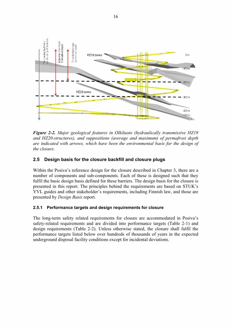
2.4 Environmental basis Posiva’s reference closure concept is based on the established geological and hydrogeological features of the Olkiluoto site, as well as expected average permafrost depth in the case of future very cold and dry periods and the expected geochemical behaviour at different times (e.g. penetration of diluted waters due to the postglacial rebound). Figure 2-2 illustrates ONKALO, major hydraulically conductive geological structures, the average and the maximum permafrost depth as well as the trend of changes in hydraulic conductivity. These features form the environmental basis for the reference design for the closure presented in Chapter 3. The geological, hydrogeological features of the site, as well as the groundwater chemistry as background of the closure design are presented by Dixon et al. (2012). Also the alternatives to the reference closure concept are examined in that background report.
16
Figure 2-2. Major geological features in Olkiluoto (hydraulically transmissive HZ19 and HZ20-structures), and suppositions (average and maximum) of permafrost depth are indicated with arrows, which have been the environmental basis for the design of the closure.
2.5 Design basis for the closure backfill and closure plugs Within the Posiva’s reference design for the closure described in Chapter 3, there are a number of components and sub-components. Each of these is designed such that they fulfil the basic design basis defined for these barriers. The design basis for the closure is presented in this report. The principles behind the requirements are based on STUK’s YVL guides and other stakeholder’s requirements, including Finnish law, and those are presented by Design Basis report. 2.5.1 Performance targets and design requirements for closure The long-term safety related requirements for closure are accommodated in Posiva’s safety-related requirements and are divided into performance targets (Table 2-1) and design requirements (Table 2-2). Unless otherwise stated, the closure shall fulfil the performance targets listed below over hundreds of thousands of years in the expected underground disposal facility conditions except for incidental deviations.

17
Table 2-1. Performance targets identified for closure (Design Basis).
Performance targets
Unless otherwise stated, the closure materials and structures shall fulfill the performance targets listed below over hundreds of thousands of years in the expected repository conditions except for incidental deviations.
Closure shall complete the isolation of the spent nuclear fuel by reducing the likelihood of unintentional human intrusion through the closed volumes.
Closure shall restore the favorable, natural conditions of the bedrock as well as possible.
Closure shall prevent the formation of preferential flow paths and transport routes between the ground surface and deposition tunnels/deposition holes.
Closure shall not endanger the favorable conditions for the other parts of the EBS and the host rock.
Retrieval of the spent nuclear fuel canisters shall be technically feasible in spite of repository tunnel and closure structures.
Table 2-2. Design requirements identified for closure (Design Basis).
Design requirements
The ground surface of the disposal area shall be landscaped to resemble its natural surroundings.
Structures and materials that considerably obstruct unintentional intrusion shall be utilized in the closure of the uppermost parts of the facility and investigation holes extending to the ground surface.
Structures and materials of the closure components shall be selected in such a way that the isolation functions of closure can be provided despite possible loadings related to glacial cycles, such as permafrost or changing groundwater chemical conditions.
Rock materials shall be used increasingly as backfill when moving from the disposal depth up to the ground surface due to the increasing risk of clay erosion.
Closure as a whole shall be so designed that the hydraulic connections from the disposal depth to the surface environment through the closed tunnels, shafts, and investigation holes are not better than through existing natural fractures and fracture zones.
Sections in the underground openings intersected by highly transmissive zones such as the HZ20 structure shall be hydraulically isolated from other facility sections.
The closure as a whole shall be so designed that short-cuts from the deposition tunnels/deposition holes to existing significant groundwater flowpaths are prevented.
The closure components shall keep the backfill and plugs of the deposition tunnels in place.
The amount of chemical species harmful for canister/buffer/deposition tunnel backfill/host rock in closure components shall be limited.
18
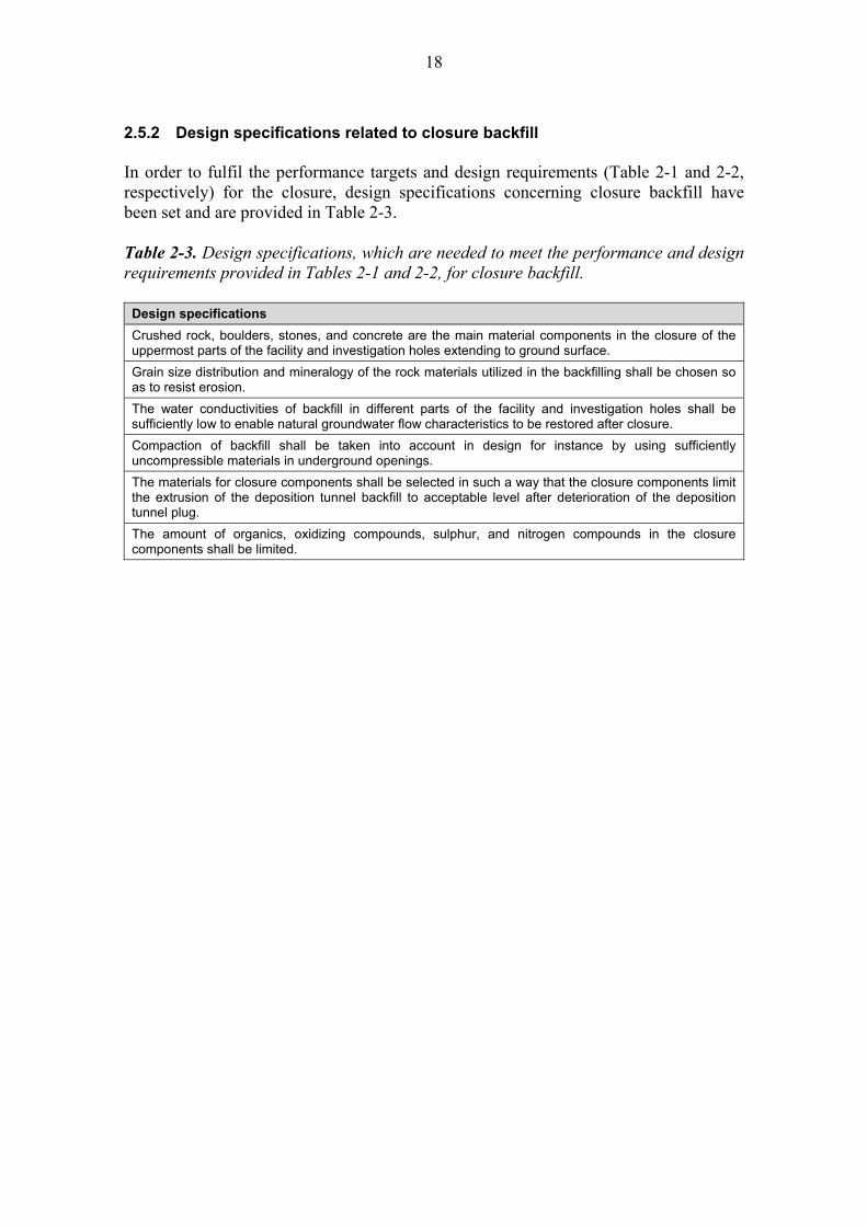
2.5.2 Design specifications related to closure backfill In order to fulfil the performance targets and design requirements (Table 2-1 and 2-2, respectively) for the closure, design specifications concerning closure backfill have been set and are provided in Table 2-3. Table 2-3. Design specifications, which are needed to meet the performance and design requirements provided in Tables 2-1 and 2-2, for closure backfill.
Design specifications
Crushed rock, boulders, stones, and concrete are the main material components in the closure of the uppermost parts of the facility and investigation holes extending to ground surface.
Grain size distribution and mineralogy of the rock materials utilized in the backfilling shall be chosen so as to resist erosion.
The water conductivities of backfill in different parts of the facility and investigation holes shall be sufficiently low to enable natural groundwater flow characteristics to be restored after closure.
Compaction of backfill shall be taken into account in design for instance by using sufficiently uncompressible materials in underground openings.
The materials for closure components shall be selected in such a way that the closure components limit the extrusion of the deposition tunnel backfill to acceptable level after deterioration of the deposition tunnel plug.
The amount of organics, oxidizing compounds, sulphur, and nitrogen compounds in the closure components shall be limited.

19
2.5.3 Design specifications related to the closure plugs Closure plugs (composed of concrete and/or other materials) that will need to be installed to achieve effective closure of the underground disposal facility are associated with the backfill. In order to fulfil the performance targets (Table 2-1) and design requirements (Table 2-2) for the closure, design specifications concerning closure plugs have been set and are provided in Table 2-4. Table 2-4. Design specifications, which are needed to meet the performance and design requirements provided in Tables 2-1 and 2-2, for closure plugs.
Design specifications
Crushed rock, boulders, stones, and concrete are the main material components in the closure of the uppermost parts of the facility and investigation holes extending to ground surface.
Glacial erosion shall be taken into account in the design of the intrusion obstructing structures and materials.
Hydraulic plugs are utilized in the hydraulic isolation of the highly transmissive zones.
Hydraulic isolation of the hydraulic plugs is mainly based on swelling clay materials.
Design specifications of the concrete parts of the plugs shall be defined once the locations of the plugs are known and the loads from adjacent backfill and host rock environment can be determined.
The materials for closure components shall be selected in such a way that the closure components limit the extrusion of the deposition tunnel backfill to acceptable level after deterioration of the deposition tunnel plug.
The amount of organics, oxidizing compounds, sulphur, and nitrogen compounds in the closure components shall be limited.
Low pH concrete mix is used in the closure components composed of concrete and located below HZ20.

20
2.6 Other considerations Development of Posiva’s reference design for closure backfill and plugs is based on the need to accomplish the following:
The closure backfill components shall: Fulfil the requirements set for closure. This means that changes in the composition
of closure materials will occur with depth and local needs. This flexible approach to material composition is referred to as a toolbox-type approach.
Take into account the information developed as background and alternatives evaluated in Dixon et al. (2012).
Be developed and described so that the initial state of all components of the closure with regard to the theoretical minimum, maximum and average states can be defined.
The plugs used as part of the closure shall: Fulfil the requirements set for plugs. Meet the requirements defined for the reference design. This implies that plugs will
vary in terms of their specific design and function based on their location within the underground disposal facility.
Be designed so that concrete type, other materials and the structure itself may vary as a result of the conditions and requirements at the specific plug location. Concrete plugs therefore need to be defined in general terms, allowing a location-specific technical design.
The closure approach has taken influences from the design basis of other production lines. These influences are such as: Plug locations should be situated in rock sections with sparse fractures and
adequate strength properties (plug locations to be indicated and produced in Underground Openings Production Line report).
Excavation tolerances in central tunnels should be set in order to ensure that closure requirements are achievable (excavation according to the tolerances to be produced in Underground Openings Production Line report).
Targets for groundwater inflow into the forthcoming facilities that do not belong to ONKALO construction stage (to be determined in later design stages in Underground Openings Production Line report to ensure that closure requirements are achievable).
The other targets that have guided the design of the closure and its production are: Optimisation of the design with regard to the long term safety, occupational safety,
and feasibility. It may be necessary to simultaneously produce and operate excavation, backfilling of deposition tunnels etc. while one region of the underground disposal facility is undergoing partial closure (e.g. closing of a central tunnel)
Addition to the long-term safety related requirements developed by Posiva, from the production point of view, the closure needs to occur in a manner that ensures that it does not contradict any Finnish laws (e.g. occupational safety or environmental protection).

21
3 REFERENCE DESIGN 3.1 General The reference design for closure of the disposal facility is divided into compartments according to the depth, the location of the opening to be closed as well as prevailing environmental characteristics of bedrock and groundwater and the expected phenomena at different times. Characterisation of a wide range of materials has allowed several potentially viable approaches to backfill related issues for the closure of an underground disposal facility. Many of these could accomplish the performance targets and design requirements identified in Chapter 2. A reference closure design for Posiva’s disposal facility that meets the closure design specifications has been developed. The reference design is based on the studies on the closure alternatives by Dixon et al. (2012) and it is introduced here for the first time. Table 3-1 provides the summary of currently defined, acceptable hydraulic conductivity values for the various backfilling components of the closure system. The values selected are based on the natural hydraulic conductivities of the bedrock (Posiva 2009, Dixon et al. 2012). How materials can be selected that will meet these requirements is discussed in Section 3-6. Acceptable hydraulic conductivities are not defined for any of the plug types. For the closure of investigation boreholes the hydraulic conductivities are as follows: from the surface to the depth of -200 m, maximum allowed hydraulic conductivity for borehole backfill is 10-7 m/s, between the depth of -200 m down to hydraulically conductive zone HZ20 it is 10-8 m/s, and below the zone it is 10-9 m/s. Table 3-1. Summary of hydraulic conductivity values defined for closure backfills. Values are based on rock characterisation results provided in Dixon et al. (2012) and Posiva (2009).
Location to be Installed
Backfill Type Compaction Method
Hydraulic Conductivity
Required (K) (m/s)
Surface above -50 m Boulders -
Above -200 m Crushed Rock In situ ~ 10-7
-200 m to HZ20 Clay-Crushed Rock mix In situ ~ 10-8
HZ20 Plugs and Crushed rock In situ, and
clay blocks and pellets ~ 10-6
HZ20 to -420 m Clay-Crushed Rock mix In situ ~ 10-8
Technical Rooms and Lower Shafts
Crushed Rock In situ ~ 10-7
Central tunnels and vehicle connections
Clay Blocks and Pellets Block and Pellet
installed in the tunnels ~ 10-9

22
3.2 Reference design of the closure backfill in the facilities ≤ 420 metres Posiva, SKB and other organisations have established in their work that there are numerous potentially viable approaches that can be taken in the closure of the central tunnels of an underground disposal facility. Posiva has examined several options and a reference design has been selected for use as a preferred option in backfilling the central tunnels and vehicle connections of a disposal facility located at the Olkiluoto site (Figure 3-1). These volumes are to be filled with similar backfill throughout (Friedland clay in form of 100 % clay blocks and pellets/granules produced from high-smectite-content bentonite) as defined for Posiva’s reference design for deposition tunnel backfill (Backfill Production Line report). Other options for filling these regions are available if for any reason the currently selected reference design proves inadequate or impractical. Examples of these options are described in Dixon et al. (2012).

23
F
igu
re 3
-1.
Ref
eren
ce d
esig
n fo
r cl
osur
e of
cen
tral
tun
nels
, ce
ntra
l tu
nnel
con
nect
ions
and
veh
icle
con
nect
ions
bet
wee
n te
chni
cal
room
s an
d th
e ce
ntra
l tu
nnel
s. P
aral
lel
cent
ral
tunn
els
are
conn
ecte
d to
eac
h ot
her
by c
entr
al t
unne
l co
nnec
tion
s. T
he n
umbe
r an
d lo
cati
ons
of
plug
s ar
e su
gges
tive
.

24
The reference design for the central tunnels and central tunnel connections is the use of block and pellet backfill (Figure 3-2), installed in a manner similar to that used in the smaller deposition tunnels (Backfill Production Line report). The function of this backfill differs from that of the deposition tunnel. The backfill in central tunnels is not required to restrain the swelling of buffer installed in the deposition holes and thus it is not required to have a substantial swelling capacity (swelling pressure). It does however have requirements (see Chapter 2) that will require the use of uncompressible or swelling backfill (e.g. to prevent formation of preferential flow paths and limit the extrusion of deposition tunnel backfill after deterioration of the deposition tunnel end plug). To fulfil the requirement to restore the natural rock conditions, the target water conductivity of the installed backfill is order of 10-9 m/s.
Figure 3-2. Examples of the cross section of the closure backfill in the central tunnels. Two common profiles are presented. Block sizes and assemblies will be designed in greater detail closer to implementation time.
25
Mechanical plugs are used, if needed, to support the installed backfill or to physically isolate one region of the underground disposal facility from another during the operational phase. Hydraulic plugs isolate the central tunnels and vehicle connections from technical rooms and access tunnel. Reference designs for these plugs, together with other details associated are presented in Section 3.7. There are no fixed requirements with respect to the hydraulic conductivity (K) of plugs and so this aspect will need to be assessed with regards to the location and function of each closure-related plug within the disposal facility. 3.3 Reference design of the closure backfill in the technical rooms and
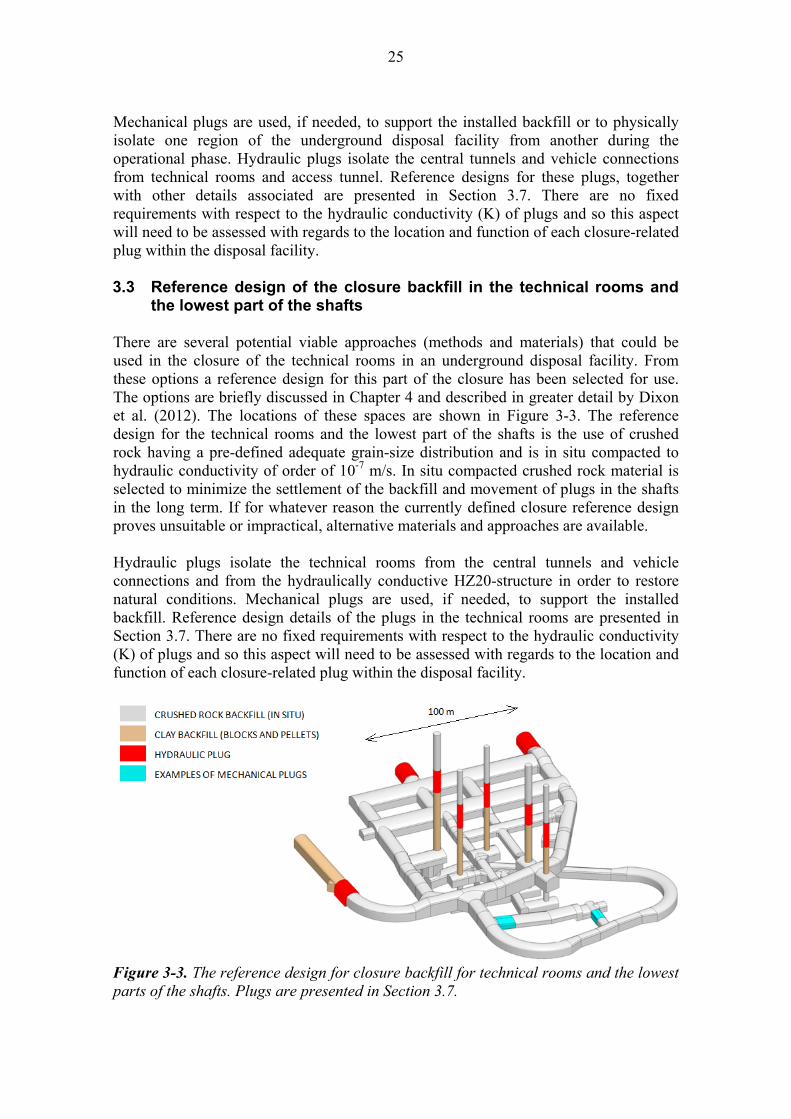
the lowest part of the shafts There are several potential viable approaches (methods and materials) that could be used in the closure of the technical rooms in an underground disposal facility. From these options a reference design for this part of the closure has been selected for use. The options are briefly discussed in Chapter 4 and described in greater detail by Dixon et al. (2012). The locations of these spaces are shown in Figure 3-3. The reference design for the technical rooms and the lowest part of the shafts is the use of crushed rock having a pre-defined adequate grain-size distribution and is in situ compacted to hydraulic conductivity of order of 10-7 m/s. In situ compacted crushed rock material is selected to minimize the settlement of the backfill and movement of plugs in the shafts in the long term. If for whatever reason the currently defined closure reference design proves unsuitable or impractical, alternative materials and approaches are available. Hydraulic plugs isolate the technical rooms from the central tunnels and vehicle connections and from the hydraulically conductive HZ20-structure in order to restore natural conditions. Mechanical plugs are used, if needed, to support the installed backfill. Reference design details of the plugs in the technical rooms are presented in Section 3.7. There are no fixed requirements with respect to the hydraulic conductivity (K) of plugs and so this aspect will need to be assessed with regards to the location and function of each closure-related plug within the disposal facility.
Figure 3-3. The reference design for closure backfill for technical rooms and the lowest parts of the shafts. Plugs are presented in Section 3.7.

26
3.4 Reference design of the closure backfill in the access tunnel Closure backfills defined for the access tunnel may vary depending on local or regional conditions encountered along the corresponding tunnel length as well as changing performance requirements in the volumes they occupy. Major hydraulic conductive fracture zones HZ20 and HZ19 (that divide the bedrock in natural volumes) and average permafrost depth (Figure 2-2) create together one imaginary boundary, which among other factors determines the type of closure backfill. The trend of natural hydraulic conductivity of bedrock is followed in hydraulic conductivity of backfill design and the expected geochemical behaviour is taken into account. A variety of materials, methods and performance characteristics that could be used in backfilling of the access tunnel have been identified. From this information and the site-specific conditions at the Olkiluoto site a reference closure design for these regions has been developed and it is illustrated in Figure 3-4. In order to meet the performance requirements at the various positions set for the shaft and access tunnel backfills, changes in backfill material occur. A flexible toolbox-type approach to material selection and installation allows field-conditions to be taken into account, and thereby use of the best possible option, ensuring that the closure performs as required.
Figure 3-4. Closure backfill for access tunnel and shafts. Plugs are presented in Section 3.7.

27
The principle adopted in this part of the closure is that the closer to the surface the tunnel is backfilled, the more aggregate is used in backfill. This is done in order to match backfill to the natural groundwater flow conditions. Higher hydraulic conductivities than are present in the central tunnels are therefore acceptable and the ability of the backfill to resist erosion due to groundwater flow can be improved by use of a more aggregate-rich material in the near-surface regions. The suggested backfill between the depth level -420 m up to HZ20 (Figure 2-2) is in situ compacted clay-aggregate mixture of which the hydraulic conductivity is order of K ~ 10-8 m/s. Composition of this material is as-yet undefined but it is anticipated that materials having clay-aggregate ratios in the order of 30/70 to 40/60 would be adequate for this purpose. Hydraulically conductive fracture zone HZ20 is isolated from backfilled tunnel with hydraulic plugs and erosion resistant crushed rock backfill (K ~10-6 m/s) in the place of the structure (between the plugs). From HZ20 to the depth level -200 m also in situ compacted clay-aggregate mixture with K ~10-8 m/s is to be used. This backfill material would be of similar composition to that proposed for the region below this feature. Above that depth, including also the repository for low and intermediate level waste, in situ installed crushed rock (K ~10-7 m/s) is suggested. Hydraulically conductive fracture zone HZ19 is isolated from the backfilled tunnel with hydraulic plugs below the zone intersections in the shafts and the access tunnel. Hydraulic plugs isolate the natural bedrock volumes from each other in order to restore natural conditions. There are no fixed requirements with respect to the hydraulic conductivity (K) of plugs and so this aspect will need to be assessed with regards to the location and function of each closure-related plug within the disposal facility. The access tunnel is finally closed with a human intrusion obstructing plug. Additionally, mechanical plugs are used to support the installed backfill, when needed. Reference designs of the plugs with details of how they would be used in the access tunnel are presented in Section 3.7. 3.5 Reference design of the closure backfill in the shafts The fundamental principle for backfill composition design is that the closer to the surface the shaft is backfilled, the higher the amount of aggregate in the backfill. This is done to more closely match the natural hydraulic conditions of bedrock (Dixon et al. 2012). Shaft backfill materials are expected to vary depending on local or regional conditions encountered along their lengths as well as performance requirements in the volumes they occupy. Major hydraulically conductive structures HZ20 and HZ19, which divide the bedrock into natural sub-volumes, and an average permafrost penetration depth create boundaries, which were used to determine the type of closure backfill used in the underground disposal facility. Varieties of materials, methods and performance characteristics that could be used in backfilling of the shafts have been identified and are summarised by Dixon et al. (2012). From this information and the site-specific conditions at the Olkiluoto site a reference closure design for these regions has been developed and is illustrated in Figure 3-4. In order to meet the requirements set for the
28
shaft closure at various elevations, changes in backfill composition are necessary. This requires maintaining of a flexible toolbox type approach to materials selection and installation, thereby providing the best means of ensuring that the system performs as required. Potentially suitable materials are discussed in Section 3.6 and are summarised in Chapter 5. The suggested backfill below the HZ20-zone (between the -420 m level up to the HZ20), is clay backfill installed by block and pellet method (K ~10-9 m/s). This backfill will be placed on a bed of crushed rock in the bottom of the shafts. Hydraulic zone HZ20 is isolated with hydraulic plugs and erosion resistant crushed rock backfill (K ~10-6 m/s) is installed in the region intersected by this structure (between the plugs). Above HZ20 to the depth level -200 m, in situ compressed clay-aggregate mixture with K ~10-8 m/s is to be used as backfill. Above that depth, in situ installed crushed rock (K ~10-7m/s) is suggested. Hydraulic structure HZ19 is isolated from backfilled shafts by hydraulic plugs. The targeted minimum K-values set for backfill are compiled in Table 3-1. Hydraulic plugs isolate the natural bedrock volumes from each other in order to restore natural conditions. The shafts are finally closed with intrusion obstructing plugs. Reference designs for the plugs are presented in Section 3.7. There are no fixed requirements with respect to the hydraulic conductivity (K) of plugs. 3.6 Achieving hydraulic specifications in closure backfill The preceding sections of Chapter 3 describe the various backfilling and sealing components of the closure. This includes, where possible, the target hydraulic conductivities (Table 3-1) to ensure that the closure achieves its design requirements as outlined in Chapter 2. Extensive characterisation of clay materials, aggregate addition, erosive action of inflowing water and groundwater chemistry have been undertaken in the process of developing option for backfill materials in general and this is summarised by Keto et al. (2009) and utilised in developing the generic closure design description provided by Dixon et al. (2012). In order to define backfill formulation options, the development of a toolbox approach where a wide range of materials and placement options can be matched to a pre-determined set of performance properties is appropriate. One such approach that can be utilised in defining options for the backfill materials and design that will require use of swelling clay (e.g. central tunnel backfill, hydraulic plugs) or clay-aggregate mixtures (e.g. access tunnel backfill, shafts) is the parameter known as Effective Montmorillonite Dry Density (EMDD) (Dixon et al. 2011a, b). This parameter allows the equilibrated, saturated hydraulic and swelling pressure properties of backfills to be estimated for a wide range of groundwater environments. The hydraulic properties for regions where clay-rich backfills are designed are based on the natural hydraulic conductivities of bedrock (Posiva 2009, Dixon et al. 2012). The depth-dependent K-values defined for backfill are summarized in Table 3-1. As can be seen by comparing these target hydraulic conductivities to the data provided in Figure 3-5 the required K-values can be readily achieved by smectite-rich clays or clay-

29
aggregate mixtures. It is necessary to consider the groundwater chemistry of each region to be backfilled so as to ensure that performance goals are met. But again use of the normalising parameter Effective Montomorillonite Dry Density (EMDD) provides guidance in that respect (Dixon et al. 2011a, 2012). Based on this, a wide range of clay-crushed rock formulations are possible and these can be adjusted based on the degree of densification that is achievable in the disposal facility backfilling. It should be remembered that EMDD does not provide a measure of erosion resistance during the installation and saturation phase of backfilling and backfill density may need to be adjusted to suit the field environment. For block or in situ compacted materials containing more than 25% swelling clay (Dixon 2000), EMDD allows for quick estimation of system behaviour (swelling pressure and hydraulic conductivity (K), as a part of performance evaluation and material selections. It also allows the evaluation of the effects of field variations in the as-placed backfill and so provides information related to quality control specifications for backfill. Figure 3-5 shows how EMDD allows for normalisation of behavioural data for materials of very different composition (e.g. MX-80-, IBECO- Asha-, Saskatchewan-bentonites or Friedland clay), and for the effects of changing groundwater composition. Detailed discussion is provided in Dixon et al. 2011a and 2012.
Figure 3-5. Generic hydraulic conductivity (K) predicted using EMDD parameter showing effects of groundwater salinity (Dixon et al. 2011a, Fig. 3-3).
1.E-15
1.E-14
1.E-13
1.E-12
1.E-11
1.E-10
1.E-09
1.E-08
1.E-07
1.E-06
1.E-05
0.30 0.50 0.70 0.90 1.10 1.30 1.50 1.70 1.90 2.10
Hyd
rau
lic C
on
du
cti
vit
y (
m/s
)
Effective Montmorillonite Dry Density (Mg/m3)
Deionized water
1 % TDS
3.5 % TDS
7 % TDS
10 - 35 % TDS
Deionized Water
3.5 % TDS7 % TDS
10 - 35 % TDS
30
There is no swelling pressure specification for the closure backfill, but there is a need for it to maintain a contact with its confinement and resist compression by the deposition tunnel backfill after deterioration of the deposition tunnel plugs. This will require at least some capacity to swell, since otherwise there is a potential for time-dependent settlement of the backfill, which would result in a gap at the roof the openings and development of a flow path. The EMDD parameter can be used in selecting materials and densities that can meet these requirements (Dixon et al. 2011a). Swelling pressure differences between adjacent materials will also determine which components expand and which compress as the system saturates. From this it is possible to estimate the system behaviour once saturation is achieved and density equilibration occurs. Crushed rock backfills are typically less problematic with regards to their requirements on hydraulic properties. Reasonable estimates can be developed from conventional civil engineering experiences (i.e. road embankments, dikes, tunnel backfilling in mining) for aggregate-only fills and experiments completed as part of concept development (e.g. Gunnarsson et al. 1996; 2001, Pusch 2008). The K-value of such material depends on the grain size distribution, which can be formulated optimal for any purpose as shown in Table 3-2. Pusch (2008) reviewed options for use of rock-only backfill for its potential for use in the SKB underground disposal facility. This review included conventionally crushed rock as well as muck materials generated by tunnel boring machines (TBM) and related the results of two major experiments at Äspö (the Prototype Repository and the Backfill and Plug Test). The hydraulic conductivity requirements of the regions of Posiva’s underground disposal facility, where rock fill is being considered, ranges from 10-6 to 10-7 m/s (Table 3-1), and so crushed rock materials are suitable for use. Depending on the volume to be backfilled and its geometry there is a variety of options with respect to this type of backfilling and a wide range of hydraulic conductivities that can be achieved. A crushed rock material having a limited (and coarse) size range will have lower compacted density and higher hydraulic conductivity than material sourced as a well-graded aggregate (10-5 to 10-7 m/s), Pusch (2008 p. 32). Crushed rock with a considerable fines (silt-sized) content (e.g. Tunnel Boring Machine (TBM) -muck, or a high fines content materials separated from drill and blast excavated rubble) will exhibit a substantially lower hydraulic conductivity than simple crushed rock fill. Compacted TBM muck can be densified to 2,210-2,430 kg/m3 and at 2,300 kg/m3 the hydraulic conductivity is in the order of 2 x 10⁻¹⁰ m/s. The same material compacted to only 2,100-2,210 kg/m3 had hydraulic conductivity in the range of 2 x 10⁻⁸ to 10-7 m/s (Pusch 2008 p. 23, p. 33). The variety of K-values obtainable with rock based materials are compiled in Table 3-2.
31
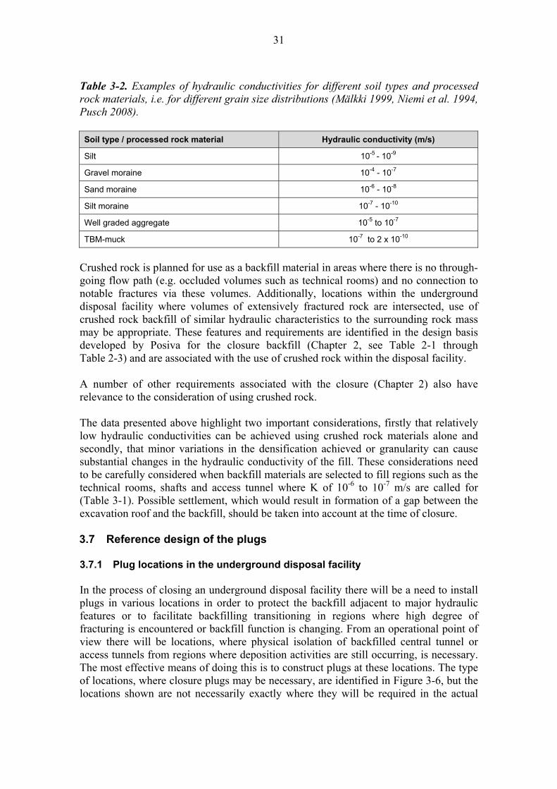
Table 3-2. Examples of hydraulic conductivities for different soil types and processed rock materials, i.e. for different grain size distributions (Mälkki 1999, Niemi et al. 1994, Pusch 2008). Soil type / processed rock material Hydraulic conductivity (m/s)
Silt 10-5 - 10-9
Gravel moraine 10-4 - 10-7
Sand moraine 10-6 - 10-8
Silt moraine 10-7 - 10-10
Well graded aggregate 10-5 to 10-7
TBM-muck 10-7 to 2 x 10⁻¹⁰
Crushed rock is planned for use as a backfill material in areas where there is no through-going flow path (e.g. occluded volumes such as technical rooms) and no connection to notable fractures via these volumes. Additionally, locations within the underground disposal facility where volumes of extensively fractured rock are intersected, use of crushed rock backfill of similar hydraulic characteristics to the surrounding rock mass may be appropriate. These features and requirements are identified in the design basis developed by Posiva for the closure backfill (Chapter 2, see Table 2-1 through Table 2-3) and are associated with the use of crushed rock within the disposal facility. A number of other requirements associated with the closure (Chapter 2) also have relevance to the consideration of using crushed rock. The data presented above highlight two important considerations, firstly that relatively low hydraulic conductivities can be achieved using crushed rock materials alone and secondly, that minor variations in the densification achieved or granularity can cause substantial changes in the hydraulic conductivity of the fill. These considerations need to be carefully considered when backfill materials are selected to fill regions such as the technical rooms, shafts and access tunnel where K of 10-6 to 10-7 m/s are called for (Table 3-1). Possible settlement, which would result in formation of a gap between the excavation roof and the backfill, should be taken into account at the time of closure. 3.7 Reference design of the plugs 3.7.1 Plug locations in the underground disposal facility In the process of closing an underground disposal facility there will be a need to install plugs in various locations in order to protect the backfill adjacent to major hydraulic features or to facilitate backfilling transitioning in regions where high degree of fracturing is encountered or backfill function is changing. From an operational point of view there will be locations, where physical isolation of backfilled central tunnel or access tunnels from regions where deposition activities are still occurring, is necessary. The most effective means of doing this is to construct plugs at these locations. The type of locations, where closure plugs may be necessary, are identified in Figure 3-6, but the locations shown are not necessarily exactly where they will be required in the actual

32
site. Field confirmation of their necessity and exact location will need to be made at the time of closure installation. The vertical shafts will be backfilled and at key locations along them it may be necessary to install plugs to reduce the potential for these vertical excavations from becoming preferential pathways. Generic conceptual design studies have been undertaken to examine options for different plug designs and performance evaluations for locations where there is substantial water inflow (Dixon et al. 2009) and plugs have been installed in a number of field studies related to underground disposal facility sealing (e.g. Backfill and Plug Test (Gunnarsson et al. 2002), Prototype Repository (Johannesson et al. 2004, Dahlström 2009), Tunnel Sealing Experiment (Martino et al. 2008), Enhanced Sealing Project (Martino et al. 2011). As with the other components of the closure, the designs of these plugs are not rigidly fixed and will be adjusted as necessary in order that they fulfil their role in underground disposal facility closure and work in a complimentary manner with adjacent closure components. Each plug should be designed for installation in a location specifically selected for it.

33
F
igu
re 3
-6. A
ppro
xim
ate
num
ber
and
loca
tion
s of
clo
sure
-rel
ated
plu
gs in
the
unde
rgro
und
disp
osal
faci
lity
.
34
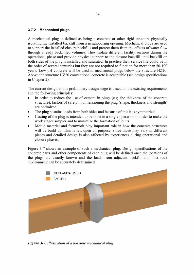
3.7.2 Mechanical plugs A mechanical plug is defined as being a concrete or other rigid structure physically isolating the installed backfill from a neighbouring opening. Mechanical plugs are used to support the installed closure backfills and protect them from the effects of water flow through already backfilled volumes. They isolate different facility sections during the operational phase and provide physical support to the closure backfill until backfill on both sides of the plug is installed and saturated. In practice their service life could be in the order of several centuries but they are not required to function for more than 50-100 years. Low pH concrete will be used in mechanical plugs below the structure HZ20. Above the structure HZ20 conventional concrete is acceptable (see design specifications in Chapter 2). The current design at this preliminary design stage is based on the existing requirements and the following principles: In order to reduce the use of cement in plugs (e.g. the thickness of the concrete
structure), factors of safety in dimensioning the plug (shape, thickness and strength) are optimized.
The plug sustains loads from both sides and because of this it is symmetrical. Casting of the plug is intended to be done in a single operation in order to make the
work stages simpler and to minimize the formation of joints. Mould material and formwork play important role in how the concrete structures
will be build up. This is left open on purpose, since those may vary in different places and detailed design is also affected by experiences during operational and closure phases.
Figure 3-7 shows an example of such a mechanical plug. Design specifications of the concrete parts and other components of each plug will be defined once the locations of the plugs are exactly known and the loads from adjacent backfill and host rock environment can be accurately determined.
Figure 3-7. Illustration of a possible mechanical plug.
35
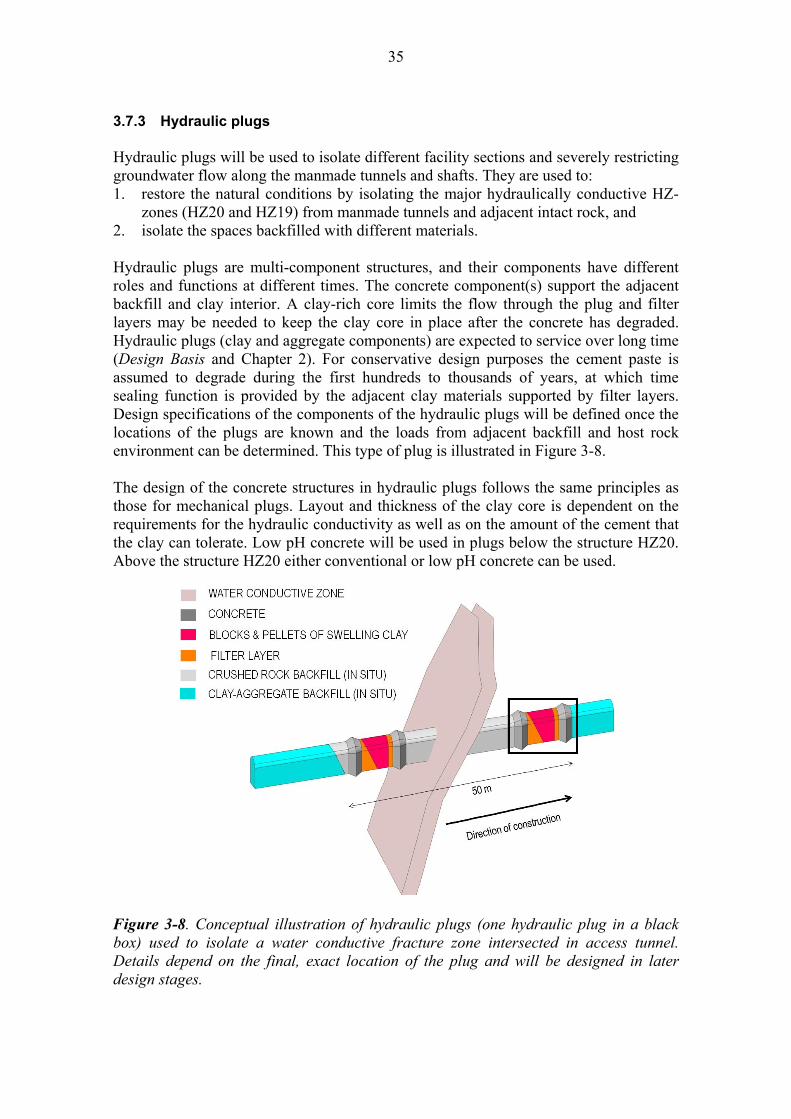
3.7.3 Hydraulic plugs Hydraulic plugs will be used to isolate different facility sections and severely restricting groundwater flow along the manmade tunnels and shafts. They are used to: 1. restore the natural conditions by isolating the major hydraulically conductive HZ-
zones (HZ20 and HZ19) from manmade tunnels and adjacent intact rock, and 2. isolate the spaces backfilled with different materials. Hydraulic plugs are multi-component structures, and their components have different roles and functions at different times. The concrete component(s) support the adjacent backfill and clay interior. A clay-rich core limits the flow through the plug and filter layers may be needed to keep the clay core in place after the concrete has degraded. Hydraulic plugs (clay and aggregate components) are expected to service over long time (Design Basis and Chapter 2). For conservative design purposes the cement paste is assumed to degrade during the first hundreds to thousands of years, at which time sealing function is provided by the adjacent clay materials supported by filter layers. Design specifications of the components of the hydraulic plugs will be defined once the locations of the plugs are known and the loads from adjacent backfill and host rock environment can be determined. This type of plug is illustrated in Figure 3-8. The design of the concrete structures in hydraulic plugs follows the same principles as those for mechanical plugs. Layout and thickness of the clay core is dependent on the requirements for the hydraulic conductivity as well as on the amount of the cement that the clay can tolerate. Low pH concrete will be used in plugs below the structure HZ20. Above the structure HZ20 either conventional or low pH concrete can be used.
Figure 3-8. Conceptual illustration of hydraulic plugs (one hydraulic plug in a black box) used to isolate a water conductive fracture zone intersected in access tunnel. Details depend on the final, exact location of the plug and will be designed in later design stages.

36
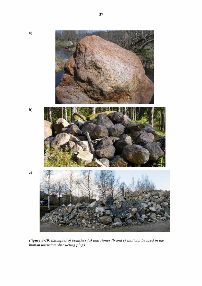
3.7.4 Intrusion obstructing plugs Plugs to obstruct inadvertent human intrusion to the facility will be used in the uppermost parts (vertical depth 25-30 m) of the underground disposal facility, i.e. in the mouth of the access tunnel and the shafts. These human intrusion obstructing plugs are multi-component structures, and each of their components has different roles and functions at different times. Human intrusion obstructing plugs shall function over long term. This type of a plug is illustrated in Figure 3-9. Intrusion obstructing plugs consist of big boulders and filter layers, followed by rigid concrete structures and natural stones and/or boulders in the uppermost part of the plug (examples shown in Figure 3-10). These boulders are intended to hamper human intrusion by being cumbersome to move and/or drill, and concrete structures both hamper reaching the underlying boulder-filled section and provide a base on which naturally-occurring landscaping boulders rest.
Figure 3-9. Conceptual illustration of an intrusion obstructing plug in the access tunnel. Details will be designed in later design stages. Figure is tilted for better visualization and the entrance (ground surface) is on the right.
37
a)
b)
c)
Figure 3-10. Examples of boulders (a) and stones (b and c) that can be used in the human intrusion obstructing plugs.

38
3.7.5 The reference design of the concrete mixes of the closure plugs Low pH concrete is intended to be used below the hydraulically conductive structure HZ20 (see Chapter 2). Vogt et al. (2009) have developed and tested one potential recipe for low pH concrete for the plugs. This recipe is given in the Table 3-3 below. Note that changes both to the components (trademarks) and/or the proportioning of the components are expected in future. There are also alternative recipes for low pH concretes. A potential concrete mix for the plugs above the hydraulically conductive fracture zone HZ20 is presented in Table 3-4. This is a potential standard, good quality concrete mix for plugs to be located in conditions prevailing between the depth range from 0 to 300 m. However, there is presently no identified reason why low pH concrete could not be used above HZ20 as well. Table 3-3. A reference low pH concrete mix for closure plugs below the hydraulically conductive fracture zone HZ20 (Vogt et al. 2009).
Design parameter Material Composition (kg/m3)
Binder Cement CEM I 42.5 MH/LA/SR 120
Densified Silica fume 80
Water Tap water 165
Filler Limestone filler L25 369
Sand 0-8 mm 1,037
Gravel 8-16 mm 558
Admixture Superplasticizer Glenium 51 6.38
Table 3-4. A reference concrete mix for closure plugs above the hydraulically conductive fracture zone HZ20. Design parameter Material Composition (kg/m3)
Binder Cement CEM II/A-LL 42.5 SR 313.9
Densified Silica fume 34.5
Water Tap water 122
Filler Sand 0-8 mm 1,010.5
Gravel 8-16 mm 821.5
Admixture Superplasticizer (naftalene sulphonate based, Mighty 150 or similar)
To be designed later
39
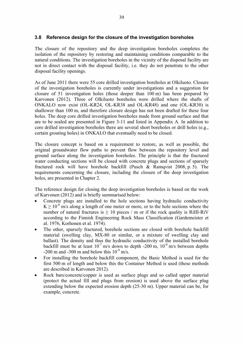
3.8 Reference design for the closure of the investigation boreholes The closure of the repository and the deep investigation boreholes completes the isolation of the repository by restoring and maintaining conditions comparable to the natural conditions. The investigation boreholes in the vicinity of the disposal facility are not in direct contact with the disposal facility, i.e. they do not penetrate to the other disposal facility openings. As of June 2011 there were 55 core drilled investigation boreholes at Olkiluoto. Closure of the investigation boreholes is currently under investigations and a suggestion for closure of 51 investigation holes (those deeper than 100 m) has been prepared by Karvonen (2012). Three of Olkiluoto boreholes were drilled where the shafts of ONKALO now exist (OL-KR24, OL-KR38 and OL-KR48) and one (OL-KR30) is shallower than 100 m, and therefore closure design has not been drafted for these four holes. The deep core drilled investigation boreholes made from ground surface and that are to be sealed are presented in Figure 3-11 and listed in Appendix A. In addition to core drilled investigation boreholes there are several short boreholes or drill holes (e.g., certain grouting holes) in ONKALO that eventually need to be closed. The closure concept is based on a requirement to restore, as well as possible, the original groundwater flow paths to prevent flow between the repository level and ground surface along the investigation boreholes. The principle is that the fractured water conducting sections will be closed with concrete plugs and sections of sparsely fractured rock will have borehole backfill (Pusch & Ramqvist 2008, p. 5). The requirements concerning the closure, including the closure of the deep investigation holes, are presented in Chapter 2. The reference design for closing the deep investigation boreholes is based on the work of Karvonen (2012) and is briefly summarised below: Concrete plugs are installed to the hole sections having hydraulic conductivity
K ≥ 10-8 m/s along a length of one meter or more, or to the hole sections where the number of natural fractures is ≥ 10 pieces / m or if the rock quality is RiIII-RiV according to the Finnish Engineering Rock Mass Classification (Gardemeister et al. 1976, Korhonen et al. 1974).
The other, sparsely fractured, borehole sections are closed with borehole backfill material (swelling clay, MX-80 or similar, or a mixture of swelling clay and ballast). The density and thus the hydraulic conductivity of the installed borehole backfill must be at least 10-7 m/s down to depth -200 m, 10-8 m/s between depths -200 m and -300 m and below this 10-9 m/s.
For installing the borehole backfill component, the Basic Method is used for the first 500 m of length and below this the Container Method is used (these methods are described in Karvonen 2012).
Rock bars/concrete/copper is used as surface plugs and so called upper material (protect the actual fill and plugs from erosion) is used above the surface plug extending below the expected erosion depth (25-30 m). Upper material can be, for example, concrete.

40
The reference design for the closure of the deep investigation boreholes is reasoned as follows: The hydraulic conductivities of closure materials follow those of bedrock in order
to restore natural conditions. Tight borehole backfill material retards water flow along the investigation holes
and thus minimizes the changes in natural groundwater conditions. Concrete plugs to be cast in fractured / water conductive sections withstand erosion
better than clay, and after the cementitious component is fully degraded the aggregate component remains.
In the far future the cementitious component of the borehole plugs is expected to be leached out of the concrete. The overall sealing function will be retained due to the ballast grain framework, which remains in the hole, to support the sections with borehole backfill (Pusch & Ramqvist 2008, p. 41). Based on current knowledge, the best methods for placing the borehole backfill are the Basic Method and the Container Method. In the Basic Method, a perforated copper tube will be filled with dense borehole backfill material that will, when affected by groundwater, extrude through the tube holes into an investigation hole (Pusch & Ramqvist 2008, p. 8). In the Container Method dense cylindrical borehole backfill blocks will be transported down an investigation hole in a water tight container and extruded in desired depth (Pusch & Ramqvist 2008, p. 19-20). In the Basic Method the tube and borehole backfill will remain in the investigation hole and in the Container Method borehole backfill and a bottom plate, probably consisting of copper, will remain in the investigation hole. In the Basic Method, when the tube is pushed downwards, water in the investigation hole erodes borehole backfill material through the perforated holes of the tube. Salinity in the water increases the migration of swelling clay and resistance to installation and therefore the water should be replaced with fresh water beforehand (Pusch & Ramqvist 2008, p. 17). The Container Method could be a better alternative for borehole backfill placement as the swelling clay is not exposed to water until in desired depth, but the method is still under development and large scale field tests have not yet been performed (Pusch & Ramqvist 2008, p. 19-25). The Basic Method was successfully demonstrated in closing OL-KR24 (Rautio 2006). One parameter to present how the hydraulic requirements of the clay-filled portions of the borehole backfill are met is the effective montmorillonite dry density (EMDD), described previously in Section 3.6. EMDD takes into account differences in groundwater salinity and provides an estimate of the hydraulic conductivity (Figure 3-5) and swelling pressure (Dixon et al. 2011a) of the swelling clay once swelling and density equilibration is achieved. In addition to preventing water flow, the swelling clay must swell adequately to fill the investigation holes. In the Basic Method it must swell through the perforated holes and with the Container Method it must be able to fill the gap between the container and rock wall and also the void that was occupied by the container when the borehole backfill was installed.
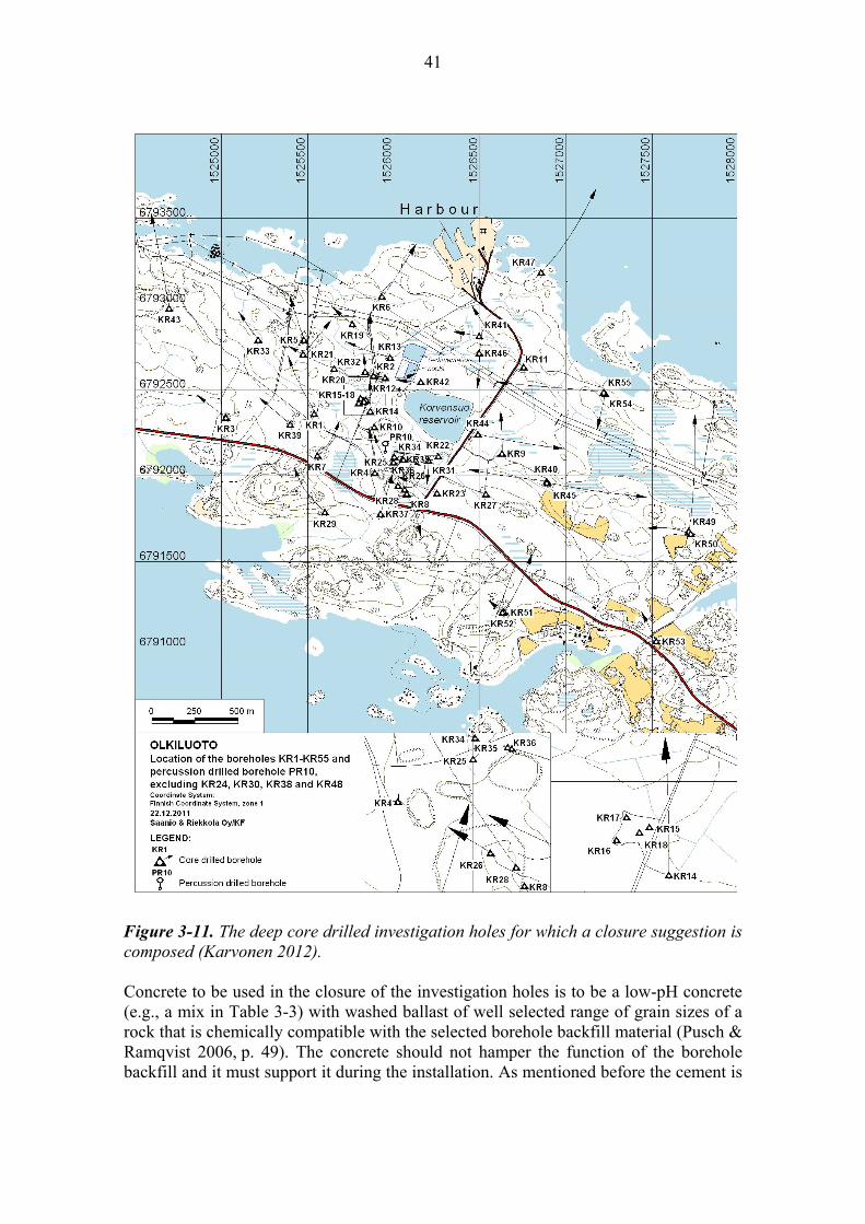
41
Figure 3-11. The deep core drilled investigation holes for which a closure suggestion is composed (Karvonen 2012). Concrete to be used in the closure of the investigation holes is to be a low-pH concrete (e.g., a mix in Table 3-3) with washed ballast of well selected range of grain sizes of a rock that is chemically compatible with the selected borehole backfill material (Pusch & Ramqvist 2006, p. 49). The concrete should not hamper the function of the borehole backfill and it must support it during the installation. As mentioned before the cement is

42
expected to leach slowly out of the concrete plug and the physical grain frame is to remain to support the borehole backfill sections (Pusch & Ramqvist 2006, Appendix V). Surface plugs (correspond to intrusion obstructing plugs in tunnel and shafts) can be manufactured of e.g., copper, concrete or rock (Pusch & Ramqvist 2008, p. 43). Karvonen (2012) suggested solid rock bars. Above surface plugs material such as concrete or rock that protects the fill in the investigation boreholes should be installed. Surface plugs should be below the depth of 25-30 m so that future glaciations do not erode them away. An example of a design for the closure of an investigation hole is illustrated in Figure 3-12.
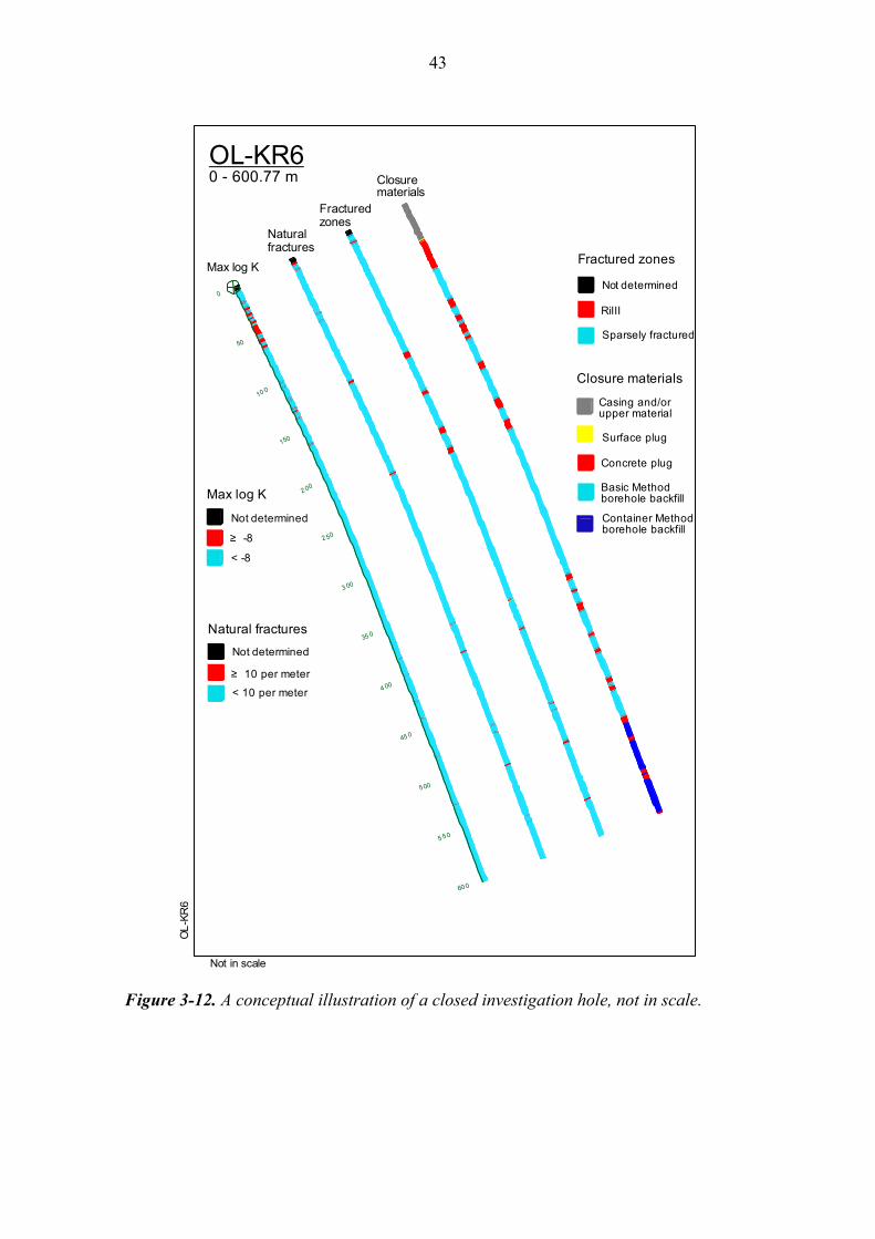
43
60 0
5 5 0
5 00
45 0
4 00
35 0
3 00
2 50
2 00
150
10 0
50
0
Not in scale
OL
-KR
6
OL-KR60 - 600.77 m
≥ 10 per meter
< 10 per meter
Not determined
≥ -8
< -8
Not determined
Max log K
Natural fractures
Fractured zones
Closure materials
Casing and/or upper material
Concrete plug
Basic Method borehole backfill
Max log K
Natural fractures
Fractured zones
Closure materials
Container Methodborehole backfill
Surface plug
RiIII
Sparsely fractured
Not determined
Figure 3-12. A conceptual illustration of a closed investigation hole, not in scale.

44

45
4 PRODUCTION OF THE CLOSURE 4.1 Progress of the closure This section presents an example of the possible step-wise progress of closing the underground disposal facility. The first panel (referred to as the North-East panel in Figure 4-1) is anticipated to be constructed by 2020 when the disposal of the spent fuel will be started. The construction and the final disposal operation of the deposition tunnels proceed step-wise and the backfilling of the central tunnels of one entire panel will follow in a few years after deposition tunnels are closed (Saanio et al. 2012). The closure of the central tunnels in the first panel is presently planned to take place in the period 2074-2098, after the deposition tunnels in the North-East panel are backfilled (Figure 4-1). The closure continues in the South-West panel and the central tunnels in that area will be closed during the years 2080-2098. Finally, the central tunnels of the South-East panel will be closed 2098-2120. The closure of the vehicle connections, technical rooms, access tunnel and shafts will start in approximately 2120. As all of the deposition tunnels in a panel are backfilled and closed, the closing of central tunnels can start. Parallel central tunnels shall be designed and scheduled to be backfilled simultaneously, so that central tunnel connections can serve as emergency exits (according to the prevailing laws and norms). Mechanical plugs are installed when needed (mainly due to the local water inflows). There might also be a need to install mechanical plugs in central tunnel connections. Finally hydraulic plugs are installed in the mouth of central tunnels or in other suitable locations in order to isolate the closed area from the tunnels in operation. The existing infrastructures and equipments will be exploited as much as possible, which means that deposition tunnel backfill activities and closure activities will be designed as compatible as possible. On the other hand, the activities shall be designed so that these possibilities are taken into account. During the years 2071-2120, based on the schedule provided above, the following materials for the closure of the underground disposal facility are needed: Blocks of Friedland clay and pellets of high quality bentonite for backfilling of the
central tunnels (~377 000 m3 and ~28 000 – 105 000 m3, respectively) Foundation bed for central tunnels (~16 000 – 62 000 m3) Concrete and its components for mechanical plugs, if needed. It’s important to note that the largest amounts of pellets and foundation bed materials listed above are related to the needs associated with the maximum degree of tunnel over excavation (volume that exceeds target tunnel dimensions). The closer the profile is to the theoretical, the smaller is the amount of backfill needed and the lower is the cost of backfilling. After the year 2120 closure materials required include: Crushed rock for the technical rooms and the lowest part of the shafts
(~118 000 m3)
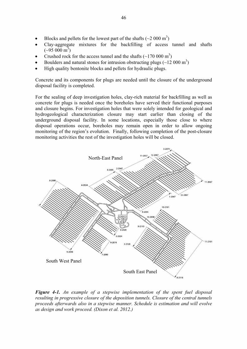
46
Blocks and pellets for the lowest part of the shafts (~2 000 m3) Clay-aggregate mixtures for the backfilling of access tunnel and shafts
(~95 000 m3) Crushed rock for the access tunnel and the shafts (~170 000 m3) Boulders and natural stones for intrusion obstructing plugs (~12 000 m3) High quality bentonite blocks and pellets for hydraulic plugs. Concrete and its components for plugs are needed until the closure of the underground disposal facility is completed. For the sealing of deep investigation holes, clay-rich material for backfilling as well as concrete for plugs is needed once the boreholes have served their functional purposes and closure begins. For investigation holes that were solely intended for geological and hydrogeological characterization closure may start earlier than closing of the underground disposal facility. In some locations, especially those close to where disposal operations occur, boreholes may remain open in order to allow ongoing monitoring of the region’s evolution. Finally, following completion of the post-closure monitoring activities the rest of the investigation holes will be closed.
Figure 4-1. An example of a stepwise implementation of the spent fuel disposal resulting in progressive closure of the deposition tunnels. Closure of the central tunnels proceeds afterwards also in a stepwise manner. Schedule is estimation and will evolve as design and work proceed. (Dixon et al. 2012.)
South West Panel
North-East Panel
South East Panel
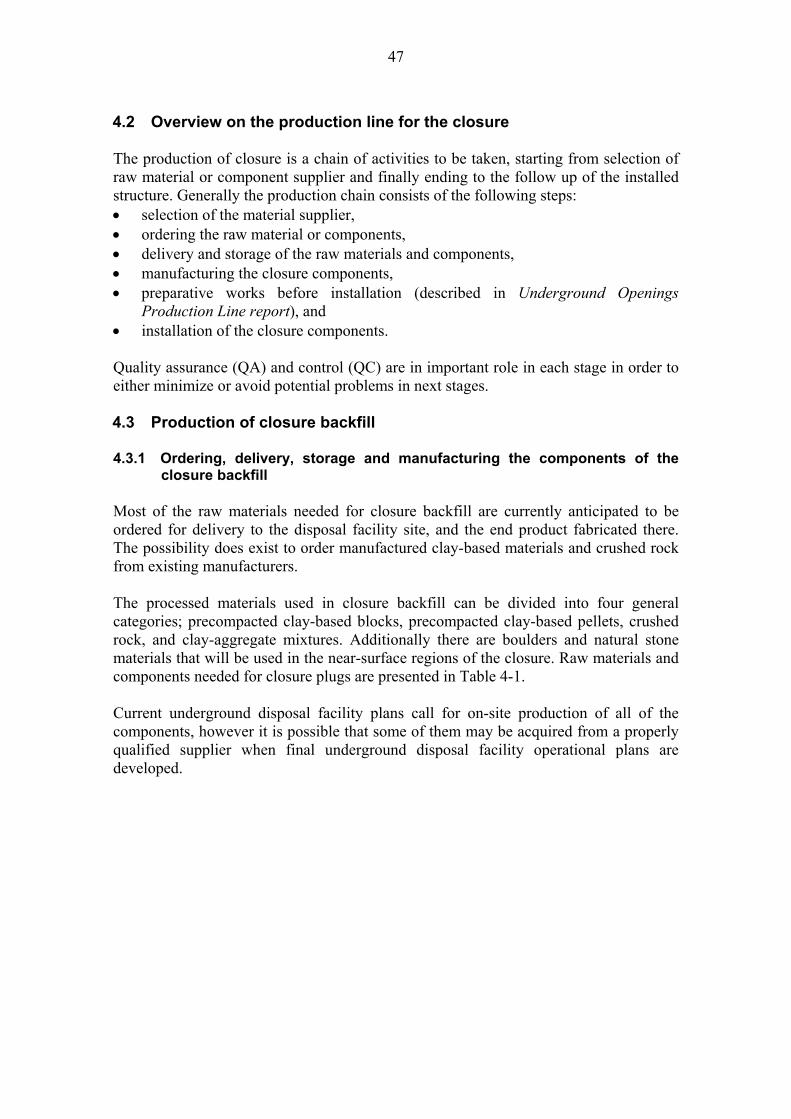
47
4.2 Overview on the production line for the closure The production of closure is a chain of activities to be taken, starting from selection of raw material or component supplier and finally ending to the follow up of the installed structure. Generally the production chain consists of the following steps: selection of the material supplier, ordering the raw material or components, delivery and storage of the raw materials and components, manufacturing the closure components, preparative works before installation (described in Underground Openings
Production Line report), and installation of the closure components. Quality assurance (QA) and control (QC) are in important role in each stage in order to either minimize or avoid potential problems in next stages. 4.3 Production of closure backfill 4.3.1 Ordering, delivery, storage and manufacturing the components of the
closure backfill
Most of the raw materials needed for closure backfill are currently anticipated to be ordered for delivery to the disposal facility site, and the end product fabricated there. The possibility does exist to order manufactured clay-based materials and crushed rock from existing manufacturers. The processed materials used in closure backfill can be divided into four general categories; precompacted clay-based blocks, precompacted clay-based pellets, crushed rock, and clay-aggregate mixtures. Additionally there are boulders and natural stone materials that will be used in the near-surface regions of the closure. Raw materials and components needed for closure plugs are presented in Table 4-1. Current underground disposal facility plans call for on-site production of all of the components, however it is possible that some of them may be acquired from a properly qualified supplier when final underground disposal facility operational plans are developed.

48
Table 4-1. Raw materials and backfill components to be ordered and/or delivered to the site (currently anticipated sourcing marked as X).
Backfill component Raw material / ingredients
Manufacturing of the structure/ prefabricated
component at site
Purchase as prefabricated component
Clay blocks Swelling clay X
Clay pellets Swelling clay Bentonite clay
X
Clay-aggregate mixtures
Swelling clay Aggregate and/or gravel
X
Crushed rock Excavated host rock Locally-sourced crushed rock
X
Backfill blocks The manufacture of clay-based block materials to be used in the closure will be designed to be compatible with the procedures determined for backfill (Backfill Production Line report). Uniaxial compaction method is selected as most appropriate also for closure backfill production purposes. Uniaxial compaction (Pusch 2002, Holt & Peura 2011) is a conventional method for use in manufacturing of dense clay-based blocks (either clay-only or clay-aggregate) at rates rapid enough to make them cost-effective for use in the closure system. Depending on the block composition, size and density required several means of uniaxial compaction have been demonstrated to produce closure blocks. Precompacted Friedland clay blocks with ~30% smectite content have been selected for use in the central tunnels. Friedland clay has been successfully compacted into blocks using the same technology as has been used for manufacturing of blocks from bentonite. The Friedland clay blocks have been demonstrated to be compactable to dry densities of 2,010-2,100 and 2,050 kg/m3 (Johannesson & Nilsson 2006, Table 5-1, Riikonen 2009, p. 61, Table 5-2, respectively). The maximum dry density achievable for clays depends on the specific clay used, water content during compaction and the compaction energy. At present it is assumed that closure blocks will be manufactured in the plant located at the disposal facility site, using appropriately sourced materials and methods. The process is described in detail in Backfill Production Line report. During the compaction process load, volume and quantity of material in each mould are carefully controlled. The controlling has resulted to blocks of highly consistent density and size (Gunnarsson et al. 2007, Hansen et al. 2009). In the reference closure concept, blocks will be manufactured using swelling clay based raw materials. Block manufacturing has been demonstrated and the tests have shown that uniaxial compaction can be used for large numbers of blocks of very high consistency (Koskinen 2012). A storage for closure backfill blocks shall be big enough for a sufficient quantity of the blocks to facilitate routine operations and accommodate periods when block production is interrupted. The storage facility will be designed to provide a constant-temperature

49
and humidity controlled environment that will prevent unacceptable levels of block hydration or desiccation. Pellets for backfill and plug interiors The closure system proposed utilises swelling clay materials to fill small gaps between block-filled regions and the surrounding rock. This serves to protect the blocks and provides some degree of water retention capacity to the tunnel during the period immediately following block installation. Manufacture of pelletised or granulated bentonite is a well-established industrial process and planned to be undertaken at the disposal facility site at the production plant for clay components. The moisture content of the clay products and thus the careful manufacturing quality control including control of the relative humidity of the atmosphere around them are important. Hence a storage room, where atmospheric moisture variation is controlled, is needed. Pellets can be precompacted or extruded. The extrusion method has been selected as a reference method for production reasons (same method for deposition tunnel backfill). Viable alternatives to extruded pellets include crushed natural bentonite and roller-compacted pellets and these are presented by Dixon et al. (2012) as part of the closure concept options review. Production will be done using extrusion equipment, generating the density of the materials higher than naturally. This technology is commonly used to produce animal feed, wood pellets for fuel, and fertiliser. Extruded pellets can be produced as rods of consistent diameter but their length is not always consistent (Figure 4-2). The extruded materials have been tested in large-scale simulations at Äspö as well as in Riihimäki (Dixon et al. 2008a, b, 2011b, Riikonen 2009). They can be placed effectively in relatively narrow spaces using spraying. The pellets themselves can be manufactured to a variety of densities depending on the materials and specific manufacturing technique used. The as-placed density of bentonite pellets is somewhat limited when spraying placement or dry pouring is used (typically 900-1,100 kg/m3) (Wimelius & Pusch 2008, Dixon et al. 2008a, b, 2011b). However, lower density is sufficient as these pellets are only intended to slow initial water movement into and past the block-filled region while in the longer-term they contribute to the average density of the backfill entity by partially filling void space that would otherwise have to be filled by swelling of the backfill blocks. The hydraulic conductivity of pellet materials on their own is very low and can be estimated using the relationship presented in Figure 3-5, but groundwater composition, compressibility and the amount of voids need to be considered.

50
Figure 4-2. Extruded bentonite pellets (Backfill Production Line report). Clay-aggregate mixtures for in situ backfills
Clay-aggregate mixtures can be readily prepared using a wide range of conventional techniques including rotary-drum mixers, paddle mixers and augers. Tests conducted at various laboratories (Korkiala-Tanttu et al. 2007, Dixon & Keto 2008) have demonstrated the relative ease of preparing large quantities of clay-aggregate backfill using these techniques as well as its subsequent transportation, placement and in situ compaction. In a batching production process, preparation is based on dry mass proportioning together with careful metering in of mixing water. This is a straight-forward process commonly used in preparation of concrete or specialty fill materials. As there will likely be at least a few hours between batch preparation and its use, relatively simple quality control methods (e.g. wet washing to confirm clay-aggregate ratio and gravimetric water content analysis) will provide confirmation of batch suitability or identify what remedial treatment will be needed to ensure its suitability. The current plan is for on-site manufacture of the clay-aggregate mixtures. This will allow for minimizing of transport of moisture-conditioned raw materials and the risk of transport-related damage to precompacted materials. The proximity of the excavated rock from the disposal facility site is also desirable, if it is to be used in the manufacture of aggregate-clay materials. The key factors in preparing and storing of these materials are associated with moisture control (constant-humidity conditions) following their mixing as well as the potential for self-compaction of mixed materials, if stored in large masses. These are not technically challenging issues. Therefore simple bulk storage of raw materials, or other as-required handling procedures based on production techniques can be utilised.
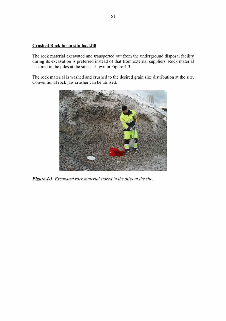
51
Crushed Rock for in situ backfill The rock material excavated and transported out from the underground disposal facility during its excavation is preferred instead of that from external suppliers. Rock material is stored in the piles at the site as shown in Figure 4-3. The rock material is washed and crushed to the desired grain size distribution at the site. Conventional rock jaw crusher can be utilised.
Figure 4-3. Excavated rock material stored in the piles at the site.

52
4.3.2 Installation of the block & pellet backfill Posiva’s selection as its reference method for use in central tunnel closure and the lower portion of the shafts is the block and pellet backfilling technique (Chapter 3). Central Tunnel Backfilling The closure sequencing for the central tunnels is not anticipated to be as rate-sensitive as it is for backfilling operations in the deposition tunnels. The central tunnel backfill does not have to keep buffer in the deposition hole. The sequencing has to be organized so that inconveniences to installation due to possible local inflows can be controlled. In terms of performance, its key properties can therefore be described in terms of its need to be sufficiently incompressible to keep other components (e.g. backfill and plugs) in place, sufficiently low permeability, resistant enough to erosion and capable to carry itself as long as a section is closed with a plug (Tables 2-1 through 2-3). The basic process involved in central tunnel backfill placement involves the following steps after preparing the tunnel for backfilling (e.g. dismantling of the tunnel infra, cleaning, dewatering, and installation of any temporary water collection or diversion structures): 1. Installation of a layer of foundation bed material for a length of tunnel sufficient for
a single backfill installation cycle. The pellet or crushed bentonite or mixture material will be mechanically compacted using conventional techniques and equipment until it reaches the required density and thickness.
2. Installation of precompacted clay blocks on the foundation bed such that they fill the majority of the tunnel volume (>70%). The blocks will be installed tightly and so that a narrow gap between the rock and the blocks along the walls and roof of the tunnel will remain. Fixed backfill block geometry will be utilised to simplify and speed block installation operations, resulting in a variable gap dimension between the blocks and the surrounding rock.
3. Following block installation to fill a suitable length of the tunnel, the gap between the blocks and the surrounding rock mass is to be filled with clay pellets by spraying. This will fill any open voids in the system and completes the backfilling process for that section of the tunnel.
Installation of each of these components requires different technologies to be utilised. The foundation bed material will require machinery capable of: transporting large volumes of clay pellets/granules to the working area, spreading the material into a level mass of appropriate thickness, and adequate compaction of the foundation bed material into a level surface. Depending on the location, roughness of the rock floor and thickness required of the foundation bed material, the place-level-compact process may need to be repeated several times. During this process there will be a need to ensure that any water entering the region is either of small-enough quantity to be unimportant or is diverted/collected so as not to disrupt the compaction process.

53
After the completion of foundation bed material installation, the blocks are installed on it. The block installation has been described by Hansen et al. 2009 and it can be accomplished using conventional technologies (Wimelius & Pusch 2008). The block backfilling rate that could be achieved in a central tunnel is estimated to be 5.5-6 h/m of tunnel length filled (estimated by scaling the deposition tunnel block backfilling rate Hansen et al. 2009). The actual rate of backfilling will be an important consideration when evaluating how long the backfill front can be left open and how well it tolerates inflowing water. It should also be noted that the larger dimensions of these openings may also facilitate use of larger equipment or installation of larger block assemblies, which would increase the rate of backfilling. Following block installation, spraying will be used to place pellet-type materials with addition of water during spraying. This technique has been used extensively in installation of clay, clay-aggregate and clay-pellet materials as part of the block and pellet installations for field-scale experiments (see Figure 4-5) (Martino & Dixon 2007, Martino et al. 2008, Dixon et al. 2011b). It has been used to pre-fill regions where relatively small volumes of fill were needed in order to complete filling of voids e.g. block and pellet backfilling (Dixon et al. 2011b). It can also be used to place relatively fine aggregate-only materials into confined areas where other installation options are impractical (Pusch 2002). In a full-scale tunnel sealing experiment installation of aggregate-clay material could be placed at rates of 100 kg/min (~4.1 m3/h), using a single, man-operated hose, Figure 4-5 (Chandler et al. 2002 p. 93). Wimelius & Pusch (2008, p. 51) also installed pellets into a full-scale mock up of a deposition tunnel using the same technology (Figure 4-6) achieving as-placed densities of ~900 kg/m3, which is comparable to what was accomplished in the ½-scale tests shown in Figure 4-5 (Dixon et al. 2008a, b, 2011b).

54
Spraying aggregate and aggregate-clay to fill crown regions of a tunnel simulation
Installation of clay onto walls of underground tunnel
Clay-block assembly prior to pellet installation
Installing clay pellets showing spray nozzle
(foreground)
Completed block pellet assembly
Figure 4-5. Installation of pellet material using spraying for clay, clay-aggregate or aggregate-only materials (Upper left Martino & Dixon 2007, Fig. 15; Upper right Martino et al. 2008, Fig. 2.46; Lower photos from Dixon et al. 2011b, Fig. 2-3).
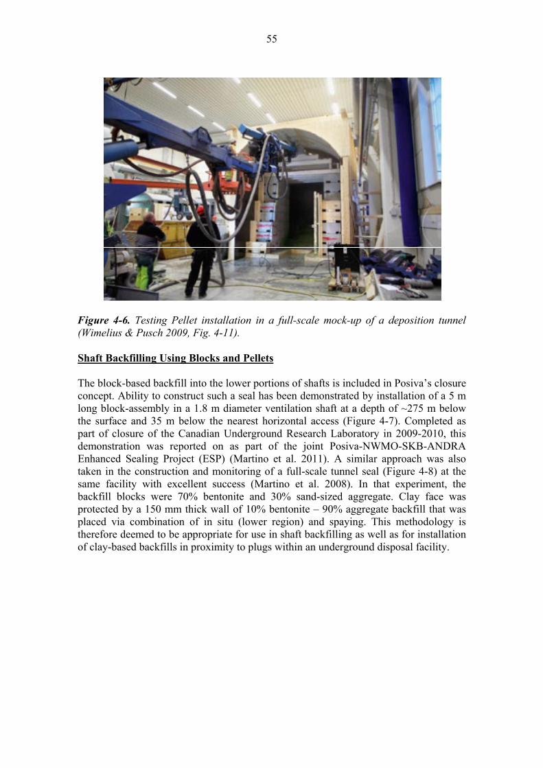
55
Figure 4-6. Testing Pellet installation in a full-scale mock-up of a deposition tunnel (Wimelius & Pusch 2009, Fig. 4-11). Shaft Backfilling Using Blocks and Pellets The block-based backfill into the lower portions of shafts is included in Posiva’s closure concept. Ability to construct such a seal has been demonstrated by installation of a 5 m long block-assembly in a 1.8 m diameter ventilation shaft at a depth of ~275 m below the surface and 35 m below the nearest horizontal access (Figure 4-7). Completed as part of closure of the Canadian Underground Research Laboratory in 2009-2010, this demonstration was reported on as part of the joint Posiva-NWMO-SKB-ANDRA Enhanced Sealing Project (ESP) (Martino et al. 2011). A similar approach was also taken in the construction and monitoring of a full-scale tunnel seal (Figure 4-8) at the same facility with excellent success (Martino et al. 2008). In that experiment, the backfill blocks were 70% bentonite and 30% sand-sized aggregate. Clay face was protected by a 150 mm thick wall of 10% bentonite – 90% aggregate backfill that was placed via combination of in situ (lower region) and spaying. This methodology is therefore deemed to be appropriate for use in shaft backfilling as well as for installation of clay-based backfills in proximity to plugs within an underground disposal facility.
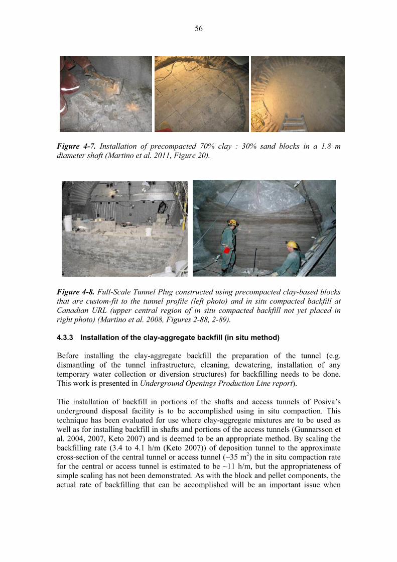
56
Figure 4-7. Installation of precompacted 70% clay : 30% sand blocks in a 1.8 m diameter shaft (Martino et al. 2011, Figure 20).
Figure 4-8. Full-Scale Tunnel Plug constructed using precompacted clay-based blocks that are custom-fit to the tunnel profile (left photo) and in situ compacted backfill at Canadian URL (upper central region of in situ compacted backfill not yet placed in right photo) (Martino et al. 2008, Figures 2-88, 2-89). 4.3.3 Installation of the clay-aggregate backfill (in situ method) Before installing the clay-aggregate backfill the preparation of the tunnel (e.g. dismantling of the tunnel infrastructure, cleaning, dewatering, installation of any temporary water collection or diversion structures) for backfilling needs to be done. This work is presented in Underground Openings Production Line report). The installation of backfill in portions of the shafts and access tunnels of Posiva’s underground disposal facility is to be accomplished using in situ compaction. This technique has been evaluated for use where clay-aggregate mixtures are to be used as well as for installing backfill in shafts and portions of the access tunnels (Gunnarsson et al. 2004, 2007, Keto 2007) and is deemed to be an appropriate method. By scaling the backfilling rate (3.4 to 4.1 h/m (Keto 2007)) of deposition tunnel to the approximate cross-section of the central tunnel or access tunnel (~35 m2) the in situ compaction rate for the central or access tunnel is estimated to be ~11 h/m, but the appropriateness of simple scaling has not been demonstrated. As with the block and pellet components, the actual rate of backfilling that can be accomplished will be an important issue when

57
evaluating how long the backfill front can be left open, and how well it tolerates inflowing water. In situ compaction has been utilized in large-scale tunnel backfilling trials and demonstrations at the Äspö facility in Sweden as well as a large number of smaller-scale field trials (Pusch 2002, Chapter 9-4, Gunnarsson et al. 2007, Table 5-4). Figure 4-9 shows examples how compaction of backfill into a full-scale tunnel could be accomplished and conduct of trials at Äspö. In order to optimise the compaction achieved using in situ compaction in tunnels careful attention must be paid to compaction pattern and the thickness of each layer of backfill installed (Gunnarsson et al. 2007, Korkiala-Tanttu et al. 2007).
Method of in situ compaction of tunnel backfill
Roller compaction in TBM tunnel at Äspö
Results of inclined compaction at Äspö
Figure 4-9. In situ compaction of backfill in tunnels (Gunnarsson et al. 2007, Fig. 5-9 and Pusch 2002 Figs. 9-6 and 9-10).
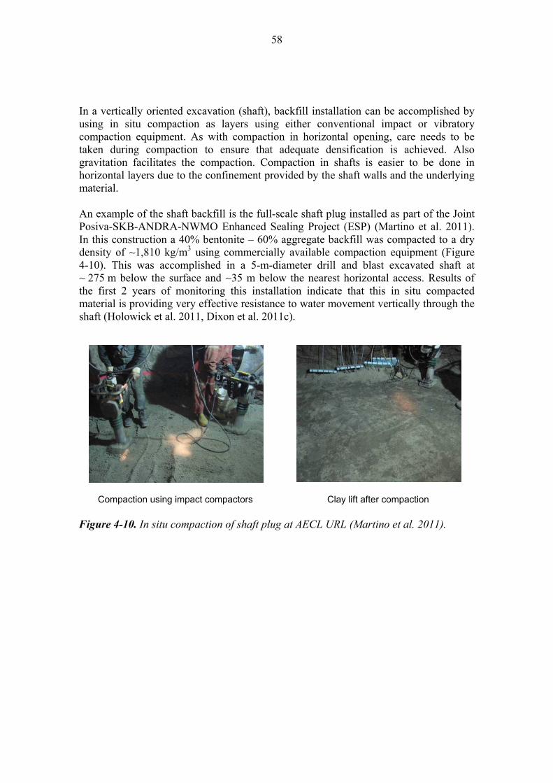
58
In a vertically oriented excavation (shaft), backfill installation can be accomplished by using in situ compaction as layers using either conventional impact or vibratory compaction equipment. As with compaction in horizontal opening, care needs to be taken during compaction to ensure that adequate densification is achieved. Also gravitation facilitates the compaction. Compaction in shafts is easier to be done in horizontal layers due to the confinement provided by the shaft walls and the underlying material. An example of the shaft backfill is the full-scale shaft plug installed as part of the Joint Posiva-SKB-ANDRA-NWMO Enhanced Sealing Project (ESP) (Martino et al. 2011). In this construction a 40% bentonite – 60% aggregate backfill was compacted to a dry density of ~1,810 kg/m3 using commercially available compaction equipment (Figure 4-10). This was accomplished in a 5-m-diameter drill and blast excavated shaft at ~ 275 m below the surface and ~35 m below the nearest horizontal access. Results of the first 2 years of monitoring this installation indicate that this in situ compacted material is providing very effective resistance to water movement vertically through the shaft (Holowick et al. 2011, Dixon et al. 2011c).
Compaction using impact compactors
Clay lift after compaction
Figure 4-10. In situ compaction of shaft plug at AECL URL (Martino et al. 2011).

59
4.3.4 Installation of the crushed rock material (in situ method)
Before installing the crushed rock backfill preparation of the tunnel (e.g. dismantling of the tunnel infra, cleaning, dewatering, installation of any temporary water collection or diversion structures) for backfilling needs to be done. This work is presented in Underground Openings Production Line report).
Posiva’s backfilling concept includes the use of considerable volumes of crushed rock to fill areas where low permeability fill is not necessary. Installation of the crushed rock fill will be accomplished via the same in situ compaction techniques as for the clay-crushed rock backfill. In situ compaction using conventional technologies (e.g. vibratory plate or impact compactors, roller compactors) has been demonstrated to perform in several experiments completed at SKB’s Äspö facility, in Riihimäki and elsewhere (Gunnarsson et al. 2007, Korkiala-Tanttu et al. 2007). Additionally, the compaction of crushed rock and other aggregate fill materials is a common activity within the civil construction industry (e.g. road railway and other embankments and excavation backfilling). The installation of crushed rock in tunnels is more challenging than for geometries where there is no roof present. The aggregate layers to be installed in access tunnel are inclined which is more challenging than horizontal ones. The mining industry has developed equipment and technologies that allows this to be accomplished and this is summarised by Dixon & Keto (2008) and Pusch (2008). Figure 4-9 shows examples of in situ compaction of crushed rock undertaken as part of large-scale experiments in Äspö. Besides that Figure 4-11 shows some of the other compaction equipment that can be used to install these materials. Compaction can be readily accomplished in these geometries but care must be taken to ensure that adequate densification is accomplished immediately adjacent to the backfill’s contact with the tunnel wall. The backfill must be designed and installed so that it will not settle too much under self-weigh generating preferential flow path (a gap) at the crown of the tunnel. Where settlement is unavoidable, gap formation can be accommodated through installation of material containing a substantial swelling clay component in the uppermost portions of the backfill (e.g. precompacted blocks or shotclay). Examples of this are shown in Figure 4-12 and Figure 4-13.
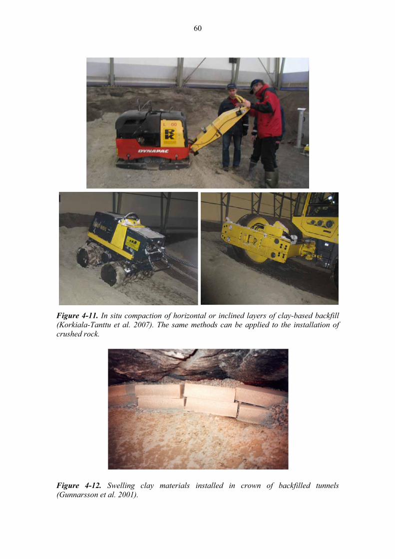
60
Figure 4-11. In situ compaction of horizontal or inclined layers of clay-based backfill (Korkiala-Tanttu et al. 2007). The same methods can be applied to the installation of crushed rock.
Figure 4-12. Swelling clay materials installed in crown of backfilled tunnels (Gunnarsson et al. 2001).

61
Figure 4-13. Intrusion of 70% clay – 30% aggregate material into settlement gap at crown of tunnel (Martino et al. 2008, Figure 8-32).
4.3.5 Principles of backfill quality assurance (QA) The quality assurance of the closure backfill as well as the various plugs installed in the course of underground disposal facility closure activities follows the principles set for quality assurance of the deposition tunnel backfill. The quality assurance of deposition tunnel backfill is described in detail in Backfill Production Line report. Backfilling of deposition tunnels overlaps in time with backfilling of the central tunnels of the panels where final disposal operation has already been done. The quality assurance protocols are quite similar than those for deposition tunnel backfill, even though the performance requirements for the materials may vary. It should also be noted that materials, which do not fulfil the criteria set for deposition tunnel backfill (e.g. swelling clay content in bentonite) may be acceptable for use in closure backfilling (where a low swelling clay content is acceptable). This means that a consistently applied QA process cannot only identify substandard materials but also identify opportunities to reduce waste by redirecting materials into another production line where they are useable. The quality assurance of the closure system will depend on several factors. These include consideration of: the performance requirements established for the various regions of the closure
system, the region being backfilled, its location, dimensions, geometry and accessibility, the sensitivity of overall system performance to potential variations in the
composition or performance of the various components of the closure system, and ability to install the backfill in a timely and consistent manner. In general, for the case of the central tunnel backfill where the block and pellet technique is used, adverse deviations from the planned initial state are most likely to be associated with either inadvertent under-filling of the tunnel or section of the tunnel

62
with blocks or under-filling of the gaps with pellets. In a region where in situ compaction is utilised, the most likely adverse deviation from planned initial state will again be associated with under-compaction of the backfill or possibly erosive loss of backfill caused by water flowing into the tunnel and across/through the backfilled volume. These situations both have the potential to cause a reduction in the density of the backfill and an associated reduction in their hydraulic (and swelling) characteristics. This is taken into account in conservative design (initial K-values) compared to the requirements as well as comprehensive quality control. Ultimately, if the installed foundation bed, block and pellet backfill, clay-aggregate backfill or crushed rock materials installed as part of the closure, does not fulfill the set specifications it must be removed and re-installed. Given the costs and technical difficulties associated with material removal, successful quality assurance programs and consistent manufacturing and placement processes are critical. As the installation of the first parts of the closure system (central tunnel backfill) will not occur until after 2071, development of a formal, detailed QA process for this component of the closure can await development until the deposition tunnel backfill QA program is developed. Closure QA specifications can then be developed based on the results of this work. Quality assurance of the raw materials The producer of the raw material is responsible for delivering a product that fulfills preset quality requirements. Currently it is assumed that raw clay material is delivered to Finland by the supplier and that Posiva takes care of transport from harbor, storage and handling of raw materials as well as manufacturing, installation and quality control. Several suppliers of raw materials can be accommodated through use of a standardized quality program and pre-qualification of alternative suppliers. The same basic QA process as used for the clay components in the buffer clay and deposition tunnel backfill clay will be applied to the closure backfill (although acceptance standards may be different for the closure backfill than for other clay materials). This QA process is described below. Factors that affect the decision on from where and how the raw material is acquired are discussed in Backfill Production Line report. The quality assurance of the raw material done by the supplier can include conduct of the following: sampling to allow for detailed material assessment by Posiva or independent QA
laboratory, mineralogical and chemical analyses, physical properties evaluation, and water content of the material. Posiva will evaluate the samples provided by the supplier before materials are accepted for shipping. These studies could include some or all of the following tests: water content, swelling index, granule size distribution, cation exchange capacity, original exchangeable cation composition, the determination of mineralogical and chemical composition, swelling pressure, hydraulic conductivity and compaction properties
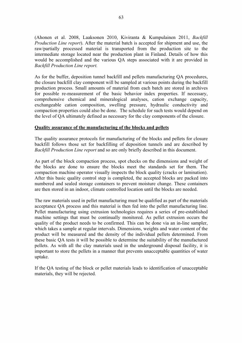
63
(Ahonen et al. 2008, Laaksonen 2010, Kiviranta & Kumpulainen 2011, Backfill Production Line report). After the material batch is accepted for shipment and use, the raw/partially processed material is transported from the production site to the intermediate storage located near the production plant in Finland. Details of how this would be accomplished and the various QA steps associated with it are provided in Backfill Production Line report. As for the buffer, deposition tunnel backfill and pellets manufacturing QA procedures, the closure backfill clay component will be sampled at various points during the backfill production process. Small amounts of material from each batch are stored in archives for possible re-measurement of the basic behavior index properties. If necessary, comprehensive chemical and mineralogical analyses, cation exchange capacity, exchangeable cation composition, swelling pressure, hydraulic conductivity and compaction properties could also be done. The schedule for such tests would depend on the level of QA ultimately defined as necessary for the clay components of the closure. Quality assurance of the manufacturing of the blocks and pellets The quality assurance protocols for manufacturing of the blocks and pellets for closure backfill follows those set for backfilling of deposition tunnels and are described by Backfill Production Line report and so are only briefly described in this document. As part of the block compaction process, spot checks on the dimensions and weight of the blocks are done to ensure the blocks meet the standards set for them. The compaction machine operator visually inspects the block quality (cracks or lamination). After this basic quality control step is completed, the accepted blocks are packed into numbered and sealed storage containers to prevent moisture change. These containers are then stored in an indoor, climate controlled location until the blocks are needed. The raw materials used in pellet manufacturing must be qualified as part of the materials acceptance QA process and this material is then fed into the pellet manufacturing line. Pellet manufacturing using extrusion technologies requires a series of pre-established machine settings that must be continually monitored. As pellet extrusion occurs the quality of the product needs to be confirmed. This can be done via an in-line sampler, which takes a sample at regular intervals. Dimensions, weights and water content of the product will be measured and the density of the individual pellets determined. From these basic QA tests it will be possible to determine the suitability of the manufactured pellets. As with all the clay materials used in the underground disposal facility, it is important to store the pellets in a manner that prevents unacceptable quantities of water uptake. If the QA testing of the block or pellet materials leads to identification of unacceptable materials, they will be rejected.

64
Quality assurance of the manufacturing of clay-aggregate mixture for foundation layer and in situ compacted backfills The primary QA processes associated with these components are: the grain-size distribution in granular bentonite (foundation bed) and the aggregate
component used in the in situ compacted materials, where a clay-aggregate material is used, confirmation of the dry mass proportion in
the mixture, and water content of clay aggregate mixtures. These are relatively simple to quality check and as there will likely be at least a few hours between batch preparation and its use, relatively simple quality control methods (e.g. dry sieving to confirm granular bentonite sizing, wet washing to confirm clay-aggregate ratio and gravimetric water content analysis) will provide confirmation of batch suitability or identify what remedial treatment will be needed to ensure its suitability. Quality assurance during the installation of the foundation layer, blocks and pellets. The quality assurance of the foundation layer of the closure backfill installation follows the principles set for backfill of deposition tunnels (Backfill Production Line report). This follows the basic process below: The dry mass needed in the foundation layer in order to achieve the density
required for a tunnel section is calculated based on the tunnel volume data. During foundation layer compaction, the degree of compaction achieved is
continuously monitored (here are different continuous compaction control systems available for roller compactors).
The dry density and water content of the layer could be checked regularly by sampling and compared to the calculated values.
The final thickness of foundation layer will be controlled for instance by laser scanning. The evenness and inclination of the surface can be controlled (laser scanning or tachymeter).
On completion of foundation layer installation, block placement will occur. QA is accomplished as follows: After the installation of each cross section of blocks, the facial evenness of the layer
is inspected by laser scanning and compared to the assembly tolerances. The distance between the blocks and rock walls is checked. Gap volume is used to calculate the mass of pellets that will need to be placed. The volume and weight of the pellet material and water to be used during installation process are recorded for each pellet-spraying sequence. QA of this placement stage is accomplished by: sampling regularly to check the dry density and water content of the installed pellet
mass, and

65
calculating the average dry density of the pellet fill based on tunnel volume data and mass of pellets installed on that specific tunnel volume.
Quality Assurance during installation of in situ compacted clay-aggregate and aggregate materials Installation of clay-aggregate and aggregate-only components of the closure requires a QA process that is as effective as those used in the other regions. In situ compaction of clay-aggregate materials will require the use of raw materials that have passed the materials screening and acceptance QA processes. These components will then need: mixing in a manner that allows for production of materials that meet the dry mass
proportioning; aggregate gradation and gravimetric water content requirements defined for the backfill,
the determination of the backfilled volume by measurement of the tunnel dimensions and the mass calculated from these dimensions, and
evaluation of the achieved density after the backfill is installed. This will be done in the same manner as used for the foundation bed.
As part of the QA process for regions containing clay-aggregate mixtures where the EMDD concept is valid, this parameter may be used as a quality control parameter. In situ compaction of aggregate materials also requires a QA process. The rock used will need to meet the size gradation and water content specifications set for the backfill and a consistent densification will also be needed. This can readily be accomplished as part of the material preparation process. The same approach as was used to determine tunnel volume and mass of material needed to achieve the target density for the regions where clay-aggregate mixtures were installed can be used in regions where aggregate-only fills are installed. 4.4 Production of closure plugs 4.4.1 Ordering, delivery and storage of the materials for closure plugs
Current thinking is that most of the raw materials needed for closure plugs will be ordered for delivery to the disposal facility location, and the end-products will be fabricated there. External suppliers can be considered, if needed. The possibility does exist to order manufactured clay-based materials from existing manufacturers (e.g. pellets, clay blocks). Steel components are to be prefabricated and big natural boulders can be acquired from Olkiluoto island, or elsewhere. Raw materials and components needed for closure plugs are presented in Table 4-2.

66
Table 4-2. Raw materials and components to be ordered and/or delivered to the site.
Plug component Raw material / ingredients
Manufacturing of the structure/ component at site
Purchase as prefabricated component
Concrete in plug (standard and low pH concrete)
Cement, Silica fume, Limestone filler, Sand and gravel, Other additives, Admixtures
X
Water tight seal in hydraulic plugs Swelling clay
X
Filter layer Aggregate of predetermined grain size distribution
X
Steel components (for reinforcement, tubes and pipes)
Steel X
Accessory parts (for moulds, support structures)
To be defined later X
Boulders and natural stones Boulders and natural stones
X (X)
For the plug components that will be manufactured at the disposal facility site the raw materials will be ordered and delivered to the storage or on-site warehouse or other suitable location. Material is inspected at the time of delivery and only materials that fulfill the preset criteria are accepted. In cases where the component is manufactured elsewhere, the raw materials used need to be quality checked and the manufactured components will also be inspected when delivered to the site. The inspection could include spot checks of the dimensions, weight, density, and strength of the manufactured component. The conditions set for storage (e.g. humidity and temperature) have to be carefully followed. All materials are ultimately delivered down to the tunnel when they are needed for the construction of a plug. Material transportation should be designed so that required conditions (e.g. humidity and temperature) are maintained or temporary storage should be available underground. Suitable temperature and humidity conditions are especially important for storage of cement, silica fume and clay materials. 4.4.2 Manufacturing the components of the closure plugs Concrete in plugs Before casting the concrete, the formworks are to be set up. Concrete is mixed according to the defined process with dry materials premixed and water is added immediately before casting. Watertight seal in hydraulic plugs Clay blocks and pellets used in the hydraulic plugs are produced at the disposal facility site. The methods are the same as for the block and pellet backfilling in the central tunnels.

67
Filter layers Filter layers associated with plugs consist of aggregate. The source material for this aggregate component is the excavated rock from the tunnels, which is stored at the disposal facility site and is later crushed and washed to achieve the required grain size distribution. In order to protect it from erosion, the filter materials must fulfill the filter criteria, which are based on the grain size distribution of the surrounding materials. Other components Steel components are commercially sourced and are not manufactured at the site. They are prefabricated according to the designs and delivered to the construction site where they are inspected to meet the requirements prior use. Accessory components Materials and components are needed for the formwork and support structures for casting the concrete. The actual formwork is constructed at the plug location, according to the design and local conditions. Materials will be defined later. Boulders and natural stones Natural stones and rock fill needed for the intrusion obstructing plugs are sourced from the excavated rock stored at the piles at the site. Stones of suitable sizes are selected for plugs. No crushing is needed. Large boulders with a diameter of some metres are to be acquired from Olkiluoto or elsewhere. Suitable boulders exist naturally in Finland and can thus be easily bought in the vicinity of the site. Before installation they are stored at the site. 4.4.3 Installation of the closure plugs Mechanical plugs Mechanical plugs vary in thickness, shape and material and details, depending on location (tunnel dimensions and the loads from groundwater pressure and swelling pressure of the adjacent tunnel backfill). Examples of mechanical plugs designed to an access tunnel (cross section ~35 m2) are presented in Figure 4-14. All possible plug alternatives or locations are not studied in this stage of design. Low pH concrete will be used below the hydraulically conductive structure HZ20, and above it conventional concretes or low pH concretes will be used. Before the installation of a plug, suitable locations for the excavation of notches for the concrete component should be selected. The placement should represent sparsely fractured or intact, dry, good quality rock and the strength of rock should be sufficient to accept the loads that the plug will be subjected to. The notch for a plug could be excavated as part of the normal tunnel excavation process. However, this is not reasonable in most cases, especially if the rock conditions ahead of the anticipated plug

68
location are not adequately known beforehand. Also the closure plan will be modified and become more detailed during the operation phase (next 50-100 years), and the most optimal plug locations are known at a relatively late stage of the operation. Therefore the most optimal plug locations are known at relatively late stage of operation. Open excavations are also subject to ongoing damage due to stress-conditions in the surrounding rock mass, as well as mechanical damage resulting from equipment transit across that location over the many years that the site remains open. The installation of the plug can be described in the following general steps: Before the sawing or the blasting of the notch, the rock surfaces are cleaned and
loose rock is removed. The notch is then sawn, bored or blasted (depending on the shape of a plug) to the
designed angle determined as achieving the location-specific requirements (e.g. loads) and loose rock is scaled.
A formwork behind the plug is constructed. It includes voids for installation of the tubes needed for installing the filter layer material behind the formwork and hoses for grouting the rock-plug interface.
The steel reinforcement (for avoiding the shrinkage) is constructed and anchored to the rock.
Sensors for monitoring the temperature and mechanical stresses are installed simultaneously with the steel reinforcement. The highest point of the formwork is equipped with an air tube, which allows for bleeding of air during the casting of the plug.
Before the casting of the concrete, the dry materials are delivered to the tunnel/plug location and then carefully mixed according to the designed recipe and mixing order. The concrete is cast as a single pour in order to minimize the formation of joints. As soon as the mould is filled with fresh concrete the air tube is closed.
As the concrete cures, the progress of hydration is monitored by way of tracking temperature change within the concrete. If needed, the concrete is cooled with cold water conveyed in the cooling pipes in order to diminish the risk for internal fracturing. This is of particular importance in plugs constructed using more thermally active, conventional, concrete.
As part of the curing process (cooling-related volume change), the concrete will shrink, and the empty spaces between rock and concrete will need to be sealed by grouting.
Grouting is to be done after removal of the moulds and will be done through pre-installed grout tubes that intersect the rock-concrete interface.
The formwork is removed as soon as the concrete has reached sufficient strength. After the formwork is removed, the void space between the previously installed
tunnel backfill and the newly cast plug is filled with sand or gravel. Finally the grout tubes are sealed with concrete.
Besides the adjacent backfill, depth and location, the details of the construction of plugs depends on the material and type of formwork, and those will be determined in later design stages.

69
Hydraulic plugs Hydraulic plugs vary in thickness, shape, material and details, depending on the location and loads. The loads and local conditions will influence to the final design of hydraulic plugs, and the plugs presented here are examples of possible structures, which will be designed more detailed in the later design stages. An example of a hydraulic plug designed for an access tunnel (cross section ~ 35 m2) is presented in Figure 4-15. All possible plug alternatives or locations have not been evaluated at this stage of design. Low pH concrete will be used below the hydraulically conductive structure HZ20, and above it conventional concrete or low pH concrete will be used. The basic design for a hydraulic plug includes two similar concrete structures (which are basically identical to mechanical plug) and between them a water-tight seal of swelling clay, which is supported by filter layers after the concrete has degraded. The basic design for concrete structures is the same as for mechanical plugs, and thus the installation is also similar. The details of the installation vary depending on the adjacent backfill, depth and location as well as on the formwork solution. The construction of a hydraulic plug has the additional steps of installing the clay blocks and pellets as well as filter layers between the outermost concrete components. Clay blocks and pellets will be installed in the same way as in the central tunnels.
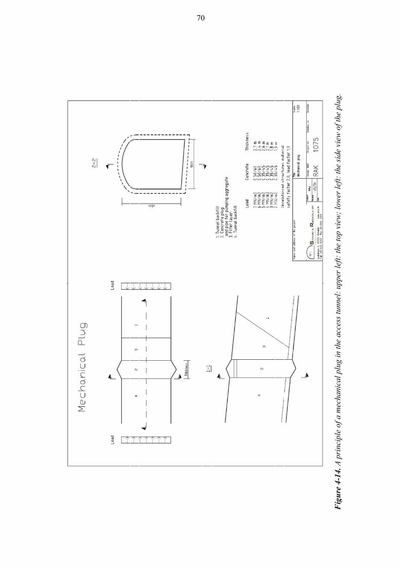
70
F
igu
re 4
-14.
A p
rinc
iple
of a
mec
hani
cal p
lug
in th
e ac
cess
tunn
el:
uppe
r le
ft:
the
top
view
; lo
wer
left
: th
e si
de v
iew
of t
he p
lug.

71
Fig
ure
4-1
5. A
con
cept
ual l
ayou
t of a
hyd
raul
ic p
lug
in th
e ac
cess
tunn
el:
uppe
r le
ft:
the
top
view
and
low
er le
ft:
side
vie
w o
f the
plu
g

72
Human intrusion obstructing plugs The installation of human intrusion obstructing plugs is technically simple and consists of four stages: Filter layer is installed. Boulders are driven and pushed to the intended locations. Concrete basement is cast. Natural stones are driven on the mouth of the access tunnel and the shafts.
Finally the surroundings are landscaped. 4.4.4 Principles for the quality assurance of the plugs Material inspection of the concrete components shall follow the prevailing norms and standards, and inspections could include for example spot checks of the quality of the dry materials (e.g. chemical and mineralogical studies, grain size distribution). Material is inspected at the time of delivery and only materials that fulfill the preset criteria are accepted. The conditions set for storage (e.g. humidity and temperature) have to be carefully followed. The clay components are quality controlled by the same principles as those for clay blocks and pellets for central or deposition tunnels. A detailed description of how this process would be followed for the bentonite component is described in Backfill Production Line report and Ahonen et al. (2008). In order to inspect the quality of the components of concrete plugs and quality of the cast concrete components the following measures are to be made: The amounts of materials used in construction will be measured and recorded. Systematic checks of the materials delivered to the construction site will be done.
They may include tests on raw material quality, or inspections on package and its markings.
Test castings of the concretes and measurement of their properties according to the prevailing norms and standards will be done.
Monitoring of the temperature and other properties during the casting of concrete will be done.
Ground penetration radar or ultrasonic inspection is used to inspect the uniformity of cast structures.
Free surfaces are inspected visually and with Schmidt hammer. Monitoring of plugs can be done before both sides of a plug are backfilled. Also repairing is possible, if needed. Long term monitoring of the closure plugs is not intended to be carried out.

73
4.5 Production and quality assurance of the closure of the investigation boreholes
The procedure for closing an investigation hole has the following phases (Karvonen 2012): 1. cleaning the borehole, 2. characterization of the borehole, 3. stabilizing the weak sections, 4. replacing the water, 5. closing the borehole, 6. installing the surface plug, and 7. installing the upper material. Prior to installing the closure materials, an investigation hole is emptied of any equipment that was left behind during its use. After this the investigation hole is washed with water and a brush installed to drilling equipment (Rautio et al. 2004, Rautio 2002, 2005). After cleaning the investigation hole it is characterized by measuring the caliber and using a dummy closure installation device in order to ensure easy access to the bottom of the investigation borehole and up again. If needed, optical imaging can also be performed as done in borehole plugging experiment of OL-KR24 (Rautio 2006, p. 13-17). Replacing of the water standing in the borehole is needed in the Basic Method in order to avoid problems in installation of borehole backfill. Fresh water allows longer installation time than saline. The replacement can be done by pumping fresh water to the bottom of the investigation hole to dilute the salinity. It is probable that this dilution does not persist, and it should be done immediately before each installation of a Basic Method borehole backfill section (Pusch & Ramqvist 2008, p. 17). Concrete plugs are cast in investigation holes via drilling rods that have been lowered in place and lifted as concrete is pumped down (Rautio 2006, p. 37 and 40-41). After hardening the depth is ensured to be correct. Hardening of the concrete takes from one to few days and cup samples taken from the mixed concrete batch indicate the state of setting (Rautio 2006, p. 24, Karvonen 2012). At least one reference sample should be stored in similar conditions (water salinity and temperature) as the plug in the investigation borehole to indicate the correct setting time. When the setting of concrete has been verified with drilling equipment, and the depth is correct, borehole backfill can be installed above it. The Container Method for borehole backfill placement is still under development but conventional drilling equipment will be used also with this method. A piston will push the bottom plate and the borehole backfill out of the container at preset pressure (Pusch & Ramqvist 2008, p. 20). If the Basic Method is used the tubes can be lowered using drilling equipment and a transport instrument as presented by Rautio (2006, p. 38). The surface plug will be lowered to the bottom of the casing that is in the upper part of a borehole and which is wider than the investigation hole below. If the casing is not wide enough, or extends far enough down, the investigation hole will be enlarged by over

74
coring to the depth of approximately 30 m. Then the surface plug will be placed to the bottom of this newly widened section. Above the surface plug the investigation hole will be filled with so-called upper material, which is rock material or concrete (Karvonen 2012). There may be stability problems in some investigation holes and stabilization may be necessary. If so, it will be done by reaming the section to be stabilized to a larger diameter, filling this section with cement and then re-drilling the investigation hole through the cement thus leaving “a cement ring” to support the walls (Karvonen 2012, Pusch & Ramqvist 2008, p. 39, Rautio 2006, p. 19-33). Quality assurance will follow similar pattern with other concrete structures and bentonite utilizing EBS components. With boreholes the emphasis is in controlling the quality of the materials and production, as it is not feasible to inspect the final produced borehole closure at depth. A detailed plan for quality assurance including quality control in different phases (raw materials, manufacturing the backfill and plugs and emplacement of backfill and plugs) will be available before the investigation hole closure phase is actual.
75
5 INITIAL STATE 5.1 General The initial state refers to the properties of an engineered barrier (here closure) at the time it is installed in the underground disposal facility and is no longer accessible for conduct of any subsequent engineering measures i.e. when measures of direct control for the barrier are lost. The changes in closure materials that occur after their installation (e.g. saturation of the closed tunnels) do not represent the initial state. Basically, the initial state of each of the closure components in the tunnels and investigation holes is defined by their physical, hydraulic, chemical and other conditions present at the time when emplaced. How the closure will look at the beginning of the post-closure phase is given in Figure 5-1. The time of the initial state can be very different for the last closure component and the first installed canister in the repository system, up to about 100 years. In Figure 4-1 the emplacement times anticipated for different components are indicated with approximate numbers to give an overview of the step-wise approach (as predicted today). As the design of the closure is not finalized, changes can and are to be made for the materials and design during the future operations. However, the requirements set for the closure (Design Basis) provide a guideline for further development work. As it has been noted throughout this report, there are alternative solutions and materials for backfilling the underground disposal facility that can also meet the requirements set for its performance. For the reference design of the closure, these alternatives are described in Dixon et al. (2012). Geometries of the underground disposal facility to be closed are presented by Saanio et al. (2012). 5.2 Initial state of the closure materials Eventually, due to the selected flexible tool box approach for the closure there will be several types of backfills in the underground disposal facility when it is closed. The initial states are given for the various components of the reference closure design. Within these descriptions possible ranges of the key performance parameters are given as well as linkages to previous text locations in this document and references to other reports where these are discussed. This report presents the reference design, the background and alternatives are discussed by Dixon et al. (2012). The initial state of the backfill materials represent the moment when it is emplaced.

76
F
igu
re 5
-1.
A r
efer
ence
des
ign
for
the
clos
ure.
The
ini
tial
sta
te i
s de
term
ined
for
the
mom
ents
the
clo
sure
com
pone
nts
are
inst
alle
d.
77
5.2.1 Closure backfill The design specifications will depend on several factors. These include consideration of: the region being backfilled, its location, dimensions, geometry and accessibility, the performance requirements established for the various regions of the closure
system, the sensitivity of overall system performance to potential variations in the
composition or performance of the various components of the closure system, and the ability to install the backfill in a timely and consistent manner. The initial state required and to be reached by the closure backfill is compiled in Table 5-1. The reference design, which describes where the materials are needed, is presented in Chapter 3. A primary target for closure backfill behaviour is to ensure that it provides adequate resistance to water movement through the underground disposal facility between the repository and ground surface. By estimating what could reasonably occur in a moderate deviation from the initial state, a sufficiently conservative behavioural margin to have confidence in system behaviour can be provided. For example, if a backfilled region is required to have a hydraulic conductivity of 10-9 m/s then the reference design (and thus its initial state) has been defined such that its behaviour is predicted to be <10-10 m/s. This order-of-magnitude margin provides for conservative performance and a substantial margin to accommodate deviation in initial conditions or source material quality. Based on the discussion provided in Section 3.6, installing clay or clay-crushed rock materials that much exceed the initial performance criteria will not be problematic. For each region of closure backfilling that has clearly defined hydraulic requirements (Table 3-1 and Table 5-1), the conservative design approach described above will allow for confidence in system performance to be maintained. It will also build in a performance margin to the closure such that if a need for modest tightening of requirements were to be identified during performance assessment evaluations, the initial conditions will still be adequate and changes in materials or densities can be avoided or at least minimised. In regions where swelling clays are used as part of the backfill, definition of a behavioural margin is relatively straight forward. The EMDD parameter (Section 3.5, Figure 3-5) has been used as a guide in defining the density margin required to accommodate modest deviations from initial state for materials containing more than 25% smectite-rich clay components (Dixon 2000). These backfills have the ability to swell into voids or compress adjacent materials such that the performance of adjacent sub-standard backfill is improved and system performance goals are met. Component initial densities provided in Table 5-1 are based on assumed swelling clay component being Friedland Clay, and an average clay-aggregate component of either 40-60 or 30-70 in the volumes to be backfilled. This is presented in more detail in Appendix B-2

78
In general, for the central tunnel backfill where the block and pellet technique is used, adverse deviations from the planned initial state are most likely to be associated with either inadvertent under-filling of the tunnel or section of the tunnel with blocks or under-filling of the gaps with pellets. In a region where in situ compaction is utilised, the most likely adverse deviation from planned initial state will again be associated with under-compaction of the backfill or possibly erosive loss of backfill caused by water flowing into the tunnel and across/through the backfilled volume. These situations both have the potential to cause a reduction in the density of the backfill and an associated reduction in their hydraulic (and swelling) characteristics. It is possible that the emplaced backfill exceeds its requirements for the initial state. In such situations there are no adverse performance repercussions likely, excepting perhaps for a higher-than anticipated swelling pressure. Provided that adjacent materials and structures (plugs) are able to accommodate higher contact pressure (e.g. increase from 50 kPa to 150 kPa), there is no need to remediate a region where as-placed density is better than required. Where, for whatever reason, the initial state is not met (or exceeded), there is a need to have confidence that the materials actually installed will meet the performance requirements for the closure backfill. Otherwise it may be necessary to excavate the volume in question and reinstall the backfill. The most appropriate means of avoiding disruptive and expensive excavation and re-installation of the closure backfill is to install materials that have sufficient behavioural margin to assure adequate performance under reasonably defined deviations in initial state conditions. This approach is used in defining the minimum initial state specifications for closure materials discussed in Chapter 5.

79
Tab
le 5
-1. I
niti
al s
tate
of t
he c
losu
re b
ackf
ills
bas
ed o
n hy
drau
lic
cond
ucti
vity
(K
) sp
ecif
icat
ions
. L
oca
tio
n o
f b
ackf
ill
Mat
eria
l u
sed
an
d
com
pac
tio
n
tech
niq
ue
Dep
th
(m)
Vo
lum
e In
stal
led
(m
3)
Req
uir
ed K
(m/s
)
Init
ial S
tate
K
* (m
/s)
Init
ial
Dry
Den
sity
**
(kg
/m3)
Init
ial
Wat
er C
on
ten
t (%
) O
ther
**
Cen
tra
l tun
nel
s,
Link
ing
tunn
els
, C
onne
ctin
g T
unne
ls
(low
est
part
of
shaf
ts
excl
ude
d)
Frie
dla
nd
bloc
ks &
ben
toni
te
pelle
ts
Fou
ndat
ion
bed
-420
to -
455
377
000
28 0
00-
10
5 0
00
16
00
0 –
62
00
0
≤ 1E
-9
≤ 1E
-10
Pel
lets
100
0
Blo
cks
>20
00
Fou
ndat
ion
bed
>17
00
16**
* 6-
10**
* ~
12**
*
Blo
ck a
nd
Pel
let b
ackf
ill,
100
% c
lay
Acc
ess
tunn
els
, S
hafts
Cla
y-
aggr
egat
e
in s
itu**
-200
to -
420
95
00
0
≤ 1E
-8
≤ 1E
-9
≤
1E-9
170
0
17
00
~14
***
~
12**
*
40/6
0 m
ix
30
/70
mix
Acc
ess
tunn
el,
Enc
apsu
latio
n w
ast
e re
posi
tory
S
hafts
T
echn
ical
roo
ms
Bac
kfill
bet
wee
n h
ydra
ulic
plu
gs w
hic
h is
olat
e fr
actu
re z
one
Cru
shed
roc
k
in s
itu
Sur
face
to
-200
28
8 0
00
≤ 1E
-7
≤ 1E
-8
≥ 21
00
N
ot D
efin
ed
Cru
shed
an
d gr
aded
ag
greg
ate
Sur
face
Bou
lder
s 0
to -
30
Not
Def
ined
N
ot D
efin
ed
Not
Def
ined
N
ot D
efin
ed
Not
Def
ined
* I
niti
al s
tate
bas
ed o
n pr
ovid
ing
a 1-
orde
r of
mag
nitu
de m
argi
n to
K o
f as
-pla
ced
mat
eria
ls
** B
ackf
ill
com
posi
tion
req
uire
d w
ill v
ary
wit
h lo
cal
cond
itio
ns a
nd d
epth
, as
wel
l as
fin
al f
orm
ulat
ion
of b
ackf
ill.
Den
siti
es p
rovi
ded
are
for
mat
eria
ls o
f 30
-70
and
40-6
0 be
nton
ite
– ag
greg
ate
mix
ture
s (b
y dr
y m
ass
prop
orti
ons)
. Loc
al g
roun
dwat
er c
ompo
siti
on w
ill
also
aff
ect
init
ial s
tate
den
sity
req
uire
men
ts. F
or t
he p
urpo
ses
of th
ese
esti
mat
es a
3.5
– 7
% g
roun
dwat
er T
DS
is
assu
med
and
Fig
ure
3-5
is
used
to e
stim
ate
K r
equi
rem
ents
. See
App
endi
x B
for
det
aile
d ev
alua
tion
s of
mat
eria
ls.
***
Init
ial w
ater
con
tent
wil
l dep
end
on s
peci
fic
mat
eria
ls s
elec
ted,
typi
call
y so
met
hing
sli
ghtl
y dr
y of
opt
imum
wat
er c
onte
nt w
ould
be
expe
cted
.

80
5.2.2 Closure plugs In principle the initial state of a closure plug is the state following construction (intentionally). Effects of construction that are not intended or are a side effect of other activities are considered in analysis of the operational phase evolution. Plugs may be composed of several materials (clay, grout, concrete, crushed rock), which are considered as a single unit that has its own initial state. According to the reference design there can be three types of plugs present at the initial state of the closure: hydraulic, mechanical and human intrusion obstructing plugs. The shape, dimensions and the compositions of the plug structures vary depending on their location in the system. For the plugs below hydrogeological zone HZ20 the recipe for a low pH concrete is presented in Table 5-2. The water to dry material ratio of this concrete is 0.29 and the density is 2,335 kg/m3. Above the HZ20 zone standard concrete mixes can be used and an example of a mix is given in Table 5-3. The water to dry material ratio of this concrete is 0.35 and the density is between 2,305-2,315 kg/m3. The initial state of clay block and pellet material used in the hydraulic plugs is not formally defined and will depend on a) the selected material(s) b) the location of a hydraulic plug and c) individual performance of each hydraulic plug, which will be established in later design stages. For the purposes of the reference design of the closure, it is assumed that the clay blocks and pellets used in the hydraulic plugs will be prepared from bentonite clay materials having a substantial swelling clay component. These materials will for the most part have densities, compositions and initial states comparable to the block and pellet materials used in the deposition tunnel backfill (described in detail by Backfill Production Line report). In these plugging structures there will be additional materials besides concrete and clay. These include crushed rock of as-yet undefined composition and grain size gradation, the initial state of these materials can only be defined once formal design and construction specifications are developed. Intrusion obstructing plugs consists mainly of boulders, natural stones and aggregate. They have no clearly defined performance or initial state properties related to chemistry, density or hydraulic conductivity. However, they will consist of typical rock types (i.e. minerals) of Finnish bedrock. Concrete (Table 5-3) is used in accessory parts. They are to serve purely as impediment structures and thus hydraulic conductivity and density do not play a role in these plugs.
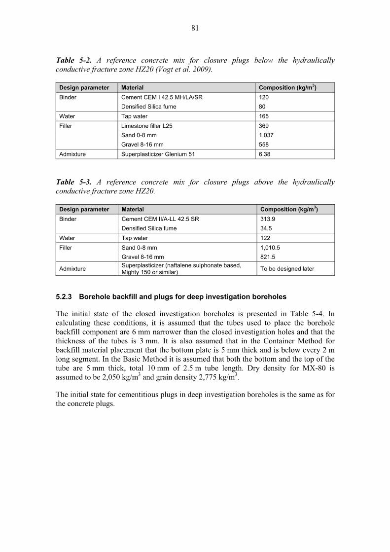
81
Table 5-2. A reference concrete mix for closure plugs below the hydraulically conductive fracture zone HZ20 (Vogt et al. 2009).
Design parameter Material Composition (kg/m3)
Binder Cement CEM I 42.5 MH/LA/SR 120
Densified Silica fume 80
Water Tap water 165
Filler Limestone filler L25 369
Sand 0-8 mm 1,037
Gravel 8-16 mm 558
Admixture Superplasticizer Glenium 51 6.38
Table 5-3. A reference concrete mix for closure plugs above the hydraulically conductive fracture zone HZ20.
Design parameter Material Composition (kg/m3)
Binder Cement CEM II/A-LL 42.5 SR 313.9
Densified Silica fume 34.5
Water Tap water 122
Filler Sand 0-8 mm 1,010.5
Gravel 8-16 mm 821.5
Admixture Superplasticizer (naftalene sulphonate based, Mighty 150 or similar)
To be designed later
5.2.3 Borehole backfill and plugs for deep investigation boreholes The initial state of the closed investigation boreholes is presented in Table 5-4. In calculating these conditions, it is assumed that the tubes used to place the borehole backfill component are 6 mm narrower than the closed investigation holes and that the thickness of the tubes is 3 mm. It is also assumed that in the Container Method for backfill material placement that the bottom plate is 5 mm thick and is below every 2 m long segment. In the Basic Method it is assumed that both the bottom and the top of the tube are 5 mm thick, total 10 mm of 2.5 m tube length. Dry density for MX-80 is assumed to be 2,050 kg/m3 and grain density 2,775 kg/m3. The initial state for cementitious plugs in deep investigation boreholes is the same as for the concrete plugs.
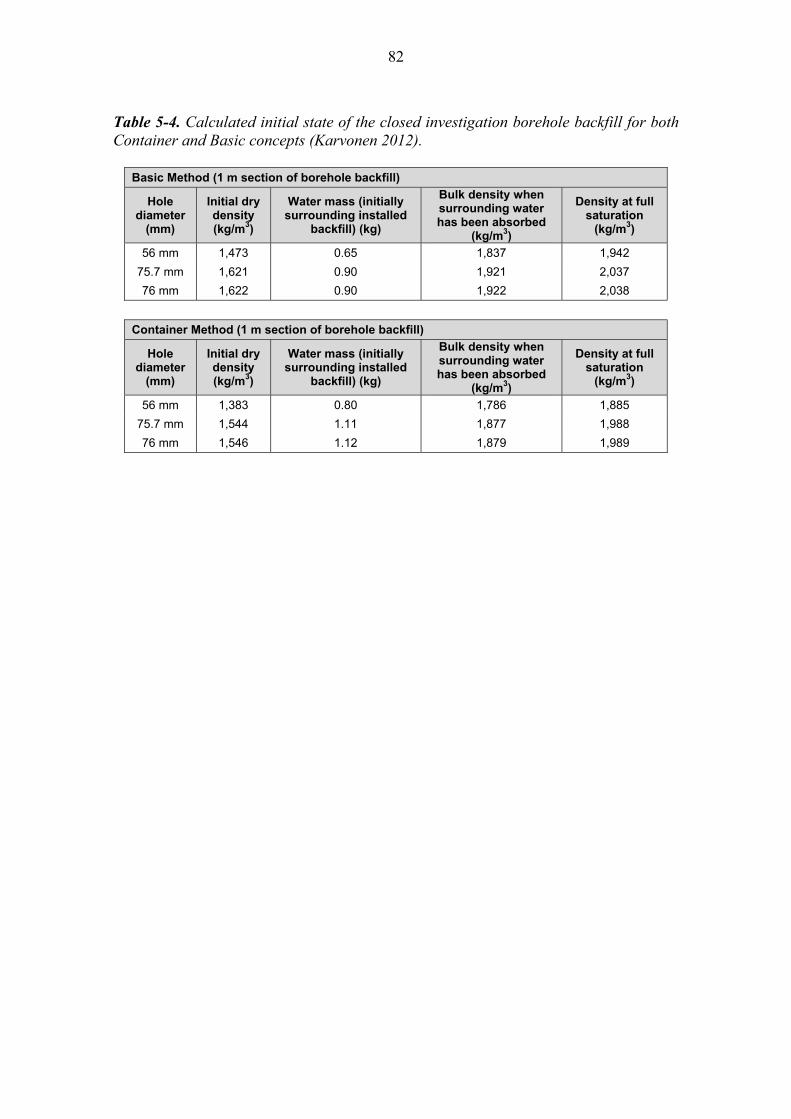
82
Table 5-4. Calculated initial state of the closed investigation borehole backfill for both Container and Basic concepts (Karvonen 2012).
Basic Method (1 m section of borehole backfill)
Hole diameter
(mm)
Initial dry density (kg/m3)
Water mass (initially surrounding installed
backfill) (kg)
Bulk density when surrounding water has been absorbed
(kg/m3)
Density at full saturation
(kg/m3)
56 mm 1,473 0.65 1,837 1,942
75.7 mm 1,621 0.90 1,921 2,037
76 mm 1,622 0.90 1,922 2,038
Container Method (1 m section of borehole backfill)
Hole diameter
(mm)
Initial dry density (kg/m3)
Water mass (initially surrounding installed
backfill) (kg)
Bulk density when surrounding water has been absorbed
(kg/m3)
Density at full saturation
(kg/m3)
56 mm 1,383 0.80 1,786 1,885
75.7 mm 1,544 1.11 1,877 1,988
76 mm 1,546 1.12 1,879 1,989
83
6 SUMMARY This document provides a brief description of the underground disposal facility closure approach proposed for implementation in Posiva’s deep geological disposal facility for spent nuclear fuel. Description of a reference method to achieve closure of the underground disposal facility excavations beyond the plugs installed at the entrance of each deposition tunnel has been provided. General guidelines for installation of a closure system that will meet the long-term safety-related requirements; performance targets, design requirements and design specifications for closure backfill, closure plugs and borehole sealing have been developed and described. Materials deemed capable of meeting these guidelines have been identified and the manner in which material could be installed has been presented. The selected approach for the closure of the underground disposal facility is based on prevailing geological and hydrogeological conditions at the site. One important clue in the selected reference design is to restore the natural conditions after the operational and closure phases of the underground disposal facility. Besides this, other EBS components and host rock have set up either limitations or requirements for the closure. Expected phenomena in the near and far future are taken into account in the design. The reference design for the closure can be briefly described as follows: Central tunnels are backfilled with blocks and pellets of swelling clay and they are
isolated from other areas by hydraulic plugs. Mechanical plugs will be used only if needed.
Vehicle connections are backfilled with aggregate-swelling clay mixtures installed in situ.
Technical rooms are backfilled with crushed rock. Hydraulic plugs are used to isolate the tunnels backfilled with different material or
where they are required for isolating hydraulic features. Mechanical plugs will be used only if needed to support installed backfill. Access tunnel and the shafts are backfilled mainly either with clay-aggregate
mixtures (in situ) or crushed rock, depending on the natural conditions of bedrock or other reasons explained in the report. Hydraulically conductive major fracture zones HZ20 and HZ19 are isolated from the backfilled tunnel with hydraulic plugs. Mechanical plugs will be used only if needed.
Finally the mouth of the access tunnel and shafts are closed with intrusion obstructing plugs.
In addition to the closure of the underground disposal facility, the sealing of the deep investigation boreholes belongs to the underground disposal facility closure responsibility. They are to be closed with same key principles; as the intention is restore the natural conditions of rock and to close the flow paths from the repository level to the ground surface, the tight borehole sections are backfilled with tight backfill material and plugs are to be used in the fractured or water conductive borehole sections. A flexible tool box approach is adopted for the backfill. Practically this is due to the reason that the set requirements can be achieved with wide range of choices. These are meaningful to be selected according to the conditions at hand.

84
It should be noted that the closure activities associated with the underground disposal facility are not anticipated to begin until after several decades (after year ~ 2070). This provides time for ongoing development of materials and methods for installing closure components that optimize the current reference approach. It will also allow time for testing and demonstration of the effectiveness of these components of the engineered barrier system. As the knowledge enhances, changes in the reference design are expected and will be done as the design proceeds further.
85
7 REFERENCES Safety case portfolio main reports: Design Basis Safety case for the disposal of spent nuclear fuel at Olkiluoto 2012 - Design Basis. Eurajoki, Finland: Posiva Oy. POSIVA 2012-03. ISBN 978-951-652-184-1. Performance Assessment Safety case for the disposal of spent nuclear fuel at Olkiluoto 2012 - Performance Assessment. Eurajoki, Finland: Posiva Oy. POSIVA 2012-04. ISBN 978-951-652-185-8. Description of the Disposal System Safety case for the disposal of spent nuclear fuel at Olkiluoto 2012 - Description of the Disposal System. Eurajoki, Finland: Posiva Oy. POSIVA 2012-05. ISBN 978-951-652-186-5. Features, Events and Processes Safety case for the disposal of spent nuclear fuel at Olkiluoto 2012 - Features, Events and Processes. Eurajoki, Finland: Posiva Oy. POSIVA 2012-07. ISBN 978-951-652-188-9. Safety case portfolio supporting reports: Backfill Production Line 2012. Design, production and initial state of the deposition tunnel backfill and plug. Eurajoki, Finland: Posiva Oy. POSIVA 2012-18. ISBN 978-951-652-199-5. Underground Openings Production Line 2012. Design, production and initial state of the underground openings. Eurajoki, Finland: Posiva Oy. POSIVA 2012-22. ISBN 978-951-652-203-9. Other references: Ahonen, L., Korkeakoski, P., Tiljander, M., Kivikoski, H. & Laaksonen, R. 2008. Quality assurance of the bentonite material. Eurajoki, Finland: Posiva Oy. Working Report 2008-33. Chandler, N.A., Cornut, A., Dixon, D., Fairhurst, C., Hansen, F., Gray, M,. Hara, K., Ishijima, Y., Kozak, E., Martino, J., Masumoto, K., McCrank, G., Sugita, Y., Thompson, P., Tillerson, J. & Vignal, B. 2002. The five year report on the tunnel sealing experiment: An international project of AECL, JNC, ANDRA and WIPP. Chalk River, Canada: Atomic Energy of Canada Limited (AECL). AECL-12127.

86
Dahlström, L-O. 2009. Experiences from the design and construction of plug II in the Prototype Repository. Stockholm, Sweden: Swedish Nuclear Fuel and Waste Management Co. (SKB). R-09-49. Dixon, D. 2000. Porewater salinity and the development of swelling pressure in bentonite-based buffer and backfill materials. Helsinki, Finland: Posiva Oy. POSIVA 2000-4. ISBN 951-652-090-1. Dixon, D. & Keto, P. 2008. Backfilling techniques and materials in underground excavations: Potential alternative backfill materials for use in Posiva’s spent fuel repository concept. Eurajoki, Finland: Posiva Oy. Working Report 2008-56. Dixon, D., Lundin, C., Örtendahl, E., Hedin, M. & Ramqvist. G. 2008a. Deep repository - Engineered barrier systems. Half scale tests to examine water uptake by bentonite pellets in a block-pellet backfill system. Stockholm, Sweden: Swedish Nuclear Fuel and Waste Management Co. (SKB). R-08-132. Dixon, D., Anttila, S., Viitanen, M. & Keto, P. 2008b. Tests to determine water uptake behaviour of tunnel backfill. Stockholm, Sweden: Swedish Nuclear Fuel and Waste Management Co. (SKB). R-08-134. Dixon, D.A., Martino, J.B. & Onagi, D. P. 2009. Enhanced Sealing Project (ESP): Design. Construction and Instrumentation Plan. Canada: Nuclear Waste Management Organization (NWMO). APM-REP-01601-0001. Dixon, D., Sandén, T., Jonsson, E. & Hansen, J. 2011a. Backfilling of deposition tunnels: Use of bentonite pellets. Stockholm, Sweden: Swedish Nuclear Fuel and Waste Management Co. (SKB). P-11-44. Dixon, D., Jonsson, E., Hansen, J., Hedin, M. & Ramqvist, G. 2011b. Effect of Localized Water Uptake on Backfill Hydration and Water Movement in a Backfilled Tunnel: Half-Scale Tests at Äspö Bentonite Laboratory. Stockholm, Sweden: Swedish Nuclear Fuel and Waste Management Co. (SKB). R-11-27. Dixon, D. A., Martino, J. B., Holowick, B. & Priyanto, D. 2011c. Enhanced sealing project: monitoring the THM response of a full-scale shaft seal. Proc. Canadian Nuclear Society Conference. Waste Management. Decommissioning and Environmental Restoration for Canada’s Nuclear Activities. 2011 Sept 11-14. Toronto, Canada. Dixon, D., Sievänen, U., Karvonen, T.H., Marcos, N., Hansen, J. & Korkiala-Tanttu, L. 2012. Underground disposal facility closure design 2012. Posiva Oy, Eurajoki, Finland. Working Report 2012-09. Gardemeister, R., Johansson, S., Korhonen, P., Patrikainen, P., Tuisku, T. & Vähäsarja, P. 1976. Application of engineering rock mass classification. Espoo, Finland: Technical research centre of Finland.

87
Gunnarsson, D., Johannesson, L-E., Sanden, T. & Börgesson, L. 1996. Field Test of Tunnel Backfilling. Stockholm, Sweden: Swedish Nuclear Fuel and Waste Management Company Co. (SKB). HRL-96-28. Gunnarsson, D., Börgesson, L., Hökmark, H., Johannesson, L.-E. & Sandén, T. 2001. Report on the installation of the backfill and plug test. Stockholm, Sweden: Swedish Nuclear Fuel and Waste Management Co. (SKB). IPR-01-17. Gunnarsson, D., Börgesson, L., Hokmark, H., Johannesson, L.-E. & Sandén, T. 2002. Installation of the Backfill and Plug Test. In: Clays in natural and engineered barriers for radioactive waste confinement: Experiments in Underground Laboratories. 2002. Chatenay-Malabry Cedex. ANDRA Science and Technology Series Report. ISBN: 2-9510108-5-0. Gunnarsson, D., Börgesson, L., Keto, P., Tolppanen, P. & Hansen, J. 2004. Backfilling and closure of the deep repository – Assessment of backfill concepts. Eurajoki, Finland: Posiva Oy. Working Report 2003-77 (also published as SKB R-04-53). Gunnarsson, D., Keto, P., Morén, L. & Sellin, P. 2007. Deep repository – Backfill and closure: Assessment of backfill materials and methods for deposition tunnels. Eurajoki, Finland: Posiva Oy. Working Report 2006-64. Hansen, J., Korkiala-Tanttu, L., Keski-Kuha, E. & Keto, P. 2009. Deposition tunnel backfill design for KBS-3V repository. Eurajoki, Finland: Posiva Oy. Working Report 2009-129. Holt, E. & Peura, J. 2011. Buffer component manufacturing by uniaxial compression method – Small scale. Eurajoki, Finland: Posiva Oy. Working Report 2011-42. Holowick, B., Dixon, D. A. & Martino, J. B. 2011. Enhanced Sealing Project (ESP): Project status and data report for period ending 31 December 2010. Toronto, Canada: Nuclear Waste Management Organization (NWMO). APM-REP-01601-0004. Johannesson, L.-E., Gunnarsson, D., Sandén, T., Börgesson, L. & Karlzén, R. 2004. Prototype Repository: Installation of buffer, canisters, backfill, plug and instruments in Section II. Stockholm, Sweden: Swedish Nuclear Fuel and Waste Management Co. (SKB). IPR-04-13. Johannesson, L.-E. & Nilsson, U. 2006. Deep repository – Engineered barrier systems; Geotechnical behaviour of candidate backfill materials. Laboratory tests and calculations for determining performance of the backfill. Stockholm, Sweden: Swedish Nuclear Fuel and Waste Management Co. (SKB). R-06-73. Karvonen, T.H. 2012. Closure of the investigation boreholes. Eurajoki, Finland: Posiva Oy. Working Report 2012-63. Keto, P. 2007. Backfilling of deposition tunnels. In situ Alternative. Eurajoki, Finland: Posiva Oy. Working Report 2006-90.

88
Keto, P., Dixon, D., Gunnarsson, D., Johnsson, E., Börgesson, L. & Hansen, J. 2009. Assessment of backfill design for KBS-3V repository. Olkiluoto, Finland: Posiva Oy. Working Report 2009-115. Korhonen, K.-H., Gardemaister, R., Jääskeläinen, H., Niini, H. & Vähäsarja, P. 1974. Engineering geological bedrock classification. Espoo, Finland: Technical Research Centre of Finland, Geotechnical laboratory. Research note 12. In Finnish. Korkiala-Tanttu, L., Keto, P., Kuula-Väisänen, P., Vuorimies, N. & Adam, D. 2007. Packfill – Development of in situ compaction. Tests report for field tests November 2005. Eurajoki, Finland: Posiva Oy. Working Report 2007-75. Koskinen, V. 2012. Uniaxial backfill block compaction. Eurajoki, Finland: Posiva Oy. Working Report 2012-21. Kiviranta, L. & Kumpulainen, S. 2011. Quality control and characterization of bentonite materials. Olkiluoto, Finland: Posiva Oy. Working Report 2011-84. Laaksonen, R. 2010. MANU - Purchase of bentonite - Process description. Eurajoki, Finland: Posiva Oy. Working Report 2009-64. Mälkki, E. 1999. Groundwater and groundwater environment (Pohjavesi ja pohjaveden ympäristö). Helsinki: Tammi. 304 s. In Finnish. Martino, J. B., Dixon, D., Stroes-Gascoyne, S., Guo, R., Kozak, E.T., Gascoyne, M., Fujita, T., Vignal, B., Sugita, Y., Masumoto, K., Saskura, T., Bourbon, X., Gingras-Genois, A. & Collins, D. 2008. The Tunnel Sealing Experiment 10 year summary report. Chalk River, Canada: Atomic Energy of Canada Limited (AECL). URL-121550-REPT-001. Martino, J. B. & Dixon, D.A. 2007. Placement and formulation studies on potential light backfill and gap fill materials for use in repository sealing. Toronto, Canada: Ontario Power Generation. Nuclear Waste Management Division. Supporting Technical Report. REP-01300-10011-R00. Martino, J.B., Dixon, D.A., Holowick, B. & Kim, C-S. 2011. Construction of full scale shaft seals and Enhanced Sealing Project (ESP) monitoring equipment installation.. Toronto, Canada: Nuclear Waste Management Organisation (NWMO). APM-REP-01601-0003. Niemi, A., Kling, T., Vaittinen, T., Vahanne, P., Kivimäki, A.-L. & Hatva, T. 1994. Tiesuolauksen pohjavesivaikutusten simulointi tyyppimuodostumissa 1994. Tielaitoksen selvityksiä 66. Helsinki, Finland: Tielaitos. 60 s. In Finnish. Posiva 2009. Olkiluoto Site Description 2008 (Part 1 and 2). Eurajoki, Finland: Posiva Oy. Posiva Report 2009-01.

89
Pusch, R. 2002. The Buffer and Backfill Handbook. Part 2: Materials and techniques. Stockholm, Sweden: Swedish Nuclear Fuel and Waste Management Co. (SKB). TR-02-12. Pusch, R. 2008. Rock fill in a KBS-3 repository: Rock material for filling of shafts and ramps in a KBS-3V repository in the closure phase. Stockholm, Sweden: Swedish Nuclear Fuel and Waste Management Co. (SKB). R-08-117. Pusch, R. & Ramqvist, G. 2006. Cleaning and sealing of boreholes. Report of sub-project 1 on design and modelling of the performance of borehole plugs. Stockholm, Sweden: Swedish Nuclear Fuel and Waste Management Co. (SKB). IPR-06-28. Pusch, R. & Ramqvist, G. 2008. Borehole project – Final report of phase 3. Eurajoki, Finland: Posiva Oy. Working Report 2008-06. Rautio, T. 2002. The cleaning of boreholes OL-KR10 and OL-KR7 at Olkiluoto in Eurajoki in 2002. Eurajoki, Finland: Posiva Oy. Working Report 2002-40. In Finnish with an English abstract. Rautio, T. 2005. The cleaning of borehole OL-KR4 at Olkiluoto in Eurajoki in 2004. Eurajoki, Finland: Posiva Oy. Working Report 2005-21. In Finnish with an English abstract. Rautio, T. 2006. Borehole plugging experiment in OL-KR24 at Olkiluoto. Eurajoki, Finland: Posiva Oy. Working Report 2006-35. Rautio, T., Alaverronen, M., Lohva, K. & Teivaala, V. 2004. Cleaning of boreholes. Eurajoki, Finland: Posiva Oy. Working Report 2004-39. Riikonen, E. 2009. Flow-through and wetting tests of pre-compacted backfill blocks in a quarter-scale test tunnel. Olkiluoto, Finland: Posiva Oy. Working Report 2008-89. Saanio, T. (ed.), Ikonen, A., Keto, P., Kirkkomäki, T., Kukkola,T., Nieminen, J. & Raiko, H. 2012. Design of the Disposal Facility 2012. Eurajoki, Finland: Posiva Oy. Working Report 2012-50. (In preparation). In Finnish with an English abstract. Schatz, T. & Martikainen, J. 2012. Laboratory tests and analyses on potential Olkiluoto backfill material. Eurajoki, Finland: Posiva Oy. Working Report 2012-74. Vogt, C., Lagerblad, B., Wallin, K., Baldy, F. & Johasson, J-E. 2009. Low pH self compacting concrete for deposition tunnel plugs. Stockholm, Sweden: Swedish Nuclear Fuel and Waste Management Co. (SKB). R-09-07. Wimelius, H. & Pusch, R. 2008. Backfilling of KBS-3V Deposition tunnels – Possibilities and limitations. Stockholm, Sweden: Swedish Nuclear Fuel and Waste Management Co. (SKB). R-08-59.

90

91
LIST OF APPENDICES APPENDIX A: List of investigation holes to be closed APPENDIX B: Backfill options for underground disposal facility closure

92

93
APPENDIX A: LIST OF INVESTIGATION HOLES TO BE CLOSED Olkiluoto boreholes (By June 2011) considered by Karvonen (2012).
Hole id Depth
(m) Diameter
(mm) Azimuth
(degrees) Inclination (degrees)
References
OL-KR1 1001.05 56 340.7 75 Rautio 1989a
OL-KR2 1051.89 56 359.3 76.2 Rautio 1989b, Rautio 1995c
OL-KR3 502.00 56 306 67.5 Rautio 1989c
OL-KR4 901.58 56 0 77 Rautio 1990a, Rautio 1995b
OL-KR5 558.85 56 340 65 Rautio 1990b
OL-KR6 600.77 76 35.9 50 Rautio & With 1991, Rautio 2000
OL-KR7 811.05 56 43.1 69.5 Jokinen 1994, Niinimäki 2000b
OL-KR8 600.59 56 154.6 64.4 Rautio 1995a, Niinimäki 2002f
OL-KR9 601.25 56 360 70 Rautio 1996b
OL-KR10 614.40 76 0 89.8 Rautio 1996a
OL-KR11 1002.11 56 310 70 Rautio 1999
OL-KR12 795.34 56 90 69.7 Niinimäki 2000a
OL-KR13 500.21 76 285 55.6 Niinimäki 2001a
OL-KR14 514.10 76 0 69.9 Niinimäki 2001b
OL-KR15 518.85 76 321 89.4 Niinimäki & Rautio 2002, Niinimäki 2002d
OL-KR16 170.20 76 0 90 Niinimäki 2002a
OL-KR17 157.13 76 0 90 Niinimäki 2002b
OL-KR18 125.49 76 0 90 Niinimäki 2002c
OL-KR19 544.34 76 306.5 76.4 Niinimäki 2002e
OL-KR20 494.72 76 290 50.4 Rautio 2002b
OL-KR21 301.08 76 40 29.6 Niinimäki 2002g
OL-KR22 500.47 76 271 59.1 Niinimäki 2002h
OL-KR23 460.25 75.7 289.7 59.7 Niinimäki 2002i, Niinimäki 2004b
OL-KR242 551.11 75.7 0 90 Niinimäki 2003b
OL-KR25 604.87 75.7 43.4 70.1 Niinimäki 2003a
OL-KR26 103.00 75.7 300.2 44.9 Rautio 2003a
OL-KR27 550.84 75.7 285 54 Niinimäki 2003c
OL-KR28 656.33 75.7 325.4 54.5 Rautio 2003b
OL-KR29 870.18 75.7 314.6 70.2 Rautio 2004a
OL-KR303 98.28 75.7 359.5 75 Rautio2004b
OL-KR31 340.15 75.7 180 65.4 Rautio 2004c, Pussinen & Niinimäki 2006b
OL-KR32 191.81 75.7 352 54.8 Rautio 2005a
OL-KR33 311.02 75.7 320.5 55.3 Rautio 2005b
OL-KR34 100.07 75.7 283.1 83.3 Rautio 2005d
The table continues to the next page.
2 Not considered in the report, shaft location/borehole plug experiment location 3 Not considered in the report, depth less than 100 m
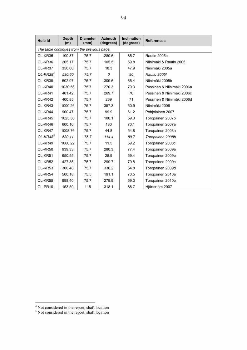
94
Hole id Depth
(m) Diameter
(mm) Azimuth
(degrees) Inclination (degrees)
References
The table continues from the previous page.
OL-KR35 100.87 75.7 280.6 85.7 Rautio 2005e
OL-KR36 205.17 75.7 105.5 59.8 Niinimäki & Rautio 2005
OL-KR37 350.00 75.7 18.3 47.9 Niinimäki 2005a
OL-KR384 530.60 75.7 0 90 Rautio 2005f
OL-KR39 502.97 75.7 309.6 65.4 Niinimäki 2005b
OL-KR40 1030.56 75.7 270.3 70.3 Pussinen & Niinimäki 2006a
OL-KR41 401.42 75.7 269.7 70 Pussinen & Niinimäki 2006c
OL-KR42 400.85 75.7 269 71 Pussinen & Niinimäki 2006d
OL-KR43 1000.26 75.7 357.3 60.9 Niinimäki 2006
OL-KR44 900.47 75.7 99.9 61.2 Pohjolainen 2007
OL-KR45 1023.30 75.7 100.1 59.3 Toropainen 2007b
OL-KR46 600.10 75.7 180 70.1 Toropainen 2007a
OL-KR47 1008.76 75.7 44.8 54.8 Toropainen 2008a
OL-KR485 530.11 75.7 114.4 89.7 Toropainen 2008b
OL-KR49 1060.22 75.7 11.5 59.2 Toropainen 2008c
OL-KR50 939.33 75.7 280.3 77.4 Toropainen 2009a
OL-KR51 650.55 75.7 28.9 59.4 Toropainen 2009b
OL-KR52 427.35 75.7 299.7 79.8 Toropainen 2009c
OL-KR53 300.48 75.7 330.2 54.8 Toropainen 2009d
OL-KR54 500.18 75.5 191.1 70.5 Toropainen 2010a
OL-KR55 998.40 75.7 279.9 59.3 Toropainen 2010b
OL-PR10 153.50 115 318.1 88.7 Hjärtsrtöm 2007
4 Not considered in the report, shaft location 5 Not considered in the report, shaft location

95
APPENDIX B: BACKFILL OPTIONS FOR UNDERGROUND DISPOSAL FACILITY CLOSURE
B1. Central tunnel backfill options: Comparison of hydraulic conductivities Table B-1 provides a summary of the expected hydraulic conductivity of a range of potential components of the central tunnel backfill under underground water salinity in the range of 3.5% to 7% TDS. The basic concept for backfilling the central tunnels, central tunnel connections and vehicle connections, which form the majority of the volume, is to be filled with precompacted Friedland clay blocks. The blocks are installed on a prepared clay-based foundation bed material (clay-only or clay-aggregate composition). After that the remaining gaps (tunnel wall-block gap and tunnel crown regions above the block-filled volume) are filled with pellets made from bentonite-clay (see Figure 3-2). The backfill must be capable of maintaining a long-term hydraulic conductivity of lower than 1 E-9 m/s. Therefore the backfill design is based on providing a one-order of magnitude margin to this value so as to accommodate any slight variations in the as-placed backfill density, composition, or variations in the degree of over-excavation that occurs during tunnel construction. The reference initial state for the deposition tunnel backfill provides some general guidelines with respect to achievable clay-block, in situ compacted and pellet-fill. (Hansen et al. 2009. Table 9-2). These densities provide the base-case for the central tunnel backfill components. However, given that the backfill in these tunnels are only expected to maintain a K = 1 E-9 m/s (or 1 E-10 m/s with margin). Several variations of composition and density were examined and these are summarised below. Friedland clay is the reference clay to be used in deposition tunnel backfill block manufacture. Being a natural material, there will need to have a quality control process associated with its procurement and subsequent block manufacture. For comparison purposes two variations in quality were evaluated (30% and 40% smectite content in the Friedland material). Additionally, consideration of the effects of lowering the density requirements for the blocks as well as using in situ compacted bentonite-aggregate mixtures as foundation bed materials were also evaluated. Table B-1 shows that there is a wide range of potentially hydraulically suitable backfill compositions that will provide the backfill with the desired one-order-of-magnitude margin in its hydraulic performance. In many cases the hydraulic conductivity at the time of installation of the pellet fill is not a full order of magnitude less permeable than the 1 E-9 m/s required, but it reached it during saturation. Evaluation of the density increase required for the pellet fill to reach its intended density requires approximately 10% higher density than at the time of installation. This is readily accomplished by the swelling of the adjacent Friedland clay blocks (volume increase in block-filled volume 0.8-2.5% depending on over-excavation degree). The most conservative condition shown in Table B-1 is where consolidation of pellets to EMDD of 875 kg/m3 (K=1 E-10 m/s) is achieved by swelling of low density (1800 kg/m3) block materials occurs under groundwater salinity conditions of 3.5% to 7% TDS. In this case, the swelled block-filled region will have a K< 5E-11 m/s. All other cases involving block and pellet constructions are more conservative than this, particularly if groundwater is less saline. On achieving the density required for K=1 E-10 m/s, the block fill still has swelling pressures that range from ~250 to 7,000 kPa above that of the pellet fill. This means that the system will ultimately evolve to a condition where the K is much lower than 1 E-10 m/s and will maintain contact pressures between all of the components.

96
Tab
le B
-1.
Com
pari
son
of h
ydra
ulic
con
duct
ivit
ies
of p
oten
tial
cen
tral
tunn
el b
ackf
ill c
ompo
nent
s. B
ased
on
dim
ensi
ons
prov
ided
in
Fig
ure
B-1
.
C
lay
Sm
ecti
te
Co
nte
nt
%
Mat
eria
l C
om
po
nen
t V
olu
me
m3/m
Dry
D
ensi
ty
kg/m
3
Inst
alle
d
Den
sity
kg
/m3*
Inst
alle
d
EM
DD
kg
/m3*
Est
imat
ed
Co
mp
on
ent
K (
m/s
)
Sw
ellin
g
Pre
ssu
re
PS
(kP
a**)
N
ote
s
Usi
ng
Fri
edla
nd
Cla
y: 3
0% S
mec
tite
Co
nte
nt
(Id
eal
cen
tral
tu
nn
el,
no
ove
r ex
cava
tio
n, c
ross
sec
tio
n 3
9.57
m2)
Frie
dla
nd
30
bloc
ks
35.4
9
1,95
0
1,92
3
1,15
1
5.E
-12
1,
500
m
eets
initi
al s
tate
++
Frie
dla
nd
30
bloc
ks
35.4
9
1,80
0
1,77
5
987
3.
E-1
1
600
m
eets
initi
al s
tate
++
Ben
ton
ite (
pelle
ts)
75
foun
d. b
ed
1.5
1,
200
1,
200
1,
015
3.
E-1
1
800
m
eets
initi
al s
tate
40-6
0 be
nton
ite-r
ock
75
foun
d. b
ed
1.5
1,
750
1,
750
98
3
5.E
-11
60
0
mee
ts in
itial
sta
te
30-7
0 be
nton
ite-r
ock
75
foun
d. b
ed
1.5
1,
750
1,
750
81
7
4.E
-10
20
0+
ma
y b
e su
itabl
e
Ben
ton
ite
75
pelle
ts1
2.58
95
0
950
78
3
4.E
-10
10
0+
-
Ben
ton
ite
75
pelle
ts1
2.58
1,
000
1,
000
82
8
3.E
-10
12
5+
-
Ben
ton
ite
75
pelle
ts
2.58
1,
050
1,
050
87
4
1.E
-10
37
0
mee
ts in
itial
sta
te
Usi
ng
Fri
edla
nd
Cla
y:
40%
Sm
ecti
te
(Id
eal
cen
tral
tu
nn
el,
no
ove
r ex
cava
tio
n,
cro
ss s
ect
ion
39.
57m
2)
Frie
dla
nd
40
bloc
ks
35.4
9
2,05
0
2,02
2
1,47
5
4.E
-13
8,
000
m
eets
initi
al s
tate
++
Frie
dla
nd
40
bloc
ks
35.4
9
1,95
0
1,92
3
1,34
8
7.E
-13
4,
000
m
eets
initi
al s
tate
++
Frie
dla
nd
40
bloc
ks
35.4
9
1,80
0
1,77
5
1,17
6
3.E
-12
1,
800
m
eets
initi
al s
tate
++
Ben
ton
ite (
pelle
ts)
75
foun
d. b
ed
1.5
1,
200
1,
200
1,
015
2.
E-1
1
800
m
eets
initi
al s
tate
++
40-6
0 be
nton
ite-r
ock
75
fo
und.
bed
1.
5
1,75
0
1,75
0
983
5.
E-1
1
600
m
eets
initi
al s
tate
++
30-7
0 be
nton
ite-r
ock
75
fo
und.
bed
1.
5
1,75
0
1,75
0
817
4.
E-1
0
200
m
ay
be
suita
ble
Ben
ton
ite
75
pelle
ts1
2.58
95
0
950
78
3
4.E
-10
10
0
-
Ben
ton
ite
75
pelle
ts1
2.58
1,
000
1,
000
82
8
3.E
-10
12
5
-
Ben
ton
ite
75
pelle
ts
2.58
1,
050
1,
050
87
4
1.E
-10
37
0
mee
ts in
itial
sta
te+
+

97
C
lay
Sm
ecti
te
Co
nte
nt
%
Mat
eria
l C
om
po
nen
t V
olu
me
m3
/ m
Dry
D
ensi
ty
kg/m
3
Inst
alle
d
Den
sity
kg
/m3*
Inst
alle
d
EM
DD
kg
/m3*
Est
imat
ed
Co
mp
on
ent
K (
m/s
)
Sw
ellin
g
Pre
ssu
re
PS
(kP
a**)
N
ote
s
Fri
edla
nd
Cla
y 30
% S
mec
tite
Frie
dla
nd
30
bloc
ks
35.4
9
2,05
0
2,02
2
1,27
6
1.E
-12
3,
000
m
eets
initi
al s
tate
++
Frie
dla
nd
30
bloc
ks
35.4
9
1,95
0
1,92
3
1,15
1
5.E
-12
1,
500
m
eets
initi
al s
tate
++
Frie
dla
nd
30
bloc
ks
35.4
9
1,80
0
1,77
5
987
3.
E-1
1
600
m
eets
initi
al s
tate
++
Ben
ton
ite (
pelle
ts)
75
foun
d. b
ed
3.47
1,
200
1,
200
1,
015
3.
E-1
1
800
m
eets
initi
al s
tate
40-6
0 be
nton
ite-r
ock
75
fo
und.
bed
3.
47
1,75
0
1,75
0
983
5.
E-1
1
600
m
eets
initi
al s
tate
30-7
0 be
nton
ite-r
ock
75
fo
und.
bed
3.
47
1,75
0
1,75
0
817
4.
E-1
0
200
m
ay
be
suita
ble
bent
oni
te
75
pelle
ts1
6.14
95
0
950
78
3
4.E
-10
10
0
-
bent
oni
te
75
pelle
ts1
6.14
1,
000
1,
000
82
8
3.E
-10
12
5
-
bent
oni
te
75
pelle
ts
6.14
1,
050
1,
050
87
4
1.E
-10
37
0
mee
ts in
itial
sta
te
Fri
edla
nd
Cla
y 40
% S
mec
tite
Frie
dla
nd
40
bloc
ks
35.4
9
2,05
0
2,02
2
1,47
5
2.E
-13
8,
000
m
eets
initi
al s
tate
++
Frie
dla
nd
40
bloc
ks
35.4
9
1,95
0
1,92
3
1,34
8
7.E
-13
4,
000
m
eets
initi
al s
tate
++
Frie
dla
nd
40
bloc
ks
35.4
9
1,80
0
1,77
5
1,17
6
8.E
-12
1,
800
m
eets
initi
al s
tate
++
Ben
ton
ite (
pelle
ts)
75
foun
d. b
ed
3.47
1,
200
1,
200
1,
015
2.
E-1
1
800
m
eets
initi
al s
tate
40-6
0 be
nton
ite-r
ock
75
fo
und.
bed
3.
47
1,75
0
1,75
0
983
5.
E-1
1
600
m
eets
initi
al s
tate
30-7
0 be
nton
ite-r
ock
75
fo
und.
bed
3.
47
1,75
0
1,75
0
817
4.
E-1
0
200
m
ay
be
suita
ble
bent
oni
te
75
pelle
ts1
6.14
95
0
950
78
3
4.E
-10
20
0
-
bent
oni
te
75
pelle
ts1
6.14
1,
000
1,
000
82
8
3.E
-10
12
5
-
bent
oni
te
75
pelle
ts
6.14
1,
050
1,
050
87
4
1.E
-10
37
0
mee
ts in
itial
sta
te

98
C
lay
Sm
ecti
te
Co
nte
nt
%
Mat
eria
l C
om
po
nen
t V
olu
me
m3
/ m
Dry
D
ensi
ty
kg/m
3
Inst
alle
d
Den
sity
kg
/m3*
Inst
alle
d
EM
DD
kg
/m3*
Est
imat
ed
Co
mp
on
ent
K (
m/s
)
Sw
ellin
g
Pre
ssu
re
PS
(kP
a**)
N
ote
s
Fri
edla
nd
Cla
y 30
% S
mec
tite
Frie
dla
nd
30
bloc
ks
35.4
9
2,05
0
2,02
2
1,27
6
1.E
-12
3,
000
m
eets
initi
al s
tate
++
Frie
dla
nd
30
bloc
ks
35.4
9
1,95
0
1,92
3
1,15
1
5.E
-12
1,
500
m
eets
initi
al s
tate
++
Frie
dla
nd
30
bloc
ks
35.4
9
1,80
0
1,77
5
987
3.
E-1
1
600
m
eets
initi
al s
tate
++
Ben
ton
ite (
pelle
ts)
75
foun
d. b
ed
5.66
1,
200
1,
200
1,
015
3.
E-1
1
800
m
eets
initi
al s
tate
40-6
0 be
nton
ite-r
ock
75
fo
und.
bed
5.
66
1,75
0
1,75
0
983
5.
E-1
1
600
m
eets
initi
al s
tate
30-7
0 be
nton
ite-r
ock
75
fo
und.
bed
5.
66
1,75
0
1,75
0
817
4.
E-1
0
200
m
ay
be
suita
ble
bent
oni
te
75
pelle
ts1
9.84
95
0
950
78
3
4.E
-10
10
0
bent
oni
te
75
pelle
ts1
9.84
1,
000
1,
000
82
8
3.E
-10
12
5
bent
oni
te
75
pelle
ts
9.84
1,
050
1,
050
87
4
1.E
-10
37
0
mee
ts in
itial
sta
te
Fri
edla
nd
ha
vin
g 4
0% S
mec
tite
Frie
dla
nd
40
bloc
ks
35.4
9
2,05
0
2,02
2
1,47
5
2.E
-13
8,
000
m
eets
initi
al s
tate
++
Frie
dla
nd
40
bloc
ks
35.4
9
1,95
0
1,92
3
1,34
8
7.E
-13
4,
000
m
eets
initi
al s
tate
++
Frie
dla
nd
40
bloc
ks
35.4
9
1,80
0
1,77
5
1,17
6
8.E
-12
18
00
m
eets
initi
al s
tate
++
Ben
ton
ite (
pelle
ts)
75
foun
d. b
ed
5.66
1,
200
1,
200
1,
015
2.
E-1
1
800
m
eets
t in
itial
sta
te
40-6
0 be
nton
ite-r
ock
75
foun
d. b
ed
5.66
1,
750
1,
750
98
3
5.E
-11
60
0
mee
ts in
itial
sta
te
30-7
0 be
nton
ite-r
ock
75
fo
und.
bed
5.
66
1,75
0
1,75
0
817
4.
E-1
0
200
m
ay
be
suita
ble
bent
oni
te
75
pelle
ts1
9.84
95
0
950
78
3
4.E
-10
10
0
bent
oni
te
75
pelle
ts1
9.84
1,
000
1,
000
82
8
3.E
-10
12
5
bent
oni
te
75
pelle
ts
9.84
1,
050
1,
050
87
4
1.E
-10
37
0
mee
ts in
itial
sta
te
* as
sum
ing
rou
gh e
stim
atio
n of
1.4
% v
olum
e of
join
ts b
etw
een
bloc
ks.
** a
ccou
ntin
g fo
r 1.
4% jo
int v
olum
e bu
t not
allo
win
g fo
r an
y vo
lum
e st
rain
by
inst
alle
d co
mpo
nent
s.
pelle
ts1 : L
ow
de
nsity
of
as-p
lace
d pe
llets
is im
prov
ed b
y co
mpr
essi
on b
y cl
ay-
bloc
k m
ater
ials
of h
ighe
r E
MD
D (
high
er s
wel
ling
pres
sure
).
++P
elle
ts r
equi
re ~
9-1
0% c
omp
ress
ion
in o
rder
to r
each
K o
f 10
-10 m
/s. T
his
corr
espo
nds
to a
0.7
- 2
.5%
exp
ansi
on o
f cl
ay-b
lock
s.

99
Figure B-1. Examples of the cross sections of the closure backfill.
100
B-2. Materials for use in backfilling access tunnels and shafts using in situ techniques and clay-aggregate mixtures. In regions beyond the central tunnels and below geological feature HZ20 and then between HZ20 and approximately the -200 m level, the underground disposal facility is to be backfilled using in situ compaction and clay-aggregate mixtures (Table 5-1). These regions are required to have a K of < 1E-8 m/s, and using the same safety margin approach used to define the backfill for the central tunnels, this backfill will need to have a K of < 1E-9 m/s (Table 5-1). Experience with in situ compaction of bentonite clay-aggregate materials have proved that the achieved dry densities are approximately 1,700 to 1,800 kg/m3 for 40-60 mixtures of bentonite and aggregate and similar (or higher) dry densities could be anticipated for 30-70 mixtures. Using these values for potential initial state K conditions a series of estimates have been produced using the data presented in Figure 3-5. For the region between the repository level and HZ20 it is assumed that saline conditions could develop and so estimates for K under fresh and saline groundwater conditions have been provided in Table B-2 as well as estimations of swelling pressures in saline groundwater conditions. Above HZ20 and below -200 m level where in situ clay-aggregate is to be installed it is assumed that essentially fresh water conditions will persist and Table B-3 provides estimates of the K values and swelling pressures that could be developed by bentonite-aggregate mixture. Saline groundwater conditions will limit the range of materials that will meet the required K for the in-situ backfilled material (Table B-2). Freshwater conditions will allow for a much greater range of material compositions and clay-types to be utilised (Table B-3). In estimating K and swelling pressure for potential materials it should be kept in mind that EMDD is limited to materials with more than 25% smectite content. Therefore Table B-4 provides a collection of K-values and swelling pressures measured for 30-70 and 40-60 mixtures in saline and distilled water (or tap water) for comparison.
101
Tab
le B
-2.
Ave
rage
hyd
raul
ic p
rope
rtie
s of
cla
y-ag
greg
ate
mix
ture
s pr
opos
ed f
or u
se i
n ac
cess
tun
nel
and
shaf
ts b
elow
HZ
20.
Req
uire
d K
< 1
E-8
m/s
und
er s
alin
e co
ndit
ions
. F
or c
onse
rvat
ive
reas
ons
K-v
alue
s sh
ould
be
< 1
E-9
m/s
(D
ixon
et
al.
2012
). D
ry d
ensi
ty s
et
acco
rdin
g to
ach
ieva
ble
in-s
itu
com
pact
ion
resu
lts
and
smec
tite
per
cent
age
set
acco
rdin
g to
ave
rage
ben
toni
te s
mec
tite
con
tent
s (D
ixon
et
al. 2
012)
.
Sm
ecti
te in
cl
ay
(%)
Cla
y-ag
gre
gat
e ra
tio
D
ry d
ensi
ty
(kg
/m3)
EM
DD
* o
f b
ackf
ill
(kg
/m3)
K in
dis
tille
d w
ater
(e
stim
ated
) (m
/s)
K**
in 3
.7–7
% T
DS
wat
er
(est
imat
ed)
(m/s
) S
wel
ling
pre
ssu
re**
(e
stim
ated
) (k
Pa)
75
30-7
0
1,70
0
739
***
4.00
E-1
2
2.00
E-1
0
<10
0
75
30-7
0
1,80
0
861
***
1.50
E-1
2
4.00
E-1
1
<20
0
75
40-6
0
1,70
0
902
2.
00E
-12
3.
00E
-11
20
0-30
0
75
40-6
0
1,80
0
1,03
6
1.00
E-1
2
1.00
E-1
1
600-
700
*G
rain
de
nsity
est
imat
ed a
ccor
ding
to b
alla
st g
rain
de
nsity
2,7
00 k
g/m
3 (
Ket
o et
al.
200
9) a
nd b
ent
onite
gra
in d
ensi
ty 2
,800
kg/
m3,
wh
ich
is e
stim
atio
n be
twe
en A
C20
0 (K
eto
et a
l. 20
09)
and
IBE
CO
RW
C (
Kiv
irant
a &
Kum
pula
inen
20
11).
**
Est
imat
ions
acc
ord
ing
to E
MD
D (
Fig
ure
3-5
and
Dix
on e
t al.
2011
a, F
igur
e 3-
3).
***
Sm
ectit
e co
nten
t < 2
5%, r
esul
ts s
hou
ld b
e o
btai
ned
by
othe
r m
eans
, i.e
. lab
orat
ory
inve
stig
atio
ns (
Tab
le B
-4).
102
Tab
le B
-3.
Ave
rage
hyd
raul
ic p
rope
rtie
s of
cla
y-ag
greg
ate
mix
ture
s pr
opos
ed f
or u
se i
n ac
cess
tun
nels
and
sha
fts
betw
een
HZ
20 a
nd -
200
m d
epth
s. K
< 1
E-8
m/s
und
er f
resh
wat
er c
ondi
tion
s. F
or c
onse
rvat
ive
reas
ons
K-v
alue
s sh
ould
be
< 1
E-9
m/s
(D
ixon
et
al.
2012
).
Dry
den
sity
set
acc
ordi
ng t
o ac
hiev
able
in-
situ
com
pact
ion
resu
lts
and
smec
tite
per
cent
age
set
acco
rdin
g to
ave
rage
ben
toni
te s
mec
tite
co
nten
ts (
Dix
on e
t al.
2012
).
Sm
ecti
te in
cla
y (%
) C
lay-
agg
reg
ate
rati
o
Dry
den
sity
(k
g/m
3)
EM
DD
* o
f b
ackf
ill (
kg/m
3 ) K
** in
dis
tille
d w
ater
(e
stim
ated
) (m
/s)
Sw
ellin
g p
ress
ure
** (
esti
ma
ted
) (k
Pa)
75
30-7
0
1,70
0
739
***
4.00
E-1
2
~20
0
75
30-7
0
1,80
0
861
***
1.50
E-1
2
<40
0
75
40-6
0
1,70
0
902
2.
00E
-12
<
500
75
40-6
0
1,80
0
1,03
6
1.00
E-1
2
<90
0
* G
rain
de
nsity
est
imat
ed a
ccor
ding
to b
alla
st g
rain
de
nsity
2,7
00 k
g/m
3 (
Ket
o et
al.
200
9) a
nd b
ent
onite
gra
in d
ensi
ty 2
,800
kg/
m3,
wh
ich
is e
stim
atio
n be
twe
en A
C20
0 (K
eto
et a
l. 20
09)
and
IBE
CO
RW
C (
Kiv
irant
a &
Kum
pula
inen
20
11).
**
Est
imat
ions
acc
ord
ing
to E
MD
D (
Fig
ure
3-5
and
Dix
on e
t al.
2011
a, F
igur
e 3-
3).
***
Sm
ectit
e co
nten
t < 2
5%, r
esul
ts s
hou
ld b
e o
btai
ned
by
othe
r m
eans
(e.
g. l
abor
ator
y in
vest
igat
ions
, Tab
le B
-4).

103
Table B-4. Hydraulic conductivity (K) and swelling pressure for 30-70 and 40-60 mixtures of bentonite and aggregate, respectively, in saline and distilled water (or tap water). Mixture refers to swelling clay-aggregate ratio.
Reference Bentonite Mixture Dry
density (kg/m3)
Water type
(salinity %)
K-value (m/s)
Swelling pressure
(kPa)
Keto et al. (2006)
Deponit CAN 30/70 1,860 3.5% 8E-11 1,920
Deponit CAN 30/70 1,883 3.5% <1.00E-11 1,930
Johannesson & Nilsson (2006)
MX-80 30/70 1,711 3.5% 1.20E-06 150
MX-80 30/70 1,739 7 % 1.14E-07 140
Deponit CA-N 30/70 1,753 3.5% 8.62E-11 200
Deponit CA-N 30/70 1,775 7 % 1.40E-11 185
MX-80 30/70 1,777 7 % 3.74E-07 200
MX-80 30/70 1,782 3.5% 4.59E-07 180
Deponit CA-N 30/70 1,798 3.5% 2.41E-11 270
Deponit CA-N 30/70 1,816 3.5% 3.37E-10 150
Deponit CA-N 30/70 1,819 7 % 7.30E-10 140
Deponit CA-N 30/70 1,820 3.5% 1.47E-11 270
Deponit CA-N 30/70 1,827 7 % 2.63E-11 312
Deponit CA-N 30/70 1,827 3.5% 2.98E-11 450
MX-80 30/70 1,830 3.5% 8.04E-09 430
Deponit CA-N 30/70 1,847 3.5% 1.80E-10 180
Deponit CA-N 30/70 1,850 7 % 2.69E-11 450
Deponit CA-N 30/70 1,853 3.5% 1.47E-11 495
MX-80 30/70 1,857 7 % 9.70E-10 350
Deponit CA-N 30/70 1,859 7 % 8.06E-11 300
Deponit CA-N 30/70 1,859 3.5% 3.52E-11 1000
Deponit CA-N 30/70 1,862 3.5% 5.30E-11 430
Deponit CA-N 30/70 1,863 7 % 1.58E-11 465
MX-80 30/70 1,866 7 % 6.62E-11 1,120
Deponit CA-N 30/70 1,872 7 % 1.74E-10 200
Deponit CA-N 30/70 1,884 7 % 1.75E-11 610
Deponit CA-N 30/70 1,889 3.5% 1.19E-11 765
Deponit CA-N 30/70 1,893 3.5% 2.24E-11 540
Deponit CA-N 30/70 1,893 3.5% 1.26E-11 460
Deponit CA-N 30/70 1,894 7 % 4.60E-11 350
Deponit CA-N 30/70 1,899 7 % 2.67E-11 350
Deponit CA-N 30/70 1,901 7 % 1.09E-11 790
The table continues on the next page.
104
The table continues from the previous page.
Reference Bentonite Mixture Dry
density (kg/m3)
Water type
(salinity %)
K-value (m/s)
Swelling pressure
(kPa)
Johannesson & Nilsson (2006)
MX-80 30/70 1,911 7 % 1.32E-09 1,930
MX-80 30/70 1,915 3.5% 4.23E-11 1,280
Deponit CA-N 30/70 1,915 7 % 1.52E-11 500
MX-80 30/70 1,921 7 % 1.63E-11 1,500
MX-80 30/70 1,924 3.5% 7.87E-11 1,170
MX-80 30/70 1,994 3.5% 4.50E-12 2,040
Johannesson (2008)
Deponit CA-N 30/70 1,910 3,5 % 3.00E-11 700
Deponit CA-N 30/70 1,910 7,0 % 3.00E-11 500
Johannesson & Nilsson (2006)
Deponit CA-N 40/60 1,766 3.5% 2.35E-11 290
Deponit CA-N 40/60 1,788 7 % 2.32E-11 320
Deponit CA-N 40/60 1,822 3.5% 9.58E-12 635
Deponit CA-N 40/60 1,846 7 % 1.21E-11 515
Deponit CA-N 40/60 1,875 3.5% 8.54E-12 765
Deponit CA-N 40/60 1,880 7 % 7.10E-12 765
Schatz & Martikainen (2012)
IBECO 40/60 1,531 3.5% 3.90E-09 1,252
AC200 40/60 1,563 3.5% 7.60E-11 267
AC200 40/60 1,580 3.5% 7.30E-11 367
IBECO 40/60 1,586 3.5% 3.70E-10 638
AC200 40/60 1,626 3.5% 6.30E-11 375
Johannesson & Nilsson (2006)
MX-80 30/70 1,726 Distilled 1.04E-11 120
Deponit CA-N 30/70 1,789 Distilled 2.00E-12 420
Deponit CA-N 30/70 1,704 Distilled 7.06E-11 120
Deponit CA-N 30/70 1,718 Distilled 4.46E-11 160
Deponit CA-N 30/70 1,718 Distilled 5.09E-11 270
Deponit CA-N 40/60 1,771 Distilled 1.18E-11 420
Schatz & Martikainen (2012)
AC200 30/70 1,541 Tap
water 2.70E-11 140
AC200 30/70 1,636 Tap
water 2.90E-11 230
AC200 40/60 1,474 Tap
water 1.1E-11 260
AC200 40/60 1,628 Tap
water 3.70E-12 860

LIST OF REPORTS
POSIVA-REPORTS 2012
_______________________________________________________________________________________
POSIVA 2012-01 Monitoring at Olkiluoto – a Programme for the Period Before Repository Operation Posiva Oy ISBN 978-951-652-182-7 POSIVA 2012-02 Microstructure, Porosity and Mineralogy Around Fractures in Olkiluoto
Bedrock Jukka Kuva (ed.), Markko Myllys, Jussi Timonen, University of Jyväskylä Maarit Kelokaski, Marja Siitari-Kauppi, Jussi Ikonen, University of Helsinki Antero Lindberg, Geological Survey of Finland Ismo Aaltonen, Posiva Oy ISBN 978-951-652-183-4
POSIVA 2012-03 Safety Case for the Disposal of Spent Nuclear Fuel at Olkiluoto - Design Basis 2012 ISBN 978-951-652-184-1 POSIVA 2012-04 Safety Case for the Disposal of Spent Nuclear Fuel at Olkiluoto - Performance Assessment 2012 ISBN 978-951-652-185-8 POSIVA 2012-05 Safety Case for the Disposal of Spent Nuclear Fuel at Olkiluoto - Description of the Disposal System 2012 ISBN 978-951-652-186-5 POSIVA 2012-06 Olkiluoto Biosphere Description 2012 ISBN 978-951-652-187-2 POSIVA 2012-07 Safety Case for the Disposal of Spent Nuclear Fuel at Olkiluoto - Features, Events and Processes 2012 ISBN 978-951-652-188-9 POSIVA 2012-08 Safety Case for the Disposal of Spent Nuclear Fuel at Olkiluoto - Formulation of Radionuclide Release Scenarios 2012 ISBN 978-951-652-189-6 POSIVA 2012-09 Safety Case for the Disposal of Spent Nuclear Fuel at Olkiluoto - Assessment of Radionuclide Release Scenarios for the Repository System 2012 ISBN 978-951-652-190-2

POSIVA 2012-10 Safety case for the Spent Nuclear Fuel Disposal at Olkiluoto - Biosphere Assessment BSA-2012 ISBN 978-951-652-191-9 POSIVA 2012-11 Safety Case for the Disposal of Spent Nuclear Fuel at Olkiluoto - Complementary Considerations 2012 Posiva Oy ISBN 978-951-652-192-6 POSIVA 2012-12 Safety Case for the Disposal of Spent Nuclear Fuel at Olkiluoto - Synthesis 2012 Posiva Oy ISBN 978-951-652-193-3 POSIVA 2012-13 Canister Design 2012 Heikki Raiko, VTT ISBN 978-951-652-194-0 POSIVA 2012-14 Buffer Design 2012 Markku Juvankoski ISBN 978-951-652-195-7 POSIVA 2012-15 Backfill Design 2012 ISBN 978-951-652-196-4 POSIVA 2012-16 Canister Production Line 2012 – Design, Production and Initial State of the Canister Heikki Raiko (ed.), VTT Barbara Pastina, Saanio & Riekkola Oy Tiina Jalonen, Leena Nolvi, Jorma Pitkänen & Timo Salonen, Posiva Oy ISBN 978-951-652-197-1 POSIVA 2012-17 Buffer Production Line 2012 – Design, Production, and Initial State of the Buffer Markku Juvankoski, Kari Ikonen, VTT Tiina Jalonen, Posiva Oy ISBN 978-951-652-198-8 POSIVA 2012-18 Backfill Production Line 2012 - Design, Production and Initial State of the Deposition Tunnel Backfill and Plug ISBN 978-951-652-199-5 POSIVA 2012-19 Closure Production Line 2012 - Design, Production and Initial State of Underground Disposal Facility Closure ISBN 978-951-652-200-8