design presentation dp 001 general requirements presentation – construction drawings dp 001 –...
TRANSCRIPT

Safety And Service Division
ROAD/RAIL DESIGN Standards & Guidelines
Design Presentation – Construction Drawings
DP 001 – General Requirements
K-Net Doc: 3743988 UNCONTROLLED COPY WHEN PRINTED Version No.: 12 Issue Date: 10/08/2017 Doc. Owner: Principal Road Design Engineer Page 1 of 26
Purpose and Scope In South Australia the Department of Planning, Transport and Infrastructure (DPTI) is responsible for the construction, management and maintenance of the state’s major road, light rail and heavy rail infrastructure. Construction Drawings are used for all three of these phases. This document describes standards and procedures that are to be adopted in the production of these Construction Drawings. The aim is to provide a sound basis for the production of consistent, high quality drawings that facilitate construction and can be easily stored and accessed in accordance with Departmental requirements. The provisions of this document apply to DPTI staff and all external organisations when producing Rail or Road Design Construction Drawings for DPTI. This document along with other Road Design Standards and Guidelines are accessible from http://www.dpti.sa.gov.au/standards Associated CAD Support Files including the DPTI Layer Matrix are accessible from ftp.transportsa.com.au

Design Presentation - Construction Drawings DP 001 – General Requirements
K-Net Doc: 3743988 UNCONTROLLED COPY WHEN PRINTED Version No.: 12 Issue Date: 10/08/2017 Doc. Owner: Principal Road Design Engineer Page 2 of 26
This page has been left blank intentionally

Design Presentation - Construction Drawings DP 001 – General Requirements
K-Net Doc: 3743988 UNCONTROLLED COPY WHEN PRINTED Version No.: 12 Issue Date: 10/08/2017 Doc. Owner: Principal Road Design Engineer Page 3 of 26
Document Control
DOCUMENT STATUS
Document Owner: Principal Road Design Engineer, Planning & Design, DTEI
Action Name and Position Date
Prepared By: John Hastie, CAD Manager 10 July 2009
Reviewed By: Natasha Stone, Senior Road Designer 17 July 2009
Approved By: Noel O’Callaghan, Principal Road Design Engineer 24 July 2009
DOCUMENT AMENDMENT RECORD
Rev Change Description Date Prepared Reviewed Authorised
1 Initial Issue 29/07/2009 John Hastie Natasha Stone Noel O’Callaghan
2 Major update including modifications to incorporate rail requirements
25/05/2010 John Hastie Doug Gillott Noel O’Callaghan
3 Addition of revision bars in left margin to highlight changes made in revision 2
31/05/2010 Jillian Johnson John Hastie Jeff Lane
4
Numerous changes made where highlighted. Appendix A (DPTI Layer Matrix) removed from main body of document. Matrix Is now accessed by downloading the Excel file from the CAD Support Files area.
02/02/2012 John Hastie Natasha Stone Noel O’Callaghan
5 Minor changes on Page 1, 19 & 23 21/05/2012 John Hastie Jeremy Champion
deCrespigny Noel O’Callaghan
6 Changes to clauses 13,16,17,18 & 21 The changes to clause 18 are for clarity only rather than a change to the intent.
12/12/2012 John Hastie Jeremy Champion
deCrespigny Noel O’Callaghan
7 Changes to Clauses 13,14,20 & 21 31/10/2013 John Hastie Jeremy Champion
deCrespigny Noel O’Callaghan
8 Changes to Clauses 17.1 & 17.2 26/03/2014 John Hastie Jeremy Champion
deCrespigny Noel O’Callaghan
9 Changes to Clauses 10,20 & 21 15/06/2015 J Ch de C John Hastie Noel O’Callaghan
10 Multiple changes as highlighted 04/11/2016 John Hastie Paul Wingent Jeremy Champion
deCrespigny
11 1:1000 removed from list of preferred scales 21/12/2016 John Hastie Paul Wingent Jeremy Champion
deCrespigny
12 Preferred DWG version updated to 2013. Wording change in clause 13 table.
10/08/2017 John Hastie Paul Wingent Jeremy Champion
deCrespigny

Design Presentation - Construction Drawings DP 001 – General Requirements
K-Net Doc: 3743988 UNCONTROLLED COPY WHEN PRINTED Version No.: 12 Issue Date: 10/08/2017 Doc. Owner: Principal Road Design Engineer Page 4 of 26
Design Presentation - Construction Drawings DP 001 – General Requirements
K-Net Doc: 3743988 UNCONTROLLED COPY WHEN PRINTED Version No.: 12 Issue Date: 10/08/2017 Doc. Owner: Principal Road Design Engineer Page 5 of 26
This page has been left blank intentionally

Design Presentation - Construction Drawings DP 001 – General Requirements
K-Net Doc: 3743988 UNCONTROLLED COPY WHEN PRINTED Version No.: 12 Issue Date: 10/08/2017 Doc. Owner: Principal Road Design Engineer Page 6 of 26
Table of Contents Definitions ............................................................................................................................................... 8
DPTI ...................................................................................................................................................... 8 Construction Drawing ............................................................................................................................ 8 Plan Custodian ...................................................................................................................................... 8 Drawing Acceptance Form .................................................................................................................... 8 Acceptance ........................................................................................................................................... 8 IFC Drawings (Issued For Construction) ................................................................................................ 8 Project Sponsor ..................................................................................................................................... 8 KNET Number ....................................................................................................................................... 8 PATCHS Number .................................................................................................................................. 8 DPTI Design Manager ........................................................................................................................... 9 Project Survey Data Set ........................................................................................................................ 9 Local Grid .............................................................................................................................................. 9 MGA Planar .......................................................................................................................................... 9 Global Coordinate System..................................................................................................................... 9
1. Construction Drawing Types ................................................................................................... 10 2. Project Coordinate System ...................................................................................................... 10 3. Standard information to be shown on Construction Drawings ............................................. 11
3.1 Scale Bars .............................................................................................................................. 11 3.2 North Point .............................................................................................................................. 11 3.3 Matchlines, “For Continuation” and “Extent of Works” ............................................................. 11 3.4 Direction arrows ...................................................................................................................... 11 3.5 Road Names ........................................................................................................................... 11 3.6 General Notes ......................................................................................................................... 11 3.7 Vehicle Turning Paths ............................................................................................................. 12 3.8 Legends .................................................................................................................................. 12
4. Road Running Distance / Maintenance Markers ..................................................................... 12 4.1 Road Running Distance (RRD) ............................................................................................... 12 4.2 Maintenance Marker (MM) ...................................................................................................... 13
5. Removing Existing Drawing Components .............................................................................. 13 6. Drawing Size ............................................................................................................................. 13 7. Drawing Orientation .................................................................................................................. 13 8. Drawing Scales ......................................................................................................................... 13
8.1 Plan Drawings ......................................................................................................................... 14 8.2 Longitudinal Sections (Road or Drainage) ............................................................................... 14 8.3 Cross Sections ........................................................................................................................ 14 8.4 Details ..................................................................................................................................... 14
9. AutoCAD Template File ............................................................................................................ 14 10. Modifying Scanned Drawings .................................................................................................. 14 11. Model Space / Paper Space ...................................................................................................... 14
11.1 Model Space scale .................................................................................................................. 14 11.2 Paper Space scale .................................................................................................................. 15
12. Line Types ................................................................................................................................. 15 13. Line Colour and Lineweight ..................................................................................................... 15 14. Text ............................................................................................................................................ 17
14.1 Size ......................................................................................................................................... 17 14.2 Colour ..................................................................................................................................... 17 14.3 Case ....................................................................................................................................... 17 14.4 Fonts ....................................................................................................................................... 17 14.5 Width Factor / Angle ................................................................................................................ 17 14.6 Elevation ................................................................................................................................. 17 14.7 Paper Space / Model Space Text Heights ............................................................................... 17

Design Presentation - Construction Drawings DP 001 – General Requirements
K-Net Doc: 3743988 UNCONTROLLED COPY WHEN PRINTED Version No.: 12 Issue Date: 10/08/2017 Doc. Owner: Principal Road Design Engineer Page 7 of 26
15. Layer Naming ............................................................................................................................ 18 15.1 Feature Type codes ................................................................................................................ 18 15.2 Standard Layers ...................................................................................................................... 19 15.3 Subdividing Layers .................................................................................................................. 19 15.4 Creating New Layers ............................................................................................................... 19
16. Standard Block Library............................................................................................................. 19 17. Title Block ................................................................................................................................. 20
17.1 Road No(s). ............................................................................................................................ 20 17.2 Road Name / Rail Line Name .................................................................................................. 20 17.3 Project Location Description .................................................................................................... 20 17.4 Sheet Location Description ..................................................................................................... 20 17.5 Drawing Type .......................................................................................................................... 20 17.6 Designed /Checked ................................................................................................................. 20 17.7 Drafted / Checked ................................................................................................................... 20 17.8 Accepted For Use ................................................................................................................... 20 17.9 Acceptance Form KNet No. ..................................................................................................... 21 17.10 Drawing No. ........................................................................................................................ 21 17.11 Sheet No. ............................................................................................................................ 21 17.12 Amend No. .......................................................................................................................... 21 17.13 CAD File Name ................................................................................................................... 21 17.14 Signal No. ........................................................................................................................... 21 17.15 Project Number ................................................................................................................... 21 17.16 File Number ........................................................................................................................ 21 17.17 Design Number ................................................................................................................... 21 17.18 Survey Number ................................................................................................................... 21 17.19 Project Start RRD ................................................................................................................ 22 17.20 Project End RRD ................................................................................................................. 22 17.21 Scales ................................................................................................................................. 22 17.22 Consultant Logos and Approvals ......................................................................................... 22 17.23 Amendment Box .................................................................................................................. 22 17.24 Index Sheet Reference ........................................................................................................ 22 17.25 Project Document Reference .............................................................................................. 22 17.26 Sheet Latitude, Sheet Longitude ......................................................................................... 23
18. Drawing Amendments .............................................................................................................. 23 18.1 Official Amendments ............................................................................................................... 23 18.2 Unofficial Amendments ........................................................................................................... 23
19. Superseding Drawings ............................................................................................................. 24 20. Filenames .................................................................................................................................. 24
20.1 DWG Files .............................................................................................................................. 24 20.2 Individual PDF Files ................................................................................................................ 24
21. Drawing Transmittal Requirements ......................................................................................... 25 21.1 DWG Files .............................................................................................................................. 25 21.2 PDF Files ................................................................................................................................ 25 21.3 Drawing Details Spreadsheet .................................................................................................. 25
Appendix A – DPTI Layer Matrix .......................................................................................................... 26
Design Presentation - Construction Drawings DP 001 – General Requirements
K-Net Doc: 3743988 UNCONTROLLED COPY WHEN PRINTED Version No.: 12 Issue Date: 10/08/2017 Doc. Owner: Principal Road Design Engineer Page 8 of 26
Definitions
DPTI
Department of Planning, Transport and Infrastructure
Construction Drawing
Formally accepted DPTI drawings, created for the purpose of constructing and maintaining all aspects of road and rail infrastructure. Construction Drawings are registered with the Plan Custodian and are allocated an official Drawing number and Sheet number in accordance with DP013.
Plan Custodian
The Plan Custodian, Corporate Records Unit, is responsible for the storage, control & distribution of DPTI Drawings, and for ensuring compliance with Government records management legislation.
Drawing Acceptance Form
Means the DPTI form “Drawings Acceptance Form (Roads)” The completed Drawing Acceptance Form is stored in Knet and will generally have a completed “Request for Drawing / Sheet Registration Numbers” form attached.
Acceptance
The Project Sponsor is satisfied that the level of technical endorsement is appropriate and the final scoped project meets project objectives. This acceptance provides authorisation that the drawing(s) can be used for its intended purpose. Acceptance formally takes place when Part D of the Drawing Acceptance Form is signed.
IFC Drawings (Issued For Construction)
Drawings that represent a record of the design that was approved by DPTI and accepted in accordance with the above definition. These are the drawings that are issued to the constructor for the purpose of building the job.
Project Sponsor
An Executive or Senior Manager accountable for infrastructure project outcomes, who uses their authority to provide leadership and direction to the project and to ensure adequate project controls are in place.
KNET Number
The unique identifier assigned to a document in the DPTI Records Management System “KNET”
PATCHS Number
The 8 digit number assigned to a job in the Project Activity Tracking and Charging System (PATCHS)

Design Presentation - Construction Drawings DP 001 – General Requirements
K-Net Doc: 3743988 UNCONTROLLED COPY WHEN PRINTED Version No.: 12 Issue Date: 10/08/2017 Doc. Owner: Principal Road Design Engineer Page 9 of 26
DPTI Design Manager
This will be one of the following depending on the project:
Road Projects (in house) Design Manager, Planning & Design Section, DPTI
Road Projects (external) Design/Contract Manager, Consultant Management Unit, Planning & Design Section, DPTI
Landscape Projects Senior Landscape Architect, Specialist Services Section, DPTI
Rail Projects Program Director, Adelaide Rail Program, DPTI
Project Survey Data Set
The engineering survey data provided for a given project. Once created this data establishes the coordinate system that is to be used for that project.
Local Grid
The horizontal and vertical coordinates established by the Project Survey Data Set.
MGA Planar
A Local Grid where the coordinates closely match MGA coordinates This is generally established by picking a permanent survey mark close to the centre of the project area and assigning it the same coordinates that it would have in the relevant MGA zone.
Global Coordinate System
Location data for the project is to be referenced to the datum known as the Geocentric Datum of Australia (GDA) GDA is part of a global coordinate reference frame and is directly compatible with the Global Positioning System (GPS) The Projected coordinate system shall be either “GDA 1994 South Australian Lambert” or “GDA 1994 MGA” Within South Australia “GDA 1994 MGA” will be either zone 52, 53 or 54.

Design Presentation - Construction Drawings DP 001 – General Requirements
K-Net Doc: 3743988 UNCONTROLLED COPY WHEN PRINTED Version No.: 12 Issue Date: 10/08/2017 Doc. Owner: Principal Road Design Engineer Page 10 of 26
1. Construction Drawing Types
Below is a list of the standard types of Construction Drawings. Which drawing types are to be used on each project is to be decided by agreement with the DPTI Design Manager. For more detail about what information should be shown on each drawing type and how it should be drawn, refer to the relevant design presentation standard for that drawing type. Where practical sheet numbers should be allocated so that the sequence of drawings in the suite is the same as the list below.
Drawing Type Design Presentation Standard
Title and Index DP 002
General Construction DP 003
Vegetation Removal DP 004
Geometric Setout DP 005
Drainage DP 006
Drainage Catchment DP 007
Final Surface Contours DP 008
Pavement Treatment DP 009
Traffic Control DP 010
Traffic Signals DP 011
Traffic Signal Conduit DP 012
Lighting DP 013
Longitudinal Sections DP 014
Cross sections DP 015
Drainage Longitudinal Section DP 016
Landscape Design DP 017
Irrigation
Intelligent Transport Systems
2. Project Coordinate System It is critical that all survey and design work for a given project is carried out according to the same coordinate system. All drawings created as part of the project shall also use this same coordinate system. Prior to a Project Survey Data Set being issued, modelling work may be performed using the Global Coordinate System, however once a Project Survey Data Set has been issued, all design work shall be undertaken in accordance with the Local Grid established by that Project Survey Data Set. One of the following notes shall be included on the relevant geometric drawing to indicate which coordinate system being used:
Coordinate base is Local
Coordinate base is MGA Planar
Coordinate base is GDA 1994 MGA Zone 52
Coordinate base is GDA 1994 MGA Zone 53
Coordinate base is GDA 1994 MGA Zone 54
Coordinate base is GDA 1994 South Australia Lambert

Design Presentation - Construction Drawings DP 001 – General Requirements
K-Net Doc: 3743988 UNCONTROLLED COPY WHEN PRINTED Version No.: 12 Issue Date: 10/08/2017 Doc. Owner: Principal Road Design Engineer Page 11 of 26
3. Standard information to be shown on Construction Drawings
All drawings shall have sufficient detail to clearly and adequately explain what is required to those responsible for the construction. This is likely to include numerous small notes with leader lines to clarify specific details however care must also be taken not to clutter the drawing with unnecessary detail or obscure important information. Where there is doubt about whether a particular item should be included or whether the level of detail is sufficient, clarification should be sought from the DPTI Design Manager. The following specific information shall be shown where relevant.
3.1 Scale Bars
Shall be drawn in Paperspace on AutoCAD layer D-ENHA–Title Block.
3.2 North Point
North Points shall be shown on every plan drawing and shall be drawn in model space on AutoCAD layer D-ENHA–North Point.
3.3 Matchlines, “For Continuation” and “Extent of Works”
All drawings shall include matchlines to indicate the point at which the detail from another drawing sheet takes over. These matchlines shall include the words “FOR CONTINUATION SEE DRG XXXX SHEET XXXX” (where “xxxx” is the appropriate drawing and sheet number) or the words “EXTENT OF WORKS” where the current project does not extend onto an adjoining sheet. Matchlines shall be green, in Model Space on layer D-ENHA-Matchline Matchline text shall be green, 3.5mm high in Paper Space on layer D-ENHA-Matchline Landscape drawings may include a boundary line denoting the extent of the landscaping works. These extent of works boundaries and the associated text shall be in Model Space on layer D-LSCP-Extent of Works.
3.4 Direction arrows
Direction arrows shall be placed at the ends of each sheet to help show the project’s location. They should indicate the name of the next town on rural projects or the next major road or suburb on urban projects. Direction arrows shall be drawn in Modelspace, on layer D-ENHA-Direction Arrows. The arrows and text shall be drawn in green and the text shall have a Paper Space height of 3.5mm
3.5 Road Names
Road names are divided into two categories ‘Major’ and ‘Minor’ and are displayed above or on the left hand side of the road way. Road names shall be drawn in Model Space on layer D-ENHA–Road Names Major road names shall be drawn in blue with a Paper Space text height of 7.0mm Minor road names shall be drawn in red with a Paper Space text height of 5.0mm
3.6 General Notes
Standard sets of notes have been supplied by DPTI as AutoCAD blocks appropriate to the drawing type on which they are to appear. The appropriate notes are to be selected and modified to suit the project, notes that are not relevant to that project should not appear, however where a note is required on one sheet it shall appear on all sheets of that type.

Design Presentation - Construction Drawings DP 001 – General Requirements
K-Net Doc: 3743988 UNCONTROLLED COPY WHEN PRINTED Version No.: 12 Issue Date: 10/08/2017 Doc. Owner: Principal Road Design Engineer Page 12 of 26
This means for example that the notes on all the General Construction drawings on a given project should be identical and preferably in the same location on each sheet. Any additional General Notes that are not part of the standard notes in the DPTI block library shall be approved by the DPTI Design Manager before being included on the drawing. At times it may be necessary to show multiple sets of General Notes (eg a General Construction drawing may require both Geometric and Drainage notes). In these situations the notes shall be combined, duplications removed and the notes renumbered accordingly. Where there is insufficient room on a given sheet for the necessary notes, reference may be made to another sheet containing these notes. This may be either another sheet of that type in the suite which has the relevant notes on it, or it may be a dedicated ‘Notes sheet’. General Notes shall be drawn in paper space, on layer D-ENHA–General Notes
3.7 Vehicle Turning Paths
Where the road geometry on a particular sheet has been designed to cater for a particular vehicle or vehicles, then the relevant Traffic Control sheets shall include a note to indicate this. This note shall be the last note in the block and shall be separated from the other notes to draw attention to the fact that this particular note is sheet specific. (see Traffic control Example Drawing)
3.8 Legends
Standard legends have been supplied by DPTI as AutoCAD blocks appropriate to the drawing type on which they are to appear. The appropriate legend is to be selected and modified to suit the project. Items that are not relevant to that project should not appear on the legend, however where an item is required in the legend on one sheet it shall appear in the legend on all sheets of that type. This means for example that the legend on all the General Construction drawings on a given project should be identical and preferably in the same location on each sheet. Any additional legend symbols or definitions that are not part of the standard legends in the DPTI block library shall be approved by the DPTI Design Manager before being included on the drawing. At times it may be necessary to show legends of multiple types (eg a General Construction drawing may require both Lighting and Services legends). In these situations the legend items shall be combined and duplications removed. Where there is insufficient room on a given sheet for the necessary legend, reference may be made to another sheet containing the relevant items. This may be either another sheet of that type in the suite which has the relevant items on it, or it may be a dedicated ‘Legend sheet’. Legends shall be drawn in paper space, on layer D-ENHA–Legends
4. Road Running Distance / Maintenance Markers
It should be noted that the term “Road Running Distance” is not interchangeable with the term “Maintenance Marker”.
4.1 Road Running Distance (RRD)
Road Running Distance relates to the cumulative distance along a carriageway from the start of the road, it has significant implications for departmental databases and is strictly defined and controlled. RRD numbers must be allocated by the Transport Information Management Section of DPTI.

Design Presentation - Construction Drawings DP 001 – General Requirements
K-Net Doc: 3743988 UNCONTROLLED COPY WHEN PRINTED Version No.: 12 Issue Date: 10/08/2017 Doc. Owner: Principal Road Design Engineer Page 13 of 26
When staff from an external organisation need to know a RRD (for example to complete the titleblock) they should contact the DPTI Design manager. Where a Road Running Distance is shown it should be in the format RRD18.23
4.2 Maintenance Marker (MM)
A Maintenance Marker is a physical marker post located along the side of the road. Maintenance Marker numbers may or may not coincide with Road Running Distance numbers. Where Maintenance Markers are shown on a drawing they should be annotated with the marker number eg “Maintenance Marker 16”. Where a location is to be recorded in relation to a maintenance marker it should be shown as a distance in metres before or after that marker, for example “MM16+230m” or “MM23-15m”
5. Removing Existing Drawing Components
Drawings are commonly created using data from another source as a base (for example a road designer will create their drawings using data from survey as a base and a landscape designer will create their drawings using the road design drawing as a base) Where it is necessary to edit this source data, a copy should be made and the changes made to this copy rather than the original. For example it may be necessary to edit a survey Xref to remove the detail within the extents of the design. In this case a copy of the Xref should be made and the detail removed from this copy. This could be achieved within the design package used to produce the xref, or manually within a drafting package. In this way the original data remains intact and can be reloaded at any stage to check there are no discrepancies between the copies.
6. Drawing Size
All Drawings shall be A1 size.
7. Drawing Orientation
Drawings shall be oriented so that the north point faces one of the following general directions (in order of preference)
Towards the top of the drawing sheet
Towards the left hand side of the drawing sheet
Towards the right hand side of the drawing sheet
Only in exceptional circumstances shall the direction of north be below the horizontal. Generally all annotation shall be oriented such that it can be read either from the bottom or the right hand side of the drawing sheet. Chainages and point numbers shall be aligned perpendicular to the relevant string and preferably on the right hand side of it. They shall be read in the same direction as the string. Under no circumstances shall the model be rotated or moved from its original survey coordinates.
8. Drawing Scales
The most appropriate scale must be used to allow the details to be clearly shown.
It is preferred practice to show Longitudinal Sections at the same horizontal scale as the project’s plan scale with a 10 times vertical exaggeration
Typical Cross Sections and Landscape cross sections may be drawn at any suitable scale or ‘not to scale' if necessary for clarity.

Design Presentation - Construction Drawings DP 001 – General Requirements
K-Net Doc: 3743988 UNCONTROLLED COPY WHEN PRINTED Version No.: 12 Issue Date: 10/08/2017 Doc. Owner: Principal Road Design Engineer Page 14 of 26
Below are the preferred scales for Construction Drawings. Other scales require authorisation in writing by the DPTI Design Manager.
8.1 Plan Drawings
Generally 1:300, 1:500 Intersections 1:200, 1:300
8.2 Longitudinal Sections (Road or Drainage)
All Horizontal 1:300 ,1:500,1:1000 Vertical 1:30,1:50,1:100
8.3 Cross Sections
Generally Horizontal 1:200 Vertical 1:50 Typical Cross sections Horizontal 1:50,1:100,1:200 Vertical - Same as horizontal
8.4 Details
Generally 1:20, 1:25, 1:40, 1:50 Locality Details Any suitable scale or ‘not to scale’
9. AutoCAD Template File
All drawings should be created using the standard template file DPTI-RD.DWT This file contains standard layers, text styles, dimension styles etc.
10. Modifying Scanned Drawings
In general all drawings should be created using standard vector entities, however some older departmental drawings only exist as a scanned image. Where it is necessary to amend one of these drawings, the image shall first be attached to a .DWG file.
The filename (excluding extension) of that image file shall be identical to the DWG file it is attached to in line with clause 20
The image shall be inserted into model space at 0,0 and scaled to full size (ie a 6.5m wide road should scale as 6.5m in model space)
Any new work shall be created using CAD entities.
Any detail that needs to be removed from the image shall be removed from the image file itself (using Raster Design for example) rather than being ‘covered up’ by CAD entities (eg wipeouts)
11. Model Space / Paper Space
Generally, all entities in ‘the model’, and any other entities that need to be positioned with respect to the model should exist in Model Space. Those that need to be located in relation to the sheet of paper should exist in Paper Space. The drawing below indicates the type of features that should be located in Model Space (blue) and Paper Space (red).
11.1 Model Space scale
Entities in Model Space shall be drawn to the same size that they will exist in the real world. For example a 63.4m long median should scale off as 63.4m in model space.

Design Presentation - Construction Drawings DP 001 – General Requirements
K-Net Doc: 3743988 UNCONTROLLED COPY WHEN PRINTED Version No.: 12 Issue Date: 10/08/2017 Doc. Owner: Principal Road Design Engineer Page 15 of 26
11.2 Paper Space scale
Entities in Paper Space shall be drawn to the same size that they are to exist on paper when plotted at 1:1 For example the distance from the left crop mark to the right crop mark on an A1 sheet should scale off as 841mm in paper space.
12. Line Types
Only standard AutoCAD linetypes and shape files or those supplied by DPTI shall be used unless expressly authorised in writing by the DPTI Design Manager.
13. Line Colour and Lineweight
The following table shows those colours that have a specific purpose within DPTI road design construction drawings. In general all new design features shall be drawn in either red, green, cyan, blue or black with the specific colour used for each specific drawing element to be as indicated by the relevant Presentation Standard. The plotted colour and lineweight of these elements is determined by the plot style used. There are three plot styles supplied by DPTI which may be used depending on what style of output is required. When a drawing is to be plotted at a reduced scale the lineweights shall be scaled down accordingly (eg. by selecting the ‘Scale Lineweights’ option from the AutoCAD plot dialog)

Design Presentation - Construction Drawings DP 001 – General Requirements
K-Net Doc: 3743988 UNCONTROLLED COPY WHEN PRINTED Version No.: 12 Issue Date: 10/08/2017 Doc. Owner: Principal Road Design Engineer Page 16 of 26
Colours Plot Styles
AutoCAD Colour
Colour name (RGB values)
Usage Examples DPTI-RD Colour DPTI-RD Black DPTI-RD DesignBlack
mm Colour mm Colour mm Colour
Design features
1 Red (255,0,0)
Specific design features (footpaths, lighting conduits etc.)
0.50 Object Colour
0.50 Black 0.50 Black
3 Green (0,255,0)
Specific design features (earthworks, linemarking etc.)
0.35 Object Colour
0.35 Black 0.35 Black
4 Cyan (0,255,255)
Specific design features (stormwater drains, fences etc.)
0.50
Object Colour
0.50
Black 0.50
Black
5 Blue (0,0,255)
Specific design features (bitumen edges etc.)
0.70 Object Colour
0.70 Black 0.70 Black
7 White / black (255,255,255)
Specific design features (gutter inverts, text in legends etc.)
0.25 Object Colour
0.25 Black 0.25 Black
71 (191,255,127) Coloured Pavement (Bicycle) Object Weight
Object Colour
Object Weight
Black Object Weight Object Colour
11 (255,127,27) Coloured Pavement (Bus) Object Weight
Object Colour
Object Weight
Black Object Weight Object Colour
Survey features
8 (128,128,128) General Survey features 0.30 Object Colour
0.25 Black 0.30 Object Colour
12 (204,0,0) Existing Services (Electrical)
0.30 Object Colour
0.25 Black 0.30 Object Colour
30 (255,127,0) Existing Services (Telecommunications)
0.30 Object Colour
0.25 Black 0.30 Object Colour
54 (153,153,0) Existing Services (Gas)
0.30 Object Colour
0.25 Black 0.30 Object Colour
94 (0,153,0) Existing Services (Sewer)
0.30 Object Colour
0.25 Black 0.30 Object Colour
160 (0,63,255) Existing Services (Water)
0.30 Object Colour
0.25 Black 0.30 Object Colour
214 (153,0,153) Existing Services (Stormwater)
0.30 Object Colour
0.25 Black 0.30 Object Colour
221 (255,127,223) Existing Services (Reclaimed Water)
0.30 Object Colour
0.25 Black 0.30 Object Colour
21 (255,159,127) Existing Services (Other)
0.30 Object Colour
0.25 Black 0.30 Object Colour
Geometric Setout drawings
10 (255,0,0) Those design features that are shown in Red (ie AutoCAD colour 1) on other drawing types
0.30 Object Colour
0.25 Black 0.30 Object Colour
90 (0,255,0) Those design features that are shown in Green (ie AutoCAD colour 3) on other drawing types
0.30 Object Colour
0.25 Black 0.30 Object Colour
130 (0,255,255) Those design features that are shown in Cyan (ie AutoCAD colour 4) on other drawing types
0.30 Object Colour
0.25 Black 0.30 Object Colour
170 (0,0,255) Those design features that are shown in Blue (ie AutoCAD colour 5) on other drawing types
0.30 Object Colour
0.25 Black 0.30 Object Colour
212 (204,0,204) Dedicated construction setout strings (PLIG, PRAM, PPIT etc.)
0.30 Object Colour
0.25 Black 0.30 Object Colour
Proposed Services
16 (127,0,0) Proposed Electrical Object Weight
Object Colour
Object Weight
Black Object Weight Object Colour
32 (204,102,0) Proposed Telecommunications 0.30 Object Colour
0.25 Black 0.30 Object Colour
56 (127,127,0) Proposed Gas 0.30 Object Colour
0.25 Black 0.30 Object Colour
94 (0,153,0) Proposed sewer 0.35 Object Colour
0.35 Black 0.35 Object Colour
Other
252 (132,132,132) Existing Contours Object Weight
Object Colour
Object Weight
Black Object Weight Object Colour
21 (255,159,127) Design contours (minor interval) 0.30 Object Colour
0.25 Black 0.30 Object Colour
140 (0,191,255) Design contours (major interval) Existing Boundaries
0.30 Object Colour
0.25 Black 0.30 Object Colour
2 Yellow) (255,255,0)
Temporary drawing elements 0.35 Object Colour
0.35 Black 0.35 Object Colour
144 (0,114,153) Text linked to external sources Object Weight
Object Colour
Object Weight
Black Object Weight Black
All other colours Approval required (except for Pavement treatment fills)
Object Weight
Object Colour
Object Weight
Black Object Weight Object Colour

Design Presentation - Construction Drawings DP 001 – General Requirements
K-Net Doc: 3743988 UNCONTROLLED COPY WHEN PRINTED Version No.: 12 Issue Date: 10/08/2017 Doc. Owner: Principal Road Design Engineer Page 17 of 26
14. Text
14.1 Size
The finished Paper Space text height for all text shall be either 2.5mm, 3.5mm, 5mm or 7mm, except for the title and subtitle on a Title and Index drawing which shall be 20mm and 10mm high respectively.
14.2 Colour
For SHX fonts, text colour shall be dependent upon the text height as indicated in the table below. Text that is linked to external sources in some way (eg via attributes) shall be AutoCAD colour 144. String labels & point numbers on Geometric Setout drawings shall be the same colour as the string they relate to. Other text may either be black or follow the convention in the table below
Text Height Colour
2.5mm Black
3.5mm Green
5mm Red
7mm Blue
10mm Blue
20mm Blue
14.3 Case
All text shall be in upper case except for where a recognised convention dictates otherwise. This includes SI units (eg mm, kg, kPa) Plant species names (eg Eucalyptus leucoxylon) and Trade names (eg TriAx)
14.4 Fonts
All text shall use one of the following fonts
ARIAL NARROW Design features
ISOCP Survey features
ARIAL Title/Subtitle (Title & Index Drawing) + certain title block text.
14.5 Width Factor / Angle
All text shall be vertical and have a width factor of 1
14.6 Elevation
All text shall have an elevation (Z level) of 0
14.7 Paper Space / Model Space Text Heights
Finished paper space text height required (mm)
Viewport Scale
1:20 1:25 1:40 1:50 1:100 1:200 1:300 1:500 1:1000
Text height to use in Model Space (m)
2.5 0.05 .0625 .1 0.125 0.25 0.5 0.75 1.25 2.5
3.5 0.07 .0875 .14 0.175 0.35 0.7 1.05 1.75 3.5
5.0 0.1 .125 .2 0.25 0.5 1.0 1.5 2.5 5.0
7.0 0.14 .175 .28 0.35 0.7 1.4 2.1 3.5 7.0

Design Presentation - Construction Drawings DP 001 – General Requirements
K-Net Doc: 3743988 UNCONTROLLED COPY WHEN PRINTED Version No.: 12 Issue Date: 10/08/2017 Doc. Owner: Principal Road Design Engineer Page 18 of 26
15. Layer Naming
The format for all layer names shall be: P-TTTT-LLLL-DESCRIPTION Where: P = Phase (D for Design features, S for Surveyed features) - 1 character TTTT = Feature Type code (relevant code from the list below) – up to 4 characters LLLL = String Label (only necessary if layer contains MX or 12D strings) - up to 4 characters DESCRIPTION = Concise description (eg. Bitumen edge, Gutter Invert, Top of kerb etc).
15.1 Feature Type codes
Sections XSEC Cross Section drawing elements
LSEC Longitudinal Section drawing elements
Code Description
Ground Surface Features CWAY Surface features within the carriageway (between backs of kerbs or edges of shoulder)
VERG Design Surface features in the verge between the carriageway and the earthworks
EWKS Design Earthworks features
TOPO Existing Topographical features (footpaths, banks, waterways etc. outside the carriageway)
Structures BDGE Bridge features
BUIL Building features
Services COMM Communications conduits & pits
ELEC Underground & overhead power, signal & lighting conduit & pits.
GAS Gas pipes, pits etc.
WATR Water pipes, pits etc.
SEWR Sewer pipes, pits etc.
DRAI Stormwater drainage features
Rail RAIL Features specifically related to light rail or heavy rail track works
RAEL Design features specifically related to rail electrification
RAST Design features specifically related to structures for rail (bridges, safety screens etc)
RASA Design features specifically related to rail station works (platforms shelters etc)
Other MAST All 6D Master alignment strings
SETO Construction setout strings PLIG, PRAM, PPIT etc
FURN
Street furniture & other man made objects (fences, signs, posts, bins etc.)
PAVT Pavement design features (subgrade strings, sawcut strings etc)
LNMK Linemarking (includes chevrons, arrows etc.)
LSCP All Landscape features (trees & other vegetation, water features etc.)
BDYS Cadastral boundaries
MARK Survey marks
ENHA Drawing enhancements (notes, legends, text & leaders, north points etc)
CONT
Contour lines
MISC Only for those items that do not fit into one of the other type codes

Design Presentation - Construction Drawings DP 001 – General Requirements
K-Net Doc: 3743988 UNCONTROLLED COPY WHEN PRINTED Version No.: 12 Issue Date: 10/08/2017 Doc. Owner: Principal Road Design Engineer Page 19 of 26
15.2 Standard Layers
The standard DPTI Layers are listed in Appendix A – DPTI Layer Matrix.
15.3 Subdividing Layers
Standard DPTI Layers may be ‘subdivided’ by adding a further description to the right hand end of the layer name, for example “D-WATR-Irrigation Pipe” may be subdivided into “D-WATR-Irrigation Pipe-50mm” and “D-WATR-Irrigation Pipe-25mm”
15.4 Creating New Layers
Where it is not practical to use either a Standard DPTI Layer or a subdivided Standard DPTI Layer it is permissible to create a new layer with approval from the DPTI Design Manager. In this case:
The name must follow the format outlined above.
The feature type code must be one of those listed above.
The principle of subdividing must be followed. Examples D-RAIL-Station Buildings D-RAIL-Station Buildings-Shelter Roof D-RAIL-Station Buildings-Shelter Walls
16. Standard Block Library
A library of standard AutoCAD blocks can be accessed from ftp.transportsa.com.au This block library has been organised based on the drawing space in which the blocks are to be used and the type of content. AutoCAD Tool palettes are also provided to allow easy access to the blocks and to help ensure the correct layers are used.
Where there is a need to use a particular symbol or detail on a drawing and an appropriate block exists in the Standard Block Library then that block shall be used. These blocks have generally been created with their entities drawn on layer 0 however where a block is expected to be exploded, the elements within that block have been created on the appropriate AutoCAD layer. Paper Space blocks have been created at the correct size for an A1 drawing and Model Space blocks either at 1:1 or at different sizes for different scales. In all cases blocks shall be inserted in the appropriate ‘space’, on the appropriate layer with a scale factor of 1.

Design Presentation - Construction Drawings DP 001 – General Requirements
K-Net Doc: 3743988 UNCONTROLLED COPY WHEN PRINTED Version No.: 12 Issue Date: 10/08/2017 Doc. Owner: Principal Road Design Engineer Page 20 of 26
17. Title Block
The title block “DPTI-RD-A1TitleBlock.dwg” shall be used for all construction drawings. This title block shall be inserted in paperspace at a scale factor of 1 and shall not be modified, for example attributes tags shall not be altered.
17.1 Road No(s).
As per Common Road Reference System (CRRS), list major road(s) first. (may vary between sheets in suite.) - item not used for rail projects.
17.2 Road Name / Rail Line Name
Major road name, as per CRRS for road projects or rail line name for rail projects (may vary between sheets in suite.)
17.3 Project Location Description
Briefly describe project location by section, intersection/junction, or other major feature. (common to all sheets in suite.)
17.4 Sheet Location Description
Briefly describe section of project shown on individual sheet e.g. CH. 0.000 – CH. 350.000 (varies
between sheets in suite)
17.5 Drawing Type
Type of Drawing - see section 1 (varies between sheets in suite)
17.6 Designed /Checked
Primary person responsible for the design elements and Primary person responsible for checking the design elements. (where work is performed by an external organisation, up to 4 characters shall be used to represent the organisation name)
17.7 Drafted / Checked
Primary person responsible for the drafting elements and Primary person responsible for checking the drafting elements. (where work is performed by an external organisation, up to 4 characters shall be used to represent the organisation name)
17.8 Accepted For Use
The name and title of the accepting officer and the date of acceptance as per Part D of the Drawing Acceptance Form.

Design Presentation - Construction Drawings DP 001 – General Requirements
K-Net Doc: 3743988 UNCONTROLLED COPY WHEN PRINTED Version No.: 12 Issue Date: 10/08/2017 Doc. Owner: Principal Road Design Engineer Page 21 of 26
17.9 Acceptance Form KNet No.
KNet identification number of the completed Drawing Acceptance Form as supplied by the Plan Custodian
17.10 Drawing No.
Number assigned to the drawing suite by the Plan Custodian (common to all sheets in suite) A ‘Request for Drawing / Sheet Registration Numbers’ form needs to be lodged with the Plan Custodian by a DPTI staff member in order to obtain Drawing number and Sheet number for inclusion on the title block.
17.11 Sheet No.
Number assigned to the individual sheet by the Plan Custodian (should not include leading zeros).
17.12 Amend No.
Amendment Number corresponding with the most recent modification made to the sheet. (may vary between sheets in suite)
17.13 CAD File Name
AutoCAD file name, self populates upon saving (varies between sheets in suite)
17.14 Signal No.
Traffic Signals and Traffic Signals Conduit drawings are to have the relevant TS or PC asset number shown in this box. The box is displayed by turning on layer D-ENHA-SigBox
17.15 Project Number
Project Number as supplied by the DPTI Design Manager (common to all sheets in suite)
17.16 File Number
Hardcopy file number as registered with DPTI Corporate Records Unit. For most drawings this should be the Road Design File Number, but for existing Traffic Signal or Pedestrian Crossing Drawings it should be the Metropolitan Region file number
17.17 Design Number
Design Job number as registered in PATCHS. (common to all sheets in suite)
17.18 Survey Number
Survey Job Number as registered in PATCHS. (common to all sheets in suite)

Design Presentation - Construction Drawings DP 001 – General Requirements
K-Net Doc: 3743988 UNCONTROLLED COPY WHEN PRINTED Version No.: 12 Issue Date: 10/08/2017 Doc. Owner: Principal Road Design Engineer Page 22 of 26
17.19 Project Start RRD
Road running distance at the start of the project. (common to all sheets in suite) This must be an actual Road Running Distance and not a Maintenance Marker reference (see clause 4 for more details)
17.20 Project End RRD
Road running distance at the end of the project. (common to all sheets in suite) This must be an actual Road Running Distance and not a Maintenance Marker reference (see clause 4 for more details)
17.21 Scales
Scale bars relative to the scale at which the drawing is produced. (varies between sheets in suite)
17.22 Consultant Logos and Approvals
Where projects are being designed and/or drafted by private sector consultancies, the open area to the right of the amendment box may be used to show the company’s branding and quality management requirements such as documentation numbers, approving initials etc. All logos shall use standard dwg vector entities and shall not include any raster objects.
17.23 Amendment Box
The amendment box shall include the following details
Amendment number or letter (see section 18)
Brief description.
Initials of person amending the drawing.
Initials of person checking the amendment.
The name of the Accepting Officer as per Part D of the Acceptance Form
The date of Acceptance as per Part D of the Drawing Acceptance Form For further information about amendments see section 18
17.24 Index Sheet Reference
On projects that include a Title & Index Sheet, every sheet in the suite shall contain the drawing number and sheet number of that index sheet. This shall be located to the right of the amendment box as indicated above.
17.25 Project Document Reference
This box may be used to record a project specific document reference identifier (for example a Teambinder or Aconnex number) SheetSynch and the CAD Matrix will turn it off by default but it may be turned on if required. Where used this reference must only be used in addition to the standard DPTI drawing references, not in place of them.
Design Presentation - Construction Drawings DP 001 – General Requirements
K-Net Doc: 3743988 UNCONTROLLED COPY WHEN PRINTED Version No.: 12 Issue Date: 10/08/2017 Doc. Owner: Principal Road Design Engineer Page 23 of 26
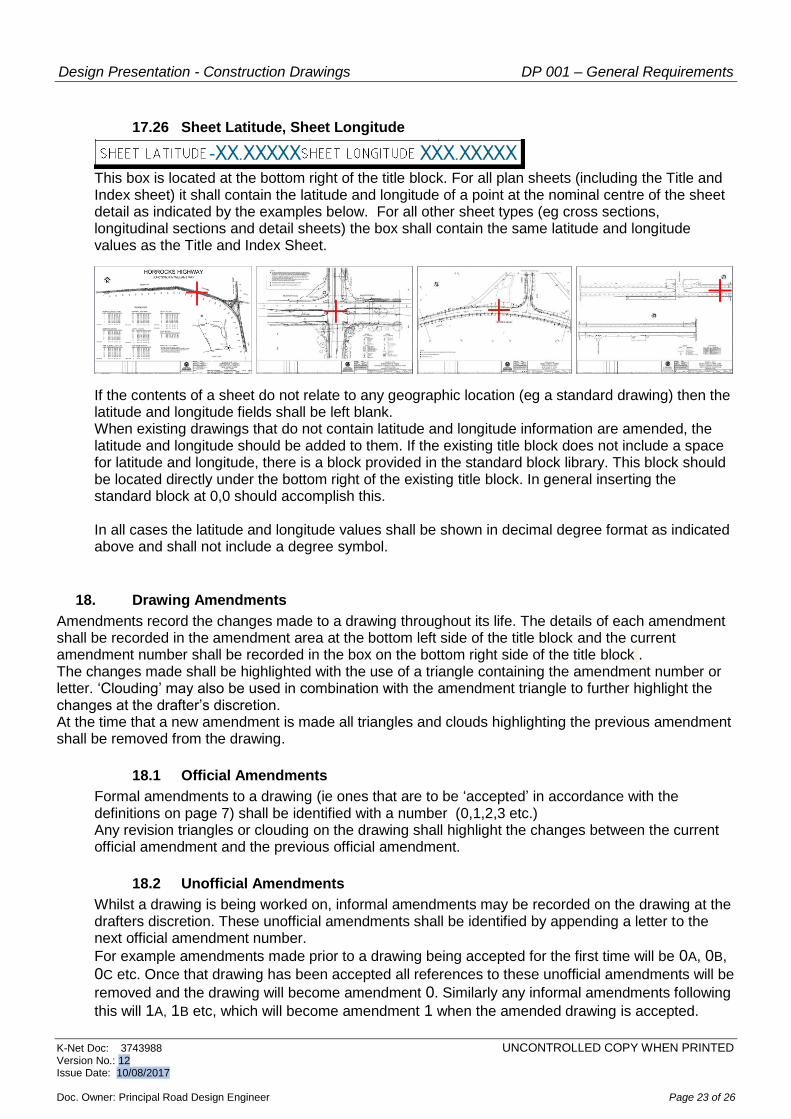
17.26 Sheet Latitude, Sheet Longitude
This box is located at the bottom right of the title block. For all plan sheets (including the Title and Index sheet) it shall contain the latitude and longitude of a point at the nominal centre of the sheet detail as indicated by the examples below. For all other sheet types (eg cross sections, longitudinal sections and detail sheets) the box shall contain the same latitude and longitude values as the Title and Index Sheet.
If the contents of a sheet do not relate to any geographic location (eg a standard drawing) then the latitude and longitude fields shall be left blank. When existing drawings that do not contain latitude and longitude information are amended, the latitude and longitude should be added to them. If the existing title block does not include a space for latitude and longitude, there is a block provided in the standard block library. This block should be located directly under the bottom right of the existing title block. In general inserting the standard block at 0,0 should accomplish this. In all cases the latitude and longitude values shall be shown in decimal degree format as indicated above and shall not include a degree symbol.
18. Drawing Amendments
Amendments record the changes made to a drawing throughout its life. The details of each amendment shall be recorded in the amendment area at the bottom left side of the title block and the current amendment number shall be recorded in the box on the bottom right side of the title block . The changes made shall be highlighted with the use of a triangle containing the amendment number or letter. ‘Clouding’ may also be used in combination with the amendment triangle to further highlight the changes at the drafter’s discretion. At the time that a new amendment is made all triangles and clouds highlighting the previous amendment shall be removed from the drawing.
18.1 Official Amendments
Formal amendments to a drawing (ie ones that are to be ‘accepted’ in accordance with the definitions on page 7) shall be identified with a number (0,1,2,3 etc.) Any revision triangles or clouding on the drawing shall highlight the changes between the current official amendment and the previous official amendment.
18.2 Unofficial Amendments
Whilst a drawing is being worked on, informal amendments may be recorded on the drawing at the drafters discretion. These unofficial amendments shall be identified by appending a letter to the next official amendment number.
For example amendments made prior to a drawing being accepted for the first time will be 0A, 0B,
0C etc. Once that drawing has been accepted all references to these unofficial amendments will be
removed and the drawing will become amendment 0. Similarly any informal amendments following
this will 1A, 1B etc, which will become amendment 1 when the amended drawing is accepted.

Design Presentation - Construction Drawings DP 001 – General Requirements
K-Net Doc: 3743988 UNCONTROLLED COPY WHEN PRINTED Version No.: 12 Issue Date: 10/08/2017 Doc. Owner: Principal Road Design Engineer Page 24 of 26
19. Superseding Drawings
At times a new drawing may ‘supersede’ or ‘partly supersede’ an older drawing. When this occurs both the new and old drawings must have one of the following cross reference notes added. On the SUPERSEDED drawing:
THIS SHEET IS SUPERSEDED BY DRG ???? SHT ???? or
THIS SHEET IS PART SUPERSEDED BY DRG ???? SHT ???? On the SUPERSEDING drawing:
THIS SHEET SUPERSEDES DRG ???? SHT ???? or
THIS SHEET PART SUPERSEDES DRG ???? SHT ???? Note: The cross reference note may list multiple drawing and sheet numbers if required. These cross reference notes represent an amendment to the drawing; as such the relevant processes for amending drawings as detailed in section 18 shall apply. When only part of a drawing is superseded, it shall be made clear on the drawing which area/detail is no longer current. Cross reference notes shall be drawn in paper space and located in the lower right corner of the drawing above the title area. They shall be on layer D-ENHA–General Notes. Text shall be Red, 5mm high.
20. Filenames
Drawing filenames shall consist of the drawing number and sheet number . Individual PDF files shall also include the amendment letter / number. The format shall be as follows:
20.1 DWG Files
1234 Sheet 0005.dwg Where: 1234 is the drawing number 0005 is the sheet number
20.2 Individual PDF Files
1234 Sheet 0005-AMD 6.pdf Where: 1234 is the drawing number 0005 is the sheet number 6 is the amendment number

Design Presentation - Construction Drawings DP 001 – General Requirements
K-Net Doc: 3743988 UNCONTROLLED COPY WHEN PRINTED Version No.: 12 Issue Date: 10/08/2017 Doc. Owner: Principal Road Design Engineer Page 25 of 26
21. Drawing Transmittal Requirements
All drawings shall be submitted to DPTI in both DWG and PDF format and shall be named in accordance with Section 20. Where the drawings are being sent by email the maximum size of any single email must not exceed 10MB. Paper copies may also be requested, in this case it shall be the original prints that are supplied rather than photocopies or scans of these prints. Prior to submission these files should be checked to ensure that they conform to the requirements of this document including the following.
21.1 DWG Files
Shall be in either AutoCAD 2013 format (preferred) or AutoCAD 2010 format.
Shall only contain one drawing sheet (multiple drawings on separate layout tabs will not be accepted)
Shall not contain any custom objects or proxy graphics.
Shall be purged to remove unused content
Shall have the current layer set to ‘0’
Shall have ‘Base’ set to 0,0,0
Shall not contain any paperspace objects outside the area of the titleblock.
Shall be saved with the drawing being zoomed to extents in paper space. During the course of the project, drawings and XRefs shall be supplied unbound, whereas at project completion all XRefs shall be bound to the host drawing. Where a drawing includes a scanned image in accordance with clause 10, the image file must accompany the main DWG file. No other files should be transmitted unless their use has been expressly authorised in writing by the DPTI Design Manager. This includes such things as Plot style tables, font files, line style files and shape files.
21.2 PDF Files
All PDF files shall be created at full size using the plot style “DPTI-RD-DesignBlack” During the course of the project, upon request these shall be combined into a single multipage PDF file, whereas at project completion they must be provided as individual files, (one PDF file for each drawing sheet). PDF files shall include layer information but not be restricted or password protected in any way.
21.3 Drawing Details Spreadsheet
Each set of drawing sheets submitted shall be accompanied by a single spreadsheet containing specific key details from the sheet title blocks. This spreadsheet shall be in .XLS or .XLSx format and shall contain one row for each drawing sheet and eleven columns containing the information indicated below:

Design Presentation - Construction Drawings DP 001 – General Requirements
K-Net Doc: 3743988 UNCONTROLLED COPY WHEN PRINTED Version No.: 12 Issue Date: 10/08/2017 Doc. Owner: Principal Road Design Engineer Page 26 of 26
Column A
Filename (filename of the relevant drawing sheet)
Column B
Drawing Number (item 1 below)
Column C
Sheet Number (item 2 below)
Column D
Road Number (item 3 below)
Column E • Road Name (item 4 below)
Column F • Drawing Title (items 5,6 & 7 appended together)
Column G
Comments (item 8 prefixed by the word “Amendment “)
Column H
RRDstart (item 9 below)
Column I
RRDend (item 10 below)
Column J
Latitude (Item 11 below)
Column K
Longitude (item 12 below)
Where the drawings being submitted are amendments to existing drawings, the spreadsheet need only contain any new information that is being added for the first time, for example sheet latitude and sheet longitude.
Appendix A – DPTI Layer Matrix
The DPTI Layer Matrix is now accessed from the DPTI CAD Support Files FTP site located at ftp.transportsa.com.au The file is located in the top level of the CAD Support Files folder and the filename is “CAD Matrix.xls” The matrix is updated on a regular basis. There is an “Issue Date” on Page 1 to help differentiate between versions and at every update the changes are highlighted.