design patterns lab
TRANSCRIPT

Department of Information Technology
Design Patterns Lab Lab Manual [Subject Code]
I M Tech – II Semester [Branch: IT]
1

Department of Information Technology
Lab Manual for the Academic Year 2008-09(In accordance with JNTU syllabus)
SUBJECT : DP LAB
SUBJECT CODE :
SEMESTER :
STREAM : Department of Information Technology
INSTRUCTOR :
PROGRAMMERS :
Head IT
2

Department of Information Technology
Lab Manual for the Academic Year 2008-09(In accordance with JNTU syllabus)
Suggestions from Principal:
Enhancement if any:
Comments:
3

INDEX
S. No Contents
1 Lab Objective
2 Introduction About Lab
3 Guidelines to Students
4
List of Lab Exercises
4.1 Syllabus Programs (JNTU)
4.2 Additional and Advanced Programs
5
1.Description about UML
2. Description about DP
6 Solutions for Programs
7 Solutions for Additional Programs
8 References
4

LAB OBJECTIVE
Overview Object ModelUML
Basic Model Advanced Models
Class & Object Collaboration Sequence
Use Cases Advanced Modeling
Component Diagram Deployment Diagrams
INTRODUCTION ABOUT LAB
There are 66 systems (Compaq Presario) installed in this Lab. Their configurations are as follows:
Processor : AMD Athelon ™ 1.67 GHz
RAM : 256 MB
Hard Disk : 40 GB
Mouse : Optical Mouse
Network Interface card : Present
Software
All systems are configured in DUAL BOOT mode i.e., Students can boot from Windows XP or Linux as per their lab requirement.
This is very useful for students because they are familiar with different Operating Systems so that they can execute their programs in different programming environments.
Each student has a separate login for database access
Oracle 9i client version is installed in all systems. On the server, account for each student has been created.
5

This is very useful because students can save their work ( scenarios’, pl/sql programs, data related projects ,etc) in their own accounts. Each student work is safe and secure from other students.
Latest Technologies like DOT NET and J2EE are installed in some systems. Before submitting their final project, they can start doing mini project from 2nd year onwards.
MASM ( Macro Assembler ) is installed in all the systems
Students can execute their assembly language programs using MASM. MASM is very useful students because when they execute their programs they can see contents of Processor Registers and how each instruction is being executed in the CPU.
Rational Rose Software is installed in some systems
Using this software, students can depict UML diagrams of their projects.
Softwares installed: C, C++, JDK1.5, MASM, OFFICE-XP, J2EE and DOT NET, Rational Rose.
Systems are provided for students in the 1:1 ratio.
Systems are assigned numbers and same system is allotted for students when they do the lab.
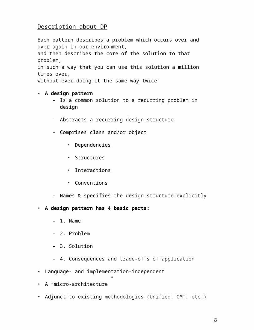
Description about DP
Each pattern describes a problem which occurs over and over again in our environment, and then describes the core of the solution to that problem, in such a way that you can use this solution a million times over, without ever doing it the same way twice“
• A design pattern– Is a common solution to a recurring problem in design
– Abstracts a recurring design structure
– Comprises class and/or object
• Dependencies
6

• Structures
• Interactions
• Conventions
– Names & specifies the design structure explicitly
• A design pattern has 4 basic parts:
– 1. Name
– 2. Problem
– 3. Solution
– 4. Consequences and trade-offs of application
• Language- and implementation-independent
• A “micro-architecture”
• Adjunct to existing methodologies (Unified, OMT, etc.)
• No mechanical application
– The solution needs to be translated into concrete terms in the application context by the developer
Goals
• Codify good design– Distil and disseminate experience
– Aid to novices and experts alike
– Abstract how to think about design
• Give design structures explicit names
– Common vocabulary
– Reduced complexity
– Greater expressiveness
• Capture and preserve design information
7
– Articulate design decisions succinctly
– Improve documentation
• Facilitate restructuring/refactoring
– Patterns are interrelated
– Additional flexibility
Description about UML
INTRODUCTION
The Unified Modeling Language (UML) is a graphical language for visualizing, specifying, constructing, and documenting the artifacts of a software-intensive system.The UML offers a standard way to write a system's blueprints, including conceptual things such as business processes and system functions as well as concrete things such as programming language statements, database schemas, and reusable software components."
The important point to note here is that UML is a 'language' for specifying and not a method or procedure. The UML is used to define a software system; to detail the artifacts in the system, to document and construct - it is the language that the blueprint is written in. The UML may be used in a variety of ways to support a software development methodology.
A modeling language for specifying, visualizing, constructing, and documenting Used to derive or evolve a system Means to capture and communicate a knowledge about a system Focuses on understanding a subject via creating a model It unifies the language of communication about a system Uses visualization Can be used as a 'blueprint' of a system Can be used through out the lifecycle of the system
UML is NOT
A visual programming language, but a visual modeling language A tool or repository specification, but a modeling language specification A process, but enables processes
UML is a general purpose, broadly applicable, tool-supported, (industry standardized) modeling language
Where does UML fit?
UML at its widest formalizes the notion of concepts and defines a language of specifying modes
8

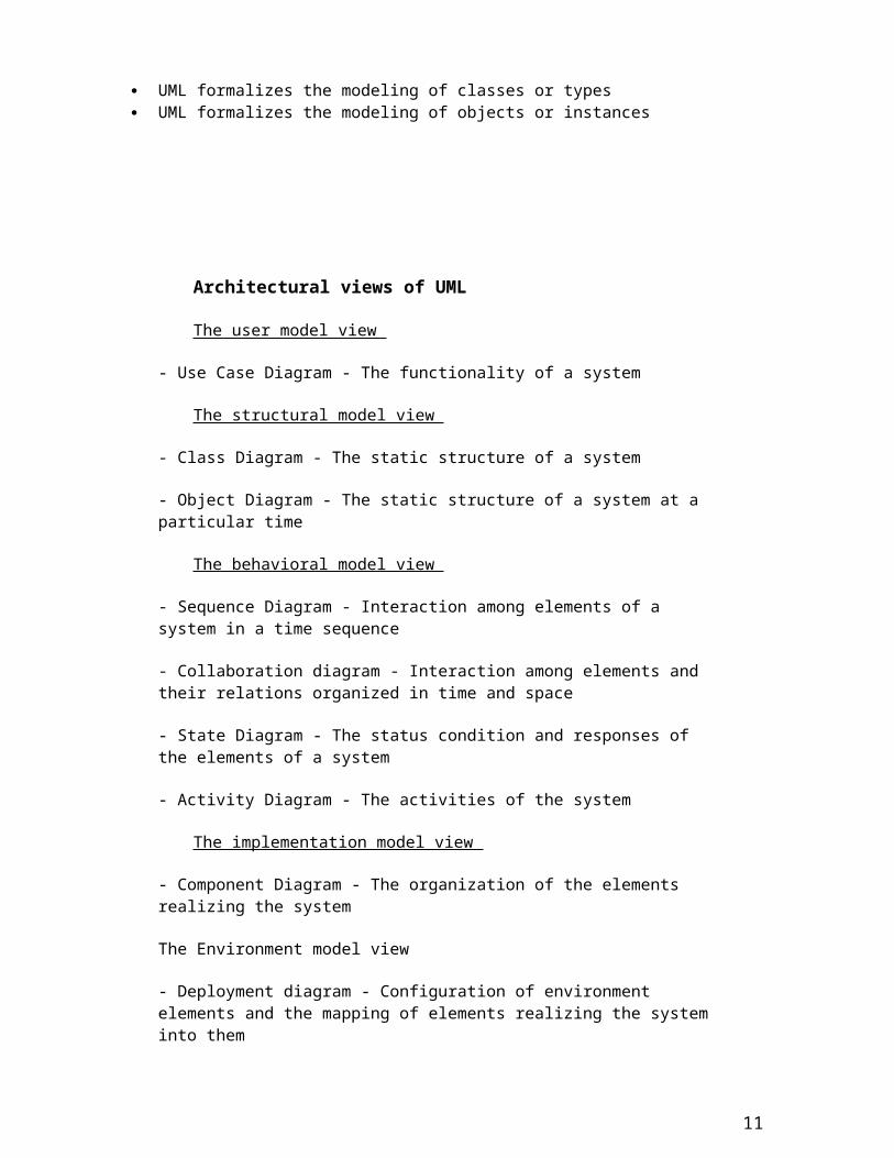
UML formalizes uses the above level to formalize the paradigm concepts (OO) UML formalizes the modeling of classes or types UML formalizes the modeling of objects or instances
Architectural views of UML
The user model view
- Use Case Diagram - The functionality of a system
The structural model view
- Class Diagram - The static structure of a system
- Object Diagram - The static structure of a system at a particular time
The behavioral model view
- Sequence Diagram - Interaction among elements of a system in a time sequence
- Collaboration diagram - Interaction among elements and their relations organized in time and space
- State Diagram - The status condition and responses of the elements of a system
- Activity Diagram - The activities of the system
The implementation model view
- Component Diagram - The organization of the elements realizing the system
The Environment model view
- Deployment diagram - Configuration of environment elements and the mapping of elements realizing the system into them
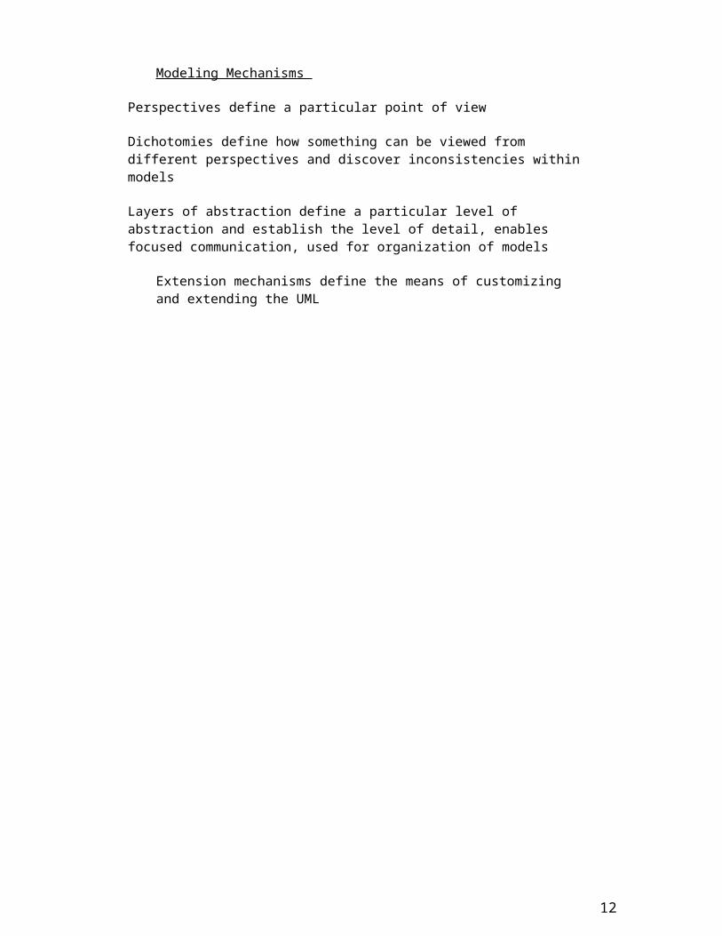
Modeling Mechanisms
Perspectives define a particular point of view
9

Dichotomies define how something can be viewed from different perspectives and discover inconsistencies within models
Layers of abstraction define a particular level of abstraction and establish the level of detail, enables focused communication, used for organization of models
Extension mechanisms define the means of customizing and extending the UML
10
Index PageS. No. Date Program / Experiment Page
No.Sign / Remarks
11
Annexure - 2
Index PageS. No. Date Program / Experiment Page
No.Sign / Remarks
12
Annexure - 2

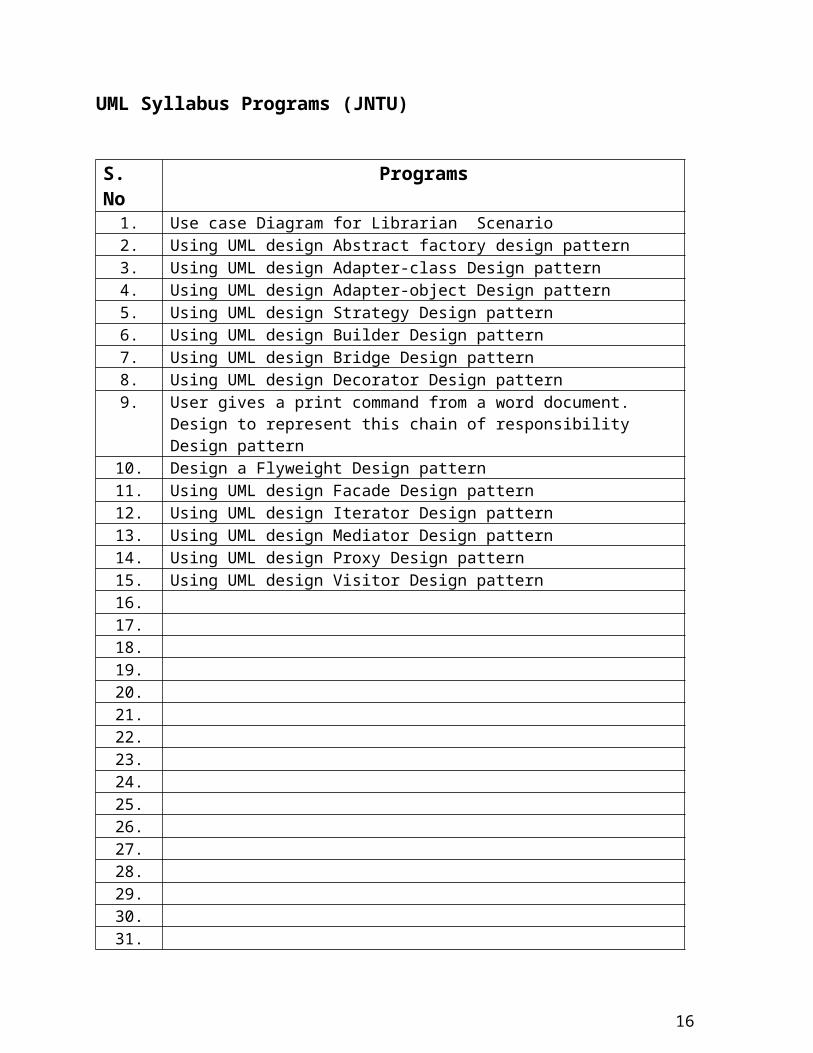
UML Syllabus Programs (JNTU)
S. No Programs1. Use case Diagram for Librarian Scenario2. Using UML design Abstract factory design pattern3. Using UML design Adapter-class Design pattern4. Using UML design Adapter-object Design pattern5. Using UML design Strategy Design pattern6. Using UML design Builder Design pattern7. Using UML design Bridge Design pattern8. Using UML design Decorator Design pattern9. User gives a print command from a word document. Design to represent this
chain of responsibility Design pattern10. Design a Flyweight Design pattern11. Using UML design Facade Design pattern12. Using UML design Iterator Design pattern13. Using UML design Mediator Design pattern14. Using UML design Proxy Design pattern15. Using UML design Visitor Design pattern16.17.18.19.20.21.22.23.24.25.26.27.28.29.30.31.33.34.35.36.37.38.
13

1. Use case Diagram for Librarian Scenario.
14

2. Using UML design Abstract factory design pattern.
15
3 .Using UML design Adapter-class Design pattern.
16

4. Using UML design Adapter-object Design pattern.
17

5. Using UML design Strategy Design pattern.
18

6. Using UML design Builder Design pattern.
19

7. Using UML design Bridge Design pattern.
20

8. Using UML design Decorator Design pattern.
21

9. Design to represent this chain of responsibility Design pattern.
22

10. Design a Flyweight Design pattern.
23

11. Using UML design Facade Design pattern.
24

12. Using UML design Iterator Design pattern.
25

13. Using UML design Mediator Design pattern.
26

14. Using UML design Proxy Design pattern.
27

15. Using UML design Visitor Design pattern.
28