design optimization of wind turbines optimization of wind turbines cp-max design environment first...
TRANSCRIPT
Tech
nisc
heU
nive
rsitä
tMün
chen
Win
dEn
ergy
Inst
itute
An Algorithmic Framework for the Multi-Disciplinary Design Optimization of
Wind TurbinesCarlo L. Bottasso (†,*), Pietro Bortolotti (†), Alessandro Croce (*)
(†) Technische Universität München, Germany(*) Politecnico di Milano, Italy
4th Wind Energy Systems Engineering Workshop DTU, Roskilde, Denmark,13-14 September 2017

Des
ign
Opt
imiz
atio
n of
Win
d Tu
rbin
esCp-Max Design Environment
First release: 2007, improved and expanded since thenApplications: academic research and industrial blade design
Cost:AEPAerodynamic parameters
Cost:Initial Capital Cost (ICC)Structural parameters(rotor and tower)
Cost:Physics-based CoEParameters:Aerodynamic and structural
Controls:model-based (self-adjusting to changing design)

Des
ign
Opt
imiz
atio
n of
Win
d Tu
rbin
esAlgorithmic Approach
Improving accuracy by multi-level analysis
Monolithic one-shot formulation of the constrained design problem
Issues with the monolithic approach:- Improving well-posedness
- Improving computational efficiency

2D FEM sectional model
Blade and tower beam models
Structural design parameters
Aeroservoelastic multibody model
Aerodynamic design parameters
Constraints:• Max tip deflection• Ultimate & fatigue loads• Natural frequencies• Buckling• Manufacturing constraints• Geometric constraints• Noise• …
Optimizer
min CoEsubject to constraints
Control synthesis
Load & performance analysis: • DLCs• AEP• Campbell• Noise• …
CoE model
Configurational designparameters
Sub-system models
Des
ign
Opt
imiz
atio
n of
Win
d Tu
rbin
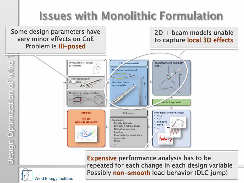
esIssues with Monolithic Formulation
Some design parameters have very minor effects on CoE
Problem is ill-posed
Expensive performance analysis has to be repeated for each change in each design variablePossibly non-smooth load behavior (DLC jump)
2D + beam models unable to capture local 3D effects

Des
ign
Opt
imiz
atio
n of
Win
d Tu
rbin
esIssues with Monolithic Formulation
2D + beam models unable to capture local 3D effects

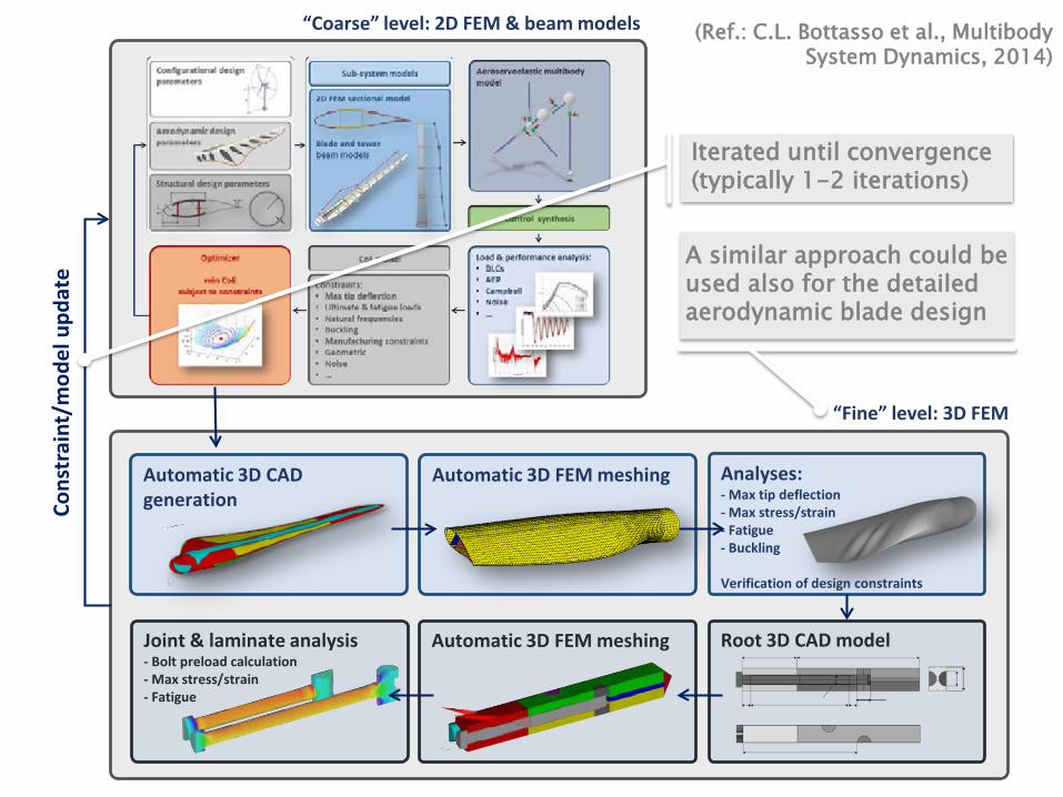
Automatic 3D CAD generation
“Fine” level: 3D FEM
“Coarse” level: 2D FEM & beam models
Analyses:- Max tip deflection- Max stress/strain- Fatigue- Buckling
Verification of design constraints
Cons
trai
nt/m
odel
upd
ate
Automatic 3D FEM meshing Root 3D CAD modelJoint & laminate analysis- Bolt preload calculation- Max stress/strain- Fatigue
Automatic 3D FEM meshing
(Ref.: C.L. Bottasso et al., Multibody System Dynamics, 2014)
Iterated until convergence (typically 1-2 iterations)
A similar approach could be used also for the detailedaerodynamic blade design

Des
ign
Opt
imiz
atio
n of
Win
d Tu
rbin
es Fine-level verification of:
1) Stress/strain/fatigue/frequency/max tip deflection:• Constraints violated at first iteration on 3D FEM model• Modify constraints based on 3D FEM analysis• Converged at 2nd iteration
2) Buckling:• Buckling constraint violated at first iteration• Update skin core thickness• Update trailing edge reinforcement strip • Converged at 2nd iteration
The Importance of Multi-Level Design
Peak stress on initial model
ITERATION 1ITERATION 0
Nor
mal
ized
str
ess
Fatigue damage constraint satisfied
ITERATION 1ITERATION 0
Fatig
ue d
amag
e in
dex
Increased trailing edge reinforcement
ITERATION 1ITERATION 0
Trai
ling
edge
str
ip th
ickn
ess
ITERATION 1ITERATION 0
Thic
knes
s
Increased skin core thickness

Des
ign
Opt
imiz
atio
n of
Win
d Tu
rbin
esBeyond a Monolithic Formulation
Some design parameters have very minor effects on CoE
Problem is ill-posed

Des
ign
Opt
imiz
atio
n of
Win
d Tu
rbin
esBeyond a Monolithic Formulation
Some design parameters have very minor effects on CoE
Problem is ill-posed
Solution: exploit weak couplings among optimization variables
Examples:Structural variables:
ICC (strong), AEP (weak)Aerodynamic variables, for given rotor radius & solidity and blade thickness & tapering:
AEP (strong), ICC (weak)
(Refs:P. Bortolotti et al., Wind Energy, 2017;P. Bortolotti et al., Wind Energ. Sci., 2016;C.L. Bottasso et al., Multibody Syst. Dyn., 2015)

Aerodynamic Optimization: max AEPOpt. variables: chord and twist distributions, airfoil positionsConstraints: max chord, max blade tip speed, σc, τc, σt, τt
Structural Optimization: min ICCOpt. variables: thickness of blade structural components, tower wall thickness and diameters, composite material parameters Constraints: stress, strain, fatigue damage for blade and tower, max tip displacement, natural frequencies
CoE model
Macro Optimization: min CoEOpt. variables: Rotor diameter, turbine height, cone, uptilt, blade shape parameters σc, τc, σt, τtConstraints: max loads, max turbine height
Control synthesis
Load calculation
3D FEM verification
Opt. variables CoE + constraints
Until converged
Unt
il co
nver
ged
Acoustic analysis
Pre-bend optimization
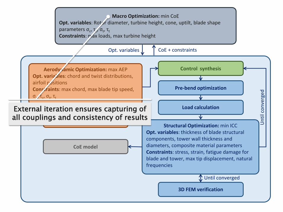
Exploit weak couplings among optimization variablesOriginal problem formulated as well-posed nested sub-optimizationsEach sub-optimization can be used independently (e.g., pure aerodynamic or structural optimizations)
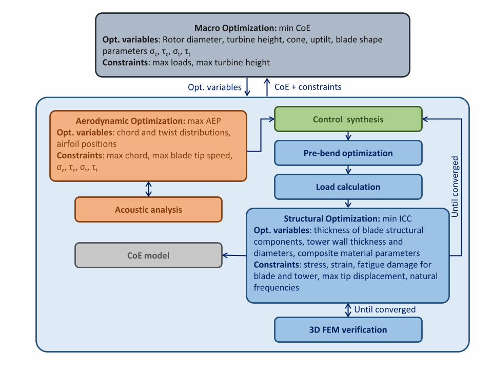
Aerodynamic Optimization: max AEPOpt. variables: chord and twist distributions, airfoil positionsConstraints: max chord, max blade tip speed, σc, τc, σt, τt
Structural Optimization: min ICCOpt. variables: thickness of blade structural components, tower wall thickness and diameters, composite material parameters Constraints: stress, strain, fatigue damage for blade and tower, max tip displacement, natural frequencies
CoE model
Macro Optimization: min CoEOpt. variables: Rotor diameter, turbine height, cone, uptilt, blade shape parameters σc, τc, σt, τtConstraints: max loads, max turbine height
Control synthesis
Load calculation
3D FEM verification
Opt. variables CoE + constraints
Until converged
Unt
il co
nver
ged
Acoustic analysis
Pre-bend optimization
External iteration ensures capturing of all couplings and consistency of results
Des
ign
Opt
imiz
atio
n of
Win
d Tu
rbin
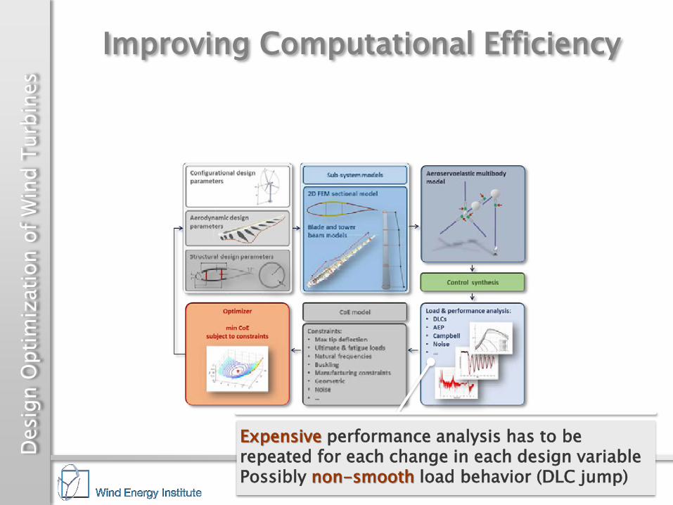
esImproving Computational Efficiency
Expensive performance analysis has to be repeated for each change in each design variablePossibly non-smooth load behavior (DLC jump)

Aerodynamic Optimization: max AEPOpt. variables: chord and twist distributions, airfoil positionsConstraints: max chord, max blade tip speed, σc, τc, σt, τt
Structural Optimization: min ICCOpt. variables: thickness of blade structural components, tower wall thickness and diameters, composite material parameters Constraints: stress, strain, fatigue damage for blade and tower, max tip displacement, natural frequencies
CoE model
Macro Optimization: min CoEOpt. variables: Rotor diameter, turbine height, cone, uptilt, blade shape parameters σc, τc, σt, τtConstraints: max loads, max turbine height
Control synthesis
Load calculation
3D FEM verification
Opt. variables CoE + constraints
Until converged
Unt
il co
nver
ged
Acoustic analysis
Pre-bend optimization
Temporary load freezing within structural optimizationTypically converges in 2-3 iterationsAs long as it converges, freezing will not affect solution accuracy
(Ref: C.L. Bottasso et al., Multibody Syst. Dyn., 2012, 2014, 2015)
Load update to ensure consistency

Des
ign
Opt
imiz
atio
n of
Win
d Tu
rbin
esAdditional Features:
Composite Optimization Idea: • Define a parametric composite material model (mechanical properties vs. cost)• Identify the best material for each component within the modelResult:• Wind turbine designer: pick closest existing material within market products• Material designer: design new material with optimal propertiesExample: INNWIND.EU 10 MW
▲Redesign of spar caps laminateOptimum is between H-GFRP and CFRP
H-GFRP Optimized F-CFRP
Spar Caps Laminate
-20
-10
0
10
60
Diff
eren
ce fr
om B
asel
ine
[%]
Blade Cost
Blade Mass
Redesign of the shell skin laminateOptimum is between Bx-GFRP and Tx-GFRP ▼
Bx-GFRP OptimizedShell Skin Laminate
-4
-2
0
2
4
6
Diff
eren
ce fr
om B
asel
ine
[%]
Blade Cost
Blade Mass
Combined optimum: Blade mass -9.3%, blade cost -2.9%
Des
ign
Opt
imiz
atio
n of
Win
d Tu
rbin
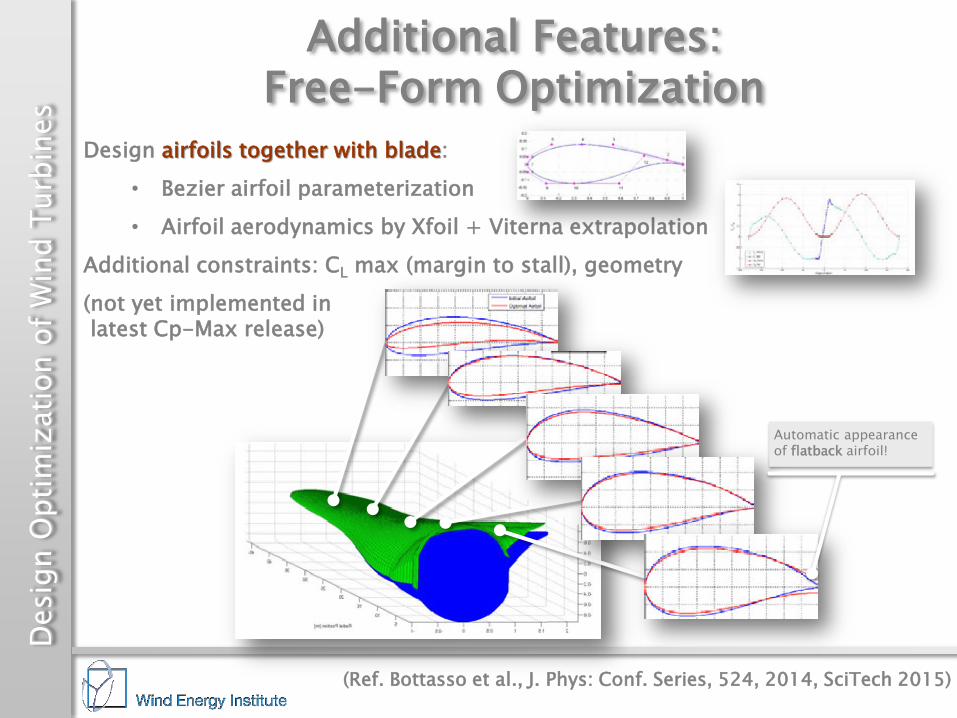
esAdditional Features:
Free-Form OptimizationDesign airfoils together with blade:
• Bezier airfoil parameterization• Airfoil aerodynamics by Xfoil + Viterna extrapolation
Additional constraints: CL max (margin to stall), geometry (not yet implemented in latest Cp-Max release)
Automatic appearance of flatback airfoil!
(Ref. Bottasso et al., J. Phys: Conf. Series, 524, 2014, SciTech 2015)

Des
ign
Opt
imiz
atio
n of
Win
d Tu
rbin
esApplications: Passive Load Alleviation
Full-span passive load mitigation: Loaded structure deforms in order to self-reduce loading
Potential advantages: no actuators, no moving parts, no sensors
Application: IEA Task 37 3.35MW wind turbine1. Each passive technology individually2. Integrated passive technologies: larger rotor at similar loading
Composite fiber rotation (F-BTC) Offsetting of spars (O-BTC)Aerodynamic sweeping (S-BTC)
(Details in Bortolotti et al., Wind Energy, 2017)

Des
ign
Opt
imiz
atio
n of
Win
d Tu
rbin
esApplications: Passive Load Alleviation
S-BTC & F-BTC: significant DEL and ultimate load benefits
O-BTC: limited benefits due to large spar caps and pronounced blade slenderness
(Details in Bortolotti et al., Wind Energy, 2017)

Des
ign
Opt
imiz
atio
n of
Win
d Tu
rbin
es Optimal combination of sweep and fiber rotation (F-S-BTC): larger rotor at similar loading
Constraints Results
New regulation in region II to limit AEP loss (variable fine pitch setting)
Applications: Passive Load Alleviation
(Details in Bortolotti et al., Wind Energy, 2017)

Des
ign
Opt
imiz
atio
n of
Win
d Tu
rbin
esSome References
P. Bortolotti, C.L. Bottasso, A. Croce, and L. Sartori: Integration of multiple passive load mitigation technologies by automated design optimization — The case study of a medium-size onshore wind turbine. Wind Energy, under review, 2017
P. Bortolotti, A. Croce, and C.L. Bottasso: Combined preliminary–detailed design of wind turbines. Wind Energ. Sci., 1, 1–18, doi:10.5194/wes-1-1-2016, 2016
C.L. Bottasso, P. Bortolotti, A. Croce, and F. Gualdoni: Integrated Aero-Structural Optimization of Wind Turbine Rotors. Multibody Syst. Dyn., doi: 10.1007/s11044-015-9488-1, 2015
C.L. Bottasso, F. Campagnolo, A. Croce, S. Dilli, F. Gualdoni, M.B. Nielsen: Structural Optimization of Wind Turbine Rotor Blades by Multi-Level Sectional/Multibody/3DFEM Analysis, Multibody System Dynamics, 32:87-116, 2014
C.L. Bottasso, F. Campagnolo, C. Tibaldi: Optimization-Based Study of Bend-Twist Coupled Rotor Blades for Passive and Integrated Passive/Active Load Alleviation, Wind Energy, 16:1149-1166, 2013
C.L. Bottasso, A. Croce, F. Campagnolo: Multi-Disciplinary Constrained Optimization of Wind Turbines, Multibody System Dynamics, 27:21-53, 2012
O.A. Bauchau, A. Epple, C.L. Bottasso: Scaling of Constraints and Augmented Lagrangian Formulations in Multibody Dynamics Simulations, ASME Journal of Computational and Nonlinear Dynamics, 4:021007, 2009
• P. Bortolotti, G. Adolphs, C.L. Bottasso: A methodology to guide the selection of composite materials in a windturbine rotor blade design process, J. Phys.: Conf. Ser. 753, 2016
• A. Croce, L. Sartori, M.S. Lunghini, L. Clozza, P. Bortolotti, C.L. Bottasso: Lightweight rotor design by optimalspar cap offset , J. Phys.: Conf. Ser. 753, 2016
• L. Sartori, P. Bortolotti, A. Croce, and C.L. Bottasso: Integration of prebend optimization in a holistic windturbine design tool, J. Phys.: Conf. Ser. 753, 2016

Des
ign
Opt
imiz
atio
n of
Win
d Tu
rbin
es • Strong couplings between aero and structural design variables
• Multi-level approach to marry high fidelity and computational effort
• Nested iterated sub-optimizations of original monolithic problem to improve well-posedness, efficiency and robustness
Open issues/outlook:• CoE: solutions are highly sensitive to cost model, need detailed
reliable models that truly account for all significant effects, problem partially alleviated by Pareto solutions (in progress)
• Include/improve physics-based sub-system models• Uncertainties everywhere (aero, structure, wind, …), move away from
deterministic design (but what about certification standards?), currently working on UQ and robust design
Conclusions
Input
Output
Simulationmodel