design, optimization and analysis of a single rotor
TRANSCRIPT

Design, Optimization and Analysis of aSingle Rotor Magnetic Gear ElectricMachine
Gunnar Charlie David Bjørk
Master of Energy and Environmental Engineering
Supervisor: Robert Nilssen, IEL
Department of Electric Power Engineering
Submission date: June 2017
Norwegian University of Science and Technology


Design, Optimization and Analysis of a SingleRotor Magnetic Gear Electric Machine
Charlie BjørkFaculty of Information Technology and Electrical Engineering,
Department of Electric Power Engineering,NTNU - Norwegian University of Science and Technology,
Trondheim - NO
Abstract—Magnetic gears have recently become serious con-tenders for mechanical gears in low speed applications thatrequire high torque. A magnetic gear features benefits such asinherent overload protection and low maintenance, while havingtorque handling capabilities similar to mechanical planetarygears. In this thesis an integrated magnetic gear brushlesspermanent magnet machine is designed, optimized and analyzedfor use in marine applications. This type of machine uses theprinciples of a magnetic gear within a synchronous machine,and preliminary investigations have shown that they exhibit verygood torque capabilities.
The machine is developed through a careful design process,which is validated by the finite element method in COMSOLmultiphysics. During the design process heavy calculations areperformed on a supercomputer, which enables the computationof very large parametric sweeps. Parallel to manually designing amachine, a particle swarm optimization of the same design, undersimilar limitations is performed on a supercomputer. The resultsfrom both design processes are compared and it is concludedthat the particle swarm method is a powerful tool that shouldbe used actively during design. However it is also found that theparticle swarm optimization should be controlled and iteratedby a machine designer, in order to make the design feasible inpractice.
The resulting machine designs achieve torque densities of98.8 kNm/m3 and 105.9 kNm/m3 respectively, which make themrelevant contenders to existing direct-drive solutions in termsof compactness. However low power factors of 0.187 and 0.188means that they require large and expensive converters whichis undesired in marine applications. Along with a quantitativeanalysis of losses in the machines the results are also reviewedqualitatively.
An alternative method of describing the principle of the mag-netic gear is adopted from the Vernier reluctance machine, andthe connection between these is clearly shown. This will hopefullymake the operating principle more intuitive to understand.
NOMENCLATUREPM Permanent magnetLSR Low speed rotorFEM Finite element methodMG Magnetic GearGE-MGEM General Electric MG Electric MachinePDD Pseudo Direct Drive
I. INTRODUCTION
Magnetic gears have recently received a fair bit of scientificattention due to promising performance. They avoid manyof the drawbacks of mechanical gears due to the input andoutput rotor not being mechanically connected. These include
Fig. 1. Radial cross section of a pure magnetic gear
Fig. 2. Radial cross section of the GE magnetic gear electric machine
inherent overload protection, reduced friction, reduced trans-mission of shaft vibrations, reduced mechanical maintenanceand reduced risk of contamination from lubrication oil. Theinherent overload protection is especially interesting for usein marine propulsion, e.g. if a propeller hits ice the overloadwill translate into slip in the gear instead of depreciating thegears.
This thesis is inspired by the high performing magnetic gearproposed in [1] and depicted in Fig. 1. This paper has inspiredmany recent papers, and a study comparing magnetic gears tomechanical planetary gears [2] showed that they can match oreven surpass the performance of their mechanical counterparts.An evolution of the magnetic gear has been to integrate it into
1

a synchronous permanent magnet (PM) machine and therebyremoving the gearbox altogether. A General Electric (GE)patent [3] proposed to substitute the high speed rotor of amagnetic gear with three phase armature windings, as depictedin Fig. 2. Other papers proposed to integrate a magnetic gearin its entirety into a synchronous machine, keeping both rotorswhile having both two [4] and three [5] air-gaps. The versionwith two rotors and two air-gaps was dubbed the ”pseudodirect drive” PDD and is depicted in Fig. 3.
A large PDD designed in [6] for marine propulsion achieveda torque density of >100 kNm/m3 and a PF of �0.9. Com-pared to regular state of the art PM machines, which may havetorque densities as high as 60 kNm/m3, this is an extraordinaryresult. Transverse flux machines have achieved torque densitiesof up to 80 kNm/m3 [6], but suffers from poor PFs whichincreases converter size and cost.
Due to the reported torque performance of the PDD it wasselected for a comparison with the GE topology [3] in a previ-ous comparative analysis performed by the author [7]. The GEtopology, hereby referred to as the General Electric magneticgear electric machine (GE-MGEM), performed considerablybetter than the PDD measured by its torque density. It alsofeatured benefits such as less PMs and a simpler mechanicalstructure. This resulted in a desire to design, optimize thedesign and analyze the machine more throughout. Thereforethe purpose of this thesis is to design such a machine intendedfor use in marine applications. Both an iterative classical de-sign process and a full particle swarm optimization algorithmis performed on the model. A supercomputer is utilized forheavy computations. The resulting design proposals from bothmethods are then analyzed and benchmarked. Simulations areperformed by the finite element method (FEM) in COMSOLmultiphysics 5.2a.
Practically this thesis starts with a literature review of themagnetic gear and corresponding magnetic gear machines, putinto a historical context. This is followed by a throughoutexplanation of the working principle, where this is explainedin two different ways, and the connection to Vernier machinesis examined. The FEM modeling specifics are described ina section, and the developed model is used for the designoptimization and analysis of the proposed designs. Manualoptimization is performed in a process that consist of making ahypothesis of how a parameter effects the torque performanceand then evaluating this with FEM simulations. In a way thesimulations act as an experiment made to validate or discarda hypothesis, in accordance with the hypothetico deductivescientific method [8].
II. BACKGROUND
The specific design chosen in this thesis is directly basedon the pure magnetic gear depicted in Fig. 1. This designhas been available for quite some time, but has not beengiven a large amount of attention until recently. A shorthistorical overview is therefore given before the reasoningbehind choosing this specific topology is revealed. Additional
magnetic gear machine topologies relevant to this paper arebriefly reviewed.
A. Magnetic Gears
As explained in [7] the magnetic gear in its current form,depicted in Fig. 1, was described in a 1964 US patent [9].However this design did not receive notable attention inscientific papers, perhaps due to poor performance of PMsat the time. Different papers [10] and [11] described magneticgears in the 1980s, but they suffered from poor performanceeither from poor magnetic material or from restraints relatedto the magnetic circuit design.
Development of high coercivity rare earth PMs in the 1980s[12] made it possible to improve the performance of magneticgears. In a design proposed in 2001 [1] the magnetic circuitdesign of [9] was combined with the high performing PMsand it achieved very promising performance. The radial crosssection of this design is depicted in Fig. 1 and it forms thebasis for the machine analyzed in this thesis. Several studies ofthis gear, among them [13] and [14], showed that the magneticgear is a viable option for mechanical gears. A comparativestudy between mechanical planetary gears and the magneticgear was conducted in [15]. It concluded that the torquedensity of a magnetic gear can match, or even surpass thatof its mechanical counterpart. It was shown that safety factorsgreatly affect the sizing of mechanical gears. Magnetic gearshowever, have benefits compared to mechanical gears when itcomes to fault situations and do not need such large safetyfactors.
B. Magnetically Geared Electric Machines
In 2006 General Electric filed a patent application describ-ing a magnetic gear where the inner high speed rotor hadbeen replaced by a second stator with armature windings, asdepicted in Fig. 2. These windings produced a rotating fieldsimilar to that from the magnetic gear high speed rotor. A 2008paper [16] described this particular design scientifically and itwas further analyzed in [17]. In these papers it is concludedthat the design possesses distinct advantages for direct-driveapplications that require high torque at low speed. In this thesisreferences to this topology will be made by the abbreviationGE-MGEM.
In another topology introduced in [4] both rotors froma magnetic gear are integrated into an electric machine, asdepicted in Fig. 3. This topology has two rotors, one HSR andone LSR similar to a pure magnetic gear, but with additionalarmature windings on the stator. In this thesis, referencesto this topology will be made by the abbreviation PDD forsimplicity.
C. Additional Magnetic Gear Machine Topologies
Additional to the two topologies mentioned so far, there areother topologies that utilize the ”magnetic gearing” effect. Thecommon denominator for machines following this effect is thatthey have similar air-gap space harmonics, that follow fromthe same equations. These equations are described in section
2
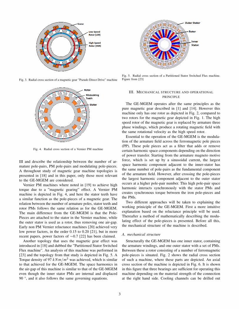
Fig. 3. Radial cross section of a magnetic gear ”Pseudo Direct Drive” machine
Fig. 4. Radial cross section of a Vernier PM machine
III and describe the relationship between the number of ar-mature pole-pairs, PM pole-pairs and modulating pole-pieces.A throughout study of magnetic gear machine topologies ispresented in [18] and in this paper, only those most relevantto the GE-MGEM are considered.
Vernier PM machines where noted in [19] to achieve hightorque due to a ”magnetic gearing” effect. A Vernier PMmachine is depicted in Fig. 4, and here the stator teeth havea similar function as the pole-pieces of a magnetic gear. Therelation between the number of armature poles, stator teeth androtor PMs follows the same relation as for the GE-MGEM.The main difference from the GE-MGEM is that the Pole-Pieces are attached to the stator in the Vernier machine, whilethe outer stator is used as a rotor, thus removing one air-gap.Early non PM Vernier reluctance machines [20] achieved verylow power factors, in the order 0.15 to 0.20 [21], but in morerecent papers, power factors of �0.7 [22] has been claimed.
Another topology that uses the magnetic gear effect wasintroduced in [18] and dubbed the ”Partitioned Stator SwitchedFlux machine”. An analysis of this machine was performed in[23] and the topology from that study is depicted in Fig. 5. ATorque density of 97 kNm=m2 was achieved, which is similarto that achieved for the GE-MGEM. The space harmonics inthe air-gap of this machine is similar to that of the GE-MGEMeven though the inner stator PMs are internal and displaced90 °, and it also follows the same governing equations.
Fig. 5. Radial cross section of a Partitioned Stator Switched Flux machine.Figure from [23]
III. MECHANICAL STRUCTURE AND OPERATIONALPRINCIPLE
The GE-MGEM operates after the same principles as thepure magnetic gear described in [1] and [14]. However thismachine only has one rotor as depicted in Fig. 2, compared totwo rotors for the magnetic gear depicted in Fig. 1. The highspeed rotor of the magnetic gear is replaced by armature threephase windings, which produce a rotating magnetic field withthe same rotational velocity as the high speed rotor.
Essential to the operation of the GE-MGEM is the modula-tion of the armature field across the ferromagnetic pole pieces(PP). These pole pieces act as a filter that adds or removecertain harmonic space components depending on the directionof power transfer. Starting from the armature magneto motiveforce, which is set up by a sinusoidal current, the largestspace harmonic component adjacent to the inner-stator hasthe same number of pole-pairs as the fundamental componentof the armature field. However, after crossing the pole-piecesthe largest harmonic component adjacent to the outer statoroccurs at a higher pole-pair number. This high pole-pair spaceharmonic interacts synchronously with the stator PMs andcreates synchronous torque between the iron pole-pieces andthe PMs.
Two different approaches will be taken to explaining theworking priniciple of the GE-MGEM. First a more intuitiveexplanation based on the reluctance principle will be used.Thereafter a method of mathematically describing the modu-lating effect of the pole-pieces is presented. Before all this,the mechanical structure of the machine is described.
A. mechanical structure
Structurally the GE-MGEM has one inner stator, containingthe armature windings, and one outer stator with a set of PMs.Between these a rotor consisting of a number of ferromagneticpole-pieces is situated. Fig. 2 shows the radial cross sectionof such a machine, where these parts are depicted. An axialcross section of the machine is depicted in Fig. 6. It is shownin this figure that three bearings are sufficient for operating thismachine depending on the material strength of the connectionat the right hand side. Cooling channels can be drilled out
3

Fig. 6. Axial cross section of the GE-MGEM
Fig. 7. 3D drawing of the rotor
in the plate to provide air-flow through the air-gaps of themachine.
Structural integrity of the rotor is achieved by using nonmagnetic material with relative permeability � 1 between thepole-pieces. A three dimensional drawing of such a rotor isprovided in Fig. 7. Due to the strength requirements, it may benecessary to use non-laminated ferromagnetic material, whichwill contribute to increased losses.
B. Principle explained after the reluctance principle
As mentioned in section II the GE-MGEM has similari-ties with the Vernier PM machine, and this similarity waspointed out in [24]. The Vernier PM machine is a furtherevolution of the Vernier Reluctance machine [25], which ismore thoroughly described in [20] and [21]. An explanationof the working principle of the GE-MGEM will be presented,inspired by the explanation given for the vernier reluctancemachine.
Fig. 8 shows a small linearized section of the GE-MGEM.Stator slot-pitch and rotor pole-pitch are denoted ps and prrespectively. The figure shows the rotor before and after it hasbeen rotated a distance (ps � pr ).
Essential to this explanation is the axis of maximum per-meance, which is the path of least reluctance in the magneticcircuit. The red and blue PMs has alternating remanent fluxdensity in the radial direction. Thus the easiest way for a fluxline to cross the air-gaps from the inner stator is through thepole-piece aligned with it and through the PM pointing in thesame direction. This corresponds to the left dashed line in Fig.8a. After rotating the rotor a distance (ps�pr ) to the right thepreffered flux path follows the rightmost dashed line referringto Fig. 8b.
(a) Rotor position 1
(b) Rotor position 2
Fig. 8. A sequence of the rotor rotating an angle (ps � pr ), where ps andpr represent the stator slot-pitch and rotor pole-pitch respectively
In this way the rotation of the axis of least reluctance andthe magneto motice force (mmf) rotate synchronously, whilethe rotor rotates at a fraction of the mmf speed. The rotor pole-pieces wish to constantly align with the axis of least reluctancewhile the mmf keeps rotating, and this creates torque in themachine. This phenomenon is also known as reluctance torque.
The ratio of the rotational speed of the axis of leastpermeance to the rotational axis of the rotor becomes the gearratio
GR Dps
ps � pr; (1)
where ps is the stator slot-pitch and pr is the rotor pole-pitch, i.e. the circumferential distance between the center oftwo adjacent pole-pieces. The pitch is given by the number ofPM pole-pairs, Po, on the outer stator and the number of rotorpole-pieces, Ns , along a full circumference of the machine, Y.Substituting ps D Y=Po and pr D Y=Ns into (1) gives
GR DNs
Ns � Po: (2)
In a machine consisting of a number of PM pole-pairs andferromagnetic pole-pieces there will be a certain periodicityto the axis of least reluctance. Starting from a pole-piece thatis in alignment with a PM with the correct remanence, i.e.the leftmost line in Fig. 8a, the displacement of the rotorpole-pieces from alignement with corresponding PMs for thefollowing pole-pieces becomes
.ps � pr /; 2 � .ps � pr /; :::; n � .ps � pr /: (3)
4

Alignment reoccurs when the displacement is equal to onerotor pole-piece-pitch, i.e. when n � .ps � pr / D ps . Solvingfor n and substituting for ps and pr similarly to before yields
n Dps
ps � prD
Ns
Ns � Po: (4)
This represents the number of rotor pole-pieces between eachrepeating axis of least reluctance. It is also the number of pole-pieces that has to be covered by the mmf wave from a fullelectrical period of the armature current. Thus the pole-pairnumber of the armature windings, Pi , can be calculated as
Pi DNs
Ns=.Ns � Po/D Ns � Po: (5)
Substituting this into (2) gives the gear ratio of the machine
GR DNs
Pi: (6)
It is actually slightly incorrect to call the path which theflux would follow for the path of least reluctance becausethe reluctance of PMs is equal, independent of the directionof their remanence. In the above explanation the PMs withopposite remanence than the field crossing the air-gaps havesimply been ignored. This is plausible in practice because thePM with remanent flux density in the same direction as thearmature flux will be the ”easiest” path for the flux to follow.
C. Principle explained with modulating equation
Another quantitative explanation of the working principleis presented in [14]. This explanation defines a modulatingfunction that describes the modulating effect the ferromagneticpole-pieces have on both the magnetic field from the armatureand the PMs. The field experienced at a distant r from eitherfield source is a product of two sinuses, where the first termrepresents the field without pole-pieces and the second termrepresents the modulating function of the pole-pieces. For theradial component this is
Br .r;�/ D
.X
mD1;3;5;:::
brm.r/cos.mp.� ��r t /Cmp�0//
� .�r0 CX
jD1;2;3;:::
�rj .r/cos.jns.� ��st ///:
(7)
Similarly the circumferential component is
B� .r;�/ D
.X
mD1;3;5;:::
b�m.r/sin.mp.� ��r t /Cmp�0//�
.��0 CX
jD1;2;3;:::
��j .r/cos.jns.� ��st ///:
(8)
Here p is the number of corresponding pole-pairs and ns is thenumber of pole-pieces. �r and �s are the rotational velocitiesof the relevant magnetic field and the pole-pieces respectively.The Fourier coefficients of the flux density distribution inradial and circumferential direction are brm and b�m and the
modulating Fourier coefficients of the flux densities are �rjand ��j .
Rewriting (7) and (8) can be done to produce (9) [14].This equation gives the number of space harmonic pole-pairsadjacent to one of the field sources due to the modulation ofthe field from the other source, i.e. the field from either theinner stator armature current or from the outer stator PMs. Forthe GE-MGEM this would for example be the resulting spaceharmonics adjacent to the outer PMs due to the modulation ofthe armature field.
pm;k D jmp C knj:
m D 0; 1; 2; :::;1
k D 0;˙1;˙2; :::;˙1
(9)
Here pm;k is the number of resulting space harmonic pole-pairs associated with the m and k harmonic, p is the numberof pole-pairs and n is the number of pole pieces. The largestharmonics occur for m=1 and k=-1 and thus the equationguarding the number of PM pole-pairs and the number of pole-pieces is given by
Po D jPi �Nsj; (10)
where Po is the number of outer PM pairs, Pi is the numberHSR PM pairs and Ns is the number of pole-pieces. Duringdesign it is important to match the number of outer PM pairswith the number of space-harmonic pole-pairs resulting fromthe modulation of the armature field. By adding the assumptionthat Ns is always larger than Pi and rearranging (10) it leadsto
Pi D Ns � Po; (11)
which is similar to what was found in (5). Rotational speed ofthe space harmonic field can be deduced in a similar manneras shown in equation (12).
�m;k DmPi
mPi C kNs�r C
kNs
mPi C kNs�s : (12)
Here �r and �s are the rotational velocities of the PM fieldand the pole-pieces respectively. Setting m=1 and k=-1, whileletting �s D 0 gives a gear ratio of
Gr DNs � Pi
Pi; (13)
Where Ns is the number of pole pieces, Pi is the numberof inner pole pairs and Po is the number of PM pole pairs,which in this case is on the output rotor. Magnetic flux crossingan air-gap between two ferromagnetic iron pieces creates apulling force acting on both components in opposite direction[26]. This means that there is an equal force pulling on the PMstator and on the ferromagnetic pole-pieces, but in oppositedirections, implying that both the PMs and the ferromagneticpole pieces can be used as the output rotor given that the otheris held stationary. However, as pointed out in [14] this resultsin different gear ratios depending on which is chosen as the
5

Fig. 9. Flux density adjacent to the inner stator as a function of angularposition, along with corresponding harmonic spectrum
Fig. 10. Flux density adjacent to the outer stator as a function of angularposition, along with corresponding harmonic spectrum
output rotor. With stationary PMs and rotating pole-pieces, thegear ratio is as given in (14)
Gr Dns
pi: (14)
In this thesis the pole-pieces will be chosen as the rotor asthis gives a higher gear-ratio, and hopefully a better torquedensity.
It is clear that the equation for Gear-ratio (14) and therelation between pole numbers (11) are equal to the equationsdeveloped in section III-B, namely (6) and (5).
D. FEM verification of working principle
A stationary simulation was run for the GE-MGEM geom-etry in COMSOL multiphysics to generate the flux densitydistribution in both air-gaps. A fast fourier transform (fft) wasperformed on this distribution, for a topology with Pi D 8,Ns D 45 and Pi D 37.
Fig. 9 shows the flux density distribution adjacent to theinner stator. It is expected that the fundamental 8 pole-pair
component from the armature field is the largest harmoniccomponent, and this is confirmed by the harmonic spectrumshown in the bottom of the figure. Interestingly a largecomponent is present with a pole-pair number of 40. Thiscomponent was unexpected, and it is not believed to contributeto torque creation. Instead it may cause problems such aslosses and vibrations.
The flux density distribution adjacent to the PMs on theouter stator is depicted in Fig. 10, along with its harmonicspectrum. This clearly shows the effect of the modulatingpieces with the largest space harmonic component appearingat 37 pole-pairs, as expected from (10). Coinciding withthis is a reduction of the fundamental component of thearmature field, such that the high pole-pair harmonic becomesthe dominating flux component in the machine. It is thiscomponent that causes the torque production of the machineby interacting synchronously with the PM pole-pairs. Theseplots also indicate that most of the torque production is takingplace in the outer air-gap.
IV. FEM MODELLING
COMSOL Multiphysics 5.2 is used for all the simulationsin this thesis. For analyzing big data sets Matlab R2014b isused. A description of the specific FEM modeling will follow,which will make it easier to reproduce the simulations forverification.
COMSOL Multiphysics is a general purpose physics simu-lator based on advanced numerical methods. It makes it possi-ble to solve advanced nonlinear unbalanced partial differentialequations that are impossible to solve analytically and whichwould be largely inconvenient to solve numerically by hand.E.g. Navier-Stokes equation in fluid dynamics or Amperes lawin electromagnetics.
Comsol is structured in a tree form with global definitionsaffecting the Component nodes. The study node controls howthe components should be analyzed. Finally the results nodeenables post prosessing of the simulated data, such as plottingand data export.
The model in this thesis is a 2 dimensional radial cross sec-tion of the GE-MGEM as depicted in Fig. 2 and described insection III. In Comsol this geometry is quite straightforward toproduce. Every variable is parameterized in global definitionsand the geometry adapts automatically to changes in these.Every domain has to be assigned a material.
Due to the nature of pole-number selection, guarded by(10), symmetry is only available for a select few combinations.The model therefore includes the entire circumference of themachine. Due to this the model becomes quite large and taxingon computational power, especially when performing timesimulations. Therefore the design optimizations are performedwith stationary simulations before the resulting designs areanalyzed in the time domain.
A. Materials used
The materials used are found in COMSOLs built in library,with the exception of the permanent magnets which are
6

defined manually. Permanent magnets are defined with relativepermeability �r D 1:05, conductivity � D 0:667 � 106 andrelative permittivity �r D 1, based on material properties ofNdFeB. The steel used is non grain oriented, Silicon Steel50PN270.Normal copper is used as the winding material,while regular air is used for the air-gap.
Laminated steel can be used for the back-iron (yoke) ofboth stators, but the rotor pole-pieces may have to be non-laminated for the sake of material strength. Maximum fluxdensity is limited by the effects of saturation, and the B-Hcurve that determines this is depicted in appendix B-B.
B. Torque calculation
Torque is normally calculated in one of two different ways,which yield approximately the same results. The built in forcecalculation uses Maxwell stress tensors to calculate torquearound the boundary of the iron pole-pieces.
Using Maxwell stress tensors, torque is calculated as asurface integral surrounding the rotor like a cylinder in theair-gap. For a two dimensional model, this translates to a lineintegral in the air-gap. Under ideal circumstances the torqueshould be the constant, independent of the line integral radius,as long as the line is in the air-gap. However as pointed outby Arkkio [27] this is not the case in practice and variationsof torque for the integration at different radiuses in the air-gapcan be noticeable. The Maxwell stress tensor line integral canbe expressed as
Te D1
�0
Z 2�
0
r2BrB�d�; (15)
where Te is torque, Br is the radial flux density and B� iscircumferential flux density. r is the radius for which thefunction is being evaluated and �0 is the universal constantfor permeability in vacuum.
Arkkio pointed out another method developed in [28] thatreplaces the line integral with a volume integral over a hollowshell surrounding the rotor. In a two dimensional case thisbecomes a surface integral of a disk situated in the air-gap.The torque equation thus becomes
Te DL
�0.rs � rr /
ZSag
rBrB�dS; (16)
where Te is torque, L is machine length, rs is outer shellradius, rr is inner shell radius Br is radial flux density andB� is circumferential flux density. r is the radius for whichthe function is being evaluated. This method has been provenby Arkkio, and others, to give more reliable results and tobe less prone to numerical noise than the maxwell stresstensors. However in the case of the GE-MGEM model thismethod required additional two domains in each air-gap, whichincreased the mesh creating time. This proved to be criticalfor the time consumption during the design optimizationsimulations, which required the model to rebuild the meshmultiple times for different model parameters. Therefore thebuilt in method based on eq. (15) is used in this paper.
Fig. 11. Optimal start angle air-gap flux
C. Optimal Pole Piece start angle
The simulation is carried out at synchronous speed atsynchronous frequency. For synchronous machines inducedtorque can be expressed as
�ind D kBRBnetı; (17)
where k is a constant, BR is the rotor flux density and Bnetis the vector sum of the rotor and stator flux density [29].ı is known as the torque angle and it is the same angleas the phase shift between the terminal voltage V� and theinternal generated voltage EA. This equation is not exact whenaccounting for magnetic saturation, however it is valid forqualitatively understanding machine operation.
From the equation it is clear that a certain rotor position willcreate the highest output torque and this position is essentialto know for the parametric optimization of the machine. If thisangle is wrong different designs will compete under differentassumptions and it will be impossible to compare the results.Because of the nature of the GE-MGEM working principle itis quite complicated to describe this angle with the generalmachine concepts. Instead a qualitative explanation based onFEM simulations will be performed.
Simulations revealed that the optimal rotor start angle wasachieved when a rotor pole-piece was aligned with the tooth ofhighest flux density, while this axis passed right in between anouter stator PM pole-pair. Referring to Fig. 11 the inner statorarmature current is at its maximum in the A phase coil, whichmakes the resultant mmf vector point in a horizontal direction.Making a rotor tooth align with this flux vector assures that amaximum amount of flux is crossing the air-gap. However thisdoes not in itself create torque, and it has to be combined withthe correct position of the PMs on the outer stator. A sweepthat rotated the PMs a full pole-pitch revealed that the highesttorque was achieved when the axis of alignment passed rightthrough the middle of an outer stator PM pole-pair. In Fig. 11this axis is depicted as a black arrow. Fig 24 in appendix Ashows the results of rotating the PM magnets while keepingthe rest stationary.
7

Fig. 12. Cross section of an outboard POD
TABLE IAPPLICATION REQUIREMENTS
Parameter Requirement UnitGear ratio 5-8Torque 200 kNmSpeed output 200 rpmPower 4.2 MWMax diameter 1.2 m
V. APPLICATION AND REQUIREMENTS
A. Applications
The GE-MGEM is designed for marine applications thatrequire high torque at relatively low speed. A relevant appli-cation in this regard is for use in outboard PODs. A POD isdepicted in Fig. 12 and consists of an electric motor driving apropeller for marine propulsion. PODs are also called azimuththrusters if they in addition to provide propulsion providesteering by rotating the pods in horizontal direction. Outboardpods provide benefits compared to traditional propeller shaftsby reducing shaft vibrations felt in the hull and freeing spaceaboard the vessel. Azimuth pods can also assist dynamicanchoring and docking by providing thrust in different direc-tions. However, because the pods are submerged in water, thediameter of the pods is crucial for hydrodynamic reasons. Itis therefore desireable with a machine that has a high torquedensity in order to minimize effect of underwater drag. A lowpower factor is also undesirable, because it increases the VA-rating and thus the volume occupied by the converter insidethe ships hull.
B. Requirements
Based on the discussion in the last paragraph a list ofrequirements for the machine is given in table I. Values inthis table represent boundaries for the design optimization.
VI. DESIGN OPTIMIZATION
A throughout design optimization process has been carriedout for the GE-MGEM. First an optimal combination of pole-pair and pole-piece numbers was found before each parameterwas evaluated through simulations. In addition to a manualdesign optimization a Particle Swarm Optimization (PSO)algorithm was performed for the model, and this is presentedin section VII. The results from this was compared to the
TABLE IIOPTIMIZATION VARIABLES AND CONSTRAINTS FOR THESE
Parameter initial value x 2Inner pole-pairs Pi 6 [2, 30]Outer pole-pairs Po 29 Ns �Pi
Rotor pole-pieces Ns 35 [12, 150]Yoke thickness inner stator 0.03 [0.01, 0.1]Slot thickness 0.07 [0.01, 0.1]Slot ratio 0.5 [0.1, 0.9]Inner air-gap length 0.005 [0.003, 0.020]Rotor pole-piece thickness 0.025 [0.01, 0.1]Pole-piece ratio 0.5 [0.1, 0.9]Outer air-gap length 0.005 [0.003, 0.020]PM thickness 0.01 [0.005, 0.025]Stat PM ratio 0.97 [0.3, 1]Yoke thickness outer stator 0.03 [0.01, 0.1]
Fig. 13. Torque vs pole-pieces and pole-pairs
results from the manual design process before they whereanalyzed in the time domain.
The optimization objective is to find a set of parameters thatmaximize machine torque, based on the developed model. Anobjective function for the GE-MGEM can be written as
maximizex
�orque.x/;
where x are the parameters that are going to be optimized,constrained by the limits in table II. This objective function isused for both the manually performed design considerationsand the Particle Swarm Optimization.
A. Pole-number selection
The number of pole-pairs on the stator and the number ofpole-pieces on the rotor follows the relation in (10). Thereforeone of the parameters is always given by two of the other.
In order to find a pole-number combination to base thedesign optimization on, a large parametric sweep was per-formed by utilizing the NTNU supercomputer Vilje [30]. Theparameters that are changed are number of rotor pole-piecesNs and armature pole-pairs Pi , which in turn determine thenumber of outer stator PM pole-pairs. A simulation was runthat covers every combination of these parameters that satisfythe required gear-ratio requirements given in table I, andfollowing the relation in (6). A Matlab script generating thelist is given in appendix C.
Fig. 13 shows the results from this sweep. From the figureit is obvious that there is a clear maxima of this function. The
8

maximum torque is 111.82 kNm and occurs for Pi D 8 andNs D 45 which gives a gear-ratio of 5.63.
Cogging torque in a PM machine is caused by the tendencyof the rotor to prefer the position where the net force betweenthe PMs and the iron is at its lowest. This is greatly affectedby the number of pole-pairs and it is desirable to have a designwhere the forces acting on the iron pole-pieces by the PMsare balanced out. Cogging torque appears as ripple on theoutput torque of the machine, and is unfortunate for severalreasons. The effect causes uneven torque output which againleads to vibrations that are undesired in most applications.High frequency vibrations also cause mechanical noise.
A cogging torque factor (CTF) was adapted from [31] to themagnetic gear in [14] and it can be adopted directly by theGE-MGEM. The CTF is not exact, but it gives an indicationof how much cogging torque there will be for different pole-pair combinations. Adapted to the GE-MGEM the CTF canbe written
fct D2PiNs
Nlcm; (18)
where Pi is the number of armature pole-pairs and Ns isthe number of rotor Pole-Pieces. Nlcm is the least commonmultiple between the two. Inserting the parameters for max-imum torque results in CTF D 2 which is the lowest CTFobtainable with Pi D 8, and the gear ratio within the requiredlimits GR D 5:63. The effect of cogging is seen as the torqueripples in the time domain simulation in section IX.
Electrical frequency of the armature depends on the gearratio and pole-number selection. It was shown in [7] that itfollows the relation
fe DPiGRnout
60DNsnout
60; (19)
where nout is the constant rotational velocity of the rotorin rounds per minute (rpm). According to this relation themachine requires an electrical frequency of 150 Hz to drive therotor at the required 200 rpm with the selected pole numbers.
B. Stator yokes thickness
While determining the pole-piece numbers, a simulation wasrun for a similar sweep, but without the effect of magneticsaturation in the iron. This achieved considerably better perfor-mance than the saturated counterpart which indicates that someparts of the machine is heavily saturated. The non saturatedsweep is depicted in appendix A. Therefore a hypothesis thatmachine performance will increase by increasing the thicknessof the back iron is tested in FEM.
Fig. 14 shows the results from increasing the thicknessof the yoke of both stators simultaneously. It shows thatthe torque increases until the back-iron saturation no longerbottlenecks the machine. However it also shows that increasingthe thickness above 3.5 cm actually decreases the torqueperformance of the machine. Studying the flux lines for thecase with thicker yokes reveals that less flux crosses the air-gap. It is instead looping around in the inner stator. The reasonfor this could be that the saturation of the armature stator
Fig. 14. Torque vs Yoke thickness of both stators
Fig. 15. Torque vs Slot-Ratio
yoke forces some of the flux to take longer paths throughthe iron, that naturally has a higher reluctance. This increasesthe required mmf for the flux to cross the air-gap and thisflux therefore does not contribute to torque creation. As themachine has the same current input, this may instead increasethe reactance of the machine, thus giving it a poorer power-factor. A yoke thickness of 3.5 cm is therefore chosen for bothstators.
C. Slot-ratio
Slot-ratio is the ratio between tooth width and slot-pitchon the armature stator. A Slot-ratio of 0.5 indicates that theteeth are of the same width as the slots. Higher slot-ratiosmean that the slots are wider than the teeth and vice versa.From the simulations of stator yoke thickness a hypothesis isformed claiming that tooth saturation is bottlenecking machineperformance and that the performance will increase for a Slot-ratio lower than the initial 0.5. This is the case even thoughit means a reduction of the mmf, F D NI [26].
The results from this sweep is depicted in Fig. 15. Itindicates that a slot-ratio of 0.6 gives the highest torque,which contradict the initial hypothesis by not increasing for alower Slot-Ratio. It seems like the teeth where not completelysaturated and could endure a higher flux density. However ahigher slot-ratio than 0.6 led to a decrease in torque due tosaturation constraints. Studying the flux density of the machinefor the different slot-ratios reveals that a slot-ratio of 0.6 has aflux density in the tooth that corresponds to heavy saturationaccording to the H-B curve of the material. A compromiseslot-ratio of 0.55 is therefore chosen for this design.
9

Fig. 16. Torque vs Pole-Piece Ratio
Fig. 17. Torque vs Pole-Piece thickness
D. Pole-Piece ratio
Pole-Piece ratio is the ratio of ferromagnetic pole-pieces tothe pole-piece pitch on the rotor. E.g. a Pole-Piece ratio of 0.5means that there is as much iron as there is low permeabilitymaterial along the circumference of the rotor.
From the results depicted in Fig. 16 a pole-piece ratio of0.5 gives the highest output torque and is therefore chosen.
E. Pole-Piece thickness
As mentioned in section III the rotor consists of a number offerromagnetic pole-pieces, encapsulated in a low permeabilitymaterial. It is nesessary for this mix to be able to withstandthe high axial torque from the eletric machine along with anyforces from the mechanical load. The thickness of the pole-pieces is therefore critical for the mechanical strength of themachine, and a more throughout mechanical analysis should beperformed in order to determine weather the chosen thicknessis feasible. In this thesis however, only electromagnetic partof the design is considered and these calculations are not per-formed. From an electromagnetic point of view a hypothesis isthat thicker pole-pieces will result in a lower torque becauseit will be harder for the flux to cross from the inner to theouter stator.
Fig. 17 confirms the hypothesis that thinner pole-piecesresults in higher torque. However for pole-pieces thinner than2 cm this effect is reversed. A reason for this could be thatthe magnetic gearing effect depends on the modulation of themagnetic field over the pole-pieces, and if they become to thinthis effect is dampened. Studying the calculated flux densityadjacent to the outer PMs confirms this suspicion. Referringto Fig. 18 it is clear that the fundamental component fromthe armature field is larger for the thin pole-pieces than itis with thicker pole-pieces, thus confirming the effect on the
(a) Pole-piece thickness 1 cm
(b) Pole-piece thickness 10 cm
Fig. 18. Space flux density in the air-gap adjacent to the outer stator withvarying pole-piece thickness
Fig. 19. Torque vs air-gap length
modulation. However, for the thick pole-pieces, output torqueis lower according to Fig. 17 because less flux makes it acrossthe air-gaps.
Based on the above discussion a pole-piece thickness of 2,5cm is chosen. It is only slightly less than the maximum at 2cm, and it will provide more mechanical strength.
F. Air-gap length
Air-gap length is the most critical parameter for air-gap fluxdensity because of the high reluctance relative to iron [26].It is therefore expected that output torque will increase forsmaller air-gaps and decrease for larger. The air-gap lengthis therefore limited by mechanical considerations because itwould be ideal to have almost no air-gap. In this thesis initialair-gap length is 5 mm, with the lower limit being defined at3 mm. It is perhaps possible to have even smaller air-gaps,but it is comforting to have a certain knowledge of that thetopology is realistically achievable. The machine is a doubleair-gap machine and the simulations are run with both air-gapshaving the same length.
Torque vs air-gap length is depicted in Fig. 19. As expectedthe torque decreases as the air-gap length increases. An air-gap length of 5 mm is selected for analysis even though thebest solution is 3 mm. The reason behind this is to analyze
10

the machine on a realistic foundation and 5 mm is reasonablysimple to manufacture. However the result in Fig. 19 indicatesthat it is possible to achieve better performance by reducingthe air-gap to 3 mm, and a more throughout mechanicalanalysis should be performed for this design. For power factorimprovement, it may be necessary to decrease the load, inwhich case a smaller air-gap could be considered in order tostill achieve a high torque density.
G. Final Proposed Parameters
Accumulated from all these considerations and simulations,are the selected variables for a final proposed design. Theseparameters are rendered in table III along with the results fromthe PSO algorithm. The design will be further analyzed insection IX.
VII. PARTICLE SWARM OPTIMIZATION
As mentioned in the introduction a particle swarm optimiza-tion (PSO) algorithm was performed during the design of thismachine as an alternative to an iterative design process. Thealgorithm is given upper and lower boundaries of each param-eter and can freely choose solutions within these boundaries.Iterative approaches may return good results, but it can alsomiss out on some good solutions because of how differentparameters affect each other dynamically. For example duringthe pole number selection in section VI-A, the yoke thicknesswas held at a constant initial value. This may have overlookedsome better solutions that required a slightly thicker yoke dueto saturation. The PSO however can change each parameterfreely and might pick up this better solution. Accounting forthis codependency is perhaps the greatest advantage of a psoover the iterative method.
The PSO optimization was done in collaboration with afellow thesis student [32] who works with enabling tech-nologies. Previous work on optimization of a magnetic gear[33] was limited by computational power, and therefore asupercomputer was used for the calculations.
This section will contain a short qualitative description ofthe PSO principle followed by a description of a PSO proposeddesign.
A. PSO Principle
PSO algorithms have become popular in electrical machinedesign [34] since being proposed in [35].
It originates from a desire to understand the mechanisms orunderlying rules behind the fluid and synchronous movementsof a flock of birds or similarly for other animals social behaviorlike fish schools or herds. The synchrony of flocking behavioris thought of as animals efforts to maintain optimum distancebetween themselves and their neighbors.
Following the natural example the PSO algorithm starts byinitializing each agent in a population within a solution space,assigning each of them a position and a directional velocity.The agents constantly evaluate how good their current positionis and the directional change is determined by a combinationof their evaluation and the collective evaluation of the swarm.
TABLE IIIFINAL PROPOSED DESIGN FROM BOTH MANUAL DESIGN AND FROM THE
PSO ALGORITHM
Parameter Manual design PSO designInner pole-pairs Pi 8 4Outer pole-pairs Po 37 27Rotor pole-pieces Ns 45 31Yoke thickness inner stator 0.035 0.06Slot thickness 0.07 0.0802Slot ratio 0.5 0.5138Inner air-gap length 0.005 0.0044Pole-piece thickness 0.025 0.0419Pole-piece ratio 0.5 0.4171Outer air-gap length 0.005 0.0055PM thickness 0.01 0.0236Stat PM ratio 0.97 0.6510Yoke thickness outer stator 0.035 0.0588Gear-ratio 5.63 7.75
For each iteration of the algorithm the agents are moved to anew position where a new evaluation is calculated. Dependingon how good this evaluation is, and if there exist betterresults from the collective population, the position is eitherremembered or not, and the agents keep moving. This processis repeated until the algorithm terminates.
Walls are assigned to the solution space in such a way thatagents will only consider solutions from inside. These wallsrepresent limitations set upon the solution by mechanical andpractical considerations.
B. PSO Design Proposal
Table III depicts the proposed design from the PSO. ThePSO evaluated 11 variables which requires quite a lot ofcomputational power. A supercomputer was used for thecalculations, but difficulties surrounding the manual controlof multithreading for a COMSOL model delayed the processquite a bit and prevented multiple iterations of the full PSO.The parametric limits could perhaps have been better defined.
The results show a machine with a much higher gear-ratioand fewer poles than the manual design. It did achieve a highertorque performance, but by looking at the proposed variablesit is clear that an even higher torque could have been achieved.The reason for this is that the air-gap length proposed is higherthan the lower limit of 3 mm, for both air-gaps. A thinner air-gap will return a higher torque, and therefore better solutionsdo exist. However, the PSO is a great tool for pointing outinteresting solutions, when considering a new machine design,which in turn can be evaluated by the machine designer. As thedesign process evolves the limits of the PSO can be narroweddown following mechanical and power-system requirementsand considerations, while still providing useful input to thefinal design.
VIII. LOSSES
The losses in AC machines are generally divided into fourcategories. These are copper losses, core losses, mechanicallosses and stray losses [29]. Mechanical losses such as shaftfriction and windage are not considered in this thesis. Neitherare stray losses, which represents all losses that do not fit into
11

the other categories, such as end effects and flux leakage. Theother effects are described in this section, and analyzed furtherin section IX.
A. Copper Losses
Copper losses are caused by the resistance of the currentcarrying copper wires in the armature windings. They dependon wire resistance and current in the machine following therelation Ploss D 3RaI 2a .
In this thesis the copper losses are calculated analyticallyafter a method presented in [26]. DC resistance of a coil canbe calculated as
R DLcoil
�cuAcoil; (20)
where Lcoil is winding length in the direction of current flow,including end windings. �cu is copper conductivity and Acoilis the area of the coil cross section. Adopting an approachfrom [36] the AC resistance is calculated as 1.2 times theDC resistance. Because the machine is current excited this isenough information to calculate the losses in each coil. Thetotal number of coils is then .Pi � 3/.
B. Core losses
Core losses are the combination of hysteresis losses, eddy-current losses and anomalous losses. Hysteresis loss is theenergy required to align the domains of the ferromagneticmaterial in the direction of the magnetic field of the machine.Eddy current losses are resistive losses caused by circulatingcurrents induced in the iron due to a time varying magneticfield. Anomalous losses are described in [37] as causedby intricate phenomena such as microstructural interactions,magnetic directional dependency and nonhomogenous locallyinduced eddy currents.
Calculation of core losses have traditionally been based onthe assumption of sinusoidal flux density of varying magnitudeand frequency [38], according to the Steinmetz equation [39].However for higher flux densities than 1.0 T and for nonlinear magnetic materials this way of calculating losses isinaccurate. According to [38] a plurality of models have beenproposed that try to correct and modify the initial models, butthese models do not account for anomalous losses or considerflux harmonics. [38] also points out that measured valuesare systematically higher than the classical estimated values,which have been countered by adding corrective parameters inmagnitudes surpassing two. The classical ”evolved” method ofestimating losses under sinusoidal conditions is referred to as
P D Ph C Pe C Pa (21)
D khfB˛C kef
2B2 C kaf1:5B1:5; (22)
where Ph is hysteresis losses, Pe is eddy current losses andPa denotes anomalous losses. For the classical model Kh, Keand Ka are constant material coefficients for hysteresis-, eddy-current- and anomalous losses, while f is the frequency of themagnetic field and B is the flux density. However it has beenshown that the coefficients Kh, Ke and Ka are less constant
in practice than the classical model. [37] and [38] are amongpapers devoted to showing this non-linearity.
The underestimation of losses in the classical model isblamed by [38] on the waveform distortion, the complexityof machine structures and complex behavior of dynamichysteresis loops. To improve this it is proposed to evaluatethe magnetic fields at any point in the structure and develop adynamic model that accounts for varying frequencies and fluxdensities.
In the case of the GE-MGEM studied in this thesis, theoperation depends on the existence of flux harmonics and it istherefore believed that the traditional methods are inaccuratefor calculating core losses. A method based on evaluating thefield in each element of the mesh is therefore adopted. Themethod finds the frequency and flux density of each domainbefore calculating the core losses. This method is used for theyoke of both the stator and the rotor.
Losses in the PMs and in the iron pole-pieces of the rotorare estimated Comsol by making each PM and each pole-pair a single turn coil. From this approximate losses can becalculated.
Steel manufacturers do normally not provide the loss co-efficients directly. Instead they provide data for losses perkilogram for a frequency of 50 or 60 Hz [40], [41], whichis the nominal frequency of most power systems. It is be-yond the scope of this thesis to gather the require materialinformation necessary for estimating the material coefficientsby mathematical regression. Instead the calculated yoke losseswill be based on constants from [42].
C. Calculation of core losses in the GE-MGEM
Losses in the yoke of the machine is calculated with amatlab script that extracts the maximum flux density in eachdomain of the iron, and uses (22) on it. The values of theconstants Kh, Ke and Ka are constant for simplicity.
IX. ANALYSIS
A. Torque in the time domain
Both topologies were simulated in the time domain. Thesimulation struggled to converge when including magneticsaturation in the iron, however running the simulations withoutaccounting for saturation results in a somewhat higher torque.In this analysis the time-simulations are performed withoutsaturation, but the results are scaled with a factor that rep-resents the relative difference between the calculated torquefor the stationary solution of both models, with and withoutaccounting for saturation. This can be expressed as
K�;c D�max;saturated jtD0
�max;unsaturated jtD0; (23)
where � is torque and the subscript represents the condition.Torque values are per meter of the machine. The torquecorrection factor is not exact as it assumes a linear relationshipbetween the results limited by saturation and those that arenot. When accounting for magnetic saturation the history ofthe magnetic field affects the magnetization, in accordance
12

Fig. 20. Torque vs time for both designs
with the hysteresis loop [29]. In the time domain this meansthat the magnetization does not follow the external magneticfield instantaneously and these delays may cause variations inoutput torque. Because of these mechanisms the factor is onlyused to make the torque magnitudes more realistic. The effectson torque related to hysteresis is therefore not shown in thisthesis.
The manually designed case has a scaling factor of1:1588e5=1:2704e5 D 0:91 while the PSO design has a factorof 1:2589e5=1:4375e5 D 0:88. Applying these factors to thetime-plots of torque results in the graph of Fig. 20, wheretorque is shown for one electrical period for both designs.
The different x-axis lengths of the two plots is because ofthe difference in synchronous frequency for the two designs.A dip in the torque can be observed at the beginning ofeach simulation, before the curve levels out. This is causedby the eddy currents in the ferromagnetic pole-pieces andthe PMs. These currents are induced because the pole-pieceswant to contradict the changing field, by setting up its ownfield according to Lenz/Faradays law. Initially these currentsare zero, because the time derivate of the field is zero. Oncethe time-dependent solver has some data however, the eddy-currents start to appear.
Torque ripples are caused by a combination of coggingtorque and flux-variations due to eddy currents. This rippleamounts to � 4% and � 5% of average torque for the manualand PSO design respectively.
Required axial length of the machines is calculated basedon average output torque and the required output torque of200 kNm. This results in axial lengths of 1.79 m and 1.67 mfor the manual and the PSO design respectively.
B. Voltages and power-factors
The coil node of COMSOL 5.2a calculates the currentand voltage waveforms in the machine windings. These aredepicted for both the topologies in Fig. 21. With the machinesbeing current excited, the angle of the current is known. Apower factor can therefore be found by studying the phaseshift of the current and voltage in the same phase. This shift
(a) Manual design
(b) PSO design
Fig. 21. Coil voltage waveforms for each design along with the currentwaveform of phase A
is denoted �t in the figure. From this the power factor (PF)can be calculated as
� D2�f�t
PF Dcos�;(24)
where � is the phase shift and f is electrical frequency. ThePF for the manual and the PSO design at maximum obtainableload is 0.187 and 0.188 respectively. While obtaining the PF itis common to compensate for total harmonic distortion (THD).However, this is not done in this thesis based on a qualitativeconsideration of the voltage waveform. These PF values arevery poor compared to the claimed PF of � 0:9 in [6], whileachieving a torque density of 110 kNm=m3 for the largePDD mentioned in the introduction. Similarly [4] claimedthat the PF can surpass 0.9. These numbers are for the PDDtopology, but due to similar principles of operation, a certaincorrelation with the results from the GE-MGEM was expected.Low PFs are unfortunate because converter VA-ratings an PFsare inversely proportional, thus adding both cost and volumeto the final solution.
However, there are some key differences in the modelingbasis in these papers compared to this thesis along with manyunknowns. Firstly the large machine in [6] has a diameter of3.5 m which is 2.3 m larger than the designs in this thesis. Thisis believed to affect the torque density due to the scaling of theeffective air-gap area following the approximate relation � DkD2l [43], which may outweigh the increase in volume V D.D=2/2�l . D denotes outer diameter and l machine length.Secondly the air-gap lengths used in these papers are unknownand they may very well be lower than the 5 mm gaps used inthis thesis. As shown in section VI-F the torque output depends
13

Fig. 22. Induced eddy currents in the pole-pieces and PMs
heavily on air-gap length, and by using a thinner air-gap thetorque angle can be reduced while maintaining a high torquedensity, which may improve the power factor.
A more throughout analysis of the possibility to increasethe power-factor should be conducted before scrapping thedesigns. Interestingly it seems that the machines suffer fromthe same challenges as the Vernier reluctance machines withlow power factors. The low power-factor of hybrid verniermachines was shown by [44] to be an inherent feature ofvariable reluctance machines, and the GE-MGEM has beenshown to share many features of the vernier PM machine asmentioned in III. Advanced methods of improving Vernier PMmachine PF was proposed in [45], and could also be adoptedby the GE-MGEM.
C. Losses
The losses in the machines are expected to be dominatedby eddy current losses in the PMs and the pole-pieces. This isbecause these parts consist of non-laminated material whichallows currents to flow freely in axial direction. Fig. 22 showsa surface plot of the induced eddy currents in the pole-piecesand the PMs.
1) PM and pole-piece losses: An internal COMSOL func-tion calculates the power dissipation density in the pole-piecesand PMs. This is also called Joule Heating and is expressedas Q D JE, where J represents the current density vector andE represents the electric field vector. The results for the pole-pieces and PMs respectively are 440 and 535 kW/m for themanual design and 700 and 385 kW/m for the PSO design.These losses are very high, and measures should be taken toreduce them. Such measures could be sectioning the PMs orlaminating the steel pole-pieces. Regarding the pole-pieces,they were assumed not to be laminated due to rotor strengthrequirements, and this causes very large eddy currents.
2) Yoke core losses: Yoke losses are hard to predict formachines with a large number of large flux harmonics. Forthe calculation of these losses a script that follows the methoddescribed in section VIII is used. The sript is developed by[46] and identifies the flux density and frequency of each meshdomain. It then uses (22) to evaluate the losses. For this casethe constants used are for non grain oriented laminated steel50pn270 at 150 Hz. The constants used are Ke D 3:8724 �
10�5, Kh D 0:01838 and Ka D 0:0004 aquired from [42].
The resulting yoke core losses are 46 and 42 kW/m for themanual and PSO design respectively. As expected these lossesare lower than in the non laminated pole-pieces.
3) Resistive losses: Copper losses are calculated with theanalytical formula for DC resistance in (20) multiplied with afactor of 1.2 to estimate AC resistance. Current follows fromthe number of turns and the external current density of themodel. The length of each coil can be expressed as
Lcoil D 2Laxial C 2Lend ; (25)
where Laxial is total axial lenth of the machine and Lend isthe length of the end windings. The axial length of the machineis given in IX-A. End winding length depends on windingprinciple. For the models in this thesis this is defined as thecircumferential length of one pole-pitch angle for a radius tothe centre of the slots. By choosing the circumferential lengthinstead of the shortest distance, the additional length requiredto interleave the end windings is accounted for.
Inserting the dimensions from the model in (25) and (20)results in a resistance of 3:25 � 10�5 and 1:53 � 10�5 for themanual and pso design windings and correspondingly copperlosses are 145 W and 121 W.
X. CONCLUSION
A design process for a magnetic gear electric machinetopology has been performed by the use of FEM simulations.The design process was meticulously performed in an iterativeapproach assisted by simulations. In addition to this a fullparticle swarm optimization algorithm was completed, subjectto the same parameter constraints. It was shown to be apowerful tool for assisting a design process, and it proposeda design with better performance than the manual methodachieved.
Both the proposed designs where analyzed by FEM sim-ulations. The topologies achieved very high torque per ma-chine volume, as high as 98.8 kNm/m3 and 105.9 kNm/m3
respectively, which is beneficial when space is limited. Timedomain simulations however, resulted in power factors of0:187 and 0:188 for the two designs respectively, which isvery poor. This requires very large converters, which is a veryclear disadvantage in marine applications. Losses were alsocalculated, and the PM and pole-piece core losses where foundto dominate.
Throughout this thesis the relation between the magneticgear machines and the Vernier PM machines has been inves-tigated, and it can be concluded that they are very similar.Poor power-factors are an inherent problem in Vernier PMmachines and it seems like the analyzed machines are subjectto the same challenges.
Initial thoughts are therefore that the torque density advan-tage these designs have over state of the art PM machinesis outweighed by the much poorer power factors, and it isperhaps time to consider different topologies.
Further work could include investigation of how to improvethe power factor, without loosing the extraordinary torque
14

density. It may also include renaming the topology to a Vernierpartitioned stator machine.
ACKNOWLEDGMENT
The author would like to thank Prof. Robert Nilssen forfirst class supervising, as well as Dr.Eng. Alexey Matveev,Eirik Mathias Husum and the other employees at Rolls Roycemarine AS for excellent guidance.
A gratitude is also extended to fellow student Sol MajaFossen for performing the PSO on a supercomputer. Fellowoffice members Stian Bjornes and Usman Hassan deserve anacknowledgment for their input, and a special thanks is di-rected to Lasse Kløvstad for helping out with loss calculations.
REFERENCES
[1] K. Atallah and D. Howe, “A novel high-performance magnetic gear,”IEEE Transactions on magnetics, vol. 37, no. 4, pp. 2844–2846, 2001.
[2] E. Gouda, S. Mezani, L. Baghli, and A. Rezzoug, “Comparative studybetween mechanical and magnetic planetary gears,” IEEE Transactionson Magnetics, vol. 47, no. 2, pp. 439–450, 2011.
[3] W. Michal-Wolfgang, J. Hemmelmann, R. Qu, and P. L. Jansen, “Elec-tric machine apparatus with integrated, high torque density magneticgearing,” US Patent US8 358 044, 2006.
[4] K. Atallah, J. Rens, S. Mezani, and D. Howe, “A novel “pseudo”direct-drive brushless permanent magnet machine,” IEEE Transactionson Magnetics, vol. 44, no. 11, pp. 4349–4352, 2008.
[5] K. Chau, D. Zhang, J. Jiang, C. Liu, and Y. Zhang, “Design ofa magnetic-geared outer-rotor permanent-magnet brushless motor forelectric vehicles,” IEEE Transactions on Magnetics, vol. 43, no. 6, pp.2504–2506, 2007.
[6] D. Powell, S. Calverley, F. De Wildt, and K. Daffey, “Design and anal-ysis of a pseudo direct-drive propulsion motor,” in Power Electronics,Machines and Drives (PEMD 2010), 5th IET International Conferenceon. IET, 2010, pp. 1–2.
[7] C. Bjørk, “A comparison of integrated magnetic gear electric machinesfor marine propulsion,” Specialisation project, NTNU, 2016.
[8] K. Elgmork, Vitenskapelig metode. Universitetsforlaget, 1985.[9] M. J. T. B., “Magnetic transmission,” US Patent US3 378 710, 1964.
[10] D. Hesmondhalgh and D. Tipping, “A multielement magnetic gear,” inIEE Proceedings B-Electric Power Applications, vol. 127, no. 3. IET,1980, pp. 129–138.
[11] K. Tsurumoto and S. Kikuchi, “A new magnetic gear using permanentmagnet,” IEEE Transactions on Magnetics, vol. 23, no. 5, pp. 3622–3624, 1987.
[12] K. J. Strnat, “Modern permanent magnets for applications in electro-technology,” Proceedings of the IEEE, vol. 78, pp. 923 – 946, 1990.
[13] P. O. Rasmussen, T. O. Andersen, F. T. Jorgensen, and O. Nielsen,“Development of a high-performance magnetic gear,” IEEE Transactionson Industry Applications, vol. 41, no. 3, pp. 764–770, 2005.
[14] K. Atallah, S. Calverley, and D. Howe, “Design, analysis and realisationof a high-performance magnetic gear,” IEE Proceedings-Electric PowerApplications, vol. 151, no. 2, pp. 135–143, 2004.
[15] E. Gouda, S. Mezani, L. Baghli, and A. Rezzoug, “Comparative studybetween mechanical and magnetic planetary gears,” IEEE Transactionson Magnetics, vol. 47, no. 2, pp. 439–450, 2011.
[16] L. Wang, J. Shen, Y. Wang, and K. Wang, “A novel magnetic-gearedouter-rotor permanent-magnet brushless motor,” 4th IET InternationalConference on Power Electronics, Machines and Drives, pp. 33 – 36,2008.
[17] L. Wang, J.-X. Shen, P. C.-K. Luk, W.-Z. Fei, C. Wang, and H. Hao,“Development of a magnetic-geared permanent-magnet brushless mo-tor,” IEEE Transactions on magnetics, vol. 45, no. 10, pp. 4578–4581,2009.
[18] Z. Zhu and D. Evans, “Overview of recent advances in innovativeelectrical machines—with particular reference to magnetically gearedswitched flux machines,” in Electrical Machines and Systems (ICEMS),2014 17th International Conference on. IEEE, 2014, pp. 1–10.
[19] A. Toba and T. A. Lipo, “Generic torque-maximizing design methodol-ogy of surface permanent-magnet vernier machine,” IEEE transactionson industry applications, vol. 36, no. 6, pp. 1539–1546, 2000.
[20] K. Mukherji and A. Tustin, “Vernier reluctance motor,” in Proceedingsof the Institution of Electrical Engineers, vol. 121, no. 9. IET, 1974,pp. 965–974.
[21] D. Rhodes, “Assessment of vernier motor design using generalised ma-chine concepts,” IEEE Transactions on Power Apparatus and Systems,vol. 96, no. 4, pp. 1346–1352, 1977.
[22] S. Gerber and R.-J. Wang, “Design and evaluation of a pm verniermachine,” in Energy Conversion Congress and Exposition (ECCE), 2015IEEE. IEEE, 2015, pp. 5188–5194.
[23] J. N. Fjellanger, “Gearing as a part of an electric machine functionally,”Master’s thesis, NTNU, 2016.
[24] R. Qu, D. Li, and J. Wang, “Relationship between magnetic gears andvernier machines,” in Electrical Machines and Systems (ICEMS), 2011International Conference on. IEEE, 2011, pp. 1–6.
[25] C. Lee, “Vernier motor and its design,” IEEE Transactions on PowerApparatus and Systems, vol. 82, no. 66, pp. 343–349, 1963.
[26] D. Hanselman, Brushless Permanent Magnet Motor Design, 2nd ed.Magna Physics Publishing, 2003.
[27] A. Arkkio et al., Analysis of induction motors based on the numericalsolution of the magnetic field and circuit equations. Helsinki Universityof Technology, 1987.
[28] J. Coulomb, “A methodology for the determination of global electrome-chanical quantities from a finite element analysis and its applicationto the evaluation of magnetic forces, torques and stiffness,” IEEETransactions on Magnetics, vol. 19, no. 6, pp. 2514–2519, 1983.
[29] S. Chapman, Electric machinery fundamentals, 5th ed. McGraw-Hill,2012.
[30] Information about vilje. [Online]. Available: https://www.hpc.ntnu.no/display/hpc/Vilje
[31] Z. Zhu and D. Howe, “Influence of design parameters on coggingtorque in permanent magnet machines,” IEEE Transactions on energyconversion, vol. 15, no. 4, pp. 407–412, 2000.
[32] S. M. B. Fossen, “Untitled thesis on enabling technologies,” Master’sthesis, NTNU, 2017.
[33] K. I. Bergset, “Developing a numerical model for optimization of acoaxial magnetic gear,” Master’s thesis, NTNU, 2016.
[34] E. L. Engevik, A. Røkke, and R. Nilssen, “Evaluating hybrid opti-mization algorithms for design of a permanent magnet generator,” inElectrical Machines & Power Electronics (ACEMP), 2015 Intl Confer-ence on Optimization of Electrical & Electronic Equipment (OPTIM) &2015 Intl Symposium on Advanced Electromechanical Motion Systems(ELECTROMOTION), 2015 Intl Aegean Conference on. IEEE, 2015,pp. 711–718.
[35] R. Eberhart and J. Kennedy, “A new optimizer using particle swarmtheory,” in Micro Machine and Human Science, 1995. MHS’95., Pro-ceedings of the Sixth International Symposium on. IEEE, 1995, pp.39–43.
[36] A. Rokke, “Gradient based optimization of permanent magnet generatordesign for a tidal turbine,” in Proceedings of the 2014 InternationalConference on Electrical Machines (ICEM), Berlin, Germany, 2014, pp.2–5.
[37] D. M. Ionel, M. Popescu, S. J. Dellinger, T. Miller, R. J. Heideman, andM. I. McGilp, “On the variation with flux and frequency of the coreloss coefficients in electrical machines,” IEEE Transactions on IndustryApplications, vol. 42, no. 3, pp. 658–667, 2006.
[38] Y. Chen and P. Pillay, “An improved formula for lamination core losscalculations in machines operating with high frequency and high fluxdensity excitation,” in Industry Applications Conference, 2002. 37th IASAnnual Meeting. Conference Record of the, vol. 2. IEEE, 2002, pp.759–766.
[39] C. P. Steinmetz, “On the law of hysteresis,” Transactions of the AmericanInstitute of Electrical Engineers, vol. 9, no. 1, pp. 1–64, 1892.
[40] Jfe steel, electrical steels product catalog. [Online]. Available:http://www.jfe-steel.co.jp/en/products/electrical/catalog/f1e-001.pdf
[41] Aks steel, electrical steels product catalog. [On-line]. Available: http://www.aksteel.com/pdf/markets products/electrical/mag cores data bulletin.pdf
[42] Emetor material database. [Online]. Available: https://www.emetor.com/edit/materials/sura-m270-35a/?cat=6&co=10
[43] J. Bone, “Influence of rotor diameter and length on the rating ofinduction motors,” IEE Journal On Electric Power Applications, vol. 1,no. 1, pp. 2–6, 1978.
15

[44] E. Spooner and L. Haydock, “Vernier hybrid machines,” IEEProceedings-Electric Power Applications, vol. 150, no. 6, pp. 655–662,2003.
[45] D. Li, R. Qu, and T. A. Lipo, “High-power-factor vernier permanent-magnet machines,” IEEE Transactions on Industry Applications, vol. 50,no. 6, pp. 3664–3674, 2014.
[46] L. Kløvstad, “Comparing the surface- and interior permanent magnetmachine with concentrated windings for high dynamic applications,”Master’s thesis, NTNU, 2017.
APPENDIX AADDITIONAL SIMULATION RESULTS
Fig. 23. Torque vs number of pole-pieces Ns and armature pole-pairs Pi
without accounting for the effects of magnetic saturation
Fig. 24. Torque as a function of PM rotation
APPENDIX BSPECIFIC MODEL INFORMATION
A. Copper Loss Calculation
Variable Manual value PSO valuerslot 0.485 m 0.4257 mpole-pitch 0.3926 rad 0.7854 radLend 0.19 m 0.43 mLaxial 1.79 m 1.67 mLcoil 3.96 m 4.2 mAcoil 0.00244 m2 0.00459 m2
Irms 432 A 812 ATABLE IV
DATA
�cu D 6e7S=m
B. B-H curve
Silicon Steel curve:
Fig. 25. Saturation curve of Silicon Steel 50PN270
RAC D 1:2RDC D1:2Lcoil
�cuAcoil
RManual D1:23:96
6e7 � 0:00244D 3:25 � 10�5�
RPSO D1:24:2
6e7 � 0:00459D 1:525 � 10�5�
Ploss;manual D8 � 3 � 4322� 3:25 � 10�5 D 145:6W
Ploss;PSO D4 � 3 � 8122� 3:25 � 10�5 D 120:7W
(26)
APPENDIX CMATLAB SCRIPTS
A. Matlab Pole-Pair list generator
1
2 clc3 clear all4
5 %P_i range 2:1:306 %N_s range 10:1:1507
8 fileID=fopen('ParamList.txt','w');9 i=0;
10
11 fprintf(fileID, 'P_i ');12
13 for p=2:1:3014 for n=10:1:15015 if (n>p && ((n/p)�8) && ((n/p)�5))16 fprintf(fileID, '%d ',p);17 i=i+1;18 end19 end20 end21
22 fprintf(fileID, '\r\nN_s ');23
24 for p=2:1:3025 for n=10:1:15026 if (n>p && ((n/p)�8) && ((n/p)�5))27
28 fprintf(fileID, '%d ',n);29 end30 end
16

31 end32
33 fclose(fileID);