design of synchronverter based microgrid
TRANSCRIPT
Design of Synchronverter based
MicrogridSomsubhra Ghosh (A20345654)
Zaki Ahmad Daniyal (A20360233)S. Raghavan (A20354164)
Contents• Problem and Solution• Theoretical Background• Project Definition• Simulation• Renewable Sources• Experimental Results• Summary

Problem and SolutionChallenges and the Approach
The Problem• The problem of instability at the grid is something that engineers have
been puzzled about for a long time• Both generation assets and loads introduce instability at the grid• Generators vary from diesel generators to solar PV’s• Loads vary from Induction motors rated at several MVA to small
household loads such as cell phone chargers

A Solution• Instability can be solved if all the loads and generators connected to the
grid were synchronized.• Which means the alignment of voltage magnitude, frequency and
phase.• Synchronous machines by their very nature synchronize once
connected.• So, what if all the loads and all the generators connected on the grid
behaved like synchronous machines.• For example two synchronous generators connected would themselves
synchronize without the help of any outside controller.

A Solution• Most loads and renewable generators have an inverter at the front
end from where they are tied to the grid• A solution was found in which inverters were controlled in such a
manner that they mimic synchronous machines• Hence the name Synchronverter

Theoretical BackgroundUnderlying Theory of Synchronverter
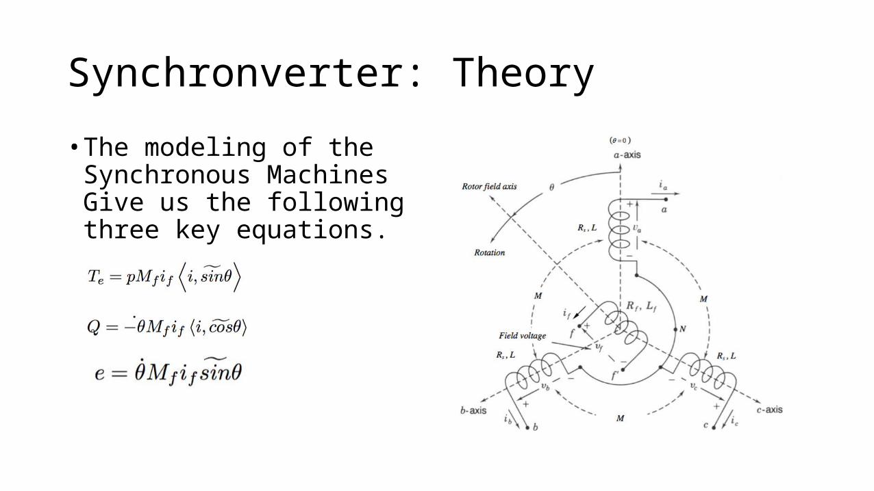
Synchronverter: Theory• The modeling of the
Synchronous Machines Give us the following three key equations.
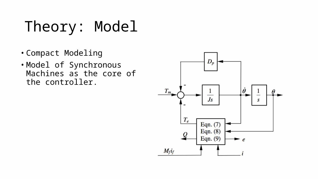
Theory: Model• Compact Modeling• Model of Synchronous Machines as
the core of the controller.
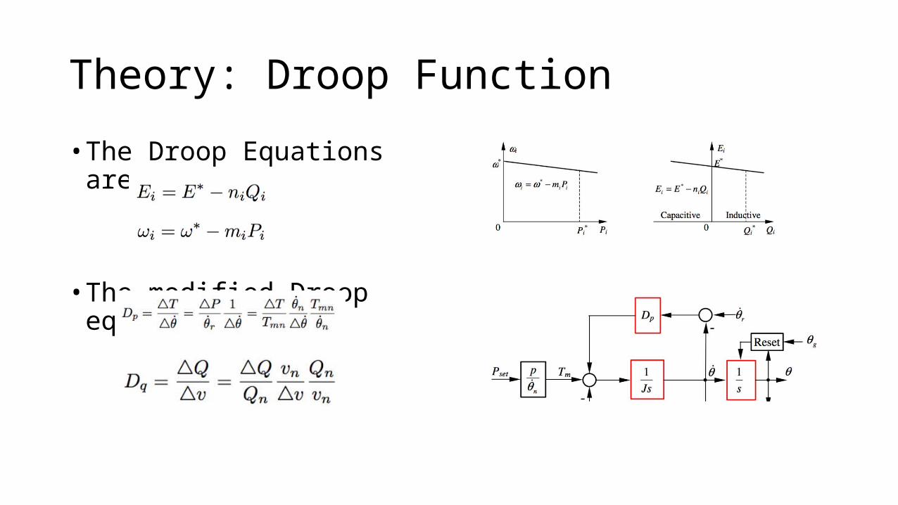
Theory: Droop Function• The Droop Equations are
• The modified Droop eqns
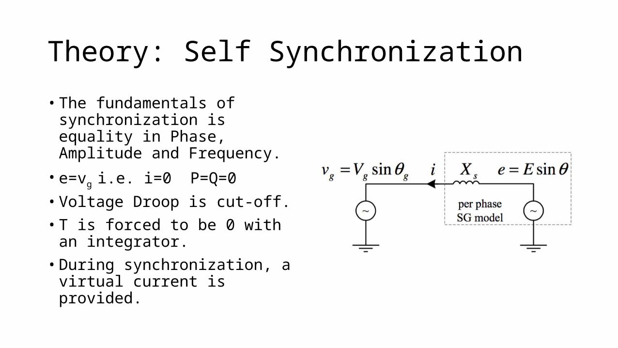
Theory: Self Synchronization• The fundamentals of synchronization
is equality in Phase, Amplitude and Frequency.• e=vg i.e. i=0 P=Q=0• Voltage Droop is cut-off.• T is forced to be 0 with an integrator.• During synchronization, a virtual
current is provided.
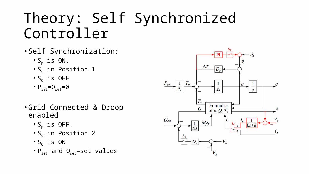
Theory: Self Synchronized Controller• Self Synchronization:
• Sp is ON.• Sc in Position 1• SQ is OFF• Pset=Qset=0
• Grid Connected & Droop enabled• Sp is OFF.• Sc in Position 2• SQ is ON• Pset and Qset=set values

Project DefinitionDetails of the Project

Our Project: Model
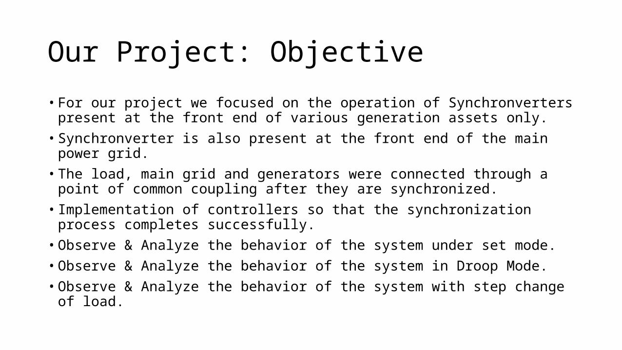
Our Project: Objective• For our project we focused on the operation of Synchronverters present at the
front end of various generation assets only.• Synchronverter is also present at the front end of the main power grid.• The load, main grid and generators were connected through a point of common
coupling after they are synchronized.• Implementation of controllers so that the synchronization process completes
successfully.• Observe & Analyze the behavior of the system under set mode.• Observe & Analyze the behavior of the system in Droop Mode.• Observe & Analyze the behavior of the system with step change of load.

Our Project: Achievement• The project was divided into 2 stages.• Build the system using constant 400 V DC sources and synchronize using PLL’s• After this was achieved we added the self synchronization mechanism• A solar farm was made and added to the system• A wind farm was also made however due to computational constraints it was
removed.• Simulation results were recorded and analyzed for set mode, droop mode and
with step change of the load.
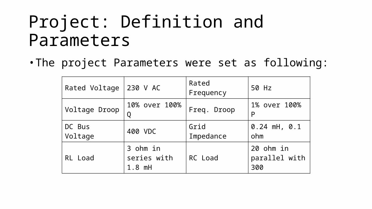
Project: Definition and Parameters• The project Parameters were set as following:
Rated Voltage 230 V AC Rated Frequency 50 Hz
Voltage Droop 10% over 100% Q Freq. Droop 1% over 100% P
DC Bus Voltage 400 VDC Grid Impedance 0.24 mH, 0.1 ohm
RL Load 3 ohm in series with 1.8 mH RC Load 20 ohm in parallel
with 300
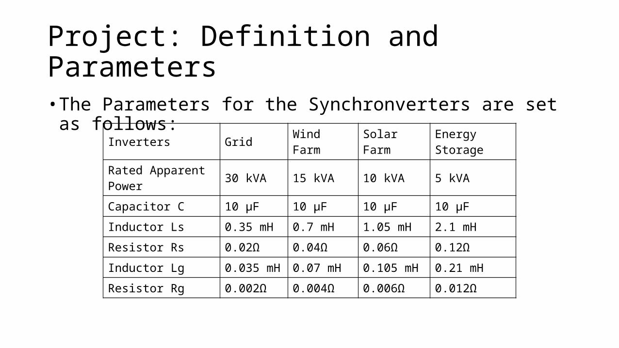
Project: Definition and Parameters• The Parameters for the Synchronverters are set as follows:
Inverters Grid Wind Farm Solar Farm Energy Storage
Rated Apparent Power 30 kVA 15 kVA 10 kVA 5 kVA
Capacitor C 10 µF 10 µF 10 µF 10 µF
Inductor Ls 0.35 mH 0.7 mH 1.05 mH 2.1 mH
Resistor Rs 0.02Ω 0.04Ω 0.06Ω 0.12Ω
Inductor Lg 0.035 mH 0.07 mH 0.105 mH 0.21 mH
Resistor Rg 0.002Ω 0.004Ω 0.006Ω 0.012Ω

SimulationMATLAB Models and Details
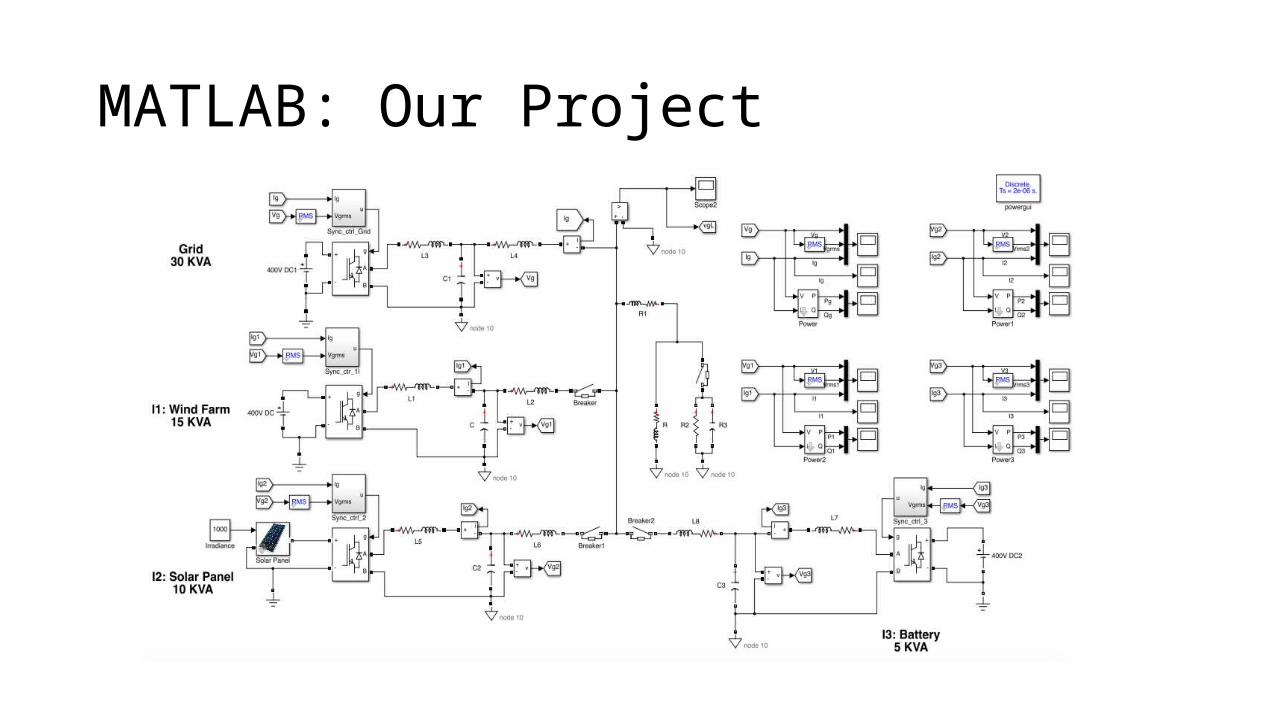
MATLAB: Our Project
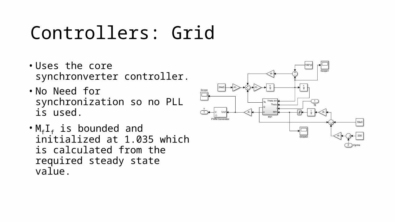
Controllers: Grid• Uses the core synchronverter
controller.• No Need for synchronization so no PLL
is used.• MfIf is bounded and initialized at 1.035
which is calculated from the required steady state value.
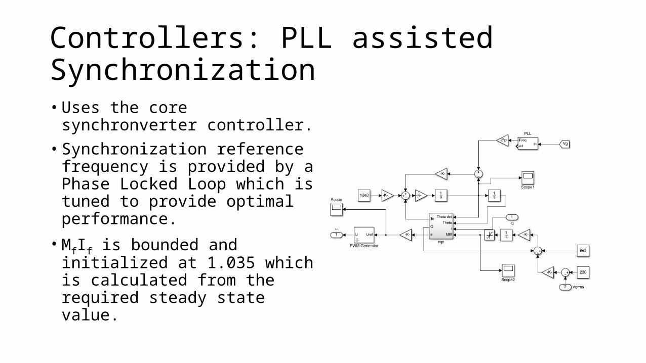
Controllers: PLL assisted Synchronization• Uses the core synchronverter
controller.• Synchronization reference frequency
is provided by a Phase Locked Loop which is tuned to provide optimal performance.• MfIf is bounded and initialized at 1.035
which is calculated from the required steady state value.
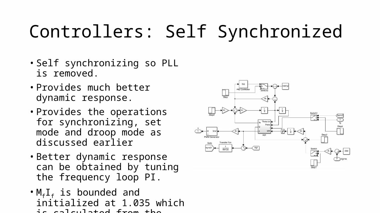
Controllers: Self Synchronized• Self synchronizing so PLL is removed.• Provides much better dynamic
response.• Provides the operations for
synchronizing, set mode and droop mode as discussed earlier• Better dynamic response can be
obtained by tuning the frequency loop PI.• MfIf is bounded and initialized at 1.035
which is calculated from the required steady state value.
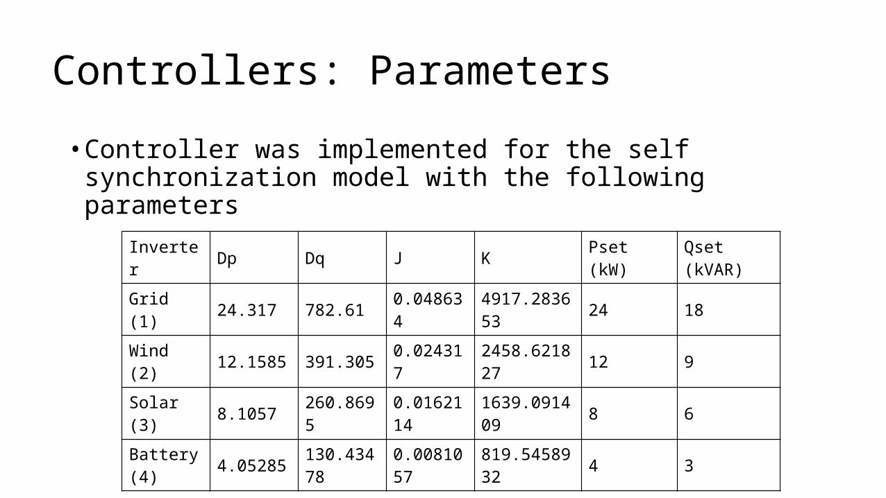
Controllers: Parameters• Controller was implemented for the self synchronization model with
the following parameters
Inverter Dp Dq J K Pset (kW) Qset (kVAR)
Grid (1) 24.317 782.61 0.048634 4917.283653 24 18
Wind (2) 12.1585 391.305 0.024317 2458.621827 12 9
Solar (3) 8.1057 260.8695 0.0162114 1639.091409 8 6
Battery (4) 4.05285 130.43478 0.0081057 819.5458932 4 3

Renewable SourcesModels and Details
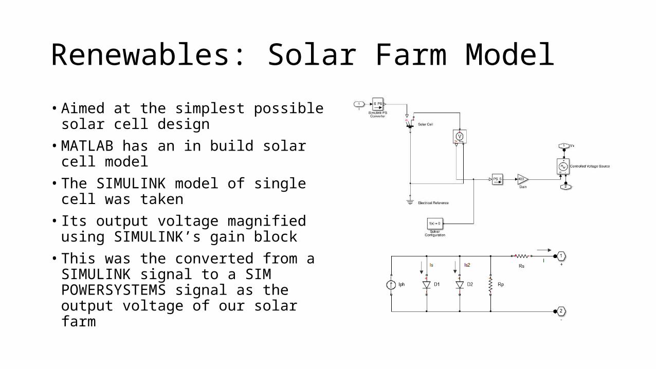
Renewables: Solar Farm Model• Aimed at the simplest possible solar
cell design• MATLAB has an in build solar cell model• The SIMULINK model of single cell was
taken• Its output voltage magnified using
SIMULINK’s gain block• This was the converted from a
SIMULINK signal to a SIM POWERSYSTEMS signal as the output voltage of our solar farm
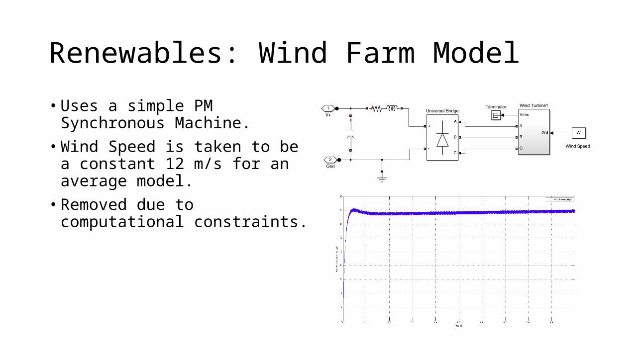
Renewables: Wind Farm Model• Uses a simple PM Synchronous
Machine.• Wind Speed is taken to be a constant
12 m/s for an average model.• Removed due to computational
constraints.

Experimental ResultsGraphs!

Experimental Results: Frequency
Response with PLL Response with Self Synchronization

Experimental Results: V-I output of wind FarmResponse with PLL Response with Self Synchronization

Experimental Results: V-I output of smaller InvertersResponse for Solar Response for Battery
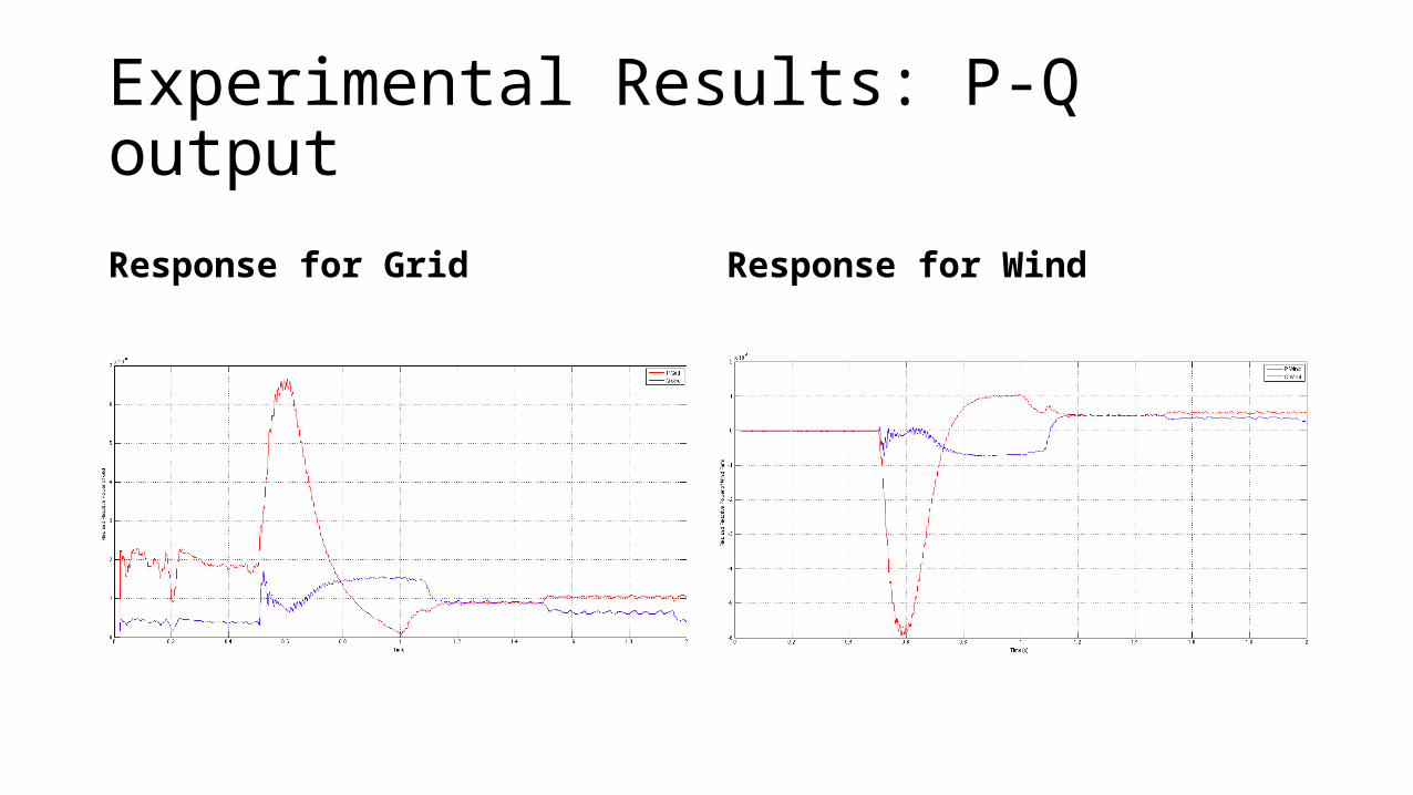
Experimental Results: P-Q output
Response for Grid Response for Wind

Experimental Results: P-Q output
Response for Solar Response for Battery
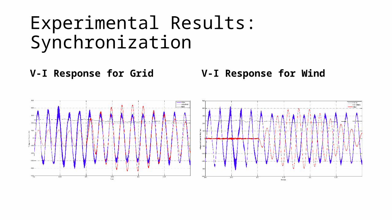
Experimental Results: SynchronizationV-I Response for Grid V-I Response for Wind
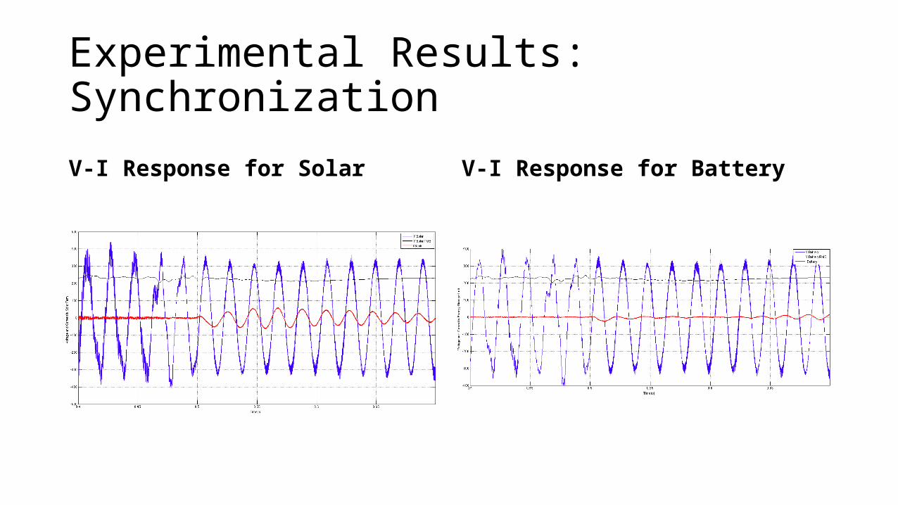
Experimental Results: SynchronizationV-I Response for Solar V-I Response for Battery

Experimental Results: Droop ResponseV-I Response for Grid V-I Response for Wind
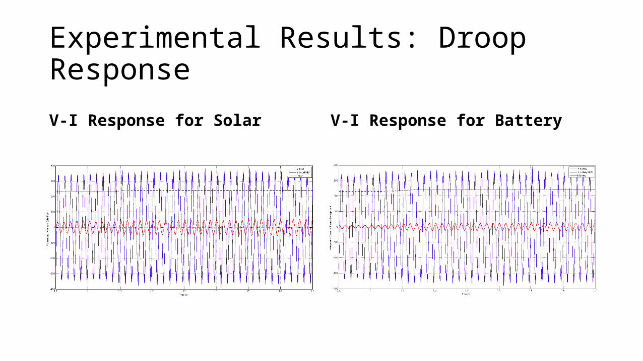
Experimental Results: Droop ResponseV-I Response for Solar V-I Response for Battery
Summary• 4 Synchronverters were modeled and experimented on to make a
microgrid.• Two approaches were adapted and compared• PLL• Self Synchronization
• Dynamic models for Solar Panels and wind turbines were adopted, however only solar model was used.

Thank You!
Questions?