design of sustainable reinforced concrete structures ... papers/data/e332.pdf · design of...
TRANSCRIPT
Design of Sustainable Reinforced Concrete Structures Assisted by Numerical Simulations
Cervenka Jan1, Pukl Radomir1 and Cervenka Vladimir1
1Cervenka Consulting Ltd
Na Hrebenkach 55, 15000 Praha 5, Czech Republic, [email protected]
ABSTRACT
Sustainability of concrete structures can be ensured by deployment of high-tech design tools such as numerical simulations. Namely, in existing structures an improved assessment can reveal reserves in structural capacity and justify a safe and economical service under environmental conditions. Assessment of sustainability was recently performed to existing nuclear power plants where stress tests were performed in order to check safety in more demanding design requirements. The benefits of numerical simulations in design are described and its applicability is demonstrated on two case studies. One case is in the assessment of seismic resistance based on a pushover analysis of existing old nuclear power plant in Switzerland. Other case is a design of grouted connections in offshore wind towers with UHPC concrete material. It is demonstrated, that numerical simulation is well substantiated in cases of complex structures, where an unsafe design has a large impact on environment.
Keywords. Numerical simulation, non-linear analysis, damage, cracking, safety formats.
INTRODUCTION
Requirements of sustainability are driven by environmental concern substantiated by a huge volume of concrete cast all over the world as a result of industrial growth. Any improvement in efficiency of design can contribute to this goal. Authors have been involved in development of new design techniques based on information technologies, namely, numerical simulations, which can bring better expertise to the design process by exploiting advances in material engineering and computational mechanics.
Application of numerical simulations have been recently included in the fib New Model Code 2010 (Walraven, 2012) where the appropriate safety formats are proposed for this purpose. This concept can be applied in design practice and can offer advanced and rational solutions to modern structural technologies. A question of sustainability was recently addressed to existing nuclear power plants where stress tests were performed in order to check safety in more demanding design requirements.
The paper introduces the features of numerical simulations based on non-linear finite element analysis and its potential for design practice. Its applicability are demonstrated on
two case studies. One is in the assessment of seismic resistance of existing old nuclear power plant in Switzerland based on a pushover method of analysis. Other example is a design of grouted joints in offshore wind towers with UHPC concrete material. It is demonstrated, that a numerical simulation is well substantiated in cases of complex structures, or in nuclear power plants where an unsafe design has a large impact on the environment.
NON-LINEAR ANALYSIS
Design of concrete structures in engineering practice is based on a linear elastic structural analysis and a check of cross sections. This approach is based on a partial safety factors (PSF) with a local safety format. The partial safety format defines the safety for input variables, but a safety of the global resistance is not verified. The partial safety format is based on a random variation of basic variables, such as concrete strength, but the random variation of global resistance is not checked. The PSF format was developed for the design method based on linear elastic analysis, which does not allow a realistic assessment of global resistance in an ultimate limit state. An obvious advantage of the elastic analysis is that it allows a superposition of results of various load cases. However, the process is basically inconsistent since the check of the ultimate limit states of cross sections assumes non-linear constitutive relations while the analysis of internal force is based on elastic material behavior. Nevertheless, this approach is widely used in most design codes and is validated by many years of experience. It is also a background method for most design software tools.
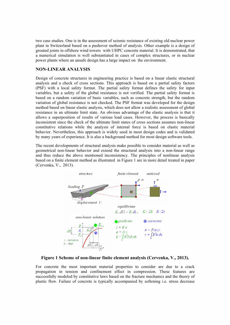
The recent developments of structural analysis make possible to consider material as well as geometrical non-linear behavior and extend the structural analysis into a non-linear range and thus reduce the above mentioned inconsistency. The principles of nonlinear analysis based on a finite element method as illustrated in Figure 1 are in more detail treated in paper (Cervenka, V., 2013).
Figure 1 Scheme of non-linear finite element analysis (Cervenka, V., 2013).
For concrete the most important material properties to consider are due to a crack propagation in tension and confinement effect in compression. These features are successfully modeled by constitutive laws based on the fracture mechanics and the theory of plastic flow. Failure of concrete is typically accompanied by softening i.e. stress decrease

under applied deformation. The failure of concrete has a distinct discrete character. These phenomena are in terms of finite element model approximated by strain localization within a band of finite elements as illustrated in Figure 2. Since a detail treatment of the constitutive modeling of concrete structures is beyond the scope of this paper we refer to (Cervenka et al., 2008) for more extensive information.
Figure 2 Cracks band with strain locatization (Cervenka, V., 2013).
GLOBAL SAFETY FORMAT
Advances in numerical structural analysis open new possibilities for a more realistic analysis of concrete structures. As a consequence a new safety format for non-linear analysis emerged. The specialty of safety format for non-linear analysis originates from its global nature. In non-linear analysis, the resistance is verified on a global structural level (for example a resistance of a bridge against the traffic load) and not in local sections. A local check is in non-linear analysis fulfilled implicitly by material laws. The safety should be checked globally, for the whole structure. However, an adequate global safety verification was not available in present codes and a guideline for a global safety check was lacking. Recently, the fib Model code 2010 (Walraven, 2012) introduced a verification assisted by numerical simulations and a concept of global safety format.
The condition for verification of safety in ultimate limit state is defined as , where
is design action and dF R d
dF dR is design resistance and both these entities cover safety
margins. In nonlinear analysis dR describes a global resistance (e.g. set of resisting forces to
a live load, horizontal load, etc.) and reflects an integral response of the whole structure, in which all material points (or cross sections) interact. The safety covered in design resistance
can be expressed by /d m RR R , where mR is the mean resistance and the global safety
factor R covers all uncertainties involved in the resistance estimate. Considering the
resistance independently of loading, the sources of these uncertainties are due to a random nature of material properties, geometry and resistance models. Consequently, the global safety factor (or briefly, safety factor of resistance) can be directly related to the uncertainties due to random models (Cervenka, V., 2008). Assuming a log-normal model of random distribution function the safety factor can be expressed as
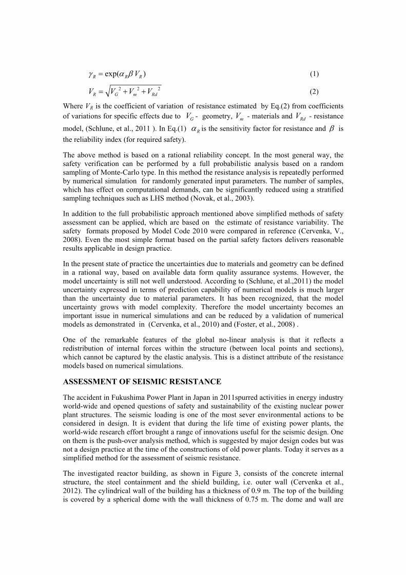
exp( )R R V R (1)
2 2R G m RdV V V V 2 (2)
Where VR is the coefficient of variation of resistance estimated by Eq.(2) from coefficients of variations for specific effects due to - geometry, - materials and - resistance
model, (Schlune, et al., 2011 ). In Eq.(1) GV mV RdV
R is the sensitivity factor for resistance and is
the reliability index (for required safety).
The above method is based on a rational reliability concept. In the most general way, the safety verification can be performed by a full probabilistic analysis based on a random sampling of Monte-Carlo type. In this method the resistance analysis is repeatedly performed by numerical simulation for randomly generated input parameters. The number of samples, which has effect on computational demands, can be significantly reduced using a stratified sampling techniques such as LHS method (Novak, et al., 2003).
In addition to the full probabilistic approach mentioned above simplified methods of safety assessment can be applied, which are based on the estimate of resistance variability. The safety formats proposed by Model Code 2010 were compared in reference (Cervenka, V., 2008). Even the most simple format based on the partial safety factors delivers reasonable results applicable in design practice.
In the present state of practice the uncertainties due to materials and geometry can be defined in a rational way, based on available data form quality assurance systems. However, the model uncertainty is still not well understood. According to (Schlune, et al.,2011) the model uncertainty expressed in terms of prediction capability of numerical models is much larger than the uncertainty due to material parameters. It has been recognized, that the model uncertainty grows with model complexity. Therefore the model uncertainty becomes an important issue in numerical simulations and can be reduced by a validation of numerical models as demonstrated in (Cervenka, et al., 2010) and (Foster, et al., 2008) .
One of the remarkable features of the global no-linear analysis is that it reflects a redistribution of internal forces within the structure (between local points and sections), which cannot be captured by the elastic analysis. This is a distinct attribute of the resistance models based on numerical simulations.
ASSESSMENT OF SEISMIC RESISTANCE
The accident in Fukushima Power Plant in Japan in 2011spurred activities in energy industry world-wide and opened questions of safety and sustainability of the existing nuclear power plant structures. The seismic loading is one of the most sever environmental actions to be considered in design. It is evident that during the life time of existing power plants, the world-wide research effort brought a range of innovations useful for the seismic design. One on them is the push-over analysis method, which is suggested by major design codes but was not a design practice at the time of the constructions of old power plants. Today it serves as a simplified method for the assessment of seismic resistance.
The investigated reactor building, as shown in Figure 3, consists of the concrete internal structure, the steel containment and the shield building, i.e. outer wall (Cervenka et al., 2012). The cylindrical wall of the building has a thickness of 0.9 m. The top of the building is covered by a spherical dome with the wall thickness of 0.75 m. The dome and wall are

connected through a pre-stressed reinforced concrete ring with 14 pre-stressing tendons. There are no pre-stressing tendons in the wall or in the dome. The interior of the building is covered by 6 mm of steel liner (leakage shield). All these elements were included in a three-dimensional model, which was analyzed by finite element simulation software ATENA (Cervenka et. al. 2011). This program can consider all important features of reinforced concrete behavior such as concrete cracking, crushing, reinforcement yielding and rupture (Cervenka & Pappanikolaou 2008). The three-dimensional model of the shield building was created using three-dimensional shell elements (Jendele & Cervenka, 2009). The numerical models consisted of the dome, the reinforcing ring with pre-stressing cables and the cylindrical wall. In addition, the steel liner that is attached to the internal surface of the shield building was considered as well, Figure 3. For the safety assessment two models were considered. The „Median model“ is using median, i.e. average material properties and the „Characteristic model“ with properties of the 5% quantile properties. The finite element model and the shape of the applied horizontal pushover force are shown in Figure 4 The shape of the pushover force distribution is based on a fundamental frequency considering the foundation-structure interaction.
Figure 3 Geometry of the reactor building.
A typical deformed shape and crack pattern obtained from the semi-static pushover analysis are shown in Figure 5.

Figure 4 FE model of containment (left). Shape of horizontal pushover force distribution (right) .
Figure 5 Deformed form (left) and crack pattern (right) of the characteristic analysis case.
The pushover curve was calculated up to the point when the base shear force dropped below at least 80% of the peak load, see Figure 6. The pushover curves are transformed into the acceleration displacement diagram, which allows their comparison with the local seismic demand, which is defined by the elastic response spectrum. The figure shows that the displacement capacities for the idealized bilinear pushover curves are 233 mm for median analysis and 133 mm for characteristic analysis. This is to be compared with the seismic demand, which would be 22 mm for the medium and 13 mm for the characteristic analysis. This result shows very high seismic safety. Furthermore, the idealized curves will be used by the plant owner for a more detailed semi-probabilistic analysis and for the calculation of the fragility curves.

Figure 6 Pushover curves based on elastic response spectrum of the local seismic demand.
The results confirmed the seismic safety of this old power plant. Two pushover curves were calculated for the estimation of median and characteristic response. Analogical approach is also applied for the seismic evaluation of other buildings in the nuclear power plant complex.
GROUTED CONNECTIONS IN OFFSHORE STRUCTURES
Offshore wind farms appear as a fast growing industry in response for demand of renewable energy sources and sustainable environmental conditions. The wind turbines are installed on the top of offshore steel structures located on the sea bed, Figure 7. A tower superstructure is fixed to the foundation piles using technology of grouted connections, in which the ultra high performance concrete (UHPC) is used as a grout material. In this technology the grout is subjected to extremely high load actions, which should be verified by design.
Figure 7 Offshore wind farm.
The grout material has a high strength comparable to steel, but exhibits brittleness and fatigue sensitivity. Therefore, the design of grouted connection is aided by numerical

simulations in which real properties of grout material obtained from laboratory tests are utilized. An example of the joint is shown in Figure 8.
pin
grout
pile
Figure 8 Examples of connection between pin and pile of a tower.
Figure 9 Damage of grout showing a crack pattern on surface (left) and in a cross section (right).

A damage by cracks of the grout under imposed loading is illustrated in Figure 9. Nonlinear analysis is performed for all severe actions including effects of fatigue, which is one of the most important effects to be considered in the wind turbine design. With the help of numerical simulations a optimization of the joint dimensions and material properties can be
structural solution meeting requirements of
d simulation tools
tance models and should be used format. The model uncertainty of numerical models of by model validations.
of the paper was partly developed within the project supported by Foundation P105/12/2051.
ervenka, V., Jendele, L., Cervenka, J. (2011). “ATENA Program Documentation, Part 1,
efficiently performed resulting in a reliable sustainability.
CONCLUDING REMARKS
A numerical simulation based on nonlinear finite element analysis has been used for verification of structural performance in energy production industry, namely in assessment of existing old nuclear power plants and in the wind farms. The advancemeet challenges of high structural complexity and extreme load actions and offer an exploitation of state-of-the-art numerical techniques and material models.
The numerical simulation represents an advanced resisalong with the global safetyresistance should be determined
ACKNOWLEDGEMENT
Theoretical background the Czech Science
REFERENCES
CTheory“, Cervenka Consulting, Ltd., Prague 2011, www.cervenka.cz Cervenka, V. (2013). “Reliability-based non-linear analysis according to Model Code 2010.”
einforced Concrete Beams: PART II – Assessment of Global Safety of Resistance". Proc. 3rd
., Pappanikolaou, V. (2008) “Three dimensional combined fracture-plastic material model for concrete.” Int. J. of Plasticity, Vol. 24, 12, 2008, ISSN 0749-6419, pp.
Cervenka, V. (2008), “Global Safety Format for Nonlin
einforced Concrete Beams: PART II – Assessment of Global Safety of Resistance". Proc. 3rd
Cervenka, J., Proske, D., Kurmann, D., Cervenka, V. (2012). “Pushover Analysis of Nuclear
Journal of fib, Structural Concrete 14 (2013), No. 1 Cervenka, V., Dolezel, J., Novak, D, (2010). "Shear Failure of Large Lightly R
fib International Congress – 2010, May 29-June 2, 2010, Washington DC, USA.
Cervenka, J
2192-2220.
ear Calculation of Reinforced Concrete”. Beton- und Stahlbetonbau 103 (2008), Special Edition, Ernst&Sohn. Pp37-42
Cervenka, V., Dolezel, J., Novak, D, (2010). "Shear Failure of Large Lightly R
fib International Congress – 2010, May 29-June 2, 2010, Washington DC, USA.
Power Plant Structures”. Proceedings of fib Symposium, Stockholm, 11-14 June 2012.

Foster, S., Maekawa, K., Vecchio, F. (2008). ”Practitioners’ guide to finite element modelling of reinforced concrete structures.” State-of-the-art report by FIB Task Group 4.4. Bulletin no.45, June 2008. ISBN 987-3-88394-085-7.
Jendele, L., Cervenka, J. (2009) “Three-dimensional Implementation of the Ahmad Shell
Novak, D., Vorechovsky, M., Rusina, R. (2003). “Small-sample Probabilistic Assessment -
llpress,
“Safety Formats for Nonlinear Analysis of Concrete Structures. “ Engineering Structures , Elsewier, Vol.33,No.8,August 2011.
Walraven, J. (2012). “Model Code 2010. Final draft. Volume 1 and 2.” March 2012. fib ulletin 65 and 66. ISBN 978-2-88394-105-2
Element: Derivation and Performance Assessment”, Civil, Structural and Environmental Engineering Computing, B.H.V. Topping, L.F. Costa Neves and R.C. Barros, (Editors), Civil-Comp Press, Stirlingshire, Scotland, 2009, paper 288,.
software FREET“. ICASP 9, 9th International Conference on Applications of Statistics and Probability in Civil Engineering, San Francisco, USA, July 6-9, 2003, pp. 91-96 MiRotterdam, ISBN 90-5966-004-8.
Schlune, H., Plos, M., Gylltoft, K. (2011).
B