design of structures for missile impactfrom missile impact are included in the report. the...
TRANSCRIPT
BC-T0P-9A Revision 2
SEPTEMBER 1974
TOPICAL REPORT
DESIGN OF STRUCTURES FOR MISSILE IMPACT
MASTER Bechtel Power Corporation San Francisco, California
,U: -IN'>; 'H4„
DISCLAIMER
This report was prepared as an account of work sponsored by an agency of the United States Government. Neither the United States Government nor any agency Thereof, nor any of their employees, makes any warranty, express or implied, or assumes any legal liability or responsibility for the accuracy, completeness, or usefulness of any information, apparatus, product, or process disclosed, or represents that its use would not infringe privately owned rights. Reference herein to any specific commercial product, process, or service by trade name, trademark, manufacturer, or otherwise does not necessarily constitute or imply its endorsement, recommendation, or favoring by the United States Government or any agency thereof. The views and opinions of authors expressed herein do not necessarily state or reflect those of the United States Government or any agency thereof.

DISCLAIMER Portions of this document may be illegible in electronic image products. Images are produced from the best available original document.

TOPICAL REPORT
BC-TOP-9-A
Revision 2
DESIGN OF STRUCTURES FOR MISSILE IMPACT
PREPARED BY:
R. B. Linderman J. V. Rotz G. C. K. Yeh
APPROVED BY:
W. A. Brandes U y f a / U ^ a ^ ^ ^
H. W. Wahl
BECHTEL POWER CORPORATION Issue Date: September 1974

BC-T0P-9-A Rev. 2
•
CAVEAT: THIS REPORT HAS BEEN PREPARED BY AND FOR THE USE OF BECHTEL POWER CORPORATION AND ITS RELATED ENTITIES. ITS USE BY OTHERS IS PERMITTED ONLY ON THE UNDERSTANDING THAT THERE ARE NO REPRESENTATIVES OR WARRANTIES, EXPRESS OR IMPLIED, AS TO THE VALIDITY OF THE INFORMATION OR CONCLUSIONS CONTAINED HEREIN.

UNITED STATES
ATOMIC ENERGY COMMISSION WASHINGTON, D.C. 20545
Mr. John V. Morowski Vice President-Engineering Bechtel Power Corporation Fifty Beale Street San Francisco, California 94119
Dear Mr. Morowski:
The Regulatory staff has completed its review of Bechtel Power Corporation's Topical Report, BC-TOP-9, Revision 2, dated September 1974 and entitled "Design of Structures for Missile Impact". We conclude that the design criteria and procedures described by this report are acceptable to the Regulatory staff and that BC-TOP-9, Revision 2, is acceptable by reference in applications for construction permits and operating licenses. A summary of our evaluation is enclosed.
BC-TOP-9 does not provide all of the pertinent information required by the Regulatory staff in its review of specific applications. Therefore, the appropriate supplementary information identified in the Regulatory Position of the enclosed Topical Report Evaluation will have to be provided in individual Safety Analysis Reports.
The staff does not intend to repeat its review of BC-TOP-9, Revision 2, when it appears as a reference in a particular license application. Should Regulatory criteria or regulations change, such that our conclusions concerning BC-TOP-9, Revision 2, are invalidated, you will be notified and given the opportunity to revise and resubmit your topical report for review, should you so desire.

ftijv «s 'J )374 Mr. John V. Morowski - 2 -
We request that you reissue BC-TOP-9, Revision 2, dated September 1974 in accordance with the provisions of the "Elements of the Regulatory Staff Topical Report Review Program" which was forwarded to you on August 26, 1974. If you have any questions in this regard, please let us know.
Sincerely,
'R. W. Klecker, Technical Coordinator for Light Water Reactors Group 1
Directorate of Licensing
Enclosure: Topical Report Evaluation

Topical Report tvaluation
Report: BC-TOP-9 Rev.2 Report Title: Design of Structures for Missile Impact Report Date: September 1974 Originating Organization: Bechtel Power Corporation Reviewed by: Structural Engineering Branch, November 1974
Summary of Report
This report contains the current general procedures and criteria
used by Bechtel Power Corporation for design of nuclear power
plant structures and components against the effects of impact of
missiles. The report covers the evaluation of local effects due to
missiles impacting on both concrete and steel structural elements.
It also covers the procedures used to evaluate the overall structural
response to missile impact loads. Design guidelines related to use
of dynamic capacity increase factors, allowable ductility ratio and
allowable range of steel ratios used in concrete structural elements
are also discussed in the report. Brief discussionsof special
problems related to (a) force-time history for automobile crash and
(b) penetration of a missile through a liquid are included as a
part of the report.
The formulae which can be used to predict the penetration resulting
from missile impact are included in the report. The penetration and
perforation formulae assume that the missile strikes the target normal
to the surface, and the axis of the missile is assumed parallel to
the line of flight. These assumptions result in a conservative
estimate of local damage to the target. The formula used to predict
Lhe penetration is the Modified Petry equation, while that for per-
foration and spalling is the Ballistic Research Laboratory formula mod-
ified to allow its use for concrete strength other than 3000 psi
by replacing the constant coefficient 7.8 by 427/f/ f . The wall
thicknesses to prevent perforation and spalling are that calculated
using the Ballistic Research Laboratory formula multiplied by factors
of 1.25 and 2.5, respectively. The Ballistic Research Laboratory
formula for steel is used to predict design thickness requirement

-2-
for steel targets. The thicknesses of steel targets to prevent
perforation are obtained by multiplying 1.25 by the thicknesses
for threshold perforation as determined by the BRL formula.
The report discusses both elastic and plastic modes of overall
structural response of target subjected to a missile impact.
Expressions for (a) velocities of missile and target after impact,
(b) strain energy of a target required to stop a missile after
impact, (c) target effective mass definition and (d) resistance
functions for various target configurations are presented in the
report. The overall structural response of a target is determined
by equating the available target strain energy to the required strain
energy to stop a missile. The resistance function for a structural
element is determined using yield-line theory for concentrated loads
impacting steel and reinforced concrete beam and slab. The allowable
ductility ratios to be used for design are based on the available data
from the literature accepted in the engineering practice. However the
governing requirement for an overall structural response design con-
sideration is that the maximum deflection of the target shall be
limited so as not to impair the function of other safety related
equipment. Due to the complexity of the impact phenomena, the target
effective mass is conservatively derived based on the tests performed
on concrete slabs and beams.
The report covers two types of special problems, i.e., determination
of an empirical formula for force-time history of automobile crash
and an evaluation of a missile velocity as it passes through a liquid.
In deriving the force-time history of an automobile crash under frontal
Impact, the automobile is considered as a deformable missile and the
structure a rigid target. The pertinent equations are based on
theoretical considerations backed by experimental data.

-3-
The^derivation of the velocity of a missile after it has penetrated
through a liquid takes into consideration the buoyant force, which is
variable during the process of immersion of the missile and constant
after the entire missile is immersed in the liquid, and drag force
which may be considered as constant for any particular set of con-
ditions. The non-linear, second order, non homogeneous differential
equation is transformed into a linear differential equation which
is solved by applying pertinent boundary conditions.
For the postulated missiles and their properties as well as for
structures, shields and barriers that are required to be designed
against effects of missile impact, the report refers to the plant
SAR.
Appendix A provides the cross reference between sections of the AEC's
Standard SAR format and the sections, of BC-TOP-9. Glossary of the
report is given in Appendix B. A review of existing design formulas
is given in Appendix C whereas Appendix D discusses theoretical der-
ivation for force-time history associated with automobile crash
and velocity of a missile penetrating through a liquid. Sample
applications of the procedures presented in the report are shown in
Appendix E with references and bibliography listed in Appendix F.
Summary of the Regulatory Evaluation
The Structural Engineering Branch of the Directorate of Licensing
has reviewed the subject report and its appendices. The procedures
covered by this report with the qualifications stated in the follow-
ing Regulatory Position and augmentation of pertinent information
that is referred to and to be provided in the plant SAR are judged to
represent the present "state of the art" in the field of design of
structures and components against missile impacts. If properly
utilized in nuclear power plant structural design work, the pro-
cedures and criteria contained in the report should provide

-4-
conservative and acceptable bases for design of structural elements
against missile impact effects.
Regulatory Position
The design criteria and procedures are acceptable to the Regulatory
staff. The report may be referenced in future case applications
provided that the following specific information reviewed and
accepted by the Regulatory staff is included in individual SAR:
a) Parameters that define the postulated missiles such as striking
velocity, weight, missile configurations and impacting area, etc.
b) Structures, shields and barriers that are required to be designed
for missiles with their pertinent characteristics.
c) If use of a ductility ratio greater than 10 (i.e., \i> 10) is required to demonstrate design adequacy of structural elements
against missile impact, such a usage should be identified in the
plant SAR. Information justifying the use of this relatively high
ductility value may become necessary for inclusion in the plant
SAR. In such a case, the Regulatory staff will request the
applicant to provide the information on a case by case basis.
d) The evaluation of punching shear effect due to impact of uncon-
ventional missiles, is not included as a part of the overall
structural response consideration in the report. The subject
should be adequately addressed in individual plant SAR.
BC-T0P-9-A Rev. 2
ABSTRACT
This report contains methods and procedures for evaluating the effects of missile impact on structures. A means to evaluate the change of velocity of a missile passing through a liquid is also included. Missile impact effects on structures are evaluated in terms of local damage (penetration, perforation, and spalling) and structural response. Empirical formulae are used to evaluate local effects. Structural dynamic principles are use to evaluate structural response.
ACKNOWLEDGMENT
This document is the result of a joint effort on the part of several contributors.
The following is a chronological account of major participants contrib-uting to the development of this document:
Revision 0 (issued October, 1972) was prepared by M. Fakhari, B. Linderman, J. Rotz and M. Suarez and approved by A. J. Bingaman (Gaithersburg Office Chief Civil Engineer) and D. W. Halligan (Power and Industrial Division Chief Civil Engineer).
Revision 1 (issued July, 1973) was prepared by R. B. Linderman, M. Fakhari, J. V. Rotz, E. Thomas, G. A. Tuveson, and G. C. K. Yeh; and approved by W. A. Brandes (Los Angeles Power Division, Chief Civil Engineer) and L. G. Hinkelman (Thermal Power Organization, Chief Civil Engineer); Technical Consultant, N. M. Newmark.
Revision 2 (issued September, 1974) was prepared by R. B. Linderman, J. V. Rotz and G. C. K. Yeh; and approved by W. A. Brandes (Los Angeles Power Division, Chief Civil Engineer).and H. W. Wahl (Thermal Power Organization, Chief Civil Engineer); Technical Consultant, N. M. Newmark.

BC-T0P-9-A Rev. 2
CONTENTS
Section
1. INTRODUCTION
Title
1.1 General 1.2 Approach 1.3 Missile Characteristics 1.4 Target Characteristics
Page
1-1
1-1 1-1 1-2 1-2
2. LOCAL EFFECTS
2.1 Reinforced Concrete Targets 2.1.1 Penetration 2.1.2 Perforation 2.1.3 Spalling 2.2 Steel Targets 2.3 Multiple Element Barriers 2.3.1 Reinforced Concrete Barrier 2.3.2 Steel Barrier
2-1
2-1 2-1 2-2 2-3 2-3 2-4 2-5 2-5
3. STRUCTURAL RESPONSE TO MISSILE IMPACT LOAD
3.1 General 3.2 Velocity After Impact 3.3 Required Target Strain Energy Capacity 3.3.1 Elastic Impact 3.3.2 PJastic Impact 3.3.3 Force Time Function Known 3.4 Target Effective Mass 3.5 Structural Response by Energy Balance Method 3.5.1 General Procedures 3.5.2 Elastic Target Response 3.5.3 Elasto-Plastic Target Response 3.5.4 Non-Linear Target Responses
3-1
3-1 3-1 3-2 3-2 3-3 3-3 3-5 3-7 3-7 3-7 3-8 3-9
4. DESIGN GUIDELINES 4-1
4.1 Allowable Stresses and Loadings 4.2 Design Parameters 4.3 Allowable Ductility Ratio
4-1 4-1 4-3
xi

BC-T0P-9-A Rev. 2
CONTENTS (Cont)
Section Title Page
5. SPECIAL PROBLEMS 5-1
5.1 Force-Time History for Automobile Crash 5-1 5.2 Penetration of a Missile Through a Liquid 5-1 5.2.1 Liquid Depth is Less Than or Equal to Missile
Length 5-2 5.2.2 Liquid Depth is Greater Than Missile Length (H > L) 5-2 5.2.3 Definitions of Notations 5-3
X l l
BC-T0P-9-A Rev. 2
LIST OF APPENDICES
Appendix Title Pag
APPENDIX A Cross Reference Listing to AEC Standard SAR Format A-l
APPENDIX B Glossary B-l
APPENDIX C Review of Existing Formulas C-l
APPENDIX D Derivations D-l
APPENDIX E Sample Applications E-l
APPENDIX F References and Bibliography F-l
xiii

BC-T0P-9-A Rev. 2
LIST OF TABLES
Table Title Page
4-1 Dynamic Increase Factor (DIF) 4-4
4-2 Resistance-Yield Displacement Values for Beams 4-5
4-3 Resistance-Yield Displacement Values for
Slabs 4-6
4-4 Ductility Ratios (From Reference 28) 4-7
5-1 Drag Coefficient for Variously Shaped Bodies in Incompressible Flow 5-4
C-l Concrete Penetration, Perforation, and Spalling Formulas C-5
C-2 Perforation in Steel Formulas C-8
xv

BC-T0P-9-A Rev. 2
LIST OF ILLUSTRATIONS
Figure Title Page
2-1 Values of Penetration Coefficient (K ) for Reinforced Concrete 2-6
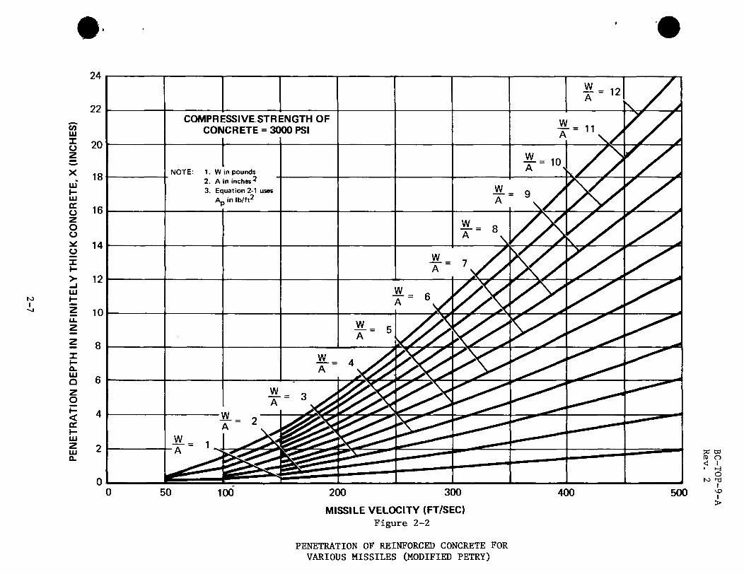
2-2 Penetration of Reinforced Concrete for Various Missiles (Modified Petry) 2-7
2-3 Perforation of Reinforced Concrete for Various Missiles (Ballistics Research Laboratory) 2-8
1 2-4 Penetration, Perforation, and Spalling of
Reinforced Concrete Target by Postulated Tornado Missiles 2-9
3-1 Resistance-Displacement Functions With Associated Structural Response With and Without The Effects of Other Loads 3-12
3-2 Energy-Displacement Functions - Impact Loads Only 3-13
3-3 Energy-Displacement Functions - Impact Combined With Other Loads 3-14
2I 4-1 Coefficients for Moment of Inertia of Cracked
I Sections 4-8
5-1 Penetration of a Missile in a Liquid 5-5
C-l Typical Crater Profiles C-9 C-2 Deleted
2| thru C-22
x v n
BC-T0P-9-A Rev. 2
Section 1
INTRODUCTION
1.1 GENERAL
The design of nuclear power facilities includes the effects of missile impact on structures, systems, and equipment. External building surfaces, interior walls and floors, and special barriers (constructed of concrete and/or steel) that will resist or deflect missiles may be used to protect systems and equipment where necessary.
This report contains methods and preferred procedures to evaluate missile impact on structures and barriers. Missile effects are evaluated in terms of local damage (penetration, perforation, and spalling) and structural response.
Missiles may be generated by an event that is not related to plant operation, or by the failure of plant equipment. The primary sources of missiles, not related to plant operations are debris transported by tornado winds, and falling objects generated by activities near the plant site (such as com-mercial, industrial, or military activities). Missiles that may result from the failure of equipment generally result from the uncontrolled release of energy and forces from a pressurized system or rotating machinery. Missiles that may result from the failure of equipment are fittings, valve parts, various nuts and bolts, and parts of rotating machinery, etc.
1.2 APPROACH
Determining the effect of missile impact is outlined in the following general steps. However, there are many interactive effects in each step that should be considered in the complete analysis.
Determine missile characteristics.
Define target, considering impact in combination with other loads and requirements (preliminary properties).
Determine local effects of missile on target.
Determine target characteristics for structural response and stability.
Determine equivalent target mass during impact.
Determine structural response.
Evaluate structural integrity.
Verify that the maximum deflection does not impair the function of other safety related systems.
1-1

BC-T0P-9-A Rev. 2
1.3 MISSILE CHARACTERISTICS
Missile parameters required for missile impact analysis include trajectory, mass, velocity, geometry, and deformation characteristics. The geometry should include contact area, projected frontal area and variation of area with respect to length. Deformation characteristics include if the missile will deform or is rigid and if it is ductile or brittle. Missile geometry and deformation characteristics have a significant effect on pene-tration or perforation of a target. A pointed missile will penetrate deeper into a target than a blunt missile; it will also perforate a thicker target. Deformation of a missile during impact consumes energy, which results in diminished local damage.
Postulated missiles and their properties may vary with each plant and are defined in the Safety Analysis Report (SAR) for nuclear power plants.
1.4 TARGET CHARACTERISTICS
Structures or barriers (targets), providing missile protection, act as energy absorbers. The target absorbs the energy by local damage at the location of impact (i.e. penetration of the missile into the barrier) and by the structural response of the target.
Local damage depends on missile characteristics, target material properties, and structural response. Empirical methods are used to estimate local damage because of the complex phenomena associated with missile impact. The ability of a target to absorb energy by structural response depends on the dynamic properties of the target, support conditions and other imposed loads at the time of impact. Structural dynamic principles are used to estimate the structural response and determine if the target will remain stable during and after missile impact.
Structures, shields and barriers that are required to be designed for a missile are given in the Safety Analysis Reports.
1-2
BC-T0P-9-A Rev. 2
Section 2
LOCAL EFFECTS
Predicting local damage in the impact area includes estimating depth of penetration, minimum thickness required to prevent perforation, and minimum thickness required to preclude spalling. The penetration and perforation formulae in this section assume that the missile strikes the target normal to the surface, and the axis of the missile is assumed parallel to the line of flight. These assumptions result in a conservative estimate of local damage to the target. Appendix C has information on the more common local effect formula and a discussion of the effects on the penetration for a missile striking a target at oblique angle.
2.1 REINFORCED CONCRETE TARGETS
2.1.1 PENETRATION
The depth to which a rigid missile will penetrate a reinforced concrete target of infinite thickness is estimated by the following formula
12 K A Login P P io
(2-1)
where
X = Depth of missile penetration into concrete element of infinite thickness (inches)
Note: Usually this equation expresses the depth of pene-tration in feet; however, for this document it has been modified to express it in inches.
K = Penetration coefficient for reinforced concrete (see Figure 2-1).
W Missile weight A = -p A Projected frontal area of missile
(psf)
V = Striking velocity of missile (ft/sec). (Limit V £. 1000 ft/sec) s s
This formula is known as the Modified Petry formula.
When the element has a finite thickness the depth of penetration is:
X, 1 + e X, (t > 2X) (2-2)
2-1
BC-T0P-9-A Rev. 2
where
X = Depth of penetration of missile into a concrete element of finite thickness (inches).
e = Base of Napierian Logarithms
t = Thickness of concrete element (inches)
Penetrations for various illustrative examples of missiles are shown in figures 2-2 and 2-4.
2.1.2 PERFORATION
The thickness of a concrete element that will just be perforated by a missile is given by:
V ^ D1'8 ^ 1 0 0 ° ^ where
T = Thickness of concrete element to be just perforated (inches)
W = Weight of missiles (lb)
D = Diameter of missiles (inches)
Note: For irregularly shaped missiles, an equivalent diameter is used. The equivalent diameter is taken as the diameter of a circle with an area equal to the cir-cumscribed contact, or projected frontal area, of the non-cylindrical missile.
V = Striking velocity of missile (ft/sec) s
f = Compressive strength of concrete (psi)
This, formula is known as the Ballistic Research Laboratory, BRL, formula.
The thickness, tp, of a concrete element required to prevent perforation must be greater than T. It is recommended to increase T by 25 percent, but not more than 10 inches, to obtain the t , required to prevent perforation
t = 1.25T § T + 10 (in inches) (2-4) P
2-2
BC-T0P-9-A Rev. 2
The threshold of perforation, T, for various illustrative examples of missiles is shown in figures 2-3 and 2-4.
2.1.3 SPALLING
Spalling of concrete from the side opposite the contact surface of the ele-ment may occur even if the missile will not perforate the element, For an estimate of the thickness that will just start spalling, it is recommended that the following equation be used:
Ts - 2 T (2-5)
where
T = Concrete element thickness that will just start spalling (inches)
T = Concrete thickness to be just perforated (inches). See Equation (2-3)
The thickness, ts, of a concrete element required to prevent spalling must be greater than Ts. It is recommended to increase T by 25 percent, but not more than 10 inches, to prevent spalling.
t = 1.25 T S T + 10 (in inches) (2-6)
2.2 STEEL TARGETS
Steel targets, such as pipes and mechanical equipment vessels, may be per-forated by a missile. Sometimes, protruding elements of a missile may puncture a steel target when the entire missile does not perforate or pass through the target. The minimum contact area of a missile protrusion is used to calculate puncture thickness and the projected area of the entire missile is used to calculate perforation thickness.
The BRL Formula is shown below, modified by setting a material constant K = 1 and solving directly for steel plate thickness, T, which will just be perforated by the missile,
M) 2/3
T * 671B— <2~7>
2-3
BC-T0P-9-A Rev. 2
where
T = Steel plate thickness to just perforate (inches).
M = Mass of the Missile (lb sec2/ft)
W = Weight of the Missile (lb)
V = Striking Velocity of the Missile Normal to Target Surface (ft/sec)
D = Diameter of the Missile (in.)
Note: For irregularly shaped missiles the equivalent diameter is used. The equivalent diameter is taken as the diameter of a circle with an area equal to the circum-scribed contact, or projected frontal area of the non-cylindrical missile.
The thickness, tp, of a steel barrier required to prevent perforation should exceed the thickness for threshold of perforations. It is recommended to increase the thickness, T, by 25 percent to prevent perforation.
tp = 1-25T (2-8)
2.3 MULTIPLE ELEMENT BARRIERS
It may be desirable to construct a missile barrier of several thinner ele-ments, instead of one thick element. Analysis of missile barriers composed of several elements involves determining the residual velocity (Vr) after perforation of one element and using this value for the striking velocity (Vs) on the next element. The following formula is used to determine the residual velocity, Vr (see Appendix C)
V = (v2 - V2) For (V < V ) r \ s p/ p s' (2-9)
V = 0 For (V > V ) r p s
where
V = residual velocity of missile after perforation of an element of thickness t. (fps)
V = striking velocity of the missile normal to target surface (fps)
V = velocity required to just perforate an element (fps)
2-4

BC-T0P-9-A Rev. 2
2.3.1 REINFORCED CONCRETE BARRIER
Combining equations (2-3) and (2-9), the residual velocity of a missile perforating a concrete target is
V = r
vj - vn tD 1.8 a.5 -|l/2
427W 10v (2-10)
where t = thickness of concrete element (inches)
2.3.2 STEEL BARRIER
Combining equations (2-7) and (2-9), the residual velocity of a missile perforating a steel target is
V = r
2 1.12 x 10⁶(Dt)1,5
s " W
1/2
(2-11)
where t = thickness of steel element (inches)
2-5

BC-T0P-9-A Rev. 2
0.0050
0.0040 a
U £ 0.0030 UJ o u Z g 3 0.0020 •— LU z UJ a.
0.0010
0 2,000
0.00276^
3,000 4,000 5,000 6,000
28 - DAY COMPRESSIVE STRENGTH OF CONCRETE
7,000
Figure 2-1
VALUES OF PENETRATION COEFFICIENT (Kp) FOR REINFORCED CONCRETE (Reference 14)
2-6
500
MISSILE VELOCITY (FT/SEC) Figure 2-2
pa w n> o < i • H
O
\o I >
PENETRATION OF REINFORCED CONCRETE FOR VARIOUS MISSILES (MODIFIED PETRY)

200 300 MISSILE VELOCITY (FT/SEC)
Figure 2-3
400 500
PERFORATION OF REINFORCED CONCRETE FOR VARIOUS MISSILES (BALLISTIC RESEARCH LAB)

6-Z
PENE
TRAT
ION
DEP
TH
IN IN
FIN
ITE
THIC
KNES
S CO
NCRE
TE, E
Q. 2-
1 (IN
CHES
)
ui
ai
CONC
RETE
THI
CKNE
SS F
OR T
HRES
HOLD
OF
PERF
ORA
TIO
N, E
Q. 2
3
O
4*
O
O
O
@©
0 CO
-»
-
•©-
•©-
co c
o m
m
m
m
r~
i-
"D
3D
-o
O
m
o -J
co
DO
CO
CO
*.
X _̂
5 u o o -o
r- J>
z A
NJ
O O
r- ro
CO
©0®
&
i CO
NO
en
:
•©-
•©-
CO
c ^
-i m
r- r-
H
3 •<
-o
-o
m
O
^ S
6 _,
I-
o i~
ro
CO
CD J
•©-
CO
H
m
m
i- -u
"O
m
M
00
en
r~
ro
CO
r~
m
CD
m
7>.
D
4* o CO
o
CO
NC
RET
E TH
ICK
NES
S FO
R T
HR
ES
HO
LD O
F S
PA
LLIN
G, E
Q. 2
-5 (
INC
HES
)
Z *A
8£
| V
-6-d
OI-
Dk
•>
Nl

BC-T0P-9-A Rev. 2
Section 3
STRUCTURAL RESPONSE TO MISSILE IMPACT LOAD
3.1 GENERAL
When a missile strikes a target, large forces develop at the missile -target interface, which decelerate the missile and accelerate the target. If the interface forcing function is known, (experimentally determined), the target structure can be modeled mathematically and conventional numeri-cal techniques can be used to predict structural response. For most cases, the forcing function is not known, and a rational method involving energy balance techniques is used to estimate structural response. This involves using the strain energy of the target at maximum response to balance the residual kinetic energy of the target (or target-missile combination) resulting from missile impact.
For investigation purposes, it is convenient to model the event as a missile of mass, MJJJ, and striking velocity, Vs, impacting a spring-backed target mass, Me. The spring may be linear, bilinear, or non-linear, depending on the target structure resistance-displacement function. Since the actual coupled mass varies during impact, an estimated average effective target mass, Me is used to evaluate inertia effects during impact.
The impact may be either elastic or plastic, depending on whether or not significant energy losses are sustained during impact. These losses are associated with inelastic deformations, local damage in the impact zone, etc.
Plastic impact is characterized by the missile remaining in contact with the target, subsequent to impact. In an elastic impact, the missile and target remain in contact for a very short period of time, and then disen-gage due to elastic interface restoring forces.
An elastic missile impact case is rarely encountered in nuclear plant design. For example, based on information available, a plastic collision can be considered for all postulated tornado-generated missiles.
3.2 VELOCITY AFTER IMPACT
Since the duration of impact is very short, (usually less than a few milli-seconds), the target mass displacement and the corresponding spring force are also very small. Neglecting the spring force effect during impact, (a slight conservatism), the velocities of the missile and target after impact are calculated from the following relationships:
V (M - eM ) „ = s m e_ m = M + M (3_1)
m e
• V M (1+e) ir 8 m VT M + M (3-2)
m e
3-1

BC-T0P-9-A Rev. 2
V " Missile velocity after impact m
VT = Target velocity after impact
V = Missile striking velocity
M = Mass of missile m
M =•= Effective mass of target during impact
e = Coefficient of restitution
3.3 REQUIRED TARGET STRAIN ENERGY CAPACITY
3.3.1 ELASTIC IMPACT
(12^ * Equations (3-1) and (3-2) show that the velocity of the missile after impact is opposite to that of the target if M is less than eMe. For this case, the strain energy, E s, of the responding target spring required to diminish the target mass velocity to zero (maximum target response) is numerically equal to the kinetic energy of the target mass at the end of the impact duration.
Me VT 2
s 2
If the impact is determined to be elastic and the coefficient of restitution is not known, a conservative value of e equal to unity can be assumed. Making this substitution in equation (3-2), and substituting this value for Vq> into equation 3-3, the required strain energy of the responding target is;
•
2 M ^ V' m e s
(M + M V \ m e/
Es - L ' ' %2 «-*>
Referring again to equations (3-1) and (3-2), the velocity of the missile after impact is in the same direction as that of the target if MJJ, is greater than eMe. In this case, the target spring decelerates the target mass, allowing the missile to overtake the target, which results in multiple impact.
If the impact is purely elastic (e = 1), the target will eventually stop the missile through a series of impacts and absorb all the initial kinetic
*References are in appendix F.
3-2

BC-T0P-9-A Rev. 2
energy of the missile. The required strain energy of the responding target is then equal to the initial kinetic energy of the missile.
M V 2 (3-5) E s
3.3.2 PLASTIC IMPACT |
For a plastic collision, the coefficient of restitution reduces to zero (e = 0) and the missile and target masses attain the same velocity at the end of impact duration. If the impact is of short duration, the target displacement and corresponding spring force effect during impact are small, and can be conservatively neglected. The strain energy required to stop the target-missile combination is then the sum of the kinetic energy of the missile and the target masses at the end of the duration of impact.
2 2 M V* M V , E =_EJL+_i^I (3_6)
From equations 3-1 and 3-2
s
M V
m e
Substituting the value for V and VT from equation (3-7) into equation (3-6), m the required target strain energy is
2 2 M V m s s " 2 (M + M ) ( 3 _ 8 )
m e
3.3.3 FORCE TIME FUNCTION KNOWN
In some isolated cases, (such as for frontal impact of an automobile, see section 5.1), sufficient experimental data are available to enable defini-tion of a force-time function, F(t), at the interface between the missile and target. This enables direct solution of the equation of motion:
F(t) - R(x) = M x (3-9) e
F(t) * Force-time function
R(x) = Resisting spring force as a function of displacement, x
x = Acceleration of target mass
M£ = Effective target mass
3-3

BC-T0P-9-A Rev. 2
Numerical methods are usually used for solution of equation 3-9 which is solved for the maximum value of displacement x-m. The target strain energy is then;
R
_
(x)dx
An abbreviated conservative solution for required target strain energy can be obtained if R(x) during impact is small compared to F(t) and plastic or permanent deformation is dominant at the missile-target interface
The velocity of the target mass at time, t, is;
i(t> - C x d t » c ['<t>-»wi Jo Jo Me
dt
The kinetic energy of the target mass at time t is then
2
E(t) -Me[x (t)]
or E(t) 2M \J e l̂ o
[F(t) - R(x)] dt (3-10)
Equation (3-10) shows that deletion of the R(x) term will result in a conservative overestimate of E(t). If R(x)<< F(t) during impact, t, the inaccuracy is usually negligible. For this condition, the kinetic energy of the target mass at time t^ is conservatively estimated as;
I ti F(t) dt n2
"2TT (3-11)
The applied impulse, I, is by definition, the area under the force-time curve.
/•ti
J F(t) dt
3-4
BC-T0P-9-A Rev. 2
Making this substitution into equation (3-11);
Et " W- - (1/2)MeVT (3"12) i e
If the elastic restoring forces at the missile-target interface are small, the velocity of the missile approaches that of the target at the end of time, t^, equal to the duration of impact. The strain energy of the target required to stop the missile-target combination is then;
M V2 T2
E = _JLE+_L_ (3_13)
For a plastic collision,
From equation (3-12)
s 2 2M e
Vm = V T m 1
and,
v 2 - 4 T 2 M e
2 I2
V = — m M2
e
Making this substitution into equation (3-13) :
(M + M ) I2
Ee = — ~ % (3-14) 2M2 e
3.4 TARGET EFFECTIVE MASS
The effective target mass during impact varies from a low value at initial contact and generally increases to an upper limit during or at the end of the impact duration. Due to the complex phenomenology associated with missile impact, no general analytical solution is available to evaluate the effective coupled mass on a continuous time basis. The average effective mass can, however, be estimated, utilizing the results of impact tests on reinforced concrete beams (?) wherein the measured maximum structural response was used to back-calculate the average mass during impact.
3-5

BC-T0P-9-A Rev. 2
Based on these data, the following formulae provide a lower limit estimate of Me (which results in an upper limit estimate of kinetic energy after impact).
For concrete beams:
M = (D + 2T) — — . (if B < (D + 2T)J e x g L y J
Y l r -. (3-15) M « (D + 2T)(D + 2T) -^-» Llf B ^ D
y + 2T>] e x y g J
For concrete s l a b s :
Y c T M = (D + T) (D + T) - £ - (3-16) e x y g
Me = ( Dx + 2 d ) Mx <3_17>
For s t e e l beams:
For s t e e l p l a t e s Y s t
M = D D (3-18) e x y g v-> A O ,
M = Average effective mass of target during impact
M - Mass per unit length of steel beam
D = Maximum missile contact dimension in the x direction (longitudinal x axis for beams or slabs)
D = Maximum missile contact dimension in the y direction (transverse to v
longitudinal axis for beams or slabs)
T = Thickness or depth of concrete element
t = Thickness of steel plate
d = Depth of steel beam
B * Width of concrete beam (not to exceed D + 2T)
y * Weight per unit volume of concrete
Y » Weight per unit volume of steel
g = Acceleration of gravity
3-6
BC-T0P-9-A Rev. 2
3.5 STRUCTURAL RESPONSE BY ENERGY BALANCE METHOD
3.5.1 GENERAL PROCEDURES
The strain energy, Es, required to stop the target (or missile-target combination), is determined from the relationships in sections 3.2 and 3.3.
The resistance-displacement function, R(x), for a concentrated load at the area of impact is determined from the target structure physical configura-tion and material properties.
The estimated maximum target response is determined by equating the avail-able target strain energy to the required strain energy and solving for the maximum displacement x . (See Figure 3-1.)
3.5.2 ELASTIC TARGET RESPONSE
For elastic response,
R(x) = kx
k = Elastic spring constant
If no other loads are acting concurrently with the missile impact loading, the maximum response is
x = m
2 E 1/2
(3-19)
If other loads are present on the target structure which will act concurrently with missile impact loads, the maximum combined displacement is determined as follows:
Then
m x + x' o
Since
1 = '2 E " s
k
1/2
Let
Displacement due to missile impact (See Figure 3-1)
Displacement due to other loads
x • Maximum combined displacement
3-7
BC-T0P-9-A Rev. 2
it follows that
X = X + m o
"2 E " s
k L J
- l l / 2 (3-20)
3.5.3 ELASTO-PLASTIC TARGET RESPONSE
For elasto-plastic target response with no other concurrent loads acting:
R(x) = kx, (0<x<x )
R(x) = kxe = Rm, (xe < x < xffl)
where x = Yield displacement
R = Plastic resistance . m Then
or
- R (x - / ) m \ m 2 /
E x X m " F + ~ m
(3-21)
The required ductility ratio, ur, is obtained from equation (3-21) by dividing both sides of the equation by x .
m \ = x
'8+i yr " x R '2 e m
(3-22)
If other loads are present on the target structure which will act concurrent with missile impact loads, the maximum combined displacement is determined as follows:
Let
x' = x - x (see figure 3-1) e o
x = displacement due to other loads o
3-8

BC-T0P-9-A Rev. 2
x = yield displacement
x = maximum combined displacement
R = plastic resisting force m ° K = elastic spring constant
Then
.^2 E = k \ ' + kx' (x - x ) (see figure 3-1) s 2 m e
E s x , x = T—r - -=- + x m kx 2 e
Substituting x' = x - x in the above equation gives e o
E x x x = -r-i -—r + e t ° (3-23) m K (x - x ) 2 e o
The required ductility ratio, ur, is obtained by dividing both sides of equation (3-23) by x .
E 1 + x /x
»r " R (x ! x ) + r ^ (3"24)
m e o
The values of ur should be less than the allowable ductility ratios u given in section 4.
3.5.4 NON-LINEAR TARGET RESPONSES
If the resistance-displacement function is nonlinear (figure 3-1) the determination of structural response is facilitated by first defining the strain energy-displacement function, (see figure 3-2).
E - f R(x) dx (3-25) •'o
E - strain energy at displacement x
E = strain energy at displacement x
3-9
BC-T0P-9-A Rev. 2
When no other concurrent loads are acting, the maximum displacement occurs at the value of x where Ee is equal to E8. The correct value of x,,, is there-fore the value of x, which will satisfy the following relationship:
Es - I R(x) dx (3-26) •'o
A typical graphical solution is shown in figure 3-2.
When other loads are acting concurrent with missile impact loading, the correct value of x^ will satisfy the following relationship:
/
x m R(x)dx - R (x - x ) (3-27)
o m o x o
R = equivalent static resistance required for other loads (see figure 3-1)
x = displacement associated with R . o o
A typical graphical solution for x is shown schematically in figure 3-3.
To provide an adequate margin of safety the values of E should satisfy the condition
Es < FsEf (3-28)
E = impact strain energy capacity
F • safety factor s J
F = 0.5 if R(x) is well defined from tests s F = 0.25 if R(x) is approximately determined (such as by failure
analysis)
For impact only:
x
Ef = / R(x) dx (3-29)
o
xf = displacement at failure
3-10

For impact combined with other loads:
xf
and R < R, o — f
Rf = resistance at failure
3-11
BC-T0P-9-A Rev. 2
Ef = / R(x) dx - R (xc - x ) (3-30) r •/ o f o
o

I
RESPONSE
ELASTIC
ELASTO-PLASTIC
NON-LINEAR
RESISTANCE -DISPLACEMENT
FUNCTION
AVAILABLE STRAIN ENERGY WITHOUT OTHER LOADING
AVAILABLE STRAIN ENERGY WITH
OTHER LOADING
UxU
ro n < i • i-3
O I
<D I >
SHADED AREA (STRAIN ENERGY) MUST EQUAL E$ (FROM SECTIONS 3.2 AND 3.3)
Figure 3-1
RESISTANCE-DISPLACEMENT FUNCTIONS WITH ASSOCIATED STRUCTURAL RESPONSE WITH AND WITHOUT THE EFFECT OF OTHER LOADS
#

BC-T0P-9-A Rev. 2
> (9 ui z
DISPLACEMENT X
Figure 3-2
ENERGY-DISPLACEMENT FUNCTIONS-IMPACT LOADS ONLY
3-13

BC-T0P-9-A Rev. 2
> a K 111 Z ui
£„ - -
Eo + E, + "o<**o>
E0 + R0(x- Xg)
DISPLACEMENT X
Figure 3-3
ENERGY-DISPLACEMENT FUNCTIONS -IMPACT COMBINED WITH OTHER LOADS
3-14
BC-T0P-9-A Rev. 2
Section 4
DESIGN GUIDELINES
4.1 ALLOWABLE STRESSES AND LOADINGS
The combination of loadings, allowable stress and strain limits, and applicable codes used with the missile impact loading are given in the Safety Analysis Report. The resistance of a structural component must be based on its minimum strength, i.e., the minimum of its flexural or shear-ing capacity. The dynamic capacity of the structural elements must be based on material dynamic strength properties which are obtained by applying a dynamic increase factor (DIF) to the static strength value:
f , - (DIF) f (4-1)
dyn stat
where
f = allowable dynamic strength value f _ ._ = specified static strength value stat
DIF = dynamic increase factor
The dynamic increase factor for various materials are given in table 4-1.
4.2 DESIGN PARAMETERS
The resistance of typical structural elements, whose flexural strength defines the minimum capacity, and their yield displacement approximations are presented in tables 4-2 and 4-3. Similar equations can be developed for the load at other location on the structural element. It is prefer-able that the limiting capacity of an element be in the flexural mode not in shear. In evaluating the yield displacement with the usual elastic analysis, the moment of inertia must account for cracking of concrete sections. The empirical relation for this type of loading is an average moment of inertia Ia calculated as follows is:
I a - i (v 0 =#+ ™3) (4'2)
where
J « moment of inertia of gross concrete cross section of thickness t about its centroid (neglecting steel areas)
Ic = moment of inertia of the cracked concrete section
4-1
BC-T0P-9-A Rev. 2
b = width of concrete section
F = coefficient for moment of inertia of cracked section with tension reinforcing only. (See figure 4-1.)
t = concrete thickness
d » distance from extreme compression fiber to centroid of tension reinforcing
The moment of inertia I , as calculated by equation (4-2), must be used in the displacement equation in tables 4-2 and 4-3 for all reinforced concrete members. The ultimate moment capacity of a concrete section shall be con-sidered as the moment strength
Mu = °'9 As fdy (d " a/2) (4_3)
where
A = area of tensile reinforcing steel
f, = allowable dynamic yield stress for reinforcing steel
d = distance from extreme compression fiber to centroid of tension reinforcing
a = depth of equivalent rectangular stress block
If the element has compression steel, it should be considered and the appropriate equation used.
The amount of reinforcing steel in a concrete members must satisfy the following criteria:
For members with tension steel only:
1.4/f~r ,t4 2 A 0.25 f' V_c_ t _s c f Id/ - bd - f y y
For members with t ens ion and compression s t e e l :
c_ / t \ ^ __s_ _J c (4-4)'
l ^ T f 7 , H 2 A
< - s -f ' d / — bd ,•, , •» y (4-4a)
A - A' , . 2 0.25 f _ s s_ t c bd *d/ - f
y
4-2

BC-T0P-9-A Rev. 2
where
f = compression strength of concrete
A' = area of compressive reinforcement of concrete
4.3 ALLOWABLE DUCTILITY RATIO
The maximum allowable ductility ratios for concrete and steel members are presented in Table 4-4. However, the maximum deflection shall be limited so as not to impair the function of other safety related equipment.
4-3

BC-T0P-9-A Rev. 2
Table 4-1
DYNAMIC INCREASE FACTOR (DIF)
(From Ref. 19)
I. Reinforced or Prestressed Concrete
Concrete DIF
Compression 1.25
Diagonal Tension & Direct Shear (Punch Out) 1.0
Bond 1.0
Reinforcing Steel
Tension & Compression For 40ksi yield strength steel 1.2
60ksi yield strength steel 1.0
Diagonal Tension & Direct Shear (Stirrups) 1.0
II. Structural Steel
Flexure, Tension, & Compression for 40ksi yield strength steel 1.2
60ksi yield strength steel 1.0
Shear 1.0
4-4
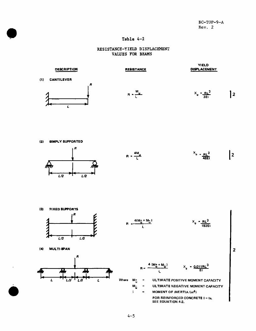
Table 4-2
RESISTANCE-YIELD DISPLACEMENT VALUES FOR BEAMS
BC-TOP-9-A Rev. 2
DESCRIPTION RESISTANCE YIELD
DISPLACEMENT
(1) CANTILEVER
I M.. xe -_Qi! 6 3EI
(2) SIMPLY SUPPORTED
nth
L/2 -H-»
ffni
L/2
4M.. 48EI
(3)
/ / / / / A
FIXED SUPPORTS
L/2
r i i L/2
£ * / / / s
4(M+ + MJJ ) RL J
192EI
(4) MULTI-SPAN
"f-L/2 ' L/2
^
4 (M+ + M- ) u u 0.011RLJ
El
Where M+ u Nl-
ULTIMATE POSITIVE MOMENT CAPACITY
ULTIMATE NEGATIVE MOMENT CAPACITY
MOMENT OF INERTIA (in4)
FOR REINFORCED CONCRETE I = la, SEE EQUATION 4-2.
4-5
BC-T0P-9-A Rev. 2
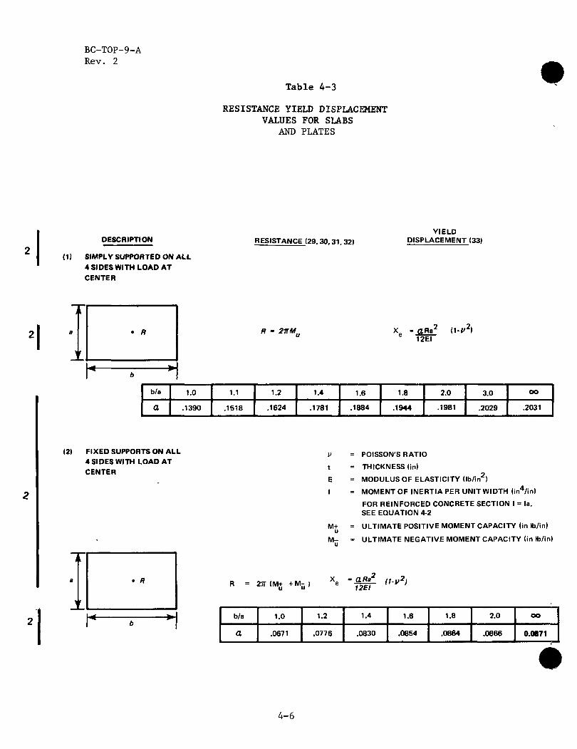
Table 4-3
RESISTANCE YIELD DISPLACEMENT VALUES FOR SLABS
AND PLATES
DESCRIPTION
(1) SIMPLY SUPPORTED ON ALL 4 SIDES WITH LOAD AT CENTER
RESISTANCE (29, 30,31.32) Y IELD
DISPLACEMENT (33)
a • R
!'
«* > b
21TM.. •• gRa 2 ( l - y 2 ) 12EI
b/a
a 1.0
.1390
1.1
.1518
1.2
.1624
1.4
.1781
1.6
.1884
1.8
.1944
2.0
.1981
3.0
.2029
oo
.2031
(2) F IXED SUPPORTS ON ALL 4 SIDES WITH LOAD AT CENTER
R = 27T (M+ + M- |
M+ u M -u
POISSON'S RATIO
THICKNESS (in)
MODULUS OF ELASTICITY ( lb/ in2 )
MOMENT OF INERTIA PER UNIT WIDTH ( in4 / in)
FOR REINFORCED CONCRETE SECTION I = la, SEE EQUATION 4-2
ULTIMATE POSITIVE MOMENT CAPACITY (in lb/in)
ULTIMATE NEGATIVE MOMENT CAPACITY (in lb/in)
Xe -fgf «-»2>
b/a
a
1.0
.0671
1.2
.0776
1.4
.0830
1.6
.0854
1.8
.0864
2.0
.0866
oo
0.0871
4-6
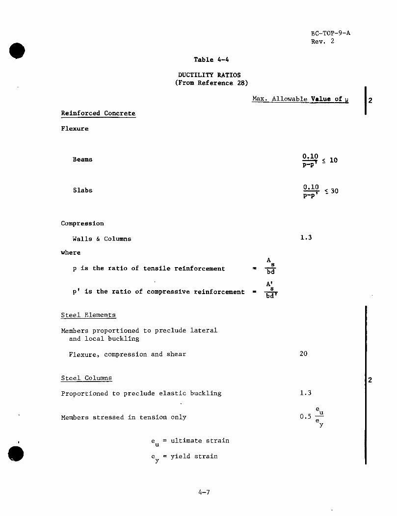
Reinforced Concrete
Flexure
BC-T0P-9-A Rev. 2
Table 4-4
DUCTILITY RATIOS (From Reference 28)
Max. Allowable Value of u
Beams 0.10 P-P'
< 10
Slabs 2 ^ 1 3 0 P-P
Compression
Walls & Columns
where
p is the ratio of tensile reinforcement •
p' is the ratio of compressive reinforcement ™
A s_
bd A» s
"bd7
1.3
Steel Elements
Members proportioned to preclude lateral and local buckling
Flexure, compression and shear 20
Steel Columns
Proportioned to preclude elastic buckling
Members stressed in tension only
e = ultimate strain u
e = yield strain y
1.3
e 0.5 -* e
y
4-7

IS)
o *i o g o B t>
D
1 oo
tn
M
O
i^
H
o z en n o w
*i
*t
H
n H
H W
*1
O
F5
() J<J
w
a H o H z td a
*1
H-
0 hi
CD
*. 1 t-
1
COEF
FICI
ENT
F
7* n < ro Cd
n i H
O
TJ
VO >
p ro
o i ro
3 + CO
•ol-o
II •o
3 + o CO
"o|-o
IO
3
11/
CO
Q.|
Q.
Vi "
o 7s
II I 3 + ? ro
ro
" 7\
+ 3 ro
o- >
Q
-\Z>
II
Q. 3 II
mlm
3D
J>
-I
-»
5 9
n 3 I a. la
.
^ ~r
ro
•c
o o
b ro
O
O
l
j8s?
£- o o
-*
en »
J o
o O
l
[/A
/
o II m
Q.

BC-T0P-9-A Rev. 2
SECTION 5
SPECIAL PROBLEMS
Two special problems are the determination of an empirical formula for force-time history of automobile crash, and the evaluation of a missile's velocity as it passes through a liquid.
5.1 FORCE-TIME HISTORY FOR AUTOMOBILE CRASH
In deriving the force-time history of an automobile crash under frontal impact, the automobile is considered as a deformable missile and the structure as a rigid target. According to Appendix D, Paragraph D.l, which is based on a theoretical consideration and considerable experi-mental data, the force-time history under such a condition is approxi-mately as follows:
F(t) = 0.625 V W sin 20t, (0 < t < 0.0785 sec) 8 m (5-1)
F(t) = 0 (t > 0.0785 sec)
where
t = time from the instant of initial contact (sec)
F(t) * time-dependent force on target (lb)
V » striking velocity of the automobile (ft/sec) s
W - weight of automobile (lb) m
References on derivations of more elaborate force-time histories for auto-mobile crashes are given in reference 11.
5.2 PENETRATION OF A MISSILE THROUGH A LIQUID
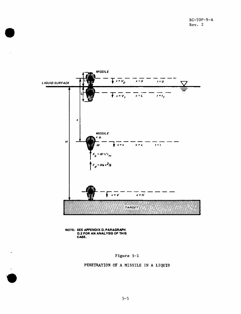
To evaluate the effect of a missile on a target that is submerged in a liquid, determine the striking velocity of the missile, V, after it has penetrated through a depth, H, of liquid covering the target (figure 5-1). This involves evaluating the velocity change due to missile weight, the buoyant force, and the drag force.
The penetration of a missile as it enters a liquid depends on the geometric shape of the missile. For the vertical entry of a missile with uniform horizontal cross-sectional area A., and length L, the depth of penetration and the velocity at a depth, x, are in terms of two functions of x. (The functions are evaluated at x - H or L.)
5-1

BC-T0P-9-A Rev. 2
9 —Jaii ? ?
Z (x) = g/a + bAQ(l-2ax)/2aZ + e aX(VQ -g/a-bAQ/2a
Z), (0 <x<L) (5-1)
r, r N „ 2 -2ax Z2(x) = V2 + e bAQ [e2aL(l-2aL)-l] /2a2 + VQ
2 + g(e2aL Y/Ym-l)/a
(x > L) (5-2)
Notations used above are defined at the end of this section. Missile pene-tration in a liquid can be catagorized by the following cases:
5.2.1 LIQUID DEPTH IS LESS THAN OR EQUAL TO MISSILE LENGTH (H< L)
5.2.1.1 If Z (x) is Negative or Zero at Depth x - H (Z (H) < 0)
The missile will not strike the target. It will penetrate a depth H < H such that Z.. (H ) - 0, and then float to the liquid surface.
5.2.1.2 If Z (x) is Positive at Depth x = H (Z (H) > 0)
The striking velocity at depth H is
V = hx (H)j 1 / 2 (5-3)
5.2.2 LIQUID DEPTH IS GREATER THAN MISSILE LENGTH (H > L)
5.2.2.1 If Z (x) is Negative or Zero at Depth x - L (Z (L) < 0)
The missile will not strike the target. It will penetrate a depth H- < L such that Z1(H ) = 0, and then float to the liquid surface.
5.2.2.2 If Z (x) is Positive at Depth x - L (Z (L) > 0)
The missile will penetrate the liquid deeper than L. There are two possibilities:
A. If Z2(x) is Negative or Zero at Depth x = H (Z2(H) < 0)
The missile will not strike the target. It will penetrate a depth H (L< H < H) such that Z (H ) = 0, and then float b liquid surface.
B. If Z„(x) is Positive at Depth x = H (Z9(H) > 0)
The striking velocity at depth H is
Z2(H)| 1 / 2 (5-4)
5-2
BC-T0P-9-A Rev. 2
In case the missile shape does not have a uniform cross-sectional area, refer to equations (D-23) and (D-36) in Appendix D.2 for more general solutions.
5.2.3 DEFINITIONS OF NOTATIONS
a - YA Q CD/2W (5-5)
b = Yg/W (5-6)
g = gravitational acceleration
(g « 32.17 ft/sec^ at sea level)
W = weight of missile
Y = weight density of liquid
(Y= 62.4 lb/ft3 for water at 80°F)
Ym = weight density of the missile
x • depth of missile e.g. below the initial e.g. as shown in figure 5-1. An « horizontal cross-sectional area of the missile (constant over
Length L) C = drag coefficient (given in table 5-1 or other references on fluid
mechanics) which is a function of L/d, R and shape of the missile.
L - vertical length of the missile
d = characteristic dimension of the missile as shown in table 5-1.
V R - Reynolds number = —-— (5-7)
v m kinematic viscosity„of the liquid ( - 0.95 x 10⁻⁵ ft'/sec for water at 80°F)
V = initial velocity of the missile at x - 0 (See figure 5-1)
V • striking velocity of the missile at x - H (See figure 5-1)
V2 - terminal velocity - g(l - Y/Ym)/a] (5-8)
5-3

BC-T0P-9-A Rev. 2
Table 5-1
DRAG COEFFICIENT FOR VARIOUSLY SHAPED BODIES IN INCOMPRESSIBLE FLOW
Form of Body
Circular disk
Tandem disks, L - spacing d • diameter
Rectangular plate, L • length d = width
Circular cylinder (axis II to flow) L = length d = diameter
Circular cylinder (axis 1 to flow) L = length d = diameter
Streamlined foil (1 : 3 airplane strut) L = span d = chord
Hemisphere: Hollow upstream Hollow downstream
Sphere
Ellipsoid ( 1 : 2 , major axis II to flow)
Airship hull (model)
L/d
0 1 2 3
1 5 20 CO
0 1 2 4 7
1 5 20 OO
5 OO
OO
R
>io3
>103
>103
>103
105
>5 x 10⁵
>4 x 10⁴
>103
105
>3 x 10⁵
>2 x 10⁵
>2 x 10⁵
CD
1.12
1.12 0.93 1.04 1.54
1.16 1.20 1.50 1.95
1.12 0.91 0.85 0.87 0.99
0.63 0.74 0.90 1.20
0.35 0.33
0.07
1.33 0.34
0.5 0.20
0.07
0.05
5-4
BC-T0P-9-A Rev. 2
LIQUID SURFACE
MISSILE
lH^-Vg x~0
1T"'V1
t*=0
x - L t = f ,
V
If " If X » X f = f
«
NOTE: SEE APPENDIX D, PARAGRAPH D.2 FOR AN ANALYSIS OF THIS CASE.
Figure 5-1
PENETRATION OF A MISSILE IN A LIQUID
5-5
•
BC-T0P-9-A Rev. 2
APPENDIX A
CROSS REFERENCE LISTING TO AEC STANDARD SAR FORMAT
This appendix shows the cross reference between sections of AEC's Standard SAR format and the sections of this topical report.
AEC SAR Format BC-TOP-9
3.5.4 2.0, 3.0, 4.0
A-l

BC-T0P-9-A Rev. 2
APPENDIX B
GLOSSARY
B.l PENETRATION
Penetration is the displacement of the missile into the target. It is a measure of the depth of the crater formed at the zone of impact.
B.2 PERFORATION
Perforation is "full Penetration" or where the missile passes through the target with or without exit velocity (of missile).
B.3 SPALLING OF CONCRETE
Spalling is the peeling off of the back face of the target opposite to the face of impact.
B.4 DUCTILITY RATIO
The ductility ratio is the ratio of the maximum deflection to the deflection at the "effective yield point."
B.5 EFFECTIVE YIELD POINT
That point on an idealized bilinear resistance function separating the elastic and perfectly plastic portion of the function. The effective yield point is based on the strength of the structure by ultimate (or plastic) design methods.
B.6 ELASTIC IMPACT
An elastic collision is characterized by elastic deformations at the missile-target interface.
B.7 PLASTIC IMPACT
A plastic collision is characterized by inelastic deformation and local damage of the missile and/or target in the impact zone. For a purely plastic collision, elastic restoring forces at the missile-target inter face and associated elastic rebound energy release converge to zero.
B-l

BC-T0P-9-A Rev. 2
APPENDIX C
REVIEW OF EXISTING FORMULAS
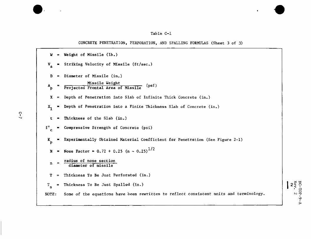
C.l PENETRATION AND PERFORATION
The most common formulas used in determining the local effects of a missile on a target, such as penetration, perforation, and spalling for missiles striking either a concrete or steel target, are given in tables C-1 and C-2. These tables include equations C-1 through C-ll. These are the current state-of-the-art formulas on impact analysis, which consists primarily of empirical methods based on experiments conducted for specific and limited applications. Generally, the experiments were conducted for the Government using missiles, such as bombs and bullets, and having velocities above 1000 ft/sec. Current impact analysis assumes that the missile impinges the target normal to the surface. The effects of the oblique angle of striking at various velocities are illustrated in figure C-1. It can be seen that assuming normal striking of the target is conservative, since a small deviation from a normal impact decreases the depth of penetration considerably.
The Army Corps of Engineers and National Defense Research Committee equations (table C-1) for penetration, perforation, and spalling have a term, which depends only on the diameter of the missile. However, this term provides overly conservative results when a low velocity and large diameter missile is considered. For example: as Vs -»• 0 the penetration approaches 0.5D; perforation approaches (1.8)D; and spalling approaches (2.8)D, which is not realistic.
Experimental data with velocities below 500 ft/sec are just beginning to develop, with the emphasis on the effect of impact on the target. Some experiments have been completed with missile velocities in the range of interest. However, the tests were not necessarily conducted for target information.(21) Therefore, available pertinent data are limited.
The modified Petry formula has had the widest application for determining the penetration of a missile into concrete targets and is adopted for use at the present time. It was developed by the Poncelet theory, provides estimate of penetration, and has functioned best in the velocity range of interest. Also, conservatism is built into this approach because of the following:
A. The angle of striking the target has a large effect if the angle is greater than 20°. A normal angle of strike is assumed.
C-1
BC-T0P-9-A Rev. 2
B. The probability of a missile being oriented in a manner that would produce the greatest penetration is remote. In addition, any rotational effect tends to increase the area of impact.
C. Conservative estimates for weight, velocity, area of impact, and target strength provide conservatism.
Even though the modified Petry formula was developed in 1910, the material coefficient for penetration, Kp, has been revised by experiments and is reported by Amirikian(l^) and shown in figure 2-1.
The BRL formula for perforation of concrete targets is used. It is selected instead of the modified Petry formula of T - 2X because the BRL formula was developed for perforation and not as an approximation from a penetration.
The BRL equation, given in equation (2-3), has been modified to account for concrete strength other than 3000 psi by replacing the constant coefficient concrete strengtn otner tnan JUUU psi 7.8 by 427/\ffjt in equation (C-7).'3)
Two steel perforation formulas are available, the Ballistic Research Laboratories (BRL) formula^) (3) arl(j t^e Stanford Research Institute formula, known as the Stanford Equation.(2°) The Stanford Equation is based on experimental data, using missile velocities within -the range of interest. However, its limits of applicability are very restrictive because most missiles encountered fall outside the range of the Stanford Equation.
The Ballistic Research formula, table C-2, is used with an assigned value of K equal to unity. Rearranging terms and solving directly for T leads to the formula for calculating the threshold of perforation.
(C-12)
The Stanford Equation (table C-2) has the following defined limits of applicability:
0.1 < T/D < 0.8,
0.002 < T/L < 0.05,
10 < L/D < 50,
5 < W/D < 8,
8 < W/T < 100,
C-2

#
BC-T0P-9-A Rev. 2
70 < V < 400, s
L - length of cylindrical missile
V » striking missile velocity normal to the target surface for the threshold of perforation (ft/sec)
Solving equation (C-ll) directly for plate thickness gives,
W V / 2 0.045 -j^-+ 0.0022/£- \ - 0.047 £- (C-13)
where,
2 W V m s
W » weight of missiles (pounds) m
A parametric study comparing the BRL formula and the Stanford Equation, within the limits of applicability of the Stanford Equation, showed the BRL and SRI formula are generally in good agreement for the shorter spans. But, for longer spans the SRI formula is less conservative. Considering this and the narrow band of limits for the SRI equation the BRL equation is used for design.
C.2 MULTIPLE ELEMENT BARRIER EQUATION
Equation (2-9) assumed the residual kinetic energy of the missile after perforation (Er) is the difference between the kinetic energy of the missile before impact (E^) and the energy required to perforate the steel (Ep)
2 2 2 MV MV MV E r " E k - E
P " ^ - r - - r - - ^ <C"14>
where
'lb-M • mass of the missile
2\ sec j
C-3
BC-T0P-9-A Rev. 2
Solving for V
/ 2 2\1/2
r Vs 7 (27)
This equation neglects the mass of the plug which may be punched out of the target, which would be very small for a steel target; for a concrete target, the concrete would fracture and not act in conjunction with the missile mass.
Vp can be obtained from equations (2-3) and (2-7) by solving for Vs, which will be the velocity to just perforate, V , when a given thickness of target, t, is used.
C-4

#
Table C-1
CONCRETE PENETRATION, PERFORATION, AND SPALLING FORMULAS (Sheet 1 of 3)
Identification Formula Remarks Equation
No.
A. Penetration into Reinforced Concrete
o l
Modified Petry (Refs. 13, 14, 15)
X = 1 2 V p 1 O g 1 0 \ 1 + 2-15f000
*1 1 + e (H
For infinitely thick slab
Depth of penetration for slabs with Finite thick-ness. X -> X when t + 3X
C-1
Army Corps of Engineers and National Defense Research Comit tee (Refs. 13 , 16, 17)
X 282 W D 0.215
V * " . DJ \1000 /
1.5 + 0.5D C-2
Aramann & Whitney (Refs. 18, 19).
282 N W D0-2 / ys \ 1 , 8
^ c D2 \ 100° / C-3
B. Concrete Thickness to be Just Perforated
Modified Petry (Refs. 13, 14, 15)
T = 2X X is obtained from Equation (C-1)
C-4
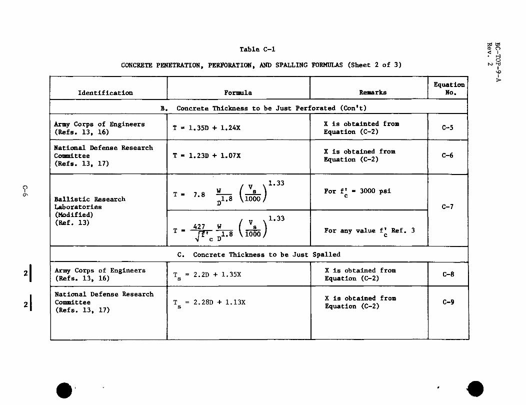
Table C-1 <g 9
CONCRETE PENETRATION, PERFORATION, AND SPALLING FORMULAS (Sheet 2 of 3) ^ f
Identification Formula Remarks Equation
No.
B. Concrete Thickness to be Just Perforated (Con't)
Army Corps of Engineers (Refs. 13, 16)
National Defense Research Committee (Refs. 13, 17)
Ballistic Research Laboratories (Modified) (Ref. 13)
T - 1.35D + 1.24X
T - 1.23D + 1.07X
( Vs ^ ' ^ T ' 7'8 D1.8 VIOOO/
/ v x1-33
_ 427 W ( s i
j^cD 1* 8 V l ° 0 ° /
X is obtainted from Equation (C-2)
X is obtained from Equation (C-2)
For f* - 3000 psi c
For any value f' Ref. 3
C-5
C-6
C-7
C. Concrete Thickness to be Just Spalled
Army Corps of Engineers (Refs. 13, 16)
National Defense Research Committee (Refs. 13, 17)
T = 2.2D + 1.35X s
T = 2.28D + 1.13X s
X is obtained from Equation (C-2)
X is obtained from Equation (C-2)
C-8
C-9
• - #
•
o I
Table C-1
CONCRETE PENETRATION, PERFORATION, AND SPALLING FORMULAS (Sheet 3 of 3)
W =
s
D =
Weight of Missile (lb.)
Striking Velocity of Missile (ft/sec.)
Diameter of Missile (in.)
Missile Weight P
X
h
(psf)
t =
f
K P
N =
n =
T =
s
NOTE:
Projected Frontal Area of Missile
Depth of Penetration into Slab of Infinite Thick Concrete (in.)
Depth of Penetration into a Finite Thickness Slab of Concrete (in.)
Thickness of the Slab (in.)
Compressive Strength of Concrete (psi)
Experimentally Obtained Material Coefficient for Penetration (See Figure 2-1)
Nose Factor = 0.72 + 0.25 (n - 0.25)1/2
radius of nose section diameter of missile
Thickness To Be Just Perforated (in.)
Thickness To Be Just Spalled (in.)
Some of the equations have been rewritten to reflect consistent units and terminology.
pa td
* < i • H
O M i-d
I \o I >

Table C-2
PERFORATION IN STEEL FORMULAS
so n> o < i • H
O i 1 >
Identification Formula Remarks Equation No.
Ballistic Research Lab (Refs. 2, 3, 13)
n3/2 0.5 MV
17,400 K 2 D 3 / 2 C-10
Stanford Research Institute (Ref. 20) D 46,500 (
16,000 T + 1,500^-H See Limits page C-3 C-ll
T = steel thickness to be just perforated (in.)
2 M = mass of the missile (lb-sec /ft),
V = striking velocity of the missile normal to target surface (ft/sec),
K = constant depending on the grade of the steel, (K is usually » 1,)
D = diameter of the missile (in.)
E = critical kinetic energy required for perforation (ft-lb),
S * ultimate tensile strength of the target minus the tensile stress in the steel (psi)
W = length of a square side between rigid supports (in.),
W - length of a standard width (4 in.). (See Ref. 20)

BC-T0P-9-A Rev. 2
Effect of Oblique Strike
W/Perforation
JL i lXJ i^Cf l^ '2533 '2933 '2521
v,=
' I4M 1, <f^J \ y v
1391 I 4 t 0 1492 NIC. 1474 HIC. .
" ' i r f 1 / ' i I Lu—i J^^Sy J I r^iTV^, '972 NIC. TOO WC. W Al
V,= 729 RiC. CS9 RlC.
37 MM. M80 Projectile Concrete Thickness = 22". Compressive strength = 5700 lbs / in. Striking velocity (Vs) and angle of obliquity ( 6 ) shown. Stuck projectiles and path of ricochet projectiles shown.
Figure C-1
TYPICAL CRATER PROFILES
C-9
BC-T0P-9-A Rev. 2
APPENDIX D
DERIVATIONS
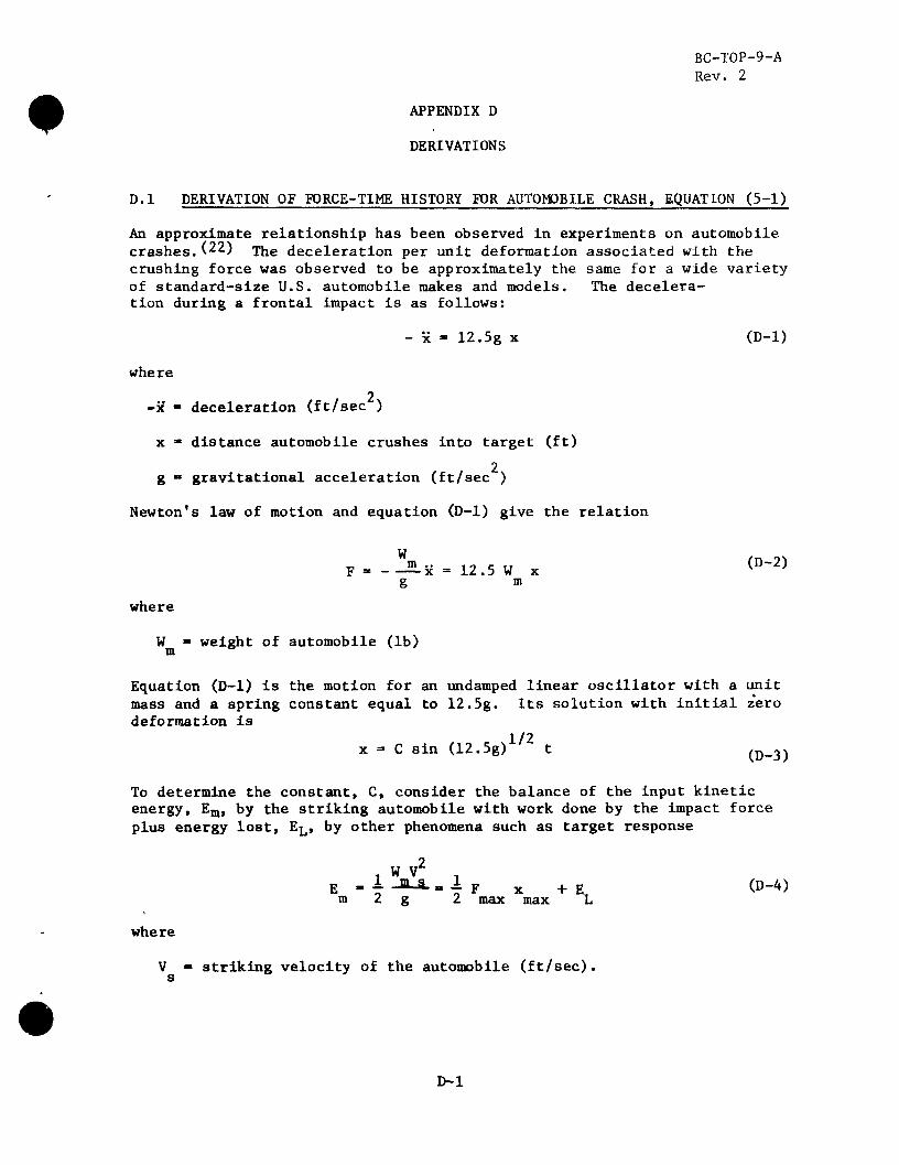
D.l DERIVATION OF FORCE-TIME HISTORY FOR AUTOMOBILE CRASH, EQUATION (5-1)
An approximate relationship has been observed in experiments on automobile crashes.(22) The deceleration per unit deformation associated with the crushing force was observed to be approximately the same for a wide variety of standard-size U.S. automobile makes and models. The decelera-tion during a frontal impact is as follows:
- x = 12.5g x (D-l)
where 2
-x - deceleration (ft/sec )
x * distance automobile crushes into target (ft)
2 g ™ gravitational acceleration (ft/sec )
Newton's law of motion and equation (D-l) give the relation
W _ m .. n c ,T (D-2) p = x = 12.5 W x
g m where
W «• weight of automobile (lb) m
Equation (D-l) is the motion for an undamped linear oscillator with a unit mass and a spring constant equal to 12.5g. Its solution with initial zero deformation is
1/2 x =• C sin (12.5g) t (D_3)
To determine the constant, C, consider the balance of the input kinetic energy, Em, by the striking automobile with work done by the impact force plus energy lost, EL» by other phenomena such as target response
2
E -lXl.iF x +E (D-4) m 2 g 2 max max L
where
V " striking velocity of the automobile (ft/sec). s
D-l

BC-T0P-9-A Rev. 2
In the conservative case of EL " 0 the constant C can be determined by substituting equations (D-2) and (D-3) into equation (D-4)
U2.5gj
1/2
Finally substituting equations (D-3) and (D-5) into equation (D-2) gives the force-time history
F - 12.5 W ( T A - ) V s i n (12.5g)1/2 t m \12.5g/ s (D-6)
- 0.625 V W sin 20 t s m
This is a sine wave of frequency U) • 20 rad/sec and period T • 2TT/U) = 0.314 sec. The maximum force occurs at t • T/4 = 0.0785 sec when the velocity of the striking automobile is zero relative to the rigid surface
I and then rapidly reducing to zero. Thus under the condition of plastic col-lision (i.e., missile and target acquire same velocity after impact) the duration of the impact force is from t = 0 to t = T/4 = 0.0785 sec. At
I t = 0.0785 sec, the force diminishes from a maximum value to zero.
As an example of using the resulting expressions, consider the experimental data in reference 23. Test No. 505-IW for a 1963 Plymouth automobile striking a rigid wall yielded the following data.
W - 3270 lb m V « 53.3 mph = 78.17 ft/sec
x - 3.82 ft max
gF /W = 25g 6 ave m B
(average over distance)
From equations (D-3) and (D-5) arid the above data the stopping distance is
vl/2 x max
•(izhs) (78.17) = 3.91 ft
According to the forcing function equation (D-6) the average deceleration (average over distance, not over time) for Test No. 505-IW i»
gF /W - gF /2W - (0.625)(78.17)g/2 - 24.42g ° ave m ° max m ° °
which agrees with the test result (25g) quite closely.
D-2
BC-T0P-9-A Rev. 2
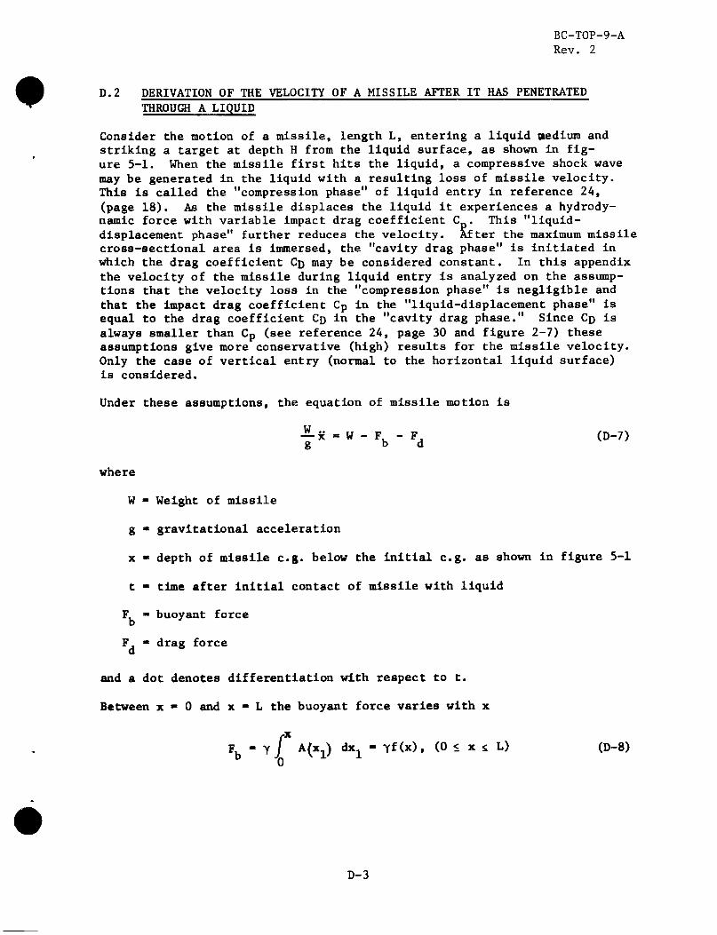
D.2 DERIVATION OF THE VELOCITY OF A MISSILE AFTER IT HAS PENETRATED THROUGH A LIQUID
Consider the motion of a missile, length L, entering a liquid medium and striking a target at depth H from the liquid surface, as shown in fig-ure 5-1. When the missile first hits the liquid, a compressive shock wave may be generated in the liquid with a resulting loss of missile velocity. This is called the "compression phase" of liquid entry in reference 24, (page 18). As the missile displaces the liquid it experiences a hydrody-namic force with variable impact drag coefficient C . This "liquid-displacement phase" further reduces the velocity. After the maximum missile cross-sectional area is immersed, the "cavity drag phase" is initiated in which the drag coefficient Cn may be considered constant. In this appendix the velocity of the missile during liquid entry is analyzed on the assump-tions that the velocity loss in the "compression phase" is negligible and that the impact drag coefficient Cp in the "liquid-displacement phase" is equal to the drag coefficient CD in the "cavity drag phase." Since Co is always smaller than Cp (see reference 24, page 30 and figure 2-7) these assumptions give more conservative (high) results for the missile velocity. Only the case of vertical entry (normal to the horizontal liquid surface) is considered.
Under these assumptions, the equation of missile motion is
— x - W - F, - Fj (D-7)
g b d
where
W - Weight of missile
g - gravitational acceleration
x - depth of missile e.g. below the initial e.g. as shown in figure 5-1
t - time after initial contact of missile with liquid
F « buoyant force F, - drag force d
and a dot denotes differentiation with respect to t.
Between x - 0 and x - L the buoyant force varies with x
rx
Fb - Yj A(X;L) dx± - Yf(x), (0 < x s L) (D-8)
D-3

BC-T0P-9-A Rev. 2
where
Y • weight density of the liquid
K"i) horizontal cross-sectional area of the missile at vertical distance x. from the tip
When x > L the buoyant force is a constant
Fb - WY/Ym, (x > L) (D_9)
where
Y • weight density of missile m
The drag force is given by the expression
Fd - V Am CD v 2 / 2* (D-10)
where
A • maximum horizontal cross-sectional area of missile m
v • x « velocity of missile at depth x
If the liquid is assumed to be incompressible, the drag coefficient, Cj), in equation (D-10) is a function of the missile shape and the Reynolds number R, defined as
V R - — (D-ll)
where
d » characteristic dimension of missile as shown in table 5-1
V_ • initial velocity (at t»0 and x»0) of missile
v • kinematic viscosity of liquid
Table 5-1 from reference 25 lists some typical values of Cj) for variously shaped bodies in incompressible fluid flow. Reference 24 (page 35) presents some CD values for a family of nose shapes. Other references on fluid mechanics can also be consulted.
•
D-4

BC-T0P-9-A Rev. 2
Substituting equations (D-8), (D-9) and (D-10) into equation (D-7) results in the following two forms of the equation of motion and solutions:
A. For 0 < x < L
x + ax2 + bf(x) - g = 0 , (0 < x < L) (D-12)
where
a = YA C„/2W (D-13)
m D
b = Yg/W (D-14)
and f(x) is given in equation (D-8). This is a nonlinear, second order, nonhomogeneous, ordinary differ-ential equation for x(t). According to reference 26 (page 551) it can be solved as follows:
Let
2 2 y(x) = x * v (D-15)
Then if a prime denotes differentiation with respect to x,
y*(x) - 2x(x)' <= 2x x/x = 2 x (D-16)
Equation (D-12) becomes
y'(x) + 2ay(x) = 2g - 2bf(x) (D-17)
which is a linear, first order, nonhomogeneous, ordinary differen-tial equation for y(x), and has the solution
y(x) - J2 ju(x) [g-bf(x)] dx + c}/u(x) (D-18)
where c is the integration constant and
J2adx „, . m a . 2ax (D-19) M(x) • e = e
D-5
BC-T0P-9-A Rev. 2
Substituting equation (D-19) into equation (D-18) gives
y(x) - v2-e"2aX f2g fe2ax dx - 2b | e 2 a x f(x) dx + c]
g/a - 2be ** G(x) + c e , (0 < x < L) (D-20)
where
(x) - fe f (x) dx - J dx «• / e 2 ax r A(XI) dX] dx (D-21)
in which equation (D-8) has been used.
At the initial position (See figure 5-1) x - 0, v - V., and equation (D-20) gives
c - VQ - g/a + 2bG(0)
Then equation (D-20) becomes
y(x) = v2 « g/a + e"2ax JVQ2 - g/<
+ 2b [G(0) - G(x)]| , (0 < x < L)
At x = L equation (D-21) gives
G(L) /e 2" \f A(xl} dx, dx x-L
and equation (D-23) g ives
y(L) - V,2 - V22 + gY/Yma + e"2aL jvQ
2 - g/i
+ 2b [G(0) - G(L)]}
(D-22)
(D-23)
(D-24)
(D-25)
D-6

BC-T0P-9-A Rev. 2
where V.. is the missile velocity at x - L (See figure 5-»l) and
^-f^-^m) (D-26)
Consider the special case of a missile with uniform horizontal cross-sectional area A . Then A(x. ) - A . Equation (D-21) gives
G(x) - y"e2ax If* A0dXl) dx - A 0 / xe2axdx
2ax 2 A ^ (2ax-l)/4a , (0 < x < L)
(D-27)
from which
G(0) - -AQ/4a2 (D-28)
and
2«T 2 G(L) - A0e
<cai' (2aL-l)/4a* (D-29)
Equation (D-23) becomes
v2 - g/a + bAp (1 - 2ax)/2a2 + e"2ax (V Q2 - g/a
2 X (D-30) - bAQ/2a
2 ) , (0 < x < L)
Formulas for other missile shapes can be derived similarly.
For x > L
3c + ax2 + gY/Yn - g - 0 , (x > L) (D-31)
This is a special case of equation (D-12) with
f (x) - gY/Ymb , (x > L) (D-32)
which, when substituted into equation (D-20), gives
v2 - V22 + ke"2ax , (x > L) (D-33)
D-7

BC-T0P-9-A Rev. 2
The integration constant k can be determined by the condition that at x • L, v • V, obtained in equation (D-25)
- (V - V) (D-34)
Hence the missile velocity at x > L is given by
L) (D-35)
Substituting V, from equation (D-25) into equation (D-35) gives
„ 2 -2ax V2 + e [2b (G(0) - G(L)) + VQ
4
g(e 2 a LY /Y m - l ) /a ]
1/2 (D-36)
, (x > L)
In the special case of a missile with uniform horizontal cross-sectional area An equations (D-28) and (D-29) are substituted into equation (D-36) to give
„ 2 -2ax V_ + e [bAQ (e
2aL (1 - 2aL) - 1) /2£
+ VQ2 + g ( e 2 a L Y/Ym~l)/a]
1/2 (D-37)
, (x > L)
At x - H, when the missile strikes the target (See figure 5-1) the velocity V is given by equation (D-36) or equation (D-37) with x replaced by H.
D-8

BC-T0P-9-A Rev. 2
APPENDIX E
SAMPLE APPLICATIONS
E.l CONCRETE (PENETRATION, PERFORATION AND SPALLING)
A 4-inch x 12-inch wooden plank, weighing 108 pounds, strikes at 300 mph (440 fps) in a normal head-on collision with a reinforced concrete (f'c - 3000 psi) wall. The plank has a 48 square inch cross-sectional area with the equivalent diameter of 7.8 inches.
E.l.l PENETRATION
Penetration is given by equation (2-1):
X - 12 KpApL°Sio I1 + 215000
For 3000 psi concrete K - 0.00348 (figure 2-1)
and
\ = WI44 = 324 psf
Then
/ 4402 \ X - 12 x 0.00348 x 324 x Log10 ( 1 + ^ Q Q Q 1 - 3.77 in.
When the thickness of a wall is less than 3 x 3.77 = 11.3 in., the depth of penetration is given by equation (2-2):
1 + e < - *)
For example, for a wall with thickness t = 8 in., we get:
; + A * » -2)' x 3.77 - 6.08 in.
E-l
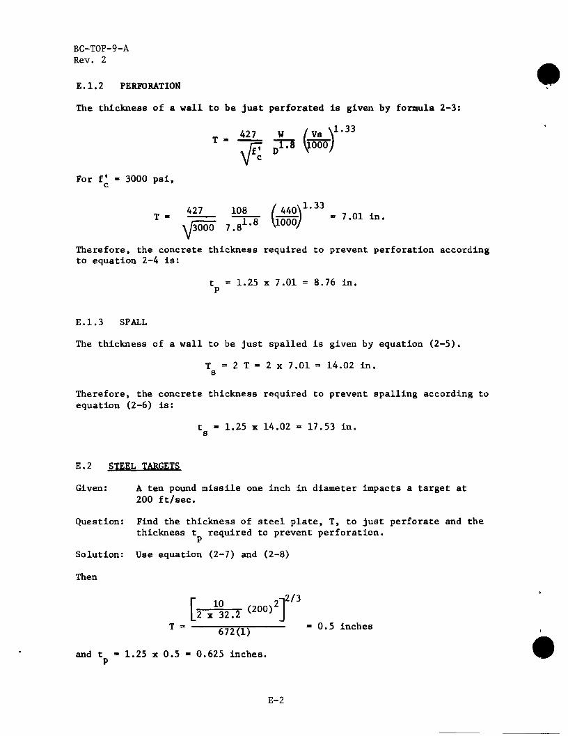
BC-T0P-9-A Rev. 2
E.1.2 PERFORATION
The thickness of a wall to be just perforated is given by formula 2-3:
k1.33 ' / vs j"T5 li nnn
V c
For f - 3000 psi, c
T - 4 2 7 W /Vs \
rp ^ 5 \joooj
427 108 / 440\1,33 , „ . « 7.01 in. •y/3000
108 / 440\ ? g1.8 \l000/
Therefore, the concrete thickness required to prevent perforation according to equation 2-4 is:
t - 1.25 x 7.01 = 8.76 in. P
E.1.3 SPALL
The thickness of a wall to be just spalled is given by equation (2-5).
T - 2 T - 2 x 7.01 = 14.02 in. s
Therefore, the concrete thickness required to prevent spalling according to equation (2-6) is:
t - 1.25 x 14.02 - 17.53 in. s
E.2 STEEL TARGETS
Given: A ten pound missile one inch in diameter impacts a target at 200 ft/sec.
Question: Find the thickness of steel plate, T, to just perforate and the thickness t required to prevent perforation.
Solution: Use equation (2-7) and (2-8)
Then
i2/3
[n?ki <*»>2] T 672(1) * °-5 inche8
and t - 1.25 x 0.5 - 0.625 inches. P
E-2

BC-T0P-9-A Rev. 2
E.3 STRUCTURAL RESPONSE
Consider a 10 lb solid metal missile of 1-inch diameter striking with 200 ft/sec velocity at the mid-span of a simply-supported steel I-beam of 10 ft span and AISC designation W6xl2(8) with static yield strength fy - 50,000 psi. It is required to evaluate the structural response of the beam according to Section 3 under the condition of plastic impact.
According to equation (3-17) the effective mass of the steel beam may be conservatively estimated as the mass of a 13-inch length of the beam (since the depth of beam d - 6" and Dx - 1", the missile diameter) which is for W6xl2 beam(8),
M - 02K13J . 13/ e 12g
According to equation (3-8) for plastic impact, the required target strain energy to absorb the impact energy is
2
M 2 v 2 no\ (200 x 1 2 ) 2 Eg " oA,1" , ' u ^ " N S / / m T7T 32 ,440 i n . - l b f ^ l 2(f+f)
The resistance-displacement function of a simply-supported beam under central loading can be idealized as a bilinear function (figure 3-1 and table 4-2) with
R „ ^S. - *2!*X - 8(21 7) (50,000) (1.2) _ m L Ld (10 x 12) (6) A«»,«K>/ ±D
and
x - ! • ! - (">*"> ^ ° x 1 2> 3 - 0.80 in. e 4 8 E I 48 (30 x 106)(21.7)
where the value of the moment of inertia, I, for the beam cross-section is taken from reference 8, and modulus of elasticity E • 30 x 10" and dynamic increase factor DIF - 1.2 (table 4-1) have been used.
According to figure 3-1 the maximum strain energy for purely elastic structural response is
E - -r R x - i (14,467) (0.80) - 5,787 in.-lb e 2 m e L
E-3

BC-T0P-9-A Rev. 2
which is less than E 8 - 32,440 in.-lb, so the structural response is elasto-plastic. Then according to equation (3-22) the required ductility ratio is
E
\ - if+ \ - <o.80)au6-7)+ ° - 5 -3-30
e m
Since, according to table 4-4 the allowable ductility ratio for a steel beam under lateral loads is 20, this beam can withstand the postulated missile Impact if no other loads are acting simultaneously. In case other loads are present as missile impacts and remain in effect throughout the structural response the required ductility ratio should be evaluated by equation (3-24) instead of equation (3-22).
E.4 MISSILE PENETRATION THROUGH WATER
Consider the postulated accident condition of a fuel shipping cask (the missile) falling from an overhead crane and possibly damaging the spent fuel pool floor slab (the target) underneath. The cask is a cylinder with length L - 17 ft, diameter d - 7 ft, and weight W - 2 x 10⁵ lb. [The spent fuel pool contains water of depth H - 37 ft. If the cask is to drop h - 11 ft to just hit the water surface the initial velocity is
VQ = (2 g h )1 / 2 - [2(32.17) (ll)]172 - 26.6 ft/sec.
The Reynolds number is, according to equation (5-7),
R , V.(26.6) (7) 2. 0 x l 07. V 0.93 x 10 *
Since L/d - 17/7 - 2.43 the drag coefficient is, according to table 5-1 for the case of circular cylinder with axis parallel to flow and with R >. 10^,
CD - 0.854
The horizontal cross - sec t iona l area i s
AQ - ird2/r - TT(7)2/4 - 38.5 f t 2 .
Then equation (5-5) gives
a - ^ - (62 .4 ) (0 .854) (38 .5 ) _ n > 0 0 5 1 f f c - l % ZW 2 (2 x 10⁵)
E-4

#
BC-T0P-9-A Rev. 2
and equation (5-6) gives
b = Yg . (62.4)(32 17) = Q Q1Q ft~l ^ W 2 x 1 0
The weight density of the cask is
*m = ^ L = (38^(17) = 305'6 l b / f t 3'
/2
According to equation (5-8) the terminal velocity is
v2 • [* i1 - ^\ya~i2
= | (32.17) (1 - 62 .4 /305.6) /0 .005l |
Since H > L, and according to equation (5-2)
^ | fe2 a L (1 - 2aL> -l] 2az L J
= 70.9 f t / sec
Z2(L) - V22 + e" 2 a L
+ V + i ( e 2 a L Y/Ym -1)
( 7 0 . 9 ) 2 + e - 2 ( 0 ' 0 0 5 1 ) ( 1 7 > <°-"><38 ;3) [ e ° - 1 7 3 4 (1 - 0.1734) 2(0.005$
- X ] + (26'6)2 + 0 6 l P (e°-173462.4/305.6 - l)j
5027 + (0.8408) [- 4193] - 1502 > 0,
E-5
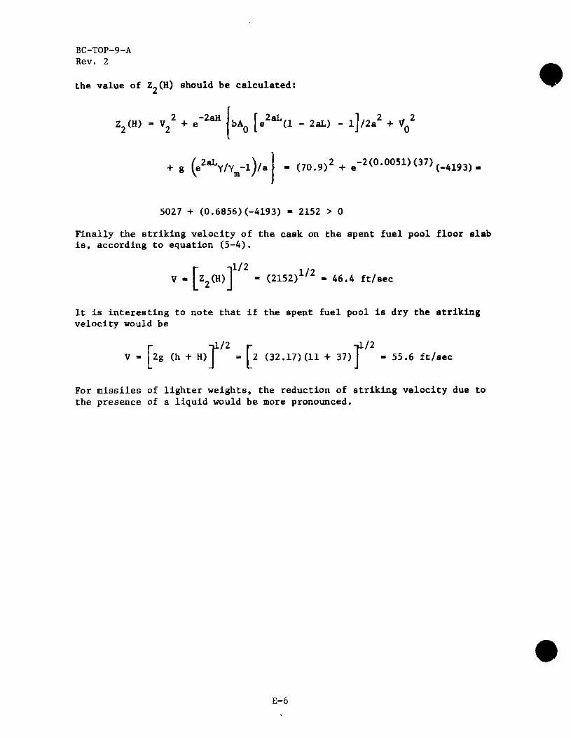
BC-T0P-9-A Rev. 2
the value of Z_(H) should be calculated:
V H ) - V22 + e"
2aH bAQ [e2aL(l - 2aL) - l]/2a2 + V(
2 0
g (e2aLY/Ym-l)/< (70.9)2+e-
2(°-0051)<37)(-4193)
5027 + (0.6856)(-4193) - 2152 > 0
Finally the striking velocity of the cask on the spent fuel pool floor slab is, according to equation (5-4).
V - [z2(H)l 1/2 ,
- (2152)x/^ - 46.4 ft/sec
It is interesting to note that if the spent fuel pool is dry the striking velocity would be
r ~i1/2 r t / 2
V - 2g (h + H) - I 2 (32.17)(11 +37) - 55.6 ft/sec
For missiles of lighter weights, the reduction of striking velocity due to the presence of a liquid would be more pronounced.
#
E-6

BC-T0P-9-A Rev. 2
APPENDIX F
REFERENCES AND BIBLIOGRAPHY
F.l REFERENCES
1. Rotz, J. V., Yeh, G. C. K., Bertwell, W., Tornado and Extreme Wind Design Criteria for Nuclear Power Plants, Topical Report, BC-TOP-3, Revision 3, Bechtel Power Corporation, August 1974.
2. Russell, C. R., Reactor Safeguards, MacMillan, New York, 1962.
3. Fundamentals of Protective Design, TM 5-855-1, Headquarters, Department of the Army, Washington, D.C., July 1965.
4. Norris, C. H., et al., Structural Design for Dynamic Loads, McGraw-Hill Book Company, Inc., New York, New York, 1959.
» 5. Goldsmith, W., Impact, Edward Arnold, Ltd., London, 1960.
6. John M. Biggs, Introduction to Structural Dynamics, McGraw-Hill 1964, pp. 202-244.
7. Newmark, N. M., and Richart, F. E., Impact Tests of Reinforced Concrete Beams, NDRC Report No. A-125, A-213, and A-304, 1941-1946.
8. A.I.S.C. Steel Construction Manual, 7th Edition, American Institute of Steel Construction, N. Y., N. Y., 1970.
9. Building Code Requirements for Reinforced Concrete? ACI Standard 318-71, American Concrete Institute, Detroit, Michigan, 1971.
10. N. H. Burns, C. P. Siess, Plastic Hinging in Reinforced Concrete, ASCE Proc. V92 (J. Struct. Div.) n ST 5 Oct. 1966.
11. Vail, C. F., "Dynamic Modeling of Automobile Structures from Test Data," System Identification of Vibrating Structures - Mathematical Models from Test Data, The American Society of Mechanical Engineers, N. Y. (1972) pp. 149-177.
12. Harris, C. ,M., and Crede, C. E., Shock and Vibration Handbook, McGraw-Hill Book Company, N. Y., 1961.
13. Gwaltney, R. C , Missile Generation and Protection in Light-Water-Cooled Power Reactor Plants, ORNL NSIC-22, Oak Ridge National ' Laboratory, Oak Ridge, Tennessee, for the U. S. Atomic Energy Commission, September 1968.
14. A. Amirikian, Design of Protective Structures, Report NP-3726, Bureau of Yards and Docks, Department of the Navy, August 1950.
F-l
BC-T0P-9-A Rev. 2
15. Samuely, F. J., and Hamann, C. W., Civil Protection. The Architectural Press, London, 1939.
16. Fundamentals of Protective Design, Report ATI207821, Army Corps of Engineers, Office of the Chief of Engineers, 1946.
17. National Defense Research Committee, Effects of Impact and Explosion, Summary Technical Report of Division 2, Volume 1, Washington, D.C.
18. Industrial Engineering Study to Establish Safety Design Criteria for Use in Engineering of Explosive Facilities and Operations Wall Response, a Report Submitted to Process Engineering Branch, A.P.M.E.D. Picatinny Arsenal, Dover, N. J., April 1963.
19. Structures to Resist the Effects of Accidental Explosions, TM 5-1300, Department of the Army, Washington, D.C, July 1965.
20. White, R. W., and Botsford, N. B., Containment of Fragments from a Runaway Reactor, Report SRIA-113, Stanford Research Institute, September 15, 1963.
21. Hardrock Silo Debris Impact Program, Phase I Testing, Test Report, Physics International Co./Bechtel Corp., (unpublished).
22. Emori, R. I., Analytical Approach to Automobile Collisions. Paper No. 680016, Automotive Engineering Congress, Detroit, Michigan (1968).
23. Ivey, D. L., Ruth, E., and Hirsch, T. J., Feasibility of Lightweight Cellular Concrete for Vehicle Crash Cushions. Paper presented at the Annual Meeting of the Highway Research Board, Washington, D.C. (1970).
24. Kornhauser, M., Structural Effects of Impact, Spartan, Baltimore, Maryland, 1960.
25. Rouse, H., and Howe, J. W., Basic Mechanics of Fluids, John Wiley and Son Inc., New York (1953).
26. Kamke, E., Differentialgleichungen L'o'sungsmethoden und L'dsungen, Vol. I. Gewbhnliche Differentialgleichungen (1942), Akademische Verlagsgesellshaft, Becker & Erler Kom.-Ges., Leipzig.
27. Recht, R. F., and Ipson, T. W., Ballistic Perforation Dynamics, J. of Appl. Mechanics, ASME, Sept. 1963.
28. Newmark, N. M., and Haltiwanger, J. D., Air Force Design Manual, AFSWC-TDR-62-138, prepared by the University of Illinois for Air Force Special Weapons Center, Kirtland Air Force Base, N. M., 1962.
F-2
BC-T0P-9-A Rev. 2
Johansen, K. W., Yield-Line Formulae For Slabs, Cement & Concrete Association, London (Translation by Paulin M. Katborg).
Ferguson, P. M., Reinforced Concrete Fundamentals, 3rd Edition, John Witey 1973.
Hognestad, E., Yield-Line Theory For the Ultimate Flexural Strength of Reinforced Concrete Slabs, ACF Journal 24 No. 7 March 1953.
Wood, R. H. Plastic and Elastic Design of Slabs and Plates, Ronald Press Co., 1961.
Timoshenko, S. and Woinowsky-Kriegers, S., Theory of Plates and Shells, Mc-Graw-Hill, 1959.
Cowell, W. L., Dynamic Tests of Concrete Reinforcing Steels, Technical Report R394, U.S. Naval Civil Engineering Laboratory, 1965.
Watstein, D., Effect of Straining Rate on the Compressive Strength and Elastic Properties of Concrete, Journal of the American Concrete Institute, Vol. 24, No. 8, 1953.
McHenry, D., Shideler, J. J., Review of Data on Effect of Speed in Mechanical Testing of Concrete, Bulletin D9, Portland Cement Associ-ation Research and Development Laboratories, (also reprint, Special Technical Publication No. 185, by ASTM, 1956).
Rao, N. R. N., Lohrmann, M., Tall, L., Effect of Strain Rate On The Yield Stress Of Structural Steels, Fritz Laboratory Reprint No. 293, Lehigh University Institute of Research, (also Journal of Materials, Vol. 1, No. 1, American Society for Testing and Materials, March 1966).
Gaston, J. R., Siess, C. P., and Newmark, N. M., An Investigation of the Load-Deformation Characteristics of Reinforced Concrete Beams Up to the Point of Failure, University of Illinois, December 1952, Reprint July 1959.
Denton, D. R., A Dynamic Ultimate Strength Study of Simply Supported Two-Way Reinforced Concrete Slabs, TR 1-789, U.S. Army Engineers Waterways Experiment Station, Corps of Engineers, Vicksburg, Mississippi, July 1967.
Albritton, G. E., Response of Deep Reinforced and Unreinforced Con-crete Slabs to Static and Dynamic Loading, ASCE National Meeting on Structural Engineering, September 30 - October 04, 1968.
Untrauer, R. E., Behavior and Design of Deep Structural Members, Part 4, Dynamic Tests of Reinforced Concrete Deep Beams, University of Illinois, May 1960.
Corley, W. G., Rotational Capacity of R/C Beams, ASCE Proceedings, Journal of Structural Division, October 1966.
F-3

BC-T0P-9-A Rev. 2
43. Feldman, A., Siess, C. P., Investigation of Resistance and Behavior of Reinforced Concrete Beams Subjected to Dynamic Loading, University of Illinois, September 1956.
44. Chelapati, Kennedy E. Wall Probabilistic Assessment of Aircraft Hazard for Nuclear Power Plants, First International Conference on Structural Mechanics in Reactor Technology Berlin 20-24 September 1971.
F-4

BC-T0P-9-A Rev. 2
F.2 BIBLIOGRAPHY
1. A.I.S.C. Plastic Design in Steel, American Institute of Steel Construction, N.Y., N.Y., 1959.
2. Beedle, Lynn S., Plastic Design of Steel Frames, John Wiley & Sons, Inc., 1958.
3. Commentary of Plastic Design in Steel, A.S.C.E. Manual of Engineering Practice, No. 41, 1961.
4. Design for Pipe Break Effects, BN-T0P-2, Bechtel Corp., August 1972.
5. Design of Structures to Resist the Effects of Atomic Weapons, The, EM 1110-345-414 to 421, Massachusetts Institute of Technology for the Office of Chief of Engineers, U.S. Army, Washington, D.C, 1957.
6. Horger, 0. J., Metals Engineering Design. American Society of Mechan-ical Engineers Handbook, McGraw-Hill, New York, 1953.
7. Johansen, K. W., "Pladeformler Formelsamling", Polyteknish Forening, Copenhagen, 2nd Edition, 1954.
8. Johansen, K. W., "Pladeformler", Polyteknish Forening, Copenhagen, 2nd Edition, 1949.
9. Lorenz, Hanz, Gilbert Associates, Inc., Aircraft Impact Design, Power Engineering, Nov. 1970.
10. Newmark, N. M., et al. Notes on Blast Resistant Design, Bechtel Associates Symposium, New York, 1968 (unpublished).
11. Rinder, R., Saffian, L. W., Wachtell, S., Cohen, E., Dobbs, N., Manual for Design of Protective Structures Used in Exposive Proc-essing and Storage Facilities TR3808, Picatinny Arsenal, Dover, New Jersey/Amman and Whitney, New York, New York, November 1968.
12. Wilkins, M. L., Calculation of Elastic-Plastic Flow, UCRL-7322, Lawrence Radiation Laboratory, Livermore, California, January 24, 1969, Rev 1.
F-5