design of speaker cabinets to give optimum...
TRANSCRIPT

1
UNIVERSITY OF NAIROBI
SCHOOL OF ENGINEERING
DEPARTMENT OF ELECTRICAL AND INFORMATION
ENGINEERING
FINAL YEAR PROJECT REPORT
IRUNGU K ELIAS
F17/1376/2010
PROJECT NUMBER: PRJ 097
DESIGN OF SPEAKER CABINETS TO GIVE OPTIMUM [BEST]
RESPONSE FOR, 100W, 250W WOOFERS.

2
IRUNGU K ELIAS
REGISTRATION NUMBER: F17/1376/2010
SUPERVISOR: MR. S.L. OGABA
EXAMINER: DR G.S.O ODHIAMBO
SUBMITTED ON 24th
of April 2015
This project report was submitted as a partial fulfillment of the requirement for
the award of Bachelor of Science degree in Electrical and Information
Engineering from University of Nairobi.
DECLARATION AND CERTIFICATION
This is my original work and has not been presented for a degree award in this or any other
University.
………………………………………..
IRUNGU K ELIAS
F17/1376/2010
3
This report has been submitted to the Department of Electrical and Information Engineering,
The University of Nairobi with my approval as supervisor:
………………………………
MR. S.L. OGABA
Date: ……………………
DEDICATION
I wish to dedicate this project to my family and my supervisor for their support
during the duration of my project, and the endearing knowledge that they have
passed on to me.
You have been a blessing and inspiration to the completion of my studies.

4
ACKNOWLEDGEMENTS
First and foremost, I would like to thank God for giving me the strength and ability to carry out
this project.
I would also like to thank my supervisor, Mr. S.L. Ogaba, for being a source of guidance
throughout the duration of the project.
My appreciation goes out to my classmates for their suggestions and opinions on the project.
Lastly, I would like to appreciate my family for their continuous support.

5

6
TABLE OF CONTENTS
DECLARATION AND CERTIFICATION ................................................................................. 2
ACKNOWLEDGEMENTS .......................................................................................................... 4
TABLE OF CONTENTS ............................................................................................................... 6
ABSTRACT..................................................................................................................................6
CHAPTER 1……………………………………………………………………………………………………………………….7
1. INTRODUCTION
...................................................................................................................8
CHAPTER 2
2.LITERATURE REVIEW..........................................................................................................9
2.1 Sound wave characteristic properties…………………………………………………………………………9
2.2 Frequency and Amplitude…………………………………………………………………………………………10
2.3 Working Principles of a speaker………………………………………………………………………………..11
2.4 Loudspeakers………………………………………………………………………………………………………….11
2.5 Woofer…………………………………………………………………………………………………………………..12
2.6 Understanding woofer Data………………………………………………………………………………….12
2.7 Thiele-Parameters………………………………………………………………………………………………..12
CHAPTER 3
3. DESIGN…………………………………………………………………………………………………………..17 3.1 Woofer Enclosure models…………………………………………………………………………………….17 3.2 Woofer Enclosure Design Procedure…………………………………………………………………….20 3.3 Designing The Box………............................................................................................20
CHAPTER 4
4. Tests on woofers to come up with Frequency Responses…………………………………24 4.1 Open box test………………………………………………………………………………………………………..25 4.2 Frequency test on very large and very small cabinets……………………………………………27

7
CHAPTER 5
5. Cabinet design using the bass box pro software………………………………………30 5.1 Introduction…………………………………………………………………………………………………30 5.2 Procedure……………………………………………………………………………………………………32 5.3 Data analysis………………………………………………………………………………………………..33 5.4 Conclusion And Recommendations…………………………………………………………….34
ABSTRACT
Most public service vehicles and even personal cars have music systems installed with woofer
but most of them produce very poor sound quality. This is because you may find woofer
enclosures poorly designed, hence causing poor frequency response which implies poor sound
response.
What makes a good loudspeaker? My definition of good Hi-Fi loudspeaker
performance is a speaker system that can accurately reproduce the musical
information it is fed. If it is fed a low quality, distorted, compressed recording, it should
produce a low fidelity, distorted and compressed sound. If fed a high fidelity signal with
wide dynamic range and frequency response, that is the sound that should come out of
the speaker system.
Sound is produced from the front and the rear of a speaker‟s cone. These sound waves
must be separated to achieve usable output. If not separated, the output from the front
and rear of the cone would cancel each other out. This is further accentuated with lower
frequencies, and the main reason for mounting a speaker on an enclosure. The enclosure
also absorbs vibration created by the speaker. If not mounted to an enclosure and
simply placed on a solid surface, the vibration created from the speaker‟s movement
may be louder than the sound it emits. An enclosure that does not resonate with the
speaker must be made from a solid and thick material.
Shaping the low-end (bass frequencies below 300Hz) is the reason for choosing a
particular enclosure type. A speaker‟s cone response dictates the signature shape or
sound of the enclosure beyond 200-300Hz . Any speaker will produce sound in any
cabinet, but optimizing the relationship between the speaker and the enclosure is the
key to good bass.

8
Designers must prioritize what performance or sonic characteristics they desire from a product
and determine what aspects of the speaker and cabinet will make it a reality. Output level (or
SPL), power handling, frequency range, and size and weight are all considerations
When one is improved, other factors may suffer. The most difficult part is finding a middle
ground. We want to have it all, but unfortunately, it’s not always so simple.
Woofer enclosure (cabinet) design comes in handy to facilitate production of quality bass with
a flat frequency response from the woofer drivers.
A well designed cabinet is paramount for best entertainment by the users.
CHAPTER 1
1. INTRODUCTION
At ordinary sound pressure levels (SPL), most humans can hear down to about 20 Hz and
up to 20 KHz. Woofers are chosen to handle low frequency sounds typically from around
40 hertz up to about a kilohertz or higher. A woofer enclosure is incorporated to facilitate
the mounting of woofer drivers and any associated electronic hardware, such as
amplifiers and crossover circuits. The primary role of the enclosure being to
prevent sound waves generated by the rearward-facing surface of the diaphragm
of an open driver interacting with the sound waves generated at the front of the
driver.
There are two major types of woofer enclosures:
1. Sealed enclosure
2. Ported enclosure.
Each type of enclosure is chosen depending on the specifications of woofer drivers.
Cabinets are a very important part of the woofer systems as they are used to
facilitated optimum sound response of the driver at the same time housing the woofer
drivers.
In order to understand this, there is thus the need to start from the basics and
understand sound as a wave and how its frequency affects its energy which corresponds to its
amplitude and how to correlate this concept with the working principle of the woofer.

9
CHAPTER 2
2 LITERATURE REVIEW
2.1 Sound
Sound is a vibration that propagates as a mechanical wave of pressure and displacement,
through some medium (such as air or water). Sometimes sound refers to only those vibrations
with frequencies that are within the range of hearing for humans or for a particular animal.
Propagation of sound
Sound propagates through compressible media such as air, water and solids as longitudinal
waves and also as a transverse waves in solids. The sound waves are generated by a sound
source, such as the vibrating diaphragm of a stereo speaker. The sound source creates
vibrations in the surrounding medium. As the source continues to vibrate the medium, the
vibrations propagate away from the source at the speed of sound, thus forming the sound
wave. At a fixed distance from the source, the pressure, velocity, and displacement of the
medium vary in time. At an instant in time, the pressure, velocity, and displacement vary in
space. Note that the particles of the medium do not travel with the sound wave.
This is intuitively obvious for a solid, and the same is true for liquids and gases (that is, the
vibrations of particles in the gas or liquid transport the vibrations, while the average position
of the particles over time does not change). During propagation, waves can be reflected,
refracted, or attenuated by the medium.
The behavior of sound propagation is generally affected by three things:
• A relationship between density and pressure. This relationship, affected by temperature,
determines the speed of sound within the medium.
• The propagation is also affected by the motion of the medium itself. For example, sound
moving through wind. Independent of the motion of sound through the medium, if the
medium is moving, the sound is further transported.

10
• The viscosity of the medium also affects the motion of sound waves. It determines the rate
at which sound is attenuated. For many media, such as air or water, attenuation due to
viscosity is negligible.
When sound is moving through a medium that does not have constant physical properties, it
may be refracted (either dispersed or focused).
The mechanical vibrations that can be interpreted as sound are able to travel through all
forms of matter: gases, liquids, solids, and plasmas. The matter that supports the sound is
called the medium. Sound cannot travel through a vacuum .
2.1 Sound wave characteristic and properties
Sound waves are often simplified to a description in terms of sinusoidal plane waves, which
are characterized by these generic properties:
• Frequency, or its inverse, the period
• Wavelength
• Wave number
• Amplitude
• Sound pressure
• Sound intensity
• Speed of sound
• Direction
2.2 Frequency and Amplitude
An audio frequency (abbreviation: AF) or audible frequency is characterized as a
periodic vibration whose frequency is audible to the average human. It is the property of
sound that most determines pitch and is measured in hertz (Hz).
The generally accepted standard range of audible frequencies is 20 to 20,000 Hz, although the
range of frequencies individuals hear is greatly influenced by environmental factors.
Frequencies below 20 Hz are generally felt rather than heard, assuming the amplitude of the
vibration is great enough. Frequencies above 20,000 Hz can sometimes be sensed by young

11
people. High frequencies are the first to be affected by hearing loss due to age and/or
prolonged exposure to very loud noises. The amplitude of a sound wave is specified in terms
of pressure hence a logarithmic dB amplitude scale used. The quietest sound that humans can
hear has amplitude of 20µPa or a sound pressure level of 0dB. Sound pressure

12
level (SPL) is the local pressure deviation from ambient atmospheric pressure caused by a sound wave
measured in Pascal.
2.3 Working principle of a speaker Technically we can define speaker, as a component which converts the electrical signals into the
equivalent air vibrations to make audible sound.
To understand the working of a speaker, we first need to understand the concept of sound. A sound is nothing but vibrations in air particles. When a sound source generates a sound, it generally makes a vibration in its surrounding air particles which finally reaches to our eardrum. Sound is characterized by
the parameters like frequency, speed, fluctuation, pressure, etc.
The speaker works on the same concept. It produces vibrations in air particles in order to generate a
sound.
2.4 Loudspeakers
A loudspeaker (or "speaker", or in the early days of radio "loud-speaker") is an electro acoustic
transducer that produces sound in response to an electrical audio signal input. In other words, speakers
convert electrical signals into audible signals.
The term "loudspeaker" may refer to individual transducers (known as "drivers") or to complete
speaker systems consisting of an enclosure including one or more drivers. To adequately reproduce
a wide range of frequencies, most loudspeaker systems employ more than one driver, particularly
for higher sound pressure level or maximum accuracy. Individual drivers are used to reproduce
different frequency ranges. The drivers are named subwoofers (for very low frequencies); woofers
(low frequencies); mid-range speakers (middle frequencies); tweeters (high frequencies); and
sometimes super tweeters, optimized for the highest audible frequencies. The terms for different
speaker drivers differ, depending on the application. In two-way systems there is no mid-range
driver, so the task of reproducing the mid-range sounds falls upon the woofer and tweeter. When
multiple drivers are used in a system, a "filter network", called a crossover, separates the incoming
signal into different frequency ranges and routes them to the appropriate driver. A loudspeaker
system with n separate frequency bands is described as "n-way speakers": a two-way system will
have a woofer and a tweeter; a three-way system employs a woofer, a mid-range, and a tweeter.
Loudspeakers were described as "dynamic" to distinguish them from the earlier moving iron
speaker, or speakers using piezoelectric or electrostatic systems as opposed to a voice coil that
moves through a steady magnetic field.
The most common type of driver, commonly called a dynamic loudspeaker, uses a lightweight
diaphragm, or cone, connected to a rigid basket, or frame, via a flexible suspension, commonly called a
spider, that constrains a voice coil to move axially through a cylindrical magnetic gap. When an electrical
signal is applied to the voice coil, a magnetic field is created by the electric current in the voice coil,
making it a variable electromagnet. The coil and the driver's magnetic system interact, generating a

13
mechanical force that causes the coil (and thus, the attached cone) to move back and forth, thereby
reproducing sound under the control of the applied electrical signal coming from the amplifier.
Figure 2-1: Cross-section of a standard loudspeaker
2.5 Woofer
A woofer is a driver that reproduces low frequencies. The driver combines with the enclosure design to
produce suitable low frequencies. Some loudspeaker systems use a woofer for the lowest frequencies,
sometimes well enough that a subwoofer is not needed. Additionally, some loudspeakers use the
woofer to handle middle frequencies, eliminating the mid-range driver. This can be accomplished with
the selection of a tweeter that can work low enough that, combined with a woofer that responds high
enough, the two drivers add coherently in the middle frequencies. It is commonly used to produce low
frequency sounds, typically from around 40 hertz up to about a kilohertz or higher. The most common
design for a woofer is the electrodynamics’ driver, which typically uses a stiff paper cone, driven by a
voice coil which is surrounded by a magnetic field.
Figure 2-2: A pair of woofers
2.6 Understanding woofer data
The ability to choose the most appropriate enclosure for a particular woofer is directly related to
your understanding of the performance data that manufacturers provide with their products

14
2.7 Thiele-Small Parameters
In the early seventies, several technical papers were presented to the AES (Audio Engineering
Society) that resulted in the development of what we know today as „Thiele-Small Parameters‟.
These papers were authored by A.N.Thiele and Richard H. Small. Thiele was the senior engineer
of design and development for the Australian Broadcasting Commission and was responsible at
the time for the Federal Engineering Laboratory, as well as for analyzing the design of
equipment and systems for sound and vision broadcasting. Small was, at the time, a
Commonwealth Post-graduate Research Student in the School of Electrical Engineering at the
University of Sydney.
Thiele and Small devoted considerable effort to show how the following parameters define the
relationship between a speaker and a particular enclosure. However, they can be invaluable in
making choices because they tell you far more about the transducer‟s real performance than the
basic benchmarks of size, maximum power rating or average sensitivity.
Fs
This parameter is the free-air resonant frequency of a woofer. Simply stated, it is the point at
which the weight of the moving parts of the speaker becomes balanced with the force of the
speaker suspension when in motion. If you‟ve ever seen a piece of string start humming
uncontrollably in the wind, you have seen the effect of reaching a resonant frequency. It is
important to know this information so that you can prevent your enclosure from „ringing‟. With a
loudspeaker, the mass of the moving parts, and the stiffness of the suspension (surround and
spider) are the key elements that affect the resonant frequency. As a general rule of thumb, a
lower Fs indicates a woofer that would be better for low-frequency reproduction than a woofer
with a higher Fs. This is not always the case though, because other parameters affect the ultimate
performance as well.
Re
This is the DC resistance of the driver measured with an ohm meter and it is often referred to as
the „DCR‟. This measurement will almost always be less than the driver‟s nominal impedance.
Consumers sometimes get concerned the Re is less than the published impedance and fear that
amplifiers will be overloaded. Due to the fact that the inductance of a speaker rises with a rise in
frequency, it is unlikely that the amplifier will often see the DC resistance as its load.
Le
This is the voice coil inductance measured in millihenries (mH). The industry standard is to
measure inductance at 1,000 Hz. As frequencies get higher there will be a rise in impedance
above Re. This is because the voice coil is acting as an inductor. Consequently, the impedance of
a speaker is not a fixed resistance, but can be represented as a curve that changes as the input
frequency changes. Maximum impedance (Zmax) occurs at Fs.

15
Q Parameters
Qms, Qes, and Qts are measurements related to the control of a transducer‟s suspension when it
reaches the resonant frequency (Fs). The suspension must prevent any lateral motion that might
allow the voice coil and pole to touch (this would destroy the loudspeaker). The suspension must
also act like a shock absorber. Qms is a measurement of the control coming from the speaker‟s
mechanical suspension system (the surround and spider). View these components like springs.
Qes is a measurement of the control coming from the speaker‟s electrical suspension system (the
voice coil and magnet). Opposing forces from the mechanical and electrical suspensions act to
absorb shock. Qts is called the „Total Q‟ of the driver and is derived from an equation where Qes
is multiplied by Qms and the result is divided by the sum of the same.
As a general guideline, Qts of 0.4 or below indicates a transducer well suited to a vented
enclosure. Qts between 0.4 and 0.7 indicates suitability for a sealed enclosure. Qts of 0.7 or
above indicates suitability for free-air or infinite baffle applications.
Vas/Cms
Vas represents the volume of air that when compressed to one cubic meter exerts the same force
as the compliance (Cms) of the suspension in a particular speaker. Vas is one of the trickiest
parameters to measure because air pressure changes relative to humidity and temperature — a
precisely controlled lab environment is essential. Cms is measured in meters per Newton. Cms is
the force exerted by the mechanical suspension of the speaker. It is simply a measurement of its
stiffness. Considering stiffness (Cms), in conjunction with the Q parameters gives rise to the kind
of subjective decisions made by car manufacturers when tuning cars between comfort to carry
the president and precision to go racing. Think of the peaks and valleys of audio signals like a
road surface then consider that the ideal speaker suspension is like car suspension that can
traverse the rockiest terrain with race-car precision and sensitivity at the speed of a fighter plane.
It‟s quite a challenge because focusing on any one discipline tends to have a detrimental effect
on the others.
Vd
This parameter is the Peak Diaphragm Displacement Volume — in other words the volume of air
the cone will move. It is calculated by multipying Xmax (Voice Coil Overhang of the driver) by
Sd (Surface area of the cone). Vd is noted in cc. The highest Vd figure is desirable for a sub-bass
transducer.
BL
Expressed in Tesla meters, this is a measurement of the motor strength of a speaker. Think of
this as how good a weightlifter the transducer is. A measured mass is applied to the cone forcing
it back while the current required for the motor to force the mass back is measured. The formula
is mass in grams divided by the current in amperes. A high BL figure indicates a very strong
transducer that moves the cone with authority!

16
Mms
This parameter is the combination of the weight of the cone assembly plus the „driver radiation
mass load‟. The weight of the cone assembly is easy: it‟s just the sum of the weight of the cone
assembly components. The driver radiation mass load is the confusing part. In simple
terminology, it is the weight of the air (the amount calculated in Vd) that the cone will have to
push.
EBP
This measurement is calculated by dividing Fs by Qes. The EBP figure is used in many
enclosure design formulas to determine if a speaker is more suitable for a closed or vented
design. An EBP close to 100 usually indicates a speaker that is best suited for a vented enclosure.
On the contrary, an EBP closer to 50 usually indicates a speaker best suited for a closed box
design. This is merely a starting point. Many well-designed systems have violated this rule of
thumb! Qts should also be considered.
Xmax/Xlim
Short for Maximum Linear Excursion. Speaker output becomes non-linear when the voice coil
begins to leave the magnetic gap. Although suspensions can create non-linearity in output, the
point at which the number of turns in the gap (see BL) begins to decrease is when distortion
starts to increase. . has historically been very conservative with this measurement and indicated
only the voice coil overhang (Xmax: Voice coil height minus top plate thickness, divided by 2).
The Xmax figures on this website are expressed as the greater of the result of the formula above
or the excursion point of the woofer where THD reahes 10%. This method results in a more real
world expression of the usable excursion limit for the transducer. Xlim is expressed by . as the
lowest of four potential failure condition measurements: spider crashing on top plate; Voice coil
bottoming on back plate; Voice coil coming out of gap above core; or the physical limitation of
cone. A transducer exceeding the Xlim is certain to fail from one of these conditions. High pass
filters, limiters, and enclosure modeling software programs are valuable tools in protecting your
woofers from mechanical failure.
Sd
This is the actual surface area of the cone, normally given in square cm.
Usable frequency range
This is the frequency range for which . feels the transducer will prove useful. Manufacturers use
different techniques for determining „Usable Frequency Range‟. Most methods are recognized as
acceptable in the industry, but can arrive at different results. Technically, many loudspeakers are
used to produce frequencies in ranges where they would theoretically be of little use. As
frequencies increase, the off-axis coverage of a transducer decreases relative to its diameter. At a
certain point, the coverage becomes „beamy‟ or narrow like the beam of a flashlight. If you‟ve
ever stood in front of a guitar amplifier or speaker cabinet, then moved slightly to one side or the

17
other and noticed a different sound, you have experienced this phenomenon and are now aware
of why it occurs. Clearly, most two-way enclosures ignore the theory and still perform quite
well. The same is true for many guitar amplifiers, but it is useful to know at what point you can
expect a compromise in coverage.
Power handling
This specification is very important to transducer selection. Obviously, you need to choose a
loudspeaker that is capable of handling the input power you are going to provide. By the same
token, you can destroy a loudspeaker by using too little power. The ideal situation is to choose a
loudspeaker that has the capability of handling more power than you can provide lending some
headroom and insurance against thermal failure. To use an automobile as an analogy; you would
not buy a car that could only go 55mph if that were the speed you always intended to drive.
Generally speaking, the number one contributor to a transducer‟s power rating is its ability to
release thermal energy. This is affected by several design choices, but most notably voice coil
size, magnet size, venting, and the adhesives used in voice coil construction. Larger coil and
magnet sizes provide more area for heat to dissipate, while venting allows thermal energy to
escape and cooler air to enter the motor structure. Equally important is the ability of the voice
coil to handle thermal energy. . is renowned for its use of proprietary adhesives and components
that maximize the voice coil‟s ability to handle extreme temperatures. Mechanical factors must
also be considered when determining power handling. A transducer might be able to handle
1,000W from a thermal perspective, but would fail long before that level was reached from a
mechanical issue such as the coil hitting the back plate, the coil coming out of the gap, the cone
buckling from too much outward movement, or the spider bottoming on the top plate. The most
common cause of such a failure would be asking the speaker to produce more low frequencies
than it could mechanically produce at the rated power. Be sure to consider the suggested usable
frequency range and the Xlim parameter in conjunction with the power rating to avoid such
failures. The . power rating is derived using an EIA 426A noise source and test standard. All
tests are conducted for eight hours in a free-air, non-temperature controlled environment. . tests
samples from each of three different production runs and each sample must pass a test exceeding
the rated power by 50 to 100W. The . music program is double that of our standard Watts rating.
Sensitivity
This data represents one of the most useful specifications published for any transducer. It is a
representation of the efficiency and volume you can expect from a device relative to the input
power. Loudspeaker manufacturers follow different rules when obtaining this information —
there is not an exact standard accepted by the industry. As a result, it is often the case that
loudspeaker buyers are unable to compare „apples to apples‟ when looking at the sensitivities of
different manufacturers‟ products.Sensitivities are expressed as the average output across the
usable frequency when applying 1W/1M into the nominal impedance. ie: 2.83V/8 ohms, 4V/16
ohms.

18
CHAPTER 3
3. DESIGN
3.1 WOOFER ENCLOSURE MODELS.
Sealed Enclosures
Here‟s how a sealed enclosure works. The back of the speaker is completely sealed off from the
front. The air inside the enclosure acts as a spring, which helps control the movement of the
cone. When the speaker moves out, the pressure inside is decreased. When the speaker moves in,
the pressure inside is increased.
A sealed cabinet is considered a punchier, more accurate sound. Sealed cabinets are much easier
to design and build than ported enclosures and are typically smaller in size. There is also much
more room for error in design and construction because a small change to the internal volume
doesn‟t affect the lowest audible frequency significantly.
Sealed enclosures have better transient response, which means the system will respond more
quickly to a sudden change. This is one reason why they sound punchier and more accurate.
When you‟re playing a run, it sounds more articulate with better note separation. Sealed
enclosures also have good power handling capability and gradual frequency roll-off.
The disadvantages of sealed enclosures are lower efficiency and poor deep or extended bass
output. The sealed design will never play as low as the resonant frequency of the speaker. It
seems like the easy answer would be to design speakers for sealed enclosures with low resonant
frequencies, right? That‟s certainly one part of the puzzle, but a lower resonant frequency can
negatively impact other design and performance goals. Speakers with lower resonant frequencies
are typically low in output and narrow in frequency range. Another disadvantage is higher
distortion. Maximum cone movement occurs at the resonant frequency of the enclosure (Fc).
Basically, the speaker is working harder where the cabinet is most demanding. Dampening
improves below Fc, so control of the cone and mechanical power handling of the speaker are
good.

19
Ported Enclosures
Ported enclosures are also referred to as vented, or bass-reflex enclosures. This design requires a
more scientific approach, and there is less room for error in design and construction. Ported
cabinets allow for an extended bass response. The result sonically is more “rumble” and deeper
bass tone. A port (or vent) is used to tune the enclosure to a specific frequency (Fb). The surface
area and length of the port are crucial to the tuning. The Fb of the enclosure does not change with
speaker selection, but F3 does. The port uses the speaker‟s rear output to enhance the speaker‟s
front output, which increases bass output (or SPL) above F3 (see Figure 3 below).
This minimizes the movement of the speaker cone, so mechanical power handling at and above
the tuning frequency is very good. The port is actually producing most of the output at the tuning
frequency and the speaker‟s excursion is minimal. Distortion is lower at this point due to less
cone movement.
There are some disadvantages to ported enclosures. Transient response is poor compared to a
sealed enclosure. The result is decreased accuracy. Also, there‟s less control below the box

20
tuning, which allows the cone to move more freely. This can result in damage to the speaker
mechanically, a phenomenon known as over-excursion.
A poorly designed ported enclosure can cause all sorts of problems. Tuning the enclosure too
high can be a problem. This can create a ringing at Fb and result in a one note wonder with
inadequate frequency range (Figure 5 below).
While mechanical power handling is typically a good advantage of a higher tuning, remember
that the enclosure is not helping the speaker below Fb. If there is a sudden peak at a lower
frequency there could be a potential for over-excursion problems. The speaker‟s cone will
literally jump out of the box. Low tuning can also generate problems. A large enclosure is
required for a lower tuning. This can severely lower the speaker‟s mechanical power handling.
Loose, rumbling bass with no definition or “punch” may be the result sonically. The F3 of a
smaller cabinet that is tuned too low will be very high. Sure, transient response and punch will
improve, but at this point, it‟s more effective to use a sealed enclosure.
A port without adequate surface area can create unwanted noise at higher volume… even when
the tuning and size of the enclosure is good for the speaker. If the velocity of the air travelling
through the port is too high, a noise often referred to as “chuffing” may occur.
We live in a day where power is relatively cheap and high power handling is a big selling point.
Whether it‟s the enclosure or the speaker, be aware that there are other specs to consider before
you make a design. High power handling and lower output may not be the best bang for your
buck. In contrary, a high SPL enclosure or speaker may not require as much amp to reach the
desired volume levels. Factors for high a high output cabinet are the speaker‟s SPL, power
handling, and size, and a cabinet that is well built and free from air leaks.

21
A parameter called EBP (calculated by dividing FS by Qes) is often used to determine if a
speaker is best suited for a sealed or ported enclosure. An EBP close to 100 usually indicates a
speaker is best suited for a ported enclosure. An EBP closer to 50 usually indicates a speaker is
best suited for a sealed enclosure. A speaker with an EBP 50-100 might work well in both types
of enclosures. This is purely a general rule of thumb. Many great designs violate this.
3.2 woofer enclosure design procedure
Time spent
Building our sub box took about an hour and a half. Your project could take more time or
less, depending on the complexity of your box's shape, and the tools you have at your disposal.
Tools and materials
Jigsaw
Electric drill with bits for pre-drilling screw holes and driving screws
3/4" MDF (medium density fiberboard)
2" drywall screws
Panhead sheet metal screws (1/2" and 3/4")
Carpenter's glue
Silicon caulk
Non-hardening rope caulk
Speaker terminal cup
3.3 Designing the box
To determine the correct dimensions for any subwoofer box, you can follow these steps:

22
Determine the minimum depth of your box. Measure the depth of your subwoofer and add 2
inches. This measurement is the minimum depth of your box (in this project, the depth refers to
the front-to-back dimension of the box, with the woofer being mounted to the front).
Determine the minimum height and width of your box. Measure the frame diameter of your
woofer, or check the mounting template that may be included with the owner's manual, to
determine the minimum height and width for the front of your box. If you plan to mount a grille,
be sure to allow for any additional space that may be needed to accommodate it.
Determine the available space (be it a vehicle or a house). Measure the height, width, and depth
of the vehicle/house space that you are willing to devote to your subwoofer. If the box must be
wedge-shaped to fit, you will need to know the depth at the box's top and bottom.
Sketch out your box. Now's the time to sketch your box on paper using the dimensions you've
gathered. Your sketch may look like one of these:
For our example, let's use the following external dimensions:
Rectangular box:
Height: 13"
Width: 14"
Depth: 12"
Wedge box:
Height: 14"
Width: 18"
Depth 1: 5"
Depth 2: 8"
Determine the internal dimensions and volume of your box. The above steps identified the
external dimensions of the box. To determine the internal volume, just subtract the thickness of
the wood to be used for construction. If you're using 3/4" MDF (recommended), then 2 x 3/4", or
1-1/2", will be subtracted from each dimension.

23
The internal dimensions for our examples:
Rectangular box:
Height: 11.5"
Width: 12.5"
Depth: 10.5"
Wedge box:
Height: 12.5"
Width: 16.5"
Depth 1: 3.5"
Depth 2: 6.5"
Calculate the internal box volume in cubic inches. Based on the internal dimensions, you can
calculate the internal volume of the enclosure using the following formula: Height x Width x
Depth = Cubic Volume
Let's plug in some numbers:
Rectangular box:
11.5" x 12.5" x 10.5" = 1,509.375 cubic inches
Wedge box: Since the wedge box has two depth dimensions, we need to find the average depth
before we can determine the volume. To find the average depth, add the two depth measurements
together, then divide by two. Remember that Depth 1 = 3.5 and Depth 2 = 6.5.
3.5" + 6.5" = 10"
10" / 2 = 5"
So, the average depth of the wedge-shaped box is 5". Plug that dimension into the formula:
12.5" x 16.5" x 5" = 1,031.25 cubic inches

24
Convert cubic inches to cubic feet. Since most manufacturers will provide the recommended box
volume in cubic feet, you'll need to convert the internal volume from cubic inches into cubic
feet. This is done by dividing the cubic inches by 1,728.
Rectangular box: 1,509.375 / 1728 = 0.873 cubic feet
Wedge box: 1,031.25 / 1728 = 0.597 cubic feet
Adjust your box's volume to match the sub's specifications. Now, compare the volume of the box
you've sketched to the manufacturer's recommendation. If it's too large or too small, you can
make small adjustments to one dimension until your box's internal volume matches the
manufacturer's recommendation as closely as possible. Often, manufacturers will recommend a
range of enclosure volumes. You can get good results with a box that's anywhere inside the
recommended range.
Determine the final exterior box dimensions. Once you've identified the correct internal
dimensions, it's time to add back that 1-1/2" we subtracted in step 5, to derive the new external
dimensions. Double check to make sure that these dimensions will fit properly in your car, and
you're ready to move on to construction.
Step-by-step instructions.
Step 1.
We started by measuring and cutting the main pieces of MDF for the front, sides, back and top of the
box, using a table saw with a carbide-tipped blade.
We cut seven pieces total — top and bottom, two sides, the back, and two identical pieces for the front (since it was to be a double thickness). Step 2. After the pieces are cut to size, use a compass, or the template that may be included in your subwoofer's packaging, to mark the woofer cutout on one of the identical front pieces. Step 3. If you choose to use a double-thickness of MDF for the front panel (this method is recommended — it provides an extremely strong, non-resonant mounting surface for the sub), fasten the two identical front pieces together using plenty of carpenter's glue and several sheet metal screws. Also, the double thickness will serve to strengthen the box as a whole. Step 4.
Using a drillpress, we made a hole near the inside edge of the circle we had traced, large enough for our
jigsaw blade to fit in. If you don't have a drillpress, simply use your handheld drill and a large bit.
We jigsawed out the circle, and the woofer cutout was complete.
We also drilled at the back to make a hole for the wires.
25
Step 5.
Since the back and front pieces were now complete, it was time to fasten everything together. Note: the
largest sides of the box should overlap each of the smaller sides to provide the greatest strength. For our
box, that meant that the sides were fastened to the front and back first, and the top and bottom were
added last.
Because MDF can be prone to splitting, we pre-drilled holes for the screws in each of the pieces to be
fastened together.
After pre-drilling the holes, we squeezed plenty of carpenter's glue between the pieces. The glue, not
the screws, is what will ultimately seal the box together.
Then, we fastened the pieces together using our cordless drill and 2" drywall screws. Some of the glue
will squeeze out during this step — you can wipe it off the outside of the box using a wet rag, but it's OK
to leave it on the inside edges (it'll actually help with the seal).
After you put together the front, back, and sides, you may find that the box is a little out of square — we
did. When you screw the top or bottom on, it should pull things back into alignment. Ours gave us just a
little bit of trouble, though, so we used a furniture clamp to get things straightened out.
After you've glued-and-screwed the sides, front, back, top, and bottom, you're just about done.
The next step is to drop the subwoofer in and make sure it fits. If the box has gotten a bit out of square,
you may find that the sub is now a tight fit — if so, use coarse sandpaper or a rasp to enlarge the
opening a little.
Step 6. With the subwoofer in place, we used a pencil to mark the screw hole locations, then removed the subwoofer and pre-drilled holes for the mounting screws. We then hooked up speaker wires from the terminal cup to the subwoofer and placed the subwoofer back in the box.
CHAPTER 4
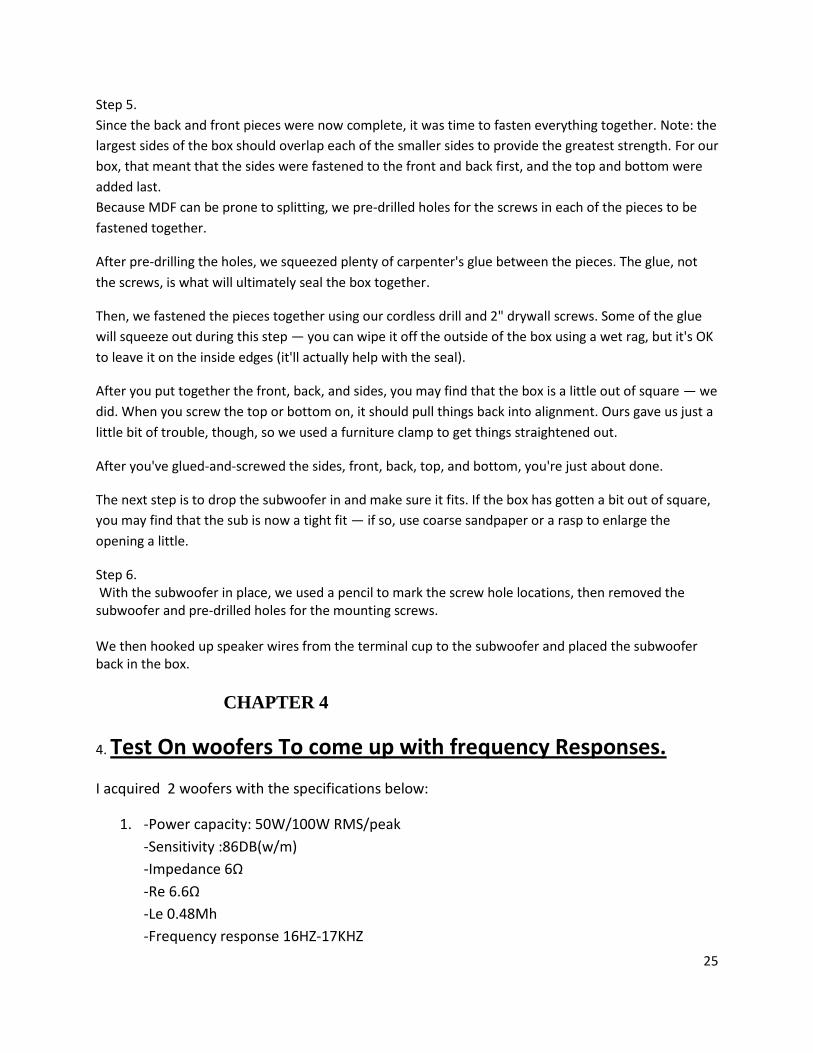
4. Test On woofers To come up with frequency Responses.
I acquired 2 woofers with the specifications below:
1. -Power capacity: 50W/100W RMS/peak
-Sensitivity :86DB(w/m)
-Impedance 6Ω
-Re 6.6Ω
-Le 0.48Mh
-Frequency response 16HZ-17KHZ
26
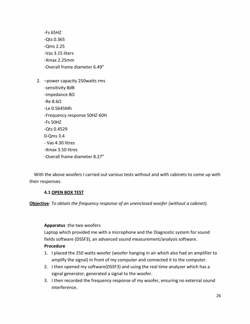
-Fs 65HZ
-Qts 0.365
-Qms 2.25
-Vas 3.15 liters
-Xmax 2.25mm
-Overall frame diameter 6.49”
2. –power capacity 250watts rms
-sensitivity 8dB
-impedance 8Ω
-Re 8.6Ω
-Le 0.5645Mh
-Frequency response 50HZ-60H
-Fs 50HZ
-Qts 0.4529
0-Qms 3.4
- Vas 4.30 litres
-Xmax 3.50 litres
-Overall frame diameter 8.27”
With the above woofers I carried out various tests without and with cabinets to come up with
their responses.
4.1 OPEN BOX TEST
Objective: To obtain the frequency response of an unenclosed woofer (without a cabinet).
Apparatus :the two woofers
Laptop which provided me with a microphone and the Diagnostic system for sound
fields software (DSSF3), an advanced sound measurement/analysis software.
Procedure
1. I placed the 250 watts woofer (woofer hanging in air which also had an amplifier to
amplify the signal) in front of my computer and connected it to the computer.
2. I then opened my software(DSSF3) and using the real time analyzer which has a
signal generator, generated a signal to the woofer.
3. I then recorded the frequency response of my woofer, ensuring no external sound
interference.
27
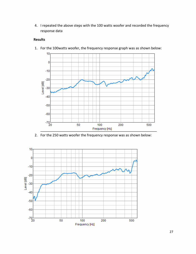
4. I repeated the above steps with the 100 watts woofer and recorded the frequency
response data
Results
1. For the 100watts woofer, the frequency response graph was as shown below:
2. For the 250 watts woofer the frequency response was as shown below:

28
4.2 CLOSED BOX TEST
Objective: To obtain frequency response of a woofer driver enclosed in a very large cabinet and
a very small cabinet.
Apparatus: two woofers enclosed in very small cabinets (smaller than the ideal
enclosure size for the woofer drivers)
Laptop which provided me with a microphone and the
DSSF3 software (an advanced sound measurement/analysis software).
Procedure
1. I put the woofer fixed to it’s enclosure in open air away from any external noise
And ensured there is no any sound reflecting surface around.
2. I then connected my laptop via an amplifier to the 250 watts woofer.
3. I then opened up my DSSF3 software which I used to generate a signal to my woofer.
4. I ensured the woofer is directly close to the laptops’ microphone
5. I then recorded the frequency response graph
6. I repeated the above steps with the 100watts woofer
7. I then repeated the above 6 steps with a very large woofer enclosure.
Results
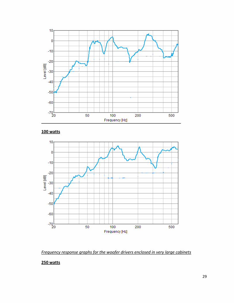
Frequency response graphs for the woofer drivers enclosed in small cabinets:
250 watts
29
100 watts
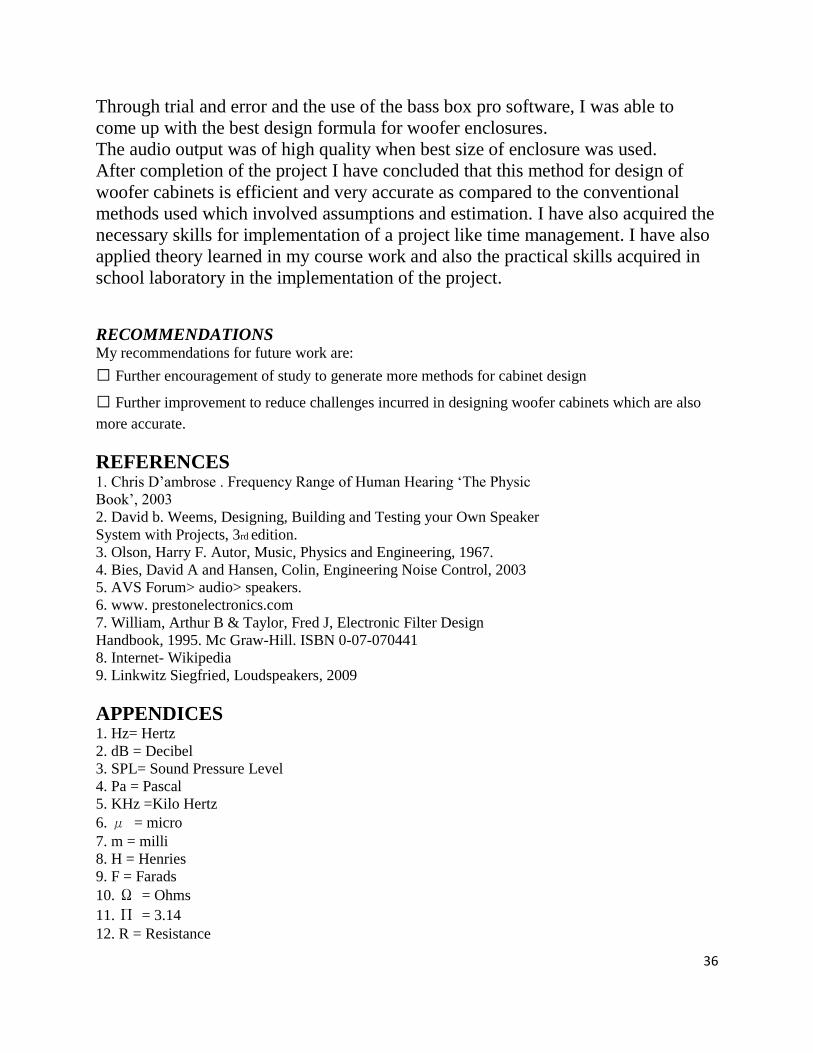
Frequency response graphs for the woofer drivers enclosed in very large cabinets
250 watts

30
100 watts
Discussion
From the above results, It was observed that the size of the cabinet greatly affects the
frequency response of my woofer drivers

31
The frequency response curve of a woofer driver without any enclosure was not flat at
all, it had bumps at several frequencies, it had roll-offs. In a nutshell the response was
not ideal.
The frequency response curve of a woofer driver with a very small enclosure cabinet
had the dB of some frequencies to be higher compared to the rest of the frequencies.
The frequency response curve of a woofer driver with a very large enclosure cabinet had
an almost flat curve and had no roll-offs.
I also realized that there were some echoes being produced by the very large cabinet.
Conclusion
From the above, I came to a conclusion that the efficiency of a woofer system is directly
proportional to its cabinet volume, the large cabinet facilitated production of a good
bass for the driver, with an almost flat response. This is solely because it (the large
cabinet) provided sufficient volume of air behind the driver.
Despite the fact that the large cabinet had good response, A fairly large one(optimum
size) is important to avoid the production of the echoes.
I therefore proceeded to come up with cabinets for my woofer drivers which would
provide optimum almost perfect sound response.
CHAPTER 5
Cabinet Design Using The Bass Box Pro 5.1 Introduction BassBox Pro is a state-of-the-art speaker enclosure design program. It is used around the world by professional and amateur speaker system designers to design world class speaker boxes. BassBox Pro is very versatile and can be used to design speakers for a wide variety of applications including home hi-fi, home theater, car, truck, van, pro sound reinforcement, recording studio monitors, stage monitors, PA, musical instruments, etc.

32
BassBox Pro has many features that make it very easy to learn and use. For example, when the program is first run, a Welcome window (shown below) will appear to help you configure the program and introduce you to its on-screen manual.
The on-screen manual (shown below) is extensive and contains most of the same information as the beautiful 364 page printed manual. Both the on-screen and printed manuals are the best in the industry and include a "Box Designer's Guide", "Sample Designs" and "BassBox Pro Reference". There are many ways to begin a speaker design with BassBox Pro, including the use of its innovative Design Wizard. In general, speaker design involves the following steps:

33
1. Enter the driver parameters such as Fs, Vas and Qts. BassBox Pro's driver database
contains parameters for thousands of drivers.
2. Calculate the box volume and tuning. This is very easy with the program's helpful
"Suggest" button. It will cause BassBox Pro to recommend a box that will produce a
smooth bass response.
3. Evaluate the performance with the graphs. This can include the effects of the acoustical
environment. For example, BassBox Pro can estimate the in-car response in the graphs to
show how the speaker will sound to passengers inside a car.
Each box design can be saved and re-opened or re-used later. As many as ten different designs
can be open at the same time. Box designs can also be duplicated so that driver or box
information does not need to be re-entered.
5.2 Procedure After feeding the parameters of the drivers into the Bass box pro software The software gave me the dimensions of my woofer cabinet for optimum response Simulated Results for the 100 watts woofer, the dimensions were: height=196.5mm width=75.07mm length=121.5mm

34
5.3 Data Analysis
for the 250 watts woofer, the dimensions were: length:119.6mm width:73.89mm depth:193.4mm internal volume Vb:1.709 Qtc:1.259 QL:7 F3:60.9HZ

35
Practical Results For the 250watts
for the 100 watts driver
CONCLUSION AND RECOMMENDATION The main objective of the project, which was to come up with a cabinet design for
my woofer drivers which would have optimum sound response was achieved.
36
Through trial and error and the use of the bass box pro software, I was able to
come up with the best design formula for woofer enclosures.
The audio output was of high quality when best size of enclosure was used.
After completion of the project I have concluded that this method for design of
woofer cabinets is efficient and very accurate as compared to the conventional
methods used which involved assumptions and estimation. I have also acquired the
necessary skills for implementation of a project like time management. I have also
applied theory learned in my course work and also the practical skills acquired in
school laboratory in the implementation of the project.
RECOMMENDATIONS My recommendations for future work are:
Further encouragement of study to generate more methods for cabinet design
Further improvement to reduce challenges incurred in designing woofer cabinets which are also
more accurate.
REFERENCES 1. Chris D‟ambrose . Frequency Range of Human Hearing „The Physic
Book‟, 2003
2. David b. Weems, Designing, Building and Testing your Own Speaker
System with Projects, 3rd edition.
3. Olson, Harry F. Autor, Music, Physics and Engineering, 1967.
4. Bies, David A and Hansen, Colin, Engineering Noise Control, 2003
5. AVS Forum> audio> speakers.
6. www. prestonelectronics.com
7. William, Arthur B & Taylor, Fred J, Electronic Filter Design
Handbook, 1995. Mc Graw-Hill. ISBN 0-07-070441
8. Internet- Wikipedia
9. Linkwitz Siegfried, Loudspeakers, 2009
APPENDICES 1. Hz= Hertz
2. dB = Decibel
3. SPL= Sound Pressure Level
4. Pa = Pascal
5. KHz =Kilo Hertz
6. μ = micro
7. m = milli
8. H = Henries
9. F = Farads
10. Ω = Ohms
11. Π = 3.14
12. R = Resistance
37
13. L= Inductance
14. C = Capacitance
15. ZO= Impedance
16. fc = Cross over frequency/ Cut off frequency
17. V= Voltage
18. P = Power
19. f = frequency
20. LPF = Low pass filter
21. HPF = High pass filter
22. BPF = Band pass filter
23. FL= Lower cut off frequency
24. FH = Upper cut off frequency
25. W= Watts
26. rms = root mean square