design of slip horizontal table system for shaker
TRANSCRIPT
SAKARYA UNIVERSITY
JOURNAL OF SCIENCE
e-ISSN: 2147-835X
http://www.saujs.sakarya.edu.tr
Recieved Accepted DOI
2018-03-20 2018-03-27 10.16984/saufenbilder.407959
Design of Slip Horizontal Table System for Shaker
Ömer Kadir Morgül1
Abstract
Shakers can produce vibration functions at the desired frequencies and amplitudes according to the
vibration standards. Also, shakers have the same working principle with devices of hydraulic, mechanical
pneumatic, electromagnetic etc. Shakers can produce vibration in the vertical and horizontal direction
depending on the type of table. The test sample is fixed on the table with fixture. In this study, the
appropriate slip table was designed and manufactured in order to improve test capability of shaker.
Therefore shaker had the capability of vibration drive in the horizontal directions for test sample. Finite
element method (FEM), modal analysis, harmonic analysis and vibration measurements were applied to
assess vibration analysis. After, results of FEM and confirmation experimental were in a good agreement
with each other, the design of vibration shaker table system was manufactured.
Keywords: shaker, slip table, modal test, vibration analysis
1. INTRODUCTION
The products using in the different industrial area
have been tested to verification design and to
achieve vibration standard depend on the
international tests standard. The most important
and most common of these test have been vibration
test. Vibration test has been used under the actual
operating conditions to determine weakness of the
design and the structural strength [1,2].
The strength of the products and load that can be
applied on the products were determined depend
on the test standard [3,4] or data that can be
gathered under the actual operating conditions. All
experiments were carried out under the test
standard [5,6] with using data acquisition-
processing equipment, control equipment,
accelerometers, load meters, shakers, and the
heating cabin.
1 Sakarya Unv., Eng. Fac. Mech. Eng. Dept., [email protected]
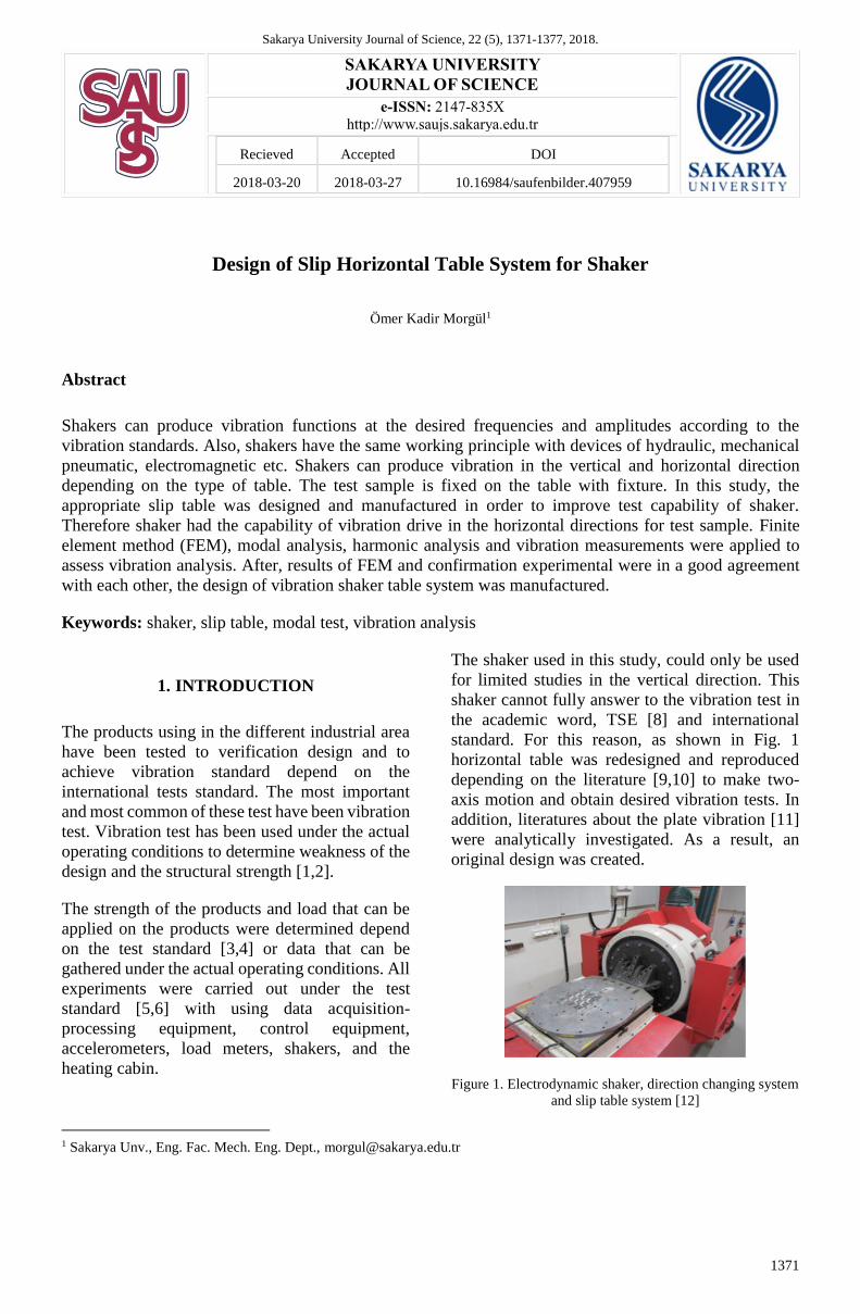
The shaker used in this study, could only be used
for limited studies in the vertical direction. This
shaker cannot fully answer to the vibration test in
the academic word, TSE [8] and international
standard. For this reason, as shown in Fig. 1
horizontal table was redesigned and reproduced
depending on the literature [9,10] to make two-
axis motion and obtain desired vibration tests. In
addition, literatures about the plate vibration [11]
were analytically investigated. As a result, an
original design was created.
Figure 1. Electrodynamic shaker, direction changing system
and slip table system [12]
1371
Sakarya University Journal of Science, 22 (5), 1371-1377, 2018.
Morgül, Ö. / Design of Slip Horizontal Table System For Shaker
The designed slip table will also be exposed to
vibration. Therefore, the natural frequencies of the
table need to be determined. If the system was
driven at these frequencies, the test results can be
adversely affected. Thus, the design of vibration
test fixtures was very important issue [13]. Before
the test, products were connected to the vibration
table. All test must be applied towards the
international standards. The connection must be
applied according to the actual operating
condition, when the products were connected to
the vibration table.
In this study, the appropriate slip table was
designed and manufactured for shakers in order to
increase shaker’s test capability of horizontal
direction. The production of the magnesium alloy
slip plates with the technical drawings was carried
out by special casting method at VIG Metals Inc.
facilities in Kütahya. VIG Metals Inc., which
produces the first and only magnesium alloy in
Turkey, which can handle the business in-house, is
an expert and experienced company. The
manufactured table assembled to the shaker and
vibration tests were carried out. The experimental
results shown that the desired material strength
properties and vibration parameters were in a good
agreement with each other. In addition, this study
shown a way about design and production of the
shaker slip table.
2. HORIZONTAL SLIP TABLE DESIGN
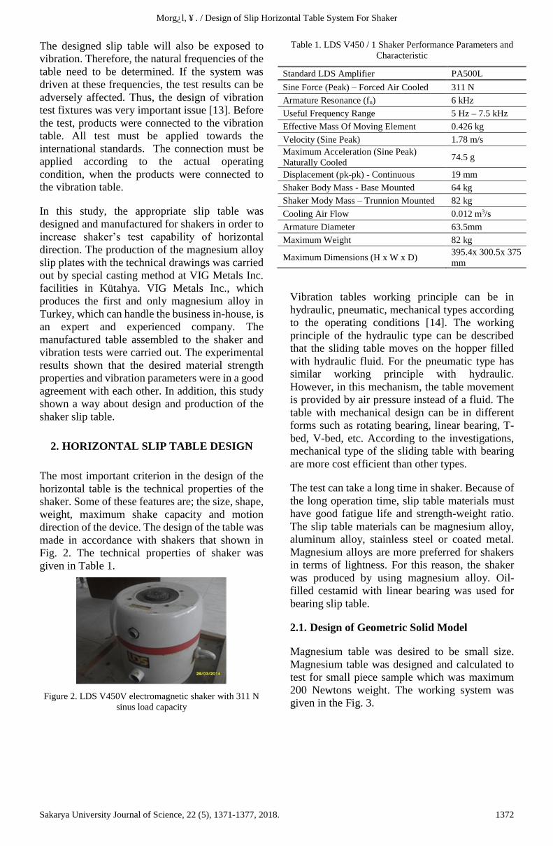
The most important criterion in the design of the
horizontal table is the technical properties of the
shaker. Some of these features are; the size, shape,
weight, maximum shake capacity and motion
direction of the device. The design of the table was
made in accordance with shakers that shown in
Fig. 2. The technical properties of shaker was
given in Table 1.
Figure 2. LDS V450V electromagnetic shaker with 311 N
sinus load capacity
Table 1. LDS V450 / 1 Shaker Performance Parameters and
Characteristic
Standard LDS Amplifier PA500L
Sine Force (Peak) – Forced Air Cooled 311 N
Armature Resonance (fn) 6 kHz
Useful Frequency Range 5 Hz – 7.5 kHz
Effective Mass Of Moving Element 0.426 kg
Velocity (Sine Peak) 1.78 m/s
Maximum Acceleration (Sine Peak)
Naturally Cooled 74.5 g
Displacement (pk-pk) - Continuous 19 mm
Shaker Body Mass - Base Mounted 64 kg
Shaker Mody Mass – Trunnion Mounted 82 kg
Cooling Air Flow 0.012 m3/s
Armature Diameter 63.5mm
Maximum Weight 82 kg
Maximum Dimensions (H x W x D) 395.4x 300.5x 375
mm
Vibration tables working principle can be in
hydraulic, pneumatic, mechanical types according
to the operating conditions [14]. The working
principle of the hydraulic type can be described
that the sliding table moves on the hopper filled
with hydraulic fluid. For the pneumatic type has
similar working principle with hydraulic.
However, in this mechanism, the table movement
is provided by air pressure instead of a fluid. The
table with mechanical design can be in different
forms such as rotating bearing, linear bearing, T-
bed, V-bed, etc. According to the investigations,
mechanical type of the sliding table with bearing
are more cost efficient than other types.
The test can take a long time in shaker. Because of
the long operation time, slip table materials must
have good fatigue life and strength-weight ratio.
The slip table materials can be magnesium alloy,
aluminum alloy, stainless steel or coated metal.
Magnesium alloys are more preferred for shakers
in terms of lightness. For this reason, the shaker
was produced by using magnesium alloy. Oil-
filled cestamid with linear bearing was used for
bearing slip table.
2.1. Design of Geometric Solid Model
Magnesium table was desired to be small size.
Magnesium table was designed and calculated to
test for small piece sample which was maximum
200 Newtons weight. The working system was
given in the Fig. 3.
1372Sakarya University Journal of Science, 22 (5), 1371-1377, 2018.
Morgül, Ö. / Design of Slip Horizontal Table System For Shaker
Figure 3. Schematic representation of the shaker system
Shaker solid model was generated based on the
shaker actual dimension. For connection of the slip
table with the connector-2 piece as shown in Fig.
4, 3 holes with 10 mm diameter were drilled and 3
pieces M10 bolts were used. The test sample
assembled on the slip table with M6 bolts. As can
be shown in Fig. 5 to increase the fatigue life of
the design, we avoided from sharp edges that
caused stress accumulation.
Figure 4. Connector-2 part
Figure 5. Technical drawing of horizontal table
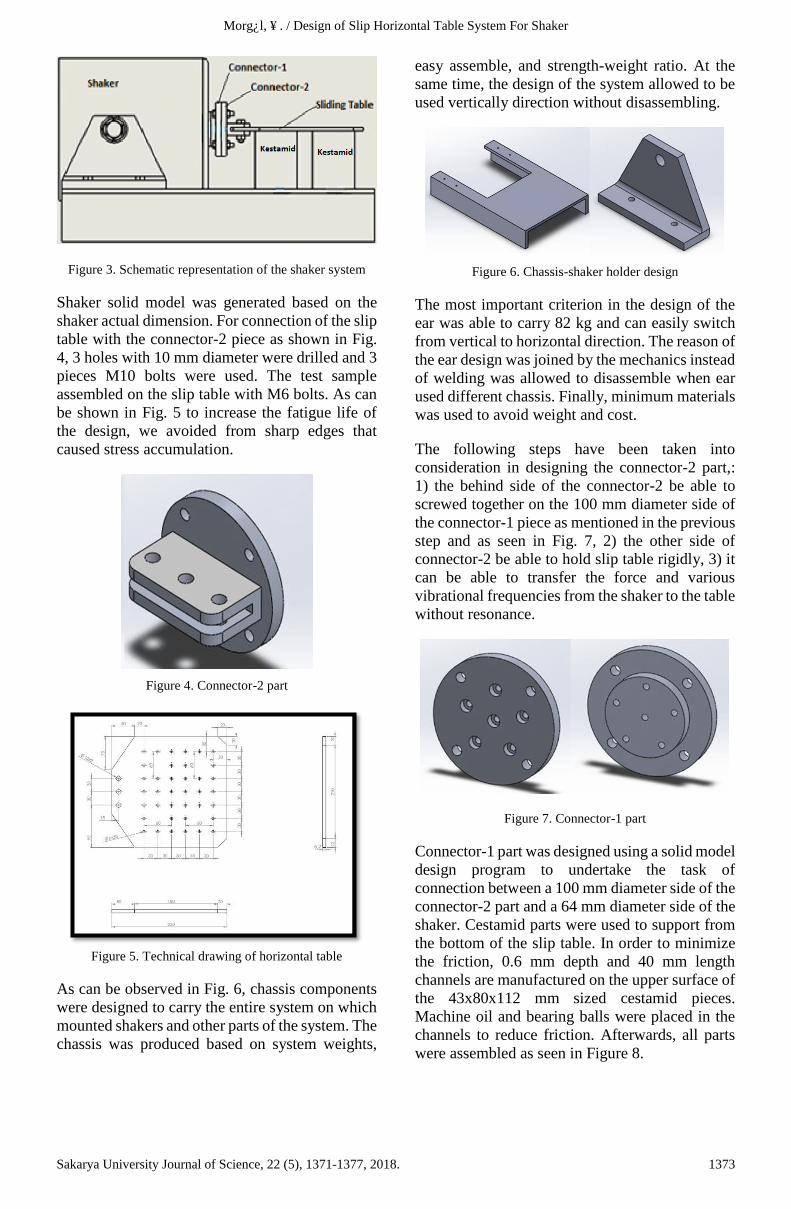
As can be observed in Fig. 6, chassis components
were designed to carry the entire system on which
mounted shakers and other parts of the system. The
chassis was produced based on system weights,
easy assemble, and strength-weight ratio. At the
same time, the design of the system allowed to be
used vertically direction without disassembling.
Figure 6. Chassis-shaker holder design
The most important criterion in the design of the
ear was able to carry 82 kg and can easily switch
from vertical to horizontal direction. The reason of
the ear design was joined by the mechanics instead
of welding was allowed to disassemble when ear
used different chassis. Finally, minimum materials
was used to avoid weight and cost.
The following steps have been taken into
consideration in designing the connector-2 part,:
1) the behind side of the connector-2 be able to
screwed together on the 100 mm diameter side of
the connector-1 piece as mentioned in the previous
step and as seen in Fig. 7, 2) the other side of
connector-2 be able to hold slip table rigidly, 3) it
can be able to transfer the force and various
vibrational frequencies from the shaker to the table
without resonance.
Figure 7. Connector-1 part
Connector-1 part was designed using a solid model
design program to undertake the task of
connection between a 100 mm diameter side of the
connector-2 part and a 64 mm diameter side of the
shaker. Cestamid parts were used to support from
the bottom of the slip table. In order to minimize
the friction, 0.6 mm depth and 40 mm length
channels are manufactured on the upper surface of
the 43x80x112 mm sized cestamid pieces.
Machine oil and bearing balls were placed in the
channels to reduce friction. Afterwards, all parts
were assembled as seen in Figure 8.
1373Sakarya University Journal of Science, 22 (5), 1371-1377, 2018.

Morgül, Ö. / Design of Slip Horizontal Table System For Shaker
Figure 8. Cestamid oil reservoir and system assembly
3. STRUCTURAL AND VIBRATION
ANALYSIS OF PLATES
3.1. Operating Parameters
The maximum load was applied by the shakers to
the sliding table was up to 300 Newton. This force
was applied as distributed load, from the side to
which the shaker was connected to the table.
Therefore, the force is defined as distributed load
during vibration analyzing. The solid model of the
sliding table was generated and then transferred to
the ANYSN [16] for vibration analysis.
3.2. Static Analysis
As can be seen Fig. 9, the horizontal table was
meshed according to the surface features.
Figure 9. Finite element model of slip table
In the static analysis, the table was modeled as a
console and the deformations from the weight of
the table were investigated. The horizontal table
with static analysis is shown in Figure 10. The fact
that the maximum deformation is too small
suggests that the tables are sufficiently rigid.
Figure 10. Results of static analysis of slip table
3.3. Modal Analysis
In this study, the modal characteristic of the slip
table model was investigated. As a result of
analysis 10 natural frequencies were obtained.
This natural frequency corresponding to the 10
mode shapes were examined. The results belong
to the sliding table can be seen in Table 2.
Table 2. Modal analysis results of slip table
Mode Shape Natural
Frequency (Hz)
Normalized
Deformation
1 353 1
2 618 0,96
3 798 0,9
4 820 1,1
5 1066 1,46
6 1142 0,997
7 1151 1,11
8 1186 0,699
9 1496 0,83
10
As can be seen in Fig. 11,12,13 and 14, the first 4
mode shapes of the slip table was obtained during
the working conditions.
Figure 11. 1st mode shape of slip table
Figure 12. 2nd mode shape of slip table
1374Sakarya University Journal of Science, 22 (5), 1371-1377, 2018.

Morgül, Ö. / Design of Slip Horizontal Table System For Shaker
Figure 13. 3rd mode shape of slip table
Figure 14. 4th mode shape of slip table
Based on the modal analysis, the results were in a
close to each other for sliding table which was
made of magnesium even if maximum
deformation was applied on the sliding table.
3.4. Harmonic Response Analysis
The results of amplitudes corresponding to the
natural frequencies, which was generated by using
harmonic drive, were observed. One of the ten
model was obtained during the actual operating
condition. It was the main mode shape. As can be
seen in Fig. 15, the main mode frequency was 820
Hz represented at the fourth mode.
Figure 15. The amplitude-frequency curve obtained in the
harmonic analysis for the slip table
4. EXPERIMENTAL STUDIES
To obtain vibration measurements manufactured
parts were assembled as shown in Fig. 16.
Figure 16. Assembly of slip table, connection parts shakers
The measurement plan was prepared as shown in
Figure 17 to obtain the vibration measurements
from the slip table.
Figure 17. Vibration measurement points of slip table
SD: Vertical axis acceleration measurement point
of shaker,
SY: Horizontal axis acceleration measurement
point of shaker
TM: Vertical axis acceleration measurement point
of table center
K1;K2;K3;K4: Vertical axis acceleration
measurements points of the corner points of the
slip table.
1375Sakarya University Journal of Science, 22 (5), 1371-1377, 2018.

Morgül, Ö. / Design of Slip Horizontal Table System For Shaker
TSOLY: Horizontal axis acceleration
measurements point of the farthest left corner
point of the slip table.
TOY: Horizontal axis acceleration measurements
point of the farthest middle point of the slip table.
TSAGY: Horizontal axis acceleration
measurements point of the farthest right corner
point of the slip table.
It was determined that the measurements taken by
the harmonic test were in agreement with the
modal analysis. The 4th mode corresponds to the
high frequency (820 Hz). However, it is measured
that the vibration peak values are very low due to
the rigidity of the slip tables. So even operating the
shaker at 820 Hz is not a risk. However, the stable
working frequency of the slip tables is already 50
Hz. The vibration measurements taken at 50 Hz
from slip table, are given in Figure 18, Figure 19,
Figure 20 and Figure 21.
Figure 18. Vertical acceleration measurements (K1, K2,
K3, K4 points) of the corner points of the slip table
The RMS values of the points K1, K2 and K3 in
the vertical direction are 0.086, 0.038, 0.040 and
0.202, respectively. As shown in Fig. 18, the RMS
value of the point K4 is higher than the other three
points. When the reason is investigated, it has been
found that K1, K2, K3 points are processed in the
same thickness during manufacturing and the
thickness of K4 point is thicker than the other three
points. An error occurs because the thickness of
the table is not uniform. After measurements, the
plate thickness is uniformed.
Figure 19. Vertical acceleration measurements of the shaker
and slip table center (SD and TM points)
The RMS values taken from points SD and TM are
0.027 and 0.020, respectively, as shown in Figure
19. The acceleration values measured in the
horizontal direction are exactly the same. Thus, it
can be seen that the force generated from the
shaker can be transmitted to the end point of the
table without any interruption as shown in Figure
20. The RMS measurements taken from the TOY
and SY points are 2,031 and 2,033, respectively as
shown in Figure 20.
Figure 20. Acceleration measurements in the horizontal
direction (TOY and SY points) of shaker and slip table end,
center and edge point,
As a result of the measurements taken from the end
point of the table at the horizontal axis, the same
results were obtained at the three points of the slip
table and the results showed the slip table have the
same stiffness at every point in the axial direction
as seen in Fig. 21. The RMS measurements taken
at the TOY, TSAGY and TSOLY points, are
2.031, 2.014 and 2.050, respectively as shown in
Fig. 21.
1376Sakarya University Journal of Science, 22 (5), 1371-1377, 2018.

Morgül, Ö. / Design of Slip Horizontal Table System For Shaker
Figure 21. Acceleration measurements in the horizontal
direction (TOY, TSAGY, TSOLY points) of the slip table
right, left and center points
5. CONCLUSIONS
In this study, a slip table was designed to allow
horizontal axial vibration test. Modal and
harmonic analyses of the system were carried out
using various analysis programs. As a result of the
analyses, AZ91D magnesium alloys were found
suitable for slip table material in terms of rigidity
and lightness. Machining operations such as
surface finishing, chamfering, hole drilling, etc. of
the casting tables were carried out at VIG Metals
Inc. Gebze facilities. According to the acceleration
and displacement values obtained as a result of the
vibration tests carried out, it has been found that
the rigidity of the table and the natural frequencies
are suitable for vibration tests.
ACKNOWLEDGMENTS
The author gratefully acknowledge the technical
support provided by VIG Metals Inc., SAUBAP
and TUBITAK 2209-B, Project No:
1139B411700224.
REFERENCES
[1] Vibration Testing, Bruel&Kjaer, 1983.
[2] K. G. McConnell, “Read Vibration Testing:
Theory and Practice”, Wiley, 2008.
[3] Anon., NASA-HDBK-7005, Dynamic
Environmental Criteria, March 13, 2001.
[4] IEC 60068-2-6 Part 2:”Environmental
testing - Vibration (sinusoidal)”.
[5] IEC 61373: “Railway applications. Rolling
stock equipment. Shock and vibration tests”.
[6] ANSI S2.26: American National Standard
Vibration Testing Requirements and
Acceptance Criteria for Shipboard
Equipment.
[7] https://vibrationdata.wordpress.com/ 2016/
10/31/lds-v-8900-shaker-table/.
[8] TS EN 60034-14, “Döner Elektrik
Makinaları- Bölüm 14: Mil Yüksekliği 56
mm ve daha yüksek olan bazı makinalarda
mekanik titreşim - Titreşimin Ölçülmesi
Değerlendirilmesi ve Sınırları”.
[9] Levive Sheldon, Vibration Test Fixtures:
Theory and Practice.
[10] F. Poncelet, F. Marin, C. Fleury and JC.
Golinval, Optimal Design of Fixtures for
Vibration Testing of Structures on Electro-
Dynamic Shaker, ICSV, 2005, Lisbon.
[11] H. Dal, Ö.K. Morgül, Vibrations of
elastically restrained rectangular plates,
Scientific Research and Essays, Vol. 6(34),
6811-6816, 2011.
[12] Falk Per, Test Fixtures for Vibration Testing
of Components, Degree Project, in Vehicle
Engineering, Second Level, Stocholm,
Sweden, 2015.
[13] The Importance of Fixture Design in
Vibration Testing, DATASYST
Engineering&Testing Services, Inc.
[14] Slip Tables Product Guide, ETS Solutions.
[15] Technical Analysis of Team T-Film Slip
Table, TEAM Vibration Testing Equipment,
1989.
[16] ANSYS 17.2 Release Notes, 2016.
.
1377Sakarya University Journal of Science, 22 (5), 1371-1377, 2018.