design of single piles, small pile groups, … single piles, small pile...page a1-1 design of single...
TRANSCRIPT
Page A1-1
DESIGN OF SINGLE PILES, SMALL PILE GROUPS, AND
WIDE PILED FOUNDATIONS
Bengt H. Fellenius, Dr. Tech., P.Eng.
Consulting Engineer, Sidney, BC, Canada
ABSTRACT. The response of single piles and small pile groups to load differs considerably from that
of wide piled foundations. Single piles interact with settlements of the soil layers surrounding the
piles and develop a force and settlement equilibrium (neutral plane) which location to a large extent
depends on the pile toe response to the soil forces and movements. Similar to single piles, perimeter
piles of a wide pile group in subsiding soils will be affected by increasing load due to negative skin
friction. They will, therefore, appear softer than the interior piles, which., in contrast, are mostly
unaffected by shaft resistance (or negative skin friction). Indeed, the load applied to a wide pile
group will more or less unimpededly be transferred down the pile and only be reduced by shaft
resistance immediately above the pile toe. The equilibrium between the toe penetration of the
interior piles and the upward compression of the soil surrounding the piles determines the load-
transfer movement of the wide piled foundation.
All piles are of course affected by the settlement of the soil below the pile toe level due to
occurrences, such as regional settlement and stress changes due to adjacent foundations, fills,
excavations, etc. Wide pile piled-foundations will, in contrast to single piles, also be affected by the
compression of the soils below the pile toe level due to the sustained load on the foundation.
For pile groups in non-subsiding soil, the response of perimeter piles is stiffer than that of the
interior piles. Thus, in order to minimize differential settlement of the piles across the pile raft, the
perimeter piles may have to be installed shorter than the interior piles. On the other hand, pile
groups in subsiding soil, may need to have the perimeter piles installed longer than the interior piles.
Key Words. Single piles, piled foundations, drag force, settlement, wide pile groups.
INTRODUCTION
Conventionally, pile design involves establishing the allowable load (i.e., maximum
working load) for the piles by applying a factor of safety to the capacity of a single
pile, or, in LRFD, applying a resistance factor to the capacity to establish the factored
resistance. Capacity is easy enough to calculate by general soil mechanical principles,
but calculated and actual values are often rather far apart, which implies a
troublesome uncertainty of the design. To alleviate the gap between theory and
practice, static loading tests are usually carried out and the pile capacity is
determined from the pile-head load-movement measured in the test. Capacity may
be thought of as the ultimate resistance of the pile. However, only few tests will
clearly establish an ultimate resistance. Therefore, numerous definitions of capacity
are employed as based on either the shape of the load-movement curve or on
certain geometric features of the pile, notably size and length. It is a troublesome
fact that few engineers agree on what definition to apply. The few standards and
codes recommending a definition are not helpful. For example, the Eurocode states

Page A1-2
that the pile capacity is the load that produces a pile head movement equal to a
tenth of the pile diameter. Let alone that this code does not state whether for a
square pile the diameter is the face-to-face or the corner-to-corner distance, a piled
foundation does not really care one whit about the size of the diameter of the
supporting pile. It cares about the settlement of the foundation, caused by the load
applied to the pile(s) in combination with any environmental load from the soil
surrounding the particular foundation. The recent shift from global factor of safety to
limit states design has not improved the practice in this regard.
In the long past, foundations were designed for expected settlement, even
though, settlement calculations were more ambiguous estimates than results of
analysis. As geotechnical engineering advanced, it became relatively easy to calculate
ultimate resistance which led to the development of the now ubiquitous factor-of-
safety approach. That is, the design principle became: calculate or find out at what
load the foundation would surely collapse and then choose a working load that is
half, or a third, or even less, and trust that the foundation settlement will be no more
than acceptable. This approach usually results in a safe foundation, albeit more often
than not a very expensive one. Frequently, however, the performance of a
so-designed foundation turns out to be less than satisfactory and, indeed, sometimes
not safe. Today, geotechnical engineering design is able to address for settlement
confidently and directly, and there is little reason for continuing to base a foundation
design on the worse-for-wear capacity approach.
SOIL AND PILE RESPONSE TO LOADING A PILED FOUNDATION
When applying load from a structure to a foundation supported on piles, the piles
are immediately axially compressed (small amount) and pushed somewhat into the
ground as the load is transferred from the pile head down the pile and out into the
soil. The transfer to the soil occurs by shear forces along the pile shaft associated
with relative movement between the pile shaft and the soil. What load not resisted
by shaft resistance reaches the pile toe and causes the pile toe to move a small
distance into the ground. In short, the process establishes a balance, an equilibrium
between the applied load and the shaft and toe resistances is mobilized. The
associated movements are called load-transfer movements.
A pile is several orders of magnitude stiffer than soil and will not change length
much during the years of service after erection of the supported structure. However,
even stiff, "non-settling" soils surrounding the pile(s) will lose volume and settle over
time, be it ever to slightly. Additional long-term soil settlement often occurs due to
fill having placed over the site, or to regional subsidence caused by mining of water.
The soil settlement will cause the working load applied to the pile move deeper
down the pile, and the shaft shear along the upper portion of the pile, initially acting

Page A1-3
in positive direction, will change to acting in negative direction, which adds force
(drag force) to the axial load in the pile. In time, a force equilibrium will develop
between accumulated negative skin friction (the drag force) and positive shaft
resistance. In the process, the pile toe load will increase and additional toe
penetration will occur.
The force equilibrium depth is also the depth to a "settlement equilibrium"—both
equilibrium locations are referred to as the 'neutral plane'—and it is where the pile
and the soil settle equally. If the neutral plane is where the soil settlement is large,
the piled foundation will experience large settlement. Conversely, if the settlement at
the neutral plane is small, the foundation settlement will not be an issue.
It follows that the design of the piled foundation on a single pile or a small group
of piles must involve determining the location of the neutral plane and the
magnitude of soil settlement at the neutral plane. The analysis and design of wide
groups require a slightly different approach.
FOUNDATIONS ON SINGLE PILES OR ON NARROW GROUPS OF PILES
The left graph in Figure 1 shows the load distribution for a 25 m long pile installed in
a two-layered soil. The curve labeled 'Initial" pertains to the distribution immediately
after the structure has been placed on the piled foundations. The curve labeled
"long-term" shows the distribution after the soil around the pile has settled and
negative skin friction has been introduced and a neutral plane—force equilibrium—
has materialized. The axial load in the pile has increased due to accumulated
negative skin friction—drag force. The transfer of load down the pile has resulted in
additional pile toe resistance and pile toe penetration.
As is the case for all piles other than very slender and/or very long piles, the drag
force is of no consequence for the pile geotechnical design. It is an environmental
force that merely acts as an axial prestress, if anything, it is a beneficial aspect for the
foundation, because it provides a pile with a stiffer response to transient loads.
The key aspect of the long-term development is the toe resistance indicated in
the graph. The larger or smaller the toe resistance, the lower or higher the location of
the neutral plane. Of course, the magnitude of the toe resistance is determined by
the pile toe load-movement response, which is illustrated at the bottom of the right
graph. Notice that the pile toe movement graph is offset to start at the soil
movement at the pile toe.
The right side graph in Figure 1 shows the distribution of settlement in the soil
surrounding the pile. For single piles and narrow or small pile groups, the load on the
pile produces load-transfer movement, which is normally quite small, but no (or only
insignificant) settlement due to compression of the soil below the pile-toe level (the
soil volume involved is too small).

Page A1-4
Fig. 1 Load and settlement distribution and long-term development of a
neutral plane for a 25 m long pile with illustration of toe response.
For a single pile or a narrow (small) group of piles, settlement beyond the load-
transfer movement is caused by other factors, e.g., a fill on the ground surface or
lowered groundwater table, etc. At the neutral plane, as mentioned, the soil and the
pile settle equally.
In the process, the pile toe is forced into the soil, which builds up a toe resistance
according to the particular pile-toe load-movement response illustrated in the
diagram at the bottom.
The key to the interaction between the two main graphs of the figure is (1) the
toe resistance in the left graph must always match the toe movement in the right
graph and (2) the toe force controls the location of the force equilibrium. Thus, the
figure illustrates the loop between pile force and pile movements that establishes the
equilibriums and determines the position of the neutral plane and the settlement of
the pile head.
There are important details to consider. For example, the transition of fully
mobilized negative skin friction to fully mobilized positive shaft resistance does not
occur suddenly, but occurs along a certain length, a transfer zone. This is why the
long-term load distribution is curved at the neutral plane, as opposed to exhibiting a
kink. If the soil settlement is large, the transition zone is short. If settlement is small,
the zone can be quite long. This, of course, affects the magnitude of the drag force.
The drag force is often thought of as similar in nature to a load from the
supported structure. This is incorrect. The drag force is only of concern for the axial
0
5
10
15
20
25
0 500 1,000 1,500
DE
PT
H (
m)
LOAD (kN)
0
5
10
15
20
25
0 50 100 150
SETTLEMENT (mm)
0 25 50L
OA
D
LO
AD
Toe Response
Neutral Plane
Qd
500 kN
500 kN
500 kN
LOAD (kN)
500 kN
0 - 15 m CLAY
15 - >25 m SANDInitial
Long-term
Settlementat pile head
PILE SOIL
MOVEMENT (mm)

Page A1-5
strength of the pile and it needs only to be considered for very long and slender
piles.
Note, the about 80-kN long-term toe resistance indicated in the figure is not an
"ultimate toe resistance". The toe resistance in the test is much larger than the
100 kN mobilized in the long-term condition, because toe resistance increases
gradually with the imposed toe penetration. No "ultimate toe resistance" will develop
for a pile.
A conventional assessment of the results of a static loading test on the example
pile would indicate, depending on the chosen definition of capacity, that a sustained
working load, Qd, of 700-kN, as indicated, is acceptable. However, capacity
determined by any definition is rather immaterial. For instance, if the ultimate shaft
shear above and below 15 m depth happens to be twice that used for the example
and the toe resistance response is yet the same, the force equilibrium would still be
at the same depth and the load-transfer settlement be no larger or smaller than in
the first analysis (but for a slight increase in pile compression). The capacity will be at
least twice that assumed, though, suggesting a very conservative design. This
disregards that were the shaft shear that much larger, the soil compressibility would
likely be smaller than assumed for the example, i.e., be unrealistic. A similar
calculation, but with the shaft shear smaller than assumed, would also indicate the
same settlement, but that assumption would, again, not be realistic, as the soil
compressibility for such a soft soil would be larger and the settlement at the neutral
plane would very likely be excessive, showing the design to be less than acceptable.
The decisive matter for an analysis applying realistic parameters is whether or not
the settlement is acceptable to the structure supported on the piled foundation.
The approach, summarized above and in the example figure is called the Unified
Design of Piled Foundations, which I first published in 1984 and have since
addressed in various contexts—Fellenius (2017) has a reference list. It is accepted in
many advanced standards and codes, e.g., Canadian and Australian codes, US Corps
of Engineers, US FHWA standard, etc., though not in all. The next section of this
paper will elaborate on how to apply the Unified Method to the response of piled
foundations on wide pile groups.
FOUNDATIONS ON WIDE GROUPS OF PILES
The response of a single pile or narrow piled foundation to an applied load is fairly
simple, as described in the foregoing. The response of a wide group is a good deal
more complex, however. Sometimes, the usually larger settlement response of a
piled foundation, as opposed to that of a single pile supporting the same load, is
taken as equal to the accumulated movements from each single-pile load-movement
response of the piles in the group. This is a fallacious approach that has led to the

Page A1-6
development of many more or less complex methods for calculating settlement of a
piled foundation, none correct (Fellenius 2016).
Of course, a wide pile group will stress the soil below the pile toe level and, this
will cause settlement to develop below the pile-toe level of the group and, to some
extent, also to the surrounding soils and adjacent foundations. An issue to address is
what is the load transfer movement of the piles within a wide pile group and does a
neutral plane develop for a wide group, and, if so, at what depth?
Sophisticated analysis methods exist that are based on correlating the settlement
of a raft without piles, acting like a footing, to a pile-supported raft with the same
total load. The contact stress under the footing part of the raft is thought to
contribute to the "capacity". The portions of load directed to the piles and to footing
contact stress, whether at sustained or ultimate conditions, are, usually, determined
according to some correlation between the bending stiffness of the raft and the axial
stiffness of the piles.
Upper boundary of pile-soil body—the underside of the raft
If the conditions are such that a neutral plane lies right at the underside of the pile
cap (as would be the case for a "factor of safety" equal to unity or less), it is often
thought that a physical contact and a contact stress would develop that would assist
in supporting the applied load. Thus, that there would be a footing contact stress
below the pile cap (raft) contributing to the bearing of the raft would seem to be a
logical assumption.
If, on applying load to the raft, the strain developed in the soil due to contact
stress would be smaller than the strain in the piles, the soil would compress less than
the pile. However, the common boundary of the pile and the soil (the pile cap) would
then require that load would be transferred from the piles to the soil until the strain
in soil and pile would be equal. If, on the other hand, the soil strain would be larger
than the strain in the piles, the soil would compress more than the piles and contact
stress would disappear. Therefore, the strain in the soil at the underside of a piled
raft must be the same as the strain in the pile.
Ordinarily, the strain introduced in the pile is approximately 100 microstrain. Most
soils surrounding a pile would have a modulus that is three to four orders of
magnitude smaller than the modulus of the pile material. A 100 microstrain soil
stress is negligibly small and, therefore, no appreciable contribution to bearing can
develop due to contact stress unless the pile spacing is very wide.
It is conceivable that some stress will be induced to the soil from the pile further
down, much like the interaction and interplay of stress between the reinforcement
and the concrete in a reinforced concrete element. However, any axial load that is
shed to the soil is then transferred from the soil to a neighboring pile that, in turn
Page A1-7
sends some of its load to the first pile or to other piles. Similar to the case reported
by Okabe (1977), there is then no reduction of load due to shaft resistance.
Thus, when load is applied to a wide piled-supported raft, the resulting
deformation will be similar to that of a single body, a pier, made up of the piles and
the soil in-between the piles.
Lower boundary of pile-soil body—the pile toe level
At the pile toe level, the upward directed stress acting on the soil in-between the
piles will cause an upward push—the soil immediately above the pile toe level will
compress and the toe-level boundary will move upward in relation to the pile. The
soil compression in relation to the pile will be equal to the pile-toe load-transfer
movement and generate a shaft resistance up along the piles, gradually reducing the
vertical stress in the soil by transferring the stress to the piles (Fellenius 2016).
In contrast, shaft shear will develop along the perimeter of the group—the
perimeter of the pier, as it were—due to the downward movement of the pile relative
to the soil. Thus, perimeter piles will appear stiffer than interior piles. On the other
hand, if the soil is affected by general subsidence due to water mining, fills, adjacent
foundations, etc., the perimeter piles will appear softer than the interior piles.
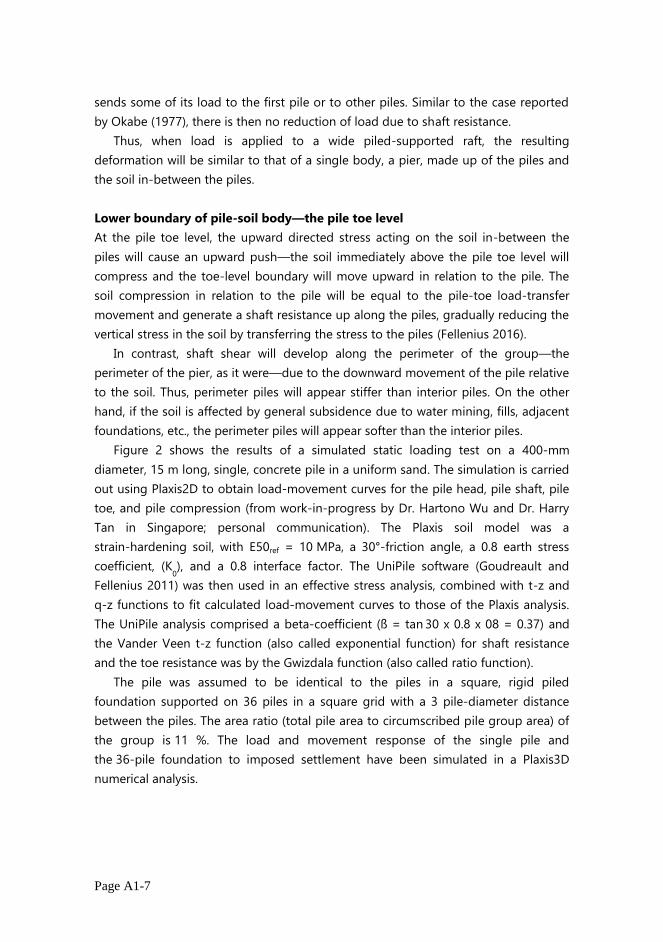
Figure 2 shows the results of a simulated static loading test on a 400-mm
diameter, 15 m long, single, concrete pile in a uniform sand. The simulation is carried
out using Plaxis2D to obtain load-movement curves for the pile head, pile shaft, pile
toe, and pile compression (from work-in-progress by Dr. Hartono Wu and Dr. Harry
Tan in Singapore; personal communication). The Plaxis soil model was a
strain-hardening soil, with E50ref = 10 MPa, a 30°-friction angle, a 0.8 earth stress
coefficient, (K0), and a 0.8 interface factor. The UniPile software (Goudreault and
Fellenius 2011) was then used in an effective stress analysis, combined with t-z and
q-z functions to fit calculated load-movement curves to those of the Plaxis analysis.
The UniPile analysis comprised a beta-coefficient (ß = tan 30 x 0.8 x 08 = 0.37) and
the Vander Veen t-z function (also called exponential function) for shaft resistance
and the toe resistance was by the Gwizdala function (also called ratio function).
The pile was assumed to be identical to the piles in a square, rigid piled
foundation supported on 36 piles in a square grid with a 3 pile-diameter distance
between the piles. The area ratio (total pile area to circumscribed pile group area) of
the group is 11 %. The load and movement response of the single pile and
the 36-pile foundation to imposed settlement have been simulated in a Plaxis3D
numerical analysis.
Page A1-8
Fig. 2. Simulation of load-movement curves of a static loading test
as produced by Plaxis2D (solid lines) and UniPile (dashed lines).
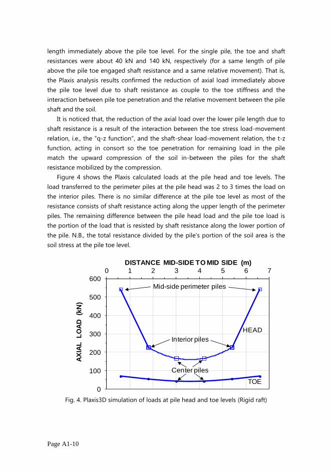
Figure 3 shows the distribution of soil and pile movements and axial pile load for
an imposed 40-mm downward movement of the pile raft (rigid cap). The average pile
compression is small, a few millimetre, only. The analysis showed that the interior
piles experienced no or minimal relative shaft-to-soil movement and, thus, had
minimal shaft resistance until about 2 m above the pile toe level. The mid-side
perimeter piles exposed to the outside of the group had larger relative movement
and more shaft resistance than the interior piles.
For reference, the figure also shows the load distribution for the single pile. The
distribution starts at the same 20-mm pile toe movement relative to the soil as for
the corner pile at the 40-mm pile head movement.
For the interior, mid-side and corner piles, the relative pile toe movement, i.e.,
penetration into the soil were about 7, 14, and 20 mm, respectively. For the corner
pile, the largest relative movement (20 mm) occurred at the pile toe from where it
reduced upward: at 10, 8, and 4 m depths, it was about 15, 12, and 8 mm,
respectively. In contrast, the relative movement between the single pile and the soil
was the smallest at the pile toe and increased upward. From 20 mm at the pile toe, it
increased to about 24 mm at the pile head. This means that a comparison between
the corner pile and the single pile would not quite be apple-to-apple.
0
100
200
300
400
500
600
700
800
0 5 10 15 20 25 30 35 40
LO
AD
(kN
)
MOVEMENT (mm)
Shaft
Head
Toe
Compression
ρ = 2,000 kg/m3
GW at 0.5 m, hydrostatic
ß = 0.37 at δ = 6 mmand = 0.41 at δ = 15 mmrt = 800 kPa at δ = 30mm
t-z = Vander Veen, b = 0.04 q-z = Gwizdala, θ = 0.80

Page A1-9
Fig. 3. Plaxis3D simulation of distribution of soil and pile movements
and axial load for a piled foundation supported on 36 piles.
The analysis shows that the 40-mm imposed downward raft movement is
produced by a 15,590-kN total load (summed up from the load applied to the
individual piles), which corresponds to a 433-kN average load/pile. However, the
loads acting at the head of the perimeter piles ranged from 717 kN for the corner
piles through 167 kN for the center piles. The average load on the interior piles was
about 200 kN.
The average stress is 300 or 380 kPa, respectively, depending on whether the raft
size should be taken as 7.2 m or 6.4 m square (i.e., six times the square of average
distance from pile center to center per pile or the side of the circumscribed square).
A hypothetical totally flexible raft would enable all piles to be loaded equally,
which would show a range of raft settlement with the center pile being the largest.
An actual raft can be considered to be somewhat flexible in response to an applied
load and show more deflection at the center of the raft than at the sides and corners.
The piles at the perimeter center would still take on the larger portion of the load
due to their being affected by shaft resistance. The results of the analysis assuming
the rigid raft are considered representative for an actual piled raft.
The about 7-mm toe penetration of the center piles for the about 165-kN pile
head load resulted in a 40-kN toe resistance and a 125 kN shaft resistance over a 2 m
0
2
4
6
8
10
12
14
16
18
20
0 10 20 30 40 50
DE
PT
H (m
)
Soil at Center Piles
0
2
4
6
8
10
12
14
16
18
20
0 200 400 600 800 1,000
DE
PT
H (m
)
AXIAL LOAD IN PILES (kN)
Center Piles
Soil at Mid-side Piles
Mid-sidePiles
Pile Toe
1 2 3 4 5 6
F
E
A
B
C
D
Soil at Corner Piles
CornerPiles
SOIL AND PILE MOVEMENTS (mm)
SinglePile
Load for 20 mm toe penetration (corner pile and
single pile)
Pile Movements
Perimeter
Piles
IntermediatePiles
Soil at Intermediate
Piles
Page A1-10
length immediately above the pile toe level. For the single pile, the toe and shaft
resistances were about 40 kN and 140 kN, respectively (for a same length of pile
above the pile toe engaged shaft resistance and a same relative movement). That is,
the Plaxis analysis results confirmed the reduction of axial load immediately above
the pile toe level due to shaft resistance as couple to the toe stiffness and the
interaction between pile toe penetration and the relative movement between the pile
shaft and the soil.
It is noticed that, the reduction of the axial load over the lower pile length due to
shaft resistance is a result of the interaction between the toe stress load-movement
relation, i.e., the "q-z function", and the shaft-shear load-movement relation, the t-z
function, acting in consort so the toe penetration for remaining load in the pile
match the upward compression of the soil in-between the piles for the shaft
resistance mobilized by the compression.
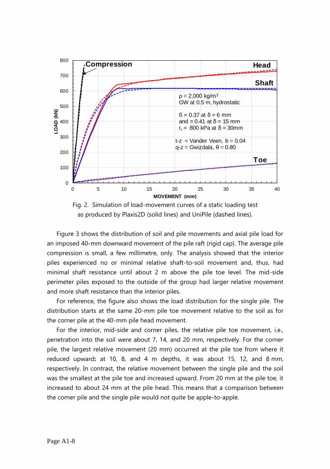
Figure 4 shows the Plaxis calculated loads at the pile head and toe levels. The
load transferred to the perimeter piles at the pile head was 2 to 3 times the load on
the interior piles. There is no similar difference at the pile toe level as most of the
resistance consists of shaft resistance acting along the upper length of the perimeter
piles. The remaining difference between the pile head load and the pile toe load is
the portion of the load that is resisted by shaft resistance along the lower portion of
the pile. N.B., the total resistance divided by the pile's portion of the soil area is the
soil stress at the pile toe level.
Fig. 4. Plaxis3D simulation of loads at pile head and toe levels (Rigid raft)
0
100
200
300
400
500
600
0 1 2 3 4 5 6 7
AX
IAL
L
OA
D
(kN
)
DISTANCE MID-SIDE TO MID SIDE (m)
HEAD
TOE
Interior piles
Mid-side perimeter piles
Center piles
Page A1-11
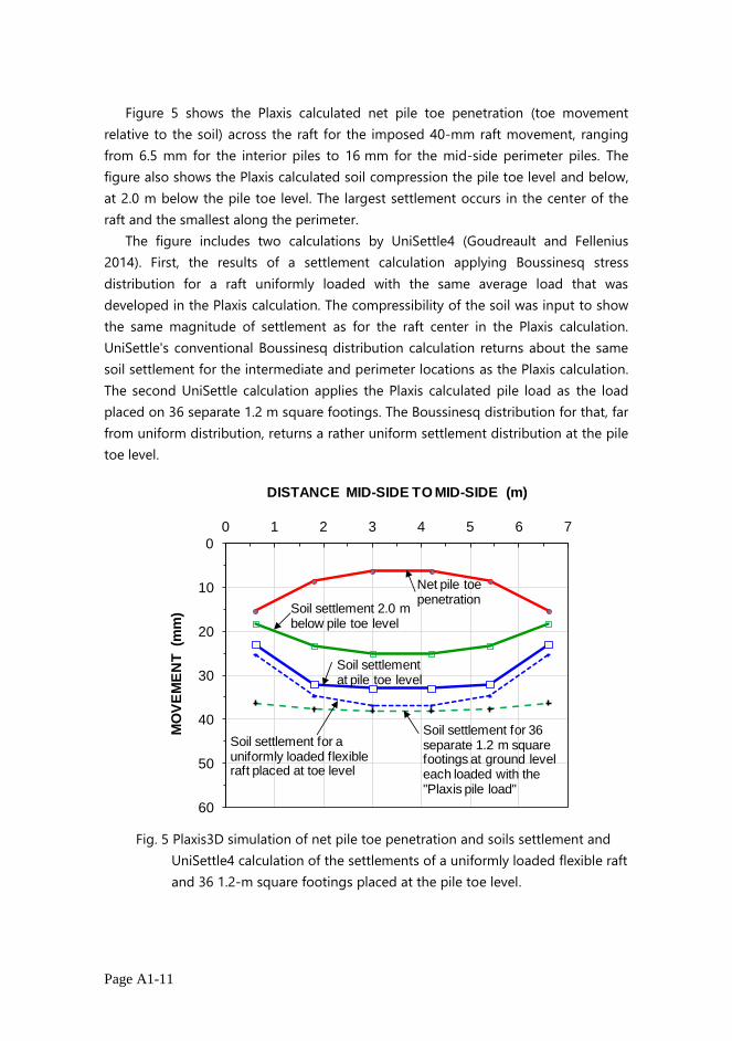
Figure 5 shows the Plaxis calculated net pile toe penetration (toe movement
relative to the soil) across the raft for the imposed 40-mm raft movement, ranging
from 6.5 mm for the interior piles to 16 mm for the mid-side perimeter piles. The
figure also shows the Plaxis calculated soil compression the pile toe level and below,
at 2.0 m below the pile toe level. The largest settlement occurs in the center of the
raft and the smallest along the perimeter.
The figure includes two calculations by UniSettle4 (Goudreault and Fellenius
2014). First, the results of a settlement calculation applying Boussinesq stress
distribution for a raft uniformly loaded with the same average load that was
developed in the Plaxis calculation. The compressibility of the soil was input to show
the same magnitude of settlement as for the raft center in the Plaxis calculation.
UniSettle's conventional Boussinesq distribution calculation returns about the same
soil settlement for the intermediate and perimeter locations as the Plaxis calculation.
The second UniSettle calculation applies the Plaxis calculated pile load as the load
placed on 36 separate 1.2 m square footings. The Boussinesq distribution for that, far
from uniform distribution, returns a rather uniform settlement distribution at the pile
toe level.
Fig. 5 Plaxis3D simulation of net pile toe penetration and soils settlement and
UniSettle4 calculation of the settlements of a uniformly loaded flexible raft
and 36 1.2-m square footings placed at the pile toe level.
0
10
20
30
40
50
60
0 1 2 3 4 5 6 7
DISTANCE MID-SIDE TO MID-SIDE (m)
Soil settlement at pile toe level
MO
VE
ME
NT
(m
m)
Net pile toe penetration
Soil settlement for a uniformly loaded flexible raft placed at toe level
Soil settlement for 36 separate 1.2 m square footings at ground level each loaded with the "Plaxis pile load"
Soil settlement 2.0 m below pile toe level

Page A1-12
APPLYING THE PRINCIPLES TO DESIGN OF WIDE PILED FOUNDATIONS
The numerical analysis does not include the numerous practical aspects that pertain
to piled foundations, such as effect of pile type and construction method, residual
load, sequence of pile construction, variation of pile length, variation of load applied
to various areas across the raft, effect of bending, etc. A design will need to consider
these by applying engineering judgment based on past good practice. Most designs
do not require sophisticated calculations as long as the design is based on methods
that reflect correct pile and soil response in terms of resistance and settlement.
The response of a piled foundation to applied load depends primarily on the
specifics of the foundation, i.e., if it is a single pile or a small group of piles
supporting a column load or a narrow strip of piles supporting a wall, or a wide piled
foundation supporting a tank or a building floor. In addition, the foundation analysis
must include the potential effect of adjacent foundations, future fills and excavations,
and, in particular, general subsidence affecting the site settlement and pile
downdrag.
The design analysis of piled foundation on a single pile or a narrow group of piles
involves determining, per the unified analysis method, the load transfer response of
the piles for the short and long term conditions which entails calculating the axial
compression of the pile(s), the location of the neutral plane, the settlement at the
neutral plane, the pier compression, and the short- and long-term load-transfer pile
toe movement. As detailed in the following, the analysis of a wide pile group is a bit
more complex. It can be separated into three components or steps of calculating
movement and settlement The final settlement of the foundation is the sum of the
three components.
Wide-raft first step
The first step is to determine the axial compression part of the load-transfer
response, which can be assumed similar to a pier with the same envelop as the pile
group for the applied load acting over the full height of the pier and composed of a
material with the combined stiffness of piles and soil.
Wide-raft second step
The second step is to address is the pile-toe penetration, which follows the toe load-
movement response, the q-z function. The toe response is correlated to the stiffness
of the soil immediately above the pile toe level. That analysis makes use of the shaft-
shear movement, the t-z function of the soil above the pile toe level, acting along a
fictitious pile, a soil-pile. The soil-pile has a cross section area that, theoretically, is
equal to the soil portion assigned to each pile minus the area of the actual pile.
However, the area of the soil pile that is affected by shaft resistance is the

Page A1-13
circumferential area of the actual pile. The easiest calculation is by assuming the soil
pile to have the same diameter, area (A), and circumference as the actual pile, but an
E-modulus equal to that of a pile composed of soil scaled to the ratio between the
soil area portion and the pile area. The soil-pile is a pile with no toe resistance. It is
then a simple thing to simulate the soil-pile response to a load applied to its "head"
This represents the upward movement (compression) of the soil in-between the piles,
which is the same as the downward movement, the penetration, of the pile toe. This
movement equivalence is the key to the design analysis.
Figure 6 shows the Plaxis-calculated pile-toe load-movement curve ("Toe
Resistance") and the UniPile-calculated shaft resistance as a function of movement
over the length of pile above the pile toe. The latter curve is calculated as the upward
movement (compression) of the soil in-between the piles, i.e., the soil pile. The figure
also includes the length of pile with shaft resistance above the pile toe. The curve
named "Pile Load" is the sum of the toe curve and the shaft resistance curve at equal
movements.
Fig. 6 Interaction between toe resistance and shaft resistance above the pile toe
The UniPile calculation employed the same unit shaft resistance (beta-coefficient
and target movement) as used for the fit to the Plaxis simulation of the static loading
test (Figure 2). The E-modulus of the pile was input as 200 MPa scaled up from that
used in the Plaxis input by a factor of 10 according to the soil vs. pile area (inverse of
the area ratio). This resulted in an about 2.0 m long pile length with a shaft
resistance, amounting to about 130 kN for an about 7-mm pile-toe load-movement.
Adding the pile toe resistance (40 kN) for the same movement gave a 170-kN pile
head load, that is, about equal to the Plaxis-determined length of pile affected, pile
head load, and toe load on the interior piles.
0.0
1.0
2.0
3.0
4.0
5.0
6.0
0
50
100
150
200
250
300
0 2 4 6 8 10 12 14 16 18 20
LE
NG
TH
AB
OV
E T
OE
LE
VE
L (
m)
LO
AD
(k
N)
MOVEMENT (mm)
Shaft Resistance above pile toe
Pile Load
Toe Resistance
Center pile
Intermediate pile
Pile length with shaft resistance
(above the pile toe)

Page A1-14
The figure shows the results of the same calculation for the intermediate pile and
it, too, agrees well with the Plaxis results. Because of the small shaft resistance along
the interior piles, the load-transfer movements for the interior piles is larger than
those of the single pile for the same pile-head load. The load-transfer movement of
an interior pile in a wide piled foundation depends directly on the pertinent pile q-z
relation. The stiffer the soil at the pile toe level, the smaller the penetration. However,
the penetration is the same as the upward compression of the soil, which is governed
by the shaft resistance of the soil immediately above the pile toe. If the shaft
resistance is soft or loose as opposed to stiff or dense, then, the soil upward
movement will be larger, which will result in a larger toe penetration, which, in turn, is
controlled by the pile toe stiffness. For an actual case, when the t-z and q-z relations
are known, the load transfer due to the load applied to the interior piles can be
determined.
For reasons of separation of curves, the Plaxis case employs a somewhat
unrealistic toe response. Figure 7 shows results of a simulated static loading test on
the same 400 mm, 15 long pile installed in a similar soil, but where an about five
times larger toe stiffness is input than that for simulating the pile test shown in
Figure 2. The pile is a part of a large number of piles installed in a wide group. The
structure imposes a 500-kN average load per pile. What factor of safety that load
represents is uninteresting because the question of the 500-kN sustained load being
acceptable or not rests with the settlement imposed on the foundation in relation to
the settlement the supported structure can tolerate (with some margin). Some may
expect that the load-transfer for the load will be very small as the load-moment
graphs suggests that the 500-kN load would be carried by shaft resistance. However,
as the previous discussion has shown, the interior piles will have minimal shaft
resistance and the portion of the load reaching the pile toe will be considerable.
Fig. 7. UniPile simulation of load-movement curves of a static loading test.
0
500
1,000
1,500
0 10 20 30 40
LO
AD
(k
N)
MOVEMENT (mm)
Toe
Shaft
Head
Compression

Page A1-15
The design procedure requires same input as regularly is used to determine the
response of a single pile or narrow pile group, i.e., the pile toe and pile shaft load-
movement responses, as expressed by the q-z and t-z functions, as well as, of course,
the soil profile. First, in static analysis, using UniPile, or the more sophisticated Plaxis
program, the toe curve of the actual pile is determined. The analysis is then changed
to address a soil-pile, which simply means changing the pile material E-modulus
stiffness to that of the soil, scaled up to represent the ratio of soil area to pile area.
The so-adjusted input is applied to calculating the shaft resistance and its associated
movement of the soil-pile for a series of assumed pile lengths above the pile toe and,
for each, the corresponding movements of the soil-pile "head". The latter represents
the upward movement of the soil in-between the piles and it matches the pile toe
movement for a load equal to the applied load minus the shaft resistance.
Figure 8 shows the calculated pile-toe curve versus pile toe movement, and the
shaft resistance along the series of pile lengths above the pile toe and the respective
pile length versus the upward soil-pile movement. The intersection between the shaft
and toe resistance curves determines the load transfer movement for the applied
load. and toe resistances and the length of the pile above the pile toe where axial
load is shed to the soil as shaft resistance.
Fig. 8. Procedure for determining the load-transfer movement of interior piles.
0.0
3.0
6.0
9.0
12.0
15.0
0
100
200
300
400
500
0 2 4 6 8 10 12 14 16 18 20
LE
NG
TH
AB
OV
E T
OE
LE
VE
L (m
)
LO
AD
(k
N)
MOVEMENT (mm)
Average sustained load on interior piles
Shaft resistance above the pile toe
Toe Resistance
Pile length above the pile toe with shaft resistance
Pile-toe load-transfer movement for the
sustained load

Page A1-16
The analysis requires a judgment decision with regard to what movement to
report as the soil-pile "head" movement for the soil-pile length considered. For
Figure 8, I selected to use the values that were coupled to a 1-mm soil-pile "toe"
movement.
As made clear by the Plaxis analysis, the sustained load on the interior piles may
be smaller than the average load, because of the relatively rigid raft can transfer
some load to the perimeter piles . which are stiffer due to the shaft resistance. Thus, a
pile in the center of a raft would have a sustained load, say 300 kN. Then, shifting the
shaft resistance curve in Figure 8 downward so as to start at 300 kN shows that the
load transfer toe-movement would be about 7 mm, instead. The more able the raft is
to transfer load to the perimeter, the smaller the differential settlement due to load-
transfer will be.
By installing the perimeter piles shorter than the interior piles, the difference in
sustained load between the interior and perimeter piles and bending effect on the
raft can be reduced. However, if long-term condition include subsidence of the
ground surrounding the foundation, then, the perimeter piles would lose the ability
to carry load and, perhaps, start pulling at the raft, which will increase the load on the
center piles. To offset that effect, the perimeter piles may have to be installed longer
than the interior pile. Of course, such short-term and long-term conditions are at
odds. For every foundation design, therefore, the geotechnical and structural
designers need to confer and discuss alternatives. This should not be thought of a
making the unified design analysis unsuitable, on the contrary. The unified design
invites adjusting a design consideration to reality using undistorted loads and
movements and, it therefore improves safety and assured functionality. N.B.,
completing a design based on a capacity by some definition and a factor of safety (or
resistance factor) is little more than closing one's mind and walking away hoping all
will turn to the best.
Wide raft third step
Third step is determining the pile long-term settlement. In contrast to single piles
and narrow pile groups, the interior piles in a wide group are not affected by
settlement due to general subsidence, i.e., downdrag. However, all piles in a wide
group are very much affected by the settlement caused by compression of the soil
below the pile toe level due to the load supported by the raft. This settlement is
easily calculated by analogy to an equivalent raft placed at the pile toe level. It must
include the effect of adjacent foundation, excavation, fills, etc. The following example
of an actual project includes all three steps.

Page A1-17
EXAMPLE
The principles outlined in this paper were recently applied to the design of a Tower
Project in Santa Cruz, Bolivia, involving two 35-storey towers and several smaller
buildings as shown in Figure 9. The total number of individual piled-foundation units
is about 100.
Fig. 9 Foundation plan.
The soil profile at the site is shown in Figure 10 comprising SPT N-indices
diagram and CPTU sounding diagrams. The aspects pertaining to this paper is that
the pile lengths were determined from calculations of load-distribution and
settlement (static loading tests were carried out) and the settlement of each piled
foundation was assessed with respect to its own loading plus the overlapping
stresses from the many adjacent piled foundations. The construction was to include
an excavation and the unloading due to the excavation has, of course, been included
in the analyses. The calculations of the response of the individual piles and pile
groups were made according to the here presented principles and using the UniPile
software (Goudreault and Fellenius 2011). The settlement calculations used the
UniSettle software (Goudreault and Fellenius 2014).
Conclusions
Settlement of single piles and narrow groups is governed by the load-transfer (pile
shortening and pile toe movement) and soil settlement at the neutral plane. The
compression of the soil below the pile toe level is minimal for a single pile or a
narrow (small) pile group.
0
10
20
30
40
50
60
0 10 20 30 40 50 60 70 80 90 100 110 120 130
NO
RT
H-S
OU
TH
(m
)
EAST-WEST (m)
WEST TOWER EAST TOWER
Narrow Group
Wide Group
Wide Group

Page A1-18
Fig. 8 Pile depths and soil profile
(Data courtesy of Incotec Ingenieria y Construccion, Santa Cruz, Bolivia)
The Plaxis analysis results show that in loading a rigid raft, the load is transferred
essentially unaffected by shaft resistance until a short distance above the pile toe
level.
Interior piles will not be affected by drag forces or downdrag. However, the
perimeter piles will.
The pile toe penetration develops in an interactive process between the toe
stiffness (the q-z relation) and the soil stiffness above the pile toe. The pile toe
penetration is equal to the compression of the soil at the pile toe being pushed
upward.
The soil upward process can be modeled in a load-movement analysis with
representative soil input, treating the soil as a gradually loaded soil-pile in a t-z
analysis and applying the same circumference as the actual pile but scaling up the
soil-pile stiffness in relation to the area ratio of the pile group. The paper presents a
graphic solution to the resulting pile toe penetration and load-transfer movement of
the wide pile group.
The primary result of the numerical analysis is, first, the confirmation that the
interior piles experience no or only little relative movement between the shaft and
the soil and, therefore, also minimal shaft resistance until the zone near the pile toe
where the pile toe is pushed into the soil—or, where, conversely considered, the soil

Page A1-19
is pushed upward in-between the piles. The second primary result is that the
perimeter piles do experience larger relative movement and shaft resistance along
the full length of the piles.
In contrast to the interior piles, perimeter piles experience shaft resistance which
will make them take on larger loads than the interior piles. The perimeter pile loads
can be reduced by designing these pile shorter than the interior piles. However, if the
site is affected by general subsidence resulting in downdrag, the perimeter piles may
instead have to be made longer than the interior piles.
In any design of piled foundations, it is necessary to be able to determine the
load distribution during the loading of the pile, in particular, the pile toe load-
movement response. This can be achieved by experienced engineering judgement,
but more often than not, full-scale static loading tests are required to reduce the
uncertainty of the project. No test should be carried out without establishing the pile
toe response by instrumentation, preferably, combined with a bidirectional test,
where the load application is close to the pile toe so the frequently ambiguous
results of instrumentation are allayed.
References
Fellenius, B.H., 2016. The unified design of piled foundations. The Sven Hansbo
Lecture. Geotechnics for Sustainable Infrastructure Development – Geotec Hanoi
2016, edited by Phung Duc Long, Hanoi, November 23-25, pp. 3-28.
Fellenius, B.H., 2017. Basics of foundation design–a textbook. Pile Buck International,
Inc., Vero Beach, FL, Electronic Edition, www.Fellenius.net, 464 p.
Goudreault, P.A. and Fellenius, B.H., 2011. UniSettle Version 4 tutorial with
background and analysis examples. UniSoft Geotechnical Solutions Ltd.
[www.UniSoftLtd.com]. 85 p.
Goudreault, P.A. and Fellenius, B.H., 2014. UniPile Version 5, User and Examples
Manual. UniSoft Geotechnical Solutions Ltd. [www.UniSoftLtd.com]. 120 p.
Okabe, T., 1977. Large negative friction and friction-free piles methods. 9th ICSMFE,
Tokyo, July 11-15, Vol. 1, pp. 679-682.