design of shear walls in response spectrum method and to ... · design of shear walls in response...
TRANSCRIPT
ISSN: 2455-2631 © March 2018 IJSDR | Volume 3, Issue 3
IJSDR1803015 International Journal of Scientific Development and Research (IJSDR) www.ijsdr.org 65
Design of shear walls in response spectrum method
and to study the effect of stiffness in high rise
buildings by using Etabs
1Channamallu Komali,
2Venkata Krishna Amaraneni
1M-Tech Student,
2Assistant Professor,
1Civil Engineering Department,
1Chalapathi Institute of Technology, Mothdaka, Guntur,
Abstract— Besides, food and clothing, shelter is a basic human need. India has been successful in meeting the food and
clothing requirements of its vast population; however the problem of providing shelter of all is defying solutions. Hence in
order to overcome this problem construction process should be quick, tall and effective to accommodate huge population
in a given area. So we have chosen this topic of “DESIGN OF SHEAR WALLS IN RESPONSE SPECTRUM METHOD
BY USING ETABS-2013”. “Design of shear walls” is the challenging task. Shear walls have a peculiar behavior towards
various types of loads. Calculation of lateral loads, shear force, storey shear, bending moment and displacements is a topic
of interest. We are going to check the building behaviour. We are verifying and designing this structure using extended
three dimensional analysis of buildings by (ETABS) software.
Index Terms— Shear walls, High rise buildings, Stiffness, Response Spectrum Method (key words)
________________________________________________________________________________________________________
I. INTRODUCTION
Shear walls are vertical elements of the horizontal force resisting system. Shear walls are constructed to counter the effects of
lateral load acting on a structure. In residential construction, shear walls are straight external walls that typically form a box
which provides all of the lateral support for the building. When shear walls are designed and constructed properly, and they will
have the strength and stiffness to resist the horizontal forces.
In building construction, a rigid vertical diaphragm capable of transferring lateral forces from exterior walls, floors, and roofs to
the ground foundation in a direction parallel to their planes. Examples are the reinforced-concrete wall or vertical truss. Lateral
forces caused by wind, earthquake, and uneven settlement loads, in addition to the weight of structure and occupants; create
powerful twisting (torsion) forces. These forces can literally tear (shear) a building apart. Reinforcing a frame by attaching or
placing a rigid wall inside it maintains the shape of the frame and prevents rotation at the joints. Shear walls are especially
important in high-rise buildings subjected to lateral wind and seismic forces.
In the last two decades, shear walls became an important part of mid and high-rise residential buildings. As part of an earthquake
resistant building design, these walls are placed in building plans reducing lateral displacements under earthquake loads. So
shear-wall frame structures are obtained.
Shear wall buildings are usually regular in plan and in elevation. However, in some buildings, lower floors are used for
commercial purposes and the buildings are characterized with larger plan dimensions at those floors. In other cases, there are
setbacks at higher floor levels. Shear wall buildings are commonly used for residential purposes and can house from 100 to 500
inhabitants per building.
II. SCOPE OF THE WORK
The aim of the shear wall is to investigate the different ways in which the tall structures can be stabilized against the effects of
strong horizontal wind loading and seismic loading. Some other reasons why we use shear walls are tall structures can be
constructed which reduces the area used and we can accommodate a large population in that particular area. Other objective is to
construct a cost effective structure in less period of time. This study helps in the investigation of strength and ductility of walls.
The scope is to analyze the constructed shear wall that is to be constructed. Firstly the model is implemented into known
computer software and then it is analyzed based on the investigation of strength and ductility. The strength of shear walls tested
are compared with the calculated strengths based on design codes

ISSN: 2455-2631 © March 2018 IJSDR | Volume 3, Issue 3
IJSDR1803015 International Journal of Scientific Development and Research (IJSDR) www.ijsdr.org 66
III. LITERATURE REVIEW
Development of shear wall system for construction has advanced dramatically over the past few years. Shear wall systems were
initially developed to reduce damage due to earth quakes labour requirements, increase strength of the building, shorten
construction time reduce cost increase quality of life.
U.H. Varyani described about shear walled buildings under horizontal loads. Considering in his design “Reinforced concrete
framed buildings are adequate for resisting both the vertical and the horizontal loads acting on shear walls of a building”. In this
2nd edition 2002 of “Design of structures”. He gave rigidity of shear wall, torsional rigidity and shear center of a building in a
detailed description.
S.K. Duggal on his profound interest on structures gave a detailed description about reinforced concrete buildings in his book
“ Earth quake resistant design of structures “describing a wall in a building which resist lateral loads originating from wind or
earthquakes are known as shear walls”. He considered flexural strength in the wall to be dominant force based on which design
of structure to be carried out in tall shear walls. He described in detail about various types of shear walls with their load bearing
capacities as per code requirements.
Mr A.P. Jadhav Associate Professor Rajarambapu Institute of technology rajaramnagar, Islampur has given a detailed report on
the form work used for the construction of shear walls. Mr.A.P.Jadhav highlighted the importance of quickness in construction
and the need for earthquake resistant building for better sustainability of life.
A report on effects of openings in shear walls on seismic response of structure by sharminriza chowdhary, department of civil
engineering dhake-1208, Bangladesh mostly focused on the design of shear walls with openings on seismic response using E-
Tabs, i.e extended three dimensional analysis of buildings. This report gives a detailed explanation of how ETABS can be
effectively used to design shear walls.
IV. DESIGN OF SHEAR WALLS
Shear walls construction is an economical method of bracing buildings to limit damage. For good performance of well-designed
shear walls, the shear wall structures should be designed for greater strength against lateral loads than ductile reinforced concrete
frames with similar characteristics; shear walls are inherently less ductile and perhaps the dominant mode of failure is shear. With
low design stress limits in shear walls, deflection due to shear walls is small. However, exceptions to the excellent performances of
shear walls occur when the height-to-length ratio becomes great enough to make overturning a problem and when there are
excessive openings in shear walls. Also, if the soil beneath its footing is relatively soft, the entire shear wall may rotate, causing
localized damage around the wall. Following are the design steps of cantilever shear walls.
General Requirements
(a) The thickness of the shear wall should not be less than 150mm to avoid unusually thin sections. Very thin sections are
susceptible to lateral instability in zones where inelastic cyclic loading may have to be sustained.
(b) The effective flange width for the flanged wall section from the face of web should be taken as least of
* Half the distance to an adjacent shear wall web, and
* One-tenth of total wall height.
(c) The minimum reinforcement in the longitudinal and transverse directions in the plan of the wall should be taken as 0.0025
times the gross area in each direction and distributed uniformly across the cross-section of wall. This helps in controlling
the width of inclined cracks that are caused due to shear.
(d) If the factored shear stress in the wall exceeds 0.25√fck or if the wall thickness exceeds 200mm, the reinforcement
should be provide in two curtains, each having bars running in both the longitudinal and transverse directions in the plane
of the wall. The use of reinforcement in two curtains reduces fragmentation and premature deterioration of the concrete
under cyclic loading.
Materials and Properties:
Type of frame: Special RC moment resisting frame fixed at the base
Seismic zone: II
Number of storey: Thirteen
Floor height: 3.0 m
Depth of Slab: 150 mm
Size of beam: (200 × 600) mm
Size of column: (450 × 450) mm
Spacing between frames: 5 m along x and 5m along y- directions
Live load on floor: 2 KN/m2
Floor finish: 1.5 KN/m2
Wall load: 10 KN/m

ISSN: 2455-2631 © March 2018 IJSDR | Volume 3, Issue 3
IJSDR1803015 International Journal of Scientific Development and Research (IJSDR) www.ijsdr.org 67
Materials: M 30 concrete, Fe 500 steel Material
Thickness of wall: 200 mm
Thickness of shear wall: 200mm
Density of concrete: 25 KN/m3
Density of infill: 20 KN/m3
Type of soil: Hard
Response spectra: As per IS 1893(Part-1):2002
Damping of structure: 3 percent.
Design Load Combinations
The design loading combinations are the various combinations of the pre- scribed response cases for which the structure is
to be checked/designed. The program creates a number of default design load combinations for a concrete frame design. Users
can add their own design load combinations as well as modify or delete the program default design load combinations. An
unlimited number of design load combinations can be specified.
To define a design load combination, simply specify one or more response cases, each with its own scale factor. The scale
factors are applied to the forces and moments from the analysis cases to form the factored design forces and moments for each
design load combination. There is one exception to the preceding for spectral analysis model combinations, any correspondence
between the signs of the moments and axial loads is lost. The program uses eight design load combinations for each such
loading combination specified, reversing the sign of axial loads and moments in major and minor directions.
Design Strength
The design strengths for concrete and steel are obtained by dividing the characteristic strength of the material by a partial
factor of safety, γ. The values of γ used in the program are as follows:
Partial safety factor for steel, γ = 1.15, and (IS456 36.4.2.1)s
Partial safety factor for concrete, γ= 1.5. (IS456 36.4.2.1)c
These factors are already incorporated in the design equations and tables in the code. Although not recommended, the program
allows the defaults to be over- written. If the defaults are overwritten, the program uses the revised values consistently by
modifying the code mandated equations in every relevant place.
Boundary Conditions
There are the portions along the wall edges and may have the same or greater thickness than the wall web. These are
provided throughout the height with special confining reinforcement. Wall sections having stiff and well confined boundary
elements develop substantial flexural strength, are less susceptible to lateral buckling and have better shear strength and
ductility in comparison to plane rectangular walls not having stiff and well-confined boundary elements.
(a) During a severe earthquake, the ends of a wall are subjected to high compressive and tensile stresses. Hence, the
concrete needs to be well confined so as to sustain the load reversals without a large deterioration in strength.
Thus, the boundary elements are provided along the vertical boundaries of walls, when the extreme fibre
compressive stress in the wall due to factored gravity load plus factor earthquake force exceeds 0.2fck. The
boundary element may be discontinued where the calculated compressive stress becomes less than 0.15fck.
(b) The boundary element is assumed to be effective in resisting the design moment due to earthquake induced
forces, along with the web of the wall. The boundary element should have an adequate axial load carrying
capacity so as to carry an axial compression equal to the sum of the factored gravity load plus compressive load
due to seismic load.
(c) Moderate axial compression results in higher moment capacity of the wall. Hence, the beneficial effect of axial
compression by gravity loads should not be fully relied upon in a design, due to the possible reduction in its
magnitude by vertical acceleration. When gravity loads add to the strength of the wall, a load factor of 0.8 may
be taken
(d) The percentage of vertical reinforcement in boundary elements should range between 0.8 and 6 percent.
(e) During a severe earthquake, boundary elements may be subjected to stress reversals. Hence, they have to be
confined adequately to sustain the cyclic loading without a large degradation in strength. Therefore, these should
be provided throughout their height.
(f) Boundary elements need not be provided if the entire wall section is provided with special confining
reinforcement.
V. DESIGN OF G+13 SHEAR WALL BUILDING USING E-TABS
ETABS is sophisticated software for analysis and design program developed specifically for buildings systems. ETABS
version-2013.1.5 features an in intuitive and powerful graphical interface coupled with unmatched modelling, analytical, and

ISSN: 2455-2631 © March 2018 IJSDR | Volume 3, Issue 3
IJSDR1803015 International Journal of Scientific Development and Research (IJSDR) www.ijsdr.org 68
design procedures, all integrated using common database. Although quick and easy for simple structures, ETABS can also
handle the largest and most complex building models, including a wide range of nonlinear behaviors, making it the tool of
choice for structural engineers in the building industry.
Modelling
Firstly click on the ETABS icon .A window appears which shows a different tip every time you open the software. Change
the units at the right bottom to KN-m or any other as per your convenience. Click on file option to create a new file or to open
an already existing file. As we are creating a new file, we click on default.edb.
A new window appears which has Building plan grid system and Story data. In grid dimensions we can either use
uniform spacing or we can customize the grid spacing. We have to provide no of lines in x and y directions as per the
columns and beams used in the plan.
In the story dimensions, we have simple story data and custom story data. In simple story data, use the defaults or
specify values for the number of stories, typical story height, and bottom story height.
After providing the entire data click on grid only in structural objects and then click on ok.
Now the screen is divided into two equal halves in which one is plan view and the other is 3-D view of the provided data.
After the entire grid data and story data is provided, then we have to define the properties of the material that is used.
To define a material property, select define=>material properties. This makes us to either add new material, modify or
delete an existing material. Click on add new material to create a new material with required properties.
Firstly provide a name(say M20,M30 etc) and then provide the other properties of the material such as mass per unit
volume, weight per unit volume, elastic modulus, Poisson’s ratio. The other design properties that are to be provided are
characteristic compressive strength and yield strength values. You have other options such as change in display colour,
type of material which is always isotropic. After the entire data is provided click on ok.
The next step is to create beams and columns. To create a beam or column, first we click on define=>frame sections
command to create a beam or column. In this window we have import and add options further provided with modify or
delete options of already existing properties.
Provide the dimensions of the section as required and change the data according to the section provided. If a beam is to be
provided then select the design type to beam and provide the required dimensions to the cover and if a column is provided
select design type to column and then nominal cover is provided.
To create a column, the above process is repeated again and the only difference is the reinforcement data which is stated
earlier both for beams and columns.
To assign a beam, we can directly click on the icon create lines or region at click. The other way to do it is to click on
Draw menu=>Draw line objects=>Create lines or regions at click command. A window appears which provides properties
of the object in which the property is changed to the beam that we defined earlier. We can click on each grid point or
directly select all at once and the beams are assigned to the grid.
To assign a column, we can click on create columns in region or at clicks or click on Draw menu=>Draw line
objects=>Create columns in region or at clicks. In this the property is changed to the defined column and columns can be
assigned to offsets in x and y directions. Columns are also assigned in the similar way as beams are assigned.
Further we have to provide slabs for which we have to select define menu=>wall sections after which a window appears
with options add new, modify/show section and delete section. Click on add new slab and click on ok. A new window
appears where provide the section name as slab and the material is changed to the already defined one. The other data is
kept as it is. We can change the display colour to our convenience and then click ok.
To assign a slab, directly click on the draw rectangular areas and the other is to click on Draw menu=>Draw area
objects=>draw rectangular areas. The properties of the object are changed to the defined slab and then assigned to the end
points of the grid. The slab can be made visible by a click on Set Building view options on the top and the option object
fill is marked in special effects options.
After the slab is assigned to the structure the next step is to provide the wall for the structure which is the major portion of
the construction as we are providing shear walls. Shear walls are directly provided as that of slab with the help of a special
type of formwork using concrete. There is no role of bricks in this kind of wall. There are some requirements for shear
wall design i.e., the minimum thickness of the shear wall should be 150 millimeter or more.
Now for construction of a wall, firstly click define=>wall/slab/deck sections=>click to add new wall=>name the wall and
the material is selected as M30 and no more brick is used and then click ok without changing any other information.
To assign the wall, click directly on draw walls or create walls at click at the left side of screen or select draw=>draw area
objects=>draw walls or create walls at click and assign the walls at the required places. To make the wall visible, click on
SetBuilding options and the object fill is marked.
Assigning of loads:
After the columns, beams, walls and slabs are assigned now the loads are to be applied to the structure. There are
different load combinations used in this software. For shear walls, lateral loads and seismic loads play a vital role.
To assign any particular load, click Define=>Static load cases. In this window dead load and live load are already
assigned. To assign any other loads change the name of the load in load option, select the load type in type option,
add the self weight multiplier as required. The auto lateral load options provide different code books that are used
across the world. We use IS 1893-2002 code.
ISSN: 2455-2631 © March 2018 IJSDR | Volume 3, Issue 3
IJSDR1803015 International Journal of Scientific Development and Research (IJSDR) www.ijsdr.org 69
After we have defined the loads that are required to be provided for the structure, now the loads are need to be
assigned. For the loads that are acting on beams, select all the beams and then click assign=>frame/line loads
=>distributed=>select the load that is to be to assigned and then click ok.
For slabs and walls, select all the walls and slabs and then click on assign=>shell/area loads=>uniform. Select the
load that is to be assigned and then click ok.
To check whether the loads are assigned or not, click display=>show loads=>select joint/point or frame/line or
shell/area=>select the load that you need to check in load case and then click ok. The load is displayed in the plan
view at the center.
There are several load combinations that can also be designed depending on the requirements by selecting
define=>load combinations and then we can add numerous combinations as per the given code.
The additional loads that are to be defined are seismic and lateral loads for shear wall design. Hence quake and wind
loads are defined in both x and y directions and then they are assigned to the structure.
Analysis:
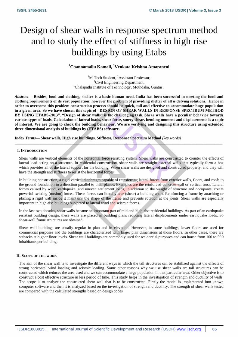
After all the loads are assigned, now click analyze=>run analysis. After the complete structure is analyzed, the
deformed shape of the structure is shown in 3D view. This is due to the loads that are acting on all the sections i.e.,
beams, columns, walls and slabs.
Fig 1- after analysis deflection diagram Fig 2- after analysis moment 3-3 diagram for dead load.
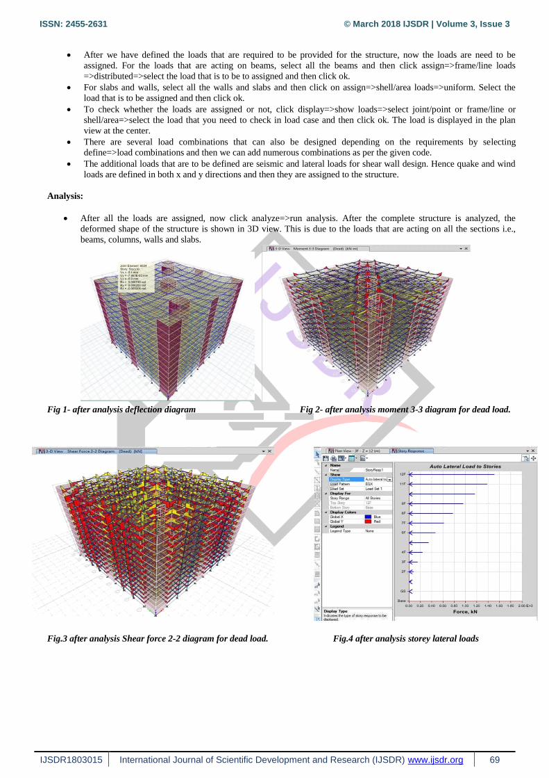
Fig.3 after analysis Shear force 2-2 diagram for dead load. Fig.4 after analysis storey lateral loads
ISSN: 2455-2631 © March 2018 IJSDR | Volume 3, Issue 3
IJSDR1803015 International Journal of Scientific Development and Research (IJSDR) www.ijsdr.org 70
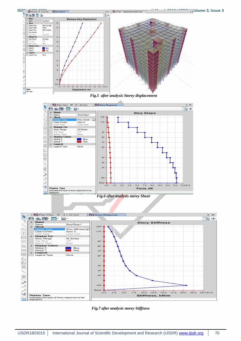
Fig.5 after analysis Storey displacement
Fig.6 after analysis storey Shear
Fig.7 after analysis storey Stiffness

ISSN: 2455-2631 © March 2018 IJSDR | Volume 3, Issue 3
IJSDR1803015 International Journal of Scientific Development and Research (IJSDR) www.ijsdr.org 71
Fig.8 after analysis storey Shear
Design:
Fig.9 designing. Fig.10 after designing.
ISSN: 2455-2631 © March 2018 IJSDR | Volume 3, Issue 3
IJSDR1803015 International Journal of Scientific Development and Research (IJSDR) www.ijsdr.org 72
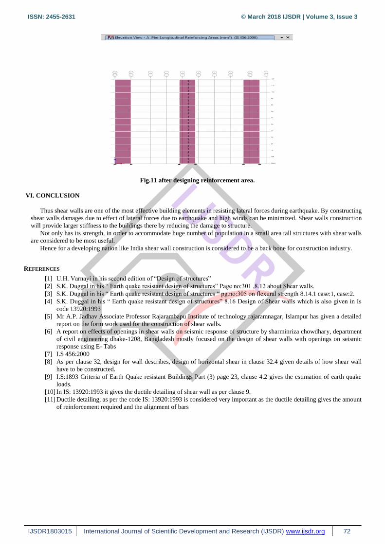
Fig.11 after designing reinforcement area.
VI. CONCLUSION
Thus shear walls are one of the most effective building elements in resisting lateral forces during earthquake. By constructing
shear walls damages due to effect of lateral forces due to earthquake and high winds can be minimized. Shear walls construction
will provide larger stiffness to the buildings there by reducing the damage to structure.
Not only has its strength, in order to accommodate huge number of population in a small area tall structures with shear walls
are considered to be most useful.
Hence for a developing nation like India shear wall construction is considered to be a back bone for construction industry.
REFERENCES
[1] U.H. Varnayi in his second edition of “Design of structures”
[2] S.K. Duggal in his “ Earth quake resistant design of structures” Page no:301 ,8.12 about Shear walls.
[3] S.K. Duggal in his “ Earth quake resistant design of structures “ pg.no:305 on flexural strength 8.14.1 case:1, case:2.
[4] S.K. Duggal in his “ Earth quake resistant design of structures” 8.16 Design of Shear walls which is also given in Is
code 13920:1993
[5] Mr A.P. Jadhav Associate Professor Rajarambapu Institute of technology rajaramnagar, Islampur has given a detailed
report on the form work used for the construction of shear walls.
[6] A report on effects of openings in shear walls on seismic response of structure by sharminriza chowdhary, department
of civil engineering dhake-1208, Bangladesh mostly focused on the design of shear walls with openings on seismic
response using E- Tabs
[7] I.S 456:2000
[8] As per clause 32, design for wall describes, design of horizontal shear in clause 32.4 given details of how shear wall
have to be constructed.
[9] I.S:1893 Criteria of Earth Quake resistant Buildings Part (3) page 23, clause 4.2 gives the estimation of earth quake
loads.
[10] In IS: 13920:1993 it gives the ductile detailing of shear wall as per clause 9.
[11] Ductile detailing, as per the code IS: 13920:1993 is considered very important as the ductile detailing gives the amount
of reinforcement required and the alignment of bars