design of reinforced concrete structures prof. n. dhang...
TRANSCRIPT

Design of Reinforced Concrete Structures
Prof. N. Dhang
Department of Civil Engineering
Indian Institute of Technology, Kharagpur
Lecture - 10
Design of Doubly Reinforced Beam Flexure
Today we shall learn, how to design flanged beams. So, our next lecture design of
flanged beams and again we are considering flexure.
(Refer Slide Time: 01:17)
This is one cross section of a T beam, we have web and clench. This is bw is the width of
the web, Df generally it is depth of the slab and bf is the width of the flange. Here again,
we consider we take effective depth d upto the depth of that level of the tensile steel and
D is the overall depth. So, we have 2 more parameters Df and bf.

(Refer Slide Time: 02:10)
We have one more cross section that is called L beam. L beam you mostly, you will find
L beam near the edge of the building. Because, the other side you do not have slab so,
you are getting only one side you are having the flange. So, bw, Df, bf, d and D these are
the parameters how you can describe the beam.
(Refer Slide Time: 02:36)
Let us, see that what our code says IS 456 2000 what our code says and you will find out
in this clause, clause 23 1 1. A slab which is assumed to act as compression flange of T
beam or L beam shall satisfy 1 I have told please note, I have told that compression

flange because, the flange will not be tensile. Because, the concrete will not take that
tension. So, always it will be compression flange.
The slabs shall be cast integrally, with the web or the web and the slab shall be
effectively bonded together in any other manner, either it is cast at the same time or
where the end slab. That means, beam and slab that 1 integrated may be due to the
reinforcement or some other means, you are doing that 1 that you will get the same that
you say deformation, you will get it for web and slab.
(Refer Slide Time: 03:48)
If the main reinforcement of the slab is parallel to the beam, transverse reinforcement
shall be provided as in figure 3 of IS 456 I shall show you, such reinforcement shall not
be less than 60 percent of the main reinforcement at mid span of the slab. What do you
mean by main reinforcement? That is 1 is called main reinforcement and the other 1 is
called transverse reinforcement. In this case, the main reinforcement is towards the along
the longitudinal beam.

(Refer Slide Time: 04:36)
So, in the transverse detection we have to provide the if this is the slab and you have the
we are looking for the top say 1 beam. So, if you look from this side, I shall get a beam
this is slab and a beam like this. The reinforcement we are providing here, along these
line in the slab. So, this is that figure 3 in IS 456 and we have the reinforcement at down
in other way and anyway it does not matter.
So, I shall show you the main reinforcement of the slab along these line. So, transverse
reinforcement we have to provide this way and that should not be less than 60 percentage
of the main reinforcement. In that case, also we can take the slab as a part of the flange
as a T beam. So, it bends along these line so, it should resist whenever it will bend these
beam the slab should resist. So, we shall get some equivalent length of the flange.

(Refer Slide Time: 06:27)
Typically, what happens actually say a building we are considering a building, we are
taking a building. We have so many compartments let us, say these are the different
compartments. These are the beams we have say columns here, these are the column
positions we do not need the column just for to complete this figure. Let us, say these are
the different columns and these are the slabs when we are talking this beam, what we can
do whenever we are talking this beam, we shall get the cross section in this way.
Now, for design purpose what shall we do, for design purpose shall we take only these
portion? But that is not a good solution as if that we are taking that the this slab, this
beam is cast first then, the slab. But that is not the case, we are casting this beam as well
as a slab at the same time and we can take the flange action of the slab also, we can take
while designing the beam.
So, how far shall we go if we take the beam a T beam or a L beam here we have to
specify, that there is no problem to define these bw; bw width of the web, depth of the
slab or flange depth. We can specify the overall depth D, but what about this bf ? Or for
the edge beam, what about these bf? That we shall find out and we shall call it effective
width of flange.

(Refer Slide Time: 08:58)
So, effective width of flange according to IS 456 for T beams we shall get bf equal to l 0
by 6 plus bw already we have defined w plus 6Df. The depth of flange what is this L0?
L0 is the effective span; L0 is the effective span and that we have to find out from
different cases according to IS 456 we have to find out the L0. For the time being let us,
consider we shall take it say centre to centre, but between 2 supports centre line of 2
supports.
It is possible also, that between to the point of contra flexor that means, the point that
where you are having moment 0 we shall take that point between those we can take so,
least of that we shall take it the effective span. Effective span we shall find out and that
we shall come when, in we shall do the design. Right now, we are not doing the actual
design we are doing the part of it.
But when, we shall do it a design say a slab or beam we shall design that time we have to
take the effective span we have to calculate. And that time I shall tell you in detail, what
could be the effective span for time being let us, take the centre to centre between 2
supports for the time being.

(Refer Slide Time: 10:37)
Now, what about L beam; for L beams it is l0 by 12 plus bw plus 3Df.
(Refer Slide Time: 10:59)
Next 1, we have for isolated beams the effective flange width shall be obtained as for T
beams we take it this formula you will find out in IS 456. We I have taken it from IS 456
only. So, l0 by l0 by b plus 4 plus bw l0 by 6 possibly l0 by 6 what are isolated beams?
Isolated beams is a separate beam we shall consider that means, say we are having only 1
beam saying the slab. We are considering 1 beam, not the 1 different the way I have
given that 1 frame is not a frame structure.

Just you are considering between say 2 walls, we can say that we are having 1 beam the
spread, that 1 we consider as isolated beam.
(Refer Slide Time: 11:50)
And similarly, for L beam 0 5l0 by l0 by 6 plus 4 plus bw.
(Refer Slide Time: 12:01)
Now, let us come to 3 different cases if we take according to the this is 1 case where,
neutral axis within flange. That means, this is your say neutral axis position say and the
whole stress block is within the flange. That could be 1 case how many cases according
to stress block, how many different cases can happen, can occur. So, this is 1 particular

case 1 case when, the whole stress block is within the flange. That mean, the neutral axis
is within the flange that is possible.
(Refer Slide Time: 13:08)
The next case is possible so, you shall come to the formulation again we shall just let me,
tell you first what is the first case, the second case is possible the neutral axis below the
flange, that is possible neutral axis below the flange. But the flange is uniformly stressed;
that means, we are taking these portion flange is uniformly stressed these portion is that
is 0 45 fck; 0.45 fck that is your say flange and then, we can get that uniformly stressed.
(Refer Slide Time: 13:38)

The third 1 possible case 3: when, flange is uniformly this 1 I have given you just let me,
now go back I shall. So, what are that 2 different cases just a minute little bit to elaborate
what I have done here. So, we have 2 portions I think, I can come here what I have done
here.
So, I have done here the whole portion and we are taking that means, when we are
considering the flange is uniformly stressed. In that case, I can take this wave 1 part and
the other part I can take that only flange. So, that means the rectangular portion the wave
only and the flange that I have taken.
(Refer Slide Time: 15:02)
So, that you can get it that yes so, this is that rectangular part which is whatever we have
derived so far. And the other part the portion that flange so, bf minus bw because, I have
already taken this 1 in the web and where, we are getting this the 0 45 fck that your say
rectangular block of the stress block we are taking.

(Refer Slide Time: 15:22)
The third case is possible neutral axis is below the flange and flange is not uniformly
stressed. So, flange is not uniformly stressed it means that means, certain portion here we
shall get I can show you, as if it is like this. So, if this is your stress block. So, you have
flange may come some were here. So, this portion is coming within the flange that is
why you are telling flange is not uniformly stressed.
So, here 3 cases: case number 1 the neutral axis is within the flange, case 2 the neutral
axis in the web, but the flange is uniformly stressed; that means, the flange is throughout
the depth the flange is having stressed 0.45 fck. And third case: flange is not uniformly
stressed; that means certain parabolic portion is also coming in the flange. So, these are 3
different cases you have to consider when, you will design the flanged beam.

(Refer Slide Time: 17:04)
So, let us take 1 by 1 let us do another part let us, see from the strain point of view our
strain in concrete permitted 0.0035 and epsilon s is depending on different steel. We
shall get different strain for Fe 415 we shall take 0.0038. Let us, say 0.004 there is 1
place here where we are stress-strain 0.002. We have strain 0.002 because, above this
0.002 we shall get the stress 0.45 fck. So, this is the level up beyond which that above
this we shall get 0.45 fck.
Our question is that, let us say this is Df what should be the maximum Df possible and
this length that is effective depth d. So, we have d and Df is the depth of flange or the
depth of the slab. So, our question is that what should be the depth of the slab? We can
write down here, Df by d will be equal to how much this1 0.0035 minus 0.002 divided
by 0.004 plus 0.0035 I am taking this 1 whole from this triangle. So, these divided by
this 0.004 plus 0.0035.
So, I can get Df by d equal to 0 2 that means, if we can get that xu by d. We can get X by
d; X by d is that 1 related to neutral axis is from top 5 are divided by effective depth that
we calculate. So, x by d we can calculate either from the moment or from the section we
can get x by d. So, if x by d is less than Df by d then, we can say that it is within the
flange.
It is also possible x by d greater than Df by d, but we have to check that whether we are
getting that 1 that uniformly stressed or not, whether, we are getting uniformly stressed

or not. So, we shall solve few problems, but before that let us, derive that which formula
we should use. So, this Df by d is equal to 0 2 is an important parameter to check
whether, the neutral axis is within the flange or within the web.
(Refer Slide Time: 20:42)
So, case 1: neutral axis is within the flange, we can write down the same rectangular
formula Mu equal to 0.36 fck x by d 1 minus 0.416 x by d times what about the width bd
square here that width will be bf times d square. Why? Because, the T beam we are
considering here and the stress block say somewhere like this T and C. So that means,
somewhere the neutral axis is somewhere here. So, this is your bf it is nothing, but the
rectangular it is nothing, but the same rectangular beam.
Because, that remaining bottom portion we do not do that concrete will not take part in
any tension or anything. So, in other way if we can make it like these also that also that
means, this is void this portion is void because, we are providing the reinforcement here.
So, I can remove that concrete from that portion because, we do not need it. So, we need
only at the top because, this 1 only taking part in the your say binding and compression
also the concrete.
So, I can remove that certain portion, but we do not do it. Because, that for the shuttering
cost or other cost will be more and. So, whatever you are going to achieve to removing if
you say concrete, but your shuttering other things again will cost more. So, that is why if
it is not at all required, we do not go for this type of cases.

Now, Mu equal to 0.36 the same formula only thing change that, instead of having that
just b we are getting that bf. So, from here we can get that x by d we can get it the same
way if we know the Mu, we can find out x by d when, the cross section we can find out
from the expression this is the 0.87 fy Ast that is the tensile force divided by 0.36 fck
times bf; bf is the width of the flange.
So, from here also we can find out that x, x we can find out that means, if that only cross
section is given here moment is given. So, from there we can find out x by d here also we
can find out x by d. In other way, I have to write down x by d equal to 0.87 fy Ast
divided by 0.36 fck bf times d.
(Refer Slide Time: 24:52)
Now, what about case 2? Neutral axis below the flange and Df by d less than 0 2 that
means, flange is uniformly stressed. Draw the figure once more and bw, this is bw and
we have d. So, Mu equal to Mu 1 for rectangular portion which is nothing, but bw times
d plus Mu 2 for slab that means, bf minus bw times Df. So, we are removing this 2
portion.
So, we are doing it separately bw and d this is Df if I take this portion bf minus bw by 2
and similarly, the other 1 also. So, we are taking this 2 rectangular portions. So, we have
to find out the compressive force; the compressive force we shall get it for rectangular
portion we shall get it. And for the other 2 sides the flange portion we shall take it which
is uniformly stressed.

So, you can write down Mu 1 equal to 0.36 fck bw times x times d minus 0.416 x. What
about Mu 2? Mu 2 will be 0.45 fck times bf minus bw, that is the force times Df, this is
the area times the stress 0.45 fck bf minus bw times Df, that is the force times lever arm
d minus Df by 2 d minus Df by 2. So, d and we are taking this portion. So, this your lever
arm. So, Mu will be equal to Mu 1 plus Mu 2 so, this is your case 2.
So, case 1: that simple you say rectangular section case 2 that we have 2 parts: 1
uniformly stressed the flange part and the wave that which is nothing, but the rectangular
portion. Yes next slide this 1 no I am showing this 1 only isn’t it? The case 3 there is
only a small difference, what we do we get the equivalent depth this Df; Df is the depth
of the flange what we do this Df will be replaced by certain equivalent depth of the
flange.
(Refer Slide Time: 30:18)
(( ))
The case 3: neutral axis below the flange and Df by d greater than 0 2 and flange is not
uniformly stressed. So, what we shall do we get yf instead of having Df we get yf; yf will
be equal to 0 15x plus 0 65 Df. So, we get another rectangular portion we get yf equal to
0 15x plus 0 65 Df. So, that 1 will give us that equivalent depth we assume that, portion
again uniformly stressed so, you can use that again case 2.
So, we modify that Df with this yf actually we are providing Df, but for your calculation
we use this yf equal to 0 15x that depth of the neutral axis plus 0 65 Df which will give

me the yf and in place Df we shall use this formula yf. And we shall get the your
calculation .
(Refer Slide Time: 32:06)
So, let us solve one problem then, it will be clear mainly we are doing say analysis of
beam so far. So, bf equal to 1000 millimeter Df 125 millimeter bw 250 millimeter D 400
millimeter area of steel let us, be specific area of steel tensile steel 5 numbers 20 tor steel
Fe 415 concrete M 30 clear cover 25 millimeter. We shall not specify 25 millimeter clear
cover and other things also.
Because, we have to assume it suitably if it is not mentioned we have to assume suitably
and that we have to write that whatever you have assumed that is the practice in any
design. Assuming the tensile steels yields x equal to 0.87 fy Ast divided by 0.36 fck
times bf equals 0.87415 times area of steel.
Let us, calculate area of steel here so, I can calculate here area of steel equal to 5 into pi
by 420 square which comes as 1.570 square millimeter divided by 0.36 30 times 1000
equals 52 48. And which is less than 125 mm; that means, Df the depth of the flange x
we have got it 52 48 millimeter which is less than 125 millimeter depth of the slab or
depth of the flange. So, neutral axis is within the flange. So, I can write down here
neutral axis within flange.

(Refer Slide Time: 36:03)
Number 2: lever arm depth Z equal to d minus 0 42x what about d; d equal to effective
depth let us, write down here effective depth equal to overall depth minus clear cover
minus dia by 2. So, 400 minus 25 minus 20 by 2 which comes as 365 millimeter equal to
365 minus 0 42 times 52 48 equals 342 95 millimeter. Number 3: moment of resistance
due to concrete failure Mu equal to 0.36 fck b times x times z.
So, force times the lever arm which equals 0.36 times 30 times this is we can be more
specific let us, say bf. So, bf equal to 1000 times 52 48 times 342 95 equals 1 94378 into
10 to the power of 8 Newton millimeter equals 194 378 kilo newton meter. So, moment
of resistance we are taking due to concrete failure.

(Refer Slide Time: 38:42)
Number 4: similarly, we can get it here also moment of resistance due to steel yielding.
So, you can get Mu equal to 0.87 fy Ast times Z lever arm equal to 0.87 times 415 area
of steel 1.570 times lever arm 342 95 equals 1 944 into 10 to the power of 8 Newton
milometer equals 194 4 kilo newton meter. So, you will not get any difference in the
calculation only difference we are having that, width of the flange.
Since, neutral axis is within the flange so, we are using the same equation of the
rectangular section and we can get the moment of resistance taking concrete failure or
considering steel yielding. So, what about the then, your moment of resistance almost
same, we are getting almost same value.

(Refer Slide Time: 40:24)
So, let us come to other case 1 more problem I think we have to we can finish it.
Example 2: again we are doing the analysis only bf 600 millimeter either, you have to
calculate the width of the flange according to IS 456 the formula which is given or it is
specified. In few cases it may happen that, it is specified, but otherwise we have to get it
from the using that formula given in IS 456.
So, bf equal to 600 millimeter Df equal to 125 millimeter bw 250 millimeter D 450
millimeter area of steel 425 tor steel Fe 415, concrete M 20 effective depth effective
depth d equal to overall depth minus clear cover minus dia by 2 equals 450 minus 25
minus 25 by 2 which comes as 412.5 412.5 millimeter.
(Refer Slide Time: 42:33)
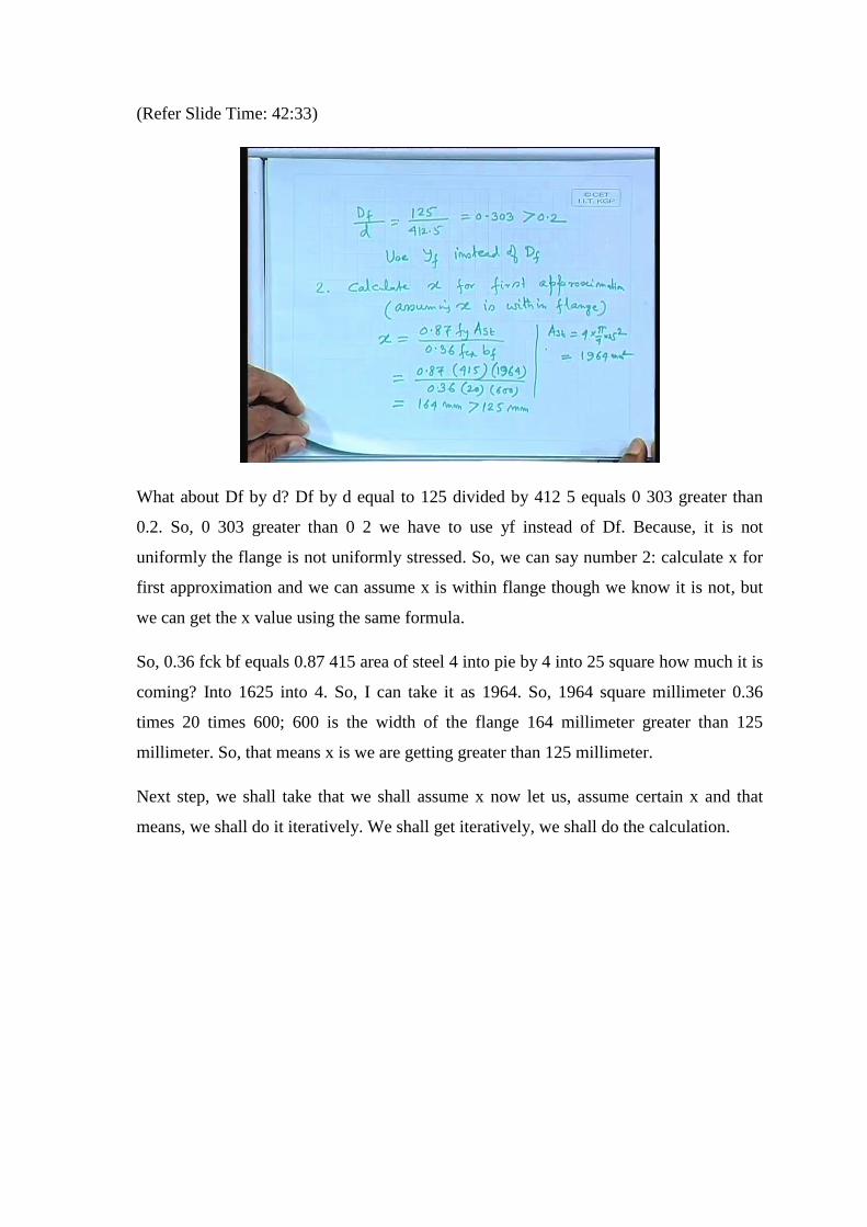
What about Df by d? Df by d equal to 125 divided by 412 5 equals 0 303 greater than
0.2. So, 0 303 greater than 0 2 we have to use yf instead of Df. Because, it is not
uniformly the flange is not uniformly stressed. So, we can say number 2: calculate x for
first approximation and we can assume x is within flange though we know it is not, but
we can get the x value using the same formula.
So, 0.36 fck bf equals 0.87 415 area of steel 4 into pie by 4 into 25 square how much it is
coming? Into 1625 into 4. So, I can take it as 1964. So, 1964 square millimeter 0.36
times 20 times 600; 600 is the width of the flange 164 millimeter greater than 125
millimeter. So, that means x is we are getting greater than 125 millimeter.
Next step, we shall take that we shall assume x now let us, assume certain x and that
means, we shall do it iteratively. We shall get iteratively, we shall do the calculation.

(Refer Slide Time: 45:43)
Assume x equal to 180 millimeter because, it is coming 164 and we have why we are
doing I have assumed the x is within the flange neutral axis is within the flange. On the
basis of that, I have got some x now since, I know 164 so, I am assuming that it may be
180 millimeter. So, assume x equal to 180 millimeter yf equal to 0.15 x plus point 0 65
Df that equivalent depth equal to 108.3 millimeter.
Recalculate, depth of neutral axis width yf. So, we can write down x time 0.36 fck bw
the wave portion plus 0.45 fck times bf minus bw the flange portion times this equivalent
depth should be equal to the tensile force developed in steel. We can write down x 0.36
times 20 times 250 plus 0.45 times 20 that M 20 grade 600 minus 240 times 108 3 equals
0.87 times 415 times 1964 area of steel which comes as 709100 minus 341100 that if you
just rearrange it divided by 1800 equals to 204 millimeter.
So, we have assumed x equal to 180 millimeter and we are getting the x 204 millimeter.
So, let us assume x equal to 200 millimeter we have to do it once more so, let us assume
x equal to 200 millimeter.

(Refer Slide Time: 48:39)
So, let us assume x equal to 200 millimeter. yf equal to 0 15x plus 0 65 Df equals 0 15
times 200 plus 0 65 times 125 equals 111 3 millimeter X times 0.36 times 20 the same
equation we are using plus 0.45 times 20 than 600 minus 250 times 111 3 equals 0.87
times 415 times 1964 or 800x plus 3150 yf equal to 709100 therefore, x equal to 199 2
millimeter that means if we take x equal to 20 millimeter. So, we are getting x equal to
199 2 millimeter. So, in this case we can take x equal to 200 millimeter.
(Refer Slide Time: 50:14)
So, 5: moment capacity by taking moments about steel Mc 1 equal to 0.36 fck bw x d
minus 0 42x equal to 0.36 times 20 times 250 times 200 412.5 minus 0.42 times 200

equal to 1.183 into 10 to the power of 8 newton millimeter equal to 118.3 kilo newton
meter. Mc 2 equal to this is due to balance of the slab remaining part of the slab equals
0.45 fck times bf minus bw times yf not Df yf.
Because, it is not uniformly stress. So, d minus yf by 2 which comes as 0.45 times 20
times 600 minus 250 times 111 times 412.5 minus 111 by 2 equals 1 248 into 10 to the
power of 8 newton millimeter equals 124 8 kilo newton meter. So, we can get that Mcu
equal to Mc 1 plus Mc 2. we shall get Mc 1 plus Mc 2 that, you check Mc 1 plus Mc 2.
(Refer Slide Time: 52:53)
And we can get also, that approximate formula for steel Mu equal to 0.87 fy Ast d minus
Df by 2 from here we shall get it, but here I have written Df approximate I am telling
approximate formula. And if we put all the values, you will get something 2 482 into 10
to the power of 8 newton millimeter equal to 248.2 kilo newton meter, but here we are
giving Dy.
Because, I am not calculating anything on the basis of that steel will yield, on the basis of
that I can get the approximate 248.2 and which is coming. If we are it is good design, we
can come closer to the value because, after all we shall get the balanced section. So, we
shall finish this design of flanged beam here.
Thank you