design of reinforced concrete structures (part ii) …
TRANSCRIPT

1
DESIGN OF REINFORCED CONCRETE
STRUCTURES
(PART II)
Fourth Year
Dr. Nisreen
2020-2021

2

3
TEXT BOOK AND REFERENCES
- Design of Concrete Structures; Arthur H. Nilson, David Darwin, and Charles W. Dolan
- Reinforced Concrete Mechanics and Design; James K. Wight and James G. Macgregor
- Building Design and Construction Handbook; Frederick S. Merritt and Jonathan T. Ricketts - Structural details in Concrete; M. Y. H. Bangash - Manual for the Design of Reinforced Concrete Building Structures; the Institute of
Structural Engineers
- Reinforced Concrete Analysis and Design; S. S. Ray
- Building Code Requirements for Structural Concrete (ACI 318-14) and Commentary on
Building Code Requirements for Structural Concrete (ACI 318R-14) an ACI Standard and
Report; Reported by ACI Committee 318
- Shear Reinforcement for Slabs; Reported by ACI-ASCE Committee 421

4
Notation )الرموز (: a = depth of the effective compression block in a concrete beam A = name for area Ag = gross area, equal to the total area ignoring any reinforcement As = area of steel reinforcement in concrete beam design A's= area of steel compression reinforcement in concrete beam design Ast = area of steel reinforcement in concrete column design Av = area of concrete shear stirrup reinforcement ACI = American Concrete Institute b = width, often cross-sectional bE = effective width of the flange of a concrete T beam cross section bf = width of the flange bw = width of the stem (web) of a concrete T beam cross section c = distance from the top to the neutral axis of a concrete beam (see x)
cc = shorthand for clear cover C = name for centroid, = name for a compression force Cc = compressive force in the compression steel in a doubly reinforced concrete beam Cs = compressive force in the concrete of a doubly reinforced concrete beam d = effective depth from the top of a reinforced concrete beam to the centroid of the tensile steel d´ = effective depth from the top of a reinforced concrete beam to the centroid of the compression steel db = bar diameter of a reinforcing bar D = shorthand for dead load DL = shorthand for dead load E = modulus of elasticity or Young’s modulus, = shorthand for earthquake load Ec = modulus of elasticity of concrete Es = modulus of elasticity of steel f = symbol for stress fc = compressive stress, f
' c = concrete design compressive stress
f pu = tensile strength of the pre-stressing reinforcement f s = stress in the steel reinforcement for concrete design f ' s = compressive stress in the compression reinforcement for concrete beam design f y = yield stress or strength f yt = yield stress or strength of transverse reinforcement F = shorthand for fluid load Fy = yield strength G = relative stiffness of columns to beams in a rigid connection, as is 𝛹 h = cross-section depth H = shorthand for lateral pressure load hf = depth of a flange in a T section Itransformed = moment of inertia of a multi material section transformed to one material k = effective length factor for columns lb = length of beam in rigid joint lc = length of column in rigid joint ld = development length for reinforcing steel ldh = development length for hooks ln = clear span from face of support to face of support in concrete design L = name for length or span length, as is l = shorthand for live load Lr = shorthand for live roof load

5
LL = shorthand for live load Mn = nominal flexure strength with the steel reinforcement at the yield stress and concrete at the concrete design strength for reinforced concrete beam design Mu = maximum moment from factored loads for LRFD beam design n = modulus of elasticity transformation coefficient for steel to concrete n.a. = shorthand for neutral axis (N.A.) pH = chemical alkalinity P = name for load or axial force vector Po = maximum axial force with no concurrent bending ( الانحناء المتزامن) moment in a reinforced concrete column Pn = nominal column load capacity in concrete design Pu = factored column load calculated from load factors in concrete design R = shorthand for rain or ice load = radius of curvature in beam deflection relationships (see r ) Rn = concrete beam design ratio = Mu/bd2 s = spacing of stirrups in reinforced concrete beams S = shorthand for snow load t = name for thickness T = name for a tension force = shorthand for thermal load U = factored design value Vc = shear force capacity in concrete Vs = shear force capacity in steel shear stirrups Vu = shear at a distance of d away from the face of support for reinforced concrete beam design wc = unit weight of concrete wDL = load per unit length on a beam from dead load wLL = load per unit length on a beam from live load wself wt = name for distributed load from self-weight of member wu = load per unit length on a beam from load factors W = shorthand for wind load x = horizontal distance = distance from the top to the neutral axis of a concrete beam (see c)
y = vertical distance β1 = coefficient for determining stress block height, a, based on concrete strength, f ' c Δ = elastic beam deflection ε = strain εt = strain in the steel εy = strain at the yield stress λ = modification factor for light weight concrete Ø = resistance factor Ø c = resistance factor for compression Ɣ= density or unit weight ρ = radius of curvature in beam deflection relationships (see R) = reinforcement ratio in concrete beam design = As/bd ρ balanced = balanced reinforcement ratio in concrete beam design vc = shear strength in concrete design

6
STRUCTURAL SYSTEM AND LOAD PATHS
The structural system shall include (a) through (g), as applicable:
(a) Floor construction and roof construction, including one-way and two-way slabs
(b) Beams and joists
(c) Columns
(d) Walls
(e) Diaphragms
(f) Foundations
(g) Joints, connections, and anchors as required to transmit forces from one component to
another.
Load factors and combinations:
Required strength (U) shall be at least equal to the effects of factored loads in Table 5.3.1,
with exceptions and additions in 5.3.3 through 5.3.12.
All members and structural systems shall be analyzed for the maximum effects of loads
including the arrangements of live load in accordance with 6.4.
Strength:
Design strength of a member and its joints and connections, in terms of moment, axial force,
shear, torsion, and bearing, shall be taken as the nominal strength (Sn) multiplied by the
applicable strength reduction factor (ø).
Structures and structural members shall have design strength at all sections (ø Sn)
greater than or equal to the required strength (U) calculated for the factored loads and forces
in such combinations as required by ACI-Code.
Design strength ≥ required strength ∴ ø Sn ≥ U

7
TYPES OF SLABS
1. One-way slab: Slabs may be supported on two opposite sides only, in such case, the
structural action of the slab is essentially "one-way", and the loads are carried by the slab
in the direction perpendicular to the supporting beams, Figure (1-a).
الهيكلي العمل ، الحالة هذه مثل في ، فقط متقابلين جانبين على هذا النوع من السقف دعم يمكن: الاتجاه ديأحا السقف جسورال على العمودي الاتجاه في سقفال بواسطة الأحمال حمل ويتم ،" واحد اتجاه" الأساس في هو للبلاطة (. أ -1) الشكل ، الداعمة
2. Two-way slab: Slabs have beam or support on all four sides. The loads are carried by the
slab in two perpendicular directions to the supporting beams; Figure (1-b).
نقل يتم. الأربعة الجوانب على أو جسر دعامة أو عارضة على الألواح السقوف أو تحتوي: الاتجاه ثنائية لاطةالسقف او الب(. ب -1) الشكل ؛ الداعمة جسورال مع متعامدين اتجاهين في البلاطة بواسطة الأحمال
3. If the ratio of length to width of one slab panel is larger than 2, most of the load is carried
by the short direction to the supporting beams, and one-way action is obtained in effect,
even though supports are provided on all sides, Figure (1-c).
إلى القصير الاتجاه طريق عن الحمل معظم نقل يتم ، ( 2) من أكبر واحد لوح للوح العرض إلى الطول نسبة كانت إذا جميع من الدعامات توفير من الرغم على ، المفعول ساري الاتجاه أحادي إجراء على الحصول ويتم ، الداعمة الحزم
(.ج -1) شكل ، الجوانب
4. Concrete slab carried directly by columns, without the use of beams or girders, such slab
is described by flat plates, and are commonly used where spans are not large and loads
are not heavy, Figure (1-d).
هذه وصف يتم ، العوارض أو جسورال استخدام بدون ، أعمدة بواسطة مباشرة محمولة خرسانيةال بلاطةالسقف أو ال الأحمال تكون ولا كبيرة الامتدادات فيها تكون لا التي الأماكن في شائع بشكل وتستخدم ، مسطحة بألواح السقوف
(. د -1) الشكل ، ثقيلة
5. Flat slabs are also beamless slab with column capitals, drop panels, or both, Figure (1-e).
، كليهما أو منسدلة ألواح أو أعمدة تيجان ذات ملحومة غير بلاطات أيضًا هي المسطحة الألواحالسقوف أو
(. هـ-1) الشكل
6. Two–way joist systems (grid slab), to reduce the dead load of solid-slab, voids are
formed in a rectilinear pattern through use of metal or fiberglass form inserts. A two–way ribbed construction results (waffle slab). Usually inserts are omitted near the
columns, Figure (1-f).
من مستقيم نمط في الفراغات تتشكل ، الصلبة للبلاطة الميت الحمل لتقليل ،(شبكي لوح) الاتجاه ثنائية رافدة أنظمة السقف نوع) الاتجاه ثنائية مضلعة بناء نتائج. الزجاجية الألياف من مصنوعة أو معدنية حشوات استخدام خلال (.و -1) الشكل ، الأعمدة من بالقرب الإدخالات حذف يتم ما عادة (.الوافل

8
One-way slabs: slabs reinforced to resist flexural stresses in only one direction.
Two-way slabs: reinforced for flexure in two directions.
Column capital: enlargement of the top of a concrete column located directly below the slab
or drop panel that is cast monolithically with the column.
.العمود مع موحد بشكل المصبوب المسقط اللوح أو البلاطة أسفل مباشرة يقع خرساني عمود من العلوي الجزء توسيع
Drop panel: projection below the slab used to reduce the amount of negative reinforcement
over a column or the minimum required slab thickness, and to increase the slab shear
strength.
ولزيادة ، البلاطة سماكة من المطلوب الأدنى الحد أو عمود فوق السلبي التعزيز كمية لتقليل اللوح أسفل الإسقاط يستخدمأو السقف. اللوح قص مقاومة .
Panel: slab portion bounded by column, beam, or wall centerlines on all sides.
الجوانب جميع من الحائط على مركزية خطوط أو جسر أو عمود يحده بلاطةالسقف أو ال جزء
Column strip: a design strip with a width on each side of a column centerline equal to the
lesser of 0.25 ℓ2 and 0.25 ℓ1. A column strip shall include beams within the strip, if present.
من أقل يساوي للعمود الوسط خط من جانب كل على بعرضالشريحة تصميم شريط
.0.25 ℓ2 and 0.25 ℓ1 وجد إن ، الشريط داخل عوارض على العمود شريط يشتمل أن يجب
Middle strip: a design strip bounded by two column strips.
.العمود من حتينشري يحده ممتص حةشري .
(a)
(b)
(d)
(c)

9
Size and projection of drop panel
In computing required slab reinforcement, the thickness of drop panel below the slab shall
not be assumed greater than one – quarter the distance from edge of drop panel to edge of
column or column capital.
(e)
(f)
Types of slabs
(a) one-way slab, (b) two-way slab, (c) one-way slab, (d) flat plate, (e) flat slab,
(f) two–way joist

10
The column capital is normally 20 to 25% of the average span length.
Design of one–way slab systems:
At point of intersection (P) the deflection must be the same
∆ = 5 w L4384E I ⇒ 5 wa La4384 E I = 5 wb Lb4384 E I ∴ wawb = Lb4La4 if LbLa = 2 ∴ wawb = 16 ⇒ wa = 16 wb
For purposes of analysis and design a unit strip of such a slab cut out at right angles to
the supporting beam may be considered as a rectangular beam of unit width (1.0 m) with a
depth (h) equal to the thickness of the slab and a span (La) equal to the distance between
supported edges.
La
Lb
P
11
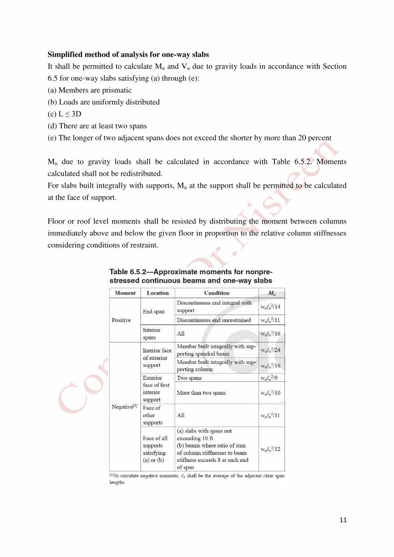
Simplified method of analysis for one-way slabs
It shall be permitted to calculate Mu and Vu due to gravity loads in accordance with Section
6.5 for one-way slabs satisfying (a) through (e):
(a) Members are prismatic
(b) Loads are uniformly distributed
(c) L ≤ 3D
(d) There are at least two spans
(e) The longer of two adjacent spans does not exceed the shorter by more than 20 percent
Mu due to gravity loads shall be calculated in accordance with Table 6.5.2. Moments
calculated shall not be redistributed.
For slabs built integrally with supports, Mu at the support shall be permitted to be calculated
at the face of support.
Floor or roof level moments shall be resisted by distributing the moment between columns
immediately above and below the given floor in proportion to the relative column stiffnesses
considering conditions of restraint.

12
A minimum area of flexural reinforcement (As,min) shall be provided in accordance with
Table 7.6.1.1.
Table 7.6.1.1—As,min for nonprestressed one-way slabs
Reinforcement type fy
(MPa)
As,min
(mm)
Deformed bars < 420 0.0020 Ag
Deformed bars or welded wire reinforcement 420 Greater of:
0.0018 × 420fy Ag
0.0014 Ag
Reinforcement for shrinkage and temperature stresses normal to the principal reinforcement
should be provided in a structural slab. ACI Code specifies the minimum ratios of
reinforcement area to gross concrete area, as shown in Table 24.4.3.2.
Table 24.4.3.2—Minimum ratios of deformed shrinkage and temperature
reinforcement area to gross concrete area
Reinforcement type fy
(MPa) Minimum reinforcement ratio
Deformed bars < 420 0.0020
Deformed bars or welded wire reinforcement 420 Greater of:
0.0018 × 420fy
0.0014
The spacing of deformed shrinkage and temperature reinforcement shall not exceed the lesser
of 5h and 450 mm.
Vu due to gravity loads shall be calculated in accordance with Table 6.5.4.
For slabs built integrally with supports, Vu at the support shall be permitted to be calculated
at the face of support.

13
TWO WAY SLAB
Moment and moment variations in a uniformly loaded slab with simple supports on four sides.
Distribution of total static moment to critical sections for positive and negative bending.

14
Column supported two way slabs: (a) two way slabs with beam, (b) two way slab without beam.
15
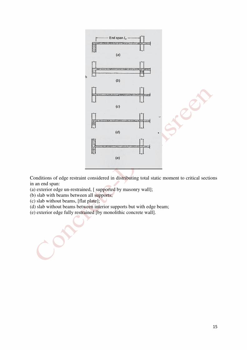
Conditions of edge restraint considered in distributing total static moment to critical sections in an end span: (a) exterior edge un-restrained, [ supported by masonry wall]; (b) slab with beams between all supports; (c) slab without beams, [flat plate]; (d) slab without beams between interior supports but with edge beam; (e) exterior edge fully restrained [by monolithic concrete wall].

16
DESIGN OF TWO-WAY SLAB SYSTEMS
Reinforced concrete slabs (R. C. Slabs) are usually designed for loads assumed to be uniformly distributed over on entire slab panel, bounded by supporting beam or column center-lines.
، كاملة بلاطة لوحة على موحد بشكل توزيعها يتم أن يفُترض التي للأحمال المسلحة الخرسانية الألواح تصميم يتم ما عادةً العمود مركز خطوط أو الدعم جسر ويحدها
. General design concept of ACI Code
1- Imagining vertical cuts are made through the entire building along lines midway between columns.
تخيل القطع العمودية تتم من خلال المبنى بأكمله على طول خطوط بين الأعمدة
2- The cutting creates a series of frames whose width center lines lie along the column lines.
ان القطع يخلق سلسلة من الإجزاء التي خطوط السنتر للعرض تمتد على طول خطوط العمود
3- The resulting series of rigid frames, taken separately in the longitudinal and transverse directions of the building.
النتيجة هي سلسلة من الأطر الصلبة، التي تؤخذ بشكل منفصل في الاتجاهات الطولية والمستعرضة للمبنى 4- A typical rigid frame would consist of:
a- The columns above and below the floor. b- The floor system, with or without beams, bounded laterally between the center
lines of the two panels. يتألف الإطار الصلب النموذجي من -
الأعمدة فوق وتحت الأرضية )الطابق( -أ . نظام الأرضية )الطابق(, مع أو بدون عوارض )جسور(، محصورة أفقيا بين خطوط لوحين -ب
5- Two methods of design are presented by the ACI Code:
a- Direct Design Method (DDM): An approximants method using moment and shear coefficients, Section 8.10 in ACI Code.
b- Equivalent Frame Method (EFM): More accurate using structural analysis after assuming the relative stiffness of the members, Section 8.11 in ACI Code.
:طريقتين للتصميم يتم عرضها من خلال الكود الأمريكي -في الكود الأمريكي 8.10طريقة التصميم المباشر :وهي طريقة تقريبية باستخدام معاملات العزم والقص، الجزء -أ
8.11للأجزاء، الجزء طريقة الإطار المكافئ :وهي أكثر دقة باستخدام التحليل الهيكلي بعد افتراض الصلابة النسبية -ب .في الكود الأمريكي.

17
Floor plan
.
18
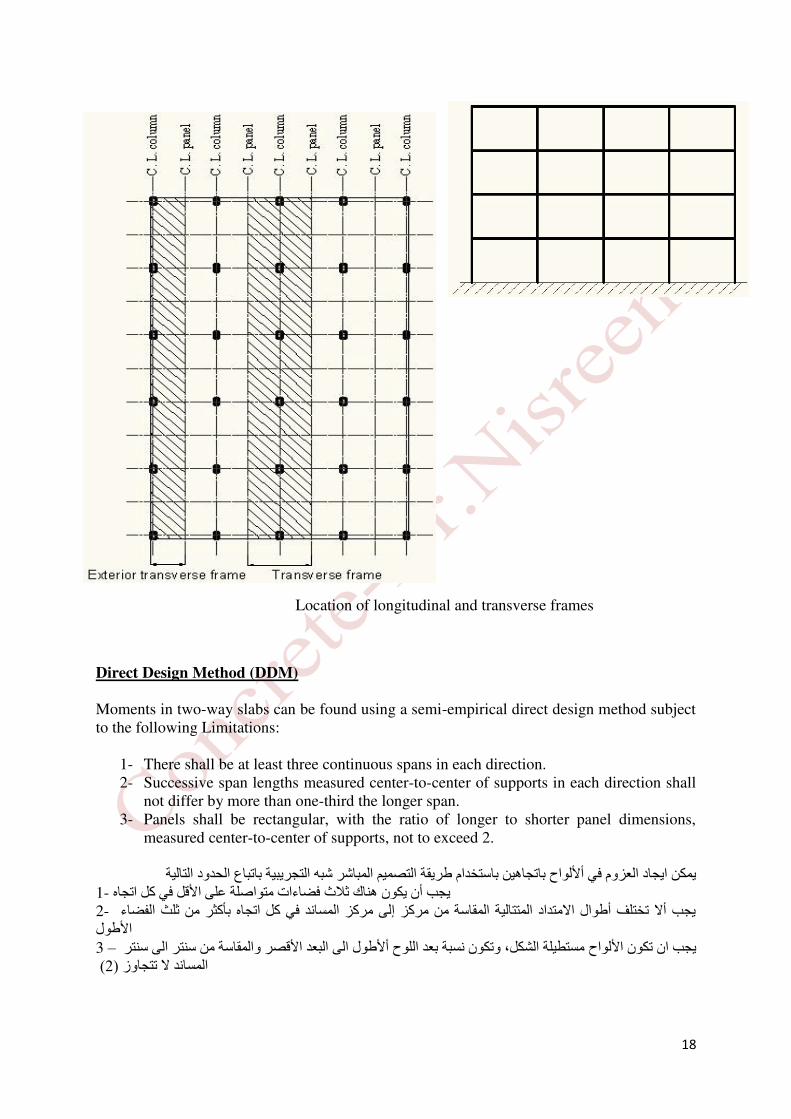
Direct Design Method (DDM)
Moments in two-way slabs can be found using a semi-empirical direct design method subject to the following Limitations:
1- There shall be at least three continuous spans in each direction. 2- Successive span lengths measured center-to-center of supports in each direction shall
not differ by more than one-third the longer span. 3- Panels shall be rectangular, with the ratio of longer to shorter panel dimensions,
measured center-to-center of supports, not to exceed 2.
ريقة التصميم المباشر شبه التجريبية باتباع الحدود التاليةيمكن ايجاد العزوم في ألألواح باتجاهين باستخدام ط يجب أن يكون هناك ثلاث فضاءات متواصلة على الأقل في كل اتجاه -1يجب ألا تختلف أطوال الامتداد المتتالية المقاسة من مركز إلى مركز المساند في كل اتجاه بأكثر من ثلث الفضاء -2 الأطولمستطيلة الشكل، وتكون نسبة بعد اللوح ألأطول الى البعد الأقصر والمقاسة من سنتر الى سنتر يجب ان تكون الألواح – 3
( 2المساند لا تتجاوز )
Location of longitudinal and transverse frames .

19
4- Column offset shall not exceed 10 percent of the span in direction of offset from either axis between centerlines of successive columns.
5- All loads shall be due to gravity only and uniformly distributed over an entire panel. 6- Un-factored live load shall not exceed two times the un-factored dead load. 7- For a panel with beams between supports on all sides, Eq. (8.10.2.7a) shall be
satisfied for beams in the two perpendicular directions. % من الفضاء في اتجاه التخالف من أي من المحاور بين الخطوط المركزية 10يجب ألا يتجاوز تخالف العمود - 4 للأعمدة المتعاقبة أو المتخالفة .يجب أن تكون جميع الأحمال بسبب الجاذبية فقط وتوزيعها بشكل منتظم على لوحة كاملة -5 .يجب أن لا يتجاوز الحمل الحي غير مضروب بالمعامل مرتين من الحمل الميت أيضا غيرمضروب بمعامل -6للالواح مرتبطة مع جسور بين المساند و بكل الأتجاهات يجب ان تكون مكافئة للجسور في الأتجاهين المتعامدين -7 وحسب المعادلة: 0.2 ≤ αf1ℓ22αf2ℓ12 ≤ 5.0 (8.10.2.7a) ℓ1: is defined as the span in the direction of the moment analysis, and ℓ2: as the span in lateral direction. Spans ℓ1& ℓ2 are measured to column centerlines. αf1 and αf2 are calculated by: αf = EcbIbEcsIs
EcbIb: The elasticity and moment of inertia of beam. EcsIs: The elasticity and moment of inertia of beam.
∝𝑓 : Ratio of flexural stiffness of beam section to flexural stiffness of a width of slab bounded
laterally by centerlines of adjacent panels, if any, in each side of the beam. نسبة صلابة الانحناء للجسر)العتبة( إلى صلابة الانحناء من عرض بلاطة )سقف( محصورة أفقيا بواسطة خطوط مركزية لللوحات المجاورة، إن وجدت، في كل جانب من الجسر )العتبة(. ∝𝑓1: ∝𝑓 in direction of 𝑙1 ∝𝑓2: ∝𝑓 in direction of 𝑙2
The direct design method consists of a set of rules for distributing moments to slab and beam sections to satisfy safety requirements and most serviceability requirements simultaneously.
أقسام السقف والجسر )العتبة( لتلبية متطلبات على زوموتتكون طريقة التصميم المباشر من مجموعة من القواعد لتوزيع الع .السلامة ومعظم متطلبات الخدمة في وقت واحد. Three fundamental steps are involved as follows: (1) Determination of the total factored static moment (Section 8.10.3). (2) Distribution of the total factored static moment to negative and positive sections (Section 8.10.4). (3) Distribution of the negative and positive factored moments to the column and middle strips and to the beams, if any (Sections 8.10.5 and 8.10.6).
20
The distribution of moments to column and middle strips is also used in the equivalent
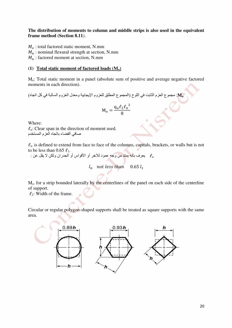
frame method (Section 8.11). 𝑀𝑜 : total factored static moment, N.mm 𝑀𝑛 : nominal flexural strength at section, N.mm 𝑀𝑢 : factored moment at section, N.mm (1) Total static moment of factored loads (Mo)
Mo: Total static moment in a panel (absolute sum of positive and average negative factored moments in each direction). Mo: مجموع العزم الثابت في اللوح )المجموع المطلق للعزوم الإيجابية ومعدل العزوم السالبة في كل اتجاه( Mo = quℓ2ℓn28
Where: ℓn: Clear span in the direction of moment used. صافي الفضاء باتجاه العزم المستخدم ℓn: is defined to extend from face to face of the columns, capitals, brackets, or walls but is not to be less than 0.65 ℓ1. يقل عن : يعرف بأنه يمتد من وجه عمود للاخر أو الأقواس أو الجدران ولكن لا ℓn 𝑙𝑛 𝑛𝑜𝑡 𝑙𝑒𝑠𝑠 𝑡ℎ𝑎𝑛 0.65 𝑙1 Mo: for a strip bounded laterally by the centerlines of the panel on each side of the centerline of support. ℓ2: Width of the frame. Circular or regular polygon-shaped supports shall be treated as square supports with the same area.

21
(2) Longitudinal distribution of Mo
(a) Interior spans:
Mo : is apportioned between the critical positive and negative bending sections according to the following ratios:-
العزم الثابت يكون موزع بين أقسام الانحناء الإيجابية والسلبية الحرجة وفقا للنسب التالية: Neg. Mu = 0.65 Mo Pos. Mu = 0.35 Mo The critical section for a negative bending is taken at the face of rectangular supports, or at the face of an equivalent square support having the same sectional area. القسم الحرج للإنحناء)العزم( السالب يؤخذ في وجه المساند المستطيلة، أو في وجه المسند المربع المكافئ له نفس مساحة المقطع.
(b) End span: In end spans, the apportionment of the total static moment (Mo) among the three critical moment sections (interior negative, positive, and exterior negative) depends upon the flexural restraint provided for the slab by the exterior column or the exterior wall and upon the presence or absence of beams on the column lines. End span, Mo shall be distributed in accordance with Table 8.10.4.2.
ب( الفضاء النهائي: في نهاية الفضاءات، يعتمد توزيع مجموع العزم الثابت بين الأجزاء الحرجة الثلاثة )العزم الداخلي الانثناء مجهزة للوح من العمود الخارجي أو السالب، العزم الموجب، والعزم السالب الخارجي( ويعتمد على حدود
والجدار الخارجي وفي وجود أو عدم وجود الجسر )العتبة( على خطوط العمود. العزم الثابت للفضاء النهائي او الأخير 8.10.4.2يوزع حسب الجدول .
Note: At interior supports, negative moment may differ for spans framing into the common support. In such a case the slab should be designed to resist the larger of the two moments.

22
(3) Lateral distribution of moments
After the moment Mo distributed on long direction to the positive and negative moments, then these moments must distribute in lateral direction across the width, which consider the moments constant within the bounds of a middle strip or column strip. The distribution of moments between middle strips and column strip and beams depends upon:
1. The ratio ℓ2/ ℓ1. 2. The relative stiffness of the beam and the slab. 3. The degree of torsional restraint provided by the edge beam.
التوزيع الجانبي للعزوم:
الطولي إلى العوزم الموجبة والسالبة، ثم يجب توزيع هذه العزوم في الاتجاه الجانبي بعد توزيع العزم الثابت على الأتجاه
وخلال العرض، والتي تعتبر أن العزوم ثابتة داخل حدود الشريط الوسطي أو شريط العمود. يعتمد توزيع العزوم بين الشرائط الوسطى وشريط العمود والجسور)العتبات( على:
.ℓ2/ ℓ1 نسبة .1النسبية للجسر)العتبة( والبلاطة )السقف(الصلابة .2 . .درجة ضبط الالتواء التي تحدث بواسطة الجسر في الحافة .3
The column strip shall resist the portion of interior negative Mu in accordance with Table 8.10.5.1.
8.10.5.1للجدول يجب أن يقاوم شريط العمود جزء من العزم الداخلي السالب وفقا .
Figure (4) longitudinal distribution of Mo
.
end span interior span interior span end span
.
ℓn
.

23
The column strip shall resist the portion of exterior negative Mu in accordance with Table 8.10.5.2.
. 8.10.5.2يجب أن يقاوم جزء من العزم الخارجي السالب وفقا للجدول شريط العمود
𝛽𝑡 : ratio of torsional stiffness of edge beam section to flexural stiffness of a width of slab equal to span length of beam, center to center of supports.
عرض السقف من الانحناء)الأنثناء( صلابة لمقطع الجسر )العتبة( في حافة السقف إلى الالتواء صلابة هي نسبة
المساند. مركز إلى مركز الجسر،من مساوي لطول )البلاطة( 𝐶: cross sectional constant to define torsional properties of slab and beam.
x: shorter overall dimension of rectangular part of cross section, mm y: longer overall dimension of rectangular part of cross section, mm The column strip shall resist the portion of positive Mu in accordance with Table 8.10.5.5.

24
A convenient parameter defining the relative stiffness of the beam and slab spanning in either direction is:
هي: الاتجاهين من أي في تمتد التي والبلاطة للجسر النسبية الصلابة تحدد المعامل المناسب والتي
αf = EcbIbEcsIs = IbIs
Where: Ecb and Ecs are the moduli of elasticity of beam and slab concrete (usually the same), respectively. Ib and Is are the moment of inertia of the effective beam and slab, respectively. The flexural stiffness of the beam and slab are based on the gross concrete section. Variation due to column capitals and drop panels are neglected (in applying DDM).
لأنواع الترابط بين العمود والسقف التباين إهمال الخرسانة. يتم مقطع على والبلاطة تعتمد للجسر الأنثناء صلابة ويستند

25
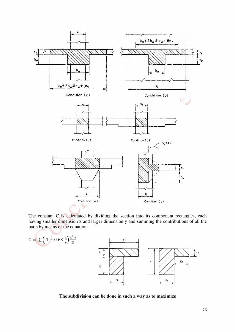
For monolithic or fully composite construction supporting two-way slabs, a beam includes that portion of slab, on each side of the beam extending a distance equal to the projection of the beam above or below the slab, whichever is greater, but not greater than four times the slab thickness.
من الجزء ذلك على الجسور تشتمل اتجاهين والتي ذات يدعم سقوف الذي بالكامل المركب المتجانس أو بالبناء يتعلق وفيما
أكبر وليس أكبر، أيهما البلاطة، أسفل أو لمسقط الجسرأعلى مساوية مسافة تمتد التي الجسر من جانب كل على السقف،السقف )اليلاطة(. سمك مرات أربع من
The Moment of Inertia of Flanged Section
Ib = k bwh312
k ≈ 1.0 + 0.2 (bEbw) for 2 < bEbw < 4 & 0.2 < hfh < 0.5
The relative restraint provided by the torsional resistance of the effective transverse edge beam is reflected by the parameter 𝛽𝑡, defined by:
بالمعامل: الفعال ينعكس المستعرض للجسرالذي بالحافة الالتوائية المقاومة توفره الذي النسبي التقيد βt = EcbC2 EcsIs = C2 Is
C: The torsional rigidity of the effective transverse beam, which is defined as the largest of the following three items:- a- A portion of the slab having a width equal to that of the column, bracket, or capital in the
direction in which moment are taken, c1 (case of no actual beam).
b- The portion of the slab specified in (a) plus that part of any transverse beam above and below the slab.
c- The transverse beam defined as before (in calculating αf).
26
The constant C is calculated by dividing the section into its component rectangles, each having smaller dimension x and larger dimension y and summing the contributions of all the parts by means of the equation: C = ∑ ( 1 − 0.63 xy) x3 y3
The subdivision can be done in such a way as to maximize
27
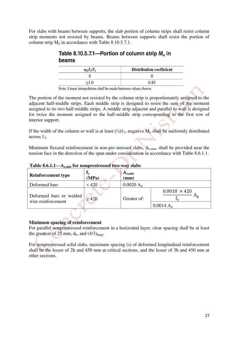
For slabs with beams between supports, the slab portion of column strips shall resist column strip moments not resisted by beams. Beams between supports shall resist the portion of column strip Mu in accordance with Table 8.10.5.7.1. The portion of the moment not resisted by the column strip is proportionately assigned to the adjacent half-middle strips. Each middle strip is designed to resist the sum of the moment assigned to its two half-middle strips. A middle strip adjacent and parallel to wall is designed for twice the moment assigned to the half-middle strip corresponding to the first row of interior support. If the width of the column or wall is at least (¾)ℓ2, negative Mu shall be uniformly distributed across ℓ2. Minimum flexural reinforcement in non-pre-stressed slabs, As,min, shall be provided near the tension face in the direction of the span under consideration in accordance with Table 8.6.1.1.
Table 8.6.1.1—As,min for nonprestressed two-way slabs
Reinforcement type fy
(MPa)
As,min
(mm)
Deformed bars < 420 0.0020 Ag
Deformed bars or welded wire reinforcement
420 Greater of:
0.0018 × 420fy Ag
0.0014 Ag
Minimum spacing of reinforcement For parallel nonprestressed reinforcement in a horizontal layer, clear spacing shall be at least the greatest of 25 mm, db, and (4/3)dagg. For nonprestressed solid slabs, maximum spacing (s) of deformed longitudinal reinforcement shall be the lesser of 2h and 450 mm at critical sections, and the lesser of 3h and 450 mm at other sections.

28
Example 1:
For the the longitudinal interior frame (Frame A) of the falt plate floor shown in Figure,by using the Direct Design Method, find:
a. Longitudinal distribution of the total static moment at factored loads. b. Lateral distribution of the moment at exterior support.
Slab thickness = 200 mm, d = 165 mm qu = 15.0 kN/m2 All edge beams = 250×500 mm All columns = 500×500 mm fc
' = 25 MPa, fy = 400 MPa Solution a.) for Frame A ℓ1 = 5000 mm ℓ2 = 6400 mm ℓn = ℓ1 –500 = 5000 – 500 = 4500 mm Mo = quℓ2ℓn28 Mo = 15×6.4×(4.5)28
= 243 kN.m Longitudinal distribution of total static moment at factored loads Interior span: Neg. Mu = 0.65 Mo Pos. Mu = 0.35 Mo End span:

29
b.)
Negative moment at exterior support Total moment = 72.9 kN.m αf = 0 for edge beam choose the section of edge beam
3
yx
y
x63.01C
3
3
500250
500
25063.01
3
300200
300
20063.01C
33
1
4
1 mm.6672247854166C
3
300250
300
25063.01
3
550200
550
20063.01C
33
2
4
2 mm.6671872854166C
4mm.6672247854166C
Is = 112 × ℓ2 × 𝑡3 = 112 × 6400 × (200)3 = 4266666666.667 mm4
scs
cbt
IE2
CE
; cscb EE
0.5 Mo
121.5 kN.m
0.3 Mo
72. 9 kN.m 0.7 Mo
170.1
0.35 Mo
85.05 kN.m
0.65 Mo
157.95 kN.m
0.65 Mo
157.95 kN.m
Longitudinal distribution of total static moment at factored loads

30
263.0.66742666666662
.6672247854166
I2
C
st
ℓ2ℓ1 = 6.45.0 = 1.28
ℓ2 ℓ1⁄ 1.0 1.28 2.0
0.0t 100 100 100
263.0t 97.37
5.2t 75 75 75
Negative moment at column strip = 72.9×0.9737 = 70.983 kN.m Negative moment at middle strip = 72.9-70.983 = 1.917 kN.m Example 2:
For the the longitudinal interior frame of the falt plate floor shown in Figure, by using the Direct Design Method, find:
a. Longitudinal distribution of total static moment at factored loads. b. Lateral distribution of moment at exterior panel.
Slab thickness = 180 mm, d = 150 mm qu = 14.0 kN/m2 All edge beams = 250×500 mm All columns = 400×400 mm fc
' = 24 MPa, fy = 400 MPa Solution a.)
for Frame A ℓ1 = 5000 mm ℓ2 = 6500 mm ℓn = ℓ1 –400 = 5000 – 400 = 4600 mm Mo = quℓ2ℓn28
Mo = 14×6.5×(4.6)28
= 240.695 kN.m

31
Longitudinal distribution of total static moment at factored loads Interior span: Neg. Mu = 0.65 Mo Pos. Mu = 0.35 Mo End span:
b.)
exterior panel 1- Negative moment at exterior support Total moment = 72.209 kN.m αf = 0 for edge beam choose the section of edge beam
3
yx
y
x63.01C
3
3
500250
500
25063.01
3
320180
320
18063.01C
33
1
41 mm7.2185484566C
0.5 Mo
120.348 kN.m
0.3 Mo
72.209 kN.m 0.7 Mo
168.487
0.35 Mo
84.243 kN.m
0.65 Mo
156.452 kN.m 0.65 Mo
156.452 kN.m
Longitudinal distribution of total static moment at factored loads

32
3
320250
320
25063.01
3
570180
570
18063.01C
33
2
42 mm7.1733984566C
4mm7.2185484566C
Is = 112 × ℓ2 × 𝑡3 = 112 × 6500 × (180)3 = 3159000000 mm4
scs
cbt
IE2
CE
; cscb EE
346.031590000002
7.2185484566
I2
C
s
t
ℓ2ℓ1 = 6.55.0 = 1.3
ℓ2 ℓ1⁄ 1.0 1.3 2.0
0.0t 100 100 100
346.0t
5.2t 75 75 75
Negative moment at column strip = 72.209 × = kN.m Negative moment at middle strip = 72.209 - = kN.m 2- Positive moment Total moment = 120.348 kN.m αf = 0 3- Negative moment at interior support Total moment = 168.487 kN.m αf = 0

33
Example 3:
For the the longitudinal interior frame (Frame A) of the falt plate floor shown in Figure, by using the Direct Design Method, find:
a- Longitudinal distribution of the total static moment at factored loads. b- Lateral distribution of moment at interior panel (column and middle strip moments at
negative and positive moments). Solution a.
m0.4
4.04.4
5.0LL 1n
8
LLwM
2n2u
o
kN.m381
8
0.46.415M
2
o
mm400400columnsAll
m/kN0.15q
mm150d,mm180thicknessSlab2
u
0.52 Mo
71.76
0.26 Mo
35.88 0.7 Mo
96.6
0.35 Mo
48.3
0.65 Mo
89.7 0.65 Mo
89.7
Longitudinal distribution of total static moment at factored loads

34
b.
interior panel
1) Negative moment Total moment = 89.7 kN.m
01
Negative moment at column strip = 89.7×0.75 = 67.275 kN.m Negative moment at midlle strip = 89.7-67.275 = 22.425 kN.m
2) Positive moment Total moment = 48.3 kN.m
01
Negative moment at column strip = 48.3×0.60 = 28.98 kN.m Negative moment at midlle strip = 48.3-28.98 = 19.32 kN.m Home Work 1:
For the the transverse interior frame (Frame C) of the flat plate floor with edge beams shown in Figure, by using the Direct Design Method, find::
1) Longitudinal distribution of total static moment at factored loads. 2) Lateral distribution of moment at interior panel (column and middle strip moments at
negative and positive moments). 3) Lateral distribution of moment at exterior panel (column and middle strip moments at
negative and positive moments).
mm500500columnsAll
mm500250beamsedgeAll
m/kN0.16q
mm150d,mm180thicknessSlab2
u
35
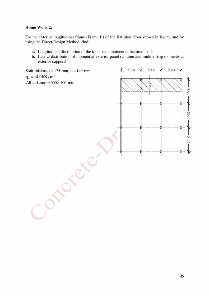
Home Work 2:
For the exterior longitudinal frame (Frame B) of the flat plate floor shown in figure, and by using the Direct Design Method, find::
a. Longitudinal distribution of the total static moment at factored loads. b. Lateral distribution of moment at exterior panel (column and middle strip moments at
exterior support)
mm140d,mm175thicknessSlab 2
u m/kN0.14q
mm400600columnsAll