design of reinforced concrete sections according to … · design of reinforced concrete sections...
TRANSCRIPT
IDEA RS s.r.o. | South Moravian Innovation Centre, U Vodarny 2a, 616 00 BRNO tel.: +420 - 511 205 263, fax: +420 - 541 143 011, www.idea-rs.cz
Design of reinforced concrete sections
according to EN 1992-1-1 and EN 1992-2
Educational text for practical seminar
2D members
Brno, 25. 1. 2011
Design of reinforced concrete sections according to EN 1992-1-1 and EN 1992-2 Brno, 25. 1. 2011
Page 2
Content
1. Types of 2D members ........................................................................................................ 4
1.1. Slab .............................................................................................................................. 4
1.2. Shell as slab – Shell-slab ............................................................................................. 4
1.3. Wall ............................................................................................................................. 4
1.4. Shell as wall – Shell-wall ............................................................................................ 4
1.5. Deep beam ................................................................................................................... 4
2. Input of reinforcement ........................................................................................................ 5
2.1. Input of reinforcement using reinforcement templates ................................................ 5
2.2. Input of general reinforcement .................................................................................... 6
2.3. Type of reinforcement ................................................................................................. 6
3. Internal forces ..................................................................................................................... 7
3.1. Input of internal forces ................................................................................................ 7
3.2. Determining direction of check ................................................................................... 8
3.2.1. Analýza směru posouzení pro mezní stav únosnosti ............................................ 9
3.3. Recalculation of internal forces to directions of check ............................................. 10
3.3.1. Calculation of normal forces at both surfaces of 2D element ............................ 10
3.3.2. Calculation of internal forces at both surfaces ................................................... 12
3.3.3. Calculation of recalculated internal forces at surfaces to the defined check direction ............................................................................................................................ 13
3.3.4. Transformation of recalculated internal forces to the centroid of cross-section 14
3.3.5. Recalculation of shear forces to the defined direction of check......................... 15
3.4. Comparison of internal forces recalculation using various methods ......................... 16
3.4.1. Recalculation of forces acc. to ENV 1992-1-1 .................................................. 16
3.4.2. Comparison of internal forces calculation with programs RFEM and SCIA Engineer ........................................................................................................................... 18
4. Check ................................................................................................................................ 19
4.1. Results of check in defined directions ....................................................................... 19
4.2. Ultimate limit state .................................................................................................... 20
4.2.1. Capacity check ................................................................................................... 20
4.2.2. Response check .................................................................................................. 20
4.2.3. Interaction check ................................................................................................ 20
4.2.4. Capacity check comparison between IDEA Concrete, RFEM and SCIA Engineer ........................................................................................................................... 20
4.3. Serviceability limit state ............................................................................................ 21
4.3.1. Stress limitation .................................................................................................. 21
Design of reinforced concrete sections according to EN 1992-1-1 and EN 1992-2 Brno, 25. 1. 2011
Page 3
4.3.2. Crack width check .............................................................................................. 21
4.4. Detailing provisions ................................................................................................... 21
5. Literature .......................................................................................................................... 23

Design of reinforced concrete sections according to EN 1992-1-1 and EN 1992-2 Brno, 25. 1. 2011
Page 4
1. Types of 2D members
1.1. Slab
According to EN 1992-1-1, art. 5.3.1(4) a slab is a member, for which the minimum panel dimension is not less than 5 times the overall slab thickness. Slab is loaded only by bending moments and shear forces perpendicular to centroidal plane of slab. Detailing provisions check is performed according to EN 1992-1-1, art. 9.3.
1.2. Shell as slab – Shell-slab
The geometry is defined similar to the slab geometry definition. Unlike the slab, the shell-slab can be loaded by bending and membrane actions. Detailing provisions are checked according to rules for slab (EN 1992-1-1, art. 9.3).
1.3. Wall
According to EN 1992-1-1, art. 5.3.1(7) a wall is a member, for which following principles are not fulfilled:
• the section depth does not exceed 4 times its width • the height is at least 3 times the section depth
The wall is loaded only by membrane action and detailing provisions are checked according to EN 1992-1-1, art. 9.6.
1.4. Shell as wall – Shell-wall
The geometry is defined similar to the wall geometry definition. Unlike the wall, the shell-wall can be loaded by bending and membrane actions. Detailing provisions are checked according to detailing provisions for wall (EN 1992-1-1, art. 9.6)
1.5. Deep beam
According to EN 1992-1-1, art. 5.3.1(3) a deep beam is a member for which the span is less than 3 times the overall section depth. Deep beam can be loaded as the wall only by membrane actions. Detailing provisions are checked according to EN 1992-1-1, art. 9.7.
Design of reinforced concrete sections according to EN 1992-1-1 and EN 1992-2 Brno, 25. 1. 2011
Page 5
2. Input of reinforcement
A cutting with edges 1m x 1m is defined for check. Reinforcement is input to this cutting of 2D member. Reinforcement per linear meter is taken into account for the check of 2D member.
Predefined reinforcement templates can be used to input the reinforcement to the upper and the lower edge. It is possible to input a general reinforcement to the slab cutting.
The reinforcement is defined to the cross-section and to the plan of the 2D cutting.
2.1. Input of reinforcement using reinforcement templates
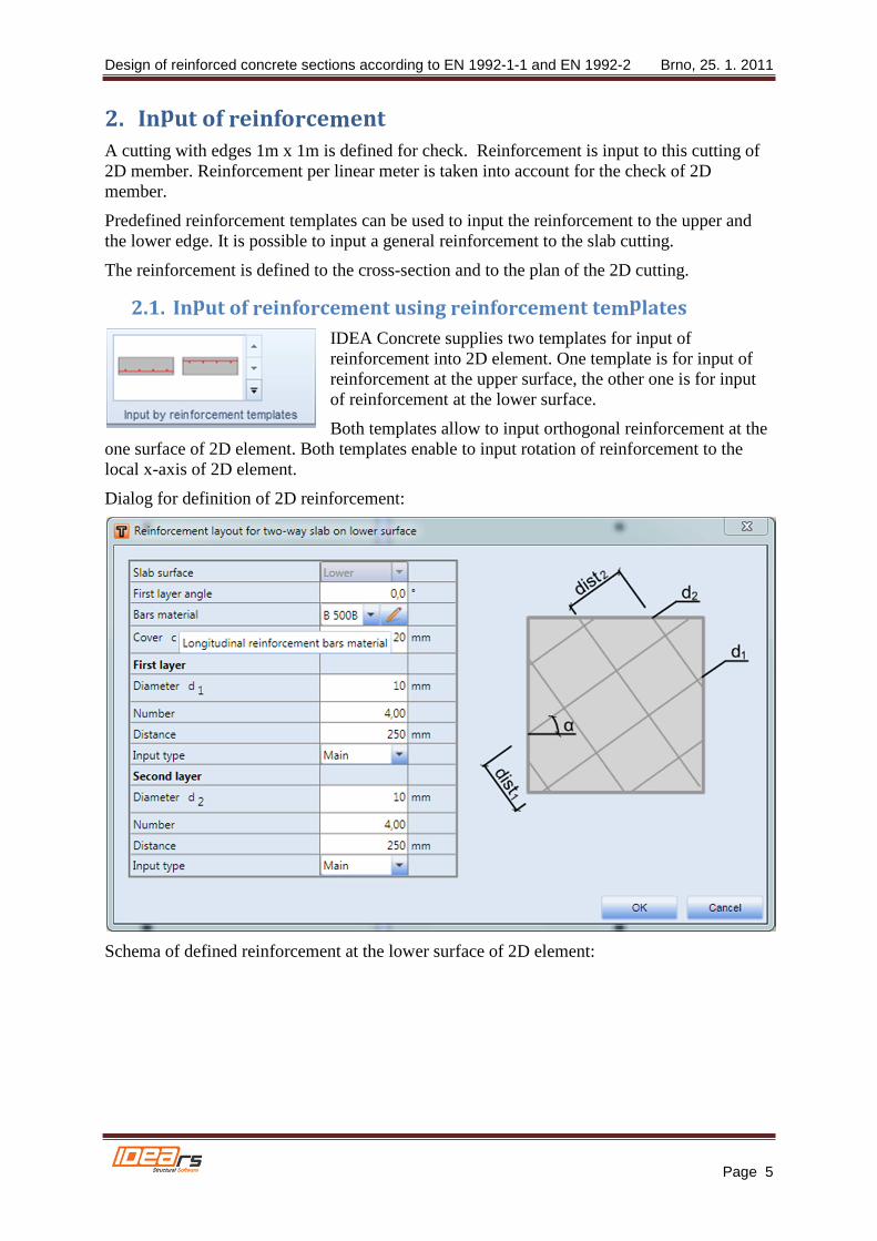
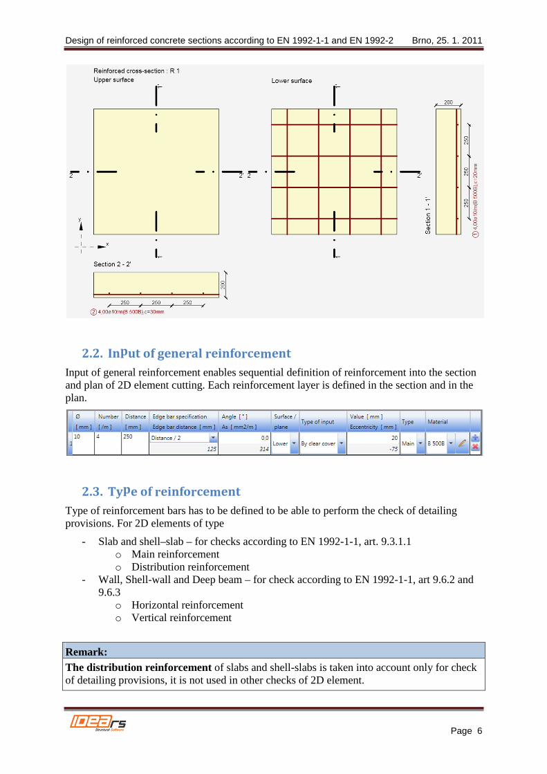
IDEA Concrete supplies two templates for input of reinforcement into 2D element. One template is for input of reinforcement at the upper surface, the other one is for input of reinforcement at the lower surface.
Both templates allow to input orthogonal reinforcement at the one surface of 2D element. Both templates enable to input rotation of reinforcement to the local x-axis of 2D element.
Dialog for definition of 2D reinforcement:
Schema of defined reinforcement at the lower surface of 2D element:
Design of reinforced concrete sections according to EN 1992-1-1 and EN 1992-2 Brno, 25. 1. 2011
Page 6
2.2. Input of general reinforcement
Input of general reinforcement enables sequential definition of reinforcement into the section and plan of 2D element cutting. Each reinforcement layer is defined in the section and in the plan.
2.3. Type of reinforcement
Type of reinforcement bars has to be defined to be able to perform the check of detailing provisions. For 2D elements of type
- Slab and shell–slab – for checks according to EN 1992-1-1, art. 9.3.1.1 o Main reinforcement o Distribution reinforcement
- Wall, Shell-wall and Deep beam – for check according to EN 1992-1-1, art 9.6.2 and 9.6.3
o Horizontal reinforcement o Vertical reinforcement
Remark: The distribution reinforcement of slabs and shell-slabs is taken into account only for check of detailing provisions, it is not used in other checks of 2D element.

Design of reinforced concrete sections according to EN 1992-1-1 and EN 1992-2 Brno, 25. 1. 2011
Page 7
3. Internal forces
3.1. Input of internal forces
Input of internal forces of 2D member depends on type of 2D element:
• Shell-slab – membrane forces (nx, ny and nxy), bending moments (mx, my and mxy) and shear forces (vx and vy) can be entered
• Shell- wall – membrane forces (nx, ny and nxy), bending moments (mx, my and mxy) and shear forces (vx and vy) can be entered
• Slab - only bending moments (mx, my and mxy) and shear forces (vx and vy) can be entered
• Wall – only membrane forces (nx, ny and nxy) can be entered • Deep beam - only membrane forces (nx, ny and nxy) can be entered
Description
mx(y) Bending moment in direction of x (y) axis. Positive value causes tension at the lower surface of 2D element.
mxy(yx) torsional moment about y (x)-axis acting on the edge parallel to the axis x (y). Positive value causes tensional shear stress at the lower surface of 2D element. Because in each point of 2D element theorem on equality of horizontal shear stresses is valid, torsional moments mxy = myx are equal in each point of 2D element too. Thus only value of mxy is entered in the program.
nx(y) Normal force in direction of x (y)-axis. Positive value acts in direction of x(y) axis and causes tension in section.
nxy(yx) Normal force acting in centre plane in direction of y(x)-axis on edge parallel to x(y) axis. Positive value acts in direction of x(y)-axis. Because in each point of 2D element theorem on equality of horizontal shear stresses is valid, normal forces nxy = nyx are equal in each point of 2D element too. Thus only value of nxy is entered in the program.
vx(y) Shear force acting perpendicular to centre plane on edge parallel to x(y)-axis. Positive value acts in direction of z-axis
Design of reinforced concrete sections according to EN 1992-1-1 and EN 1992-2 Brno, 25. 1. 2011
Page 8
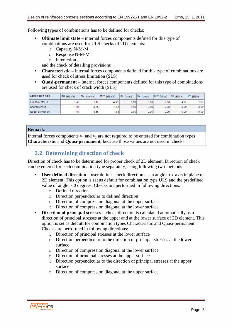
Following types of combinations has to be defined for checks:
• Ultimate limit state – internal forces components defined for this type of combinations are used for ULS checks of 2D elements:
o Capacity N-M-M o Response N-M-M o Interaction
and the check of detailing provisions • Characteristic – internal forces components defined for this type of combinations are
used for check of stress limitation (SLS) • Quasi-permanent – internal forces components defined for this type of combinations
are used for check of crack width (SLS)
Remark: Internal forces components vx and vy are not required to be entered for combination types Characteristic and Quasi-permanent, because those values are not used in checks.
3.2. Determining direction of check
Direction of check has to be determined for proper check of 2D element. Direction of check can be entered for each combination type separately, using following two methods:
• User defined direction – user defines check direction as an angle to x-axis in plane of 2D element. This option is set as default for combination type ULS and the predefined value of angle is 0 degrees. Checks are performed in following directions:
o Defined direction o Direction perpendicular to defined direction o Direction of compression diagonal at the upper surface o Direction of compression diagonal at the lower surface
• Direction of principal stresses – check direction is calculated automatically as a direction of principal stresses at the upper and at the lower surface of 2D element. This option is set as default for combination types Characteristic and Quasi-permanent. Checks are performed in following directions:
o Direction of principal stresses at the lower surface o Direction perpendicular to the direction of principal stresses at the lower
surface o Direction of compression diagonal at the lower surface o Direction of principal stresses at the upper surface o Direction perpendicular to the direction of principal stresses at the upper
surface o Direction of compression diagonal at the upper surface

Design of reinforced concrete sections according to EN 1992-1-1 and EN 1992-2 Brno, 25. 1. 2011
Page 9
3.2.1. Analysis of check direction for ultimate limit state
Analysis 1
For 2D element loaded only by bending moments (mx = 20 kNm/m, my = 10 kNm/m, mxy = 5 kNm/m ) angle of reinforcement and angle of check direction were changed for ultimate limit state. Results are displayed in following graph:
The analysis implies:
• If reinforcement bars are perpendicular to each other, check results are similar for different check direction angles, are not dependent on defined reinforcement angle and the maximal value of check is found for angles 0, 45 and 90 degrees. Thus check can be performed for predefined direction of check 0 degrees.
• If reinforcement bars are not perpendicular to each other, results of checks are different significantly and the maximal check value is achieved approximately in the direction corresponding with the direction of average reinforcement. Thus it is recommended to change predefined check direction or to perform checks in more directions in cases, when reinforcement bars are not perpendicular to each other.
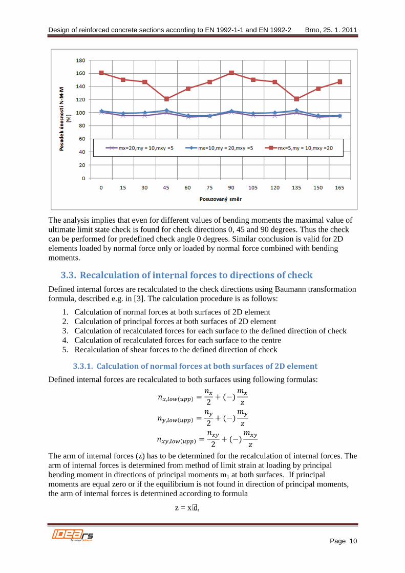
Analysis 2
For 2D element reinforced with rectangular reinforcement values of bending moments and angles for check were changed for ULS. Results are displayed in following graph:
Design of reinforced concrete sections according to EN 1992-1-1 and EN 1992-2 Brno, 25. 1. 2011
Page 10
The analysis implies that even for different values of bending moments the maximal value of ultimate limit state check is found for check directions 0, 45 and 90 degrees. Thus the check can be performed for predefined check angle 0 degrees. Similar conclusion is valid for 2D elements loaded by normal force only or loaded by normal force combined with bending moments.
3.3. Recalculation of internal forces to directions of check
Defined internal forces are recalculated to the check directions using Baumann transformation formula, described e.g. in [3]. The calculation procedure is as follows:
1. Calculation of normal forces at both surfaces of 2D element 2. Calculation of principal forces at both surfaces of 2D element 3. Calculation of recalculated forces for each surface to the defined direction of check 4. Calculation of recalculated forces for each surface to the centre 5. Recalculation of shear forces to the defined direction of check
3.3.1. Calculation of normal forces at both surfaces of 2D element
Defined internal forces are recalculated to both surfaces using following formulas:
��,������� � ��2 � �����
�,������� � �2 � ����
��,������� � ��2 � �����
The arm of internal forces (z) has to be determined for the recalculation of internal forces. The arm of internal forces is determined from method of limit strain at loading by principal bending moment in directions of principal moments m1 at both surfaces. If principal moments are equal zero or if the equilibrium is not found in direction of principal moments, the arm of internal forces is determined according to formula
z = x⋅d,
Design of reinforced concrete sections according to EN 1992-1-1 and EN 1992-2 Brno, 25. 1. 2011
Page 11
Description
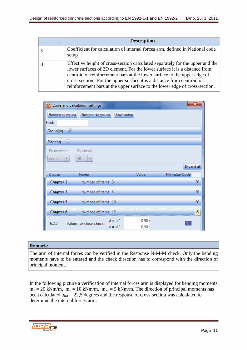
x Coefficient for calculation of internal forces arm, defined in National code setup.
d Effective height of cross-section calculated separately for the upper and the lower surfaces of 2D element. For the lower surface it is a distance from centroid of reinforcement bars at the lower surface to the upper edge of cross-section. For the upper surface it is a distance from centroid of reinforcement bars at the upper surface to the lower edge of cross-section.
Remark:
The arm of internal forces can be verified in the Response N-M-M check. Only the bending moments have to be entered and the check direction has to correspond with the direction of principal moment.
In the following picture a verification of internal forces arm is displayed for bending moments mx = 20 kNm/m, my = 10 kNm/m, mxy = 5 kNm/m. The direction of principal moments has been calculated αm1 = 22,5 degrees and the response of cross-section was calculated to determine the internal forces arm.

Design of reinforced concrete sections according to EN 1992-1-1 and EN 1992-2 Brno, 25. 1. 2011
Page 12
Remark: Internal forces arms for recalculation of internal forces to the direction of check and internal forces arms for checks can be different, because internal forces arm for recalculation is determined for cross-section loaded by principal moment in direction of principal moments, and the internal forces arm for check is determined for cross-section loaded by bending moments and normal forces in the direction of check. Values of internal forces arms for all combination types are displayed in the table Recalculated forces in the navigator Internal forces in section.
3.3.2. Calculation of internal forces at both surfaces
Principal forces at both surfaces of 2D element are calculated using formula
��,�� � �� � ��,���������,�������2 � 12� ��,���������,��������� � 4 ∙ ��,�������
��,�� � �� � ��,���������,�������2 � 12� ��,���������,��������� � 4 ∙ ��,�������
And the direction of principal forces is calculated using formula
Design of reinforced concrete sections according to EN 1992-1-1 and EN 1992-2 Brno, 25. 1. 2011
Page 13
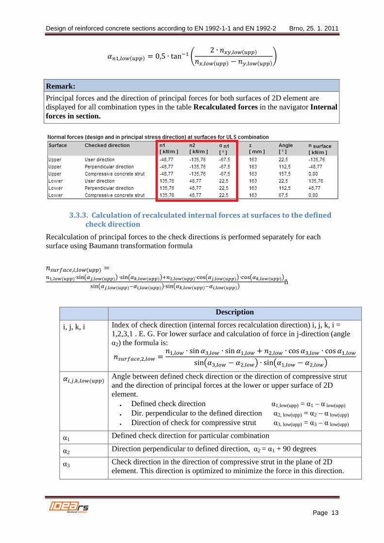
���,������� � 0,5 ∙ tan�� � 2 ∙ ��,���������,������� � �,��������
Remark:
Principal forces and the direction of principal forces for both surfaces of 2D element are displayed for all combination types in the table Recalculated forces in the navigator Internal forces in section.
3.3.3. Calculation of recalculated internal forces at surfaces to the defined
check direction
Recalculation of principal forces to the check directions is performed separately for each surface using Baumann transformation formula
��������,�,������� ���,�������∙�����,�������� ∙������,�����������,�������∙ !���,�������� ∙ !����,��������
�����,��������� ,��������∙������,��������� ,��������ň
Description
i, j, k, i Index of check direction (internal forces recalculation direction) i, j, k, i = 1,2,3,1 . E. G. For lower surface and calculation of force in j-direction (angle α2) the formula is:
��������,�,��� � ��,��� ∙ sin �",��� ∙ sin ��,��� � ��,��� ∙ cos �",��� ∙ cos ��,���
sin �",��� � ��,���� ∙ sin ��,��� � ��,����
��,#,$,������� Angle between defined check direction or the direction of compressive strut and the direction of principal forces at the lower or upper surface of 2D element.
• Defined check direction α1,low(upp) = α1 – α low(upp)
• Dir. perpendicular to the defined direction α2, low(upp) = α2 – α low(upp)
• Direction of check for compressive strut α3, low(upp) = α3 – α low(upp)
α1 Defined check direction for particular combination
α2 Direction perpendicular to defined direction, α2 = α1 + 90 degrees
α3 Check direction in the direction of compressive strut in the plane of 2D element. This direction is optimized to minimize the force in this direction.

Design of reinforced concrete sections according to EN 1992-1-1 and EN 1992-2 Brno, 25. 1. 2011
Page 14
Remark:
• If the check direction is identical with Principal stresses direction, the forces in compressive strut are zero, thus this direction is neglected in check
• The direction of compressive strut for all states of stress except the hyperbolic state of stress (n1,low(upp) > 0 and n1,low(upp) < 0) can be calculated according to formula: α3 = 0,5(α1 + α2)
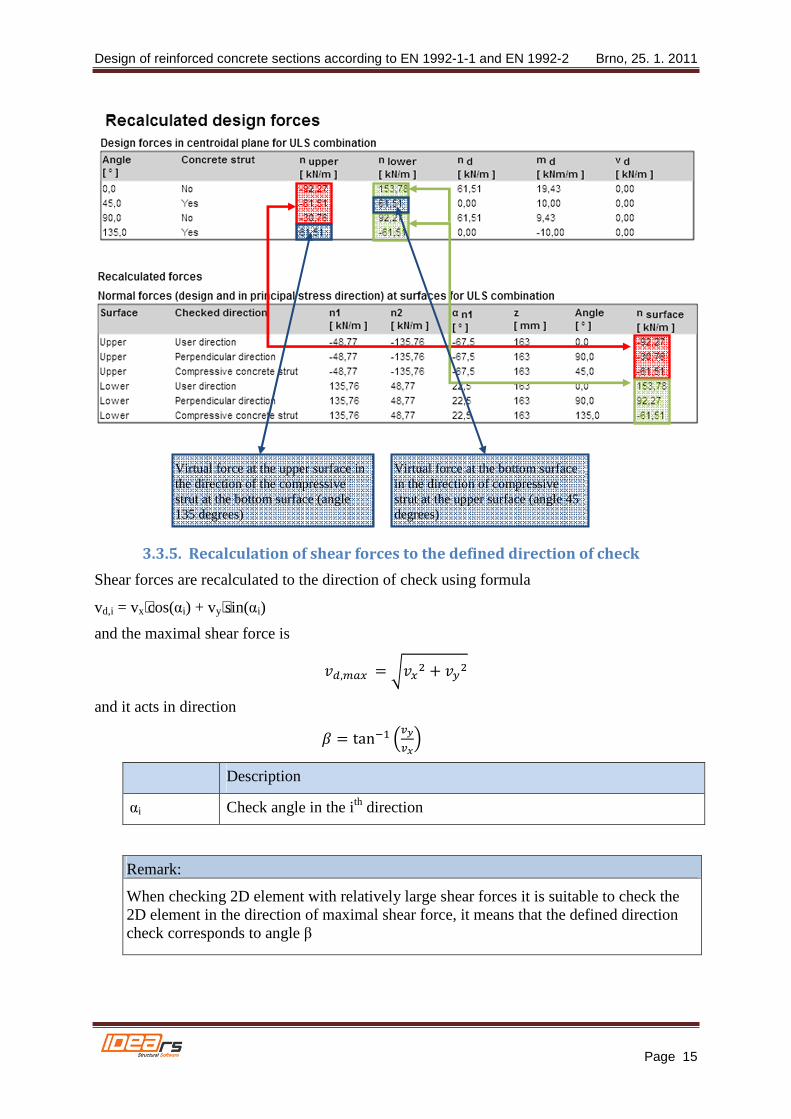
• Recalculated internal forces for both surfaces of 2D element a and all check directions including the direction of compressive strut are displayed in the table Recalculated forces
3.3.4. Transformation of recalculated internal forces to the centroid of
cross-section
For the check of 2D element the surface forces in particular direction have to be recalculated to the centroid of cross-section. The result is normal force nd,i and bending moment md,i acting in the centroid of the 2D element cross-section.
md,i = nlower,i·zs,low + nupper,i·zs,upp
nd,i = nlower,i + nupper,i
Description
nlower,i Recalculated surface forces at lower surface in the ith check direction, when nlower,i = nsurface,low,i.
nupper,i Recalculated internal forces at upper surface in the ith check direction, when nupper,i = nsurface,upp,i.
zs,low (upp) Distance of centroid of compressed concrete or centroid of reinforcement at the lower (upper) surface, when z = zs,low + zs,upp
Remark:
If the directions of compressive struts at the lower and the upper surface are different, for the recalculation of forces to the centroid it is necessary to calculate virtual forces at the bottom surface in the direction of compressive strut at the upper surface and vice versa.
Design of reinforced concrete sections according to EN 1992-1-1 and EN 1992-2 Brno, 25. 1. 2011
Page 15
3.3.5. Recalculation of shear forces to the defined direction of check
Shear forces are recalculated to the direction of check using formula
vd,i = vx⋅cos(αi) + vy⋅sin(αi)
and the maximal shear force is
�%,&�� � ���� � ��
and it acts in direction
� � tan�� (�(�!
Description
αi Check angle in the ith direction
Remark:
When checking 2D element with relatively large shear forces it is suitable to check the 2D element in the direction of maximal shear force, it means that the defined direction check corresponds to angle β
Virtual force at the bottom surface in the direction of compressive strut at the upper surface (angle 45 degrees)
Virtual force at the upper surface in the direction of the compressive strut at the bottom surface (angle 135 degrees)
Design of reinforced concrete sections according to EN 1992-1-1 and EN 1992-2 Brno, 25. 1. 2011
Page 16
3.4. Comparison of internal forces recalculation using various
methods
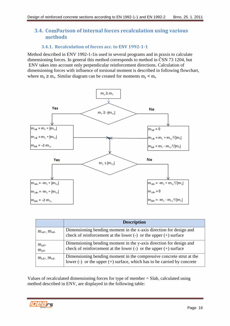
3.4.1. Recalculation of forces acc. to ENV 1992-1-1
Method described in ENV 1992-1-1is used in several programs and in praxis to calculate dimensioning forces. In general this method corresponds to method in ČSN 73 1204, but ENV takes into account only perpendicular reinforcement directions. Calculation of dimensioning forces with influence of torsional moment is described in following flowchart, where my ≥ mx. Similar diagram can be created for moments my < mx
Description
mxd+, mxd- Dimensioning bending moment in the x-axis direction for design and check of reinforcement at the lower (-) or the upper (+) surface
myd+
myd-
Dimensioning bending moment in the y-axis direction for design and check of reinforcement at the lower (-) or the upper (+) surface
mcd+, mcd- Dimensioning bending moment in the compressive concrete strut at the lower (-) or the upper (+) surface, which has to be carried by concrete
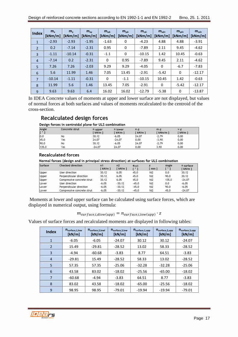
Values of recalculated dimensioning forces for type of member = Slab, calculated using method described in ENV, are displayed in the following table:
Design of reinforced concrete sections according to EN 1992-1-1 and EN 1992-2 Brno, 25. 1. 2011
Page 17
Index mx
[kNm/m]
my
[kNm/m]
mxy
[kNm/m]
mxd-
[kNm/m]
myd-
[kNm/m]
mcd-
[kNm/m]
mxd+
[kNm/m]
myd+
[kNm/m]
mcd+
[kNm/m]
1 -2.93 -2.93 -1.95 -1.63 0 -4.23 4.88 4.88 -3.91
2 0.2 -7.14 -2.31 0.95 0 -7.89 2.11 9.45 -4.62
3 -1.11 -10.14 -0.31 -1.1 0 -10.15 1.42 10.45 -0.63
4 -7.14 0.2 -2.31 0 0.95 -7.89 9.45 2.11 -4.62
5 7.26 7.26 -2.03 9.29 9.29 -4.05 0 -6.7 -7.83
6 5.6 11.99 1.46 7.05 13.45 -2.91 -5.42 0 -12.17
7 -10.14 -1.11 -0.31 0 -1.1 -10.15 10.45 1.42 -0.63
8 11.99 5.6 1.46 13.45 7.05 -2.91 0 -5.42 -12.17
9 9.63 9.63 6.4 16.02 16.02 -12.79 -5.38 0 -13.87
In IDEA Concrete values of moments at upper and lower surface are not displayed, but values of normal forces at both surfaces and values of moments recalculated to the centroid of the cross-section.
Moments at lower and upper surface can be calculated using surface forces, which are displayed in numerical output, using formula:
��������,�,%������� � ��������,�,������� ∙
Values of surface forces and recalculated moments are displayed in following tables:
Index nsurface,1,low
[kN/m]
nsurface,2,lowl
[kN/m]
nsurface,3,low
[kN/m]
nsurface,1,upp
[kN/m]
nsurface,2,upp
[kN/m]
nsurface,3,upp
[kN/m]
1 -6.05 -6.05 -24.07 30.12 30.12 -24.07
2 15.49 -29.81 -28.52 13.02 58.33 -28.52
3 -4.94 -60.68 -3.83 8.77 64.51 -3.83
4 -29.81 15.49 -28.52 58.33 13.02 -28.52
5 57.35 57.35 -25.06 -32.28 -32.28 -25.06
6 43.58 83.02 -18.02 -25.56 -65.00 -18.02
7 -60.68 -4.94 -3.83 64.51 8.77 -3.83
8 83.02 43.58 -18.02 -65.00 -25.56 -18.02
9 98.95 98.95 -79.01 -19.94 -19.94 -79.01
Design of reinforced concrete sections according to EN 1992-1-1 and EN 1992-2 Brno, 25. 1. 2011
Page 18
Index
msurface,1,low
(mxd-)
[kNm/m]
msurface,2,low
(myd-)
[kNm/m]
msurface,3,low
(mcd-)
[kNm/m]
msurface,1,upp
(mxd+-)
[kNm/m]
msurface,1,upp
(myd+)
[kNm/m]
msurface,1,upp
(mcd+)
[kNm/m]
1 -0.98 -0.98 -3.90 4.88 4.88 -3.90
2 2.51 -4.83 -4.62 2.11 9.45 -4.62
3 -0.80 -9.83 -0.62 1.42 10.45 -0.62
4 -4.83 2.51 -4.62 9.45 2.11 -4.62
5 9.29 9.29 -4.06 -5.23 -5.23 -4.06
6 7.06 13.45 -2.92 -4.14 -10.53 -2.92
7 -9.83 -0.80 -0.62 10.45 1.42 -0.62
8 13.45 7.06 -2.92 -10.53 -4.14 -2.92
9 16.03 16.03 -12.80 -3.23 -3.23 -12.80
The table show, that moments at slab surfaces calculated in IDEA Concrete and calculated according to method described in ENV, correspond only at one surface. This difference is caused by different optimisation of concrete strut. Method used in IDEA Concrete searches for the angle of compressive strut at the minimal force in the strut. The method described in ENV searches for minimal sum of negative forces from all directions.
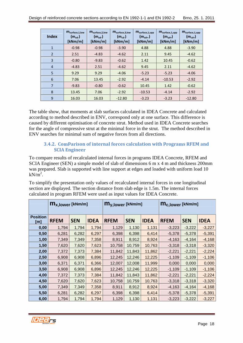
3.4.2. Comparison of internal forces calculation with programs RFEM and
SCIA Engineer
To compare results of recalculated internal forces in programs IDEA Concrete, RFEM and SCIA Engineer (SEN) a simple model of slab of dimensions 6 m x 4 m and thickness 200mm was prepared. Slab is supported with line support at edges and loaded with uniform load 10 kN/m2.
To simplify the presentation only values of recalculated internal forces in one longitudinal section are displayed. The section distance from slab edge is 1.5m. The internal forces calculated in program RFEM were used as input values for IDEA Concrete.
mx,lower [kNm/m]
my,lower [kNm/m]
mc,lower [kNm/m]
Position [m] RFEM SEN IDEA RFEM SEN IDEA RFEM SEN IDEA
0,00 1,794 1,794 1,794 1,129 1,130 1,131 -3,223 -3,222 -3,227
0,50 6,281 6,282 6,297 6,398 6,398 6,414 -5,378 -5,378 -5,391
1,00 7,349 7,349 7,358 8,911 8,912 8,924 -4,163 -4,164 -4,168
1,50 7,620 7,620 7,623 10,758 10,759 10,763 -3,318 -3,318 -3,320
2,00 7,372 7,373 7,384 11,842 11,843 11,862 -2,221 -2,221 -2,224
2,50 6,908 6,908 6,896 12,245 12,246 12,225 -1,109 -1,109 -1,106
3,00 6,371 6,371 6,366 12,007 12,008 11,999 0,000 0,000 0,000
3,50 6,908 6,908 6,896 12,245 12,246 12,225 -1,109 -1,109 -1,106
4,00 7,372 7,373 7,384 11,842 11,843 11,862 -2,221 -2,221 -2,224
4,50 7,620 7,620 7,623 10,758 10,759 10,763 -3,318 -3,318 -3,320
5,00 7,349 7,349 7,358 8,911 8,912 8,924 -4,163 -4,164 -4,168
5,50 6,281 6,282 6,297 6,398 6,398 6,414 -5,378 -5,378 -5,391
6,00 1,794 1,794 1,794 1,129 1,130 1,131 -3,223 -3,222 -3,227
Design of reinforced concrete sections according to EN 1992-1-1 and EN 1992-2 Brno, 25. 1. 2011
Page 19
The table shows good compliance of forces calculated in particular programs.
4. Check
As described in 3.3.4 Transformation of recalculated internal forces to the centroid of cross-section, surface dimensioning forces are transformed to the centroid of 2D element cross-section. The result of this transformation is bending moment and normal force, acting in the centroid of rectangular cross-section, which edge length is 1m and height corresponds to the thickness of the slab.
The checks of 2D element are performed in all defined directions at once. The program automatically converts the reinforcement to the check direction using formula
Asi,α = As ⋅ cos2(αi)
Description
Asi,α The area of the ith reinforcement layer recalculated to the direction α
As The area of the ith reinforcement layer of 2D element
αi The angle between ith reinforcement layer and the check direction
Remark: Distributive reinforcement in 2D elements of type slab and shell-slab is taken into account only in detailing provision check, it is not used in other 2D element checks.
4.1. Results of check in defined directions
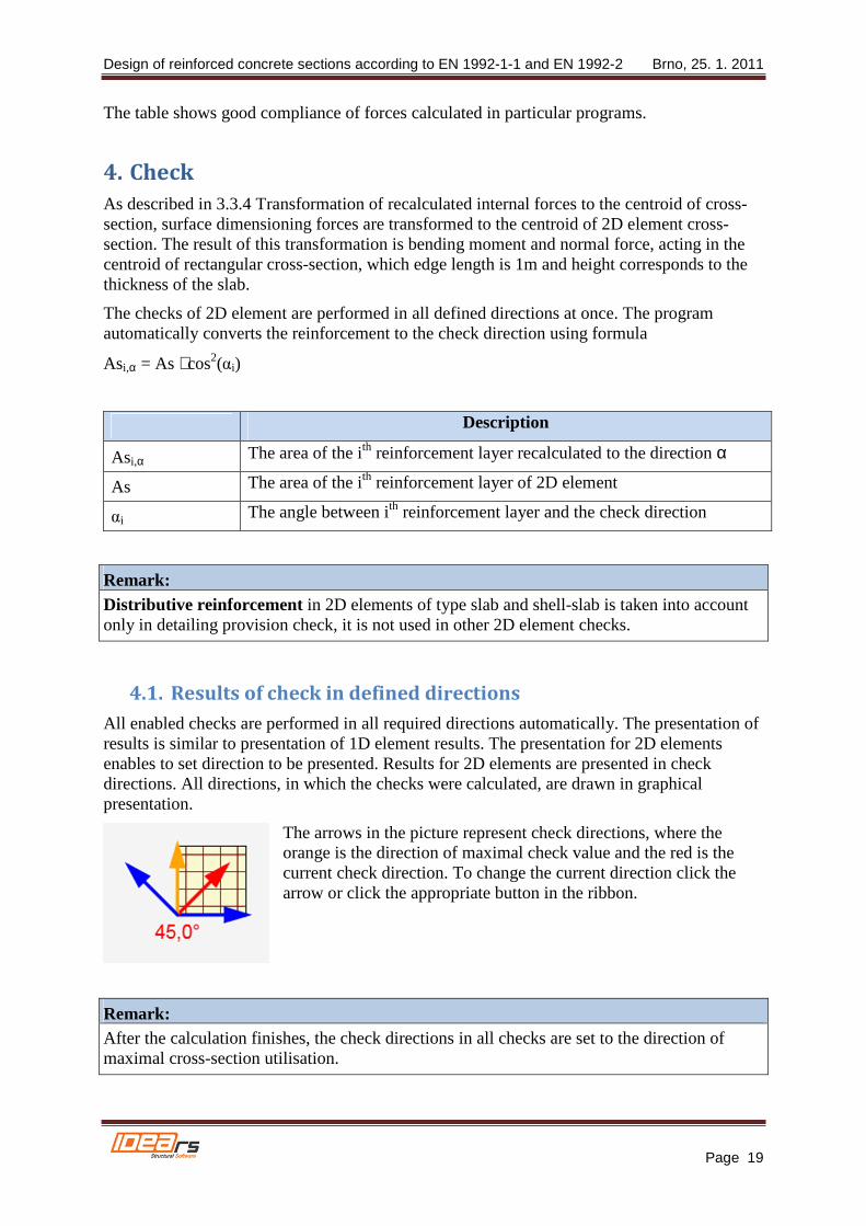
All enabled checks are performed in all required directions automatically. The presentation of results is similar to presentation of 1D element results. The presentation for 2D elements enables to set direction to be presented. Results for 2D elements are presented in check directions. All directions, in which the checks were calculated, are drawn in graphical presentation.
The arrows in the picture represent check directions, where the orange is the direction of maximal check value and the red is the current check direction. To change the current direction click the arrow or click the appropriate button in the ribbon.
Remark: After the calculation finishes, the check directions in all checks are set to the direction of maximal cross-section utilisation.

Design of reinforced concrete sections according to EN 1992-1-1 and EN 1992-2 Brno, 25. 1. 2011
Page 20
Results in particular checks are presented in the current direction. The angle of check is displayed above the table with the check summary.
The results in the extreme direction are printed in report.
4.2. Ultimate limit state
The principles of ULS checks are described in theoretical background manual for 1D elements. Only the differences for 2D elements are described in following chapters.
4.2.1. Capacity check
The capacity check does not differ from 1D elements checks. The load acts only in one plane, thus the check type is N + M.
4.2.2. Response check
The response checks for particular check directions use the same algorithms as checks of 1D elements.
4.2.3. Interaction check
Unlike for 1D elements, the interaction check is performed only to evaluate the exploitation V + M, the interaction of shear and bending moment. The separate shear check is not performed in current version. Values VRd,c and VRd,max can be verified in summary table of the interaction check.
4.2.4. Capacity check comparison between IDEA Concrete, RFEM and SCIA
Engineer
To compare the capacity check results with RFEM and SCIA Engineer the same data as described in chapter 3.4.2 Comparison of internal forces calculation with programs RFEM and SCIA Engineer were used. The comparison was done in two points of slab.
Because programs RFEM and SEN do not check the real reinforcement in the slab, but only design the necessary reinforcement area, two methods were used to compare the calculation. The first one compares the exploitation of cross-section for required reinforcement designed in RFEM and SEN, assuming that the cross-section is exploited to 100% just when using the calculated required area of reinforcement.
The exploitation of cross-section reinforced in IDEA concrete can be expressed relatively then.
Relative exploitation = As, req / As, RCS ⋅ 100 [%]
Description
As, req Required reinforcement area calculated in RFEM or SEN
As, RCS Area of reinforcement in IDEA Concrete
100 [%] Percentage

Design of reinforced concrete sections according to EN 1992-1-1 and EN 1992-2 Brno, 25. 1. 2011
Page 21
The cross-section in IDEA Concrete was reinforced at the lower surface using reinforcement φ10 in 200 mm distances in both directions, the area of reinforcement in both directions is 314 mm2.
Comparison results are in the following table:
Position Direction
Reinforcement area
As [mm2]
Cross-section exploitation
[%]
Relative
exploitation [%]
X Y RFEM SEN IDEA RFEM SEN IDEA RFEM SEN
0,5 0,5 x lower 116 123 314 100 100 37 37 39
0,5 0,5 y lower 129 137 314 100 100 39 41 44
3,0 2,0 x lower 87 93 314 100 100 29 28 30
3,0 2,0 y lower 174 183 314 100 100 58 55 58
The table shows good compliance of exploitation for all programs.
The reinforcement with the approximately same area was defined in IDEA Concrete as calculated required reinforcement in RFEM and SEN for the second method. Afterwards the exploitation of cross-section was compared. Results are displayed in following table:
Position Direction Reinforcement area As [mm2]
Cross-section exploitation
[%]
X Y RFEM SEN IDEA RFEM SEN IDEA
0,5 0,5 x lower 116 123 φ10 / 650mm2 123 100 100 103
0,5 0,5 y lower 129 137 φ 10 / 600mm2 137 100 100 94
3 2 x lower 87 93 φ 10 / 800mm2 93 100 100 103
3 2 y lower 174 183 φ 10 / 450mm2 183 100 100 93
The good compliance of results is here too.
4.3. Serviceability limit state
4.3.1. Stress limitation
Check of stress limitation does not differ from checks for 1D elements.
4.3.2. Crack width check
In advance to 1D elements check the direction of crack can be drawn for 2D elements.
4.4. Detailing provisions
Detailing provisions check of 2D elements can be split into two basic groups:
- Reinforcement percentage check - Bar distances check

Design of reinforced concrete sections according to EN 1992-1-1 and EN 1992-2 Brno, 25. 1. 2011
Page 22
The detailing provisions check depends on type of 2D element too. The separate checks for the main and for the distribution reinforcement are performed for shell-slab and slab elements. The vertical and horizontal reinforcement is distinguished for wall elements.
The reinforcement percentage check is performed in the direction of principal stresses. The reinforcement defined in cutting of 2D element (except the distribution reinforcement) is transformed to the principal stresses directions.
The bars distance check is performed perpendicular to the direction of defined reinforcement. This check is performed for all defined reinforcement layers and the limit values depend on the type of checked element and on the type of defined reinforcement.

Design of reinforced concrete sections according to EN 1992-1-1 and EN 1992-2 Brno, 25. 1. 2011
Page 23
5. Literature
[1] EN 1992-1-1: 2004 Eurocode 2 : design of concrete structures – Part 1: General rules and rules for building
[2] ENV 1992-1-1: 1991 Eurocode 2 : design of concrete structures – Part 1: General rules and rules for building
[3] Baumann, Th. : "Zur Frage der Netzbewehrung von Flächentragwerken".
In : Der Bauingenieur 47 (1972), Berlin 1975