design of progressively folding thin-walled tubular
TRANSCRIPT

Design of Progressively Folding Thin-Walled Tubular
Components Using Compliant Mechanism Synthesis
Punit Bandia, Duane Detwilerb, James P. Schmiedelerc, Andres Tovard,∗
aGeneral Motors Company, Detroit, Michigan, 48232bHonda R&D Americas, Raymond, Ohio 43067
cUniversity of Notre Dame, Notre Dame, Indiana, 46556dIndiana University-Purdue University Indianapolis, Indianapolis, Indiana, 46202
Abstract
This work introduces a design method for the progressive collapse of thin-walled tubular components under axial and oblique impacts. The proposeddesign method follows the principles of topometry optimization for compliantmechanism design in which the output port location and direction determinethe folding (collapse) mode. In this work, the output ports are located nearthe impact end with a direction that is perpendicular to the component’slongitudinal axis. The topometry optimization is achieved with the use ofhybrid cellular automata for thin-wall structures. The result is a complexenforced buckle zone design that acts as a triggering mechanism to (a) initi-ate a specific collapse mode from the impact end, (b) stabilize the collapseprocess, and (c) reduce the peak force. The enforced buckle zone in the endportion of the tube also helps to avoid or delay the onset of global bend-ing during an oblique impact with load angles higher than a critical value,which otherwise adversely affects the structure’s capacity for load-carryingand energy absorption. The proposed design method has the potential todramatically improve thin-walled component crashworthiness.
Keywords: Thin-walled square tubes, progressive buckling, compliantmechanisms, topometry design, structural optimization, hybrid cellularautomata
∗Corresponding Author
Preprint submitted to Thin-Walled Structures June 20, 2015
This is the author's manuscript of the article published in final edited form as: Bandi, P., Detwiler, D., Schmiedeler, J. P., & Tovar, A. (2015). Design of progressively folding thin-walled tubular components using compliant mechanism synthesis. Thin-Walled Structures, 95, 208-220.http://dx.doi.org/10.1016/j.tws.2015.06.010

1. Introduction
Thin-walled tubular components are extensively used as structural mem-bers in the majority of transportation vehicles because of their low cost, goodenergy absorption capability, and relatively low density. They have the abil-ity to absorb the kinetic energy of the impacting body in the form of plasticdeformation, hence protecting the structure and passengers involved. Thesestructures can be used in various loading conditions such as axial crushing,bending, oblique impact, and transverse loading. Tubular structures showsignificant energy absorption for long strokes in an axial crushing mode and,therefore, present an attractive option in crashworthiness designs.
A great deal of research has been done to study the axial crushing ofthin-walled tubes since the pioneering work of Pugsley [1] and Alexander [2]during the 1960s. In the 1980s, work on both the static and dynamic re-sponses of tubes focused more on theoretical and experimental studies [3, 4].The concept of a superfolding element was introduced by Wierzbicki andAbramowicz [5] to better understand the crushing mechanics of thin-walledstructures. With the advancement in computing power and the numericalimplementation of finite element methods in the last two decades, consid-erable work has been done to create equivalent numerical models for tubecrushing and their validation with experimental tests [6, 7, 8, 9]. With thehelp of advanced nonlinear software like LS-DYNA and ABAQUS, resultsfrom numerical models of axial and oblique loadings of thin-walled struc-tures sufficiently match experimental results.
Various experimental and numerical studies revealed three dominant modesof deformation during the axial crushing of thin-walled structures: progres-sive buckling, global or Euler-type buckling, and dynamic plastic buckling[10]. Of these three, the progressive buckling mode is desired for crash-worthy designs because of its efficient energy absorption and better force-displacement behavior. In progressive buckling, crushing starting at one end(often the end close to the impact) and progressing systematically toward theother end of the structure is preferred since it utilizes the maximum possi-ble material for plastic deformation without jamming. Also, the progressivebuckling from the front end to the back end helps to protect important com-ponents close to or behind these energy absorbing structures. For example,the damage for low intensity (∼ 7-10 mph) frontal impacts in automobilescan be restricted to the bumper-beam and crash-box (hence saving the frontframe-rail behind them) if the crash-box collapses progressively without jam-
2

(a) Undeformed (b) At 0.01 sec (c) At 0.1 sec
Figure 1: Progressive collapse of a thin-walled tubular component with a geometric im-perfection (blue stripe) under axial crushing load by a rigid plate.
ming. Thin-walled square tubes, however, do not buckle progressively fromthe front end to the back end in all cases. The buckling behavior is depen-dent on many factors such as loading conditions, geometry, imperfections,and asymmetries in the structure. For example, Fig. 1 shows the deforma-tion under axial compression of a tube of uniform thickness (1 mm) exceptfor a small imperfection in the form of a patch (blue stripe) of thickness 0.8mm. It can be seen that buckling starts at the location of the imperfectionand then progresses in both directions. Interestingly, for this model, eventhough the imperfection is located in one single face, the initial progressivebuckling mode is extensional; in other words, the four collapse elements (oneper face) “extend” outwards (see Sec. 2).
Collapse initiators, also known as triggers, stress concentrators, or imper-fections, can be used to initiate a specific axial collapse mode, stabilize thecollapse process, and reduce the peak force during the axial crush [11, 12, 13].Researchers have proposed ways of introducing buckle initiators or surfacepatterns to enhance energy absorption and buckling behavior by introducingvarious crush zones in the structure in the form of chamfering [14], dents[15], multi-corners [16], multi-cells [17, 18], diamond notches and holes [19],triggering dents, circumferential grooves and stiffeners [20]. The use of col-
3

lapse initiators has been demonstrated to reduce sensitivity to geometric andmaterial imperfections, reduce peak crushing force, and increase energy ab-sorption density; however, its effectiveness largely depends on the directionof the load and the general shape of the component. An overview of tech-niques using geometric and material modifications to improve the bucklingbehavior and energy absorption characteristics of thin-walled tubes underaxial crushing can be found in a review article by Yuen and Nurick [21].
During an actual crash event, the tubular structure will seldom be sub-jected to pure axial loads. Thin-walled structures are subjected to both axialforces and bending moments in an oblique crash. During the study of thin-walled tubes under oblique impacts, Han and Park [22] and Reyes et al. [23]observed a phenomenon of the onset of global bending or Euler-type bucklingif the load angle was higher than a critical value. This onset of global bendingseverely reduces the energy absorption capability of tubular component.
In the methodology presented here, thickness-based (topometry) design[24] is extended to thin-walled square tubes under axial compression usingcompliant mechanism synthesis [25]. The ability of compliant mechanismsto transfer motion and forces from an input load location to the desiredpoints in the structure is utilized to achieve the desired buckle zones in theaxial member. By suitably defining the output port locations and desireddisplacement directions, progressive buckling can be initiated at the desiredlocations. Moreover, using this method, thin-walled structures can be de-signed to show progressive buckling even in cases of oblique impact at angleshigher than the critical value at which bending collapse dominates the axialcollapse and leads to poor energy absorption. To perform thickness-basedtopometry design of mechanisms, the structural synthesis method for com-pliant mechanism of Bandi et al. [25] is modified by using thickness as thedesign variable. In the following sections, a detailed description of the pro-posed method and two illustrative examples are presented.
2. Progressive Buckling in Square Tubes
During pure axial crushing of a thin-walled tubular component, the max-imum peak force (Fmax) appears when the structure starts buckling for thefirst time, and after that, the force oscillates between local peaks and minimaas shown in Fig. 2. Each pair of peaks is associated with the developmentof a wrinkle or buckle. Usually, these wrinkles or buckles develop sequen-tially from one end of a tube so that the phenomenon is known as progressive
4
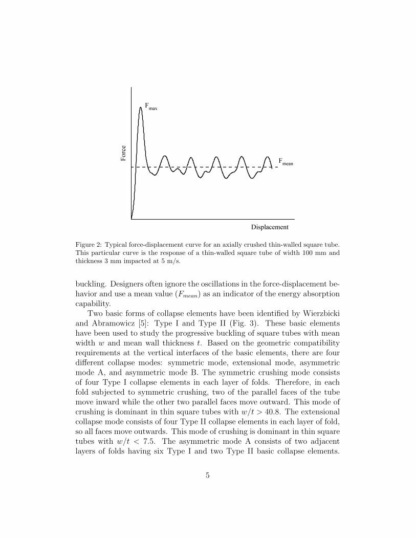
Figure 2: Typical force-displacement curve for an axially crushed thin-walled square tube.This particular curve is the response of a thin-walled square tube of width 100 mm andthickness 3 mm impacted at 5 m/s.
buckling. Designers often ignore the oscillations in the force-displacement be-havior and use a mean value (Fmean) as an indicator of the energy absorptioncapability.
Two basic forms of collapse elements have been identified by Wierzbickiand Abramowicz [5]: Type I and Type II (Fig. 3). These basic elementshave been used to study the progressive buckling of square tubes with meanwidth w and mean wall thickness t. Based on the geometric compatibilityrequirements at the vertical interfaces of the basic elements, there are fourdifferent collapse modes: symmetric mode, extensional mode, asymmetricmode A, and asymmetric mode B. The symmetric crushing mode consistsof four Type I collapse elements in each layer of folds. Therefore, in eachfold subjected to symmetric crushing, two of the parallel faces of the tubemove inward while the other two parallel faces move outward. This mode ofcrushing is dominant in thin square tubes with w/t > 40.8. The extensionalcollapse mode consists of four Type II collapse elements in each layer of fold,so all faces move outwards. This mode of crushing is dominant in thin squaretubes with w/t < 7.5. The asymmetric mode A consists of two adjacentlayers of folds having six Type I and two Type II basic collapse elements.
5

The asymmetric mode B consists of two adjacent layers of folds having sevenType I and one Type II basic collapse elements. Asymmetric modes A andB are predicted to take place within the range 7.5 < w/t < 40.8. In thepresent work, tubes are designed to promote a symmetric mode of collapseby defining output ports on the two parallel faces pointing inward.
w/2 w/2
w/2 w/2
(a) (b)
Figure 3: Basic collapse element shapes for a quarter of a square cross section of a tubewith width w: (a) Type I and (b) Type II.
3. Compliant Mechanism Design in Topology Optimization
The objective of a compliant mechanism is to efficiently transfer forces andmotion from an input actuation location (referred to as input port) to desiredoutput locations (referred to as output ports) in a structure. In the design ofa compliant mechanism, there are no restrictions on the locations of the ports;however, input and output ports typically correspond to separate points (orset of points) in the structure’s boundary. The related optimization problemis to find the optimal material distribution that maximizes the displacementat the output ports subjected to a mass equality constraint [26, 27]. Thedisplacement at an output port dout can be represented in an energy-likefunctional quantity known as mutual potential energy (MPE) [28, 29]. Thisis
dout ≡MPE = FTdD1 =
∫Ω
σTd ε dΩ, (1)
where Fd can be thought of as the vector of “dummy” or fictitious forces ofunit magnitude acting at the output port in the direction of the desired out-put displacement and D1 is the vector of nodal displacements resulting from
6

the input load. Notably, the dummy loads are applied at the output portswhile the input displacements are obtained at the input ports. Similarly, σd
is the stress field due to the dummy load, and ε is the strain field due to theinput load. Dummy loads are not physical. In compliant mechanism design,they are used as an alternative way to express output port displacement interms of an energy functional quantity such as MPE. This enables separationof local energy contributions from individual elements. Hence, the optimiza-tion problem of maximizing the output port displacement subject to a massequality constraint can be written as
find x ∈ Rn
minimize −MPE(x)subject to 1
n
∑ni=1 xi = M∗
f
0 < xmin ≤ xi ≤ 1 for i = 1, . . . , n,
(2)
where xi is the design variable that characterizes the material property of theelement of the structure at the discrete location i. In the context of topologyoptimization, xi is referred to as an “artificial” or relative material density[27]. In particular, xi = (Ei/E0)1/p, where E0 is the Young’s modulus of thematerial, Ei is its interpolated value, and p is a penalization factor usuallyselected to be p = 3. M∗
f represents the target mass fraction correspondingto the sum of the element masses with unit volume.
To calculate the MPE, a dummy load method is used in which two loadcases are considered [29]. In the first load case, an input force at the inputports is applied. In the second load case, a unit dummy load is applied at theoutput port in the direction of the desired displacement. The MPE is definedbased on these two load cases, and Eq. (1) is then used to determine the work(response) of the input loads at the output port locations. The optimizationalgorithm incorporated in this work is the hybrid cellular automata (HCA)algorithm originally proposed by Tovar et al. [30]. The HCA algorithm is anapproach inspired by the bone functional adaptation process in which localevolutionary rules, obtained from classical control theory, iteratively establishthe value of the design variables (or cellular automata) that minimize thelocal error between a so-called field variable and a corresponding set point.The expression for the field variable and the set point are derived from theproblem’s Karush-Kuhn-Tucker (KKT) optimality conditions [31]. The HCAalgorithm has been extended to design non-linear compliant mechanisms byBandi et al. [25, 32].
7

v0
dout1 dout1
constrained
dout2 dout2
dout3 dout3
Buckle
zones
(a) (b)
Figure 4: Three sets of output ports, pointing inward, defined on the two parallel faces totrigger buckling. (a) Front view showing the impacting wall at a velocity v0. (b) Isometricview of the output ports (enforced buckle zones) in one of the parallel faces.
4. Methodology
Using the proposed compliant mechanism method, thin-walled squaretubes can be designed to undergo progressive buckling starting from the frontend during axial crushing regardless of geometric and material imperfections,asymmetries in the tube geometry, and loading conditions. The underlyingprinciple is to design the tube using a compliant mechanism approach totrigger the symmetric mode of collapse near the impact end. Figure 4 showsthree sets of inward-pointing output ports on two parallel faces of the squaretube. The deformation is initiated at these ports in the pointing directionand, hence, forms a fold or wrinkle with four Type I elements per layer (threelayers in this case). The location of the output ports along the length of thetube is referred to as the “enforced buckle zone” in subsequent discussions.
The compliant mechanism design approach described in Section 3 is mod-ified to perform thickness-based (topometry) design changes. For plane stresselements, the variation in relative density and thickness has the same effecton the element stiffness tensor [27]. Since plane stress shell elements areused to model thin-walled structures, relative density x can be replaced by
8

the element thickness t in the compliant mechanism problem formulation as
find t ∈ Rn
minimize −MPE(t),subject to 1
n
∑ni=1 ti = T ∗,
0 < tmin ≤ ti ≤ tmax for i = 1, . . . , n.
(3)
The original mass equality constraint is reformulated as an equality con-straint on the average thickness value. The dummy load method is used toevaluate mutual potential energy (MPE) with the help of two load cases (seeSec. 3). In the first load case, the dynamic axial crushing caused by therigid plate is approximated by static axial loads, while in the second loadcase, a dummy load Fd is applied at the output ports in the direction of thedesired displacement. Here again the HCA algorithm is used to solve the op-timization problem. Once the tube is designed to transfer motion and forcesfrom the input loading points to the prescribed output points efficiently withthe approximated static loading, it will behave in a similar fashion with theapplication of actual dynamic loading. The enforced buckle zones act astriggering mechanisms and help to reduce the peak force by facilitating theformation of folds with less resistance. In addition, these enforced bucklezones delay or completely eliminate the onset of global bending (Euler-typebuckling) during oblique impacts with load angles higher than the criticalvalue.
5. Examples
In the following two examples, the explicit nonlinear finite element codeLS-DYNA is used to perform dynamic simulations of axial crushing of squaretubes. A linear elastic, piecewise linear plastic material (*MAT24) is usedfor modeling steel tubes with properties shown in Table 1.
Generally, thin-walled structures under axial compression are modeledwith plane stress shell elements. In several investigations [33, 7], reasonableagreement has been found between shell-based finite element simulationsand experimental results. This work models tubes using a very efficientplane stress shell element formulation from LS-DYNA (ELFORM=16) thatis not subject to hourglassing (spurious strain energy modes) due to fourin-plane integration points. Five integration points are used throughout thethickness in order to capture the local element bending accurately. Thiselement is a fully integrated shell with assumed strain interpolants used to
9

Table 1: MATERIAL PROPERTIES OF STEEL USED FOR MODELING SQUARETUBES
Property ValueDensity 7800 kg/m3
Elastic Modulus 207 GPaPoisson’s Ratio 0.29Yield Stress 253 MPa
Effective plastic Effective stressstrain (MPa)0.000 2530.048 3670.108 4200.148 4420.208 4680.407 5240.607 5610.987 608
alleviate locking and enhance in-plane bending behavior [34]. Fracture is notconsidered in this analysis.
The examples in this section consider thin-walled structures of high width-to-thickness ratio, w/t > 40.8, which are commonly found in automotiveapplications. The design process is performed on structures that are freeof geometric and material imperfections and are subjected to axial loading.The reason is that the exact features of the imperfections and the directionof the load are unknown. Hence, the idea of the present work is to obtain adesign that behaves in a desired predictable manner even in the presence ofunexpected imperfections and/or oblique impact.
5.1. Progressive Buckling in the Presence of an Imperfection
This example considers the axial crushing with a rigid flat plate of a thin-walled square tube constrained at one end. The tube is 200 mm long, andthe square cross section is 50 mm wide. The tube has a uniform thicknessof 1 mm, except an imperfection is added in the form of a small patch (4mm long) of thickness 0.8 mm in the middle of one face. The schematicof the tube and the location of the imperfection are shown in Fig. 5 (alldimensions are in mm.). The rigid plate, which has a mass of 147 kg, isgiven an initial velocity v0 (3, 5 and 10 m/s). The contact between therigid plate and the tube is modeled using a constraint algorithm (*CON-TACT AUTOMATIC NODES TO SURFACE) with a friction coefficient of0.3 to allow sliding movement. To account for the contact between the lobes(folds) during deformation, a single surface contact algorithm with a coeffi-
10

cient of friction 0.1 is used [35].
8
104
4
v0 Rigid Plate
Imperfection
Constrained
Figure 5: Schematic of a thin-walled square tube with an imperfection impacted axiallyby a rigid plate.
A mesh convergence study is performed with various mesh refinementsand two values of initial velocity v0 for the impacting rigid plate. The force-displacement behavior, amount of energy absorption, and lobe (fold) forma-tion pattern are used to evaluate the mesh size sufficiency. Depending onthe mesh size, a single-precision dynamic crush simulation takes between 2and 10 hours on LS-DYNA V971 R6.1.2 (R6.85274) running in parallel oneight 2.4 GHz dual Intel E5645 processors with 24 GB of RAM. The resultscorresponding to the three representative mesh sizes are shown in Figs. 6and 7. The mesh resolutions referred to in the figures correspond to thetotal number of elements in the square perimeter by the number of elementsalong the length of the tube. For all three mesh resolutions and two cases ofinitial velocities, the first fold forms at the imperfection. The next fold forthe 80×50 mesh model forms above the first fold, whereas it forms below thefirst fold for the other two finer mesh models. This difference in deformationpattern for the 80×50 mesh model is also reflected in the force-displacement
11

behavior and the amount of energy absorption. Qualitatively, the deforma-tion pattern and force-displacement behavior for the 100×100 and 200×200mesh models are very similar in terms of locations of lobe formation andcorresponding peaks in the force-displacement curves.
The peak force and the total energy absorption values are used to quan-titatively compare the three models. The peak force with initial velocity of3 m/s for the three models starting with the coarsest mesh are 47777 N,44481 N, and 43526 N, respectively. Similarly, the peak forces for the threemodels with initial velocity of 5 m/s are 51814 N, 50389 N, and 49367 N,respectively. Figure 7 shows the variation in total energy absorption withmesh refinement for initial velocities of 3 m/s and 5 m/s. Clearly, the dif-ference in values corresponding to the models with 100×100 and 200×200mesh resolutions is comparatively smaller than the difference between themodels with 80×50 and 100×100 mesh resolutions. In order to be more con-fident about the quantitative convergence, one more model with even highermesh resolution (such as 300×300) could be used, but the simulation timeincreases dramatically for higher resolutions as the time-step size in an ex-plicit scheme is dependent on the smallest element size in the model. Hence,based on the reasonable similarities between the models with 100×100 and200×200 mesh resolution and computational practicality, a mesh resolutionof 100×100 (element size of 2 mm × 2 mm) is used for the subsequent designprocess. During the design process, the actual crushing load is replaced bythe input and output dummy loads and the simulation time is reduced froma few hours to about 5 minutes.
Two cases with different impact velocity are considered: 3 m/s and 5 m/s.In each case, the buckling starts at the imperfection and can progress in anydirection. The deformation patterns for two representative cases are shownin Figs. 8 and 9. In both cases, the simulation is carried out for 0.03 seconds.For the impact with an initial velocity of 3 m/s, the subsequent folds formbelow the first fold, whereas the subsequent folds form above the first foldwhen the impact velocity is 5 m/s. The buckling behavior is often affectedby the presence of imperfections (e.g., geometric, material, manufacturing),and depending on their location, the buckling can be triggered in the middleor lower end of the tubular component. Moreover, the direction of the pro-gressive buckling (subsequent fold formation) depends on many factors, andit is difficult to predict.
The resulting thickness distribution, which follows the compliant mecha-nism approach, promotes progressive fold formations starting from the output
12

0 5 10 15 20 25 30 35 400
1
2
3
4
5x 10⁴
Displacement (mm)
Forc
e (N
)
80×50100×100200×200
0 20 40 60 80 1000
1
2
3
4
5
6x 10⁴
Displacement (mm)
Forc
e (N
)
80×50100×100200×200
(a) (b)
Figure 6: Force-displacement behavior comparison of the square tube under axial impactmodeled with three different mesh resolutions for impact velocities (a) v0 = 3 m/s and (b)v0 = 5 m/s.
80x50 100x100 200x2006.514
6.516
6.518
6.52
6.522
6.524
6.526
6.528
6.53
6.532x 10⁵
Mesh Resolution
Tota
l Ene
rgy
Abs
orpt
ion
(N-m
m)
80x50 100x100 200x2001.46
1.48
1.5
1.52
1.54
1.56
1.58
1.6
1.62
1.64x 10⁶
Mesh Resolution
Tota
l Ene
rgy
Abs
orpt
ion
(N-m
m)
(a) (b)
Figure 7: Variation in total energy absorption of the uniformly thick tube under axialimpact modeled with three different mesh resolutions for impact velocities (a) v0 = 3 m/sand (b) v0 = 5 m/s.
13

(a) (b) (c)
Figure 8: Deformation of the uniformly thick tube with an imperfection at various timeswhen impacted axially by a rigid plate with an initial velocity of 3 m/s at simulation times(a) 0.003 s, (b) 0.021 s, and (c) 0.030 s.
(a) (b) (c)
Figure 9: Deformation of the uniformly thick tube with an imperfection at various timeswhen impacted axially by a rigid plate with an initial velocity of 5 m/s at simulation times(a) 0.003 s, (b) 0.021 s, and (c) 0.030 s.
14

port location in the impact end. In the present example, one set of outputports close to the loading end is defined as shown in Fig. 10(a). The outputports defined at a distance of 24 mm from the free end of the tube on thetwo parallel faces A and A’ (not visible in the figure) point inward. Thechoice of location for the output ports is user- and problem-dependent, buta reasonable location would be half the wavelength of deformation (duringthe axial crushing of a uniformly thick tube) away from the free end. Thewavelength of deformation is the distance between two successive folds [15].It indicates the average length of the tube consumed in one fold during pro-gressive buckling. As mentioned earlier, the dummy load method is used tosynthesize a structure having compliant-mechanism-like behavior such thatthe faces A and A’ move inward at the location of the output ports to fa-cilitate a (symmetric mode) fold. The thickness variable is allowed to varybetween an upper bound (tmax) of 1.2 mm and a lower bound (tmin) of 0.8mm. The average thickness target (T ∗) is set to 1 mm so that the final massof the designed tube is the same as the mass of the original uniformly thicktube.
Figure 10(b) shows the thickness distribution of the designed tube. The“hour glass” shaped patch of maximum allowable thickness tmax on face A(and A’) creates a stiffness distribution that forces the center of it to moveinward. The corresponding thickness distribution on face B (and B’) ensuresthat it moves outward at the same location as the output ports on face A.The deformation behavior of this designed tube for the two initial velocitiesof impact (3 m/s and 5 m/s) is shown in Figs. 11 and 12. It can be seen thatthe buckling starts at the desired location in the desired mode (symmetric)and progresses systematically to the other end for both cases even in thepresence of the imperfection. A similar deformation behavior is observed forseveral variations in the impact velocity and the mass of the rigid plate.
Figure 13 compares the force-displacement behavior of the designed tubewith that of the original uniformly thick tube for initial velocities of 3 m/sand 5 m/s. For the impact with an initial velocity of 3 m/s, the designedtube has a significant reduction in the peak force at the cost of increaseddisplacement. This can alternatively be stated as the designed tube beingmore flexible compared to the uniformly thick tube. This is due to theenforced buckle zone in the designed tube that helps initiate (trigger) thebuckling. The drop in the peak force for the designed tube is desired sinceit helps to reduce injury, whereas an increase in displacement, although notdesired, can be afforded because thin-walled structures are typically employed
15

A B
Output
ports
24 mm
(a) (b)
Figure 10: Optimal design of a thin-walled structure with a single set of output ports: (a)output port definition, and (b) thickness distribution for the designed tube.
(a) (b) (c)
Figure 11: Deformation of the designed tube with an imperfection at various times whenimpacted axially by a rigid plate with an initial velocity of 3 m/s at simulation times (a)0.003 s, (b) 0.021 s, and (c) 0.030 s.
to withstand long strokes. A similar effect (drop in peak force and increasein displacement) is also seen when the impact velocity is 5 m/s, although thedrop in the peak force is not very large because the intensity of the impact is
16

(a) (b) (c)
Figure 12: Deformation of the designed tube with an imperfection at various times whenimpacted axially by a rigid plate with an initial velocity of 5 m/s at simulation times (a)0.003 s, (b) 0.021 s, and (c) 0.030 s.
high in that case. Table 2 shows the quantitative comparison of the designedtube and the original uniformly thick tube. All values are recorded for thesimulation time of 0.03 seconds. While increased flexibility reduces the peakforce, it also reduces the amount of energy absorption as the designed tubeshows less resistance to deformation. Nevertheless, the longer stroke due tothe increased flexibility of the designed tube helps to recover some additionalenergy absorption.
Table 2: QUANTITATIVE COMPARISON OF THE BEHAVIOR OF THE DESIGNEDTUBE AND THE ORIGINAL UNIFORMLY THICK TUBE UNDER AXIAL IMPACT
Peak Force Displacement Total Energy(N) (mm) Absorbed (N-mm)
Uniform (v0 = 3 m/s) 44481 42.70 651867Designed (v0 = 3 m/s) 37871 56.16 634788Uniform (v0 = 5 m/s) 50389 104.8 1617130Designed (v0 = 5 m/s) 45087 110.4 1414770
The proposed method has been demonstrated to result in a design withthe desired buckling behavior in the present example. The designed tubeunder axial impact shows progressive buckling starting from the loading end,and the enforced buckle zone helps to reduce the peak force. In longer tubes,
17

0 10 20 30 40 50 600
0.5
1
1.5
2
2.5
3
3.5
4
4.5x 10⁴
Displacement (mm)
Forc
e (N
)
Uniform TubeDesigned Tube
0 20 40 60 80 100 1200
1
2
3
4
5
6x 10⁴
Displacement (mm)
Forc
e (N
)
Uniform TubeDesigned Tube
(a) (b)
Figure 13: Comparison of the force-displacement behavior of the designed tube and theoriginal uniformly thick tube during axial impact at impact velocities (a) v0 = 3 m/s and(b) v0 = 5 m/s.
more than one set of output ports can be defined to ensure that progressivebuckling continues even after the first buckle zone. In the next example, arelatively longer tube is considered with two sets of output port definitions.In addition, the advantage of using the proposed method for designing tubesundergoing oblique impacts is also presented.
5.2. Progressive Buckling under Oblique Impact
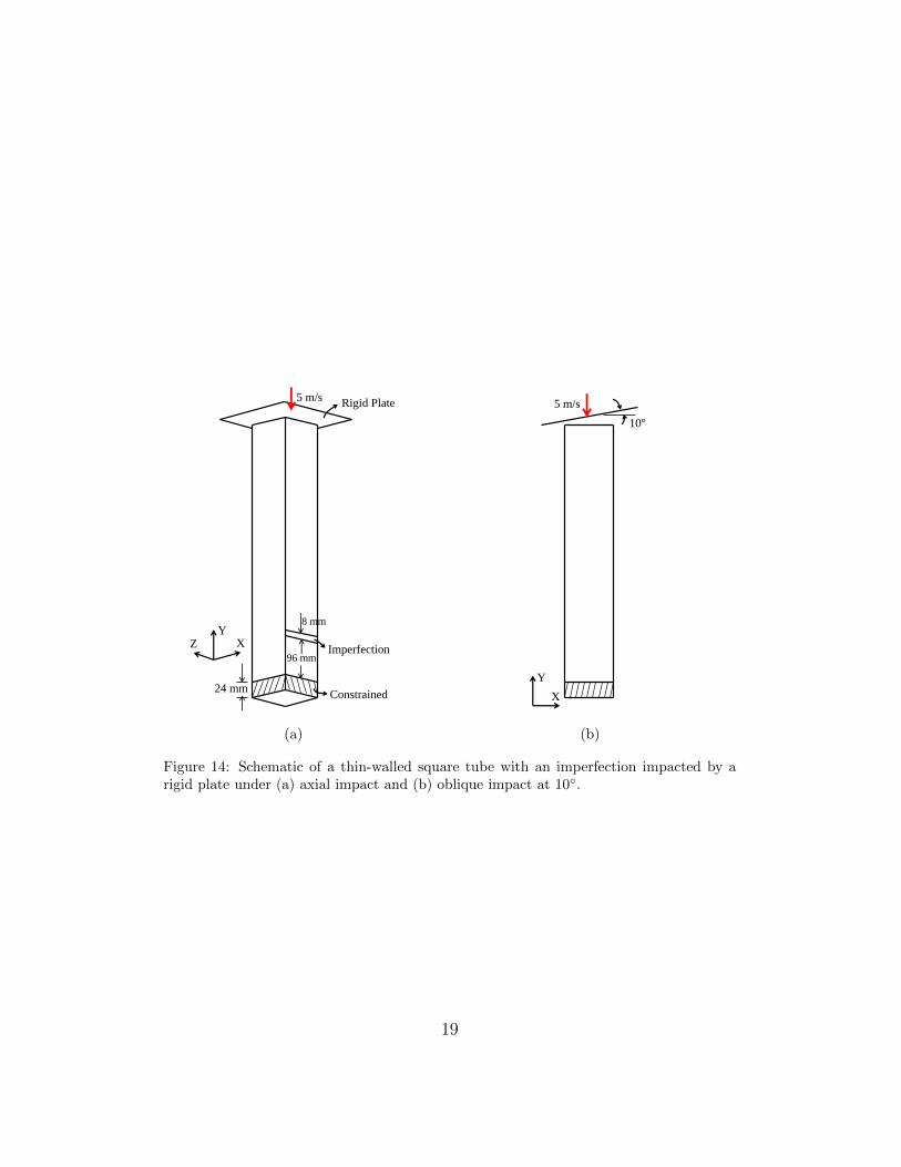
This example considers a relatively longer tube with two sets of outputport definitions to examine the utility of the proposed method for designingtubes undergoing oblique impacts. As a baseline, a thin-walled square tube480 mm long, 80 mm wide and with uniform thickness of 1.5 mm is impactedby a rigid plate. The tube is constrained at one end, and an imperfection isadded in the form of an 8 mm long and 1 mm thick patch close to the lowerend of the tube on one of its faces. The schematic of the tube and locationof the imperfection are shown in Fig. 14(a). The rigid plate, which has amass of 400 kg, is given an initial velocity of 5 m/s in the axial direction.Two different loading scenarios are considered: a) a pure axial impact; andb) an oblique impact with a loading angle of 10 as shown in Fig. 14(b). Thesimulation time for both cases is 0.03 seconds.
Like in the previous example, a mesh convergence study is performed
18
24 mm
96 mm
8 mm
5 m/s Rigid Plate
Imperfection
Constrained
X Y
Z
Y
X
5 m/s
10°
(a) (b)
Figure 14: Schematic of a thin-walled square tube with an imperfection impacted by arigid plate under (a) axial impact and (b) oblique impact at 10.
19

with various mesh refinements for both the pure axial and oblique impacts.The results, corresponding to the four representative mesh sizes, are shownin Figs. 15 and 16. The force-time behavior of the model with the 80×60mesh resolution for both axial and oblique impacts is significantly differentthan that of the other three models with finer mesh resolutions. During pureaxial crushing, the first fold appears at the imperfection for all four models.The second fold forms above the first fold in the model with the 80×60 meshresolution, whereas the second fold forms below the first fold in the otherthree finer mesh models. The peak force corresponding to the third fold inthe model with the 80×60 mesh resolution is comparatively smaller than thecorresponding force for the other three models. This results in less overallenergy absorption in the 80×60 model during pure axial crushing, which canbe seen in Fig. 16(a).
During the oblique impact, global bending in the 80×60 model starts alittle later than in the other three models. This slight delay in the globalbending results in comparatively lower energy absorption for the model withthe 80×60 mesh resolution. The energy absorption values for the models with160×240 and 240×240 mesh resolution are very close in the cases of bothpure axial and oblique impacts. Hence, based on the force-time behavior, theamount of energy absorption, and the deformation pattern, a mesh resolutionof 160×240 (element size of 2 mm × 2 mm) is found to be sufficient and usedfor the subsequent studies. Note that 160 is the number of elements alongthe square perimeter (40 elements on each face).
Figure 17 shows the deformation behavior of the uniformly thick tubewith an imperfection under pure axial crushing by the rigid plate with aninitial velocity of 5 m/s (Fig. 14(a)). The buckling starts at the imperfectionand progresses in both directions afterwards. When the angle of impact isincreased to 10 during the oblique loading, the tube undergoes Euler-typebuckling (global bending) after a few folds form at the top as shown in Fig. 18.As found in similar studies [22, 23], the onset of global bending adverselyaffects the load carrying capacity and hence, the energy absorption. This canbe confirmed by Fig. 19 in which the force-time and energy-time histories forthe pure axial impact are compared with those for the oblique impact. Theforce drops to 0 and energy saturates once the tube loses contact with therigid plate after the onset of global bending during the oblique impact.
In order to ensure that progressive buckling starts from the loading endduring pure axial crushing and to avoid or delay the onset of global bendingduring the oblique impact, two sets of output ports close to the loading
20

0 0.005 0.01 0.015 0.02 0.025 0.030
2
4
6
8
10
12
14x 104
Time (sec)
Forc
e (N
)
80×60160×120160×240240×240
0 0.005 0.01 0.015 0.02 0.025 0.030
1
2
3
4
5x 10⁴
Time (sec)
Forc
e (N
)
80×60160×120160×240240×240
(a) (b)
Figure 15: Mesh convergence study: Force-time behavior of the square tube modeled withfour different mesh resolutions under (a) axial impact and (b) oblique impact at 10.
80x60 160x120 160x240 240x2403.74
3.76
3.78
3.8
3.82
3.84
3.86
3.88
3.9
3.92x 10⁶
Mesh Resolution
Tota
l Ene
rgy
Abs
orpt
ion
(N-m
m)
80x60 160x120 160x240 240x2401.55
1.6
1.65
1.7
1.75
1.8
1.85
1.9
1.95x 10⁶
Mesh Resolution
Tota
l Ene
rgy
Abs
orpt
ion
(N-m
m)
(a) (b)
Figure 16: Mesh convergence study: Variation in the total energy absorption of a uniformlythick tube modeled with four different mesh resolutions for (a) axial impact and (b) obliqueimpact at 10.
21
(a) (b) (c)
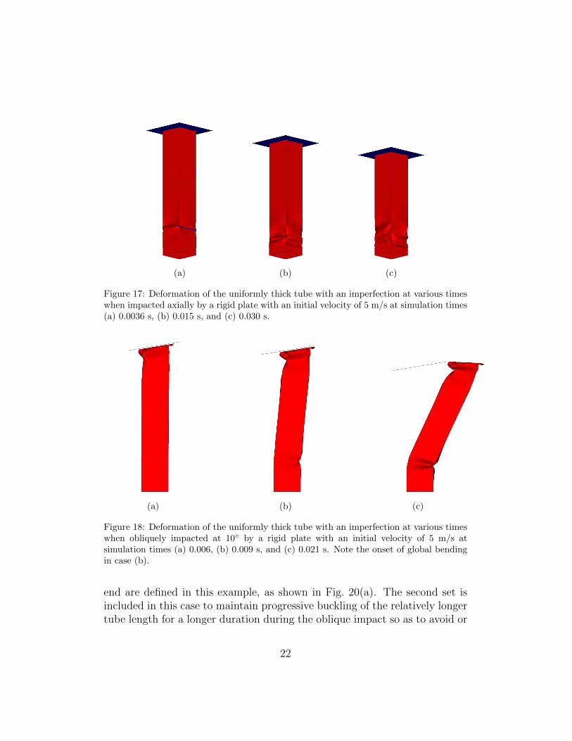
Figure 17: Deformation of the uniformly thick tube with an imperfection at various timeswhen impacted axially by a rigid plate with an initial velocity of 5 m/s at simulation times(a) 0.0036 s, (b) 0.015 s, and (c) 0.030 s.
(a) (b) (c)
Figure 18: Deformation of the uniformly thick tube with an imperfection at various timeswhen obliquely impacted at 10 by a rigid plate with an initial velocity of 5 m/s atsimulation times (a) 0.006, (b) 0.009 s, and (c) 0.021 s. Note the onset of global bendingin case (b).
end are defined in this example, as shown in Fig. 20(a). The second set isincluded in this case to maintain progressive buckling of the relatively longertube length for a longer duration during the oblique impact so as to avoid or
22

0 0.005 0.01 0.015 0.02 0.025 0.030
2
4
6
8
10
12x 104
Time (sec)
Forc
e (N
)
0 Degree10 Degree
0 0.005 0.01 0.015 0.02 0.025 0.030
0.5
1
1.5
2
2.5
3
3.5
4x 10⁶
Time (sec)
Ener
gy (N
-mm
)
0 Degree10 Degree
(a) (b)
Figure 19: Comparison of the dynamic response for the uniformly thick tube under axialand oblique impacts: (a) force vs. time and (b) energy vs. time.
delay the transition to global bending. The first set of output ports (pointinginward) are defined close to the loading end at a distance of 40 mm from thefree end of the tube. The second set of output ports are defined 80 mm belowthe first set, assuming 40 mm to be half the wavelength of deformation inthis case. A good starting point for deciding the relative distance betweenthe output ports is to use the wavelength of deformation from the simulationof the original uniformly thick tube. However, a more rigorous techniquewould use the relative distance between the output ports as an additionaldesign variable in a two-stage design method.
During the topometry design, the thickness variable in this case is allowedto vary between an upper bound (tmax) of 1.8 mm and a lower bound (tmin)of 1.2 mm. The average thickness target (T ∗) is set to 1.5 mm so that thefinal mass of the designed tube remains the same as the mass of the originaluniformly thick tube. As in the previous example, the imposed imperfectionis not considered during the design process. Figure 20(b) shows the thicknessdistribution of the designed tube. As in the previous example, face A has an“hourglass” shape with a higher thickness (1.8 mm) in the first 80 mm of thetube length. This thickness distribution on face A, along with the thicknessdistribution on face B in the first 80 mm of the tube length, initiates a fold ata 40 mm distance from the free end corresponding to the location of the firstset of output ports (O/P-1). In addition, a second smaller hourglass-shaped
23

O/P-1
O/P-2
A B
40 mm
80 mm
(a) (b)
Figure 20: Optimal design of a thin-walled structure with a single set of output ports: (a)output port definition and (b) thickness distribution for the designed tube.
thickness distribution on face A corresponds to the second set of output ports(O/P-2).
Figure 21 shows the deformation behavior of the designed tube underpure axial crushing. Note that the imperfection considered for the originaluniformly thick tube is added back to the designed tube in order to makereasonable comparisons. As predicted, the buckling starts at the first set ofoutput ports (Fig. 21(a)) in the prescribed symmetric mode, and it continuesdownwards. Moreover, the tube also buckles at the location corresponding tothe second set of output ports (Fig. 21(c)) in a desired fashion. This showsthat the proposed method can design tubes with multiple predefined bucklezones.
Next, the designed tube is tested under oblique impact (10), and the de-formation behavior at various times is shown in Fig. 22. Unlike the uniformlythick tube, the designed tube continues to buckle progressively, completelyavoiding the transition to global bending. This behavior of the designedtube represents an increase in the load-carrying capacity compared to theuniformly thick tube, which can be seen in Fig. 23(a). Also, the increasein the load-carrying capacity means more energy absorption as shown in
24

(a) (b) (c) (d)
Figure 21: Deformation of the designed tube with an imperfection at various times whenimpacted axially by a rigid plate with an initial velocity of 5 m/s for simulation times (a)0.006 s, (b) 0.015 s, (c) 0.0222 s, (d) 0.030 s
Fig. 23(b). The designed tube absorbs ∼ 80% more energy than the uni-formly thick tube during the simulation time of 0.03 seconds. Notably, theimpact between the tube’s lobes has a higher magnitude than the initial im-pact between the rigid wall and the free end of the tube. This situation isactually not uncommon during oblique impacts since the initial deformationof the tube’s edge results in a reaction force of less magnitude than the oneobserved when the impact area increases below a folding lobe.
The present example has shown that the proposed method can be used todesign long thin-walled square tubes with multiple predefined buckle zones.In addition, to enforce a progressive buckling starting from the loading end,these enforced buckle zones also can delay or avoid the onset of global bendingduring oblique impacts with load angles higher than the critical value. Inboth examples, a common trend in terms of design (hourglass shape) hasbeen found that effectively triggers the buckling in a symmetric mode atdesired locations along the length of the tube.
6. Discussion
The proposed design optimization method, based on compliant mech-anism design and displacement maximization of output ports, enables thecreation of enforced buckle zones that act as triggering mechanisms, even in
25

(a) t = 0.006 s (b) t = 0.012 s (c) t = 0.0222 s (d) t = 0.030 s
Figure 22: Deformation of the designed tube with an imperfection at various times whenimpacted obliquely (10) by a rigid plate with an initial velocity of 5 m/s.
0 0.005 0.01 0.015 0.02 0.025 0.030
1
2
3
4
5x 10⁴
Time (sec)
Forc
e (N
)
Uniform TubeDesigned Tube
0 0.005 0.01 0.015 0.02 0.025 0.030
0.5
1
1.5
2
2.5
3x 10⁶
Time (sec)
Ener
gy (N
-mm
)
Uniform TubeDesigned Tube
(a) Force-time history (b) Energy-time history
Figure 23: Comparison of the (a) force-time and (b) energy-time histories of the designedtube and the uniformly thick tube during the oblique impact.
the presence of geometric imperfections. This approach offers the benefits of:(a) initiating a specific axial collapse mode (symmetric in the present case),(b) stabilizing the collapse process, and (c) reducing the peak force, which isdesirable for crashworthiness. The presence of enforced buckle zones in thetop portion of the designed tubes helps to avoid or delay the onset of global
26
bending during oblique impacts with load angles higher than the criticalvalue. Note that large imperfections and/or oblique loadings at a very highangle of impact may still result in undesirable behavior. Such cases shouldbe handled differently, for example by improving the manufacturing processto reduce the imperfections and making changes in the basic geometry of thedesign to handle oblique loads with high impact angles. In addition to tubeswith square cross sections, the present method can also be used for tubeswith other regular cross sections such as rectangular, circular, polygonal, oreven open sections like C and hat-shaped channels as long as the meshing isuniform.
The designed tubes with variable thickness distribution obtained with thepresent method are manufacturable with modern manufacturing techniquestypically used for tailor-welded blanks (TWBs). A TWB is a part composedof different strengths or thicknesses of steel, joined usually by a laser weld.TWBs are increasingly gaining popularity among the automakers to reducethe weight of various sheet metal components without compromising thestrength. Some common applications of TWBs in the automotive industryare the door inners, upper front rails, and B-pillars. Notably, if TWB isconsidered to fabricate the designed tubes, the effect of the welding must beincluded in the computational models.
The designs obtained with the present method can be simplified for easeof manufacture by grouping the elements based on their thicknesses. Theelements with thickness near or equal to the upper bound (tmax) are collectedin one group and assigned a thickness of tmax. Similarly, elements with athickness close to the lower bound are collected in another group and assigneda thickness equal to tmin. All of the remaining elements whose thickness isgenerally close to the mean thickness (T ∗) are placed in the last group, and acommon thickness equal to T ∗ is assigned to them. Figure 24 shows the resultof using such a simplification by grouping the elements for the final designobtained in the first example. Since most of the elements in the final designhave a thickness close to the upper bound, lower bound or mean value, thesimplified design is very similar to the final design in terms of both thicknessdistribution and performance. These simplified designs with 3-4 discretelevels of thickness can be manufactured using patch tailor welded blanks.A patch TWB overlays one blank of material on top of another blank toadd thickness (strength) where it is needed [36]. The two blanks are joined,usually by spot welds, before forming.
One of the limitations of the present method is the absence of a well-
27

(a) Final design (b) Final design (after simplification)
Figure 24: (a) Final design from the first example and (b) simplified design after groupingthe elements based on their thicknesses.
defined rule to decide the location of the first set of output ports and thedistance between successive sets of output ports. Although it is reasonableto place these output ports based on the wavelength of deformation (distancebetween two successive folds) during the axial crushing of a uniformly thicktube, a more rigorous approach can be developed by incorporating the per-formance measures like peak force and energy absorption in deciding the portlocations. For future work, the number of output ports and their locationsalong the length of the tube can be parameterized, and a two-stage designmethod can be formulated with the objectives of minimizing the peak forceand maximizing the energy absorption.
7. Summary
This work introduces a new method for designing thin-walled tubes un-der axial and oblique impacts. The method consists of solving a compliantmechanism design problem within the thin wall of the structure. This designproblem, posed as mutual potential energy maximization, relies on the defi-nition of output ports. The location of the output ports, or enforced bucklezones, are in agreement with the wavelength of deformation during the axialcrushing of a uniformly thick tube. In this work, the optimization problem
28
is solved using the HCA algorithm.The optimization problem formulation includes mutual potential energy
and mass functions. The results demonstrate improved crashworthiness interms of a desirable progressive buckling and lower peak crushing force with-out increasing the structure’s mass, with a less desirable reduction in totalenergy absorption. The results are demonstrated in thin-walled structureswith width-to-thickness ratios w/t > 40.8, but there are no restriction to ap-ply this approach to other configurations. Using the present method, squaretubes can be designed to exhibit buckling starting from the loading (impact)end and systematically progressing toward the rear end, even in the pres-ence of reasonable geometric imperfections and asymmetries in the loadingconditions.
8. Acknowledgments
This material is based upon work supported by the Honda R&D Amer-icas. Any opinions, findings and conclusions or recommendations expressedin this material are those of the author(s) and do not necessarily reflect theviews of Honda R&D Americas.
[1] A. Pugsley, The Quarterly Journal of Mechanics and Applied Mathe-matics 13 (1960) 1–9.
[2] J. M. Alexander, The Quarterly Journal of Mechanics and AppliedMathematics 13 (1960) 10–15.
[3] W. Abramowicz, N. Jones, International Journal of Impact Engineering2 (1984) 263–281.
[4] W. Abramowicz, International Journal of Impact Engineering 1 (1983)309–317.
[5] T. Wierzbicki, W. Abramowicz, Journal of Applied Mechanics 50 (1983)727–734.
[6] M. Langseth, O. S. Hopperstad, A. G. Hanssen, Thin-Walled Structures32 (1998) 127–150.
[7] V. Tarigopula, M. Langseth, O. Hopperstad, A. Clausen, InternationalJournal of Impact Engineering 32 (2006) 847–882.
29

[8] P. Fyllingen, O. Hopperstad, A. Hanssen, M. Langseth, Thin-WalledStructures 48 (2010) 134–142.
[9] Z. Kazanci, K.-J. Bathe, International Journal of Impact Engineering42 (2012) 80 – 88.
[10] N. Jones, Structural Impact, Cambridge University Press, 1997.
[11] P. H. Thornton, C. L. Magee, Journal of Engineering Materials andTechnology 99 (1977) 114–120.
[12] X. Zhang, G. Cheng, Z. You, H. Zhang, Thin-Walled Structures 45(2007) 737–746.
[13] N. Chase, R. C. Averill, R. Sidhu, SAE world congress & exhibition(2009).
[14] H. El-Hage, P. K. Mallick, N. Zamani, International Journal of Crash-worthiness 10 (2005) 183–196.
[15] S. Lee, C. Hahn, M. Rhee, J.-E. Oh, Materials & Design 20 (1999) 31–40.
[16] Y. Liu, Thin-Walled Structures 46 (2008) 1329–1337.
[17] A. Najafi, M. Rais-Rohani, Thin-Walled Structures 49 (2011) 1–12.
[18] X. Zhang, G. Cheng, International Journal of Impact Engineering 34(2007) 1739–1752.
[19] F. Samer, F. Tarlochan, H. Samaka, International Journal of Researchin Engineering and Technology 2 (2013) 109–116.
[20] S. Salehghaffari, M. Rais-Rohani, A. Najafi, Thin-Walled Structures 49(2011) 397–408.
[21] S. C. K. Yuen, G. N. Nurick, Applied Mechanics Reviews 61 (2008)020802.
[22] D. C. Han, S. H. Park, Thin-Walled Structures 35 (1999) 167–184.
[23] A. Reyes, M. Langseth, O. S. Hopperstad, International Journal of Me-chanical Sciences 44 (2002) 1965–1984.
30

[24] C. Mozumder, J. E. Renaud, A. Tovar, Thin-Walled Structures 60 (2012)100–120.
[25] P. Bandi, A. Tovar, J. E. Renaud, in: Proceedings of the 52nd AIAAStructures, Strucutural Dynamics, and Materials Conference, Denver,CO.
[26] O. Sigmund, Mech. Struct. & Machines 25 (1997) 495–526.
[27] M. P. Bendsøe, O. Sigmund, Topology Optimization: Theory, Methodsand Applications, Springer-Verlag, Berlin, 2003.
[28] M. I. Frecker, G. K. Ananthasuresh, S. Nishiwaki, N. Kikuchi, S. Kota,Journal of Mechanical Design 119 (1997) 238–245.
[29] A. Saxena, , G. K. Ananthasuresh, Struct. Multidisc. Optim. 19 (2000)36–49.
[30] A. Tovar, N. M. Patel, G. L. Niebur, M. Sen, J. E. Renaud, Journal ofMechanical Design 128 (2006) 1205–1216.
[31] A. Tovar, K. Khandelwal, Engineering Structures 48 (2013) 674 – 682.
[32] P. Bandi, J. P. Schmiedeler, A. Tovar, Journal of Mechanical Design 135(2013) 091002.
[33] N. Peixinho, N. Jones, A. Pinho, Journal de Physique IV 110 (2003)717–722.
[34] J. Hallquist, LS-DYNA theoretical manual, Livermore software technol-ogy corporation (LSTC), 2006.
[35] R. L. Weber, K. V. Manning, M. W. White, College Physics, McGraw-Hill, 4th edition, 1965.
[36] Tailor welded blank applications and manufacturing - A state-of-the-artsurvey, Technical Report, The Auto/Steel Partnership, 2001.
31