design of pressure vessel for the hydrocarbon release from ... · design of pressure vessel for the...
TRANSCRIPT
International Research Journal of Engineering and Technology (IRJET) e-ISSN: 2395-0056
Volume: 05 Issue: 07 | July 2018 www.irjet.net p-ISSN: 2395-0072
© 2018, IRJET | Impact Factor value: 7.211 | ISO 9001:2008 Certified Journal | Page 2230
Design of Pressure vessel for the Hydrocarbon release from the Vent
Header Lines
Akhilesh Bhagwat , Deepkumar Chaudhari , Siddharth Kamat ,Bhargav Mangesh Joshi
Student, Department of mechanical engineering, Modern college of engineering, Pune-5
---------------------------------------------------------------------***---------------------------------------------------------------------Abstract – Flaring is the controlled burning of natural gas in the course of routine oil and gas production operations. This burning occurs at the end of flare stock or boom. Therefore, the paper deals with the design of pressure vessel for the collection of hydrocarbon release from the vent header lines of pilot plant. The components of a horizontal vessel like shell, head, and supports have been designed as per the ASME code section VIII Div. 1. It deals with suitable material selection and manual design of the vessel components along with validation from ANSYS. In order to avoid the release of hazardous chemicals or liquids, a pressure vessel is designed using section VIII, Div. 1(Ed 2015). Hydrostatic and radiographic tests have been performed on the vessel to determine the ability of the vessel to withstand various pressures. Key Words: ASME codes & standards, shell, head, saddle, Tests, APV
1.INTRODUCTION
Vessels and tanks that carry, store, or receive fluids under pressure are called pressure vessels. The inside pressure is usually higher than the outside pressure except for some isolated conditions. Pressure vessels often combine high pressures together with high temperatures and in some cases flammable fluids. Pressure vessel V300 has been designed for a pilot plant. It is to be designed for collecting hydrocarbon liquids emerging from vent header lines. Hence the material selected must be given either corrosion allowance or the material must be resistant to corrosion caused by hydrocarbons, whichever is safe and feasible. Hence, the economical design of a pressure vessel and its components has been made in the subsequent sections.
1.1 Literature Review The book consists of design procedure for the different components of the pressure vessel including the information about the materials to be used for construction as per the application. [1]
This section of the ASME code deals with the rules for the construction of the pressure vessel from the material procurement to the manufacturing and testing [2] This section deals with the material specifications for the construction of pressure vessel and the part D consists of the properties of the materials. [3] Stiffening rings are the popular way of controlling stress in certain locations and they prove to be cost effective. The paper deals with quantifying the role of stiffening rings. [4]
1.2 Introduction to ASME code
The organization of the ASME pressure vessel code is as follows:
Section II: Material Specification: • Ferrous Material Specifications – Part A • Non-ferrous Material Specifications – Part B • Specifications for Welding Rods, Electrodes, and
Filler Metals –Part C • Properties – Part D Section VIII: • Division 1: Pressure Vessels – Rules for
construction. • Division 2: Pressure Vessels – Alternative Rules.
1.3 Guidelines from ASME
UG-1 Scope UG-4 General Materials UG-27 (C) Cylindrical Shells UG-32 F Ellipsoidal Heads UG 40 Limits Of Reinforcement UG-45 Nozzle Neck Thickness
1.4 Nomenclature APV : American Pressure Vessel ASME : American Society of Mechanical Engineers UG : Unfired Vessels General guidelines V300 : Liquid collection tank for collecting hydrocarbon release from vent header lines
International Research Journal of Engineering and Technology (IRJET) e-ISSN: 2395-0056
Volume: 05 Issue: 07 | July 2018 www.irjet.net p-ISSN: 2395-0072
© 2018, IRJET | Impact Factor value: 7.211 | ISO 9001:2008 Certified Journal | Page 2231
2. PROBLEM DEFINITION To design and manufacture the pressure vessel for hydrocarbon toxic release from the vent header lines for the design pressure and temperature of 10 kg/cm2 and 70⁰C respectively with selection of a suitable material which will give safety and is most economical and to design the pressure vessel to avoid environmental contamination from a pilot plant including the safety features. It also aims at designing shell, head, supports, openings and reinforcements.
3. MATERIAL SELECTION FOR V300 Several of materials have been use in pressure vessel fabrication. The selection of material is based on the design requirement. All the materials used in the manufacture of the receivers shall comply with the requirements of the relevant design code. The material SA240GR316 for manufacturing of V300 has been selected. Grade 316 is immune from sensitization (grain boundary carbide precipitation). SA240 GR316 is a molybdenum-bearing austenitic stainless steel which is more resistant to general corrosion and pitting/ crevice corrosion than the conventional chromium-nickel austenitic stainless steels such as Type 304. A case study of the chemical composition would reveal that Type 316 is considerably more resistant than any of the other chromium-nickel types to solutions of Sulphuric acid. At temperatures as high as 120°F (49°C), Types 316 and 317 are resistant to concentrations of this acid up to 5 percent. At temperatures under 100°F (38°C), this alloy has excellent resistance to higher concentrations. Where condensation of sulphur-bearing gases occurs, this alloy is much more resistant than other types of stainless steels. In such applications, however, the acid concentration has a marked influence on the rate of attack and should be carefully determined. The molybdenum-bearing Type 316 stainless steel also provides resistance to a wide variety of other environments. The material properties have been studied from Section II of the code, Part D. [3]
4. INPUT PARAMETERS
Max. operating temperature = 50⁰C Max. Operating pressure = 3.5Kg/cm2 Design temperature = 70⁰C Design pressure = 10Kg Relief set pressure = Atm. Material = SA240GR316 Orientation = Horizontal Shell diameter = 0.75m Length of shell = 2.5m Nominal volume = 1.5m3
4.1 Nozzles and Connections Liquid Inlet = 2 inches Make-Up = 3 inches Spare = 2 inches Liquid Inlet = 2 inches Vent = 2 inches Liquid Inlet = 2 inches Liquid Indicator (high) = 1 inch Liquid Indicator (low) = 1 inch Spare = 1 inch The Design pressure is taken as equal to maximum operating pressure including static head + 10%. Normal design pressure = 1.1Pmax
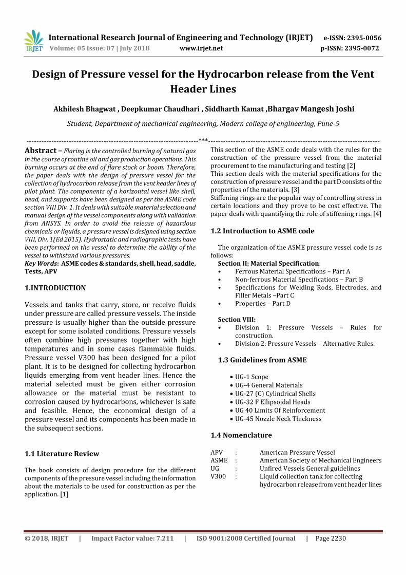
5. DESIGN OF SHELL The Shell is the cylindrical component or the main body of the vessel which encloses the contents of the vessel. It is designed as per the ASME code section VIII, UG-27 for the shells subjected to internal pressure and UG-28 for the shells subjected to external pressure.[2]
Fig. 1 APV calculations for design of Shell
International Research Journal of Engineering and Technology (IRJET) e-ISSN: 2395-0056
Volume: 05 Issue: 07 | July 2018 www.irjet.net p-ISSN: 2395-0072
© 2018, IRJET | Impact Factor value: 7.211 | ISO 9001:2008 Certified Journal | Page 2232
Fig. 2 Model of Shell on Solidworks
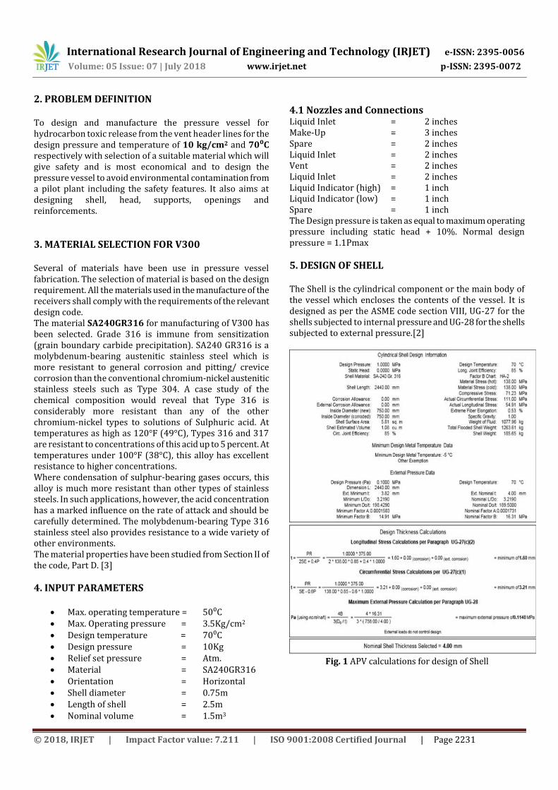
6. DESIGN OF ELLIPSOIDAL HEAD The head is the part of the vessel that encloses the vessel shells from both sides. Ellipsoidal Heads(2:1) : pressures over 1.5 N/mm2 An acceptable approximation of a 2:1 ellipsoidal head is one with a knuckle radius of 0.17D and a spherical radius of 0.90D[2]
Fig. 3 APV calculations for design of Head
Fig. 4 Model of Ellipsoidal head on Solidworks
6. 1 Stiffening Rings under External Pressure External stiffening rings will be attached to the shell by welding or brazing if required The available moment of inertia of a circumferential stiffening ring shall not be less than that determined by one of the following two formulas as mentioned in the UG-30. Compare the required moment of inertia with the actual moment of inertia of selected member. If actual exceeds that which is required then design is acceptable. Here, for V300, the value of external pressure is under acceptable limits. Hence, no stiffener is added in the
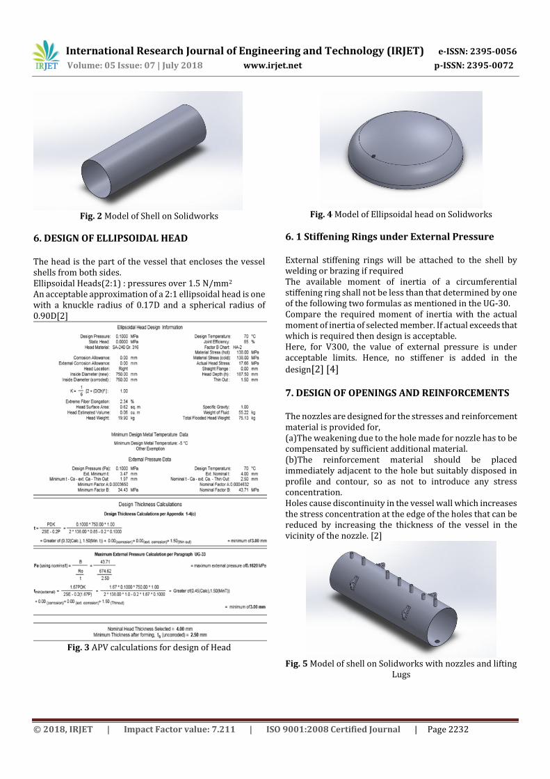
design[2] [4] 7. DESIGN OF OPENINGS AND REINFORCEMENTS The nozzles are designed for the stresses and reinforcement material is provided for, (a)The weakening due to the hole made for nozzle has to be compensated by sufficient additional material. (b)The reinforcement material should be placed immediately adjacent to the hole but suitably disposed in profile and contour, so as not to introduce any stress concentration. Holes cause discontinuity in the vessel wall which increases the stress concentration at the edge of the holes that can be reduced by increasing the thickness of the vessel in the vicinity of the nozzle. [2]
Fig. 5 Model of shell on Solidworks with nozzles and lifting
Lugs

International Research Journal of Engineering and Technology (IRJET) e-ISSN: 2395-0056
Volume: 05 Issue: 07 | July 2018 www.irjet.net p-ISSN: 2395-0072
© 2018, IRJET | Impact Factor value: 7.211 | ISO 9001:2008 Certified Journal | Page 2233
Fig. 6 APV Sheet for Nozzle (A1-Liquid Inlet) Calculations
Fig. 7 APV Sheet for Nozzle (A1-Liquid Inlet) Calculations
8. SUPPORTS FOR VESSEL Horizontally kept cylindrical pressure vessels are generally supported on twin saddle supports.
Fig. 8 Model of Saddle supports on Solidworks
Fig. 9 Flange Dimensions
Fig. 10 Summary information

International Research Journal of Engineering and Technology (IRJET) e-ISSN: 2395-0056
Volume: 05 Issue: 07 | July 2018 www.irjet.net p-ISSN: 2395-0072
© 2018, IRJET | Impact Factor value: 7.211 | ISO 9001:2008 Certified Journal | Page 2234
9. FINAL ASSEMBLY OF V300
Fig. 11 Auto-cad drawing of V300
Fig. 12 Assembly of V300 on Solidworks
10. ANALYSIS ON ANSYS WORKBENCH
Fig. 13 Stress Analysis
Fig. 14 Deflection Analysis
11. HYDROSTATIC TEST REPORT Min. Test temperature= MDMT + 30°F Max. Test temperature = 120°F MDMT is the pressure vessel minimum design metal temperature which is 5⁰C
Fig. 15 Hydrostatic Test Report

International Research Journal of Engineering and Technology (IRJET) e-ISSN: 2395-0056
Volume: 05 Issue: 07 | July 2018 www.irjet.net p-ISSN: 2395-0072
© 2018, IRJET | Impact Factor value: 7.211 | ISO 9001:2008 Certified Journal | Page 2235
12. RESULTS AND DISCUSSION The calculated values of thickness of every component are compared with the values obtained using APV software. Following table shows the comparative study of calculated values of thickness and values obtained from software. Table 1 Results Sr. No
Parameter Value Obtained from software (mm)
1. Shell thickness 4 2. Head thickness 4 3. Nozzle(1”) thickness 3.42 4. Nozzle(2”) thickness 3.91 5. Nozzle(3”) thickness 5.49
1. Design consistent with American Pressure Vessel (APV) software design.
2. Static structural analysis done in ANSYS Workbench 16.0. Design is safe.
3. Hydrostatic pressure test carried out on V300 at a pressure of 13 bar. No leakages or failure of components.
13. CONCLUSIONS Various materials available for pressure vessel are studied and suitable material for each component is selected. Thickness of shell, head and nozzle were calculated manually and validated using APV software. Cad design is extremely important since it will be provided to manufacturer and will be used for three dimensional drawings. If there is a minor mistake in the drawing then it may lead to the manufacturing defects, difficulties in assembly and failure of the vessel. Hydrostatic test is performed to check the leakages and pressure bearing capacity of the vessel, thus assured the safety. Pressure vessel accidents are one of the most severe and explosive accidents, leading to the loss of working personnel around it. Hence, the perfect design with all the tests must be carried out.
ACKNOWLEDGEMENT we would like to express my gratitude to Management of Xytel India Pvt. Ltd for providing the sponsored project and the company guide, Mr. Ajitsingh Chandel for providing his esteemed guidance related to the design, analysis and manufacturing of pressure vessel. The project would not have been successful without his useful and solicitous mentorship.
REFERENCES [1] Joshi’s Process equipment design, M.V. Joshi,
V.V.Mahajani, S.B. Umarji, Trinity Press, New Delhi, 1979, (Reprint-2014), pp.91-149
[2] ASME code section VIII, Div. 1 (Ed. 2015)
[3] ASME code section II, Part D, Properties
[4] Quantifying the role of stiffening rings in pressure vessels using FEA by Pushpa Khot, Dr. S.G. Taji, International Journal of Science, Engineering and Technology Research (IJSETR), Volume 5, Issue 1, January 2016.