design of mems based polymer microphone for hearing aid ... · microphone for hearing aid...
TRANSCRIPT

Design of MEMS Based Polymer Microphone for Hearing AidApplication
Girish G.K.1, Ramanuja H.S.2,Deepak K3,*Veda Sandeep Nagaraja4,and S.L.Pinjare5
1,2,3,4,5 Nitte Meenakshi Institute of Technology, Yelahanka, Bangalore*Corresponding author: ECE Dept, Govindapura, Gollahalli, Yelahanka, Bangalore
Abstract: This paper presents a condensermicrophone for hearing aid application. It gives abrief overview of different types of hearing aidsavailable in the market. The work looks into theprinciple of operation a of MEMS CondenserMicrophone (MCM) for hearing aid application.The stress versus pressure and Displacementversus arch length analysis has been carried out.The simulation work has been carried out inCOMSOL Multiphysics using Structuralmechanics and in specific Electromechanics.
Keywords: Microphone, MCM- MEMSCondenser Microphone, Readout Circuitry,CMOS.
1. Introduction
The microphones that are commerciallyavailable in market can be classified intodifferent categories depending on their principleof operation. A condenser microphone [1] is theone that calculates the change in acousticpressure by change in capacitance; apiezoelectric microphone is one that has theability to produce voltage when subjected topressure. A piezoresistive microphone is one thatchanges the resistance with change in appliedvoltage or pressure.
This paper presents a MCM which usesPolyimide as the material for the diaphragm andbackplate and the dielectric is air. The paper isdivided into mainly into 7 sections. The secondsection looks into different types of hearing aidsin the market. This is followed by the thirdsection which looks into the details of principleof operation as well as the structure of MCM.The fourth section gives a brief overview of theusage of COMSOL Multiphysics and the fifthsection gives the details of the differentmeasurements and analysis carried out in thework. The sixth section gives the simulationresults which is followed by the seventh sectionwhich analyzes the results obtained.
2. Hearing Aid
The hearing aids [2] available in the markethave the problem of directionality, sensitivityand audio range. During a field survey ofconsumers of different age groups using hearingaid for different periods, it was found that theyhave difficulty in hearing when driving, talkingover the phone and difficulty distinguishingbackground noise. There are many types ofhearing aids like Behind The Ear (BTE), In TheEar (ITE), In the Canal (ITC) and Completely Inthe Canal (CIC). A new type of hearing aid thathas been able to overcome severe hearing loss isthe Cochlear Implant hearing aid. There are alsodifferent types of hearing losses. Conductivehearing loss refers to a decrease in sound causedby a problem in the outer or middle ear andusually is treated by medical or surgicalintervention. The other type of hearing aid issensorineural loss which refers to the problemlocated in the inner ear or along the pathwaybetween the inner ear and the brain. This type ofhearing loss is almost not treatable but CochlearImplant [3] hearing aids are able to overcomethis loss to some extent.
3. MEMS Condenser Microphone
The MEMS condenser microphone has gainedimportance in the last decade or so because of itsease to fabricate. It basically works on theprinciple of operation of change in capacitancewith the applied voltage or pressure [4]. Thebasic structure of the MEMS condensermicrophone used in this paper is shown in figure1.
Figure 1. Structure of the MCM
It is made up of four layers. The bottom plate isthe gold electrode and it is required to give theinput to the readout circuitry. The materialproperties of Gold are given in table 1.
Table 1: Physics properties of GoldDescription Values UnitsYoung’sModulus E
70E9 Pascal
Poisson’s ratio 0.44 UnitLess
RelativePermittivity
0 Unitless
On top of this electrode the diaphragm isfabricated. The diaphragm is made up ofPolyimide. The material Properties of thePolyimide plates are given in table 2.
Table 2: Physics properties of PolyimideDescription Values UnitsYoung’s ModulusE
3.14E9 Pascal
Poisson’s ratio 0.35 UnitLess
RelativePermittivity
3.5 Unitless
The dielectric air is on top of the diaphragm andits thickness is 2µm. The polyimide backplate ison top of the air dielectric medium. Thebackplate has a thickness of thickness of 17µm.The microphone designed in this paper has adiaphragm of 1mm X 1mm dimension. For easein simulation, a 1/4th model has been used. Thedevice dimensions used in the 1/4th model hasbeen listed in table 2.
Table 2: Dimension of the MCMStructure name Dimensions Units
Diaphragm length 500 µm
Diaphragm width 500 µm
Air layer length 500 µmAir layer width 500 µmAir layer thickness 2 µmBack plate length 500 µmBack plate width 500 µmBack platethickness
17 µm
The backplate has acoustic holes. The backplatemakes up the fixed plate of the variable capacitorof MCM and the diaphragm makes up thevariable plate. Due to air pressure the diaphragmdeflates and hence the distance between the twoplates changes and hence the capacitance varies.This change in capacitance is readout using thegold electrode.
4. Use of COMSOL Multiphysics
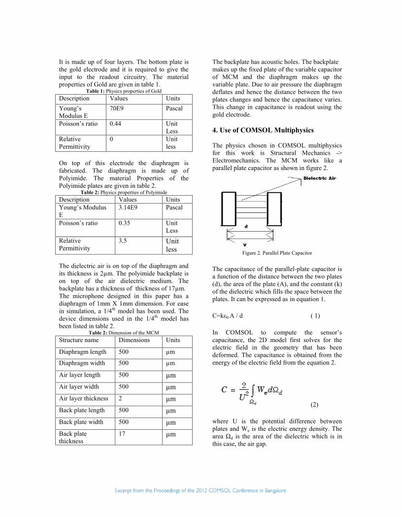
The physics chosen in COMSOL multiphysicsfor this work is Structural Mechanics ->Electromechanics. The MCM works like aparallel plate capacitor as shown in figure 2.
Figure 2. Parallel Plate Capacitor
The capacitance of the parallel-plate capacitor isa function of the distance between the two plates(d), the area of the plate (A), and the constant (k)of the dielectric which fills the space between theplates. It can be expressed as in equation 1.
C=kε0 A / d ( 1)
In COMSOL to compute the sensor’scapacitance, the 2D model first solves for theelectric field in the geometry that has beendeformed. The capacitance is obtained from theenergy of the electric field from the equation 2.
(2)
where U is the potential difference betweenplates and We is the electric energy density. Thearea Ωd is the area of the dielectric which is inthis case, the air gap.

In the 3D model, the capacitance is calculated byintegrating over the surface of the capacitoraccording to the equation 3.
(3)
here h denotes the local distance across thecapacitor and ε is the permittivity of air.
5. Measurements
In this work the pressure versus displacementanalysis has been carried out. The subsequentsection gives the graphical analysis of themeasurement. The displacement of thediaphragm with respect to the pressure appliedchanges the capacitance which in turn can be fedto a CMOS readout circuitry for furtherprocessing of the speech signal. The change incapacitance is very minimal and hence there is aneed for a preamplifier at the beginning of theCMOS readout circuitry to amplify the signalfrom the MCM and give it to the ADC and otherstages of the readout circuitry [5]. The stressversus pressure analysis has also been carried outin this work. For simulation purposes, we haveused only the bottom two layers of gold anddiaphragm for applying the pressure. Themeasurement has been carried out for fourdifferent thickness of the diaphragm.
6. Simulation results
The simulation work has been carried out forthe diaphragm thickness of 1μm, 2μm, 3μm and4μm. Figure 3 gives the stress versus pressureanalysis for a 1μm thick diaphragm.
Figure 3: Stress v/s pressure analysis for 1μm thickdiaphragm
The displacement versus arc length 3D plot isshown in figure 4 and the same 1D plot is shownin figure 5. Both of them are analyzed with thediaphragm thickness of 1μm.
Figure 4. Displacement versus arc length 3D plot for adiaphragm thickness of 1 1μm.
Figure 5. Displacement versus arc length 1D plot for adiaphragm thickness of 1 1μm.
7. Result Analysis
Table 4 gives the variation of the maximumdisplacement for the four different thickness ofthe diaphragm.
Table 4: Diaphragm thickness versus Maximumdisplacement
SlNo
Diaphragm thickness inμm
Maximumdisplacementin μm
1 1 μm 1.1842 2 μm 0.1883 3 μm 0.0654 4 μm 0.029
Figure 6 shows the above mentioned variation ofthe displacement as the thickness of thediaphragm is increased. As can be seen from theanalysis, the maximum displacement of the
diaphragm is decreased as the thickness isincreased.
Figure 6. Diaphragm thickness versus Maximumdisplacement
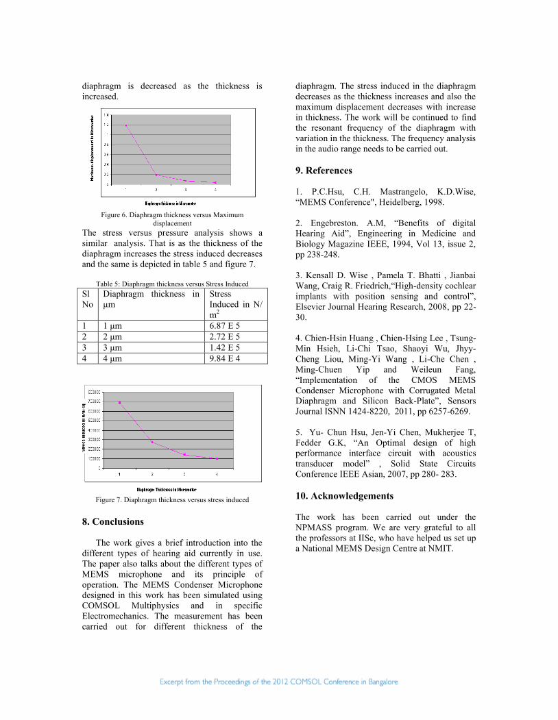
The stress versus pressure analysis shows asimilar analysis. That is as the thickness of thediaphragm increases the stress induced decreasesand the same is depicted in table 5 and figure 7.
Table 5: Diaphragm thickness versus Stress InducedSlNo
Diaphragm thickness inμm
StressInduced in N/m2
1 1 μm 6.87 E 52 2 μm 2.72 E 53 3 μm 1.42 E 54 4 μm 9.84 E 4
Figure 7. Diaphragm thickness versus stress induced
8. Conclusions
The work gives a brief introduction into thedifferent types of hearing aid currently in use.The paper also talks about the different types ofMEMS microphone and its principle ofoperation. The MEMS Condenser Microphonedesigned in this work has been simulated usingCOMSOL Multiphysics and in specificElectromechanics. The measurement has beencarried out for different thickness of the
diaphragm. The stress induced in the diaphragmdecreases as the thickness increases and also themaximum displacement decreases with increasein thickness. The work will be continued to findthe resonant frequency of the diaphragm withvariation in the thickness. The frequency analysisin the audio range needs to be carried out.
9. References
1. P.C.Hsu, C.H. Mastrangelo, K.D.Wise,“MEMS Conference", Heidelberg, 1998.
2. Engebreston. A.M, “Benefits of digitalHearing Aid”, Engineering in Medicine andBiology Magazine IEEE, 1994, Vol 13, issue 2,pp 238-248.
3. Kensall D. Wise , Pamela T. Bhatti , JianbaiWang, Craig R. Friedrich,“High-density cochlearimplants with position sensing and control”,Elsevier Journal Hearing Research, 2008, pp 22-30.
4. Chien-Hsin Huang , Chien-Hsing Lee , Tsung-Min Hsieh, Li-Chi Tsao, Shaoyi Wu, Jhyy-Cheng Liou, Ming-Yi Wang , Li-Che Chen ,Ming-Chuen Yip and Weileun Fang,“Implementation of the CMOS MEMSCondenser Microphone with Corrugated MetalDiaphragm and Silicon Back-Plate”, SensorsJournal ISNN 1424-8220, 2011, pp 6257-6269.
5. Yu- Chun Hsu, Jen-Yi Chen, Mukherjee T,Fedder G.K, “An Optimal design of highperformance interface circuit with acousticstransducer model” , Solid State CircuitsConference IEEE Asian, 2007, pp 280- 283.
10. Acknowledgements
The work has been carried out under theNPMASS program. We are very grateful to allthe professors at IISc, who have helped us set upa National MEMS Design Centre at NMIT.

Biography
Girish GK was born in Chitradurga,Karnataka on March 27, 1984. He graduated fromVTU in 2006. He received Masters from VisvesvarayaTechnological University in 2008 and is currentlyworking as Lecturer in E&CE Dept NMIT, Bangaloreand also pursuing Ph.D. under University of Mysore.
Ramanuja H S was born on April 28,1982. He received his Masters degree from BangaloreUniversity in 2006. He is a research scholar inElectronics Department, Nitte research and EducationAcademy, Bangalore.
Deepak K was born on Feb 16, 1985. Hereceived his Masters degree from Kuvempu Universityin 2007. He is a research scholar in ElectronicsDepartment, Nitte research and Education Academy,Bangalore.
Veda was born in Belgaum, Karnataka,India, on August 18, 1979. She graduated fromUniversity of Mysore in 2001. She received herMaster’s from Visvesvaraya Technological Universityin 2009 and is currently working as AssistantProfessor in E&CE Dept NMIT, Bangalore and alsopursuing Ph.D. under University of Mysore.
Pinjare was born in Betul Bazar in BetulDistrict MadhyaPradesh, India, on May 10, 1953. Hegraduated from the University of Mysore. He
completed his Ph.D from IIT Madras in 1981.Heworked at ITI Ltd as Deputy Chief Engineer.Currently he is a professor and PG Coordinator inE&CE Department NMIT Bangalore