design of magnetic components - samex ent · design of magnetic components ... in converter circuit...
TRANSCRIPT
Magnetics - 1�W.P. Robbins
Design of Magnetic Components
William P. Robbins�Dept. of Electrical and Computer Engineering�
University of Minnesota
A. Inductor/Transformer Design Relationships
B. Magnetic Cores and Materials
C. Power Dissipation in Copper Windings
D. Thermal Considerations
E. Analysis of Specific Inductor Design
F. Inductor Design Procedures
G. Analysis of Specific Transformer Design
H. Eddy Currents
J. Transformer Leakage Inductance
K. Transformer Design Procedures
Outline
Magnetics - 2�W.P. Robbins
Magnetic Component Design Responsibility of Circuit Designer
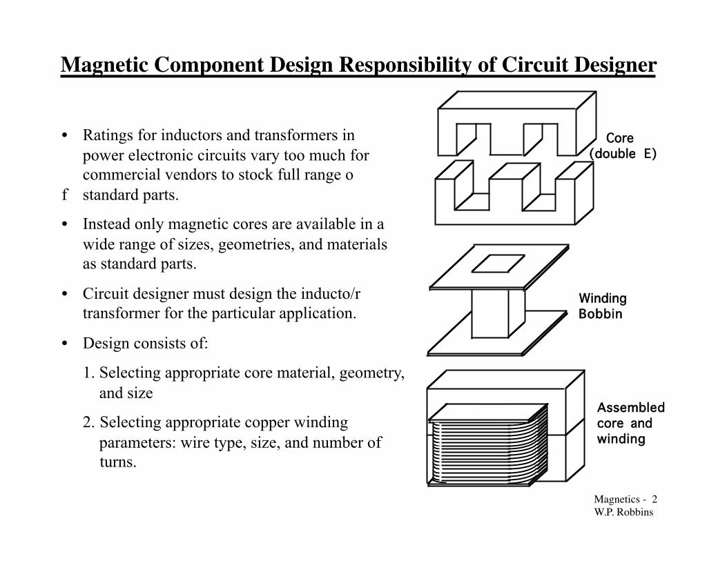
• Ratings for inductors and transformers in power electronic circuits vary too much for commercial vendors to stock full range of standard parts.
• Instead only magnetic cores are available in a wide range of sizes, geometries, and materials as standard parts.
• Circuit designer must design the inducto/r transformer for the particular application.
• Design consists of:
1. Selecting appropriate core material, geometry, and size
2. Selecting appropriate copper winding parameters: wire type, size, and number of
turns.
Core(double E)
Winding Bobbin
Assembled core and winding
Magnetics - 3�W.P. Robbins
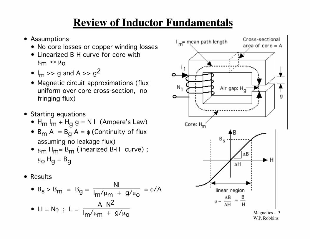
Review of Inductor Fundamentals • Assumptions
• No core losses or copper winding losses• Linearized B-H curve for core with
µm >> µo• lm >> g and A >> g2 • Magnetic circuit approximations (flux
uniform over core cross-section, nofringing flux)
• Starting equations• Hm lm + Hg g = N I (Ampere’s Law)• Bm A = Bg A = φ (Continuity of flux
assuming no leakage flux)• µm Hm= Bm (linearized B-H curve) ;
µo Hg = Bg
• Results
• Bs > Bm = Bg = NI
lm/µm + g/µo = φ/A
• LI = Nφ ; L = A N2
lm/µm + g/µo
Magnetics - 4�W.P. Robbins
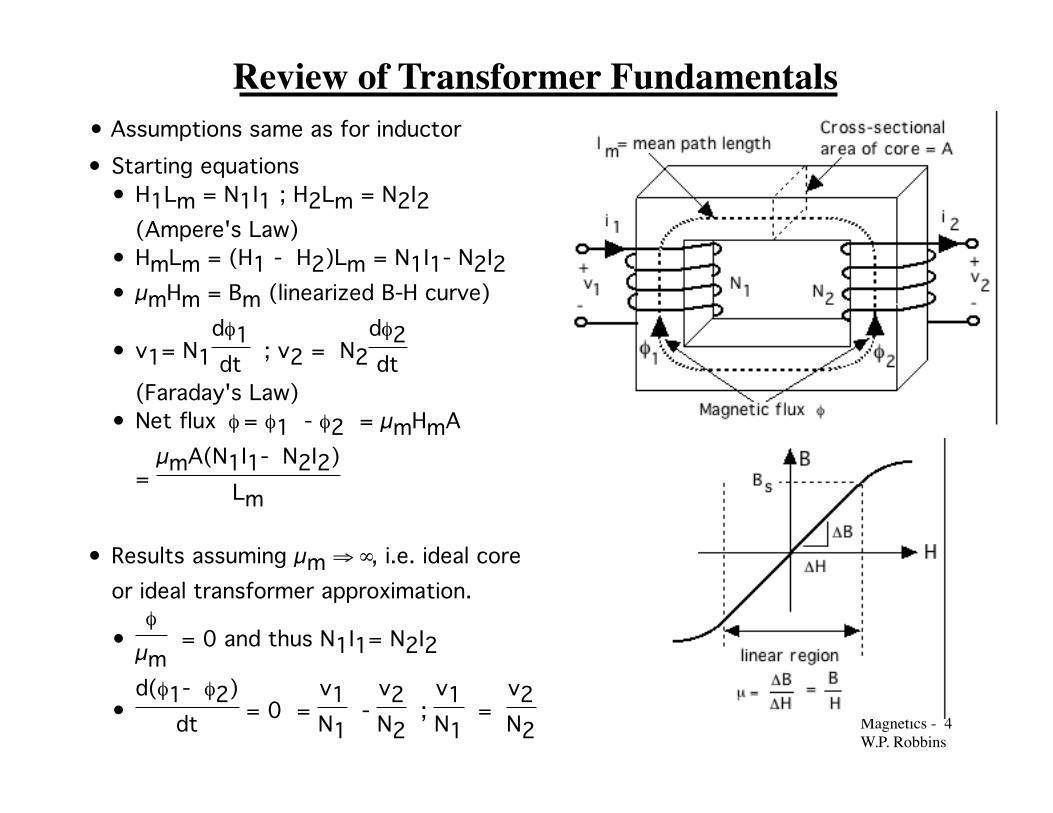
Review of Transformer Fundamentals • Assumptions same as for inductor • Starting equations
• H1Lm = N1I1 ; H2Lm = N2I2(Ampere's Law)
• HmLm = (H1 - H2)Lm = N1I1- N2I2• µmHm = Bm (linearized B-H curve)
• v1= N1dφ1dt ; v2 = N2
dφ2dt
(Faraday's Law)• Net flux φ = φ1 - φ2 = µmHmA
= µmA(N1I1- N2I2)
Lm
• Results assuming µm ⇒ ∞, i.e. ideal coreor ideal transformer approximation.
•φ
µm = 0 and thus N1I1= N2I2
•d(φ1- φ2)
dt = 0 = v1N1
- v2N2
; v1N1
= v2N2

Magnetics - 5�W.P. Robbins
Current/Flux Density Versus Core Size
fringing flux
g
core
• Larger electrical ratings require larger current I and larger flux density B.
• Core losses (hysteresis, eddy currents) increase as B2 (or greater)
• Winding (ohmic) losses increase as I2 and are accentuated at high frequencies (skin effect, proximity effect)
• To control component temperature, surface area of component and thus size of component must be increased to reject increased heat to ambient.
• At constant winding current density J and core flux density B, heat generation increases with volume V but surface area only increases as V2/3.
• Maximum J and B must be reduced as electrical ratings increase.
• Flux density B must be < Bs
• Higher electrical ratings ⇒ larger total flux ⇒ larger component size
• Flux leakage, nonuniform flux distribution complicate design
Magnetics - 6�W.P. Robbins
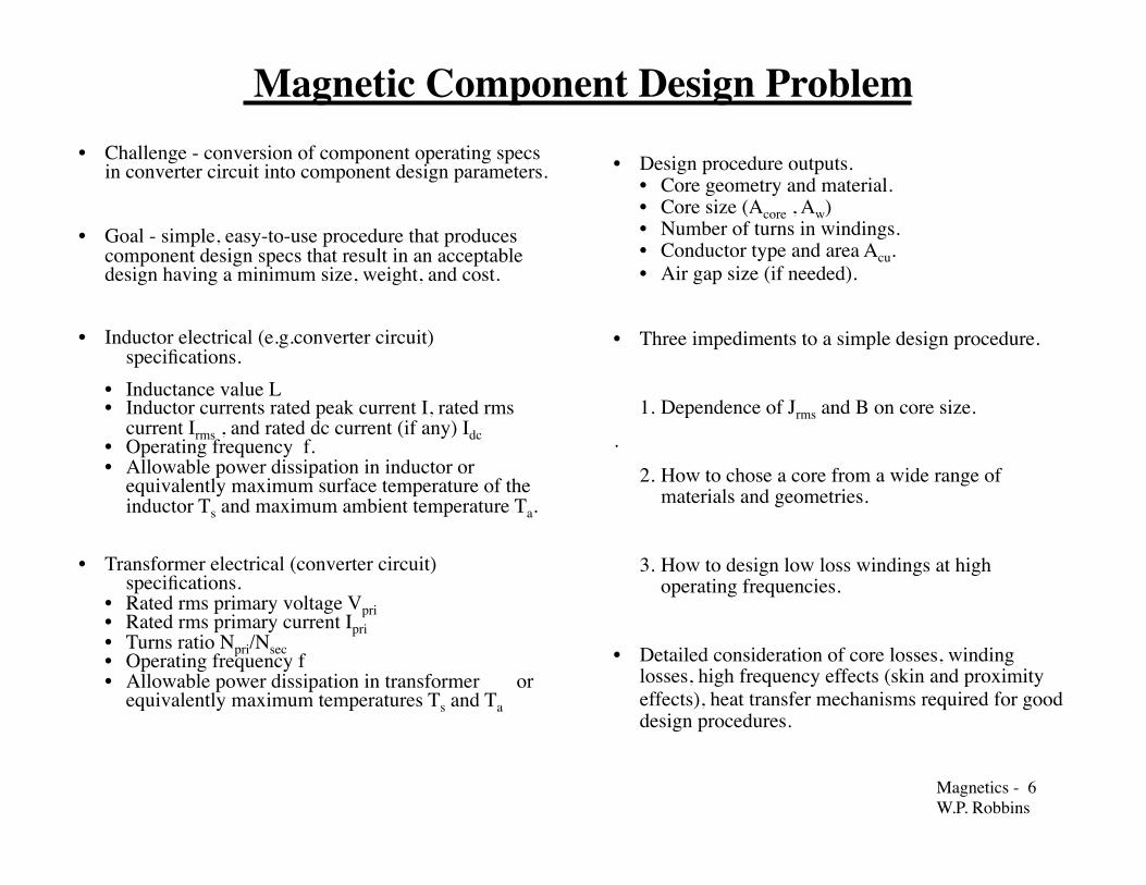
Magnetic Component Design Problem • Challenge - conversion of component operating specs in converter circuit into component design parameters.
• Goal - simple, easy-to-use procedure that produces component design specs that result in an acceptable design having a minimum size, weight, and cost.
• Inductor electrical (e.g.converter circuit) specifications. • Inductance value L • Inductor currents rated peak current I, rated rms current Irms , and rated dc current (if any) Idc • Operating frequency f. • Allowable power dissipation in inductor or equivalently maximum surface temperature of the inductor Ts and maximum ambient temperature Ta.
• Transformer electrical (converter circuit) specifications. • Rated rms primary voltage Vpri • Rated rms primary current Ipri • Turns ratio Npri/Nsec • Operating frequency f • Allowable power dissipation in transformer or equivalently maximum temperatures Ts and Ta
• Design procedure outputs. • Core geometry and material. • Core size (Acore , Aw) • Number of turns in windings. • Conductor type and area Acu. • Air gap size (if needed).
• Three impediments to a simple design procedure.
1. Dependence of Jrms and B on core size. .
2. How to chose a core from a wide range of materials and geometries.
3. How to design low loss windings at high operating frequencies.
• Detailed consideration of core losses, winding losses, high frequency effects (skin and proximity effects), heat transfer mechanisms required for good design procedures.
Magnetics - 7�W.P. Robbins
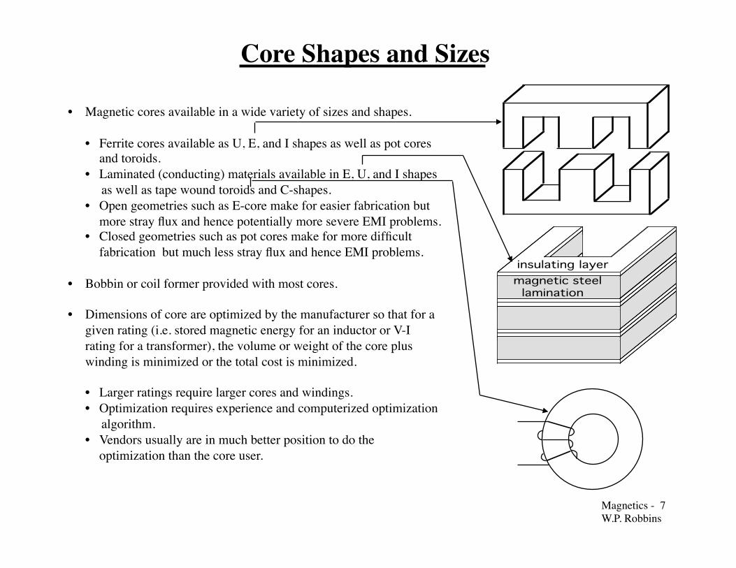
Core Shapes and Sizes
• Magnetic cores available in a wide variety of sizes and shapes.
• Ferrite cores available as U, E, and I shapes as well as pot cores and toroids. • Laminated (conducting) materials available in E, U, and I shapes
as well as tape wound toroids and C-shapes.� • Open geometries such as E-core make for easier fabrication but more stray flux and hence potentially more severe EMI problems.� • Closed geometries such as pot cores make for more difficult fabrication but much less stray flux and hence EMI problems.
• Bobbin or coil former provided with most cores.
• Dimensions of core are optimized by the manufacturer so that for a given rating (i.e. stored magnetic energy for an inductor or V-I rating for a transformer), the volume or weight of the core plus winding is minimized or the total cost is minimized.
• Larger ratings require larger cores and windings. • Optimization requires experience and computerized optimization
algorithm. • Vendors usually are in much better position to do the optimization than the core user.
magnetic steel lamination
insulating layer

Magnetics - 8�W.P. Robbins
Double-E Core Example
Characteristic Relative Size Absolute Size fora = 1 cm
Core area Acore 1.5 a2 1.5 cm2Winding area Aw 1.4 a2 1.4 cm2Area product AP = AwAc 2.1 a4 2.1 cm4Core volume Vcore 13.5 a3 13.5 cm3Winding volume Vw 12.3a3 12.3 cm3Total surface area ofassembled core andwinding
59.6 a2 59.6 cm2
h wbw
1.4 a
1.9 a
Bobbin
aa2
da2
b a
h a2
Core
Assembled core and winding

Magnetics - 9�W.P. Robbins
Types of Core Materials
• Iron-based alloys
• Various compositions• Fe-Si (few percent Si)• Fe-Cr-Mn• METGLASS (Fe-B, Fe-B-Si, plus many
other compositions)
• Important properties• Resistivity _ = (10 - 100) ρCu• Bs = 1 - 1.8 T (T = tesla = 104 oe)
• METGLASS materials available only astapes of various widths and thickness.
• Other iron alloys available as laminationsof various shapes.
• Powdered iron can be sintered intovarious core shapes. Powdered iron coreshave larger effective resistivities.
• Ferrite cores
• Various compositions - iron oxides,Fe-Ni-Mn oxides
• Important properties
• Resistivity ρ very large (insulator) -no ohmic losses and hence skineffect problems at highfrequencies.
• Bs = 0.3 T (T = tesla = 104 oe)
Magnetics - 10�W.P. Robbins
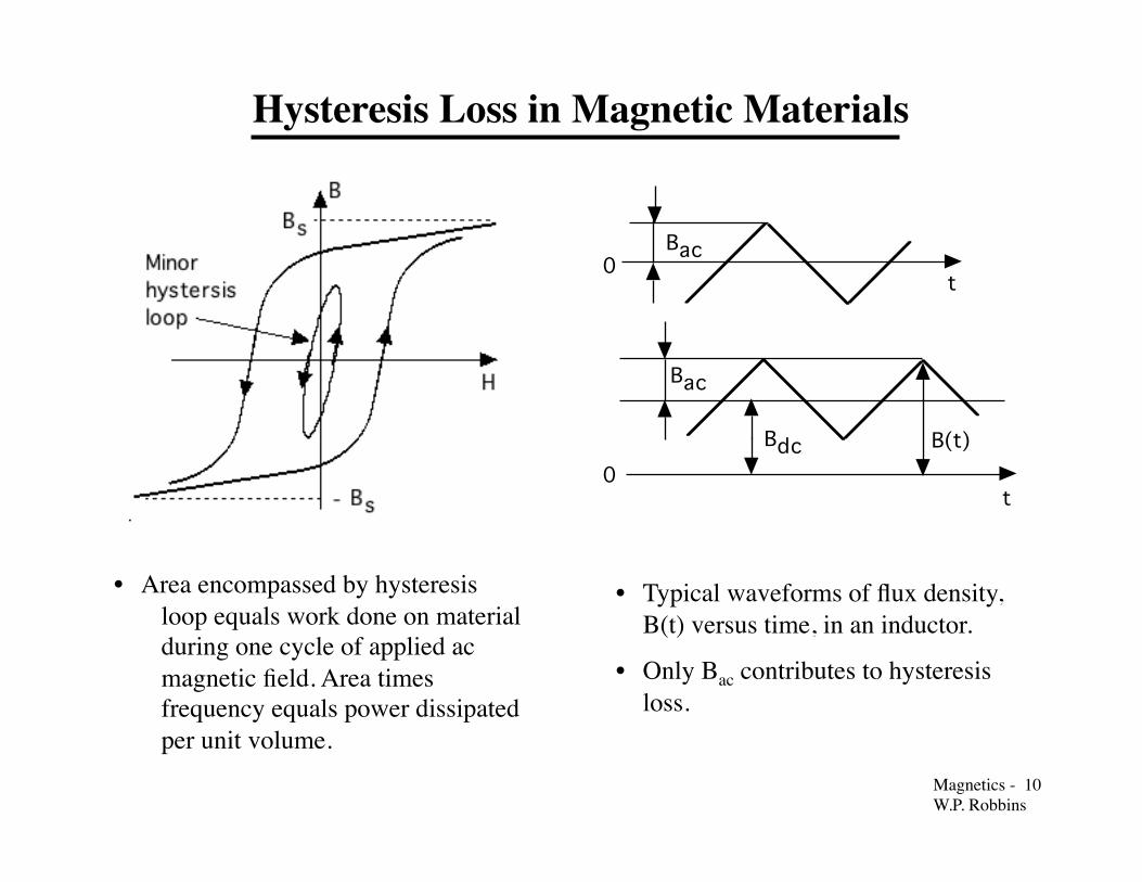
Hysteresis Loss in Magnetic Materials
t
Bac0
t0
B(t)Bdc
Bac
• Typical waveforms of flux density, B(t) versus time, in an inductor.
• Only Bac contributes to hysteresis loss.
• Area encompassed by hysteresis loop equals work done on material during one cycle of applied ac magnetic field. Area times frequency equals power dissipated per unit volume.

Magnetics - 11�W.P. Robbins
Quantitative Description of Core Losses
• Eddy current loss plus hysteresis loss =core loss.
• Empirical equation - Pm,sp = k fa [Bac]d
.f = frequency of applied field. Bac =base-to-peak value of applied ac field. k,a, and d are constants which vary frommaterial to material
• Pm,sp = 1.5x10⁻⁶ f1.3 [Bac]2.5
mW/cm3 for 3F3 ferrite. (f in kHz andB in mT)
• Pm,sp = 3.2x10⁻⁶ f1.8 [Bac]2
mW/cm3 METGLAS 2705M (f in kHzand B in mT)
• Example: 3F3 ferrite with f = 100 kHzand Bac = 100 mT, Pm,sp = 60
mW/cm3
• 3F3 core losses in graphical form.

Magnetics - 12�W.P. Robbins
Core Material Performance Factor • Volt-amp (V-A) rating of transformers proportional to f Bac
• Core materials have different allowable values of Bac at a specific frequency. Bac limted by allowable Pm,sp.
• Most desirable material is one with largest Bac.
• Choosing best material aided by defining an emperical performance factor PF = f Bac. Plots of PF versus frequency for a specified value of Pm,sp permit rapid selection of best material for an application.
• Plot of PF versus frequency at Pm,sp = 100 mW/cm3 for several different ferrites shown below.

Magnetics - 13�W.P. Robbins
Eddy Current Losses in Magnetic Cores
• AC magnetic fields generate eddy currents in conducting magnetic materials.
• Eddy currents dissipate power.
• Shield interior of material from magnetic field.
•Bi(r)Bo
= exp({r - a}/δ)
• δ = skin depth = 2ωµσ
• ω = 2π f, f = frequency• µ = magnetic permeability ; µo for magnetic materials.
• σ = conductivity of material.
• Numerical example
• σ = 0.05 σcu ; µ = 103 µo f = 100 Hz
• δ = 1 mm
Magnetics - 14�W.P. Robbins
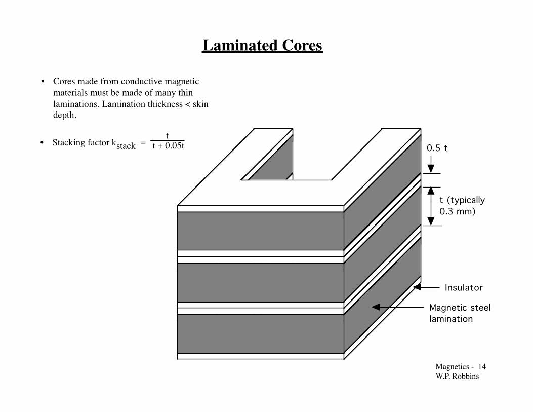
Magnetic steel lamination
Insulator
0.5 t
t (typically 0.3 mm)
Laminated Cores
• Cores made from conductive magnetic materials must be made of many thin laminations. Lamination thickness < skin depth. • Stacking factor kstack =
t t + 0.05t

Magnetics - 15�W.P. Robbins
Eddy Current Losses in Laminated Cores
x
dx
-x
L
d
w
B sin(ωt)
x
y
z
Eddy current flow path
• Flux φ(t) intercepted by current loopof area 2xw given by φ(t) = 2xwB(t)
• Voltage in current loop v(t) = 2xw dB(t)
dt= 2wxωBcos(ωt)
• Current loop resistance r = 2wρcore
L dx ; w >> d
• Instantaneous power dissipated in thin loop
δp(t) = [v(t)]2
r
• Average power Pec dissipated in lamination
given by Pec = <⌡⌠δp(t)dV > = w L d3 ω2 B2
24 ρcore
• Pec,sp = PecV =
w L d3 ω2 B2
24 ρcore
1dwL=
d2 ω2 B2
24 ρcore
• Average power Pec dissipated in lamination
given by Pec = <⌡⌠δp(t)dV > = w L d3 ω2 B2
24 ρcore
• Pec,sp = PecV =
w L d3 ω2 B2
24 ρcore
1dwL =
d2 ω2 B2
24 ρcore
Magnetics - 16�W.P. Robbins
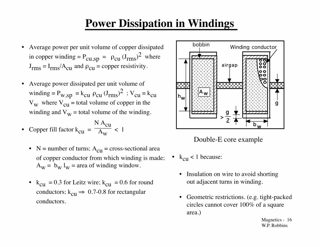
Power Dissipation in Windings
• Average power per unit volume of copper dissipatedin copper winding = Pcu,sp = ρcu (Jrms)2 whereJrms = Irms/Acu and ρcu = copper resistivity.
• Average power dissipated per unit volume ofwinding = Pw,sp = kcu ρcu (Jrms)2 ; Vcu = kcuVw where Vcu = total volume of copper in thewinding and Vw = total volume of the winding.
• Copper fill factor kcu = N Acu
Aw < 1
• N = number of turns; Acu = cross-sectional areaof copper conductor from which winding is made;Aw = bw lw = area of winding window.
• kcu = 0.3 for Leitz wire; kcu = 0.6 for roundconductors; kcu ⇒ 0.7-0.8 for rectangularconductors.
bobbin
ghw
>g2
wb
A w
ai rgap
Winding conductor
• kcu < 1 because:
• Insulation on wire to avoid shorting out adjacent turns in winding.
• Geometric restrictions. (e.g. tight-packedcircles cannot cover 100% of a squarearea.)
Double-E core example

Magnetics - 17�W.P. Robbins
B sin(ωt)
+ -- + - +
+ -
B sin(ωt)
Eddy Currents Increase Winding Losses • AC currents in conductors generate ac
magnetic fields which in turn generate eddycurrents that cause a nonuniform currentdensity in the conductor . Effective resistanceof conductor increased over dc value.• Pw,sp > kcu ρcu (Jrms)2 if conductor
dimensions greater than a skin depth.
•J(r)Jo = exp({r - a}/δ)
• δ = skin depth = 2
ωµσ• ω = 2π f, f = frequency of ac current• µ = magnetic permeability of conductor;µ = µo for nonmagnetic conductors.
• σ = conductivity of conductor material.
• Numerical example using copper at 100 °CFrequency 50
Hz5kHz
20kHz
500kHz
SkinDepth
10.6mm
1.06mm
0.53mm
0.106mm
• Mnimize eddy currents using Leitz wirebundle. Each conductor in bundle has adiameter less than a skin depth.
• Twisting of paralleled wires causes effects ofintercepted flux to be canceled out betweenadjacent twists of the conductors. Hence little ifany eddy currents.
Magnetics - 18�W.P. Robbins
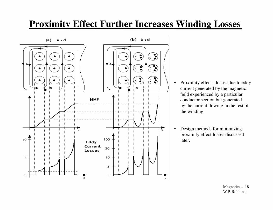
Proximity Effect Further Increases Winding Losses
• Proximity effect - losses due to eddy current generated by the magnetic field experienced by a particular conductor section but generated by the current flowing in the rest of the winding.
• Design methods for minimizing proximity effect losses discussed later.

Magnetics - 19�W.P. Robbins
Minimum Winding Loss
• Pw = Pdc + Pec ; Pec = eddy current loss.
• Pw = { Rdc + Rec} [Irms]2 = Rac [Irms]2
• Rac = FR Rdc = [1 + Rec/Rdc] Rdc
Optimum conductor size
• Minimum winding loss at optimum conductor size.
• Pw = 1.5 Pdc
• Pec = 0.5 Pdc
• High frequencies require small conductor sizes minimize loss.
• Pdc kept small by putting may small-size conductors in parallel usingLitz wire or thin but wide foil conductors.

Magnetics - 20�W.P. Robbins
Thermal Considerations in Magnetic Components • Losses (winding and core) raise core temperature. Common design practice to limit maximum interior temperature to 100-125 °C. • Core losses (at constant flux density) increase with temperature increases above 100 °C
• Saturation flux density Bs decreases with temp. Increases
• Nearby components such as power semi- conductor devices, integrated circuits, capacitors
have similar limits.
• Temperature limitations in copper windings
• Copper resistivity increases with temperature increases. Thus losses, at constant current density increase with temperature.
• Reliability of insulating materials degrade with temperature increases.
• Surface temperature of component nearly equal to interior temperature. Minimal temperature gradient between interior and exterior surface. • Power dissipated uniformly in component volume. • Large cross-sectional area and short path lengths to surface of components. • Core and winding materials have large thermal conductivity.
.• Thermal resistance (surface to ambient) of magnetic component determines its temperature.
• Psp = Ts - Ta
Rθsa(Vw + Vc) ; Rθsa = h
As
• h = convective heat transfer coefficient =10 °C-m2/W
• As = surface area of inductor (core + winding).Estimate using core dimensions and simplegeometric considerations.
• Uncertain accuracy in h and other heat transferparameters do not justify more accurate thermalmodeling of inductor.
Magnetics - 21�W.P. Robbins
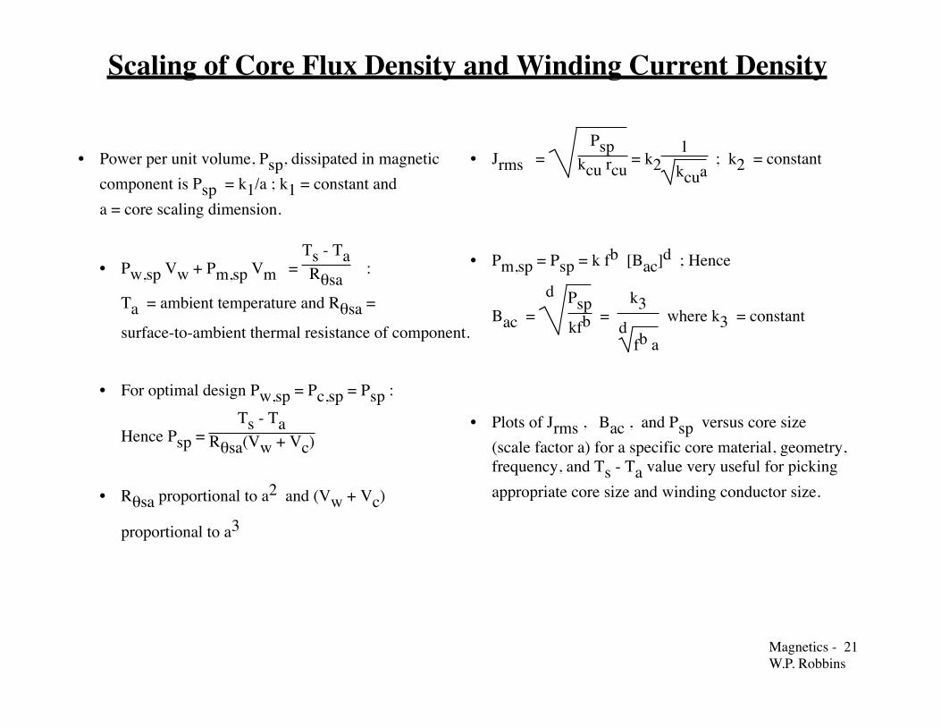
Scaling of Core Flux Density and Winding Current Density
• Power per unit volume, Psp, dissipated in magneticcomponent is Psp = k1/a ; k1 = constant anda = core scaling dimension.
• Pw,sp Vw + Pm,sp Vm = Ts - TaRθsa
:
Ta = ambient temperature and Rθsa =
surface-to-ambient thermal resistance of component.
• For optimal design Pw,sp = Pc,sp = Psp :
Hence Psp = Ts - Ta
Rθsa(Vw + Vc)
• Rθsa proportional to a2 and (Vw + Vc)
proportional to a3
• Jrms = Psp
kcu rcu = k2
1kcua
; k2 = constant
• Pm,sp = Psp = k fb [Bac]d ; Hence
Bac = d Psp
kfb =
k3d
fb a
where k3 = constant
• Plots of Jrms , Bac , and Psp versus core size(scale factor a) for a specific core material, geometry,frequency, and Ts - Ta value very useful for pickingappropriate core size and winding conductor size.

Magnetics - 22�W.P. Robbins
0
1
2
3
4
5
6
7
8
0
50
100
150
200
250
300
350
400
0.5 1 1.5 2 2.5 3 3.5 4 4.5 5
mW/cm 3A/mm 2
Core scaling parameter a [cm]
Ps p
J rms Ps p
J rms
Example of Power Density and Current Density Scaling
Assumptions
1. Double-E core made from 3F3 ferrite
2. Ts = 100 °C and Ta = 40 °C.
3. Winding made with Leitz wire - kcu = 0.3
Magnetics - 23�W.P. Robbins
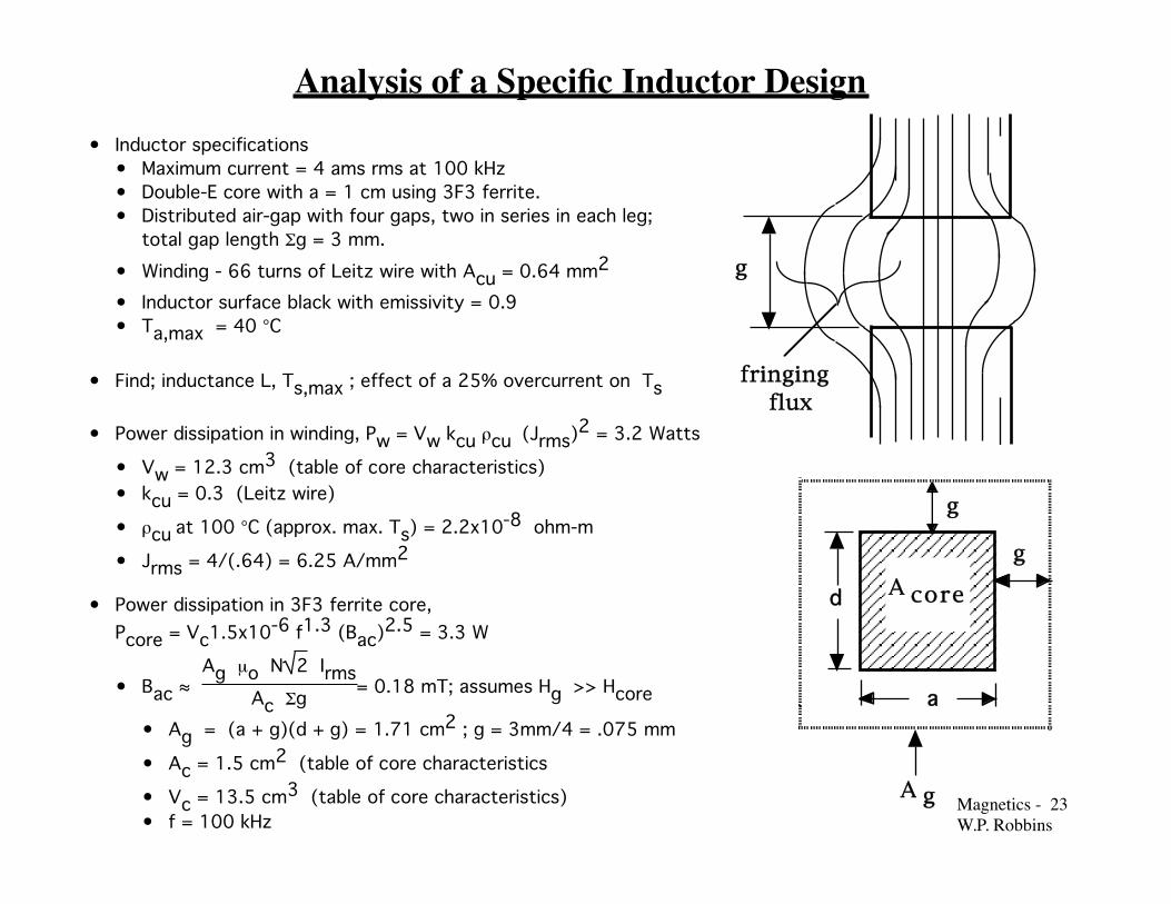
Analysis of a Specific Inductor Design • Inductor specifications
• Maximum current = 4 ams rms at 100 kHz• Double-E core with a = 1 cm using 3F3 ferrite.• Distributed air-gap with four gaps, two in series in each leg;
total gap length Σg = 3 mm.
• Winding - 66 turns of Leitz wire with Acu = 0.64 mm2
• Inductor surface black with emissivity = 0.9• Ta,max = 40 °C
fringing flux
g
g
A core
A g
g
a
d
• Find; inductance L, Ts,max ; effect of a 25% overcurrent on Ts
• Power dissipation in winding, Pw = Vw kcu ρcu (Jrms)2 = 3.2 Watts
• Vw = 12.3 cm3 (table of core characteristics)• kcu = 0.3 (Leitz wire)
• ρcu at 100 °C (approx. max. Ts) = 2.2x10⁻⁸ ohm-m
• Jrms = 4/(.64) = 6.25 A/mm2
• Power dissipation in 3F3 ferrite core,Pcore = Vc1.5x10-6 f1.3 (Bac)2.5 = 3.3 W
• Bac ≈ Ag µo N 2 Irms
Ac Σg = 0.18 mT; assumes Hg >> Hcore
• Ag = (a + g)(d + g) = 1.71 cm2 ; g = 3mm/4 = .075 mm
• Ac = 1.5 cm2 (table of core characteristics
• Vc = 13.5 cm3 (table of core characteristics)• f = 100 kHz
Magnetics - 24�W.P. Robbins
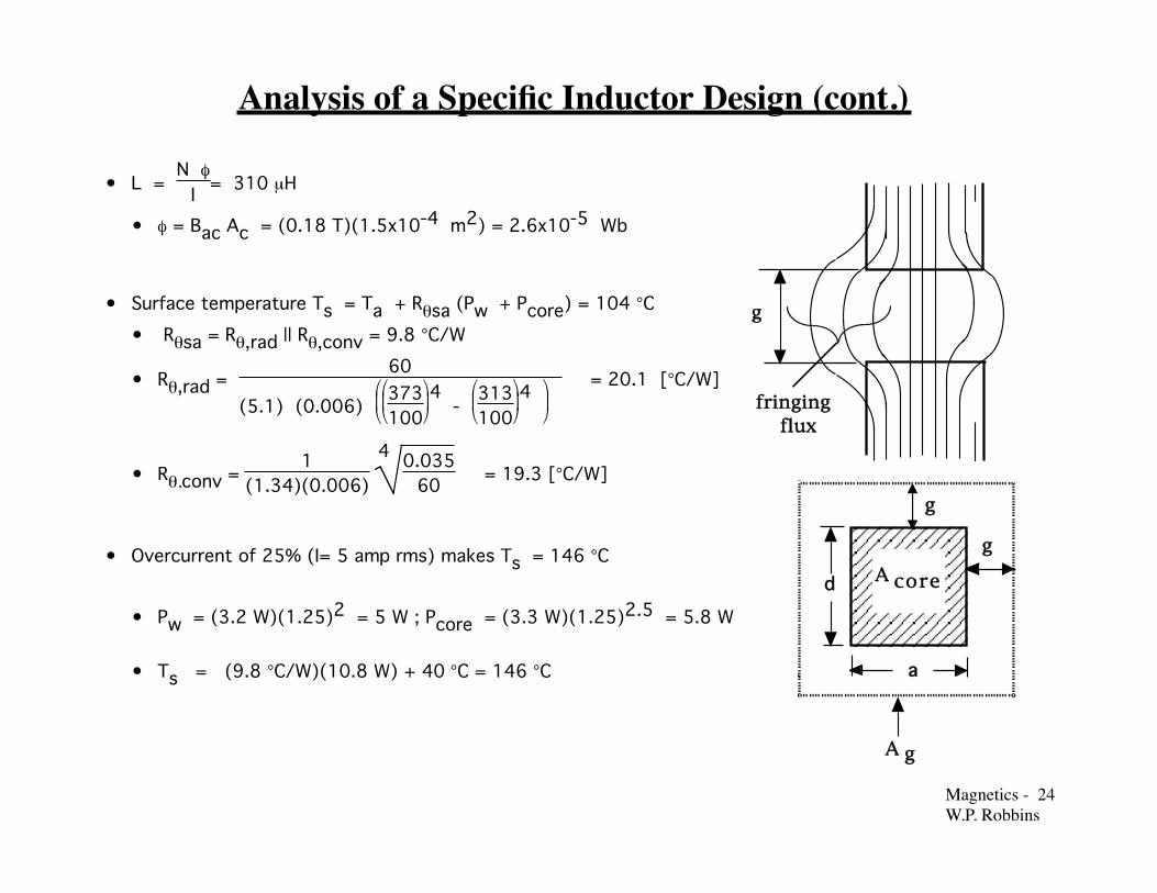
Analysis of a Specific Inductor Design (cont.)
• L = N φ
I = 310 µH
• φ = Bac Ac = (0.18 T)(1.5x10⁻⁴ m2) = 2.6x10⁻⁵ Wb
• Surface temperature Ts = Ta + Rθsa (Pw + Pcore) = 104 °C
• Rθsa = Rθ,rad || Rθ,conv = 9.8 °C/W
• Rθ,rad = 60
(5.1) (0.006)
373
1004 -
313
1004
= 20.1 [°C/W]
• Rθ,conv = 1
(1.34)(0.006) 4 0.035
60 = 19.3 [°C/W]
• Overcurrent of 25% (I= 5 amp rms) makes Ts = 146 °C
• Pw = (3.2 W)(1.25)2 = 5 W ; Pcore = (3.3 W)(1.25)2.5 = 5.8 W
• Ts = (9.8 °C/W)(10.8 W) + 40 °C = 146 °C
fringing flux
g
g
A core
A g
g
a
d
Magnetics - 25�W.P. Robbins
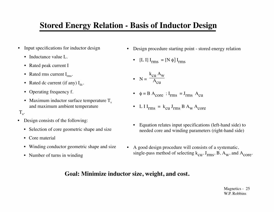
Stored Energy Relation - Basis of Inductor Design
• Design consists of the following:
• Selection of core geometric shape and size
• Core material
• Winding conductor geometric shape and size
• Number of turns in winding
• Input specifications for inductor design
• Inductance value L.
• Rated peak current I
• Rated rms current Irms.
• Rated dc current (if any) Idc.
• Operating frequency f.
• Maximum inductor surface temperature Ts � and maximum ambient temperature
Ta.
Goal: Minimize inductor size, weight, and cost.
• Design procedure starting point - stored energy relation
• [L I] Irms = [N φ] Irms
• N = kcu Aw
Acu
• φ = B Acore ; Irms = Jrms Acu
• L I Irms = kcu Jrms B Aw Acore
• Equation relates input specifications (left-hand side) toneeded core and winding parameters (right-hand side)
• A good design procedure will consists of a systematic,single-pass method of selecting kcu, Jrms, B, Aw, and Acore.

Magnetics - 26�W.P. Robbins
Core Database - Basic Inductor Design Tool
Core No. Material AP =AwAcore
RθΔT=60 °C
Psp @ΔT=60 °C
Jrms @ΔT=60 °C
& Psp
Bac @ΔT=60 °C& 100 kHz
kcu Jrms B̂ •Aw A core
• • • • • • • •8 3F3 2.1
cm49.8 °C/W 237
mW/cm33.3/ kcu 170 mT .0125 kcu
• • • • • • • •
• Interactive core database (spreadsheet-based) key to a single pass inductor design procedure. • User enters input specifications from converter design requirements. Type of conductor for windings (round wire, Leitz wire, or rectangular wire or foil) must be made so that copper fill factor kcu is known. • Spreadsheet calculates capability of all cores in database and displays smallest size core of each type that meets stored energy specification. • Also can be designed to calculate (and display as desired) design output parameters including Jrms, B, Acu, N, and air-gap length. • Multiple iterations of core material and winding conductor choices can be quickly done to aid in selection of most appropriate inductor design.
• Information on all core types, sizes, and materials must be stored on spreadsheet. Info includes dimensions, Aw, Acore, surface area of assembled inductor, and loss data for all materials of interest.
• Pre-stored information combined with user inputs to produce performance data for each core in spreadsheet. Sample of partial output shown below.
Magnetics - 27�W.P. Robbins
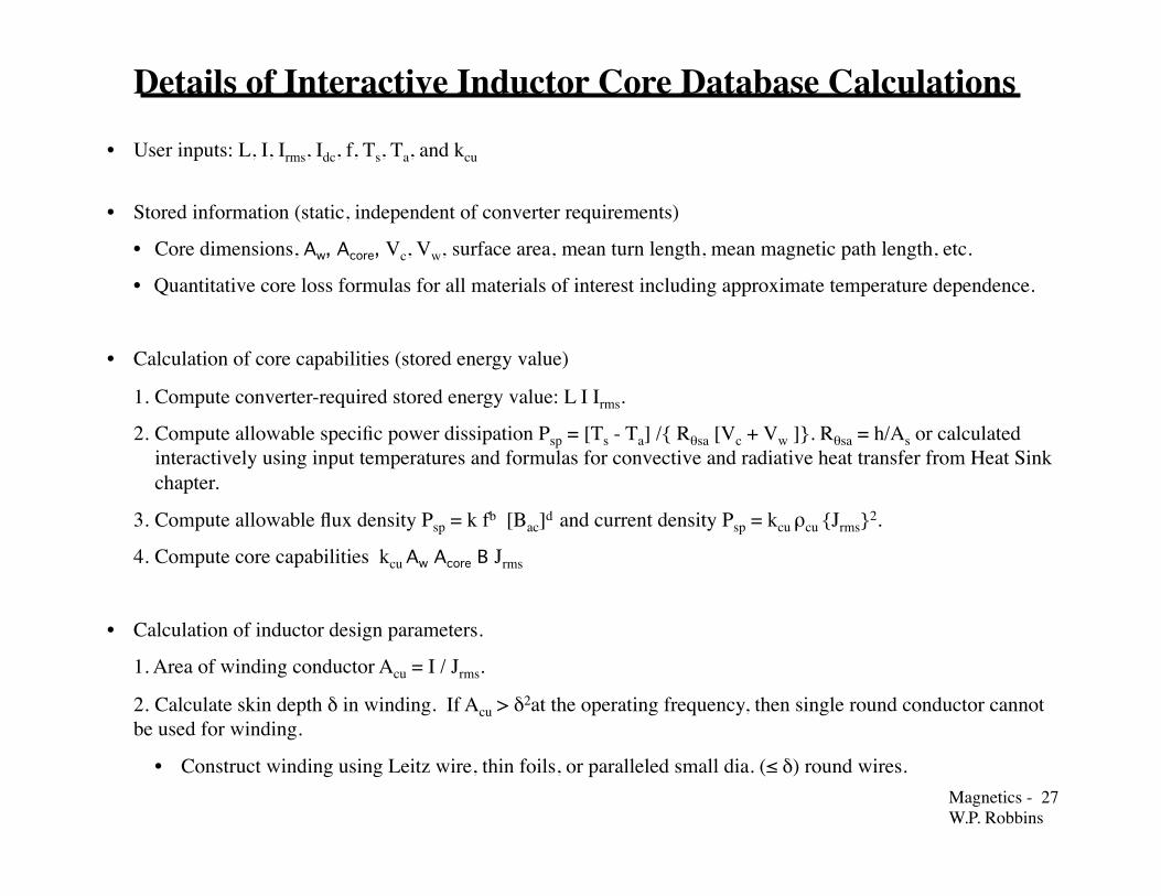
Details of Interactive Inductor Core Database Calculations
• User inputs: L, I, Irms, Idc, f, Ts, Ta, and kcu
• Stored information (static, independent of converter requirements)
• Core dimensions, Aw, Acore, Vc, Vw, surface area, mean turn length, mean magnetic path length, etc.
• Quantitative core loss formulas for all materials of interest including approximate temperature dependence.
• Calculation of core capabilities (stored energy value)
1. Compute converter-required stored energy value: L I Irms.
2. Compute allowable specific power dissipation Psp = [Ts - Ta] /{ Rθsa [Vc + Vw ]}. Rθsa = h/As or calculated interactively using input temperatures and formulas for convective and radiative heat transfer from Heat Sink chapter.
3. Compute allowable flux density Psp = k fb [Bac]d and current density Psp = kcu ρcu {Jrms}2.
4. Compute core capabilities kcu Aw Acore B Jrms
• Calculation of inductor design parameters.
1. Area of winding conductor Acu = I / Jrms.
2. Calculate skin depth δ in winding. If Acu > δ2at the operating frequency, then single round conductor cannot be used for winding.
• Construct winding using Leitz wire, thin foils, or paralleled small dia. (≤ δ) round wires.
Magnetics - 28�W.P. Robbins
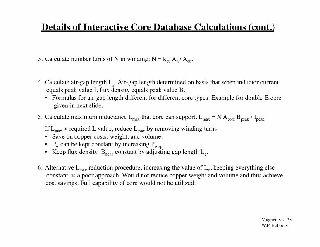
Details of Interactive Core Database Calculations (cont.)
3. Calculate number turns of N in winding: N = kcu Aw/ Acu.
4. Calculate air-gap length Lg. Air-gap length determined on basis that when inductor current equals peak value I, flux density equals peak value B. � • Formulas for air-gap length different for different core types. Example for double-E core
given in next slide.
5. Calculate maximum inductance Lmax that core can support. Lmax = N Acore Bpeak / Ipeak .
If Lmax > required L value, reduce Lmax by removing winding turns. • Save on copper costs, weight, and volume. • Pw can be kept constant by increasing Pw,sp • Keep flux density Bpeak constant by adjusting gap length Lg. 6. Alternative Lmax reduction procedure, increasing the value of Lg, keeping everything else
constant, is a poor approach. Would not reduce copper weight and volume and thus achieve cost savings. Full capability of core would not be utilized.

Magnetics - 29�W.P. Robbins
Setting Double-E Core Air-gap Length • Set total airgap length Lg so that Bpeak generated at the peak
current Ipeak.• Lg = Ng g ; Ng = number of distributed gaps each of length g.
Distributed gaps used to minimize amount of flux fringing into winding and thus causing additional eddy current losses.
• Rm = N Ipeak
Ac Bpeak = Rm,core + Rm,gap ≈ Rm,gap =
Lg
µoAg
• Lg = N Ipeak µo Ag
Ac Bpeak
• For a double-E core, Ag = (a + LgNg
) (d + LgNg
)
• Ag ≈ ad + (a + d) LgNg
; LgNg
<< a
• Insertion of expression for Ag(Lg) into expression for Lg(Ag) and solving for Lg yields
Lg = a
Bpeak Ac
d µo N Ipeak -
a + dd Ng
• Above expression for Lg only valid for double-E core, but similar expressions can be developed for other core shapes.
fringing flux
g
g
A core
A g
g
a
d

Magnetics - 30�W.P. Robbins
Enter design inputs into core database
Examine database outputs & select core
Neglect skin, proximity effects?
Yes
Select wiresIterative selection of conductor type/size.
Estimate L . Too large?
Finish
No
YesNo
Start
max
Remove turns and readjust airgap
Single Pass Inductor Design Procedure

Magnetics - 31�W.P. Robbins
Inductor Design Example
• Assemble design inputs• L = 300 microhenries• Peak current = 5.6 A,
sinewave current, Irms = 4 A• Frequency = 100 kHz• Ts = 100 °C ; Ta = 40 °C
• Stored energy L I Irms = (3x10⁻⁴)(5.6)(4)
= 0.00068 J-m-3
• Core material and geometric shape• High frequency operation dictates ferrite
material. 3F3 material has highestperformance factor PF at 100 kHz.
• Double-E core chosen for core shape.
• Double-E core with a = 1 cm meets requirements.kcu Jrms B̂ Aw Acore ≥ 0.0125 kcu 0.0068for kcu > 0.3
• Database output: Rθ = 9.8 °C/W and
Psp = 237 mW/cm3
• Core flux density B =170 mT from database.No Idc, Bpeak = 170 mT.
• Winding parameters.• Litz wire used, so kcu = 0.3. Jrms = 6 A/mm2
• Acu = (4 A)/(6 A/mm2) = 0.67 mm2
• N = (140 mm2)((0.3)/(0.67 mm2) = 63 turns.
• Lmax = (63)(170 mT)(1.5x10⁻⁴ m2)
5.6 A ≈ 290 microhenries
• Lg = 10-2
(0.17) (1.5x10⁻⁴)
(1.5x10⁻²)(4πx10-7)(63)(5.6) -
2.5x10⁻²
(4)(1.5x10⁻²) Lg ≈ 3 mm
• Lmax ≈ L so no adjustment of inductance valueis needed.

Magnetics - 32�W.P. Robbins
Iterative Inductor Design Procedure
• Iterative design procedure essentiallyconsists of constructing the coredatabase until a suitable core is found.
• Choose core material and shape andconductor type as usual.
• Use stored energy relation to find aninitial area product AwAc and thus aninitial core size.
• Use initial values of Jrms = 2-4 A/mm2
and Bac = 50-100 mT.
• Use initial core size estimate (value of a indouble-E core example) to find correctedvalues of Jrms and Bac and thus corrected value
of kcu Jrms B̂ Aw Acore.
• Compare kcu Jrms B̂ Aw Acore withL I Irms and iterate as needed into propersize is found.
Assemble design inputs
Find maximum inductance
Design airgap length g
Design winding (k ,J, A , N)cucu
Set L to design value
Start
No Yes
Select larger core size
Compute L I I rms
Choose core size using initial values of J and B
Corrected inductance-current product greater than ?
L I I rms
Find allowable power dissipation density spP
Find corrected core flux density acB
Find corrected peak core flux density B

Magnetics - 33�W.P. Robbins
Simple, Non-optimal Inductor Design Method
Assemble design inputs
Design winding (k ,J, A , N)cucu
Start
No Yes
Select larger core size
Compute L I I rms
Determine core size using assumed values of J and B
Set airgap length g to obtain desired inductance L
Check power dissipation and surface temperature. Excessive?.
Done
• Assemble design inputs and compute required LI Irms
• Choose core geometry and core material based on considerations discussed previously.
• Assume Jrms= 2-4 A/mm2 and Bac = 50-100 mT and use� LI Irms = kcu Jrms Bac Aw Acore to find the required area
product Aw Acore and thus the core size.
• Assumed values of Jrmsand Bac based on experience.
• Complete design of inductor as indicated.
• Check power dissipation and surface temperature using assumed values of Jrmsand Bac. If dissipation or temperature are excessive, select a larger core size and repeat design steps until dissipation/temperature are acceptable.
• Procedure is so-called area product method. Useful in situations where only one ore two inductors are to be built and size/weight considerations are secondary to rapid construction and testing..
Magnetics - 34�W.P. Robbins
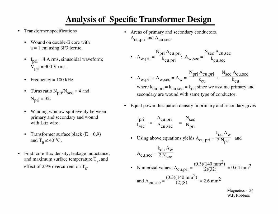
Analysis of Specific Transformer Design • Transformer specifications
• Wound on double-E core witha = 1 cm using 3F3 ferrite.
• Ipri = 4 A rms, sinusoidal waveform;Vpri = 300 V rms.
• Frequency = 100 kHz
• Turns ratio Npri/Nsec = 4 andNpri = 32.
• Winding window split evenly betweenprimary and secondary and woundwith Litz wire.
• Transformer surface black (E = 0.9)and Ta ≤ 40 °C.
• Find: core flux density, leakage inductance,and maximum surface temperature Ts, andeffect of 25% overcurrent on Ts.
• Areas of primary and secondary conductors,Acu,pri and Acu,sec.
• Aw,pri = Npri Acu,pri kcu,pri
; Aw,sec = Nsec Acu,sec kcu,sec
• Aw,pri + Aw,sec = Aw = Npri Acu,pri
kcu +
Nsec Acu,sec kcu
where kcu,pri = kcu,sec = kcu since we assume primary andsecondary are wound with same type of conductor.
• Equal power dissipation density in primary and secondary gives
IpriIsec
= Acu,pri Acu,sec
= NsecNpri
• Using above equations yields Acu,pri = kcu Aw2 Npri
and
Acu,sec = kcu Aw2 Nsec
• Numerical values: Acu,pri = (0.3)(140 mm2)
(2)(32) = 0.64 mm2
and Acu,sec = (0.3)(140 mm2)
(2)(8) = 2.6 mm2

Magnetics - 35�W.P. Robbins
Analysis of Specific Transformer Design (cont.)
• Power dissipation in winding Pw = kcu ρcu(Jrms)2 Vw
• Jrms = (4 A)/(0.64 mm2) = (16 A)/(2.6 mm2) = 6.2 A/mm2
• Pw = (0.3)(2.2x10⁻⁸ ohm-m) (6.2x10⁶ A/m2)2(1.23x10-5 m3)Pw = 3.1 watts
• Flux density and core loss
• Vpri,max = Npri Ac ω Bac = (1.414)(300) = 425 V
• Bac = 425
(32)(1.5x10⁻⁴ m2)(2π)(105 Hz)= 0.140 T
• Pcore = (13.5 cm3)(1.5x10⁻⁶)(100 kHz)1.3(140 mT)2.5 = 1.9 W
• Leakage inductance Lleak = µo(Npri)
2 bw lw3 hw
• lw = 8 a = 8 cm
• Lleak = (4πx10-7)(32)2(0.7)(10-2)(8x10⁻²)
(3)(2x10⁻²) ≈ 12 microhenries
1.4 a1.9 a
radi us = b /2wTop view of bobbin
wl = (2)(1.4a) + (2)(1.9a) + 2π (0.35b ) = 8 aw
Mean turn length l w
b = 0.7aw
• Surface temperature Ts.• Assume Rθ,sa ≈ 9.8 °C/W.
Same geometry as inductor.• Ts = (9.8)(3.1 + 1.9) + 40 = 89 °C
• Effect of 25% overcurrent.• No change in core flux density.
Constant voltage applied toprimary keeps flux density constant.
• Pw = (3.1)(1.25)2 = 4.8 watts•` Ts = (9.8)(4.8 + 1.9) + 40 = 106 °C

Magnetics - 36�W.P. Robbins
Sectioning of Transformer Windings to Reduce Winding Losses
• Reduce winding losses by reducing magnetic field (or equivently the mmf) seen by conductors in winding. Not possible in an inductor.
• Simple two-section transformer winding situation.
• Division into multiple sections reduces MMF and hence eddy current losses.
Magnetics - 37�W.P. Robbins
0.6
1
10
100
500
0.1 1 10
Normalized Power Dissipation
h/!
m = 1
m = 2
m = 3
m = 4
m = 5
m = 6
m = 7m = 8m = 9
m = 10
m = 12
m = 14
m = 16m = 18m = 20
R / R
ac
dc,h=!
dc loss
Locus ofminimum tota l loss = 1 .5 dc loss
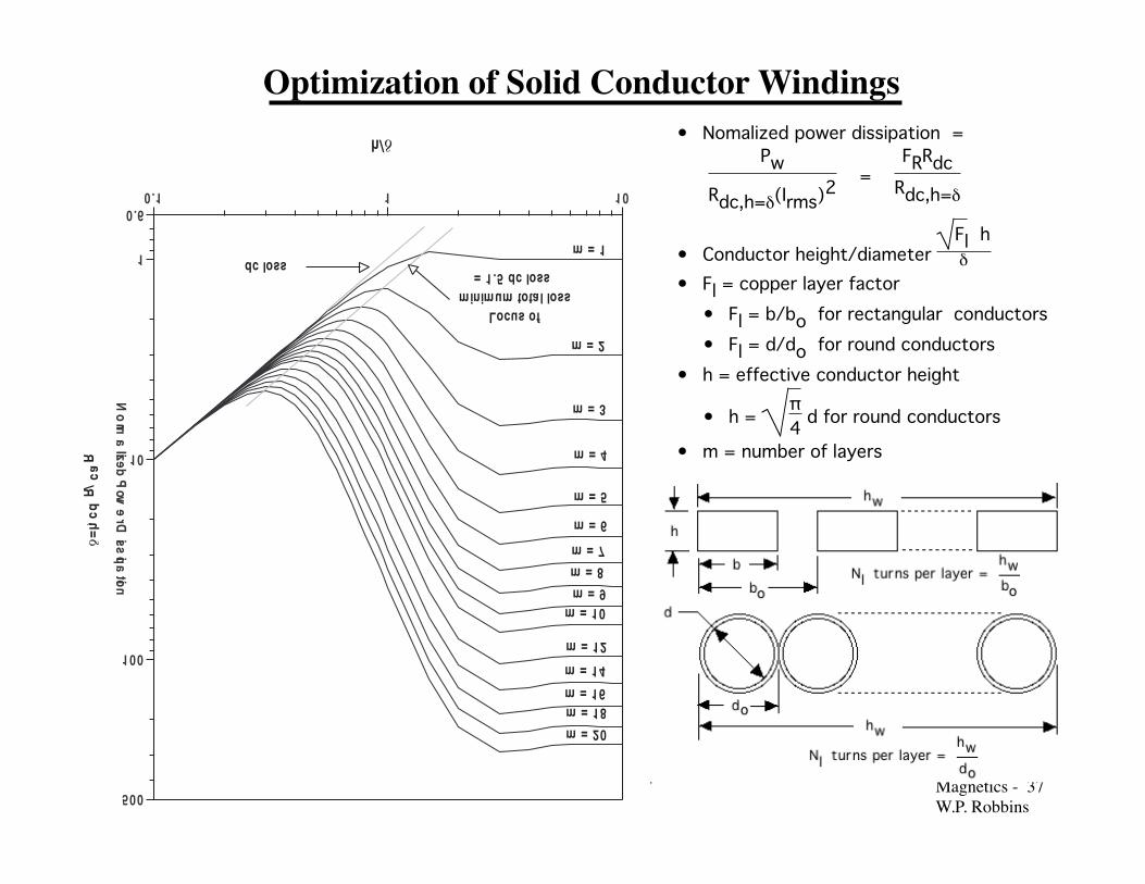
Optimization of Solid Conductor Windings • Nomalized power dissipation =
Pw
Rdc,h=δ(Irms)2 =
FRRdcRdc,h=δ
• Conductor height/diameter Fl hδ
• Fl = copper layer factor• Fl = b/bo for rectangular conductors• Fl = d/do for round conductors
• h = effective conductor height
• h = π4 d for round conductors
• m = number of layers
Magnetics - 38�W.P. Robbins
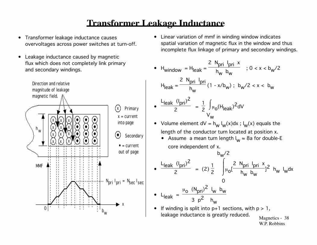
Transformer Leakage Inductance • Linear variation of mmf in winding window indicates
spatial variation of magnetic flux in the window and thusincomplete flux linkage of primary and secondary windings.
• Hwindow = Hleak = 2 Npri Ipri x
hw bw ; 0 < x < bw/2
Hleak = 2 Npri Ipri
hw (1 - x/bw) ; bw/2 < x < bw
•Lleak (Ipri)
2
2 = 12 ⌡
⌠
Vw
µo(Hleak)2dV
• Volume element dV = hw lw(x)dx ; lw(x) equals thelength of the conductor turn located at position x.• Assume a mean turn length lw ≈ 8a for double-E
core independent of x.
•Lleak (Ipri)
2
2 = (2) 12
⌡⌠
0
bw/2
µo[2 Npri Ipri x
hw bw]2 hw lwdx
• Lleak = µo (Npri)
2 lw bw
3 p2 hw• If winding is split into p+1 sections, with p > 1,
leakage inductance is greatly reduced.
• Transformer leakage inductance causesovervoltages across power switches at turn-off.
• Leakage inductance caused by magneticflux which does not completely link primaryand secondary windings.
Magnetics - 39�W.P. Robbins
Volt-Amp (Power) Rating - Basis of Transformer Design
• Design consists of the following:
• Selection of core geometric shape and size
• Core material
• Winding conductor geometric shape and size
• Number of turns in primary and secondary windings.
• Design proceedure starting point - transformer V-A rating S
• S = Vpri Ipri + Vsec Isec = 2 Vpri Ipri
• Vpri = Npri dφdt =
Npri Acore ω Bac2
; Ipri = Jrms Acu,pri
• S = 2 Vpri Ipri = 2 Npri Acore ω Bac
2 Jrms Acu,pri
• Acu,pri = kcu Aw2 Npri
• S = 2 Vpri Ipri = 2 Npri Acore ω Bac
2 Jrms
kcu Aw2 Npri
• S = Vpri Ipri = 4.4 kcu f Acore Aw Jrms Bac
• Equation relates input specifications (left-hand side) to core and winding parameters (right-hand side).
• Desired design procedure will consist of a systematic,single-pass method of selecting kcu, Acore, Aw, Jrms, and Bac.
• Input design specifications
• Rated rms primary voltage Vpri
• Rated rms primary current Ipri
• Turns ratio Npri/Nsec
• Operating frequency f
• Maximum temperatures Ts and Ta
Magnetics - 40�W.P. Robbins
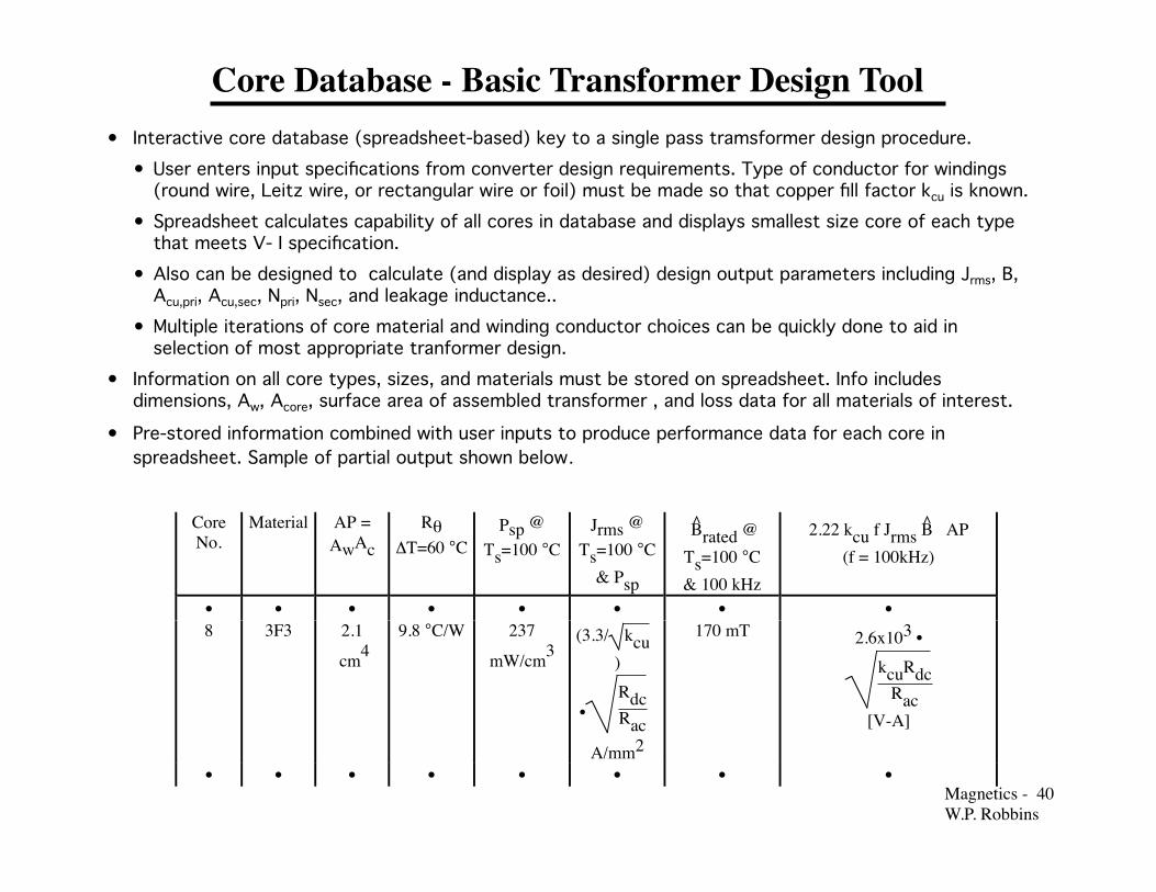
Core Database - Basic Transformer Design Tool • Interactive core database (spreadsheet-based) key to a single pass tramsformer design procedure.
• User enters input specifications from converter design requirements. Type of conductor for windings (round wire, Leitz wire, or rectangular wire or foil) must be made so that copper fill factor kcu is known. • Spreadsheet calculates capability of all cores in database and displays smallest size core of each type that meets V- I specification. • Also can be designed to calculate (and display as desired) design output parameters including Jrms, B, Acu,pri, Acu,sec, Npri, Nsec, and leakage inductance.. • Multiple iterations of core material and winding conductor choices can be quickly done to aid in selection of most appropriate tranformer design.
• Information on all core types, sizes, and materials must be stored on spreadsheet. Info includes dimensions, Aw, Acore, surface area of assembled transformer , and loss data for all materials of interest.
• Pre-stored information combined with user inputs to produce performance data for each core in spreadsheet. Sample of partial output shown below.
CoreNo.
Material AP =AwAc
RθΔT=60 °C
Psp @Ts=100 °C
Jrms @Ts=100 °C
& Psp
B̂rated @Ts=100 °C& 100 kHz
2.22 kcu f Jrms B̂ AP(f = 100kHz)
• • • • • • • •8 3F3 2.1
cm49.8 °C/W 237
mW/cm3(3.3/ kcu
)
•RdcRac
A/mm2
170 mT 2.6x10³ •kcuRdc
Rac[V-A]
• • • • • • • •

Magnetics - 41�W.P. Robbins
Details of Interactive Transformer Core Database Calculations
• User inputs: Vpri, Ipri, turns ratio Ndc/ Nsec, f, Ts, Ta, and kcu
• Stored information (static, independent of converter requirements)
• Core dimensions, Aw, Acore, Vc, Vw, surface area, mean turn length, mean magnetic path length, etc.
• Quantitative core loss formulas for all materials of interest including approximate temperature dependence.
• Calculation of core capabilities
1. Compute converter-required stored energy value: S = 2 Vpri Ipri
2. Compute allowable specific power dissipation Psp = [Ts - Ta] /{ Rθsa [Vc + Vw ]}. Rθsa = h/As or calculated interactively using input temperatures and formulas for convective and radiative heat transfer from Heat Sink chapter.
3. Compute allowable flux density Psp = k fb [Bac]d and current density Psp = kcu ρcu {Jrms}2.
4. Compute core capabilities 4.4 f kcu Aw Acore Bac Jrms
• Calculation transformer parameters.
1. Calculate number of primary turns Npri = Vpri /{2π f AcpreBac} and secondary turns Nsec = Vsec /{2π f AcpreBac}
2. Calculate winding conductor areas assuming low frequencies or use of Leitz wire
• Acu,pri = [kcuAw]/[2 Npri] and Acu,sec = [kcuAw]/[2 Nsec]

Magnetics - 42�W.P. Robbins
Details of Interactive Transformer Core Database Calculations (cont.)
3. Calculate winding areas assuming eddy current/proximity effect is important
• Only solid conductors, round wires or rectangular wires (foils), used.Jrms = [{Psp Rdc}/{Rac kcu rcu}]1/2
• Conductor dimensions must simultaneously satisfy area requirements and requirements of normalized power dissipation versus normalized conductor dimensions. • May require change in choice of conductor shape. Most likely will require choice of foils (rectangular
shapes). • Several iterations may be needed to find proper combinations of dimensions, number of turns per layer,
and number of layers and sections. • Best illustrated by a specific design example.
4. Estimate leakage inductance Lleak= {µo{Npri}2 lw bw}/ {3 p2 hw}
5. Estimate Smax = 4.4 kcu f Acore Aw Jrms Bac
6. If Smax > S = 2 Vpri Ipri reduce Smax and save on copper cost, weight, and volume. • If Npri w Ac Bac > Vpri, reduce Smax by reducing Npri and Nsec. • If Jrms Acu, pri > Irms, reduce Acu,pri and Acu, sec. • If S > Smax by only a moderate amount (10-20%) and smaller than Smax of next core size, increase Smax of
present core size. • Increase Irms (and thus winding power dissipation) as needed.Temperature Ts will increase a modest amount
above design limit, but may be preferable to going to larger core size.
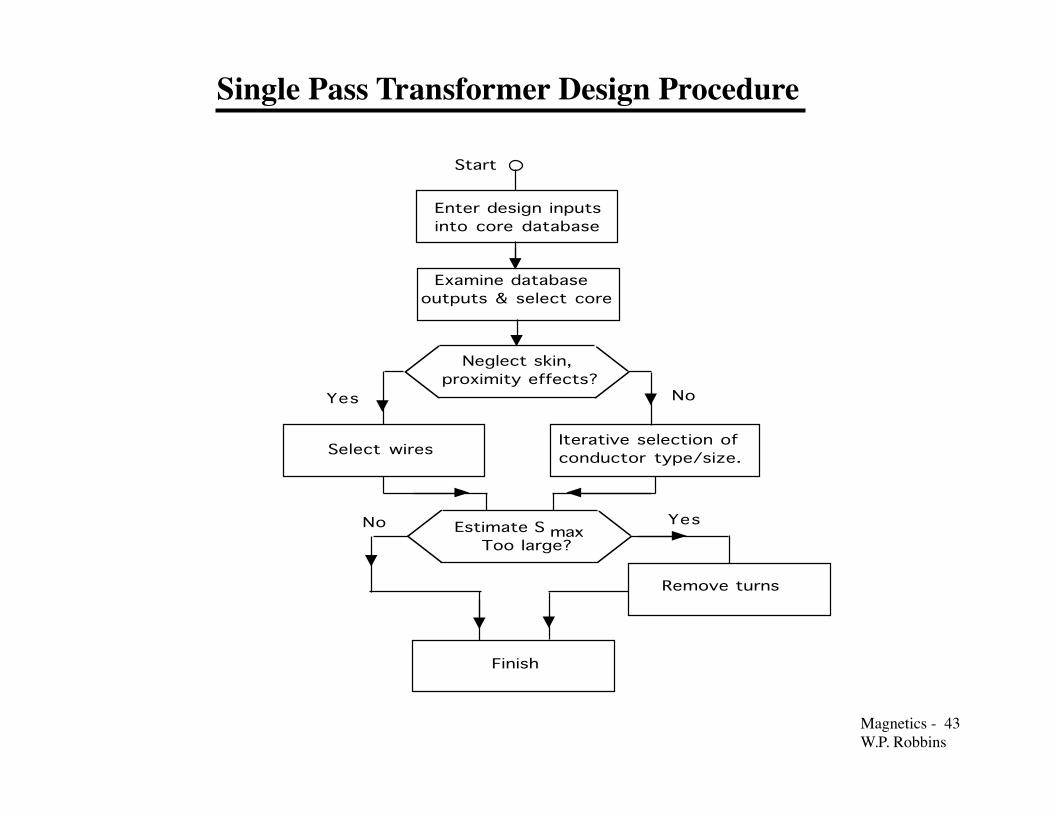
Magnetics - 43�W.P. Robbins
Enter design inputs into core database
Examine database outputs & select core
Neglect skin, proximity effects?
Yes
Select wiresIterative selection of conductor type/size.
Estimate S . Too large?
Finish
No
YesNo
Start
max
Remove turns
Single Pass Transformer Design Procedure

Magnetics - 44�W.P. Robbins
Transformer Design Example • Using core database, Rθ = 9.8 °C/W
and Psp = 240 mW/cm3.
• Flux density and number of primaryand secondary turns.• From core database, Bac = 170 mT.
• Npri = 300 2
(1.5x10⁻⁴m2)(2π)(105Hz)(0.17 T)= 26.5 ≈ 24. Rounded down to 24 to increaseflexibility in designing sectionalizedtransformer winding.
• Nsec = 246 = 6.
• Design inputs• Vpri = 300 V rms ; Irms = 4 A rms• Turns ratio n = 4• Operating frequency f = 100 kHz• Ts = 100 °C and Ta = 40 °C
• V - I rating S = (300 V rms)(4 A rms)= 1200 watts
• Core material, shape, and size.• Use 3F3 ferrite because it has largest
performance factor at 100 kHz.• Use double-E core. Relatively easy to
fabricate winding.
• Core volt-amp rating = 2,600 kcuRdcRac
• Use solid rectangular conductor forwindings because of high frequency.Thus kcu = 0.6 and Rac/Rdc = 1.5.
• Core volt-amp capability = 2,600 0.61.5
= 1644 watts. > 1200 watt transformer rating.Size is adequate.
• From core database Jrms = 3.3
(0.6)(1.5)
= 3.5 A/mm2.
• Acu,pri = 4 A rms
3.5 A rms/mm2 = 1.15 mm2
• Acu,sec = (4)(1.15 mm2) = 4.6 mm2
Magnetics - 45�W.P. Robbins
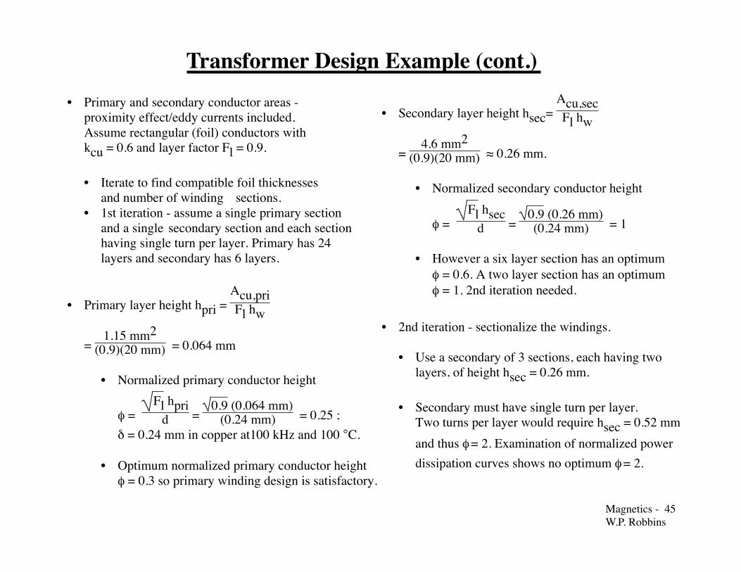
Transformer Design Example (cont.) • Primary and secondary conductor areas -
proximity effect/eddy currents included.Assume rectangular (foil) conductors withkcu = 0.6 and layer factor Fl = 0.9.
• Iterate to find compatible foil thicknessesand number of winding sections.
• 1st iteration - assume a single primary sectionand a single secondary section and each sectionhaving single turn per layer. Primary has 24layers and secondary has 6 layers.
• Primary layer height hpri = Acu,priFl hw
= 1.15 mm2
(0.9)(20 mm) = 0.064 mm
• Normalized primary conductor height
φ = Fl hpri
d = 0.9 (0.064 mm)
(0.24 mm) = 0.25 ;δ = 0.24 mm in copper at100 kHz and 100 °C.
• Optimum normalized primary conductor heightφ = 0.3 so primary winding design is satisfactory.
• Secondary layer height hsec= Acu,secFl hw
= 4.6 mm2
(0.9)(20 mm) ≈ 0.26 mm.
• Normalized secondary conductor height
φ = Fl hsec
d = 0.9 (0.26 mm)(0.24 mm) = 1
• However a six layer section has an optimum φ = 0.6. A two layer section has an optimumφ = 1. 2nd iteration needed.
• 2nd iteration - sectionalize the windings.
• Use a secondary of 3 sections, each having twolayers, of height hsec = 0.26 mm.
• Secondary must have single turn per layer.Two turns per layer would require hsec = 0.52 mmand thus φ = 2. Examination of normalized powerdissipation curves shows no optimum φ = 2.

Magnetics - 46�W.P. Robbins
Transformer Design Example (cont.)
P6
S3
P3
P3
S3
S3
P6
• Three secondary sections requires four primary sections.
• Two outer primary sections would have 24/6 = 4turns each and the inner two sections would have24/3 = 8 turns each.
• Need to determine number of turns per layer andhence number of layers per section.
Turns/layer
hpri No. ofLayers
φ Optimumφ
1 0.064 mm 8 0.25 0.452 0.128 mm 4 0.5 0.64 0.26 mm 2 1 1
• Use four turns per layer. Two interior primarysections have two layers and optimum value of φ.
Two outer sections have one layer each and φ notoptimum, but only results in slight increase in lossabove the minimum.
• Leakage inductance Lleak
= (4πx10-9)(24)2(8)(0.7)(1)
(3)(6)2(2) = 0.2 µH
• Sectionalizing increases capacitancebetween windings and thus lowers thetransformer self-resonant frequency.
• Smax = 1644 watts
• Rated value of S = 1200 watts onlymarginally smaller than Smax. Little tobe gained in reducing Smax to S unless alarge number of transformer of this designare to be fabricated.

Magnetics - 47�W.P. Robbins
Assemble design inputs
Find maximum V - I rating
Estimate leakage inductance
Start
No Yes
Select larger core size
Choose core size using initial values of J and B
Find allowable power dissipation density spP
Find corrected core flux density acB
Compute 2 V Ipripri
Find corrected current density Jrms
Design windings ( cu,priAcu,secA
priNsecN
,,
,)
Corrected V-I rating greater than 2 V I ?pripri
Set S to desired Smax
End
Iterative Transformer Design Procedure • Iterative design procedure essentially
consists of constructing the coredatabase until a suitable core is found.
• Choose core material and shape andconductor type as usual.
• Use V - I rating to find an initial areaproduct AwAc and thus an initial core size.
• Use initial values of Jrms = 2-4 A/mm2
and Bac = 50-100 mT.
• Use initial core size estimate (value of a indouble-E core example) to find correctedvalues of Jrms and Bac and thus corrected
value of 4.4 f kcu Jrms B̂ Aw Acore.
• Compare 4.4 f kcu Jrms B̂ Aw Acore with2 Vpri Ipri and iterate as needed into propersize is found.

Magnetics - 48�W.P. Robbins
Simple, Non-optimal Transformer Design Method
Assemble design inputs
Start
No Yes
Select larger core size
Determine core size using assumed values of J and B
Check power dissipation and surface temperature. Excessive?.
Done
Compute 2 V Ipri pri
NpriDesign winding ( A cu,priAcu,sec Nsec,
, ,)
Set S to desired Smax
• Assemble design inputs and compute required 2 Vpri Ipri
• Choose core geometry and core material based on considerations discussed previously.
• Assume Jrms= 2-4 A/mm2 and Bac = 50-100 mT and use� 2 Vpri Ipri = 4.4 f kcu Jrms Bac Aw Acore to find the required area
product Aw Acore and thus the core size.
• Assumed values of Jrmsand Bac based on experience.
• Complete design of transformer as indicated.
• Check power dissipation and surface temperature using assumed values of Jrmsand Bac. If dissipation or temperature are excessive, select a larger core size and repeat design steps until dissipation/temperature are acceptable.
• Procedure is so-called area product method. Useful in situations where only one ore two transformers are to be built and size/weight considerations are secondary to rapid construction and testing..