design of lock gates for ship collision
TRANSCRIPT

Version 3 – PIANC Short Course – 8th Sept 2015
Ship collision against lock gates
PIANC SHORT COURSE SMART RIVERS 2015, Argentina, Buenos Aires, 8th September 2015
Table of content
1) Introduction: Aims of PIANC WG 151 in terms of ship collision against
lock gates (20 min)
By Prof. Philippe RIGO, University of Liège (BE); INCOM Chairman ‐
2) Presentation of the WG 151 report: Design of lock gates for ship collision (45 min)
By Juan OLLERO, Inros‐Lackner AG (Germany) ‐ Juan.Ollero@inros‐lackner.de
Presentation of the data that have to be collected to correctly define the collision scenario
Brief review of the existing types of lock gates
Presentation of some impact protection systems
Description of the current practice and philosophy in different countries to protect lock
gates against ship collisions
Review of the potential consequences in case of impact
Presentation of four different methodologies to evaluate the crashworthiness:
o The CETMEF approach
o The analytical approach
o The numerical methods
o The use of physical models
Conclusion: recommended assessment procedure
3) Presentation of the experience of Panama (ACP) “How was considered ship collision in the design of
the new lock gates” (15 min)
By Johnny WONG, and Rogelio GORDON; ACP, Panama
[email protected] , [email protected]
4) Presentation of new advanced analytical methods to assess crashworthiness of lock gates (2 x 45 min)
By Dr. L. Buldgen: University of Liège (BE), [email protected]
Presentation of advanced analytical methods to evaluate the collision resistance for plane
lock gates
o Local deforming mode
o Global deforming mode
Extension of the simplified method to mitre lock gates
Validation of the analytical results with numerical solutions
o Description of the finite element models (LS‐DYNA)
o Comparison of the resistance and energy curves
Current development:
o Extension to double hull gates (as wheelbarrow rolling gates)
o Extension to impact on offshore wind structure (jacket and monopoles of wind
turbines)

PIANC SHORT COURSE
Design of lock gates for ship collision
(InCom WG151 report)
PIANC Smart Rivers Conference, September 2015, Buenos Aires
PIANC InCom WG 151
Design for lock gates for ship collision
ObjectiveWG151 was set up under the auspices of INCOM with the aim of defininggood practice and appropriate methodologies for the analysis and design oflock gates subjected to ship collision.
Members of WG 151Dr. Sören EHLERS (Chairman of Ship Collision Section)M. Juan OLLERODr. Hervé Le SOURNEDr. Loïc BULDGENDr. Ryszard DANIEL
Colin ROBERTSON (Chair of WG151)Prof. Philippe RIGO (Mentor)
PIANC InCom WG 151 - Design for lock gates for ship collision
VIDEO
Juan OLLERO, Inros-Lackner AG
PIANC InCom WG 151 - Design for lock gates for ship collision
The Speakers
Introduction: Prof. Philippe RIGO, Univ. of Liège; INCOM Chairman
Presentation of the WG 151 report: Juan OLLERO, Inros-Lackner AG (Germany) –
Experience of Panama (ACP) J. WONG, and R. GORDON; ACP, Panama
Advanced analytical methods to assess crashworthiness of lock gates Dr. L. Buldgen: University of Liège (BE),

PIANC InCom WG 151 - Design for lock gates for ship collision
Introduction
PIANC WG 151 - Ship collision against lock gates
Prof. Philippe RIGO,
University of Liège (BE); INCOM Chairman [email protected]
PIANC InCom WG 151 - Design for lock gates for ship collision
Agenda - Timing
2:15 pm : Presentation of the WG 151 report: Juan OLLERO, Inros-Lackner AG (Germany) –
3:00 pm Experience of Panama (ACP) J. WONG, and R. GORDON; ACP, Panama
3:30 BREAK
4:00 pm Advanced analytical methods to assess crashworthiness of lock gates Dr. L. Buldgen: University of Liège (BE),
5:30 pm Discussion with the floor

PIANC InCom WG 151 - Design for lock gates for ship collision
Presentation of the INCOM WG151 report
By Juan OLLERO, Inros-Lackner AG (Germany)
Brief review of the existing types of lock gates Presentation of some impact protection systems Alternatives to the installation of protection devices Design Criteria Risk Analysis Determination of the Collision Force Presentation of four different methodologies to evaluate the
crashworthiness:o The CETMEF approacho The analytical approacho The numerical methodso The use of physical models
Conclusion: recommended assessment procedure
PIANC InCom WG 151 - Design for lock gates for ship collision
Considerations of Ship Collision in the Design of New Lock Gates for the Panama Canal Expansion Project
By Johnny WONG and Rogelio GORDON, ACP, Panama
- DESIGN REQUIREMENTS- MODEL SET-UP (FEA)- RESULTS OF SHIP COLLISION ANALYSIS- CONCLUSIONS & RECOMMENDATIONS

PIANC InCom WG 151 - Design for lock gates for ship collision
Advanced analytical methods to assess crashworthiness of lock gates
By Dr. L. Buldgen: University of Liège (BE)
• Advanced analytical methods to assess collision resistance for plane lock gates
- Local deforming mode- Global deforming mode
•Extension of the simplified method to mitre lock gates
•Validation of the analytical results with numerical solutions•Description of the finite element models (LS-DYNA)•Comparison of the resistance and energy curves
•Current development:•Extension to double hull gates (as wheelbarrow rolling gates)•Extension to impact on offshore wind structure (jacket and monopoles of wind turbines)
PIANC InCom WG 151 - Design for lock gates for ship collision

PIANC InCom WG 151 - Design for lock gates for ship collision
HAVE A NICE SHORT COURSE
Do not hesitate to ask questionsat any time

Presentation of the WG 151 reportDesign of lock gates for ship collisionJuan Ollero
PIANC Smart Rivers Conference,07 – 11 September 2015, Buenos Aires
Design of Lock Gates for Ship Collision
PIANC InCom WG 151 Brief review of the existing types of lock gates Presentation of some impact protection systems Alternatives to the installation of protection devices Design Criteria Risk Analisys Determination of the Collision Force Presentation of four different methodologies to evaluate the
crashworthiness:o The CETMEF approacho The analytical approacho The numerical methodso The use of physical models
Conclusion: recommended assessment procedure

PIANC InCom WG 151
Design for lock gates for ship collision
ObjectiveWG151 was set up under the auspices of INCOM with the aim of defininggood practice and appropriate methodologies for the analysis and design oflock gates subjected to ship collision.
Members of WG 151
Professor Philippe RIGO (Mentor)Colin ROBERTSON (Chairman)Dr. Sören EHLERSDr. Hervé Le SOURNEDr. Loïc BULDGENDr. Ryszard A. DANIELJuan OLLERO
Funktion eines Schleusentores
Types of Navigation Locks
Navigation locks for inland waterwaysWidth 12,50 m ….. 25,00 m
Sea navigation locksWidth 32,00 m ….. 70,00 m
Function of a gate system
• A closure structure for a navigation lock• Part of a water regulation system• Part of a flood protection system• Closure structure of a harbour or shipyard dock.

Types of Navigation Lock Gates
Gates rotating on a vertical axis
Mitre Gates Sector Gates
Types of Navigation Lock Gates
Gates rotating on a horizontal axis
Floor-mounted flap gate Rising sector gate

Types of Navigation Lock Gates
Gates with vertical translation movement
Lifting gate system
Types of Navigation Lock Gates
Gates with horizontal translation movement
Sliding Gate System

Provisions and precautions
Provisions and precautions against ship collision
1. Installation of a protection system
2. Design of the lock gate structure to allow for the absorption of a certain impact energy
Provisions and precautions
Protection Systems (1)
• Objective: Protection of the vessel• DIN 19704 prescribes the use of protection systems• Loads according to DIN 19703• Installation within the lock chamber in front of the lower head gate
upstream
downstream
upper head open lower head close
Protection device

Provisions and precautions
Protection Systems (2)
• Vessel impact• Minimum 1 MN • Maximum 2 MN• 300 kN for sea navigation locks
• Velocity at collision • 1,0 m/s for motorised vessels• 0,9 m/s for pushing convoys
• The impact energy has to be totally absorbed by the protection system (hydraulic cylinder, elastomeric-buffer, cable….)
Provisions and precautions
Protection Systems (3)
Protection device integrated in the gate
structureShock absorber beam Restraining Cable

Provisions and precautions
Alternatives to the Installation of Protection Devices (1)
The installation of protection devices implies
1. Additional space (up to 5 m in the length)2. longer operating times of the lock3. additional construction and maintenance costs
Therefore, subject to certain conditions and allowing for certain exceptions one could abstain from installing protection devices
In this case a comprehensive risk analysis has to be performed taking into account the efficiency of the vessel traffic and a evaluation of the potential negative impacts on man, natureeconomics and technology
Provisions and precautions
Alternatives to the Installation of Protection Devices (2)
Configuration and design of the lock gate structure in the impactarea such that, that the structure shows an optimal energy workcapacity.
Computations by means of Finite-Elemente-Method (FEM).
Research activities of CETMEF (The French Institute for Inland and Maritime Waterways)
Research activities of BAW (Federal Waterways Engineering and Research Institute) in cooperation with the TUHH (TechnischeUniversität Hamburg-Harburg). Siehe BAW-Mitteilungen Nr. 93 2011Starossek, U., Koppelmann J.: „Rechnerische Untersuchung zu Kollisionsbeanspruchungen von Stahlwasserbauten - Schiffsstoß auf Schleusentore“, Ergebnisbericht, TUHH - Technische Universität Hamburg-Harburg, 30.06.2005, unveröffentlicht.
Lehmann, E., Darie, I.: „Untersuchung zur Optimierung von Stemmtorkonstruktionen hinsichtlich Schiffsstoß“, Abschlussbericht, TUHH - Technische Universität Hamburg-Harburg, 30.09.2007, unveröffentlicht.

Design Criteria
Scenario selection and uncertainties
• The types of ships passing the lock (passenger ship, cargo vessel, barge…).
• The presence or not of a ship arrestor or collision protection system (cables, collision protection gate…).
• The direction of vessel movement prior to collision (e.g. if the ship coming from upstream or downstream).
• The approach velocity and eventual approach velocity limitations.
• The presence of other vessels in the lock.• The possibility of an oblique collision.
An appraisal of consequences and their risks of occurrence need to be considered in the design process.
Design Criteria
Required Parameters for the Striking Vessel
• Displacement of the ship and corresponding draught.• Added mass of water (Hydrodynamic mass): generally, the
added mass of a ship in its longitudinal direction is assumed to be 20% of its displacement. This value must be added to the mass of the ship.
• Bow geometry.• Bulb geometry if applicable• Initial ship velocity at collision.

Design Criteria
Required data for the lock and gate dimensions
• Geometry, scantling and constitutive material model of the gate.
• Boundary conditions between the gate and the lock structure.• Water levels within the lock chamber• If the lock is considered to be deformable, geometry and
constitutive material model for the lock.
Design Criteria
Required data for the contact area
• The contact point or contact area: dimensions and position.• The friction coefficient between the bow of the striking ship
and the gate. The coefficient may be different for contact below and above the free surface.
• Generally, the ship is assumed to strike the gate perpendicularly, but if the striking ship is much narrower than the lock, an oblique collision analysis may also be possible. In this case, a range of striking angles should be determined.

Risk Analysis
Risk Analysis / FMEA(Failure mode and effects analysis)
Determination of the consequences resulting from a ship collision
• sudden drop in water level upstream
• stranding of vessels
• emptying of the upstream waterway and potential flooding downstream
• These in turn can lead to loss of life, injury and economic and social costs amongst other consequences
Risk Analysis
Methodology / Design Approaches (1)
Existing Gate
Determination of the critical collision velocity for the design (representative) vessel, above which unacceptable gate damage would occur. Examinations at different locations under different collision angles.

Risk Analysis
Methodology / Design Approaches (2)
New Gate
In the frame work of the early pre-design phase to optimaze thestructural behaviour of the lock gate regarding ist collisionresistance.
In the course of the subsequent design phases gate deformations and reaction loads for a given representative ship and a range of possible collision scenarios are to be calculated
Risk Analysis
Accepted Level of Damages
Difficult to determine since it is dependent on the specific requirements of the project under consideration
Three (3) Criteria are to be considered:
• Watertightness: specially for lock gates as part of a global flood protection sytem
• operation of the lock: specially for highly frequented waterways, high economic losses
• Overall stability of the structure: A total collapse of the gate structure is not acceptable since the risk of human losses is very high.

Determination of the Collision Forces
Definition of the unfavourable scenario
• Collision takes place in the upper part of the structure
• The hydrostatic pressure is acting unfavorably
• The probability of occurrence is relatively high
Determination of the Collision Forces
Quasi-static Method (1)CETMEF / ROSA 2000
The French Institute for Inland and Maritime Waterways
V = velocity of vessel at collision
M0 = Mass of the vessel / displacement
Cm = mass coefficient, usually 1,20 however depends shape of the striking bow
Cc = Confinement coefficient to account for the mass of water confined between vessel and gate Cc ˂ 1,0
Cs = Ship coefficient to account for the amount of energy that is also dissipated by the deforming bow

Determination of the Collision Forces
Quasi-static Method (2)CETMEF / ROSA 2000
The French Institute for Inland and Maritime Waterways
Calculation of the collision force acc. to the Meier-Dörnberg Formula
Collision force (quasi-static)
Assumptions: • Collision against a unlimited rigid structure• Deformations take place on the ship hull
Determination of the Collision Forces

Analysis Methods
Empirical methods
Simplified analysis methods have been developed to assess the energy absorbed during a collision incident.
Minorsky (1959) proposed the most well-known simplified analysis method, in which the collision process is split into an external and an internal part. The central element of the external part is the evaluation of ship motions under the action of external forces.
Analysis Methods
Analytical Methods (1)
Ship collision can be analysed in a rigorous manner using non-linear finite element methods.
Procedures to analyse collisions between two ships are available and this provides a basis for developing analytical procedures for collisions with certain but not all gate types.

Analysis Methods
Analytical Methods (2)
Local crushing and plastic deformations in a gate are similar to those experienced by a ship in collision with another vessel. However, unlike a ship to ship collision, the collision energy is also likely to be dissipated through an overall bending deformation of the gate. As a consequence, the total resistance is provided by two deforming modes:
The local mode: behaviour is similar to that in ship to ship collisions
The global mode: this involves an overall deformation of the gate. This type of behaviour is not considered in ship to ship collisions.
Analysis Methods
Analytical Methods (3)
For the local mode, the structure is decomposed into large structural entities, called super-elements. Buldgen and Le Sourne (2012) extended the method to study the local resistance of gates in collision with a vessel.
For the global mode, the resistance is evaluated by assuming that the gate is submitted to an overall bending deformation.
The total resistance is found by combining the local and the global ones. Buldgen and Le Sourne (2012) assumed that for small values of penetration, the local mode is predominant. With increasing penetration of the gate, the resistance is dominated by the global mode.
Analysis Methods
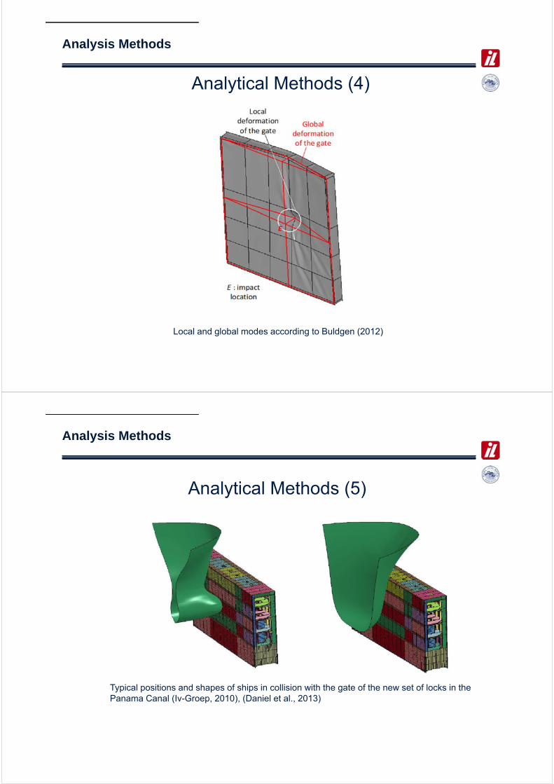
Analytical Methods (4)
Local and global modes according to Buldgen (2012)
Analysis Methods
Analytical Methods (5)
Typical positions and shapes of ships in collision with the gate of the new set of locks in the Panama Canal (Iv-Groep, 2010), (Daniel et al., 2013)

Analysis Methods
Analytical Methods (6)
Example of local gate deformation in ships collision analysis for the new set of locks in the Panama Canal (Iv-Groep, 2010), (Daniel et al., 2013)
Analysis Methods
Numerical Methods (1)
1. Quasi-static approaches
Finite element-based analyses of ship collision simulations have been performed in many commercial codes, such as LS-DYNA, ABAQUS, and MSC/DYTRAN. Commonly, the nonlinear material behaviour is selected in the form of a power law

Analysis Methods
Numerical Methods (2)
1. Dynamic approaches
In order to realistically assess the structural deformation, the distribution of energy between structural deformations and ship motions needs to be evaluated. Therefore, coupled dynamic collision simulations are the method of choice for a precise description of the entire collision process. Le Sourne et al. (2001) formulated the external dynamics of collisions in a three-dimensional space and included all the major external forces through a subroutine MCOL implemented into LS-DYNA. The coupling between the ship motions and the structural deformations was carried out simultaneously with the help of structural analysis with the finite element method.
Evaluation of Computation Methods
Methods Analysis effort ResultsModelling Computation Energy Loads Stress
Analytical methods
Least in volume, large in expertise
Least, special programs required, often unavailable
yes partially yes
Numerical methods -quasi-static approaches
Moderate in volume and expertise
Moderate, specialist programs required and available
partially partially yes
Numerical methods -dynamic approaches*
Extensive in volume and expertise
Time consuming and expensive. Extensive and dedicated software required
yes yes yes

Conclusion and recommendation
THANK YOU VERY MUCH FOR YOUR ATTENTION
Johnny Wong
Rogelio Gordon
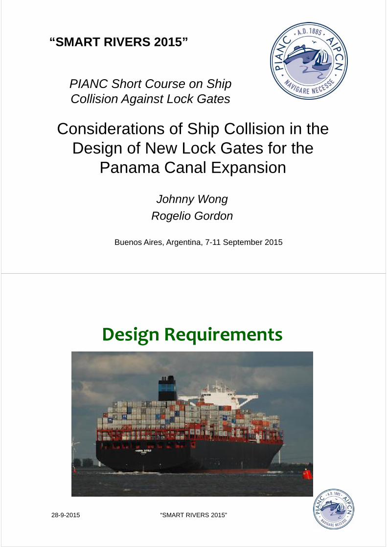
Considerations of Ship Collision in the Design of New Lock Gates for the
Panama Canal Expansion
Buenos Aires, Argentina, 7-11 September 2015
“SMART RIVERS 2015”
PIANC Short Course on Ship Collision Against Lock Gates
28-9-2015 “SMART RIVERS 2015”
Design Requirements

Gate collision requirements• New rolling gates must be able to resist the impact
of a 160,000 ton displacement ship travelling at a speed of 1 knot (0.514 m/s)
• After collision lock must be operable– Gate must be able to be retracted into slot
– Gate must hold water from upstream source
– Gate must keep its floation within limit
– Gate must keep in its track
• Note: Agreement with PIANC WG-151 report on designof lock gates for ship collision (published 2014)
PIANC Smart Rivers 2015
Design vessel• Neopanamax vessel 366 m LOA; 48.8 m beam;
15.2 m draft TFW; 13000 TEU containership
• Third set of locks 27 m lift in three consecutivechambers, dimensions: 458 m long, 55 m wide, 18.3 m to 27.5 m deep
PIANC Smart Rivers 2015

Vessel models• One containership modeled with bulbous bow,
blockage 0.65, displacement 222,000 tons
• One tanker/bulker modeled with vertical V-shapebow, blockage 0.48, displacement 224,000 tons
• Ships assisted with tugs modeled 34 m length, 12 m beam, 2.8 m draft, blockage 0.53
PIANC Smart Rivers 2015
Gate design• Each lock has four pairs of rolling gates 8-10 m
wide; 22-33 m tall; 57 m long; weight 2400-4200 ton
• Gate built with S355 and S460 grade steel
• Horizontal bearing pads on gate sides and bottomconstrain the horizontal movement and transmitloads to the concrete structure
• Gate built with 19 vertical block rows
• Buoyancy chambers set at bottom of gate
PIANC Smart Rivers 2015

28-9-2015 “SMART RIVERS 2015”
Model Setup
Ship direction and bow shape• Downlockage from lake to ocean of a ship with
bulbous bow– Water level at 27.13 m, draft of bulbous bow at 18.23 m,
so collision location will be 8.9 m below water line– During a downlockage a ship with bulbous bow will not
reach the buoyancy chambers from the upstream side
• Downlockage bulkcarrier with V-shaped bowcollision will be near top of gate
• Uplockage ship with bulbous bow will collide nearthe buoyancy chambers (V-shaped bow will notreach the buoyancy chambers)
PIANC Smart Rivers 2015

Ship eccentricity• Ship can impact gate at its center• Ship can also impact gate off-center with maximum
eccentricity of 4.5m • Since vertical frames are spaced at 3.2 m a ship can
collide a row or in-between rows, therefore only the midthree rows can be hit during collision– The analysis showed that the local skin damage is comparable
in both, the collision at a row, and with that of a collision betweenthe rows.
– A collision at a web gives a more direct global response, resulting in higher increase of load distribution to the horizontal bearings and is more severe for the vertical framing
PIANC Smart Rivers 2015
FE model
• Collision modeling by TNO Center for Mechanicaland Maritime Constructions, NL
• Using LSDYNA Finite Element based on ANSYS model used for the structural design and drawings
PIANC Smart Rivers 2015
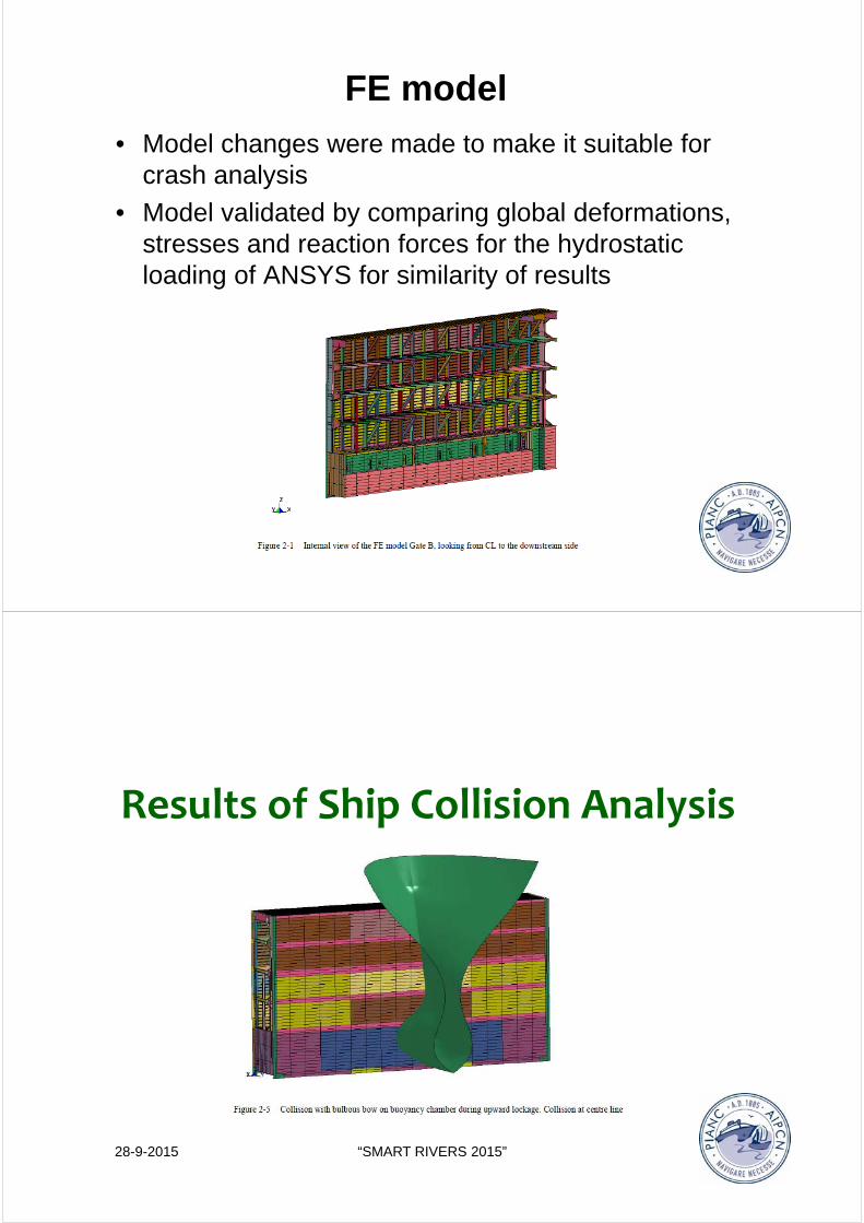
FE model
• Model changes were made to make it suitable forcrash analysis
• Model validated by comparing global deformations, stresses and reaction forces for the hydrostaticloading of ANSYS for similarity of results
PIANC Smart Rivers 2015
28-9-2015 “SMART RIVERS 2015”
Results of Ship Collision Analysis

Downlockage bulk carrier• After collision, the analysis showed that no
excessive failure is expected:– The required energy absorption is reached after
penetration of 1.06 m
PIANC Smart Rivers 2015
– No rupture of the shell plating willoccur and the structure behind theshell will only show local fracture
– The horizontal reaction force due tocollision is 63 MN, which is anincrease of 29% of the hydrostaticload forces
– The maximum global horizontal deflection of the gate is 0.145 m, anelastic deformation that will return toposition after the vessel has stopped
Downlockage bulbous bow
• The resulting analysis showed that after a collisionno excessive failure is expected for this scenario: – The required energy absorption by the gate is reached
after a penetrarion of 0.879 m
– The upstream shell plating remains intact and the structurebehind the shell shows very limited fracture
PIANC Smart Rivers 2015
– The horizontal reaction force dueto collision is estimated at 62 MN, which is 28% of the reaction forcesdue to hydrostatic loading.
– The global horizontal deflection of the gate is about 0.08 m, within itselastic range and will recuperateafter the ship has stopped

Uplockage bulbous bow• Analysis showed that this will not result in flooding of
its buoyancy chambers for this collision scenario:– Buoyancy chambers and shell plating will remain intact
– A small fracture may occur behind the shell plating in some webs
PIANC Smart Rivers 2015
– The required energy absorption isreached after a penetration of 0.76 m
– The maximum total horizontal reactionforce on the gate is 82 MN from thecollision
– The vertical reaction forces on the upperand lower wagon of the gate oscilatesbetween -2.77 MN and 3.26 MN, thus thewagon will remain in place
Other cases and results• The larger ships will be assisted with tugs ahead
and astern during lockage. The collision analysisincluded the case where a large ship pushed a harbor tug against the gate– This scenario is similar to the case where a ship with a
bulbous bow penetrates the gate. The bow of the tug is 5 m which will create a deeper penetration into the gate
– But it will cause less damage to the gate than the 8 m widebulbous bow of the containership which remains thegoverning case
PIANC Smart Rivers 2015

Conclusions• The analysis performed for the
different operating scenariosand ship types shows that theoverall structural integrity of thelock gate is not compromised bythe ship impact
• The damage will be limited tolocal plastic deformation with no rupture of critical structuralelements.
• In general, the gate remainselastic and it will be possible toretract the gate into its recess
PIANC Smart Rivers 2015
Conclusions• The analysis shows no puncture
of the buoyancy chambers and any possible loss of buoyancy willbe below the 25% allowed by thegate design
• The increase of horizontal loadingon the bearing surfaces of thegate resulting from the shipimpact does not impair the gatefunction
• All cases analyzed show verylimited temporary vertical uplift in the range of 1 to 2 millimeters off the gate from the supportwagons. The connection of thewagons to the gate allows forrelative large displacement, therefore the wagons will remainin place
PIANC Smart Rivers 2015

Panama Canal Third Set of LocksSet to Open on April 2016
PIANC Smart Rivers 2015

Presentation ofnewanalytical methods toassess thecrashworthiness oflock gates
PIANCSMARTRIVERSCONFERENCE
7– 11September 2015BuenosAires
LoïcBuldgen
University ofLiège(Belgium)
1.Introduction
2.Generalbackground
3.Required data
4.Analytical derivation
5.Numerical comparisons
6.Extensiontomitrelock gates
7.Conclusions
Presentation ofnewanalytical methods toassess thecrashworthiness oflock gates

1.Introduction
2.Generalbackground
3.Required data
4.Analytical derivation
5.Numerical comparisons
6.Extensiontomitrelock gates
7.Conclusions
1.1
Presentation ofnewanalytical methods toassess thecrashworthiness oflock gates
1.INTRODUCTION
1.1.Overview ofthewaterborne transportinEurope
1.2.Collisionanalysis oflock gates
1.3.Aim oftheanalytical methods
1.2

1.INTRODUCTION
1.1.Overview ofthewaterborne transportinEurope
1.2.Collisionanalysis oflock gates
1.3.Aim oftheanalytical methods
1.2
1.INTRODUCTION1.1.Overview ofthewaterborne transportinEurope
0
1000
2000
3000
4000
5000
6000
1995
1996
1997
1998
1999
2000
2001
2002
2003
2004
2005
2006
2007
2008
2009
2010
2011
2012
2013
2014
2015
Freighttransport(10
6tkm)
Year
©European Environment Agency
• Increasing freight transport since 1995
1.3

1.INTRODUCTION1.1.Overview ofthewaterborne transportinEurope
• Increasing freight transport since 1995
• Road transport is predominant
76%
18%
6%
Road Rail Inlandnavigation
©Eurostat
1.4‐1
1.INTRODUCTION1.1.Overview ofthewaterborne transportinEurope
©Eurostat
123
22,830,9
0
20
40
60
80
100
120
140
Roadtransport Railtransport Inlandnavigation
CO2em
issions(g/tkm
)
• Increasing freight transport since 1995
• Road transport is predominant⟶ high CO2 emissions
76%
18%
6%
Road Rail Inlandnavigation
1.4‐2

1.INTRODUCTION1.1.Overview ofthewaterborne transportinEurope
©Eurostat
Truckscongestion
• Increasing freight transport since 1995
• Road transport is predominant⟶ high CO2 emissions
• Limited road capacity
76%
18%
6%
Road Rail Inlandnavigation
1.4‐3
1.INTRODUCTION1.1.Overview ofthewaterborne transportinEurope
TruckscongestionWaterbornetransport
Shift
1barge≃200trucks
• Increasing freight transport since 1995
• Roadtransportis predominant⟶high CO2 emissions ⟹Newmodalsplit
• Limited road capacity
1.4‐4

1.INTRODUCTION1.1.Overview ofthewaterborne transportinEurope
• New modal split: increase waterbone transport
‐ CO2 emissions
‐ Air quality
‐ Noise nuisance
‐ Safety
‐ Land take
‐ Same infrastructure cost per tkm
1.5
1.INTRODUCTION1.1.Overview ofthewaterborne transportinEurope
• New modal split: increase waterbone transport
• European situation:
‐ Important sea ports
‐ Network: 40 000 km
‐ Currently under‐utilized
1.6‐1

1.INTRODUCTION1.1.Overview ofthewaterborne transportinEurope
• New modal split: increase waterbone transport
• European situation:
‐ Important sea ports
‐ Network: 40 000 km
‐ Currently under‐utilized
• European policy: NAIADES I and II
1.6‐2
1.INTRODUCTION1.1.Overview ofthewaterborne transportinEurope
• New modal split: increase waterbone transport
• European situation:
‐ Important sea ports
‐ Network: 40 000 km
‐ Currently under‐utilized
• European policy: NAIADES I and II
DesignnewlocksImprove existing ones
1.6‐3

1.INTRODUCTION
1.1.Overview ofthewaterborne transportinEurope
1.2.Collisionanalysis oflock gates
1.3.Aim oftheanalytical methods
1.7
1.INTRODUCTION1.2.Collisionanalysis oflock gates
DesignnewlocksImprove existing ones
• Need to account for accidental actions
1.8‐1

1.INTRODUCTION1.2.Collisionanalysis oflock gates
DesignnewlocksImprove theexisting ones
• Need to account for accidental actions
‐ Keep the structure undamaged
1.8‐2
1.INTRODUCTION1.2.Collisionanalysis oflock gates
DesignnewlocksImprove theexisting ones
• Need to account for accidental actions
‐ Keep the structure undamaged
‐ Proportionate consequences
1.8‐3

1.INTRODUCTION1.2.Collisionanalysis oflock gates
DesignnewlocksImprove theexisting ones
• Need to account for accidental actions
• Crucial point: pre‐design
1.8‐4
1.INTRODUCTION1.2.Collisionanalysis oflock gates
DesignnewlocksImprove theexisting ones
• Need to account for accidental actions
• Crucial point: pre‐design
• Ship impact is a key issue
‐ Little information in international standard
‐ Little information in the literature
1.8‐5

1.INTRODUCTION1.2.Collisionanalysis oflock gates
DesignnewlocksImprove theexisting ones
Howtointegrate ship impact inthepre‐designoflocks ?
• Need to account for accidental actions
• Crucial point: pre‐design
• Ship impact is a key issue
1.8‐6
1.INTRODUCTION1.2.Collisionanalysis oflock gates
Howtointegrate ship impact inthepre‐designoflocks ?
• Perform finite element analyses
1.9‐1

1.INTRODUCTION1.2.Collisionanalysis oflock gates
Howtointegrate ship impactinthepre‐designoflocks ?
• Perform finite element analyses
‐ Detailed results
‐ Realistic model
1.9‐2
1.INTRODUCTION1.2.Collisionanalysis oflock gates
Howtointegrate ship impactinthepre‐designoflocks ?
• Perform finite element analyses
‐ Build the models (Gate and vessel)
‐ Critical scenarios (Impact point)
‐ Run simulations (Dynamic non‐linear)
‐ Post‐processing (Voluminous)
1.9‐3
1.INTRODUCTION1.2.Collisionanalysis oflock gates
Howtointegrate ship impactinthepre‐designoflocks ?
• Perform finite element analyses
• Time demanding
1.9‐4
1.INTRODUCTION1.2.Collisionanalysis oflock gates
Howtointegrate ship impactinthepre‐designoflocks ?
1.9‐5
• Perform finite element analyses
• Time demanding
• Licenses
1.INTRODUCTION1.2.Collisionanalysis oflock gates
Howtointegrate ship impactinthepre‐designoflocks ?
1.9‐6
Expansive…
• Perform finite element analyses
• Time demanding
• Licenses
1.INTRODUCTION1.2.Collisionanalysis oflock gates
Howtointegrate ship impactinthepre‐designoflocks ?
1.9‐7
• Perform finite element analyses
• Time demanding
• Licenses
…orillegal
1.INTRODUCTION1.2.Collisionanalysis oflock gates
Howtointegrate ship impactinthepre‐designoflocks ?
• Perform finite element analyses
• Time demanding
• Licenses
• Not suited for optimization (Iterations)
1.9‐8
1.INTRODUCTION1.2.Collisionanalysis oflock gates
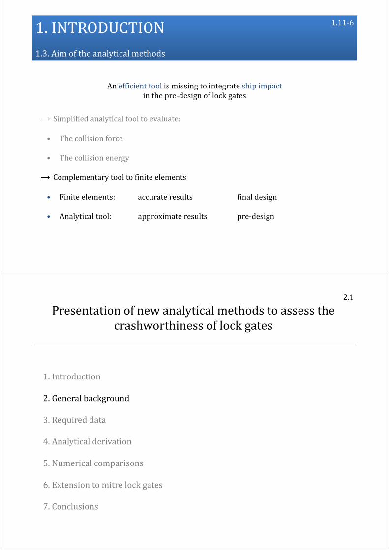
Howtointegrate ship impact inthepre‐designoflocks ?
Anefficienttool is missing
• Perform finite element analyses
• Time demanding
• Licenses
• Not suited for optimization
1.9‐9

1.INTRODUCTION
1.1.Overview ofthewaterborne transportinEurope
1.2.Collisionanalysis oflock gates
1.3.Aim oftheanalytical methods
1.10
1.INTRODUCTION1.3.Aim oftheanalytical methods
Anefficienttool is missing tointegrate ship impactinthepre‐designoflock gates
1.11‐1

1.INTRODUCTION1.3.Aim oftheanalytical methods
Anefficienttool is missing tointegrate ship impactinthepre‐designoflock gates
⟶ Simplified analytical tool to evaluate:
1.11‐2
1.INTRODUCTION1.3.Aim oftheanalytical methods
Anefficienttool is missing tointegrate ship impactinthepre‐designoflock gates
⟶ Simplified analytical tool to evaluate:
• The collision force
1.11‐3

1.INTRODUCTION1.3.Aim oftheanalytical methods
Anefficienttool is missing tointegrate ship impactinthepre‐designoflock gates
⟶ Simplified analytical tool to evaluate:
• The collision force
• The collision energy
1.11‐4
1.INTRODUCTION1.3.Aim oftheanalytical methods
Anefficienttool is missing tointegrate ship impactinthepre‐designoflock gates
⟶ Simplified analytical tool to evaluate:
• The collision force
• The collision energy
⟶ Complementary tool to finite elements
1.11‐5
1.INTRODUCTION1.3.Aim oftheanalytical methods
Anefficienttool is missing tointegrate ship impactinthepre‐designoflock gates
⟶ Simplified analytical tool to evaluate:
• The collision force
• The collision energy
⟶ Complementary tool to finite elements
• Finite elements: accurate results final design
• Analytical tool: approximate results pre‐design
1.11‐6
1.Introduction
2.Generalbackground
3.Required data
4.Analytical derivation
5.Numerical comparisons
6.Extensiontomitrelock gates
7.Conclusions
2.1
Presentation ofnewanalytical methods toassess thecrashworthiness oflock gates

2.GENERALBACKGROUND
2.1. Procedure toderive analytical solutions
2.2. Theupper‐bound method
2.3. Theequilibriummethod
2.4. Summary
2.2
2.GENERALBACKGROUND
2.1. Procedure toderive analytical solutions
2.2. Theupper‐bound method
2.3. Theequilibriummethod
2.4. Summary
2.2

2.GENERALBACKGROUND2.1.Procedure toderive analytical solutions
• Experimental methods
‐ Individual component
‐ Technical challenge
‐ Financial challenge
2.3‐1
2.GENERALBACKGROUND2.1.Procedure toderive analytical solutions
• Experimental methods
‐ Individual component
‐ Technical challenge
‐ Financial challenge
• Finite element methods
‐ Complex model
‐ Refined analyses
2.3‐2

2.GENERALBACKGROUND2.1.Procedure toderive analytical solutions
• Experimental methods
‐ Individual component
‐ Technical challenge
‐ Financial challenge
• Finite element methods
‐ Complex model
‐ Refined analyses
• Analytical methods
‐ Simplified model
‐ Global results
2.3‐3
2.GENERALBACKGROUND2.1.Procedure toderive analytical solutions
‐ Individual component
‐ Technical challenge
‐ Financial challenge
‐ Complex model
‐ Refined analyses
• Analytical methods
• Experimental methods
• Finite element methods
Validation
‐ Simplified model
‐ Global results
2.3‐4

2.GENERALBACKGROUND2.1.Procedure toderive analytical solutions
‐ Individual component
‐ Technical challenge
‐ Financial challenge
‐ Complex model
‐ Refined analyses
• Analytical methods
• Experimental methods
• Finite element methods
Validation
‐ Simplified model
‐ Global results
2.3‐5
2.GENERALBACKGROUND2.1.Procedure toderive analytical solutions
• Derive closed‐form solutions for the impact force
2.4‐1

2.GENERALBACKGROUND2.1.Procedure toderive analytical solutions
• Derive closed‐form solutions for the impact force
• Rigorous theoretical basis for analytical methods
‐ Finite displacements
‐ Plasticity
2.4‐2
2.GENERALBACKGROUND2.1.Procedure toderive analytical solutions
• Derive closed‐form solutions for the impact force
• Rigorous theoretical basis for analytical methods
‐ Finite displacements
‐ Plasticity
⟶ No simplified formulation
2.4‐3

2.GENERALBACKGROUND2.1.Procedure toderive analytical solutions
• Derive closed‐form solutions for the impact force
• Rigorous theoretical basis for analytical methods
‐ Finite displacements
‐ Plasticity
⟶ No simplified formulation
• Approximate theories
‐ Upper‐bound method
‐ Equilibrium method
2.4‐4
2.GENERALBACKGROUND
2.1. Procedure toderive analytical solutions
2.2. Theupper‐bound method
2.3. Theequilibriummethod
2.4. Summary
2.5

2.GENERALBACKGROUND2.2.Theupper‐bound method
• Particularly suited for shells but also applicable to beams
2.6‐1
2.GENERALBACKGROUND2.2.Theupper‐bound method
• Particularly suited for shells but also applicable to beams
• Energy balance:
2.6‐2

2.GENERALBACKGROUND2.2.Theupper‐bound method
External powerofthecrushing force
2.6‐3
• Particularly suited for shells but also applicable to beams
• Energy balance:
2.GENERALBACKGROUND2.2.Theupper‐bound method
Internal energyrate
2.6‐4
External powerofthecrushing force
• Particularly suited for shells but also applicable to beams
• Energy balance:

2.GENERALBACKGROUND2.2.Theupper‐bound method
2.6‐5
• Particularly suited for shells but also applicable to beams
• Energy balance
• Small displacements
2.GENERALBACKGROUND2.2.Theupper‐bound method
2.6‐6
• Particularly suited for shells but also applicable to beams
• Energy balance
• Small displacements but extended to moderate ones:

2.GENERALBACKGROUND2.2.Theupper‐bound method
Green‐Lagrangeplastic:strain rate
2.6‐7
• Particularly suited for shells but also applicable to beams
• Energy balance
• Small displacements but extended to moderate ones:
2.GENERALBACKGROUND2.2.Theupper‐bound method
2.6‐8
Green‐Lagrangetensor:
• Particularly suited for shells but also applicable to beams
• Energy balance
• Small displacements but extended to moderate ones:

2.GENERALBACKGROUND2.2.Theupper‐bound method
2.6‐9
Green‐Lagrangetensor:
• Particularly suited for shells but also applicable to beams
• Energy balance
• Small displacements but extended to moderate ones:
2.GENERALBACKGROUND2.2.Theupper‐bound method
2.6‐10
⟶InitialaxesX1,X2,X3
Green‐Lagrangetensor:
• Particularly suited for shells but also applicable to beams
• Energy balance
• Small displacements but extended to moderate ones:

2.GENERALBACKGROUND2.2.Theupper‐bound method
2.6‐11
⟶Undeformedconfiguration
⟶InitialaxesX1,X2,X3
Green‐Lagrangetensor:
• Particularly suited for shells but also applicable to beams
• Energy balance
• Small displacements but extended to moderate ones:
2.GENERALBACKGROUND2.2.Theupper‐bound method
2.6‐12
Plasticflowstress
Green‐Lagrangeplastic:strain rate
• Particularly suited for shells but also applicable to beams
• Energy balance
• Small displacements but extended to moderate ones:
Green‐Lagrangeplastic:strain rate

2.GENERALBACKGROUND2.2.Theupper‐bound method
2.6‐13
• Particularly suited for shells but also applicable to beams
• Energy balance
• Small displacements but extended to moderate ones
Example:impactonaplasticbeam
2.GENERALBACKGROUND2.2.Theupper‐bound method
2.7‐1
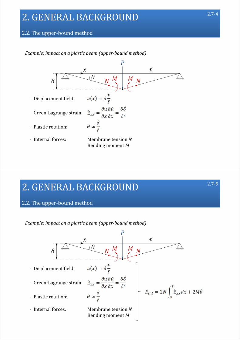
Example: impact on a plastic beam (upper‐bound method)
‐ Displacement field:

2.GENERALBACKGROUND2.2.Theupper‐bound method
2.7‐2
Example: impact on a plastic beam (upper‐bound method)
‐ Displacement field:
‐ Green‐Lagrange strain:
2.GENERALBACKGROUND2.2.Theupper‐bound method
2.7‐3
Example: impact on a plastic beam (upper‐bound method)
‐ Displacement field:
‐ Green‐Lagrange strain:
‐ Plastic rotation:
2.GENERALBACKGROUND2.2.Theupper‐bound method
2.7‐4
Example: impact on a plastic beam (upper‐bound method)
‐ Displacement field:
‐ Green‐Lagrange strain:
‐ Plastic rotation:
‐ Internal forces: Membrane tension NBending momentM
2.GENERALBACKGROUND2.2.Theupper‐bound method
2.7‐5
Example: impact on a plastic beam (upper‐bound method)
‐ Displacement field:
‐ Green‐Lagrange strain:
‐ Plastic rotation:
‐ Internal forces: Membrane tension NBending momentM

2.GENERALBACKGROUND2.2.Theupper‐bound method
2.7‐6
Example: impact on a plastic beam (upper‐bound method)
‐ Displacement field:
‐ Green‐Lagrange strain:
‐ Plastic rotation:
‐ Internal forces: Membrane tension NBending momentM
2.GENERALBACKGROUND2.2.Theupper‐bound method
2.7‐7
Example: impact on a plastic beam (upper‐bound method)
‐ Internal power:
2.GENERALBACKGROUND2.2.Theupper‐bound method
2.7‐8
Example: impact on a plastic beam (upper‐bound method)
‐ Internal power:
‐ External power:
2.GENERALBACKGROUND2.2.Theupper‐bound method
2.7‐9
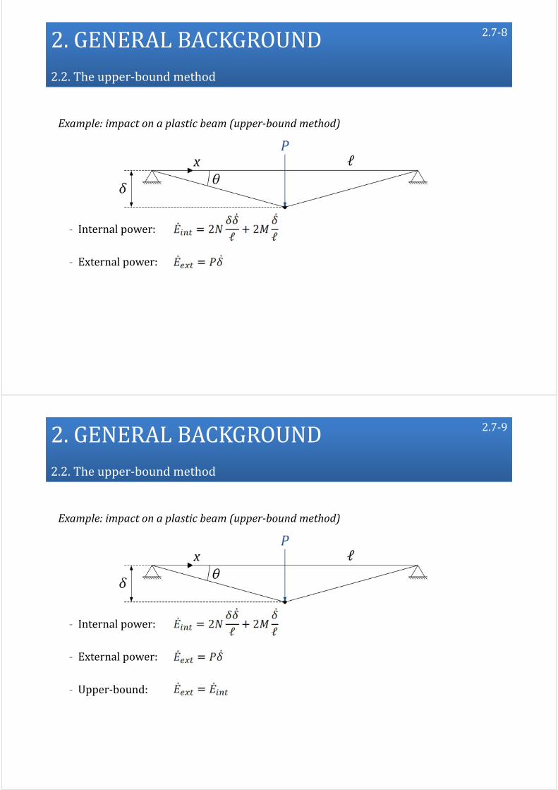
Example: impact on a plastic beam (upper‐bound method)
‐ Internal power:
‐ External power:
‐ Upper‐bound:

2.GENERALBACKGROUND2.2.Theupper‐bound method
2.7‐10
Example: impact on a plastic beam (upper‐bound method)
‐ Internal power:
‐ External power:
‐ Upper‐bound:
2.GENERALBACKGROUND2.2.Theupper‐bound method
2.7‐11
Example: impact on a plastic beam (upper‐bound method)
‐ Internal power:
‐ External power:
‐ Upper‐bound:

2.GENERALBACKGROUND2.2.Theupper‐bound method
2.7‐12
Example: impact on a plastic beam (upper‐bound method)
‐ Internal power:
‐ External power:
‐ Upper‐bound:
Smalldisplacements
2.GENERALBACKGROUND2.2.Theupper‐bound method
2.7‐13
Example: impact on a plastic beam (upper‐bound method)
‐ Internal power:
‐ External power:
‐ Upper‐bound:
SmalldisplacementsLarge
displacements

2.GENERALBACKGROUND
2.1. Procedure toderive analytical solutions
2.2. Theupper‐bound method
2.3. Theequilibriummethod
2.4. Summary
2.8
2.GENERALBACKGROUND2.3.Theequilibriummethod
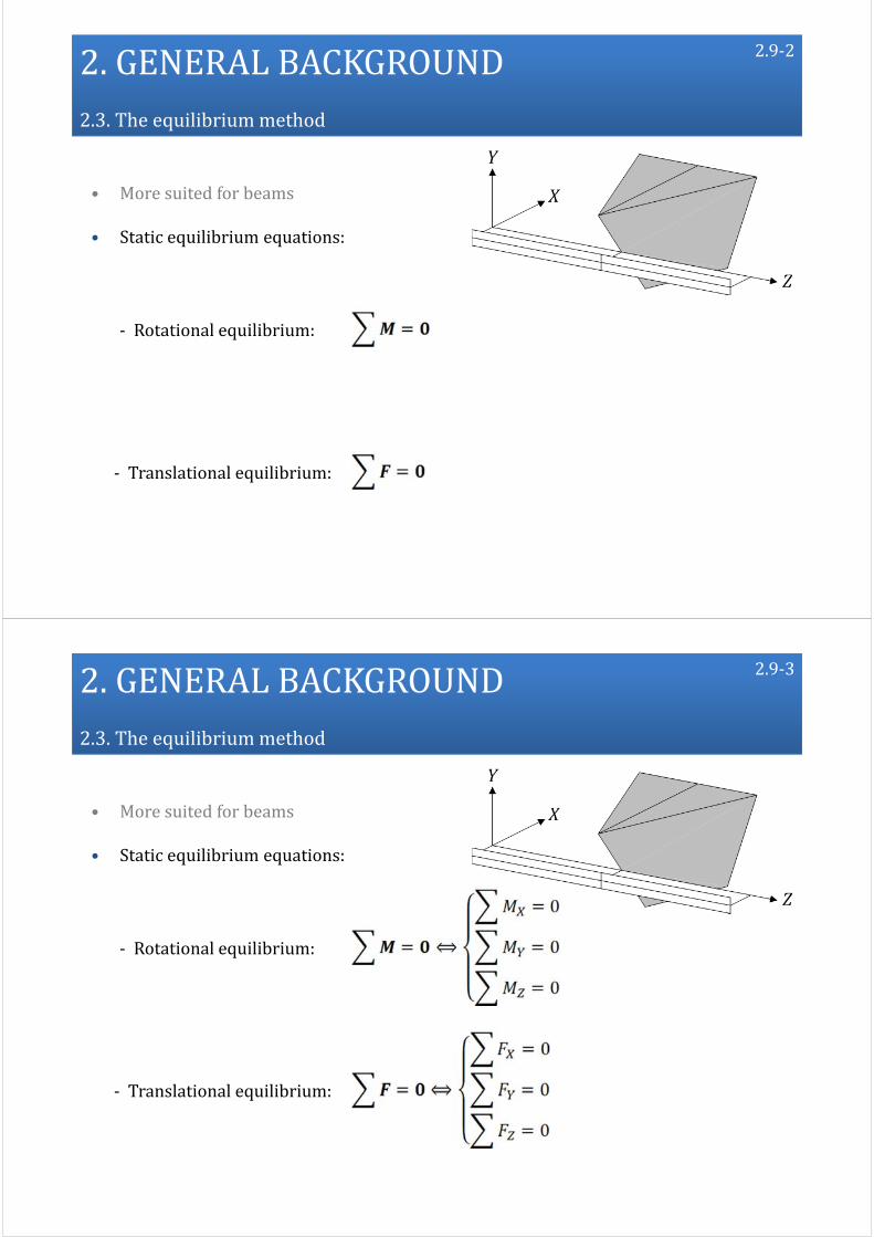
• More suited for beams
2.9‐1
2.GENERALBACKGROUND2.3.Theequilibriummethod
• More suited for beams
• Static equilibrium equations:
2.9‐2
‐ Rotational equilibrium:
‐ Translational equilibrium:
2.GENERALBACKGROUND2.3.Theequilibriummethod
• More suited for beams
• Static equilibrium equations:
2.9‐3
‐ Rotational equilibrium:
‐ Translational equilibrium:

2.GENERALBACKGROUND2.3.Theequilibriummethod
• More suited for beams
• Static equilibrium equations:
2.9‐4
‐ Rotational equilibrium:
‐ Translational equilibrium:
Only intheimpactplane
2.GENERALBACKGROUND2.3.Theequilibriummethod
2.9‐5
• More suited for beams
• Static equilibrium equations
• Deformed configuration to account for moderate displacements

2.GENERALBACKGROUND2.3.Theequilibriummethod
2.9‐6
• More suited for beams
• Static equilibrium equations
• Deformed configuration to account for moderate displacements
Example:impactonaplasticbeam
2.GENERALBACKGROUND2.3.Theequilibriummethod
2.10‐1
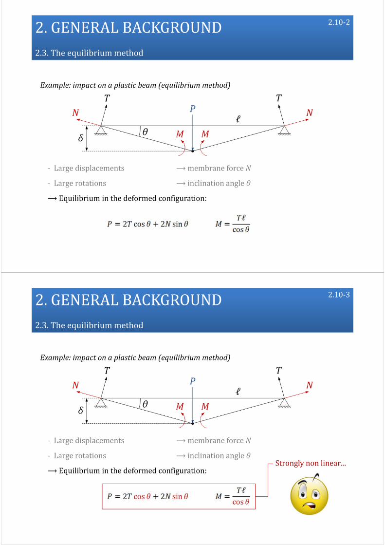
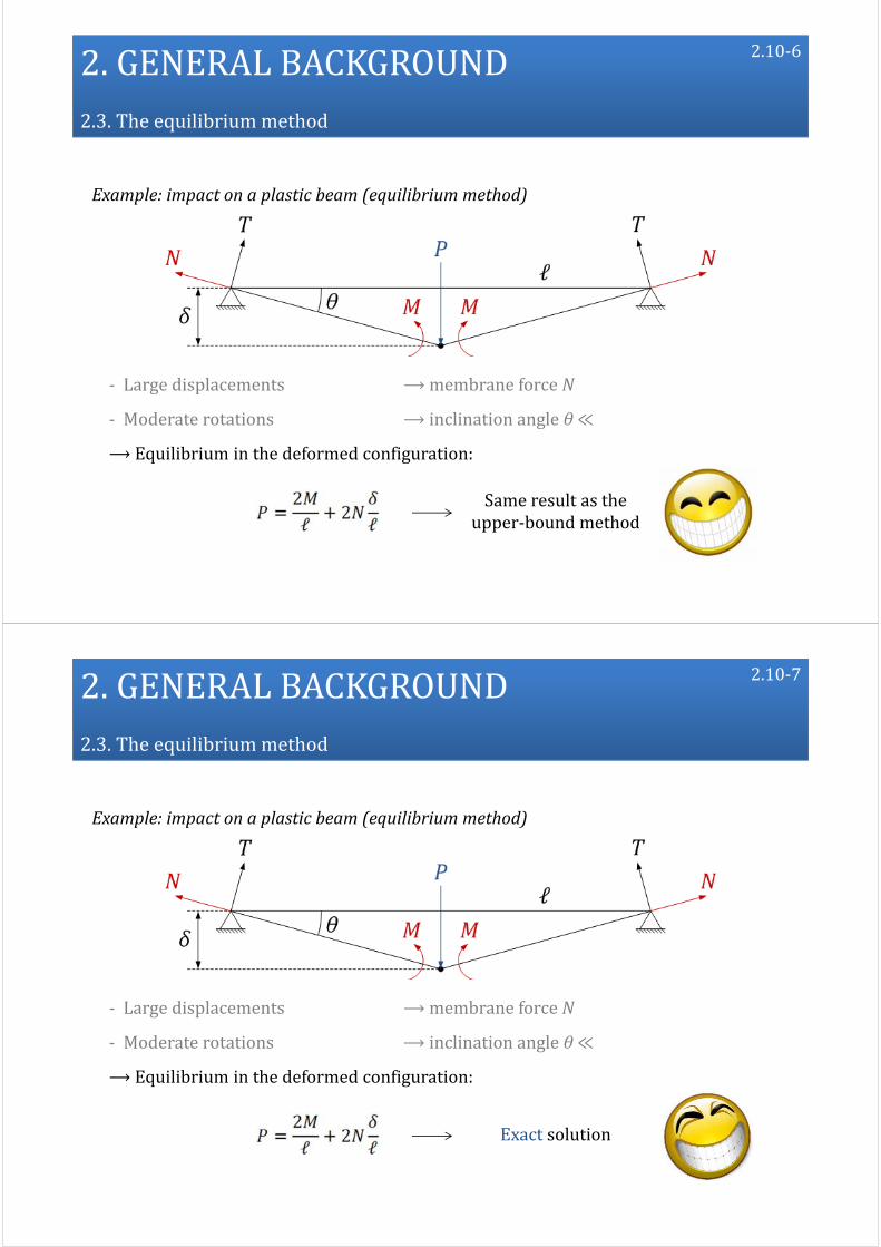
Example: impact on a plastic beam (equilibrium method)
‐ Large displacements ⟶membrane force N
‐ Large rotations ⟶ inclination angle θ
2.GENERALBACKGROUND2.3.Theequilibriummethod
2.10‐2
‐ Large displacements ⟶membrane force N
‐ Large rotations ⟶ inclination angle θ
⟶Equilibrium in the deformed configuration:
Example: impact on a plastic beam (equilibrium method)
2.GENERALBACKGROUND2.3.Theequilibriummethod
2.10‐3
‐ Large displacements ⟶membrane force N
‐ Large rotations ⟶ inclination angle θ
⟶Equilibrium in the deformed configuration:Strongly nonlinear…
Example: impact on a plastic beam (equilibrium method)

2.GENERALBACKGROUND2.3.Theequilibriummethod
2.10‐4
‐ Large displacements ⟶membrane force N
‐ Moderate rotations ⟶ inclination angle θ≪Strongly nonlinear…
⟶ Equilibrium in the deformed configuration:
Example: impact on a plastic beam (equilibrium method)
2.GENERALBACKGROUND2.3.Theequilibriummethod
2.10‐5
‐ Large displacements ⟶membrane force N
‐ Moderate rotations ⟶ inclination angle θ≪
⟶Equilibrium in the deformed configuration:Analytically tractable
Example: impact on a plastic beam (equilibrium method)
2.GENERALBACKGROUND2.3.Theequilibriummethod
2.10‐6
‐ Large displacements ⟶membrane force N
‐ Moderate rotations ⟶ inclination angle θ≪
⟶Equilibrium in the deformed configuration:
Same result astheupper‐bound method
Example: impact on a plastic beam (equilibrium method)
2.GENERALBACKGROUND2.3.Theequilibriummethod
2.10‐7
‐ Large displacements ⟶membrane force N
‐ Moderate rotations ⟶ inclination angle θ≪
⟶Equilibrium in the deformed configuration:
Exact solution
Example: impact on a plastic beam (equilibrium method)

2.GENERALBACKGROUND
2.1. Procedure toderive analytical solutions
2.2. Theupper‐bound method
2.3. Theequilibriummethod
2.4. Summary
2.11
2.GENERALBACKGROUND2.4.Summary
2.12‐1
• The upper‐bound method
‐ Particularly suited for shells but also applicable to beams
‐ Based on an energy balance
‐ Valid for small displacements but extended to moderate ones

2.GENERALBACKGROUND2.4.Summary
2.12‐2
• The upper‐bound method
‐ Particularly suited for shells but also applicable to beams
‐ Based on an energy balance
‐ Valid for small displacements but extended to moderate ones
• The equilibrium method
‐ More suited for beams
‐ Based on static equilibrium equations
‐ Deformed configuraiton to account for moderate displacements
2.GENERALBACKGROUND2.4.Summary
• The upper‐bound method
• The equilibrium method
2.12‐3
Equivalentforsmall displacements
(principle ofvirtual velocities)

2.GENERALBACKGROUND2.1.Generalbackground
• The upper‐bound method
• The equilibrium method
Validity of these methods ?
‐ Literature
‐ Experimental validations
‐ Numerical validations
2.12‐4
Equivalentforsmall displacements
(principle ofvirtual velocities)
1.Introduction
2.Generalbackground
3.Required data
4.Analytical derivation
5.Numerical comparisons
6.Extensiontomitrelock gates
7.Conclusions
3.1
Presentation ofnewanalytical methods toassess thecrashworthiness oflock gates

3.REQUIREDDATA
3.1. Definition ofthegate
3.2. Definition ofthevessel
3.3. Definition oftheimpactscenario
3.2
3.REQUIREDDATA
3.1. Definition ofthegate
3.2. Definition ofthevessel
3.3. Definition oftheimpactscenario
3.2

3.REQUIREDDATA3.1.Definition ofthegate
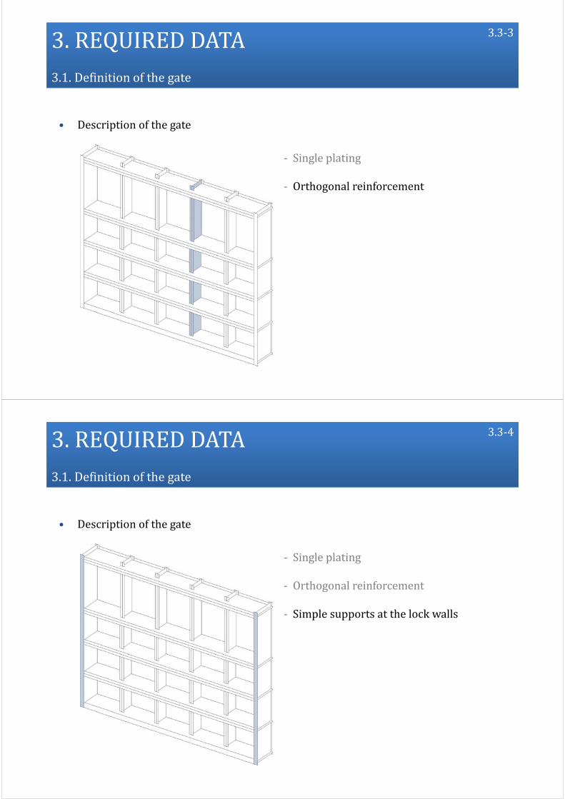
• Description of the gate
‐ Single plating
3.3‐1
3.REQUIREDDATA3.1.Definition ofthegate
• Description of the gate
‐ Single plating
‐ Orthogonal reinforcement
3.3‐2
3.REQUIREDDATA3.1.Definition ofthegate
• Description of the gate
‐ Single plating
‐ Orthogonal reinforcement
3.3‐3
3.REQUIREDDATA3.1.Definition ofthegate
• Description of the gate
‐ Single plating
‐ Orthogonal reinforcement
‐ Simple supports at the lock walls
3.3‐4

3.REQUIREDDATA3.1.Definition ofthegate
• Description of the gate
‐ Single plating
‐ Orthogonal reinforcement
‐ Simple supports at the lock walls
‐ Free sliding at the lock walls
3.3‐5
3.REQUIREDDATA3.1.Definition ofthegate
• Description of the gate
‐ Single plating
‐ Orthogonal reinforcement
‐ Simple supports at the lock walls
‐ Free sliding at the lock walls
‐ Eventually: simple supports at the bottom
3.3‐6

3.REQUIREDDATA3.1.Definition ofthegate
• Required data for the gate
N° Y hw tw hf tf
Girders 1 … … … … …
2 … … … … …
⋮
Fram
es
1 … … … … …
2 … … … … …
⋮Stiffeners 1 … … … … …
2 … … … … …
⋮
Plating thickness tp …
‐ Geometrical properties
3.4‐1
3.REQUIREDDATA3.1.Definition ofthegate
• Required data for the gate
3.4‐2
‐ Geometrical properties
‐ Material properties
YoungModulus E …
Yield stress σ0 …

3.REQUIREDDATA
3.1. Definition ofthegate
3.2. Definition ofthevessel
3.3. Definition oftheimpactscenario
3.5
3.REQUIREDDATA3.2.Definition ofthevessel
• Description of the vessel
3.6
Raked bow Bulbous bow

3.REQUIREDDATA3.2.Definition ofthevessel
• Description of the vessel
‐ Idealized bow shape
3.7‐1
3.REQUIREDDATA3.2.Definition ofthevessel
• Description of the vessel
‐ Idealized bow shape
‐ Parabolic stem
3.7‐2

3.REQUIREDDATA3.2.Definition ofthevessel
• Description of the vessel
‐ Idealized bow shape
‐ Parabolic stem
3.7‐3
3.REQUIREDDATA3.2.Definition ofthevessel
• Description of the vessel
‐ Idealized bow shape
‐ Parabolic stem
‐ Elliptic bulb
3.7‐4

3.REQUIREDDATA3.2.Definition ofthevessel
• Description of the vessel
‐ Idealized bow shape
‐ Parabolic stem
‐ Elliptic bulb
3.7‐5
3.REQUIREDDATA3.2.Definition ofthevessel
• Required data for the vessel
3.8‐1
‐ Geometrical properties
Stem
X radiusofthestem q …
Z radiusofthestem p …
Height ofthestem hb …
Stemangle ϕ …
Side angle ψ …
Bulb
X radiusofthebulb RX …
Y radius ofthebulb RY …
Z radiusofthebulb RZ …

3.REQUIREDDATA3.2.Definition ofthevessel
• Required data for the vessel
3.8‐2
‐ Material properties⟶ useless: perfectly rigid vessel
‐ Geometrical properties
3.REQUIREDDATA
3.1. Definition ofthegate
3.2. Definition ofthevessel
3.3. Definition oftheimpactscenario
3.9
3.REQUIREDDATA3.3.Definition oftheimpactscenario
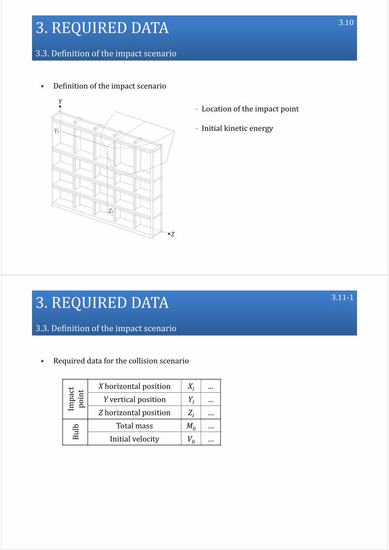
• Definition of the impact scenario
‐ Location of the impact point
‐ Initial kinetic energy
3.10
3.REQUIREDDATA3.3.Definition oftheimpactscenario
• Required data for the collision scenario
3.11‐1
Impact
point X horizontalposition XI …
Yverticalposition YI …
Z horizontal position ZI …
Bulb Totalmass M0 …
Initial velocity V0 …

3.REQUIREDDATA3.3.Definition oftheimpactscenario
• Required data for the collision scenario
3.11‐2
Impact
point X horizontalposition XI …
Yverticalposition YI …
Z horizontal position ZI …
Bulb Totalmass M0 …
Initial velocity V0 …
⟶ Very few parameters to introduce
3.REQUIREDDATA3.3.Definition oftheimpactscenario
3.11‐3
⟶ Very few parameters to introduce ≠ Pre‐processing with finiteelement software
Impact
point X horizontalposition XI …
Yverticalposition YI …
Z horizontal position ZI …
Bulb Totalmass M0 …
Initial velocity V0 …
• Required data for the collision scenario

1.Introduction
2.Generalbackground
3.Required data
4.Analytical derivation
5.Numerical comparisons
6.Extensiontomitrelock gates
7.Conclusions
4.1
Presentation ofnewanalytical methods toassess thecrashworthiness oflock gates
4.Analytical derivation
4.1. Deformation sequence
4.2. Totalresistance
4.3. Localresistance
4.4. Globalresistance
4.5. Summary
4.2
4.Analytical derivation
4.1. Deformation sequence
4.2. Totalresistance
4.3. Localresistance
4.4. Globalresistance
4.5. Summary
4.2
4.Analytical derivation4.1.Deformation sequence
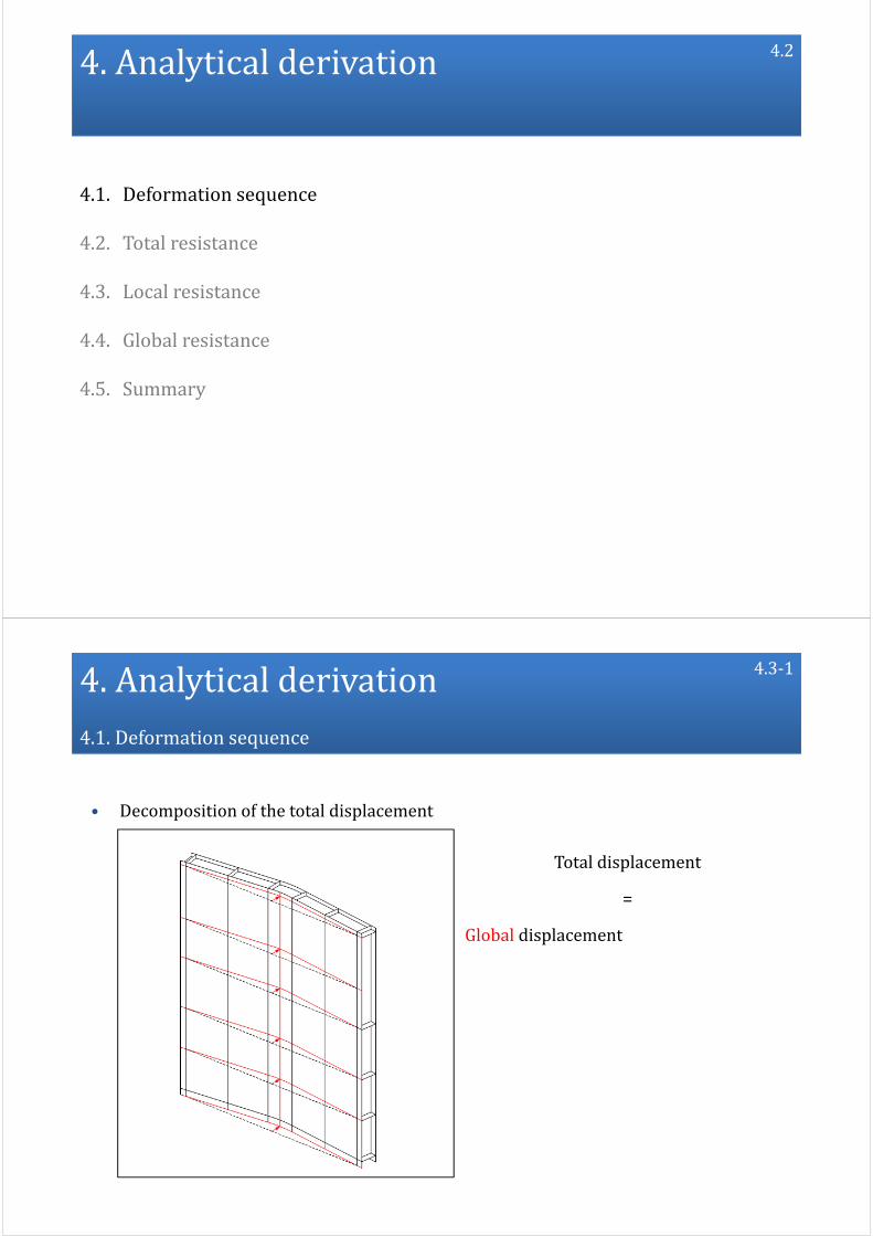
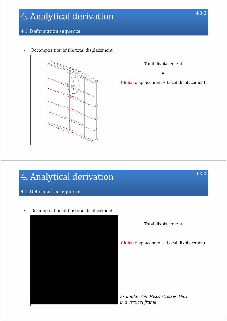
• Decomposition of the total displacement
Totaldisplacement
=
Global displacement +Localdisplacement
4.3‐1
4.Analytical derivation4.1.Deformation sequence
• Decomposition of the total displacement
Totaldisplacement
=
Global displacement +Local displacement
4.3‐2
4.Analytical derivation4.1.Deformation sequence
• Decomposition of the total displacement
Totaldisplacement
=
Global displacement +Local displacement
Example: Von Mises stresses (Pa)in a vertical frame
4.3‐3

4.Analytical derivation4.1.Deformation sequence
• Decomposition of the total displacement
Totaldisplacement
=
Global displacement +Localdisplacement
4.3‐4
Example: Von Mises stresses (Pa)in a vertical frame
4.Analytical derivation4.1.Deformation sequence
• Decomposition of the total displacement
Totaldisplacement
=
Global displacement +Local displacement
4.3‐5
Example: Von Mises stresses (Pa)in a vertical frame

4.Analytical derivation4.1.Deformation sequence
• Decomposition of the total displacement (δ < δt)
Hypothesis:
Phase1: δ <δt⟶Local displacement
4.4‐1
Example: Von Mises stresses (Pa)in a vertical frame
4.Analytical derivation4.1.Deformation sequence
• Decomposition of the total displacement (δ < δt)
Hypothesis:
Phase1: δ <δt⟶Local displacement
4.4‐2
Example: Von Mises stresses (Pa)in a vertical frame

4.Analytical derivation4.1.Deformation sequence
• Decomposition of the total displacement (δ < δt)
Hypothesis:
Phase1: δ <δt⟶Local displacement
4.4‐3
Example: Von Mises stresses (Pa)in a vertical frame
4.Analytical derivation4.1.Deformation sequence
• Decomposition of the total displacement (δ > δt)
Hypothesis:
Phase1: δ <δt⟶Localdisplacement
Phase2: δ >δt⟶Global displacement
4.4‐4
Example: Von Mises stresses (Pa)in a vertical frame

4.Analytical derivation4.1.Deformation sequence
• Decomposition of the total displacement (δ > δt)
Hypothesis:
Phase1: δ <δt⟶Localdisplacement
Phase2: δ >δt⟶Globaldisplacement
⟶Two successivemotions
4.4‐5
Example: Von Mises stresses (Pa)in a vertical frame
4.Analytical derivation4.1.Deformation sequence
• Decomposition of the total displacement (δ > δt)
Hypothesis:
Phase1: δ <δt⟶Localdisplacement
Phase2: δ >δt⟶Globaldisplacement
⟶Two successivemotions
⟶Two decoupled motions
4.4‐6
Example: Von Mises stresses (Pa)in a vertical frame

4.Analytical derivation
4.1. Deformation sequence
4.2. Totalresistance
4.3. Localresistance
4.4. Globalresistance
4.5. Summary
4.7
4.Analytical derivation4.2.Totalresistance
• Resistance
4.8‐1
‐ δ < δt : Phase 1
PL Local resistance due to localized crushing

4.Analytical derivation4.2.Totalresistance
• Resistance
‐ δ < δt : Phase 1
PL Local resistance due to localized crushing
Pt Force to activate a global plastic mechanism
4.8‐2
4.Analytical derivation4.2.Totalresistance
• Resistance
4.8‐3
‐ δ < δt : Phase 1
PL Local resistance due to localized crushing
Pt Force to activate a global plastic mechanism
‐ δ = δt : Transition when PL = Pt

4.Analytical derivation4.2.Totalresistance
• Resistance
4.8‐4
‐ δ < δt : Phase 1
PL Local resistance due to localized crushing
Pt Force to activate a global plastic mechanism
‐ δ = δt : Transition when PL = Pt
‐ δ > δt : Phase 2
PG Global resistance due to overall bending
4.Analytical derivation4.2.Totalresistance
• Resistance
‐ Total resistance P :
If δ < δt : P = PL
If δ > δt : P = PG
4.8‐5
4.Analytical derivation4.2.Totalresistance
• Resistance
Not realistic: local and global coupling if δ < δt
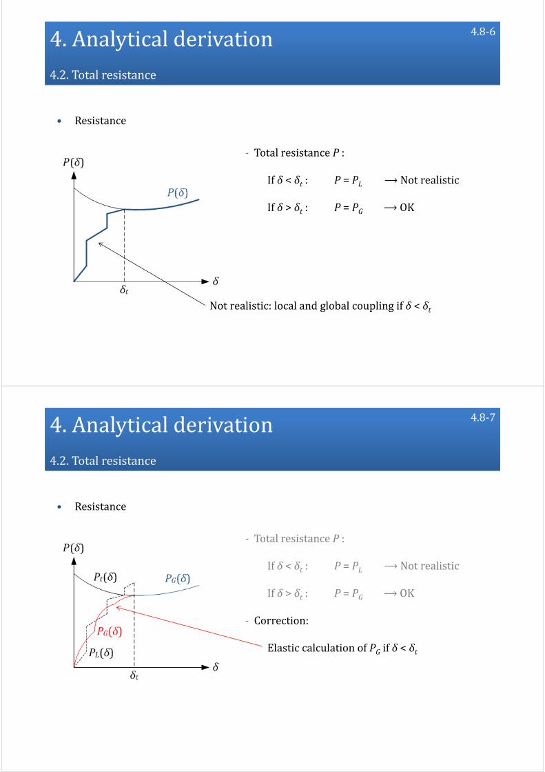
‐ Total resistance P :
If δ < δt : P = PL ⟶Not realistic
If δ > δt : P = PG ⟶OK
4.8‐6
4.Analytical derivation4.2.Totalresistance
• Resistance
‐ Total resistance P :
If δ < δt : P = PL ⟶Not realistic
If δ > δt : P = PG ⟶OK
‐ Correction:
Elastic calculation of PG if δ < δt
4.8‐7

4.Analytical derivation4.2.Totalresistance
• Resistance
‐ Total resistance P :
If δ < δt : P = PL ⟶Not realistic
If δ > δt : P = PG ⟶OK
‐ Correction:
Elastic calculation of PG if δ < δt
Transition when min(PL ; PG) = Pt
4.8‐8
4.Analytical derivation4.2.Totalresistance
• Resistance
‐ Total resistance P :
If δ < δt : P = min(PL ; PG)
If δ > δt : P = PG
4.8‐9

4.Analytical derivation4.2.Totalresistance
• Resistance
‐ Total resistance P :
If δ < δt : P = min(PL ; PG)
If δ > δt : P = PG
4.8‐10
Resistanceduringthelocal mode
Local mode
4.Analytical derivation4.2.Totalresistance
• Resistance
‐ Total resistance P :
If δ < δt : P = min(PL ; PG)
If δ > δt : P = PG
4.8‐11
Resistanceduringthelocalmode
Resistanceduringtheglobal mode
Localmode Global mode
4.Analytical derivation4.2.Totalresistance
• Resistance
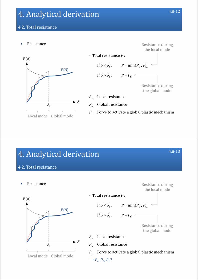
‐ Total resistance P :
If δ < δt : P = min(PL ; PG)
If δ > δt : P = PG
4.8‐12
Resistanceduringthelocalmode
Resistanceduringtheglobalmode
PL Local resistance
PG Global resistance
Pt Force to activate a global plastic mechanismLocalmode Globalmode
4.Analytical derivation4.2.Totalresistance
• Resistance
‐ Total resistance P :
If δ < δt : P = min(PL ; PG)
If δ > δt : P = PG
4.8‐13
Resistanceduringthelocalmode
Resistanceduringtheglobalmode
PL Local resistance
PG Global resistance
Pt Force to activate a global plastic mechanism
⟶ PL, PG, Pt ?Localmode Globalmode

4.Analytical derivation
4.1. Deformation sequence
4.2. Totalresistance
4.3. Localresistance
4.4. Globalresistance
4.5. Summary
4.9
4.Analytical derivation4.3.Localresistance
4.10‐1
• Reminder
Decomposition of the total resistance P :
‐ If δ < δt : P = min(PL ; PG)
‐ If δ < δt : P = PG

4.Analytical derivation4.3.Localresistance
4.10‐2
• Reminder
Decomposition of the total resistance P :
‐ If δ < δt : P = min(PL ; PG)
‐ If δ < δt : P = PG
4.Analytical derivation4.3.Localresistance
4.10‐3
Localresistance
• Reminder
Decomposition of the total resistance P :
‐ If δ < δt : P = min(PL ; PG)
‐ If δ < δt : P = PG

4.Analytical derivation4.3.Localresistance
• Decomposition of the gate into large entities
4.11‐1
4.Analytical derivation4.3.Localresistance
• Decomposition of the gate into large entities
• Gate = assembly of super‐elements
‐ SE1: Plating
4.11‐2
4.Analytical derivation4.3.Localresistance
• Decomposition of the gate into large entities
• Gate = assembly of super‐elements
‐ SE1: Plating
‐ SE2: Horizontal girdersVertical frames
4.11‐3
4.Analytical derivation4.3.Localresistance
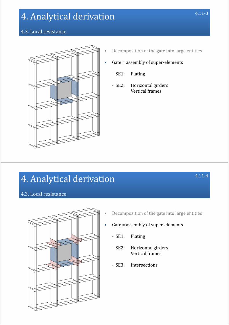
• Decomposition of the gate into large entities
• Gate = assembly of super‐elements
‐ SE1: Plating
‐ SE2: Horizontal girdersVertical frames
‐ SE3: Intersections
4.11‐4

4.Analytical derivation4.3.Localresistance
SE2
SE1
SE3• Three super‐element types:
‐ SE1: Plating
‐ SE2: VerticalframesHorizontalgirders
‐ SE3: Intersections
• Hypothesis: all the super‐elements are decoupled
4.12‐1
4.Analytical derivation4.3.Localresistance
SE2
SE1
SE3• Three super‐element types:
‐ SE1: Plating
‐ SE2: VerticalframesHorizontalgirders
‐ SE3: Intersections
• Hypothesis: all the super‐elements are decoupled
⟶ No interaction
Activation only if contact with the bow
4.12‐2

4.Analytical derivation4.3.Localresistance
• Decoupling⟶ hypothesis on the boundary conditions:
‐ SE1: Plate supported on four edges
Out‐of‐plane impact load
4.13‐1
4.Analytical derivation4.3.Localresistance
• Decoupling⟶ hypothesis on the boundary conditions:
‐ SE1: Plate supported on four edges
Out‐of‐plane impact load
‐ SE2: Plate supported on three edges
In‐plane impact load
4.13‐2

4.Analytical derivation4.3.Localresistance
• Decoupling⟶ hypothesis on the boundary conditions:
‐ SE1: Plate supported on four edges
Out‐of‐plane impact load
‐ SE2: Plate supported on three edges
In‐plane impact load
‐ SE3: X or T elements supported along their axis
Impacted along their axis
4.13‐3
4.Analytical derivation4.3.Localresistance
• How to evaluate the local resistance PL?
‐ Boundary conditions
‐ Geometrical properties
‐ Mechanical properties
SE1
SE2
SE3
Closed‐formexpressions
Super‐element i ResistancePi
4.14‐1

4.Analytical derivation4.3.Localresistance
• How to evaluate the local resistance PL?
‐ Boundary conditions
‐ Geometrical properties
‐ Mechanical properties
SE1
SE2
SE3
Closed‐formexpressions
Super‐element i ResistancePi
4.14‐2
4.Analytical derivation4.3.Localresistance
• How to evaluate the local resistance PL?
‐ Boundary conditions
‐ Geometrical properties
‐ Mechanical properties
SE1
SE2
SE3
Closed‐formexpressions
‐ Upper‐bound method
‐ Equilibrium method
4.14‐3
4.Analytical derivation4.3.Localresistance
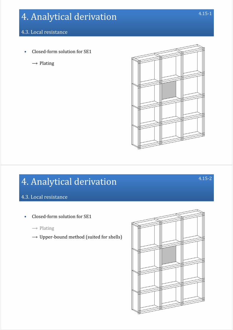
• Closed‐form solution for SE1
⟶ Plating
4.15‐1
4.Analytical derivation4.3.Localresistance
• Closed‐form solution for SE1
⟶ Plating
⟶ Upper‐bound method (suited for shells)
4.15‐2

4.Analytical derivation4.3.Localresistance
• Closed‐form solution for SE1
⟶ Plating
⟶ Upper‐bound method (suited for shells)
⟶ Write an energy balance:
4.15‐3
4.Analytical derivation4.3.Localresistance
• Closed‐form solution for SE1 (Plating)
1. Postulate u(y,z)
‐ Boundary conditions
‐ Geometry: a1, a2, b1, b2
‐ Bow shape
⟶ Realistic
4.16‐1

4.Analytical derivation4.3.Localresistance
• Closed‐form solution for SE1 (Plating)
1. Postulate u(y,z)
2. Calculate the strain rates
4.16‐2
4.Analytical derivation4.3.Localresistance
• Closed‐form solution for SE1 (Plating)
1. Postulate u(y,z)
2. Calculate the strain rates
3. Calculate the plastic internal energy rate
4.16‐3
4.Analytical derivation4.3.Localresistance
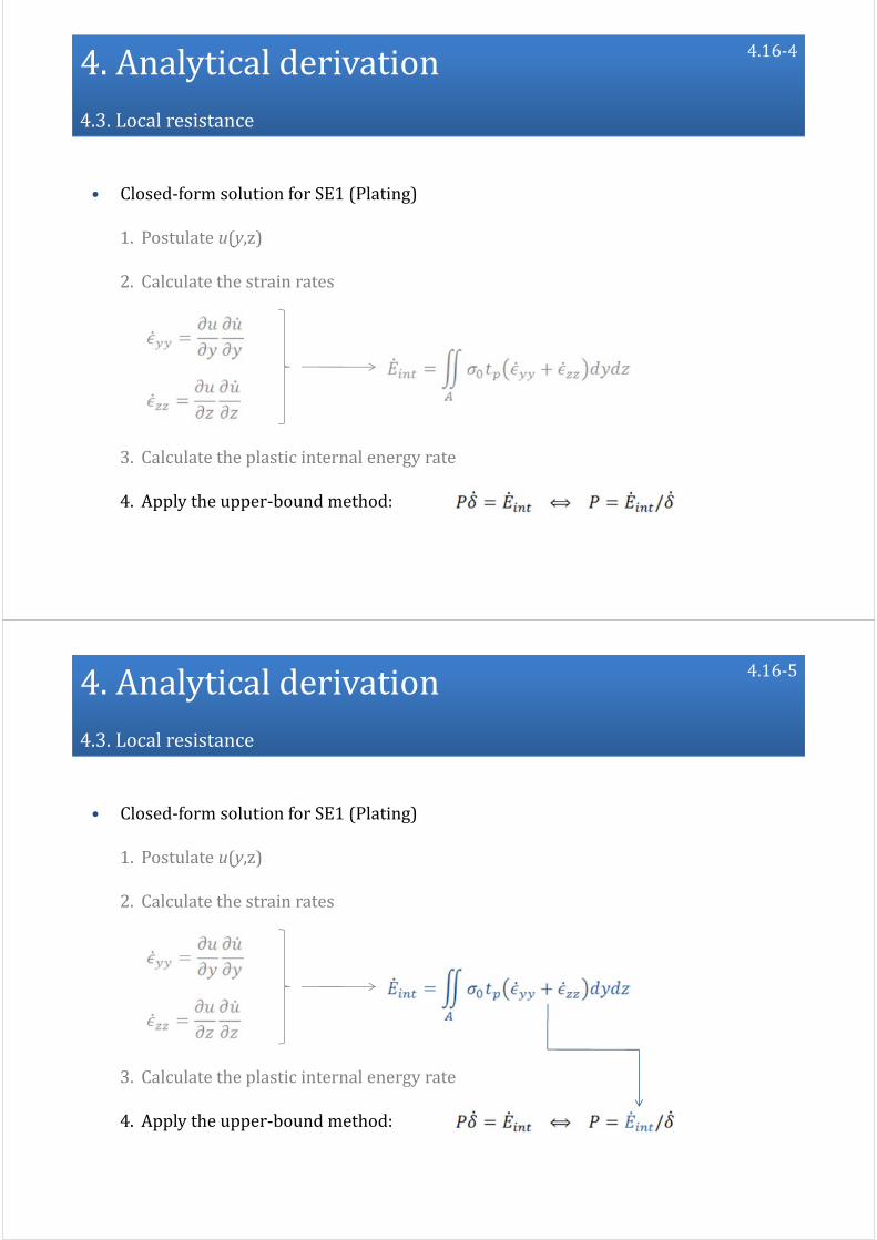
• Closed‐form solution for SE1 (Plating)
1. Postulate u(y,z)
2. Calculate the strain rates
3. Calculate the plastic internal energy rate
4. Apply the upper‐bound method:
4.16‐4
4.Analytical derivation4.3.Localresistance
• Closed‐form solution for SE1 (Plating)
1. Postulate u(y,z)
2. Calculate the strain rates
3. Calculate the plastic internal energy rate
4. Apply the upper‐bound method:
4.16‐5

4.Analytical derivation4.3.Localresistance
• Closed‐form solution for SE1 (Plating)
1. Postulate u(y,z)
2. Calculate the strain rates
3. Calculate the plastic internal energy rate
4. Apply the upper‐bound method:
SE1resistance
4.16‐6
4.Analytical derivation4.3.Localresistance
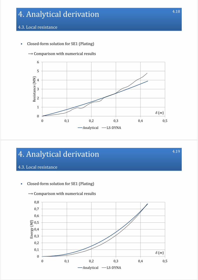
• Closed‐form solution for SE1 (Plating)
⟶ Comparison with numerical results
4.17
4.Analytical derivation4.3.Localresistance
• Closed‐form solution for SE1 (Plating)
⟶ Comparison with numerical results
0
1
2
3
4
5
6
0 0,1 0,2 0,3 0,4 0,5
Resistance(MN)
δ (m)
Analytical LS‐DYNA
4.18
4.Analytical derivation4.3.Localresistance
• Closed‐form solution for SE1 (Plating)
⟶ Comparison with numerical results
0
0,1
0,2
0,3
0,4
0,5
0,6
0,7
0,8
0 0,1 0,2 0,3 0,4 0,5
Energy(MJ)
δ (m)
Analytical LS‐DYNA
4.19
4.Analytical derivation4.3.Localresistance
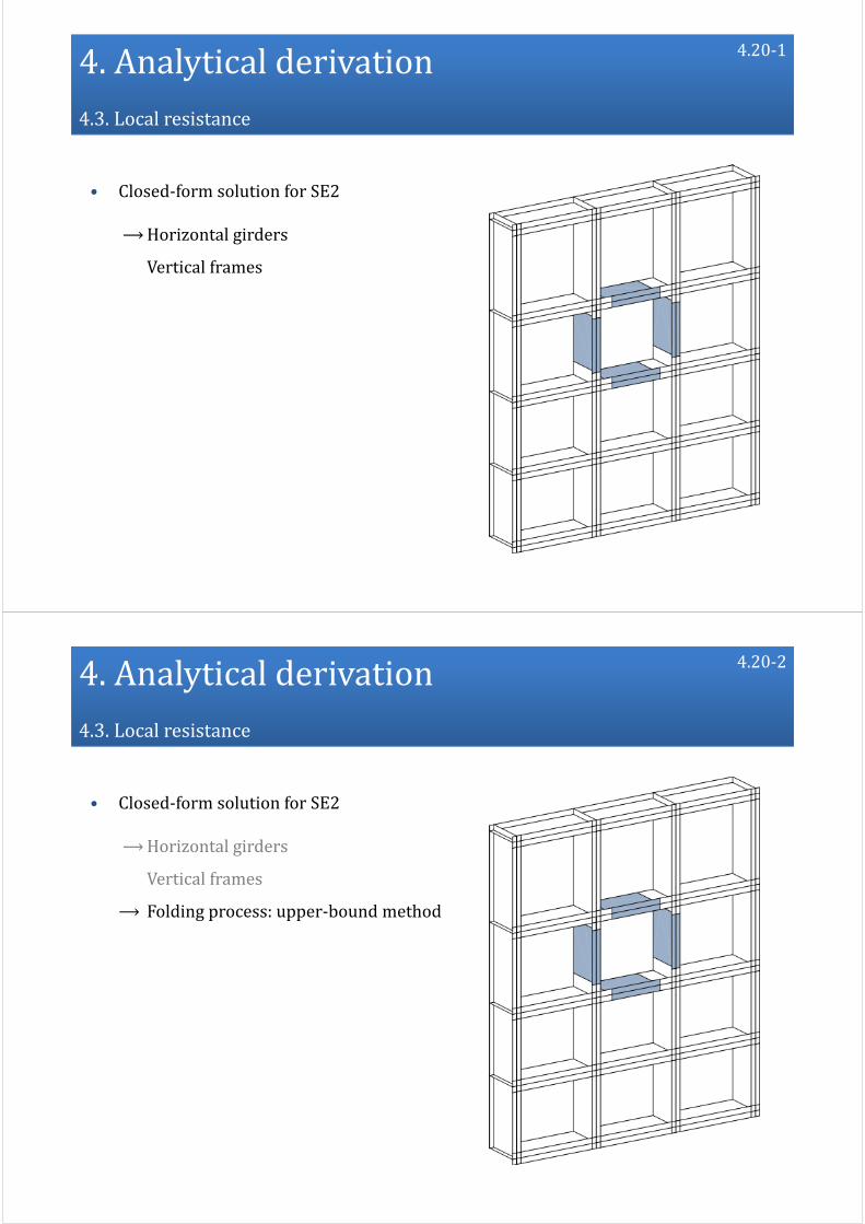
• Closed‐form solution for SE2
⟶Horizontal girders
Vertical frames
4.20‐1
4.Analytical derivation4.3.Localresistance
• Closed‐form solution for SE2
⟶Horizontal girders
Vertical frames
⟶ Folding process: upper‐bound method
4.20‐2

4.Analytical derivation4.3.Localresistance
• Closed‐form solution for SE2
⟶Horizontal girders
Vertical frames
⟶ Folding process: upper‐bound method
⟶ Beam behaviour: equilibrium method
4.20‐3
4.Analytical derivation4.3.Localresistance
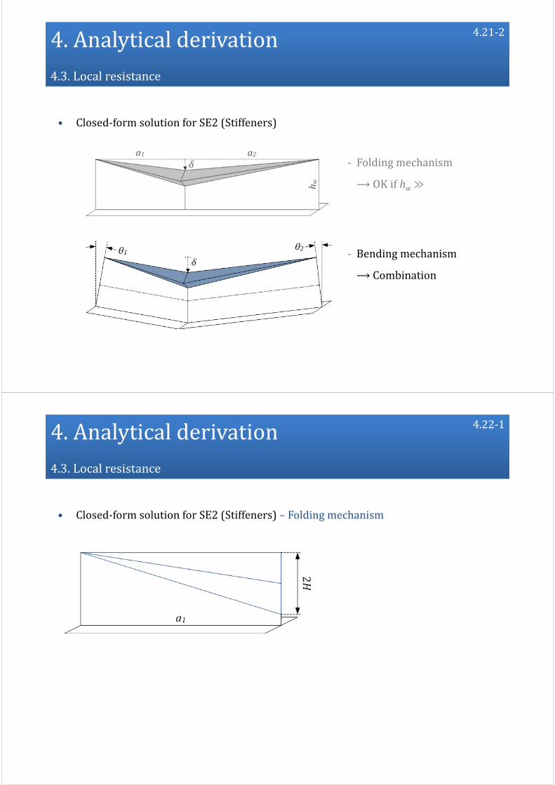
• Closed‐form solution for SE2 (Stiffeners)
‐ Folding mechanism
⟶OK if hw≫
4.21‐1
4.Analytical derivation4.3.Localresistance
• Closed‐form solution for SE2 (Stiffeners)
‐ Folding mechanism
⟶OK if hw≫
‐ Bending mechanism
⟶ Combination
4.21‐2
4.Analytical derivation4.3.Localresistance
• Closed‐form solution for SE2 (Stiffeners) – Folding mechanism
4.22‐1

4.Analytical derivation4.3.Localresistance
• Closed‐form solution for SE2 (Stiffeners) – Folding mechanism
‐ Two triangles of height H
4.22‐2
4.Analytical derivation4.3.Localresistance
• Closed‐form solution for SE2 (Stiffeners) – Folding mechanism
‐ Two triangles
‐ Three plastic hinges
4.22‐3
4.Analytical derivation4.3.Localresistance
• Closed‐form solution for SE2 (Stiffeners) – Folding mechanism
‐ Two triangles
‐ Three plastic hinges
⟶ Rotation in the hinges
Bending energy rate Ėb
4.22‐4
4.Analytical derivation4.3.Localresistance
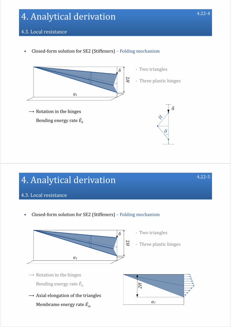
• Closed‐form solution for SE2 (Stiffeners) – Folding mechanism
‐ Two triangles
‐ Three plastic hinges
⟶ Rotation in the hinges
Bending energy rate Ėb
⟶ Axial elongation of the triangles
Membrame energy rate Ėm
4.22‐5

4.Analytical derivation4.3.Localresistance
• Closed‐form solution for SE2 (Stiffeners) – Folding mechanism
‐ Two triangles
‐ Three plastic hinges
⟶ Rotation in the hinges
Bending energy rate Ėb
⟶ Axial straining of the triangles
Membrame energy rate Ėm
Folding resistance
4.22‐6
4.Analytical derivation4.3.Localresistance
• Closed‐form solution for SE2 (Stiffeners) – Transition
‐ The central section is crushed during the folding process
4.23‐1

4.Analytical derivation4.3.Localresistance
• Closed‐form solution for SE2 (Stiffeners) – Transition
‐ The central section is crushed during the folding process
‐ The residual bending strength is:
Fullcross‐sectionbending strength
4.23‐2
4.Analytical derivation4.3.Localresistance
• Closed‐form solution for SE2 (Stiffeners) – Transition
‐ The central section is crushed during the folding process
‐ The residual bending strength is:
Reductioncoefficient
Fullcross‐sectionbending strength
4.23‐3
4.Analytical derivation4.3.Localresistance
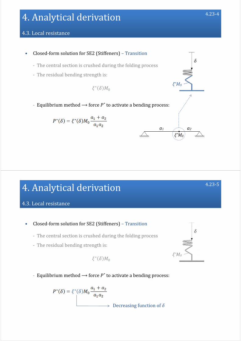
• Closed‐form solution for SE2 (Stiffeners) – Transition
‐ The central section is crushed during the folding process
‐ The residual bending strength is:
‐ Equilibrium method⟶ force P * to activate a bending process:
4.23‐4
4.Analytical derivation4.3.Localresistance
• Closed‐form solution for SE2 (Stiffeners) – Transition
‐ The central section is crushed during the folding process
‐ The residual bending strength is:
‐ Equilibrium method⟶ force P * to activate a bending process:
Decreasing function ofδ
4.23‐5
4.Analytical derivation4.3.Localresistance
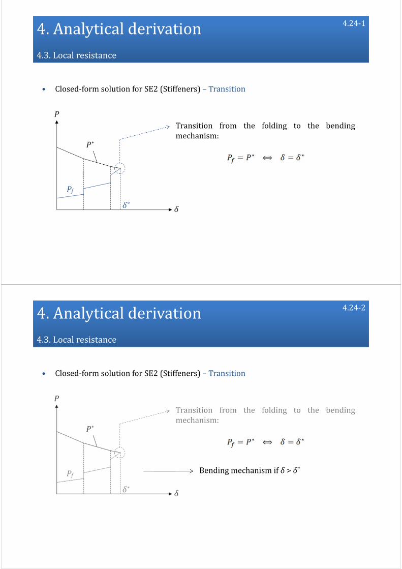
• Closed‐form solution for SE2 (Stiffeners) – Transition
Transition from the folding to the bendingmechanism:
4.24‐1
4.Analytical derivation4.3.Localresistance
• Closed‐form solution for SE2 (Stiffeners) – Transition
Transition from the folding to the bendingmechanism:
Bending mechanism if δ > δ*
4.24‐2

4.Analytical derivation4.3.Localresistance
• Closed‐form solution for SE2 (Stiffeners) – Bending mechanism
‐ Bending mechanism if δ > δ*
4.25‐1
4.Analytical derivation4.3.Localresistance
• Closed‐form solution for SE2 (Stiffeners) – Bending mechanism
‐ Bending mechanism if δ > δ*
‐ Reduced bending moment in the central section
4.25‐2

4.Analytical derivation4.3.Localresistance
• Closed‐form solution for SE2 (Stiffeners) – Bending mechanism
‐ Bending mechanism if δ > δ*
‐ Reduced bending moment in the central section
‐ Moderate displacements⟶ tensile membrane forces
4.25‐3
4.Analytical derivation4.3.Localresistance
• Closed‐form solution for SE2 (Stiffeners) – Bending mechanism
‐ Bending mechanism if δ > δ*
‐ Reduced bending moment in the central section
‐ Moderate displacements⟶ tensile membrane forces
‐ Static equilibrium of the beam⟶ bending resistance Pb
4.25‐4
4.Analytical derivation4.3.Localresistance
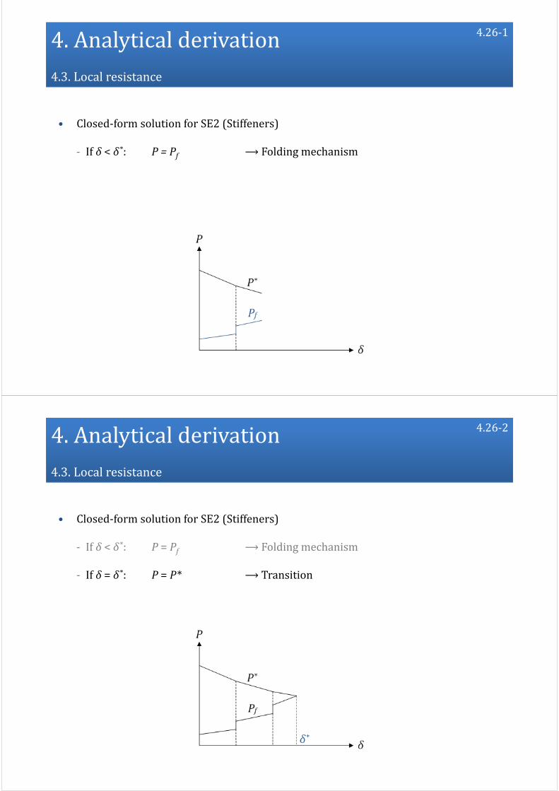
• Closed‐form solution for SE2 (Stiffeners)
‐ If δ < δ*: P = Pf ⟶Folding mechanism
4.26‐1
4.Analytical derivation4.3.Localresistance
• Closed‐form solution for SE2 (Stiffeners)
‐ If δ < δ*: P = Pf ⟶Folding mechanism
‐ If δ = δ*: P = P* ⟶ Transition
4.26‐2

4.Analytical derivation4.3.Localresistance
• Closed‐form solution for SE2 (Stiffeners)
‐ If δ < δ*: P = Pf ⟶Folding mechanism
‐ If δ = δ*: P = P* ⟶ Transition
‐ If δ > δ*: P = Pb ⟶Bending mechanism
4.26‐3
4.Analytical derivation4.3.Localresistance
• Closed‐form solution for SE2 (Stiffeners)
‐ If δ < δ*: P = Pf ⟶Folding mechanism
‐ If δ = δ*: P = P* ⟶ Transition
‐ If δ > δ*: P = Pb ⟶Bending mechanism
4.26‐4

4.Analytical derivation4.3.Localresistance
• Closed‐form solution for SE2 (Stiffeners)
⟶ Comparison with numerical results
4.27‐1
4.Analytical derivation4.3.Localresistance
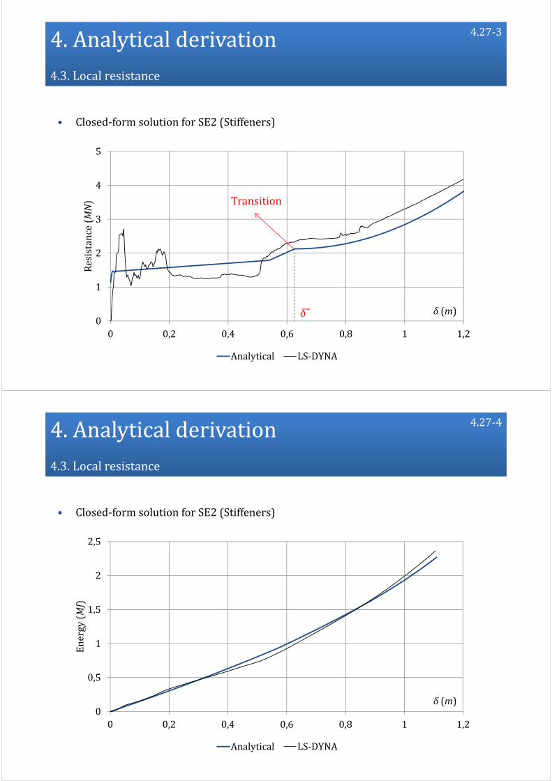
• Closed‐form solution for SE2 (Stiffeners)
0
1
2
3
4
5
0 0,2 0,4 0,6 0,8 1 1,2
Resistance(MN)
δ (m)
Analytical LS‐DYNA
4.27‐2
4.Analytical derivation4.3.Localresistance
0
1
2
3
4
5
0 0,2 0,4 0,6 0,8 1 1,2
Resistance(MN)
δ (m)
Analytical LS‐DYNA
• Closed‐form solution for SE2 (Stiffeners)
δ*
Transition
4.27‐3
4.Analytical derivation4.3.Localresistance
0
0,5
1
1,5
2
2,5
0 0,2 0,4 0,6 0,8 1 1,2
Energy(MJ)
δ (m)
Analytical LS‐DYNA
• Closed‐form solution for SE2 (Stiffeners)
4.27‐4

4.Analytical derivation4.3.Localresistance
• Closed‐form solution for SE3
⟶ Intersections
4.28‐1
4.Analytical derivation4.3.Localresistance
• Closed‐form solution for SE3
⟶ Intersections
⟶ Folding process: upper‐bound method
4.28‐2

4.Analytical derivation4.3.Localresistance
• Closed‐form solution for SE3
⟶ Intersections
⟶ Folding process: upper‐bound method
⟶ Beam behaviour: equilibrium method
4.28‐3
4.Analytical derivation4.3.Localresistance
• Closed‐form solution for SE3 (Intersections)
‐ Folding mechanism
‐ Bending mechanism
4.29

4.Analytical derivation4.3.Localresistance
• Closed‐form solution for SE3 (Intersections) – Folding mechanism
‐ 4wings aresimultaneously crushed
‐ Each wing is madeoftwo parts:
4.30‐1
4.Analytical derivation4.3.Localresistance
• Closed‐form solution for SE3 (Intersections) – Folding mechanism
‐ 4wings aresimultaneously crushed
‐ Each wing is madeoftwo parts:
① Centralpart
4.30‐2

4.Analytical derivation4.3.Localresistance
• Closed‐form solution for SE3 (Intersections) – Folding mechanism
‐ 4wings aresimultaneously crushed
‐ Each wing is madeoftwo parts:
① Centralpart
② Connectionpart
4.30‐3
4.Analytical derivation4.3.Localresistance
• Closed‐form solution for SE3 (Intersections) – Folding mechanism
⟶Upper‐bound method: 1. Compatibledisplacement field for① and②
4.31‐1

4.Analytical derivation4.3.Localresistance
• Closed‐form solution for SE3 (Intersections) – Folding mechanism
⟶Upper‐bound method: 1. Compatibledisplacement field for① and②
2. MembraneenergyrateĖm
Membrane deformationsinthetriangles+bendingintheplastichinges
4.31‐2
4.Analytical derivation4.3.Localresistance
• Closed‐form solution for SE3 (Intersections) – Folding mechanism
⟶Upper‐bound method: 1. Compatibledisplacement field for① and②
2. MembraneenergyrateĖm
3. BendingenergyrateĖb
Membranedeformationsinthetriangles +bending intheplastichinges
4.31‐3

4.Analytical derivation4.3.Localresistance
• Closed‐form solution for SE3 (Intersections) – Folding mechanism
⟶Upper‐bound method: 1. Compatibledisplacement field for① and②
2. MembraneenergyrateĖm
3. BendingenergyrateĖb
⟶Totalinternal energy:
Folding resistance
4.31‐4
4.Analytical derivation4.3.Localresistance
• Closed‐form solution for SE3 (Intersections) – Bending mechanism
‐ Forδ =δ*: Transition
‐ Forδ >δ*: Bending mechanism
Displacement ofthenodalpoint
4.32‐1

4.Analytical derivation4.3.Localresistance
• Closed‐form solution for SE3 (Intersections) – Bending mechanism
‐ Each wing is submitted tobending
4.32‐2
4.Analytical derivation4.3.Localresistance
• Closed‐form solution for SE3 (Intersections) – Bending mechanism
‐ Each wing is submitted tobending
‐ Reduced bending resistance ξ*M0
4.32‐3

4.Analytical derivation4.3.Localresistance
• Closed‐form solution for SE3 (Intersections) – Bending mechanism
‐ Each wing is submitted tobending
‐ Reduced bending resistance ξ*M0
‐ Additional membraneforces
Equilibrium method⟶ bending resistance Pb
4.32‐4
4.Analytical derivation4.3.Localresistance
• Closed‐form solution for SE3 (Intersections)
‐ If δ < δ*: P = Pf ⟶Folding mechanism
‐ If δ = δ*: P = P* ⟶ Transition
‐ If δ > δ*: P = Pb ⟶Bending mechanism
4.33

4.Analytical derivation4.3.Localresistance
• Closed‐form solution for SE3 (Intersections)
⟶ Comparison with numerical results
4.34
4.Analytical derivation4.3.Localresistance
• Closed‐form solution for SE3 (Intersections)
0
1000
2000
3000
4000
5000
6000
7000
8000
0 0,2 0,4 0,6 0,8 1 1,2
Resistance(kN)
δ (m)
Analytical
LS‐DYNA
4.35‐1

4.Analytical derivation4.3.Localresistance
• Closed‐form solution for SE3 (Intersections)
0
1000
2000
3000
4000
5000
6000
7000
8000
0 0,2 0,4 0,6 0,8 1 1,2
Resistance(kN)
δ (m)
Analytical
LS‐DYNA
δ*
Transition
4.35‐2
4.Analytical derivation4.3.Localresistance
• Closed‐form solution for SE3 (Intersections)
0
0,5
1
1,5
2
2,5
0 0,2 0,4 0,6 0,8 1 1,2
Energy(MJ)
δ (m)
Analytical
LS‐DYNA
4.36

4.Analytical derivation4.3.Localresistance
• Local resistance calculation
4.37‐1
4.Analytical derivation4.3.Localresistance
• Local resistance calculation
4.37‐2
Totalnumber ofsuper‐elements

4.Analytical derivation4.3.Localresistance
• Local resistance calculation
4.37‐3
Totalnumber ofsuper‐elements
‐ Pi = 0 if the super‐element is not activated
‐ Pi ≠ 0 if the super‐element is impacted by the bow
⟶ analytical formulae of SE1, SE2 or SE3
Individual resistance ofeach super‐element:
4.Analytical derivation
4.1. Deformation sequence
4.2. Totalresistance
4.3. Localresistance
4.4. Globalresistance
4.5. Summary
4.38

4.Analytical derivation4.4.Globalresistance
4.39‐1
• Reminder
Decomposition of the total resistance P :
‐ If δ < δt : P = min(PL ; PG)
‐ If δ < δt : P = PG
4.Analytical derivation4.4.Globalresistance
4.39‐2
• Reminder
Decomposition of the total resistance P :
‐ If δ < δt : P = min(PL ; PG)
‐ If δ < δt : P = PG

4.Analytical derivation4.4.Globalresistance
4.39‐3
Globalresistance
• Reminder
Decomposition of the total resistance P :
‐ If δ < δt : P = min(PL ; PG)
‐ If δ < δt : P = PG
4.Analytical derivation4.4.Globalresistance
• Local deforming mode:
‐ Decoupled super‐elements
‐ Idealized boundary conditions
4.40‐1

4.Analytical derivation4.4.Globalresistance
• Local deforming mode:
‐ Decoupled super‐elements
‐ Idealized boundary conditions
⟶ Able to capture the localized crushing
4.40‐2
4.Analytical derivation4.4.Globalresistance
• Local deforming mode:
‐ Decoupled super‐elements
‐ Idealized boundary conditions
⟶ Able to capture the localized crushing
⟶ Unable to capture the overall bending
Globalmode
4.40‐3

4.Analytical derivation4.4.Globalresistance
• Observations:
‐ The frames ∼ rotate as rigid bodies
4.41
4.Analytical derivation4.4.Globalresistance
• Observations during the global mode:
‐ The frames ∼ rotate as rigid bodies
‐ They do not dissipate a lot of energy
4.42‐1

4.Analytical derivation4.4.Globalresistance
• Observations during the global mode:
‐ The frames ∼ rotate as rigid bodies
‐ They do not dissipate a lot of energy
Localmode(crushing)
4.42‐2
4.Analytical derivation4.4.Globalresistance
• Observations during the global mode:
‐ The frames ∼ rotate as rigid bodies
‐ They do not dissipate a lot of energy
Globalmode(rotation)
4.42‐3

4.Analytical derivation4.4.Globalresistance
• Observations during the global mode:
‐ The frames ∼ rotate as rigid bodies
‐ They do not dissipate a lot of energyNegligible contributiontoPG
4.42‐4
4.Analytical derivation4.4.Globalresistance
• Observations during the global mode:
‐ The frames ∼ rotate as rigid bodies
‐ They do not dissipate a lot of energy
• Energy dissipated during the global mode
= Contribution from the girders
Negligible contributiontoPG
4.42‐5

4.Analytical derivation4.4.Globalresistance
• Observations during the global mode:
‐ The frames ∼ rotate as rigid bodies
‐ They do not dissipate a lot of energy
• Energy dissipated during the global mode
= Contribution from the girders
the plating
Negligible contributiontoPG
4.42‐6
4.Analytical derivation4.4.Globalresistance
• Observations during the global mode:
‐ The frames ∼ rotate as rigid bodies
‐ They do not dissipate a lot of energy
• Energy dissipated during the global mode
= Contribution from the girders
the plating
the stiffeners
Negligible contributiontoPG
4.42‐7
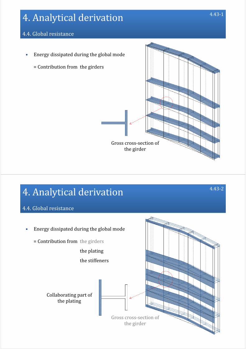
4.Analytical derivation4.4.Globalresistance
• Energy dissipated during the global mode
= Contribution from the girders
Grosscross‐sectionofthegirder
4.43‐1
4.Analytical derivation4.4.Globalresistance
• Energy dissipated during the global mode
= Contribution from the girders
the plating
the stiffeners
Grosscross‐sectionofthegirder
Collaborating partoftheplating
4.43‐2

4.Analytical derivation4.4.Globalresistance
• Gate model
‐ Set of horizontal beams
4.43‐3
4.Analytical derivation4.4.Globalresistance
• Gate model
‐ Set of horizontal beams
‐ Connected by the frames
4.43‐4

4.Analytical derivation4.4.Globalresistance
• Gate model
‐ Set of horizontal beams
‐ Connected by the frames
‐ Submitted to
4.43‐5
4.Analytical derivation4.4.Globalresistance
• Gate model
‐ Set of horizontal beams
‐ Connected by the frames
‐ Submitted to
an out‐of‐plane displacement field u
4.43‐6

4.Analytical derivation4.4.Globalresistance
• Gate model
‐ Set of horizontal beams
‐ Connected by the frames
‐ Submitted to
an out‐of‐plane displacement field u
an in‐plane displacement field w
4.43‐7
4.Analytical derivation4.4.Globalresistance
• Gate model
‐ Set of horizontal beams
‐ Connected by the frames
‐ Submitted to
an out‐of‐plane displacement field u
an in‐plane displacement field w
Impactlocation
Bowshape
Bulb
Sill
4.43‐8

4.Analytical derivation4.4.Globalresistance
• Gate model
‐ Set of horizontal beams
‐ Connected by the frames
‐ Submitted to
an out‐of‐plane displacement field u
an in‐plane displacement field w
• Global resistance
4.43‐9
4.Analytical derivation4.4.Globalresistance
• Mechanical model of a beam i
4.43‐10

4.Analytical derivation4.4.Globalresistance
• Mechanical model of a beam i
4.43‐11
4.Analytical derivation4.4.Globalresistance
• Mechanical model of a beam i
⟶Beam theory with u and w
4.43‐12

4.Analytical derivation4.4.Globalresistance
• Mechanical model of a beam i
⟶Beam theory with u and w
⟶Individual resistance Pi of beam i
4.43‐13
4.Analytical derivation4.4.Globalresistance
• Mechanical model of a beam i
⟶Beam theory with u and w
⟶Individual resistance Pi of beam iElastic
Plastic
4.43‐14

4.Analytical derivation4.4.Globalresistance
• Mechanical model of a beam i
⟶Beam theory with u and w
⟶Individual resistance Pi of beam iElastic⟶Resistanceduring thelocal mode
Plastic⟶Resistanceduring theglobalmode
4.43‐15
Localmode Globalmode
4.Analytical derivation4.4.Globalresistance
• Mechanical model of a beam i
⟶Beam theory with u and w
⟶Individual resistance Pi of beam iElastic⟶Resistanceduring thelocalmode
Plastic⟶Resistanceduring theglobal mode
4.43‐16
Localmode Global mode
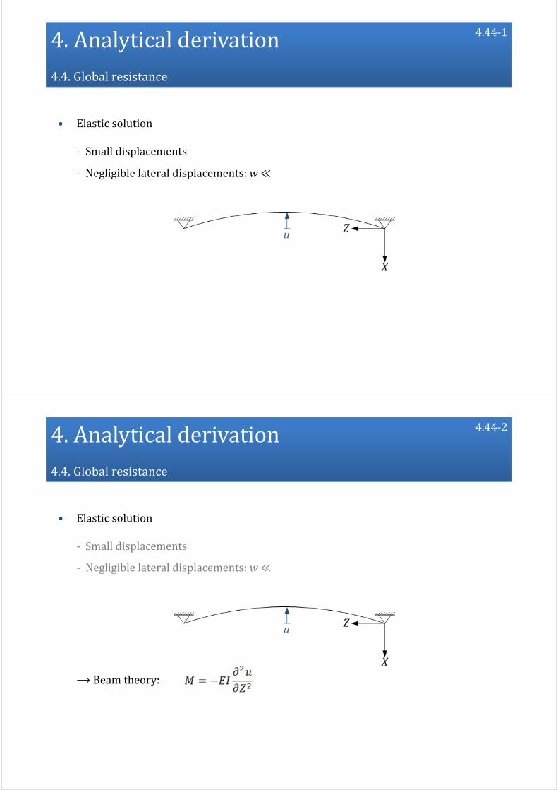
4.Analytical derivation4.4.Globalresistance
• Elastic solution
‐ Small displacements
‐ Negligible lateral displacements: w≪
4.44‐1
4.Analytical derivation4.4.Globalresistance
• Elastic solution
‐ Small displacements
‐ Negligible lateral displacements: w≪
⟶Beam theory:
4.44‐2

4.Analytical derivation4.4.Globalresistance
• Elastic solution
‐ Small displacements
‐ Negligible lateral displacements: w≪
⟶Beam theory:
⟶ Equilibrium method to get an elastic solution for Pi
Localindentation
4.44‐3
4.Analytical derivation4.4.Globalresistance
• Elastic solution
‐ Small displacements
‐ Negligible lateral displacements: w≪
⟶Beam theory:
⟶ Equilibrium method to get an elastic solution for Pi
Localindentation
Maynotexceedthecross‐sectionbendingresistance
4.44‐4

4.Analytical derivation4.4.Globalresistance
• Elastic solution
‐ Small displacements
‐ Negligible lateral displacements: w≪
⟶Beam theory:
⟶ Equilibrium method to get an elastic solution for Pi
Localindentation
Maynotexceedthecross‐sectionbendingresistance
Classification
4.44‐5
4.Analytical derivation4.4.Globalresistance
• Elastic solution
‐ If the girder is simultaneously crushed during the local mode
Localindentation
4.46‐1
Bending resistance isreached

4.Analytical derivation4.4.Globalresistance
• Elastic solution
‐ If the girder is simultaneously crushed during the local mode
Localindentation
Decreasingresistanceuntilδ =δt(globalplasticmechanism)
4.46‐2
4.Analytical derivation4.4.Globalresistance
• Elastic solution
‐ If the girder is simultaneously crushed during the local mode
‐ If the girder is not crushed during the local mode
Bendingresistanceisreached
Nolocalindentation
4.46‐3

4.Analytical derivation4.4.Globalresistance
• Elastic solution
‐ If the girder is simultaneously crushed during the local mode
‐ If the girder is not crushed during the local mode
Nolocalindentation
4.46‐4
Constantresistanceuntilδ =δt(globalplasticmechanism)
4.Analytical derivation4.4.Globalresistance
• Plastic solution
‐ If the bending resistance is reached for all the beams⟶ δ = δt
4.46‐5
δ =δt aglobalplasticmechanism isactivated overtheentire gate

4.Analytical derivation4.4.Globalresistance
• Plastic solution
‐ If the bending resistance is reached for all the beams⟶ δ = δt
‐ A plastic solution is needed to calculate PGwhen δ > δt
4.46‐6
Need aplasticsolutionforPG ifδ >δt
? ?
4.Analytical derivation4.4.Globalresistance
• Plastic solution
‐ Lateral displacements w1 and w2
‐ Out‐of‐plane displacement u
4.47‐1

4.Analytical derivation4.4.Globalresistance
• Plastic solution
‐ Lateral displacements w1 and w2
‐ Out‐of‐plane displacement u
‐ Membrane force N
4.47‐2
4.Analytical derivation4.4.Globalresistance
• Plastic solution
‐ Lateral displacements w1 and w2
‐ Out‐of‐plane displacement u
‐ Membrane force N
‐ Rotation θ
4.47‐3

4.Analytical derivation4.4.Globalresistance
• Plastic solution
‐ Lateral displacements w1 and w2
‐ Out‐of‐plane displacement u
‐ Membrane force N
‐ Rotation θ
Plastichinge(Class1)
4.47‐4
4.Analytical derivation4.4.Globalresistance
• Plastic solution
‐ Class 1: plastic resistances ξpMp and Np
4.48‐1

4.Analytical derivation4.4.Globalresistance
• Plastic solution
‐ Class 1: plastic resistances ξpMp and Np
‐ Interaction criteria forM and N
4.48‐2
4.Analytical derivation4.4.Globalresistance
• Plastic solution
‐ Class 1: plastic resistances ξpMp and Np
‐ Interaction criteria forM and N
‐ Equilibrium method⟶ Pi
4.48‐3

4.Analytical derivation4.4.Globalresistance
• Plastic solution
‐ Lateral displacements w1 and w2
‐ Out‐of‐plane displacement u
‐ Membrane force N
‐ Rotation θ
Buckling(Class>1)
4.49‐1
4.Analytical derivation4.4.Globalresistance
• Plastic solution
‐ Class > 1: no plastic hinge but early buckling
⟶ Post‐buckling resistance: thin‐walled structure
4.49‐2
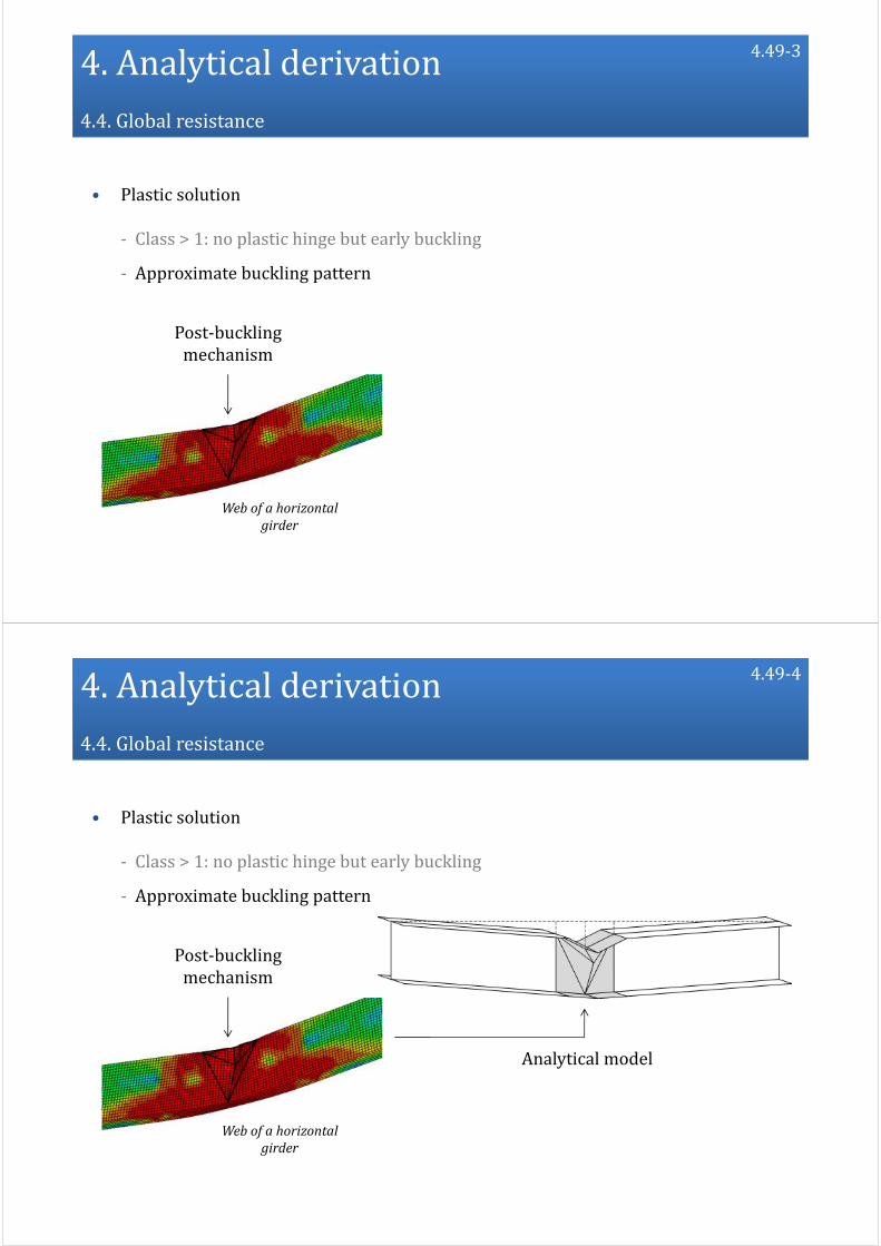
4.Analytical derivation4.4.Globalresistance
• Plastic solution
‐ Class > 1: no plastic hinge but early buckling
‐ Approximate buckling pattern
Webofahorizontalgirder
Post‐bucklingmechanism
4.49‐3
4.Analytical derivation4.4.Globalresistance
• Plastic solution
‐ Class > 1: no plastic hinge but early buckling
‐ Approximate buckling pattern
Webofahorizontalgirder
Post‐bucklingmechanism
Analyticalmodel
4.49‐4

4.Analytical derivation4.4.Globalresistance
• Plastic solution
‐ Class > 1: no plastic hinge but early buckling
‐ Approximate buckling pattern
4.49‐5
4.Analytical derivation4.4.Globalresistance
• Plastic solution
‐ Class > 1: no plastic hinge but early buckling
‐ Approximate buckling pattern
‐ Upper‐bound method⟶ Pi
4.49‐6

4.Analytical derivation4.4.Globalresistance
• Plastic solution
‐ If the girder has been previously crushed before the transition
Class1 Class>1
4.50‐1
? ?
4.Analytical derivation4.4.Globalresistance
• Plastic solution
‐ If the girder has been previously crushed before the transition
Class1 Class>1
4.50‐2

4.Analytical derivation4.4.Globalresistance
• Plastic solution
‐ If the girder has been previously crushed before the transition
‐ If the girder has not been crushed before the transition
Class1 Class>1
4.50‐3
? ?
4.Analytical derivation4.4.Globalresistance
• Plastic solution
‐ If the girder has been previously crushed before the transition
‐ If the girder has not been crushed before the transition
Class1 Class>1
4.50‐4

4.Analytical derivation4.4.Globalresistance
• Global resistance calculation
4.51‐1
4.Analytical derivation4.4.Globalresistance
• Global resistance calculation
4.51‐2
Totalnumber ofhorizontalbeams

4.Analytical derivation4.4.Globalresistance
• Global resistance calculation
4.51‐3
Totalnumber ofhorizontalbeams
‐ δ < δt : Elastic solution for Pi
‐ δ > δt : Plastic solution for Pi
Individual resistance ofeach beam:
4.Analytical derivation
4.1. Deformation sequence
4.2. Totalresistance
4.3. Localresistance
4.4. Globalresistance
4.5. Summary
4.52
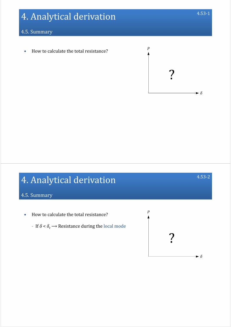
4.Analytical derivation4.5.Summary
• How to calculate the total resistance?
4.53‐1
4.Analytical derivation4.5.Summary
• How to calculate the total resistance?
‐ If δ < δt⟶Resistance during the local mode
4.53‐2
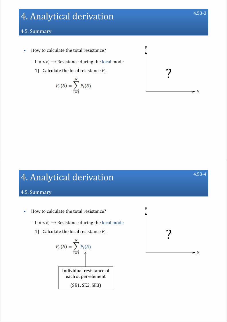
4.Analytical derivation4.5.Summary
• How to calculate the total resistance?
‐ If δ < δt⟶Resistance during the local mode
1) Calculate the local resistance PL
4.53‐3
4.Analytical derivation4.5.Summary
• How to calculate the total resistance?
‐ If δ < δt⟶Resistance during the local mode
1) Calculate the local resistance PL
4.53‐4
Individual resistance ofeach super‐element
(SE1,SE2,SE3)
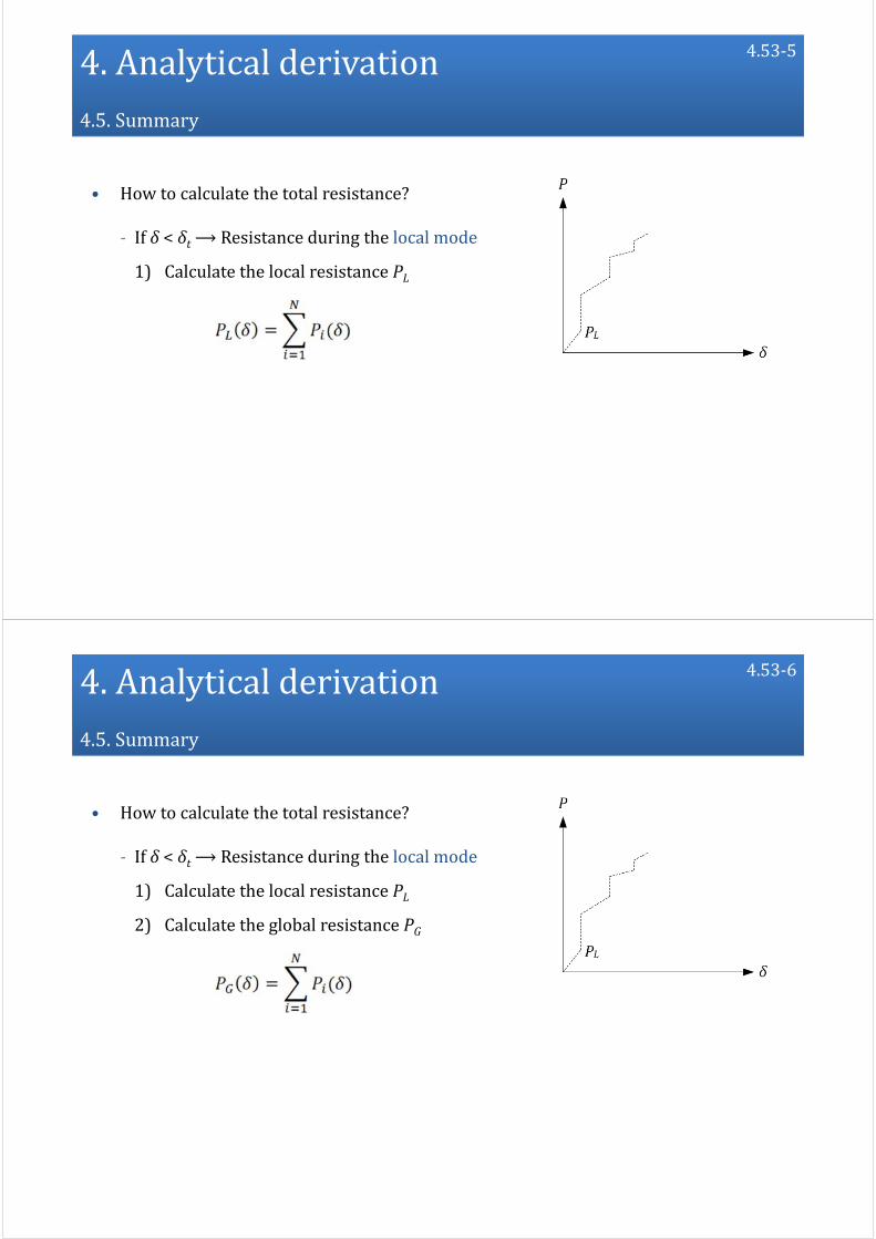
4.Analytical derivation4.5.Summary
• How to calculate the total resistance?
‐ If δ < δt⟶Resistance during the local mode
1) Calculate the local resistance PL
4.53‐5
4.Analytical derivation4.5.Summary
• How to calculate the total resistance?
‐ If δ < δt⟶Resistance during the local mode
1) Calculate the local resistance PL
2) Calculate the global resistance PG
4.53‐6
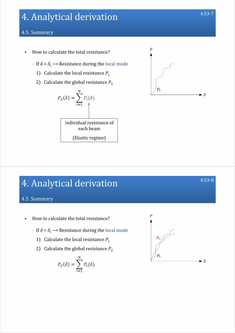
4.Analytical derivation4.5.Summary
• How to calculate the total resistance?
‐ If δ < δt⟶Resistance during the local mode
1) Calculate the local resistance PL
2) Calculate the global resistance PG
4.53‐7
Individual resistance ofeach beam
(Elastic regime)
4.Analytical derivation4.5.Summary
• How to calculate the total resistance?
‐ If δ < δt⟶Resistance during the local mode
1) Calculate the local resistance PL
2) Calculate the global resistance PG
4.53‐8

4.Analytical derivation4.5.Summary
• How to calculate the total resistance?
‐ If δ < δt⟶Resistance during the local mode
1) Calculate the local resistance PL
2) Calculate the global resistance PG
3) Calculate P = min(PL , PG)
4.53‐9
4.Analytical derivation4.5.Summary
• How to calculate the total resistance?
‐ If δ < δt⟶Resistance during the local mode
‐ If δ = δt⟶Transition
4.53‐10

4.Analytical derivation4.5.Summary
• How to calculate the total resistance?
‐ If δ < δt⟶Resistance during the local mode
‐ If δ = δt⟶Transition
1) Calculate the force to activate a global plasticmechanism Pt
4.53‐11
4.Analytical derivation4.5.Summary
• How to calculate the total resistance?
‐ If δ < δt⟶Resistance during the local mode
‐ If δ = δt⟶Transition
1) Calculate the force to activate a global plasticmechanism Pt
2) The transition occurs when P = min(PL , PG) = Pt
4.53‐12

4.Analytical derivation4.5.Summary
• How to calculate the total resistance?
‐ If δ < δt⟶Resistance during the local mode
‐ If δ = δt⟶Transition
‐ If δ < δt⟶Resistance during the global mode
4.53‐13
4.Analytical derivation4.5.Summary
• How to calculate the total resistance?
‐ If δ < δt⟶Resistance during the local mode
‐ If δ = δt⟶Transition
‐ If δ < δt⟶Resistance during the global mode
1) Calculate the global resistance PG
4.53‐14
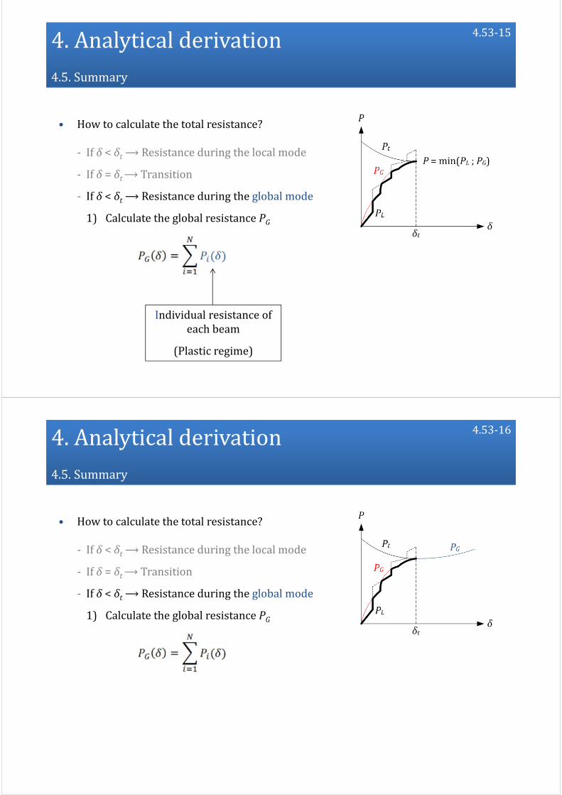
4.Analytical derivation4.5.Summary
• How to calculate the total resistance?
‐ If δ < δt⟶Resistance during the local mode
‐ If δ = δt⟶Transition
‐ If δ < δt⟶Resistance during the global mode
1) Calculate the global resistance PG
4.53‐15
Individual resistance ofeach beam
(Plasticregime)
4.Analytical derivation4.5.Summary
• How to calculate the total resistance?
‐ If δ < δt⟶Resistance during the local mode
‐ If δ = δt⟶Transition
‐ If δ < δt⟶Resistance during the global mode
1) Calculate the global resistance PG
4.53‐16

4.Analytical derivation4.5.Summary
• How to calculate the total resistance?
‐ If δ < δt⟶Resistance during the local mode
‐ If δ = δt⟶Transition
‐ If δ < δt⟶Resistance during the global mode
1) Calculate the global resistance PG
2) Calculate P = PG
4.53‐17
4.Analytical derivation4.5.Summary
• How to calculate the total resistance?
‐ If δ < δt⟶Resistance during the local mode
‐ If δ = δt⟶Transition
‐ If δ < δt⟶Resistance during the global mode
4.53‐18
Globalmode
Localmode

1.Introduction
2.Generalbackground
3.Required data
4.Analytical derivation
5.Numerical comparisons
6.Extensiontomitrelock gates
7.Conclusions
5.1
Presentation ofnewanalytical methods toassess thecrashworthiness oflock gates
5.Numerical comparisons
5.1. Descriptionofthefinite element models
5.2. Example 1:gate supported byasill
5.3. Example 2:gate freeat thebottom
5.2

5.Numerical comparisons
5.1. Descriptionofthefinite element models
5.2. Example 1:gate supported byasill
5.3. Example 2:gate freeat thebottom
5.2
5.Numerical comparisons5.1.Descriptionofthefinite element models
• Finite element software
5.3
Pre‐processing
Simulations
Post‐processing

5.Numerical comparisons5.1.Descriptionofthefinite element models
• Boundary conditions
5.4‐1
5.Numerical comparisons5.1.Descriptionofthefinite element models
• Boundary conditions
‐ Lock walls: X: constrainedY: freeZ: free
5.4‐2
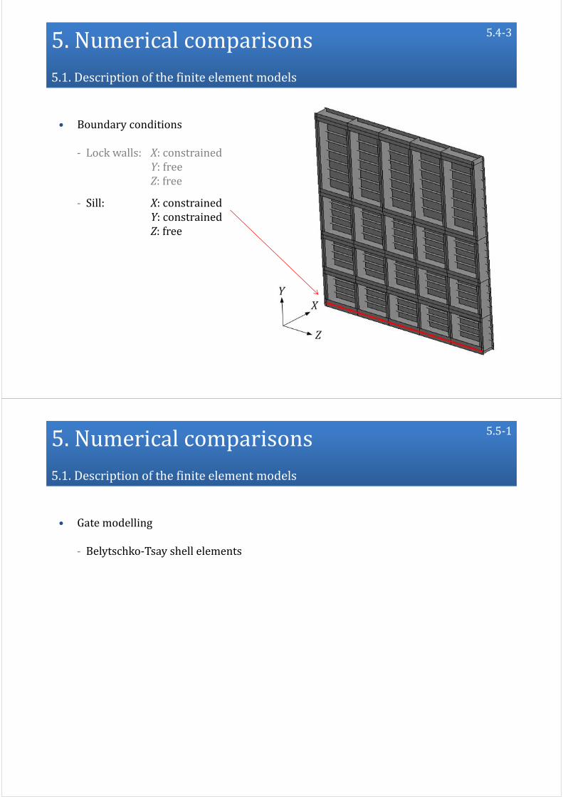
5.Numerical comparisons5.1.Descriptionofthefinite element models
• Boundary conditions
‐ Lock walls: X: constrainedY: freeZ: free
‐ Sill: X: constrainedY: constrainedZ: free
5.4‐3
5.Numerical comparisons5.1.Descriptionofthefinite element models
• Gate modelling
‐ Belytschko‐Tsay shell elements
5.5‐1

5.Numerical comparisons5.1.Descriptionofthefinite element models
• Gate modelling
‐ Belytschko‐Tsay shell elements
‐ Elastoplastic material:
MAT_PIECEWIESE_LINEAR_PLASTICITY
Parameters
E 210 000MPa
ET 10 180MPa
σ0 235MPa
ρ 7850kg/m3
ν 0.3
5.5‐2
5.Numerical comparisons5.1.Descriptionofthefinite element models
• Vessel modelling
‐ Belytschko‐Tsay shell elements
5.6‐1

5.Numerical comparisons5.1.Descriptionofthefinite element models
• Vessel modelling
‐ Belytschko‐Tsay shell elements
‐ Perfectly rigid material:
MAT_RIGID
5.6‐2
5.Numerical comparisons5.1.Descriptionofthefinite element models
• Vessel modelling
‐ Belytschko‐Tsay shell elements
‐ Perfectly rigid material
‐ Idealized parabolic bow shape
Parameters
p 3.5m
ET 7m
hb 8m
ϕ 70°
ψ 79°
5.6‐3

5.Numerical comparisons5.1.Descriptionofthefinite element models
• Vessel modelling
‐ Belytschko‐Tsay shell elements
‐ Perfectly rigid material
‐ Idealized parabolic bow shape
‐ Fictitious rigid boby:
PART_INERTIA
Parameters
M 4000t
V 2m/s
5.6‐4
5.Numerical comparisons5.1.Descriptionofthefinite element models
• Contact modelling
‐ LS‐DYNA standard penalty formulation:
CONTACT_AUTOMATIC_SURFACE_TO_SURFACE
Contact
5.7‐1

5.Numerical comparisons5.1.Descriptionofthefinite element models
• Contact modelling
‐ LS‐DYNA standard penalty formulation:
CONTACT_AUTOMATIC_SURFACE_TO_SURFACE
CONTACT_AUTOMATIC_GENERAL
Self‐contact
5.7‐2
5.Numerical comparisons5.1.Descriptionofthefinite element models
• Contact modelling
‐ LS‐DYNA standard penalty formulation
‐ Default values of the contact parameters
5.7‐3

5.Numerical comparisons5.1.Descriptionofthefinite element models
• Gate mesh (PATRAN)
‐ Regular rectangular elements
5.8‐1
5.Numerical comparisons5.1.Descriptionofthefinite element models
• Gate mesh (PATRAN)
‐ Regular rectangular elements
‐ Dimension ≤ ℓe in the impact area
5.8‐2

5.Numerical comparisons5.1.Descriptionofthefinite element models
• Gate mesh (PATRAN)
‐ Regular rectangular elements
‐ Dimension ≤ ℓe in the impact area
‐ Dimension ≤ ℓe at the boundaries
5.8‐3
5.Numerical comparisons5.1.Descriptionofthefinite element models
• Gate mesh (PATRAN)
‐ Regular rectangular elements
‐ Dimension ≤ ℓe in the impact area
‐ Dimension ≤ ℓe at the boundaries
‐ Dimension ≤ 2ℓe otherwise
5.8‐4

5.Numerical comparisons5.1.Descriptionofthefinite element models
• Gate mesh (PATRAN)
‐ Regular rectangular elements
‐ Dimension ≤ ℓe in the impact area
‐ Dimension ≤ ℓe at the boundaries
‐ Dimension ≤ 2ℓe otherwise
⟶ ℓe = 5 cm (mesh convergence)
5.8‐5
5.Numerical comparisons5.1.Descriptionofthefinite element models
• Vessel mesh (PATRAN)
‐ Dimension ∼ ℓe near the impact
‐ Coarser mesh otherwise
5.9

5.Numerical comparisons
5.1. Descriptionofthefinite element models
5.2. Example 1:gate supported byasill
5.3. Example 2:gate freeat thebottom
5.10
5.Numerical comparisons5.2.Example 1:gate supported byasill
• Example 1 (LS‐DYNA)
‐ Typical lock gate
‐ Supported by a sill
5.10‐1

5.Numerical comparisons5.2.Example 1:gate supported byasill
• Example 1 (LS‐DYNA)
Vessel:
M0 =4000t
V0 =2m/s
E0 =8MJ
5.10‐2
5.Numerical comparisons5.2.Example 1:gate supported byasill
0
2
4
6
8
10
12
0 0,3 0,6 0,9 1,2 1,5
Resistance(MN)
δ (m)
LS‐DYNA
Analytical
• Example 1: Resistance
5.10‐3

5.Numerical comparisons5.2.Example 1:gate supported byasill
• Example 1: Energy
0
1
2
3
4
5
6
7
8
9
0 0,3 0,6 0,9 1,2 1,5
Energy(MJ)
δ (m)
LS‐DYNA
Analytical
8%
5.10‐4
5.Numerical comparisons5.2.Example 1:gate supported byasill
• Example 1: Consistency
⟶ Ideally: experimental validation
5.11‐1
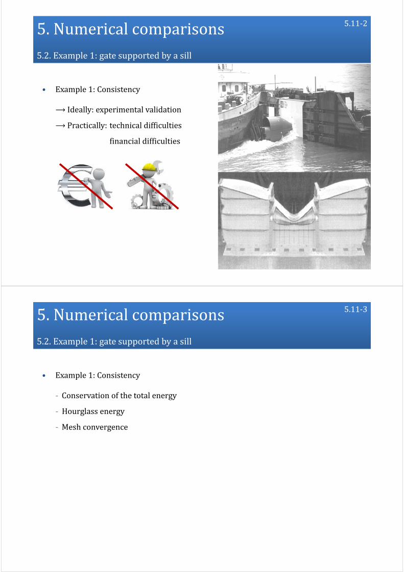
5.Numerical comparisons5.2.Example 1:gate supported byasill
• Example 1: Consistency
⟶ Ideally: experimental validation
⟶Practically:technical difficulties
financial difficulties
5.11‐2
5.Numerical comparisons5.2.Example 1:gate supported byasill
• Example 1: Consistency
‐ Conservation of the total energy
‐ Hourglass energy
‐ Mesh convergence
5.11‐3

5.Numerical comparisons5.2.Example 1:gate supported byasill
• Example 1: Consistency – Total energy
0
1
2
3
4
5
6
7
8
9
0 0,3 0,6 0,9 1,2 1,5
Energy(MJ)
δ (m)
Internal
Kinetic
Total
5.12
5.Numerical comparisons5.2.Example 1:gate supported byasill
• Example 1: Consistency – Hourglass energy
0
0,1
0,2
0,3
0,4
0,5
0,6
0 0,3 0,6 0,9 1,2 1,5
Ratio(%)
δ (m)
Hourglassratio
<5%
5.13

5.Numerical comparisons5.2.Example 1:gate supported byasill
• Example 1: Consistency – Mesh convergence illustration
0
2000
4000
6000
8000
10000
12000
14000
16000
0 0,5 1 1,5 2 2,5
Resistance(kN)
δ (m)
20cm
5.14‐1
5.Numerical comparisons5.2.Example 1:gate supported byasill
• Example 1: Consistency – Mesh convergence illustration
0
2000
4000
6000
8000
10000
12000
14000
16000
0 0,5 1 1,5 2 2,5
Resistance(kN)
δ (m)
20cm
10cm
0
2000
4000
6000
8000
10000
12000
14000
16000
0 0,5 1 1,5 2 2,5
Resistance(kN)
δ (m)
20cm
10cm
5.14‐2

5.Numerical comparisons5.2.Example 1:gate supported byasill
• Example 1: Consistency – Mesh convergence illustration
0
2000
4000
6000
8000
10000
12000
14000
16000
0 0,5 1 1,5 2 2,5
Resistance(kN)
δ (m)
20cm
10cm
7.5cm
5.14‐3
5.Numerical comparisons5.2.Example 1:gate supported byasill
• Example 1: Consistency – Mesh convergence illustration
0
2000
4000
6000
8000
10000
12000
14000
16000
0 0,5 1 1,5 2 2,5
Resistance(kN)
δ (m)
20cm
10cm
7.5cm
5cm
5.14‐4

5.Numerical comparisons5.2.Example 1:gate supported byasill
• Example 1: Consistency – Mesh convergence illustration
0
2000
4000
6000
8000
10000
12000
14000
16000
0 0,5 1 1,5 2 2,5
Resistance(kN)
δ (m)
20cm
10cm
7.5cm
5cm
4cm
⟶ℓe =5cm
5.14‐5
5.Numerical comparisons5.2.Example 1:gate supported byasill
• Example 1: Influence of failure
Plasticdeformation>εr
5.15‐1

5.Numerical comparisons5.2.Example 1:gate supported byasill
• Example 1: Influence of failure
Element thickness/lengthratio
5.15‐2
5.Numerical comparisons5.2.Example 1:gate supported byasill
• Example 1: Influence of failure
0
2
4
6
8
10
12
0 0,3 0,6 0,9 1,2 1,5
Resistance(MN)
δ (m)
LS‐DYNA
Analytical
Withfailure
5.15‐3
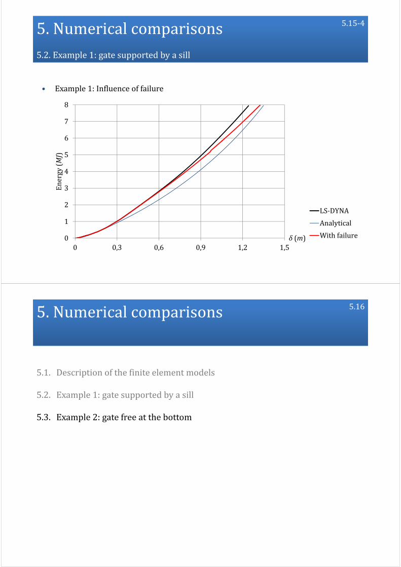
5.Numerical comparisons5.2.Example 1:gate supported byasill
• Example 1: Influence of failure
0
1
2
3
4
5
6
7
8
0 0,3 0,6 0,9 1,2 1,5
Energy(MJ)
δ (m)
LS‐DYNA
Analytical
Withfailure
5.15‐4
5.Numerical comparisons
5.1. Descriptionofthefinite element models
5.2. Example 1:gate supported byasill
5.3. Example 2:gate freeat thebottom
5.16

5.Numerical comparisons5.2.Example 2:gate freeat thebottom
• Example 2 (LS‐DYNA)
‐ Typical lock gate
‐ Not supported by a sill
5.16‐11
5.Numerical comparisons5.2.Example 2:gate freeat thebottom
• Example 2 (LS‐DYNA)
Vessel:
M0 =4000t
V0 =2m/s
E0 =8MJ
5.16‐2

5.Numerical comparisons5.2.Example 2:gate freeat thebottom
• Example 2 (LS‐DYNA)
5.16‐3
5.Numerical comparisons5.2.Example 2:gate freeat thebottom
• Example 2: Resistance
0
1
2
3
4
5
6
7
0 0,3 0,6 0,9 1,2 1,5 1,8
Resistance(MN)
δ (m)
LS‐DYNA
Analytical
Collapse
5.16‐4

5.Numerical comparisons5.2.Example 2:gate freeat thebottom
• Example 2: Energy
0
1
2
3
4
5
6
7
8
9
0 0,3 0,6 0,9 1,2 1,5 1,8
Energy(MN)
δ (m)
LS‐DYNA
Analytical
10%
5.16‐5
1.Introduction
2.Generalbackground
3.Required data
4.Analytical derivation
5.Numerical comparisons
6.Extensiontomitrelock gates
7.Conclusions
6.1
Presentation ofnewanalytical methods toassess thecrashworthiness oflock gates

6.EXTENSIONTOMITRELOCKGATES
6.1. Analytical modifications
6.2. Numerical comparisons
6.2
6.EXTENSIONTOMITRELOCKGATES
6.1. Analytical modifications
6.2. Numerical comparisons
6.2

6.EXTENSIONTOMITRELOCKGATES6.1.Analytical modifications
• Up to now:
6.3
‐ Plane lock gate
‐ Single plating
‐ Orthogonal reinforcement
Example:liftinglock gate ofMeinderich(Rhine‐Hernecanal,Germany)
6.EXTENSIONTOMITRELOCKGATES6.1.Analytical modifications
• Extension:
6.4‐1
‐ Mitre lock gate
‐ Single plating
‐ Orthogonal reinforcement

6.EXTENSIONTOMITRELOCKGATES6.1.Analytical modifications
• Extension:
6.4‐2
‐ Mitre lock gate
‐ Single plating
‐ Orthogonal reinforcement
Mitreangleβ
6.EXTENSIONTOMITRELOCKGATES6.1.Analytical modifications
• Derivation of the local resistance
‐ SE1: Plating
‐ SE2: Horizontal girders and vertical frames
‐ SE3: Intersections
6.5

6.EXTENSIONTOMITRELOCKGATES6.1.Analytical modifications
• Derivation of the local resistance
⟶ Analytical derivation…
SE1 SE2– Vertical SE2– Horizontal
6.6‐1
6.EXTENSIONTOMITRELOCKGATES6.1.Analytical modifications
• Derivation of the local resistance
⟶ Analytical derivation…
…withdueconsiderationforβ
6.6‐2

6.EXTENSIONTOMITRELOCKGATES6.1.Analytical modifications
• Derivation of the local resistance
⟶ Analytical derivation…
…withdueconsiderationforβ
…consistentwithplanegatesifβ→0
6.6‐3
6.EXTENSIONTOMITRELOCKGATES6.1.Analytical modifications
• Derivation of the global resistance
‐ Set of horizontal beams
6.7‐1

6.EXTENSIONTOMITRELOCKGATES6.1.Analytical modifications
• Derivation of the global resistance
‐ Set of horizontal beams
‐ Connected by the frames
6.7‐2
6.EXTENSIONTOMITRELOCKGATES6.1.Analytical modifications
• Derivation of the global resistance
‐ Set of horizontal beams
‐ Connected by the frames
‐ Global out‐of‐plane displacement
6.7‐3
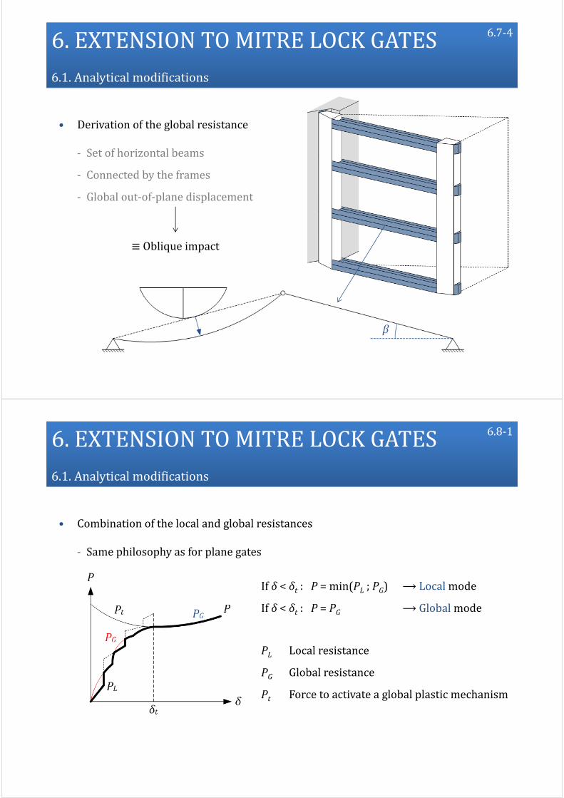
6.EXTENSIONTOMITRELOCKGATES6.1.Analytical modifications
• Derivation of the global resistance
‐ Set of horizontal beams
‐ Connected by the frames
‐ Global out‐of‐plane displacement
≡Obliqueimpact
6.7‐4
6.EXTENSIONTOMITRELOCKGATES6.1.Analytical modifications
• Combination of the local and global resistances
‐ Same philosophy as for plane gates
6.8‐1
If δ < δt : P = min(PL ; PG) ⟶ Local mode
If δ < δt : P = PG ⟶Global mode
PL Localresistance
PG Globalresistance
Pt Forcetoactivate aglobalplasticmechanism
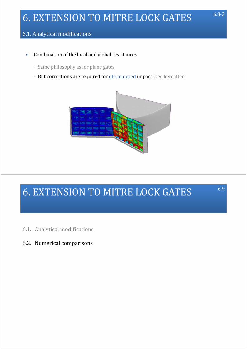
6.EXTENSIONTOMITRELOCKGATES6.1.Analytical modifications
• Combination of the local and global resistances
‐ Same philosophy as for plane gates
‐ But corrections are required for off‐centered impact (see hereafter)
6.8‐2
6.EXTENSIONTOMITRELOCKGATES
6.1. Analytical modifications
6.2. Numerical comparisons
6.9

6.EXTENSIONTOMITRELOCKGATES6.2.Numerical comparisons
• Results: off‐centered impact M0 = 4000 t ; V0 = 2m/s ; E0 = 8MJ
(Pre‐loading:hydrodstatic pressure)
6.10‐1
6.EXTENSIONTOMITRELOCKGATES6.2.Numerical comparisons
(Pre‐loading:hydrodstatic pressure)
• Results: off‐centered impact M0 = 4000 t ; V0 = 2m/s ; E0 = 8MJ
6.10‐2

6.EXTENSIONTOMITRELOCKGATES6.2.Numerical comparisons
• Results: off‐centered impact
Progressivelossofcontact
6.10‐3
6.EXTENSIONTOMITRELOCKGATES6.2.Numerical comparisons
• Results: off‐centered impact
Coulombslidingcriteria
LS‐DYNA:frictioncoefficientof0.3
Progressivelossofcontact
6.10‐4

6.EXTENSIONTOMITRELOCKGATES6.2.Numerical comparisons
• Results: off‐centered impact
0
1500
3000
4500
6000
7500
0 0,2 0,4 0,6 0,8 1 1,2
Resistance(kN)
δ (m)
Analyticalsolution Numericalsolution
Progressivelossofcontact
6.10‐5
6.EXTENSIONTOMITRELOCKGATES6.2.Numerical comparisons
• Results: off‐centered impact
Impossibletodissipatetheentireinitialkineticenergy
Progressivelossofcontact
6.10‐6

6.EXTENSIONTOMITRELOCKGATES6.2.Numerical comparisons
• Results: off‐centered impact
0
1
2
3
4
5
6
0 0,2 0,4 0,6 0,8 1 1,2
Energy(MJ)
δ (m)
Analyticalsolution Numericalsolution
∼60%ofE0
6.10‐7
6.EXTENSIONTOMITRELOCKGATES6.2.Numerical comparisons
• Results: centered impact M0 = 4000 t ; V0 = 2m/s ; E0 = 8MJ
6.11‐1

6.EXTENSIONTOMITRELOCKGATES6.2.Numerical comparisons
0
2000
4000
6000
8000
10000
12000
14000
16000
0 0,1 0,2 0,3 0,4 0,5 0,6 0,7 0,8 0,9
Resistance(kN)
δ (m)
Analyticalsolution Numericalsolution
• Results: centered impact
6.11‐2
6.EXTENSIONTOMITRELOCKGATES6.2.Numerical comparisons
0
1
2
3
4
5
6
7
8
9
0 0,1 0,2 0,3 0,4 0,5 0,6 0,7 0,8 0,9
Energy(MJ)
δ (m)
Analyticalsolution Numericalsolution
• Results: centered impact
100%ofE0
6.11‐3

6.EXTENSIONTOMITRELOCKGATES6.2.Numerical comparisons
0
1
2
3
4
5
6
7
8
9
0 0,1 0,2 0,3 0,4 0,5 0,6 0,7 0,8 0,9
Energy(MJ)
δ (m)
Analyticalsolution Numericalsolution
• Results: centered impact2%
6.11‐4
1.Introduction
2.Generalbackground
3.Required data
4.Analytical derivation
5.Numerical comparisons
6.Extensiontomitrelock gates
7.Conclusions
7.1
Presentation ofnewanalytical methods toassess thecrashworthiness oflock gates

7.CONCLUSIONS
7.1.Applicability
7.2.Limitationsandperspectives
7.2
7.CONCLUSIONS
7.1.Applicability
7.2.Limitationsandperspectives
7.2

7.CONCLUSIONS7.1.Applicability
• Different collision scenarios
‐ Plane lock gates
7.3‐1
7.CONCLUSIONS7.1.Applicability
• Different collision scenarios
‐ Plane lock gates
‐ Mitre lock gates
7.3‐2

7.CONCLUSIONS7.1.Applicability
• Different collision scenarios
‐ Plane lock gates
‐ Mitre lock gates
‐ Raked bow
7.3‐3
7.CONCLUSIONS7.1.Applicability
• Different collision scenarios
‐ Plane lock gates
‐ Mitre lock gates
‐ Raked bow
‐ Bulbous bow
7.3‐4

7.CONCLUSIONS7.1.Applicability
• Different collision scenarios
• Application to new lock gates
‐ Pre‐design: Optimization
7.4‐1
7.CONCLUSIONS7.1.Applicability
FEM
7.4‐2
• Different collision scenarios
• Application to new lock gates
‐ Pre‐design: Optimization
‐ Final design: Worst scenarios

7.CONCLUSIONS7.1.Applicability
7.4‐3
• Different collision scenarios
• Application to new lock gates
‐ Pre‐design: Optimization
‐ Final design: Worst scenarios
⟶ Aid for designers
7.CONCLUSIONS7.1.Applicability
7.4‐4
• Different collision scenarios
• Application to new lock gates
• Application to existing lock gates
‐ Rapid strength assessment

7.CONCLUSIONS7.1.Applicability
7.4‐5
• Different collision scenarios
• Application to new lock gates
• Application to existing lock gates
‐ Rapid strength assessment
‐ Protection devices
7.CONCLUSIONS7.1.Applicability
7.4‐6
• Different collision scenarios
• Application to new lock gates
• Application to existing lock gates
‐ Rapid strength assessment
‐ Protection devices
⟶ Aid for authorities

7.CONCLUSIONS
7.1.Applicability
7.2.Limitationsandperspectives
7.7
7.CONCLUSIONS7.2.Limitationsandperspectives
• Limitations due to the analytical method
‐ No local field (σ, ε…)
7.8‐1

7.CONCLUSIONS7.2.Limitationsandperspectives
• Limitations due to the analytical method
‐ No local field (σ, ε…)
‐ Rupture: Numerical treatment of rupture is not always reliable
Approximate analytical treatment of rupture is possible
Difficult to account for various rupture modes
7.8‐2
7.CONCLUSIONS7.2.Limitationsandperspectives
• Perspectives of analytical methods
‐ Other gate types: Double‐side gates
7.8‐.3

7.CONCLUSIONS7.2.Limitationsandperspectives
• Perspectives of analytical methods
‐ Other gate types: Double‐side gates
Sector gates
7.8‐4
7.CONCLUSIONS7.2.Limitationsandperspectives
• Perspectives of analytical methods
‐ Other gate types: Double‐side gates
Sector gates
‐ Other vessels: Barges
7.8‐5

7.CONCLUSIONS7.2.Limitationsandperspectives
• Perspectives of analytical methods
‐ Other gate types: Double‐side gates
Sector gates
‐ Other vessels: Barges
Other types
7.8‐6
7.CONCLUSIONS7.2.Limitationsandperspectives
• Perspectives of analytical methods
‐ Other gate types: Double‐side gates
Sector gates
‐ Other vessels: Barges
Other types
‐ Other structures: OWT jackets
7.8‐7

7.CONCLUSIONS7.2.Limitationsandperspectives
• Perspectives of analytical methods
‐ Other gate types: Double‐side gates
Sector gates
‐ Other vessels: Barges
Other types
‐ Other structures: OWT jackets
OWTmonopiles
7.8‐8
7.CONCLUSIONS7.2.Limitationsandperspectives
• Perspectives of analytical methods
‐ Other gate types: Double‐side gates
Sector gates
‐ Other vessels: Barges
Other types
‐ Other structures: OWT jackets
OWTmonopiles
7.8‐9
Underdevelopment
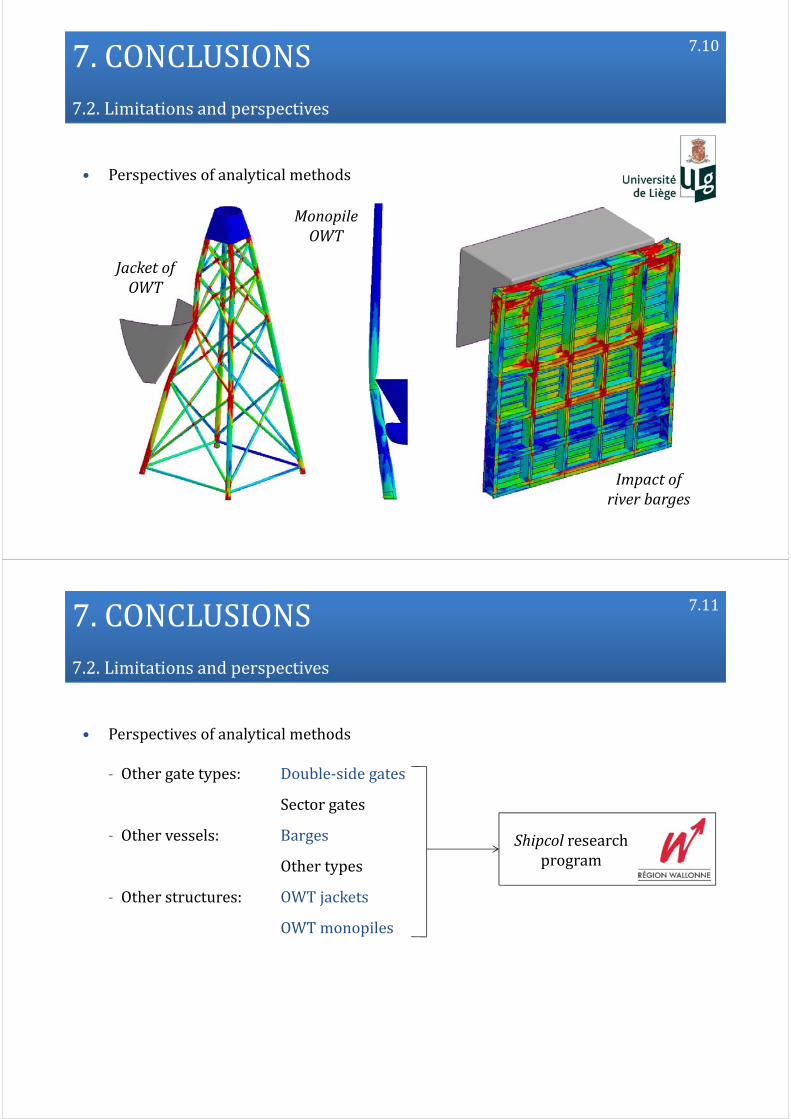
7.CONCLUSIONS7.2.Limitationsandperspectives
• Perspectives of analytical methods
7.10
JacketofOWT
MonopileOWT
Impactofriverbarges
7.CONCLUSIONS7.2.Limitationsandperspectives
• Perspectives of analytical methods
‐ Other gate types: Double‐side gates
Sector gates
‐ Other vessels: Barges
Other types
‐ Other structures: OWT jackets
OWTmonopiles
7.11
Shipcol researchprogram

7.CONCLUSIONS
• Acknowledgements
7.12
Government oftheWalloon Region ofBelgium
Financial contribution to the research projectShipcol on vessel collisions against lock gatesand offshore wind turbines.
MSCSoftwareCorporation
Technical support to the use of the softwarePatran and Nastran to create numerical modelsand perform finite element analyses.
7.CONCLUSIONS 7.13