design of lobe pair profile of an external rotary lobe · pdf file2nd international and 17th...
TRANSCRIPT
2nd International and 17th National Conference on Machines and Mechanisms iNaCoMM2015-032
________________ 1A D Patel Institute of Technology (ADIT), New V. V. Nagar-388121, [email protected] 2 Department of Mechanical Engineering, ADIT, New V. V. Nagar-388121, [email protected] 3 Department of Mechanical Engineering, ADIT, New V. V. Nagar-388121, [email protected]
1
Design of lobe pair profile of an external rotary lobe
pump
Tanuja P. Mishra1, Yashavant D. Patel2, Unnati A. Joshi3
Abstract
Noncircular lobe rotor pair profile generation is complex and new form of
external rotary lobe pump used in industry. Rotors used in lobe pumps are conjugate
generated pair, generated from their respective pitch pairs. The pumping ratio of a
lobe pump is also a function of pure geometry of the lobe and thus it is mainly
governed by the pitch and deviation function. In present work, non-circularity of the
pitch was considered as a main parameter. Direct Profile Design (DPD) method was
used to develop identical noncircular pitch pair. The noncircular pitch pair was
modified to get generated pair by applying envelope theory and deviation function
method. Lobe pair with different noncircular pitch functions was obtained for a
given deviation function. The zero interference of the generated conjugate lobe pair
at different orientations was also verified using high end software. Specific flowrate
formula in the form of pitch function and deviation function was used to compare
performance of the lobe profiles developed using different noncircular pitch
functions.
Keywords: Noncircular pitch, Envelope theory, Deviation function, Direct profile
design.
1 Introduction
Lobe rotor pair is used as a crucial component in many mechanical systems like
blowers, compressors and pumps. Positive displacement of fluid occurs as the two
rotors are in conjugate motion as shown in the Fig. (1). The two rotors are attached
with a pair of driving and driven gear for continuous motion; reason being one rotor
can drive the other rotor only for half cycle. The lobe rotor pair which is identical to
a gear pair is a conjugate kinematic pairs with continuous motion without oscillation.
It maintains same velocity at each point of their contact. Conjugate pairs are of two
types, pitch pair and generated pair. Pitch pairs are used to evolve their respective
generated pairs.
In 1998, Tong have developed an algorithm for generating identical noncircular pitch
pairs of any order known as DPD method [1]. In 1999, Deviation Function method
was developed by Tong and Yang [2] for generated profile from the existing pitch
curve using envelope theory. In 1999, Tong had also carried out the flow rate
analysis of a lobe pump by taking pumping ratio of lobe pump as the performance
index. Pitch non-circularity and lobe non-circularity are introduced as two
dimensionless parameters along with their design significance by Tong [3].
Generalized specific flow rate formula in terms of pitch and deviation function was
derived by Yang in 2002 [4]. In 2005, Tong and yang designed a lobe pair with
deviation function based on the flowrate requirement for circular pitch [5]. Deviation
function was also used by Yang Shyue-Cheng to modify an elastic conjugate element
used in rotary gear pump to decrease stresses involved and increasing its bending

2nd International and 17th National Conference on Machines and Mechanisms iNaCoMM2015-032
2
strength [6]. Sarah Warren used deviation function method to design a rotary engine
and an apex seal profile thereby proving the versatility of this method [7]. Pitch non-
circularity and lobe non-circularity are the dimensionless parameters which governs
lobe slenderness near tips of lobe and centre of lobe respectively. In 2002, Yang
derived specific flowrate formula in terms of pitch and deviation function and
compared the flowrate for different values of lobe non-circularity by taking a circular
pitch [4]. Hence, change in flowrate with change in lobe non-circularity was
concluded. In the present paper, noncircular pitch is considered and for a given
deviation function, variation in flowrate with different noncircular pitch functions is
observed.
Figure 1:Lobe Pump
2 Direct-Profile-Design Method
A lobe rotor is designed in two steps in form of pitch pair design followed by
generated pair. Correct pitch profile will cause uniform rolling action of the pitch
pair. The conjugate pitch pair always makes a contact at a point where they share the
same velocity. The DPD method was developed by S.H. Tong [1] for the generation
of identical noncircular pitch pair.
Assume that rotor 1 and 2 as shown in Fig. (2) are two identical noncircular pitch
pairs with a radius 𝑟1(𝜃1) and 𝑟2(𝜃2)respectively with monotonically increasing and
C1 continuity. Point A1 is the starting point of the function 𝑟1(𝜃1). The profile in the
second quadrant of pitch 1 is divided into two segments i.e. segment A1E1and
segment D1E1.
Figure 2: Noncircular Pitch Pair [1]
Segment D1E1 is same as segment D2C2 on rotor 2. Pitch pair is a kinematical,
conjugate pair and thus profile segment A1B1on rotor 1 should be conjugate with the
profile segment D2C2on rotor 2, i.e.
𝑟2𝜃1 = 𝑙 − 𝑟1(𝜃1) (1)
θ1 and θ2 is the angular position of rotors on rotor 1 and 2 respectively. To ensure
pure rolling condition, both the pitch should have the same velocity at the contact

2nd International and 17th National Conference on Machines and Mechanisms iNaCoMM2015-032
3
point, i.e. 𝑟1𝑑𝜃1 = 𝑟2𝑑𝜃2. Thus, conjugacy and pure rolling are the two basic
conditions need to be satisfied by all pitch functions. Combining the above two
conditions relation between 𝜃1 and 𝜃2 can be given as
𝜃2 = ∫𝑟1
𝑙 − 𝑟1𝑑𝜃1
(2)
At point E1, where 𝑟1(𝜃1) = 𝑙/2 (i.e. 𝑟1 = 𝑟2 = 𝑙/2) point B1 and C2 meets. At
this point, 𝜃1 becomes ∅1 and ∅1 + ∅2 = 𝜋/2. Similarly profile segment in second
quadrant of pitch 1 is composed of two segments as shown in Fig 2. These segments
are given by,
𝑟1(𝜃1) = segment A1B1 = 𝑓(𝜃1), when 0 ≤ 𝜃1 ≤ ∅1 (3)
𝑟1(𝜃1) = segment C1D1 =segment C2D2, when ∅1 ≤ 𝜃1 ≤ 𝜋/2 (4)
3 Deviation Function Method
“Deviation Function (DF)” method was developed by Tong and Yang [2] for
generating a conjugate profile from a given pitch profile. Generated lobe pair is not a
pure rolling pair as pitch pair. Sliding occurs during the meshing of two lobes due to
deviation between contact point of pitch pair P and contact point of generated pair G.
In deviation function method, a function is selected as a pattern of deviation for
different angular position. The generated lobe pair is absolute summation of pitch
radius and deviation at respective angular position. Let p1 and p2, represented by thin
lines is a pair of original noncircular pitches; and g1 and g2, represented by bold lines
are corresponding generated profiles as shown in Fig. (3). The pitch pairs shown are
identical and noncircular. At a given instance, the contact point of rotor’s pitch pair
p1 and p2 is at point P. The locus of point P in moving coordinate frame O1xy forms
the pitch profile 𝑟1(𝜃1).
Figure 3: Pitch Pair and Generated Pair using Deviation Function method [2]
Similarly, let G be the contact point of the two generated profiles g1 and g2
corresponding to the same instant as that of pitch contact point P (here generated
profilesg1 and g2 are considered to be as welded to pitch profiles p1 and p2,
respectively). The locus of point G in the moving coordinate frame O1xy gives the
generated profile. Thus, the deviation function method designs G(θ1) by offsetting
P(θ1) by a distance equal to e(θ1) as shown in Fig. (3). This offset distance is called
deviation and its representation in form of angular position is called as deviation-
function e(θ1) . 𝑒(𝜃1) = 𝑃(𝜃1) − 𝐺(𝜃1) in 0 ≤ 𝜃1 ≤ ∅1 (5)
where, 𝑒(𝜃1)is called the “deviation function”.
2nd International and 17th National Conference on Machines and Mechanisms iNaCoMM2015-032
4
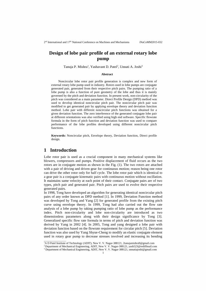
3.1 The Envelope Theory
The generated profile is the envelope of the family of the generating circles S on the
O1xy frame. The resultant envelope profile is the envelope generated by the circles
with radius equal to e and centre as a point on pitch profile. The family of the
generating circles S on the O1xy frame is obtained by applying envelope theory as
shown in Fig. (4). Point P is the contact point of two pitch curves and G is the
contact point of generated curves (circles) S.
Figure 4: Generating circle (S) with radius (e)
The family of curve is described by the equation in form F(x, y, d) = 0. According to
the envelope theory of second type, F should be differentiated with respect to 𝑑.
Eliminating d and reducing equation in form of x and y gives the equation of the
envelope. Here, the family of curve is a family of generating circles S. The equation
of family of circle is given by,
𝑆(𝑔𝑥 , 𝑔𝑦 , 𝜃1) = (𝑔𝑥 − 𝑟1 𝑐𝑜𝑠 𝜃1)2 + (𝑔𝑦 − 𝑟1 𝑠𝑖𝑛 𝜃1)
2 − 𝑒2 = 0 (6)
The envelope of generating circle is given by, 𝜕𝑆1
𝜕𝜃1⁄ = 0
(7)
The desired envelope profile is obtained by solving the two equations, Eq. (6) and
(7) simultaneously [7]. The alternate method to represent the family of curve is by
taking each parameter in parametric form. Thus, describing parametric equations of
same circle as in Eq. (6) and takingψ1 as parameter,
(𝑔𝑥 − 𝑟1 𝑐𝑜𝑠 𝜃1) = 𝑒 𝑐𝑜𝑠 𝜓1 and (𝑔𝑦 − 𝑟1 𝑠𝑖𝑛 𝜃1) = 𝑒 𝑠𝑖𝑛 𝜓1
𝑔𝑥 = 𝑟1𝑐𝑜𝑠𝜃1 + 𝑒𝑐𝑜𝑠𝜓1 (8)
𝑔𝑦 = 𝑟1𝑠𝑖𝑛𝜃1 + 𝑒𝑠𝑖𝑛 𝜓1 (9)
A point (𝑔𝑥, 𝑔𝑦) is on the envelope curve only when,
||
𝜕𝑔𝑥𝜕𝜓1
𝜕𝑔𝑥𝜕𝜃1
𝜕𝑔𝑦
𝜕𝜓1
𝜕𝑔𝑦
𝜕𝜃1
|| = 0
(10)
Simplifying,
r1′ + r1 tan(ψ1– θ1) = −e
′√1 + tan2(ψ1– θ1) (11)

2nd International and 17th National Conference on Machines and Mechanisms iNaCoMM2015-032
5
Squaring and rearranging terms, a quadratic equation in terms of tan(ψ1 − θ1) is
finally represented as,
ψ1= θ1 + tan
−1
(
−r1r1
′ ± e′√r12 + r1
′ 2 − e′2
r12 − e′2
)
(12)
Deviation function 𝑒(𝜃1) is provided in the range 0 ≤ θ1 ≤ ∅1 and the deviation
function has to be zero at the conjunction point for ensuring C' continuity [2] (where
θ1 =∅1), i.e.
𝑒(𝜙1)=0 (13)
A deviation function 𝑒(𝜃1) is satisfying Eq. (13) with many possibilities. Few
possibilities satisfying the above conditions reported in [2] are as under:
𝑒(𝜃1) = (𝜙1 − 𝜃1)𝑓1(𝜃1) (14a)
𝑒(𝜃1) = 𝑠𝑖𝑛(𝜙1 − 𝜃1)𝑓2(𝜃1) (14b)
𝑒(𝜃1) = (𝑒(𝜙1−𝜃1) − 1)𝑓3(𝜃1) (14c)
4 Concept of flowrate
Flowrate of pump is analysed using its dependent parameters. Let B denote the
pocket area and A denotes the rotor area as per Fig. (1). The pocket area marked with
hatched lines and it is an area between the housing and lobes where the fluid is
normally trapped. Let 𝑞𝑖 be the initial delivery volume per rotor revolution. If there
is no leakage during the operation then 𝑞𝑖 is expressed as,
𝑞𝑖 = 2(𝜋𝑏2 − 𝐴)𝑤 (15)
Where, b is maximum radial length, A is area and w = thickness of rotor.
The pump size V can be expressed as,
𝑉 = (𝜋𝑏2 + 2𝑏𝑙)𝑤 (16)
The pumping ratio is the ratio of delivery volume to total volume. Thus, pumping
ratio rp is obtained using Eq. (15) and (16),
𝑟𝑝 =𝑞𝑖𝑉=2(𝜋𝑏2 − 𝐴)
(𝜋𝑏2 + 2𝑏𝑙)
(17)
It is observed that the pumping ratio is dependent on the flowrate and total volume
which depends only on the geometry of rotor. Rotor’s geometry is a function of both
rotor's pitch and deviation functions [3]. Therefore, it is reasonable to suggest that
following actions can be taken to improve pumping ratios:
a. Changing the pitch function: Usually, the pitch curve is always a circle. Pitch
curve with different noncircular functions responds in terms of geometrical
changes and ultimately variation in flowrate.
b. Changing the deviation function: Different deviation function satisfying Eq. (13)
can be selected keeping the pitch function constant to observe variation in
flowrate with change in deviation function.
c. Different combinations of pitch function and deviation functions.
4.1 Specific Flowrate
The flowrate of a lobe pump is a function of angular position and varies periodically.
During the meshing of the two lobes, the position of contact point change which
leads to change in magnitude of flowrate. Pumping flowrate becomes a major

2nd International and 17th National Conference on Machines and Mechanisms iNaCoMM2015-032
6
criterion to judge lobe pump performance after its design. Flowrate of a lobe pump
can be defined as “delivery volume of pumping fluid per unit time”. In 2002 Yang
derived the specific flowrate formula in terms of pitch and deviation function. This
specific flowrate is a dimensionless parameter given by, 𝑓 = 𝐹/𝑛𝑉 where 𝑛 is real
lobe frequency and 𝑉 is pump size. The specific flowrate formula in terms of pitch
and deviation function is given as
𝑓 =𝜋𝑙(𝑏2 − 𝑟1(𝑙 − 𝑟1) − 𝑒
2)
(𝑙 − 𝑟1)(𝜋𝑏2 + 2𝑏𝑙)
(18)
5 Flowrate analysis of Lobe Profile
Flowrate analysis of the lobe pump with circular as well as non-circular pitch
function is carried out in this section. All the pitch profiles are generated using DPD
method as discussed earlier for same centre to centre distance between lobes. The
developed pitch profile was modified to generated profile using deviation function
method. Daniel C.H. Yang et. al [4] reported the flowrate analysis of lobe profile
generated using different deviation function method. They reported effect of lobe
non-circularity and number of lobes on the specific flowrate. However, the analysed
profiles were all made using a circular pitch. The effect on specific flowrate of the
lobe profiles with change in pitch function is discussed in subsequent section using
the Eq. (18).
5.1 Flowrate analysis of lobe pump with circular pitch
5.1.1 Generation of Circular Pitch Pair Profile
Presently, lobe rotor pair in lobe pumps with circular pitch profiles is commonly
used in industries. A pitch pair with circular pitch having radius of lobe 1 and lobe 2
are as 𝑟1 = 𝑟2 = 1 as shown in Fig. (5). 𝑂1𝑂2is the common normal to pitch profile
at point A for a particular velocity ratio.
Figure 5: Circular Pitch Pair
5.1.2 Generation of lobe pair using deviation function method
Let the deviation function is an arbitrary pick 𝑒(𝜃1) = (𝜙1 − 𝜃1)(𝑐0 + 𝑐1𝜃1) having
∅ = 45° for 𝑓1(𝜃1) = 𝑐0 + 𝑐1𝜃1 where 𝑐0 and 𝑐1 are coefficients which governs the
geometry of rotor. The coefficient 𝑐0 governs width of the rotor at its central portion.
Let value of 𝑐0 be 𝑙/(9𝜙1) and 𝑐1 = 𝑙/(9∅12). Results shows that larger the value of
𝑐0 more slender will be the rotor. The rotor with smaller 𝑐1 is sharper at tips than the
rotor with larger value of 𝑐1. The small circle on periphery of pitch circles are the
generating circles as shown in Fig. (6). These circles are used to modify pitch circle
to generated profile.
2nd International and 17th National Conference on Machines and Mechanisms iNaCoMM2015-032
7
Inputs:
1. Pitch function, 𝑟1(𝜃1) =𝑙/2, where 𝑎 = 𝑏 = 7, ∅1 = 45ᵒ, 𝑟2(𝜃1) = 𝑙 − 𝑟1(𝜃1),
𝜃2 = ∫𝑟1
𝑙 − 𝑟1𝑑𝜃1
2. Deviation function, 𝑒(𝜃1) = (𝜙1 − 𝜃1) (𝑙
9∅1+
𝑙
9∅12 θ1), 0 ≤ 𝜃1 ≤ ∅1
𝑒(𝜃1) = ‖𝑃(𝜃1) − 𝐺(𝜃1)‖, for 0 ≤ θ1 ≤ ∅1
3. Value of 𝑟1 and 𝑒 in Eq. (18) for specific flowrate
Output: Generated profile and specific flowrate
Figure 6(a): Generated profile using
Circular Pitch function
Figure 6(b):Flowrate of Generated
profile in (a)
5.2 Flowrate analysis of lobe pump with linear pitch
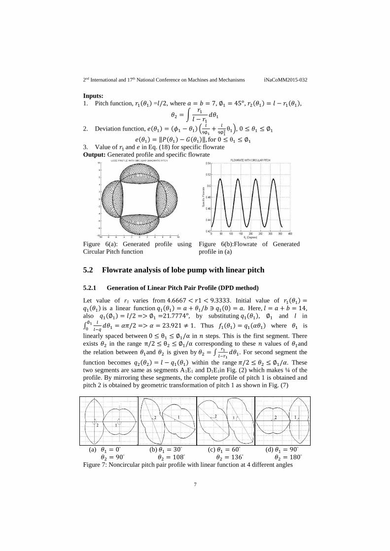
5.2.1 Generation of Linear Pitch Pair Profile (DPD method)
Let value of r1 varies from 4.6667 < 𝑟1 < 9.3333. Initial value of 𝑟1(𝜃1) =𝑞1(𝜃1) is a linear function 𝑞1(𝜃1) = 𝑎 + 𝜃1/𝑏 ∋ 𝑞1(0) = 𝑎. Here, 𝑙 = 𝑎 + 𝑏 = 14,
also 𝑞1(∅1) = 𝑙/2 => ∅1 =21.7774ᵒ, by substituting 𝑞1(𝜃1), ∅1 and l in
∫𝑙
𝑙−𝑞𝑑𝜃1 = 𝛼𝜋/2
∅10
=> 𝛼 = 23.921 ≠ 1. Thus 𝑓1(𝜃1) = 𝑞1(𝛼𝜃1) where 𝜃1 is
linearly spaced between 0 ≤ θ1 ≤ ∅1/α in 𝑛 steps. This is the first segment. There
exists 𝜃2 in the range π/2 ≤ θ2 ≤ ∅1/α corresponding to these 𝑛 values of 𝜃1and
the relation between 𝜃1and 𝜃2 is given by 𝜃2 = ∫𝑟1
𝑙−𝑟1𝑑𝜃1. For second segment the
function becomes 𝑞2(𝜃2) = 𝑙 − 𝑞1(𝜃1) within the range 𝜋/2 ≤ 𝜃2 ≤ ∅1/𝛼. These
two segments are same as segments A1E1 and D1E1in Fig. (2) which makes ¼ of the
profile. By mirroring these segments, the complete profile of pitch 1 is obtained and
pitch 2 is obtained by geometric transformation of pitch 1 as shown in Fig. (7)
(a) 𝜃1 = 0
ᵒ
𝜃2 = 90ᵒ
(b) 𝜃1 = 30ᵒ
𝜃2 = 108ᵒ
(c) 𝜃1 = 60ᵒ
𝜃2 = 136ᵒ
(d) 𝜃1 = 90ᵒ
𝜃2 = 180ᵒ
Figure 7: Noncircular pitch pair profile with linear function at 4 different angles

2nd International and 17th National Conference on Machines and Mechanisms iNaCoMM2015-032
8
5.2.2 Generation of lobe pair using deviation function method
A noncircular pitch with linear function as obtained in Sec. 5.2.1 is modified to
generated profile using the same deviation function used to modify the circular pitch.
The pitch with linear function is generated using DPD method as shown in Fig.
(8(a)).
Inputs:
1. Pitch function, 𝑟1(𝜃1) = 𝑎 + 𝜃1/𝑏, where 𝑎 = 4.667, 𝑏 = 9.333,∅1 = 52.162ᵒ,
2. Deviation function, 𝑒(𝜃1) = (𝜙1 − 𝜃1) (𝑙
9∅1+
𝑙
9∅12 θ1), 0 ≤ 𝜃1 ≤ ∅1
3. Value of pitch and deviation function in Eq. (18)
Output: Generated lobe profile (Fig. (8(a))) and specific flowrate (Fig. (8(b))).
Figure 8(a): Generated profile using linear
pitch function
Figure 8(b): Flowrate of generated
profile
5.3 Flowrate analysis of lobe pump with quadratic pitch
5.3.1 Quadratic Pitch Pair Profile Generation
Let a = 4, b = 10, 𝑙 = 14 and the initial design for the pitch function is 𝑞1(𝜃1) =
𝑟1(𝜃1) =𝑙3⁄ + 0.1834𝑙𝜃1
2 where, ∅1 = 54.6194.
(a) 𝜃1 = 0
ᵒ
𝜃2 = 90ᵒ
(b) 𝜃1 = 30ᵒ
𝜃2 = 105ᵒ
(c) 𝜃1 = 60ᵒ
𝜃2 = 120ᵒ
(d) 𝜃1 = 90ᵒ
𝜃2 = 180ᵒ
Figure 9: Noncircular pitch profile with quadratic pitch function at 4 different angles
5.3.2 Generation of lobe pair using deviation function method
The noncircular quadratic pitch profile used to generate the lobe profile is discussed
in Section 5.3.1.
Inputs:
1. Pitch function, 𝑟1(𝜃1) = 𝑙/3 + 0.1834𝑙𝜃12, where 𝑙 = 14, ∅1 = 54.6194ᵒ

2nd International and 17th National Conference on Machines and Mechanisms iNaCoMM2015-032
9
2. Deviation function, 𝑒(𝜃1) = (𝜙1 − 𝜃1) (𝑙
9∅1+
𝑙
9∅12 θ1), 0 ≤ 𝜃1 ≤ ∅1.
3. Value of 𝑟1(𝜃1), 𝑒(𝜃1)in specific flowrate equation
Output: Generated lobe profile (Fig. (10(a))) and specific flowrate (Fig. (10(b))).
Figure 10(a): Generated profile using
quadratic pitch function
Figure 10(b):Flowrate of generated
profile
5.4 Flowrate analysis of lobe pump with Parabolic Pitch
5.4.1 Parabolic Pitch Pair Profile generation
Let a = 4 and b = 10 and the initial function of the pitch profile be a parabolic
function,𝑞1(𝜃1) = 3 + (𝜃1 + 1)2, ∅1 = 57.2958.
(a) 𝜃1 = 0
ᵒ
𝜃2 = 90ᵒ
(b) 𝜃1 = 30ᵒ
𝜃2 = 108.58ᵒ
(c) 𝜃1 = 60ᵒ
𝜃2 = 136ᵒ
(d) 𝜃1 = 90ᵒ
𝜃2 = 180ᵒ
Figure 11: Noncircular pitch pair profile with parabolic function at different angles
5.4.2 Generation of lobe pair using deviation function method
The noncircular parabolic pitch profile generated above is used to generate the lobe
profile.
Inputs:
1. Pitch function, 𝑟1(𝜃1) = 3 + (𝜃1 + 1)2, where 𝑙 = 14, ∅1 = 57.2958
2. Deviation function, 𝑒(𝜃1) = (𝜙1 − 𝜃1) (𝑙
9∅1+
𝑙
9∅12 θ1), 0 ≤ 𝜃1 ≤ ∅1.
𝑒(𝜃1) = 𝑃(𝜃1) − 𝐺(𝜃1) , for 0 ≤ θ1 ≤ ∅1
3. Value of 𝑟1(𝜃1) and 𝑒(𝜃1) in Eq. (18)
Output: Shown in Fig. (12(a) & (b))

2nd International and 17th National Conference on Machines and Mechanisms iNaCoMM2015-032
10
Figure 12(a): Generated profile using Quadratic
Pitch function
Figure 12(b): Flowrate of the
Generated profile in (a)
5.5 Conclusion
Pitch profiles other than circular pitch are designed using direct profile design
method, generated lobe profile are developed using concept of deviation function
method and envelope theory. The specific flowrate is plotted for each profile
generated. It is apparent from Fig. 6(b), 8(b), 10(b) and 12(b) that the specific
flowrate achieved for profiles generated using noncircular pitch is higher than the
specific flowrate of the profile generated using circular pitch with the same deviation
function. The specific flowrate for all four profiles at 20 equidistance angles between
0 to 90 is summarized in Table 1.
Sr.
No.
Specific Flowrate of 1st Quadrant (0ᵒ-90ᵒ)
Noncircular
linear function
Quadratic function Noncircular
parabolic Circular Noncircular
1 0.5051 0.4276 0.5051 0.53939
2 0.51178 0.4297 0.50615 0.54451
3 0.52068 0.43584 0.50936 0.55193
4 0.53191 0.44555 0.51499 0.56207
5 0.54552 0.45805 0.52346 0.5754
6 0.56147 0.47224 0.53543 0.59249
7 0.57968 0.48672 0.55187 0.61402
8 0.59995 0.49977 0.57417 0.64082
9 0.622 0.50935 0.60436 0.67398
10 0.6454 0.51312 0.64541 0.71491
11 0.64541 0.51312 0.6454 0.71491
12 0.66985 0.50935 0.69528 0.76266
13 0.69595 0.49977 0.74832 0.81547
14 0.7246 0.48672 0.80271 0.87379
15 0.75676 0.47224 0.8561 0.938
16 0.79348 0.45805 0.90575 1.0084
17 0.83586 0.44555 0.94866 1.0849

2nd International and 17th National Conference on Machines and Mechanisms iNaCoMM2015-032
11
18 0.88515 0.43584 0.9819 1.1675
19 0.94274 0.4297 1.003 1.2557
20 1.0102 0.4276 1.0102 1.3485
Note: The specific flowrate of circular pitch increases till ∅1 and then decrease back till
it reaches 90ᵒ. While for noncircular pitch the flowrate keeps increasing till 90ᵒ.
Table 1: Specific Flowrate for different Profiles with centre distance 14.
The specific flowrate attained for a noncircular parabolic pitch is greater than that
profile generated using noncircular linear or noncircular quadratic pitch functions.
Thus, the effect of pitch function on specific flowrate of the generated profile was
observed for same deviation function.
References [1] D.C.H. Yang, S.H. Tong, Deviation-Function Based Pitch Curve Modification
for Conjugate Pair Design, ASME journal of Mechanical Design 121 (4), pp-
579-586, 1999.
[2] S. H. Tong, D.C.H. Yang, On the generation of new lobe pumps for higher
pumping flow rate, Mechanism and Machine Theory, 35, pp- 997-1012, 2000.
[3] S. H. Tong, D.C.H. Yang, On the generation of new lobe pumps for higher
pumping flow rate, Mechanism and Machine Theory, 35, pp-997-1012, 2000.
[4] Daniel C.H. Yang, Shih-Hsi Tong, “The specific flow rate of deviation function
based lobe pumps––derivation and analysis”, Mechanism and Machine Theory
37, pp-1025–1042, 2002.
[5] Shih-Hsi Tong, Daniel C. H. Yang, “Rotor Profiles Synthesis for Lobe Pumps
With Given Flow Rate Functions” ASME Journal of Mechanical Design 127,
pp-287-294, 2005.
[6] Yang Shyue-Cheng, “Applying envelope theory and deviation function to tooth
profile design”, Mechanism and Machine Theory, 42, pp-262–274, 2007.
[7] John W. Ruther, “Geometry of Curves”, Chapman & Hall/CRC, pp- 246-255.
[8] Sarah Elizabeth Warren, “New Rotary Engine Designs by Deviation Function
Method”, Electronic Thesis and Dissertations, UCLA Ph.D., Mechanical
Engineering 0330UCLA, 2012.