design of hybrid asymmetric capacitors in aqueous ... · diseño de condensadores asimétricos...
TRANSCRIPT

nº37 / Septiembre 2015
14
Abstract The use of two different materials as electrodes allows the construction of asymmetric and hybrid capacitors cells with enhanced energy and power density. This approach is especially well-suited for overcoming the limitations of pseudocapacitive materials that provide a huge capacitance boost, but in a limited potential window. In this work, we introduce the concepts and protocols that are required for a successful design of such systems, which is illustrated by the construction of an asymmetric hybrid cell where a zeolite-templated carbon and an ultraporous activated carbon have been combined.
ResumenLa combinación de dos electrodos de distintos materiales permite la construcción de celdas de superconsandores híbridas y asimétricas, obteniéndose notables mejoras en cuanto a su energía y potencias específicas. Esta estrategia de montaje es especialmente útil en el caso de usar un material pseudocapacitivo, cuya capacidad es notoria, pero limitada a un rango de potencial reducido. En este trabajo, introducimos los conceptos y protocolos necesarios para un correcto diseño de estos sistemas, lo que ilustramos con un ejemplo de la construcción de una celda híbrida asimétrica que combina un electrodo de carbón nanomoldeado con zeolitas y un carbón activado ultraporoso.
1. IntroductionSupercapacitors are electric energy storage systems that show superior power and durability characteristics when compared to secondary batteries, although they lack of sufficient energy density to replace them. This energy density is especially low for aqueous electrolyte supercapacitors, which are greener than their organic counterparts, but can only work at voltages under the potential window stability of water. In order to expand the number of applications where they could serve alone or paired with a battery, it is necessary to implement strategies for increasing their energy density.
There exist some controversy about the use of the terms “hybrid” and “asymmetric”, an issue that has been tried to clarify in the recent literature [1]. The combination in a single device of a supercapacitor electrode that stores charge through the formation of an electrical double-layer and a pseudocapacitive electrode that stores energy through fast surface redox reactions was proposed by Conway in the last decade of the twentieth century [2]. These hybrid devices show an expanded energy density thanks to the higher capacitance of the pseudocapacitive element in aqueous electrolyte, though it comes at the price of lower power density and durability.
On the other hand, two different porous carbon materials with different electrochemical behavior can be paired together in a cell, given rise to what it is called “asymmetric” device. In this configuration, the resulting cell can benefit from the combination of two materials that have a better performance in a specific role, either as positive or negative supercapacitor electrode. In such a way, extended operational voltages or capacitances can be achieved. When the carbon electrodes are made using the same material, but different amounts (i.e electrode weight or thickness) are placed in the positive and negative electrodes, the obtained cell is also named “asymmetric”, and the reasons for unbalancing the mass of the electrodes are again the same, i.e obtaining an enhanced cell performance than that achieved using symmetric mass of the electrodes [3].
In this work, we report the development of a supercapacitor cell combining both hybrid and asymmetric strategies. An ultraporous activated carbon obtained through the activation of an Spanish anthracite, which stores energy through the formation of the electric double layer, and a zeolite-templated carbon (ZTC), which is easily functionalized with electroactive surface oxygen groups that stores energy through redox reactions, are used as the carbon electrodes, and two different approaches for selecting the mass ratio between them have been studied.
2. Specifications of a supercapacitorThe most relevant parameters of a supercapacitor cell are the specific energy that it can store and the power it can deliver. The most widely accepted test in the research community for determination of these parameters is galvanostatic discharge of a cell previously charged at the same constant current up to the cut-off voltage, though there are other tests that can be used for more industrial-oriented measurement of energy and power. The amount of stored or delivered energy by a two electrode cell supercapacitor can be calculated as follows:
(1)
where E is the specific energy in Jules per gram, V is the difference of potential between the positive and the negative electrodes of the device (volts) and Q is the charge feed to or recovered from the cell. On the other hand, the specific capacitance of a cell, C, represents the amount of charge the cell is able to store per each volt of difference between their electrodes:
(2)
Design of hybrid asymmetric capacitors in aqueous electrolyte using ZTC and ultraporous activated carbonsDiseño de condensadores asimétricos híbridos en electrolito acuso mediante ZTC y carbones activados utraporosos
R. Ruiz-Rosas Instituto Universitario de Materiales de Alicante. Universidad de Alicante. Apdo. 99. E-03080 Alicante, Spain.* Corresponding author: [email protected]

Bol. Grupo Español Carbón
15
In this equation, tdis stands for the discharge time of the process, while j represents the specific current (A g-1) applied during the discharge of the cell. Note that energy and capacitance are usually measured during the discharge process, since this is the electrical charge that can be delivered by the cell. It is possible to find that the discharge energy or capacitance of a cell is lower than the charge ones, since part of the charge delivered to the cell during the charge will be wasted in irreversible processes (oxidation or reduction of the electrode surface, electrolyte decomposition, degradation of the collectors…), and as heat dissipated by the Joule effect due to the cell electrical resistance. The ratio of the charge recovered from the cell and the charge employed in charging the cell is called Coulombic efficiency. A similar energy efficiency ratio can be defined for energy delivered from and supplied to the cell. While most supercapacitor devices work under an energy efficiency of 100%, coulombic efficiency should be close to 100% for avoiding undesirable reactions that could compromise the cell stability.
In a purely capacitive electrode, the charge and discharge process are related to the electric double layer formation inside the pores of the system, and if we assume that the capacity value of the electric double layer inside the pores is invariant with the electrode potential, capacitance value will be independent of the cell voltage:
(3)
which is the well-known expression of energy density for purely capacitive cells. If the value of electric capacitance is related to the potential of the electrode, as in the case of pseudocapacitive materials, this expression is no longer valid, and the integral form of the equation must be applied and solved for the galvanostatic charge or discharge profile of the cell in order to determine the stored or delivered energy. The power delivered by the cell upon a constant specific current can be determined dividing the energy value by the discharge time:
(4)
If specific energy and power are obtained using different specific currents, they can be paired and represented together in a power vs energy diagram (which is known as a Ragone plot) that provides interesting information about the rate performance of the capacitor cell. Finally, the maximum power a cell can delivered (Pmax) is determined from the next equation:
(5)
where ESR stands for the equivalent series resistance of the cell that can be determined in the charge-discharge at constant current profile from the voltage drop observed in the transition between charge and discharge process, when the switch-off voltage is reached [4].
When reporting energy, it is advisable to use Wh kg-1 (which is done by just dividing the previous energy value in J g-1 by 3.6). Power is usually expressed in
kW kg-1, and can be easily determined in these units if the discharge time used in Eqn. 4 is expressed in hours. More useful advices and considerations about the proper characterization of supercapacitor cells and electrodes can be found in the work by Stoller and Ruoff [5].
3. Strategies for the optimization of the mass ratio of the electrodes of an asymmetric cellIn the case of hybrid systems, it is rather common to find that the specific capacitance value of the positive and the negative electrode of the cell are completely different. The total cell capacitance of a system constructed with two electrodes in parallel is given by the next expression:
(6)
where C+, m+ and C–, m– are the specific capacitance and the mass of the positive and the negative electrode, respectively. Snook et al. proposed that it is possible to maximize capacitance for a given m+/m- ratio [6], and this optimum value can be calculated by equating to zero the first derivative of Eqn. 7 with respect to the mass ratio of the electrodes. It results in the next expression:
(7)
The other approach that can be taken for enhancing the energy of the cells in asymmetric systems is to maximize the operational voltage by taking advantage of the full potential windows where each electrode are electrochemically stable [3]. In order to do so, both the stability limits as well as the open circuit potential of the electrodes must be carefully determined [7]. The potential window that is able for safe operation of each electrode, denoted as ∆Em
+ and ∆Em
– for the positive and the negative electrodes, is estimated as the difference between the positive/negative potential limits and the open circuit potential. Subsequently, capacitance is measured for each electrode on their maximized potential window. Note that all these measurements must be carried out in a three electrode system in order to control the potential that the electrode is facing in every moment.
Figure 1a presents a scheme of a three-electrode cell like the one used in the next section of this work. In it, the working electrode has been prepared from the carbon material to be analyzed using a standard formulation with 5% of binder (PTFE) and 5% of conductivity promoter (carbon black). The counter electrode consists in a platinum wire, which provides the required current by oxidizing or reducing water; since excess of electrolyte is used in the cell, water decomposition will not cause relevant changes in concentration. The counter electrode is placed a few centimeters away from the working one in order to avoid any product to diffuse between them and modify the working electrode response. Finally, an external reference electrode is employed for following the potential of electrodes, providing a precise control of the potential of the working electrode during the experiment.

nº37 / Septiembre 2015
16
Figure 1. Scheme of (A) the three-electrode cell and (B) the hybrid asymmetric two-electrode cell employed in this work.Figura 1. Esquema de (A) la celda de tres electrodos y (B) la celda de dos electrodos asimétrica híbrida empleadas en este trabajo.Finally, the value of the mass ratio of electrodes that maximizes the voltage can be obtained by equating the amount of charge stored in each electrode while fixing the value of the potential window to the maximum ones.
(8)
(9)
4. Optimization of hybrid asymmetric cell consisting of ZTC and ultraporous activated carbon in aqueous electrolyteZeolite Template Carbons (ZTC) are a family of porous nanostructured carbon material that are obtained by carbon filling of the pore systems of zeolite (a template). After removal of the zeolite, a negative carbon replica of the zeolite structure is obtained. This ordered microporous carbon material is then known as ZTC. These nanostructured materials are very promising for energy storage applications [8]. Using optimized synthesis routes, ZTC consisting of single-layer graphene nanoribbon forming a micropore solid with a narrow pore size distribution centered at 1.2 nm can be obtained. This ZTC has a very high micropore volume (1.56 cm3 g-1) and a surface area of 3600 m2 g–1. Thanks to the three-dimensionally ordered structure, micropores are highly interconnected through straight channels, enhancing ion-mobility and therefore providing an outstanding rate performance [9]. Since ZTC structure provides a large amount of edge sites, a huge number of surface oxygen groups can be easily introduced by chemical or electrochemical treatments [10]. Electrochemically functionalized ZTC shows a notorious reversible redox peak in its cyclic voltammogram at potentials over 0.5V vs the reversible hydrogen electrode, which is connected
to the fast reduction and oxidation reactions of quinone-type surface groups, and given the large contribution of these redox reactions to the overall capacitance of the electrode, it can be considered as a pseudocapacitive electrode. Although ZTC shows a remarkable behavior as positive electrode in 1M H2SO4, it shows a lower capacitance and a low overpotential for the hydrogen evolution reaction at a negative potential range. Thus, the capacitance (and therefore, the stored energy) of symmetric ZTC-ZTC supercapacitor cells is ruled out by the negative electrode.To take full advantage of the unique properties of ZTC as positive electrode, we decided to pair it in an asymmetric capacitor in which an ultraporous KOH-activated carbon will be used as the negative electrode. The production of this kind of activated carbons has been researched in detail at the beginning of the century [11]. The ultraporous activated carbon used in this work has been prepared using an Spanish anthracite as the carbon precursor, temperature of 750º C and a KOH:coal mass ratio of 3. The resulting activated carbon shows a BET surface area of 3100 m2 g-1 and micropore volume of 1.10 cm3 g-1. These activated carbons show high capacitance values in organic and aqueous electrolyte [12], and have been successfully used for the construction of durable supercapacitor symmetric cells and hybrid symmetric cells where a conductive polymer, polyaniline, have been growth on the pore system of the activated carbon placed as positive electrode [13]. Given its high durability and high overpotential for hydrogen evolution [14], this activated carbon (AC) constitutes an ideal couple for ZTC, and will be selected as the negative electrode for our asymmetric cell.4.1. Determination of the potential window and capacitance for each electrodeIn order to establish the potential window and the capacitance for each material, an electrode sheet was prepared by mixing active material (ZTC or AC) with binder (PTFE; PTFE 6−J, Du Pont−Mitsui Fluorochemicals Co. Ltd.) and carbon black (Denka black, Denki Kagaku Kogyo Kabushiki Kaisha). The weight ratio of active material:PTFE:carbon black was 90:5:5. 10 mg of each mixture was formed into a circular-shaped sheet (13 mm in diameter and 0.2 mm in thickness) by pressing inside a stainless steel circular mold. A working electrode was prepared by sandwiching the electrode sheet with a stainless steel mesh as a current collector. Before the measurements, the working electrodes thus prepared were vacuum-impregnated in an aqueous electrolyte, 1 M H2SO4, at 40 ºC for 3 h. A spiral platinum wire and a commercial Ag/AgCl (in 3M KCl) were employed as counter and reference electrodes, respectively. The stability window of each electrode has been stablished by cyclic voltammetry (CV) using a scan rate of 5 mV s-1. It can be seen that the AC electrode shows a purely capacitive behavior, showing a box-type shape of the CV (Fig. 2a). When the potential of the electrode surpasses -0.5V vs Ag/AgCl, a reduction peak appears, a feature that is found in subsequent cycles at the same potential. This current peak is associated to hydrogen evolution reaction, and therefore the maximum potential that can be applied on negative polarization is set to the value where this reaction starts to be significant, -0.55V.In a similar manner to AC, ZTC was investigated as

Bol. Grupo Español Carbón
17
positive electrode using CV. A wide hump of slightly irreversible behavior is found on the 0.2-0.4 V range of potential (Fig. 2b). As commented before, the formation of this redox couple in sulfuric acid is the consequence of electrooxidation of the edge sites of ZTC, which readily occurs when the material is submitted to positive potential in this media, generating CO-type surface oxygen groups [10]. When the applied potential reaches values higher than 1.0V, an oxidation peak is obtained, which is related the oxygen evolution reaction occurring on the ZTC surface. Therefore, 1.05V is selected as the upper limit of the safe potential window of operation of ZTC.
Figure 2. Cyclic voltammograms of (A) KUA in negative potential range, (B) ZTC in positive potential range, (C) capacitance-optimized KUA-ZTC cell increasing the operational voltage from 1.4 to 1.8 V and (D) ZTC electrode used in the capacitance-optimized KUA-ZTC cell before and after a durability test. Scan rate: 5 mV s-1.Figura 2. Voltagramas cíclicos de (A) KUA en el intervalo de potencial negativo y (B) ZTC en el intervalo de potencial positivo; (C) aumento de voltaje desde 1.4 a 1.8 V en la celda KUA-ZTC de capacidad optimizada; y (D) voltagrama cíclico del ZTC usado en la celda KUA-ZTC de capacidad optimizada antes y después del test de durabilidad. Velocidad de barrido: 5 mV s-1.
After determining the potential limits of each electrode, galvanostatic charge discharge (GCD) experiments at a current density of 1000 mA g−1 were carried out in order to determine the capacitance of the electrodes. Specific capacitance was calculated from the GC discharge curves as described before, while the potential cut-offs employed were the open circuit potential of the electrodes (which was found to be 0.22 V and 0.24 V for AC and ZTC, respectively) and the potential limits determined by CV. This way, capacitances values of 310 and 400 F g−1 were measured for AC and ZTC electrodes, respectively.
4.2. Asymmetric cell constructed using a mass ratio optimized for maximizing capacitanceFirst, the mass ratio of the ZTC and AC electrodes were set in order to maximize the capacitance of the resulting hybrid asymmetric cell. By the precise knowledge gained about the capacitance of each electrode in the intended operational potential window, it is possible to use equation n. 7 to estimate the amount of each electrode:
(10)
In consequence, the expected cell capacitance for the asymmetric 2-electrode cell is 88 F g-1 in an operating voltage of 1.6V. Such a supercapacitor cell was constructed using the scheme depicted in Figure 1.b. To prepare the positive electrode, a ZTC sheet with a diameter of 10 mm was attached to a gold current collector by using a conducting adhesive (colloidal graphite suspension, Hitasol GA−715, Hitachi Chemical Co., Ltd.). The ZTC-attached current collector was then dried with an infrared lamp for 1 h and vacuum-impregnated in 1 M H2SO4 at 40 ºC for 3 h. Prior to the construction of the cell, this electrode was submitted to cyclic voltammetry in that electrolyte in order to generate the CO-type surface oxygen groups that enhances the capacitance of ZTC. The negative electrode was simply prepared by attaching an AC sheet onto the current collector, following with the same vacuum-impregnation step as the case of ZTC. An asymmetric capacitor was constructed by using ZTC and AC as a positive and negative electrodes with active mass of 8.6 and 9.8 mg, respectively, using a sandwich type configuration, where ZTC and AC electrodes were separated by a membrane filter separator (membrane filter, Nylon 0.45 µm, TR−200140, Tracer). In addition, the potential of ZTC electrode was tracked during the course of either CV or GC experiments by the auxiliary reference electrode.
Fig. 2c shows the CV results of the asymmetric ZTC/AC capacitor loaded at 1.4, 1.6 and 1.8 V. While the supercapacitor seems to be stable at 1.4V, it is not possible to safety operate it at 1.6V, as demonstrated

nº37 / Septiembre 2015
18
by the formation of a large irreversible oxidation peak at a voltage of 1.5V. Capacitance retention after 200 cycles at 500 mA g-1 showed a declining of 20% in capacitance. Thanks to the use of the external reference electrode, it was possible to measure the potential of ZTC and AC electrodes when the cell was loaded at 1.6V, being 1.03 and −0.57 V (vs. Ag/AgCl) in this case. Thus, it was proposed that AC was gradually degraded in this configuration. Further polarization to 1.8 V resulted in a serious drop of the capacitance. At this cell voltage, the potential of ZTC reached 1.23 V (vs. Ag/AgCl), which is far above the upper limit potential of ZTC (1.1 V). This result is further confirmed by the malfunction of the capacitor when working at 1.8 V after 50 GCD cycles. Therefore, a new cell was mounted and operated at 1.4V for 5000 cycles at 500 mA g-1, showing an initial capacitance of 90 F g-1 (in close agreement to the expected cell value), and a capacitance retention of 85% [15]. Cyclic voltammetry was again recorded after the durability test (Fig. 2.d), showing a similar capacitance and shape of the CV curve, with an increase in the irreversibility of the redox processes associated to the pseudocapacitive behavior of ZTC. Energy values of 24.5 Wh kg-1 were found for the cell, clearly higher than the ones achieved in the symmetric ZTC/ZTC and AC/AC systems, which showed 15.3 and 20.8 Wh kg-1, respectively.
4.3. Asymmetric cell constructed using electrode mass ratio optimized for maximizing voltage It is also possible to design the cell attending to the maximizing voltage criteria. As detailed in the previous section, the voltage-optimized electrode mass ratio can be obtained if the operating potential windows and the capacitance of the electrodes are accurately determined. For the ZTC-AC system, the voltage-optimized electrode mass ratio is determined to be:
(11)
which comes from direct substitution on Eqn. 9. Using this mass ratio, the expected two-electrode cell capacitance is 81 F g-1, working in a voltage of 1.6 V. The asymmetric two electrode cell system is mounted as in section 4.2, but this time the active mass of the electrodes were set to be 8.0 and 10.8 mg for ZTC and AC electrodes, respectively. The resulting cell was characterized using GCD experiments at 0.45 A g-1 using a voltage of 1.5V (Figure 3a). Tracking separately the potential of each electrode allowed to check that, upon full charge, the ZTC electrode was reaching a potential of 0.98V, while AC was reaching a potential value close to its limit, 1.02V. The coulombic efficiency of the system was close to 100%, which points out that the contribution of irreversible redox reactions, like those causing electrode or electrolyte degradation, is negligible in this cell. A durability test conducted under such conditions confirmed that the cell could be safely operated on such a high voltage, showing full capacitance retention (Fig. 3b). This configuration resulted in energy density of 26.8 Wh Kg-1. This better value of energy density in spite of the lower capacitance value of the voltage-optimized cell is not surprising when one consider that voltage contribution to energy density is larger than the capacitance one.
Thus, the 8% loss of capacitance is compensated by the 15% gain of energy density due to the larger working voltage.
Figure 3. (A) GCD and (B) durability test at 0.45 A g-1 on a voltage-optimized KUA-ZTC cell operating at 1.5V.Figura 3. (A) Ciclo de carga y descarga galvanostático (GCD) y (B) test de durabilidad a 0.45 A g-1 en la celda KUA-ZTC de capacidad optimizada operando a 1.5 V.
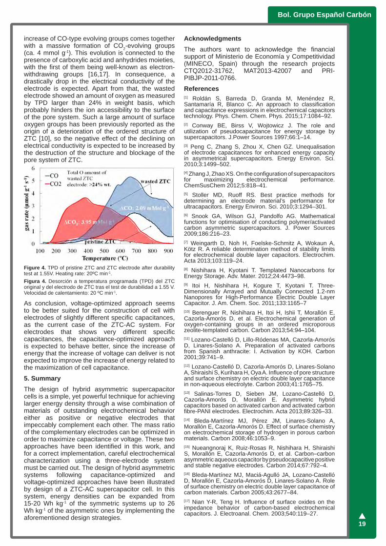
Nevertheless, when the operating voltage was further increased to 1.55V, the cell showed a constant decline on the positive electrode over the first 500 cycles, ending with a sudden malfunction of the cell. Interestingly, the electrode that could not stand to operate to such high voltage was the positive one, ZTC (reaching values of 1.01V), and not the negative one, which was working very close the potential limit, -0.54V. Thanks to the separate potential tracking, it could be possible to detect that ZTC capacitance started to decline after the first 80 cycles. As a consequence of the loss of capacitance in the positive electrode, the balance of window potential for each electrode was shifted towards a larger window for the positive electrode and a shorter window for the negative one. Since a larger positive potential window means that ZTC reached more positive potentials in each cycle, the rate of the electrode degradation increased after every cycle, until the ZTC electrode lost most of its capacitance and massive electrolyte degradation damaged the integrity of the separator, causing a short-circuit of the cell. Post-morten analyses of the electrodes confirmed this degradation mechanism (Fig. 4). Temperature-programmed desorption (TPD) showed that wasted ZTC electrode was overoxidized. The increase of desorbed CO, which is related to neutral and basic surface groups, like phenols, quinones and carbonyls, was higher than 2 mmol g-1. These groups were long time ago identified as net contributors to the pseudocapacitance [16]. Unfortunately, this
Bol. Grupo Español Carbón
19
increase of CO-type evolving groups comes together with a massive formation of CO2-evolving groups (ca. 4 mmol g-1). This evolution is connected to the presence of carboxylic acid and anhydrides moieties, with the first of them being well-known as electron-withdrawing groups [16,17]. In consequence, a drastically drop in the electrical conductivity of the electrode is expected. Apart from that, the wasted electrode showed an amount of oxygen as measured by TPD larger than 24% in weight basis, which probably hinders the ion accessibility to the surface of the pore system. Such a large amount of surface oxygen groups has been previously reported as the origin of a deterioration of the ordered structure of ZTC [10], so the negative effect of the declining on electrical conductivity is expected to be increased by the destruction of the structure and blockage of the pore system of ZTC.
Figure 4. TPD of pristine ZTC and ZTC electrode after durability test at 1.55V. Heating rate: 20ºC min-1.Figura 4. Desorción a temperatura programada (TPD) del ZTC original y del electrodo de ZTC tras el test de durabilidad a 1.55 V. Velocidad de calentamiento: 20 ºC min-1.
As conclusion, voltage-optimized approach seems to be better suited for the construction of cell with electrodes of slightly different specific capacitances, as the current case of the ZTC-AC system. For electrodes that shows very different specific capacitances, the capacitance-optimized approach is expected to behave better, since the increase of energy that the increase of voltage can deliver is not expected to improve the increase of energy related to the maximization of cell capacitance.
5. SummaryThe design of hybrid asymmetric supercapacitor cells is a simple, yet powerful technique for achieving larger energy density through a wise combination of materials of outstanding electrochemical behavior either as positive or negative electrodes that impeccably complement each other. The mass ratio of the complementary electrodes can be optimized in order to maximize capacitance or voltage. These two approaches have been identified in this work, and for a correct implementation, careful electrochemical characterization using a three-electrode system must be carried out. The design of hybrid asymmetric systems following capacitance-optimized and voltage-optimized approaches have been illustrated by design of a ZTC-AC supercapacitor cell. In this system, energy densities can be expanded from 15-20 Wh kg-1 of the symmetric systems up to 26 Wh kg-1 of the asymmetric ones by implementing the aforementioned design strategies.
AcknowledgmentsThe authors want to acknowledge the financial support of Ministerio de Economía y Competitividad (MINECO, Spain) through the research projects CTQ2012-31762, MAT2013-42007 and PRI-PIBJP-2011-0766.
References[1] Roldán S, Barreda D, Granda M, Menéndez R, Santamaría R, Blanco C. An approach to classification and capacitance expressions in electrochemical capacitors technology. Phys. Chem. Chem. Phys. 2015;17:1084–92. [2] Conway BE, Birss V, Wojtowicz J. The role and utilization of pseudocapacitance for energy storage by supercapacitors. J.Power Sources 1997;66:1–14. [3] Peng C, Zhang S, Zhou X, Chen GZ. Unequalisation of electrode capacitances for enhanced energy capacity in asymmetrical supercapacitors. Energy Environ. Sci. 2010;3:1499–502. [4] Zhang J, Zhao XS. On the configuration of supercapacitors for maximizing electrochemical performance. ChemSusChem 2012;5:818–41.[5] Stoller MD, Ruoff RS. Best practice methods for determining an electrode material’s performance for ultracapacitors. Energy Environ. Sci. 2010;3:1294–301. [6] Snook GA, Wilson GJ, Pandolfo AG. Mathematical functions for optimisation of conducting polymer/activated carbon asymmetric supercapacitors. J. Power Sources 2009;186:216–23.[7] Weingarth D, Noh H, Foelske-Schmitz A, Wokaun A, Kötz R. A reliable determination method of stability limits for electrochemical double layer capacitors. Electrochim. Acta 2013;103:119–24. [8] Nishihara H, Kyotani T. Templated Nanocarbons for Energy Storage. Adv. Mater. 2012;24:4473–98. [9] Itoi H, Nishihara H, Kogure T, Kyotani T. Three-Dimensionally Arrayed and Mutually Connected 1.2-nm Nanopores for High-Performance Electric Double Layer Capacitor. J. Am. Chem. Soc. 2011;133:1165–7[10] Berenguer R, Nishihara H, Itoi H, Ishii T, Morallón E, Cazorla-Amorós D, et al. Electrochemical generation of oxygen-containing groups in an ordered microporous zeolite-templated carbon. Carbon 2013;54:94–104. [11] Lozano-Castelló D, Lillo-Ródenas MA, Cazorla-Amorós D, Linares-Solano A. Preparation of activated carbons from Spanish anthracite: I. Activation by KOH. Carbon 2001;39:741–9. [12] Lozano-Castelló D, Cazorla-Amorós D, Linares-Solano A, Shiraishi S, Kurihara H, Oya A. Influence of pore structure and surface chemistry on electric double layer capacitance in non-aqueous electrolyte. Carbon 2003;41:1765–75.[13] Salinas-Torres D, Sieben JM, Lozano-Castelló D, Cazorla-Amorós D, Morallón E. Asymmetric hybrid capacitors based on activated carbon and activated carbon fibre-PANI electrodes. Electrochim. Acta 2013;89:326–33. [14] Bleda-Martínez MJ, Pérez JM, Linares-Solano A, Morallón E, Cazorla-Amorós D. Effect of surface chemistry on electrochemical storage of hydrogen in porous carbon materials. Carbon 2008;46:1053–9. [15] Nueangnoraj K, Ruiz-Rosas R, Nishihara H, Shiraishi S, Morallón E, Cazorla-Amorós D, et al. Carbon–carbon asymmetric aqueous capacitor by pseudocapacitive positive and stable negative electrodes. Carbon 2014;67:792–4. [16] Bleda-Martínez MJ, Maciá-Agulló JA, Lozano-Castelló D, Morallón E, Cazorla-Amorós D, Linares-Solano A. Role of surface chemistry on electric double layer capacitance of carbon materials. Carbon 2005;43:2677–84. [17] Nian Y-R, Teng H. Influence of surface oxides on the impedance behavior of carbon-based electrochemical capacitors. J. Electroanal. Chem. 2003;540:119–27.