design of embedded systems advanced course...
TRANSCRIPT

Design of Embedded Systems Advanced Course
Mario Breakout
Adam Dalentoft, [email protected] Wallstrom, [email protected] Sannum, [email protected]
November 4, 2015

Contents
1 Introduction 2
2 Hardware 32.1 Graphics . . . . . . . . . . . . . . . . . . . . . . . . . . . . . . . . . . . . . 32.2 Controller . . . . . . . . . . . . . . . . . . . . . . . . . . . . . . . . . . . . 5
3 Software 7
4 User Manual 84.1 Installation . . . . . . . . . . . . . . . . . . . . . . . . . . . . . . . . . . . 84.2 Playing the game . . . . . . . . . . . . . . . . . . . . . . . . . . . . . . . . 8
5 Conclusion 95.1 Problems and possible solutions . . . . . . . . . . . . . . . . . . . . . . . . 95.2 Lessons Learned . . . . . . . . . . . . . . . . . . . . . . . . . . . . . . . . 105.3 Contribution Statement . . . . . . . . . . . . . . . . . . . . . . . . . . . . 10
A Eye Candy 11

Abstract
When developing an embedded system there are a lot of important aspects toconsider. Not only are there numerous technical details which have to be consideredin order to end up with an as efficient and cost effective system as possible. Knowl-edge in many sub fields in system development is required as well as a well workingdevelopment process. In our project we encountered numerous obstacles related tomany of these areas, from having to learn a new programming language and style(VHDL) in a fluent fashion, to gain understanding of how many components haveto interact over a system bus and implementation specifics in the VGA standard.
However, in the end, the biggest issues were not technical but rather methodical,we switched from a static waterfall-like method to a more dynamic one. For futureproject more focus should be on how to divide work between developers more effec-tively as well as what should be done when road block issues are encountered.
In the project, we chose to develop a classic arcade game and while the finalproduct was kind of what was described in the initial proposal, a lot of the otherimplementation specific details have been changed in the end.
1

1 Introduction
This is the final report for the project in the Design of Embedded Systems AdvancedCourse (EDA385). The goals of this report is to discuss and conclude the work done dur-ing the project. This includes different hardware and software solutions and the interfacebetween them when implementing a Breakout style game. The project, as mentioned,is a Breakout style video game where the player controls a paddle along the bottom ofthe screen. The paddle is used to bounce a ball against a wall of bricks, with the goalto clear the play field from bricks.
The sections Hardware and Software describe the implementations and design deci-sions made in the project. Following, is a brief user manual that covers installation ofthe software and controlling the game. Finally, the section Conclusions will concludethe report, cover problems encountered and lessons learned.
Figure 1: Architecture overview; blue components represents custom IPs, purple alreadyexisting and yellow is custom software.
As can be seen in Figure 1, the architecture consists of two custom made VHDL
2

modules: one for the input controller and one for the VGA graphics output controller.The hardware modules are communicating with a Microblaze processor, and is thusaccessible by the game logic, via an Axi4Lite bus. Which is one of the major deviationsin the final project from the project proposal. In the proposal FSL buses where used.Another difference is that the controller is based on a rotary encoder instead of the onboard buttons, as mentioned as a possible improvement.
2 Hardware
The physical hardware base is a Nexys 3 Spartan 6 FPGA board[1]. This is configuredwith a MicroBlaze processor[3]. The processor has access to 32kB of BRAM memoryand runs at a clock speed of 100MHz. The FPGA is also configured with a custom madegraphics controller and an user input controller. The custom controllers are communi-cating with the software on the Microblaze over an Axi4Lite bus as well as interrupts.The final system is estimated to use 0.173W which is almost the same as the dual coresetup used during the labs of the introduction course. The comparison with a dualcore setup continues to hold when looking at the utilization of the board with 15% ofSlice Registers used, 40% Slice LUTs and 66% Occupied Slices. It is interesting thatthe custom made graphics core uses almost the same amount of hardware as an extraMicroblaze core would take.
The hardware architecture is created using Xilinx Platform Studio (XPS)[2]. Withthis tool different hardware parts are connected to a MicroBlaze processor and synthe-sized. XPS was also used to get information about the hardware utilization. To build,simulate and test the VHDL code for custom made hardware, ISE Project Navigatorwas used[6].
2.1 Graphics
The graphics controller is responsible for generating the VGA signal which is displayedon the screen. It consists of several separate VHDL components, as follows:
The generated VGA signal is a standard 640x480 pixels 60 Hz signal which requiresa pixel clock at 25MHz. The component vga clk 25 is responsible for taking a 100MHzclock signal and generate a 25MHz signal out of that.
vga controller grabs the 25MHz signal and generates the correct timings, synchro-nization signals and blanking signals which are required for VGA output.
vga src receives the two signals vCount and hCount from vga controller which in-dicates which pixel currently is to be rendered. vga src.vhd contains a number of hardcoded sprites and uses 32 memory mapped registers (currently only 23 are actually used)to determine the color output for a given pixel. All graphics are logically draw in layers,
3
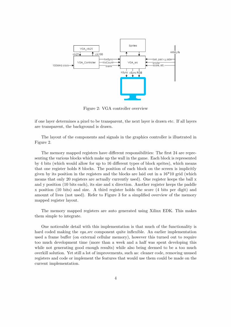
Figure 2: VGA controller overview
if one layer determines a pixel to be transparent, the next layer is drawn etc. If all layersare transparent, the background is drawn.
The layout of the components and signals in the graphics controller is illustrated inFigure 2.
The memory mapped registers have different responsibilities: The first 24 are repre-senting the various blocks which make up the wall in the game. Each block is representedby 4 bits (which would allow for up to 16 different types of block sprites), which meansthat one register holds 8 blocks. The position of each block on the screen is implicitlygiven by its position in the registers and the blocks are laid out in a 16*10 grid (whichmeans that only 20 registers are actually currently used). One register keeps the ball xand y position (10 bits each), its size and x direction. Another register keeps the paddlex position (10 bits) and size. A third register holds the score (4 bits per digit) andamount of lives (not used). Refer to Figure 3 for a simplified overview of the memorymapped register layout.
The memory mapped registers are auto generated using Xilinx EDK. This makesthem simple to integrate.
One noticeable detail with this implementation is that much of the functionality ishard coded making the vga src component quite inflexible. An earlier implementationused a frame buffer (on external cellular memory), however this turned out to requiretoo much development time (more than a week and a half was spent developing thiswhile not generating good enough results) while also being deemed to be a too muchoverkill solution. Yet still a lot of improvements, such as: cleaner code, removing unusedregisters and code or implement the features that would use them could be made on thecurrent implementation.
4

Figure 3: Memory mapped registers overview
2.2 Controller
In the beginning of the project the controller was implemented with the push buttons onthe Nexys 3 board. This implementation was very simple and and built on the xgpio apiavailable with the Microblaze core. The controller worked but the time plan allowed acustom made one instead. In the ’possible improvements’ section in the project proposalboth PS2 controller and analog steering wheel was mentioned. The analog steering wheelwas chosen for the retro feeling.
The final controller is based on a Pmod Rotary Encoder from Diligent [7], describedin Figure 4. The encoder is connected to the first row (6 pins) of the first Pmod connec-tion on the Nexys board. Four of these pins are used in the WHDL module that handlesthe controller and the other two are for power. Two of the four outputs, A and B, areused to decode if the rotary shaft is rotated to the left or to the right. The other twoare BTN, a push button, and SWT, a switch. In Figure 5 a timing diagram of a rightrotation of the shaft is shown.
5

Figure 4: Diligent Pmod Rotary Encoder, used as controller for the paddle [7].
Figure 5: Timing diagram for the Rotary Encoder, this diagram shows the output to Aand B when the rotary shaft is rotated to the right [8].
The VHDL module that handles the input from the rotary encoder is based on anexample implementation provided by Diligent [7]. The provided Debouncer module isused to get rid of noise on the output ports. The module writes a position variable be-tween 0 and 31 to a memory mapped Axi4Lite register as well as the button and switchvalues.
This pcore was integrated in the XPS project and connected to the Axi bus and theexternal ports previously mentioned. The auto-generated .h-file for Axi communicationis slightly modified to provide a get position() function. This is the way the rotaryencoder is integrated in the software.
6

3 Software
The Eclipse based Xilinx Software Development Kit 14.2 (XSDK) is used for for soft-ware development and compilation[4]. Adept 2.4 by Digilent is used to load the compiledsoftware to the Nexys 3 board[5].
The software used in the project are mainly game logic and communication with thehardware. All the software is written in C, both the finished version and the simulationsand tests. To avoid problem with memory allocation and memory leakage, dynamicmemory allocation is completely avoided. Hence no libraries are needed to be includedwhich is relevant as the system got limited memory. Dynamic memory is also a problemin an embedded system, especially this one, as it got no operating system or garbagecollection to control the memory.
The code was developed in several iterations and got simulations to check func-tionality before the final hardware is done. To do these simulations, the C and C++compatible graphics library SDL 2.0 is used [9]. This library is rather advanced in thesense that whole games can be made by it. However, it also got the functions to makerectangles and basic keyboard recognition. Thereby the simulation is just the most basicversion of the program, just to see that the functionality of the game logic is correct.
The complete code which runs on the board is separated in several files in order toachieve some sort of structure. The main game logic is located in the file breakout.c.This file contains initiation of variables, render function, update game and collision de-tection. The collision detection works from a ball point of view. That is, the ball isconstantly checked if it is about to hit another object (brick, wall or paddle). This so-lution deals with the problem of the ball going through the bricks and thereby makingstrange bounces of the brick. Each time the display is updated the collision detection iscalled to determine the preferable action for the ball.
The file vga renderer.c contains all the communication with the vga-controller. Thatis, draw ball, bricks, pad and score board to the screen. This is done by directly settingcoordinates from the software to the registers in the hardware. However, the softwarevalues do not correspond directly to the register value describing the correct position onthe screen. Therefore the values need to be shifted to fit the register vectors. There issupport for several sprites both in software and in hardware. From the write functionsit is possible to specify which sprite is to be written to a specific position on the screen.Each sprite got a corresponding value in hardware which make the sprite handling al-most entirely hardware based.
The file main.c deals with the main loop and the interrupt handling of the program.The main function register an interrupt handler to react on signals from the hardware.When the processor receive an interrupt on the ( vSync) signal this handler is triggered.
7
This in turn calls the game update function which updates the internal state model andrenders any changes on screen. Any calls to hardware is contained in the driver filevga renderer.c.
The memory requirement for the software is low, at around 6 kB. The system has32 kB of memory at its disposal and there is plenty of memory left for variables whichare not allocated until runtime. All graphics are drawn directly by the custom madevga-controller, which makes the memory clear of large sized graphics.
To make the mapping between software and hardware possible several auto generatedfiles are used. These files mainly contain constants that map to registers in hardwareto make it easier to communicate. There are also files with initiation functions for theplatform, namely knob.h and platform.h.
4 User Manual
This section cover the installation and instructions on playing the game.
4.1 Installation
Shipped with this report is both a .bit file ready to be loaded on an Nexys 3 board anda package with XPS and XSDK projects with the implementation of the hard- and soft-ware. The XPS project holds a folder named pcores, where the VHDL implementationof the GPU and controller is saved. The XSDK workspace is named ws and holds the Ccode for the game and interfaces. To prepare the board for the game, a Pmod RotaryEncoder needs to be connected to the top row of the first Pmod connection (JA1) andthe VGA port needs to be connected to a compatible monitor.
4.2 Playing the game
The controls are simple, to steer the paddle left and right rotate the rotary encoder.Push down the rotary encoder to release the ball and start the game. The player can atany time pause the game with the switch on the rotary encoder.
The game starts with a demo level. The first game level loads when the rotary en-coder is pushed down. On each level the player is able to place the paddle anywhereon the screen before starting. When all bricks on the screen are gone, the next level isloaded. The coins only give extra points and do not need to be cleared.
The player has five lives, thus the game ends and restarts when all lives are lost.There are four levels that are looped until the player dies. As a special feature, theplayer can activate a bot that plays automatically on switch eight on the board.
8
5 Conclusion
This section contains problems encountered and lessons learned working on the project.This also include solutions and other thoughts about the work during the process.
5.1 Problems and possible solutions
As the project is rather free in terms of design choices and ways to do things, the onlylimit is the hardware. It is easy to get stuck on a path if it seems to be the right one.In this case, the software was built differently from the beginning. It had a collisiondetection build on comparing the balls coordinates with the coordinates of all the blocksevery rendering cycle. This solution was not only computation heavy but also had arather difficult bug. When the ball came towards the bricks in a specific angle it some-times went straight through the brick instead of bouncing off it. Many hours were putto just try to solve this problems as the rest of the collision detection was working fine.However, this bug was never solved and the collision detection was instead changed tothe one described in the software section. Thereby the bug was avoided and the collisiondetection also got better in terms of computation heaviness. In this case much time wasput on trying to solve the first bug and it was not solved until another member of thegroup (Viktor) read through the code and came up with the new idea. Therefore it isimportant to not get too stuck on one track but try to discuss the problem with someoneelse and find a new path to success.
Similarly, a lot of work was put into developing the first iteration of the graphicscontroller and working with the on board memory chip. In the end these ideas werescrapped when it was realized that there was a great risk that it would not be finished intime. Instead a rather ’hacky’ approach was used and a working graphics controller wasbuilt in roughly one or two days, and refined as more time progressed. Not only was a lotof work wasted but it had also limited the work the other team members could do, sincethey were getting more and more dependent on working graphics. The most valuablelesson learned from this is not to have a grand ambitious plan from the start but ratherstart small with something which at least is working and work the way up from there.Ideally the ’hacky’ approach should have been tried first, changing to the cleaner one ifit was seen as a nice or necessary improvement and if time would have allowed for it.One can kind of see a similarity to the Waterfall vs. Agile development techniques in this.
Testing is very important when it comes to system development. In terms of the soft-ware, as previously mentioned, a simulation was made to make sure the software worksbefore it is put together with the rest of the system. This made the development mucheasier, since one could completely exclude software bugs when putting the whole systemtogether. The other parts of the system got their own tests as well. Hardware uses testbenches in VHDL and the controller part uses basic software to check the output.
Because of the well-tested parts of the system, the completion of it and a running
9
version is easy to put together. Therefore more time can be put into fixing and polishingthe product than into finding and fixing bugs that could have been found in a muchearlier stage of the project.
When first testing the rotary encoder as controller for the game, a big problem wasnoise and stability on the input A and B. This was quickly solved by modifying andusing a part of Diligents example code, the Debouncer. This is acting as a low pass filteron the ports from the encoder.
5.2 Lessons Learned
As previously mentioned both the software (collision detection) and the hardware (GPU)changed during the project, but, before the new implementations, both parts were stuckfor a while. The lesson learned from this is to not be afraid to throw away an implemen-tation and start over with more knowledge from the failed attempt. The road to successusually goes through a couple of iterations of non-optimal ideas before the optimal so-lution is found.
Another lesson learned is that it takes time to compile the hardware, which can leadto a lot of wasted time. As the project went on the group members learned to use thistime to do other useful things, such as work on the presentation, report or some otherpart of the system. Coffee breaks ware also scheduled around hardware compilation.The lesson also included planning of the implementation before compiling and not com-pile for a crash-and-burn test, as sometimes done in smaller software systems.
Something that would be done differently if the project started today is the initialplanning and time estimation. As it turned out the GPU took a lot more time thanexpected. It would have been better to let two people work on it to get a working GPUin to the system earlier and then be able to work on improvements if needed.
5.3 Contribution Statement
Contribution by group member:
Simon implemented VHDL module for the controller, interfaced it in the softwareand tested AXI4Lite communication. Wrote the controller section in this report as wellas the intro, the user manual and hopefully something more...!
Adam wrote game logic and simulation in C. Refactored the code and tested the fullsystem together with Viktor. Wrote the sections in the report connected to software,that is the software section and parts of the conclusion.
Viktor was responsible for designing the graphics controller, writing it in VHDL,Simon helped with the integration and AXI parts. He also wrote the section concerning
10

graphics.
References
[1] Diligent store site for ’Nexys 3 Spartan 6’ FPGA board.http://www.digilentinc.com/Products/Detail.cfm?
NavPath=2,400,897&Prod=NEXYS3&CFID=18681702&CFTOKEN=
933d14222352826d-2F6836B0-5056-0201-02E1D9AB2D87993A
(15/10-15)
[2] Xilinx, Xilinx Platform Studiohttp://www.xilinx.com/tools/xps.htm
(19/10-15)
[3] Xilinx support documentation, MicroBlazehttp://www.xilinx.com/support/documentation/sw_manuals/mb_ref_guide.
(19/10-15)
[4] Xilinx, Xilinx Software Development Kithttp://www.xilinx.com/tools/sdk.htm
(24/5-15) Adept by
[5] Digilent inc.http://www.digilentinc.com/Products/Detail.cfm?NavPath=2,66,828&Prod=
ADEPT2
(19/10-15)
[6] Xilinx, ISE Project Navigatorhttp://www.xilinx.com/tools/projnav.htm
(19/10-15)
[7] Diligent store site for ’PmodENC - Rotary encoder’, this page contains schematics,reference manual and examples available for download. http://digilentinc.com/Products/Detail.cfm?NavPath=2,401,479&Prod=PMOD-ENC (28/9-15)
[8] Diligents reference manual for ’PmodENC - Rotary encoder’. http://digilentinc.com/Data/Products/PMOD-ENC/PmodENC_rm.pdf (28/9-15)
[9] Graphics library for the software simulationhttps://www.libsdl.org/
(13/10-15)
A Eye Candy
11

Figure 6: First level.
Figure 7: First level.
12

Figure 8: Board with controller.
13