design of chebyshev-type iir filters with … of chebyshev-type iir filters with approximately...
TRANSCRIPT

Design of Chebyshev-Type IIR Filters with ApproximatelyLinear Phase Characteristics
Ryousuke Takeuchi, Xi Zhang, Toshinori Yoshikawa, and Yoshinori Takei
Department of Electrical Engineering, Nagaoka University of Technology, Nagaoka, 940-2188 Japan
SUMMARY
Digital filters with a linear phase characteristic areneeded in many applications for signal processing. In thispaper, design of a Chebyshev-type IIR filter with approxi-mate linear phase characteristics in the passband is de-scribed. First, it is shown that a flat stopband can easily berealized by placing multiple zeros at the specified frequencypoints in the stopband. Next, the complex Remez exchangealgorithm is applied to the passband so that the filter designproblem is formulated as an eigenvalue problem. Hence, bysolving the eigenvalue problem, the filter coefficients canbe derived easily. Further, by means of iterative calcula-tions, an equiripple characteristic of the error function inthe passband is obtained. Finally, it is shown that a reverseChebyshev-type IIR filter with an approximate linearphase characteristic can also be obtained by parallelconnection of the proposed Chebyshev-type filter and adelay line. © 2003 Wiley Periodicals, Inc. ElectronComm Jpn Pt 3, 87(2): 1–9, 2004; Published online inWiley InterScience (www.interscience.wiley.com). DOI10.1002/ecjc.10133
Key words: IIR digital filter; Chebyshev-type fil-ter; approximate linear phase characteristic; eigenvalueproblem; complex Remez exchange algorithm.
1. Introduction
Like analog filters, digital filters are classified intofour types—maximally flat type, Chebyshev type, reverse
Chebyshev type, and elliptic type—and are widely used inmany applications [1, 2]. The maximally flat filter has flatcharacteristics both in the passband and in the stopbandwhile the elliptic-type filter has equiripple characteristics inboth stop- and passbands. On the other hand, the Cheby-shev-type and reverse Chebyshev-type filters have anequiripple characteristic in either the pass- or stopband buthave a flat characteristic in the other. These filters areneeded in many image processing applications in order tosuppress ringing and chessboard distortion [2, 3]. In thedesign of these digital filters, the most general way is tomake use of conventional analog filters [1, 2]. However, IIRfilters obtained from analog filters by the s–z transformhave the same orders in the numerator and the denominator.In addition, the phase characteristics of the filter cannot bespecified [1, 2]. Hence, it is necessary to design the digitalfilters directly in the z domain. Many design methods havebeen proposed to date [4–14]. Among them, there aredesign methods taking into consideration the phase charac-teristics of the passband at the same time [7, 12, 14]. Thelinear phase characteristic of the filter is needed in manyapplications for digital signal and image processing. As iswell known, a perfect linear phase characteristic can easilybe realized in an FIR filter by imposing a symmetry condi-tion on the filter coefficients [8, 11]. In the case of an IIRfilter, a perfect linear phase characteristic cannot be realizeddue to causality. In addition to the amplitude characteristic,the phase characteristic must be approximated [7, 12, 14].Hence, let us consider the design of Chebyshev-type IIRfilters with an approximately linear phase characteristic inthe passband.
In this paper, a design method is presented for aChebyshev-type IIR linear phase filter with a flat charac-
© 2003 Wiley Periodicals, Inc.
Electronics and Communications in Japan, Part 3, Vol. 87, No. 2, 2004Translated from Denshi Joho Tsushin Gakkai Ronbunshi, Vol. J86-A, No. 4, April 2003, pp. 364–372
1

teristic in the stopband and an equiripple characteristic inthe passband. In the present design method, it is shown thata flat characteristic in the stopband can easily be realizedby placing multiple zeros at specified frequency points inthe stopband. Hence, the filter design problem is reducedto a problem of approximation of the frequency charac-teristic in the passband. Next, the complex Remez exchangealgorithm is applied to the passband, formulating the filterdesign problem in the form of a generalized eigenvalueproblem [14]. The eigenvalue minimizing the maximumamplitude of the error function is derived. Its correspondingeigenvector specifies the filter coefficients. Further, by re-peating the above calculation process, an equiripple char-acteristic of the error function in the passband can beobtained. It is also shown that a reverse Chebyshev-type IIRfilter with an approximately linear phase characteristic inthe passband can be realized at the same time by parallelconnection of the proposed Chebyshev-type filter and adelay section. Finally, design examples of the IIR Cheby-shev-type low-pass filter and stopband filter are presented,clarifying the usefulness of the present design method.
2. The Chebyshev-Type IIR Filter
The transfer function H(z) of the IIR digital filter isdefined as follows:
where N and M are the orders of the numerator and thedenominator. The filter coefficients an and bn are real andb0 = 1.
In the Chebyshev-type filter, the amplitude charac-teristic is required to be flat in the stopband. Hence,
where ωs is the frequency point specified in the stopbandand K is a parameter expressing the flatness. Also, in thepassband, the desired frequency characteristic of the filteris Hd(e
jω), so that
where |Hd(ejω)| is the desired amplitude characteristic in the
passband and θd(ω) is the desired phase characteristic. In
the case of a linear phase filter, θd(ω) has linear phase andthe group delay is constant.
The difference between the frequency characteristicof the filter and the desired frequency characteristic is theerror function E(ω) defined as
where W(ω) is a weighting function. Hence, the designtarget is to minimize the maximum amplitude of the errorfunction E(ω). Therefore,
3. Design of IIR Low-Pass Filter
Let us next describe the design of an IIR low-passfilter. The flatness condition in the stopband is given by Eq.(2). Here, ωs = π in the case of the low-pass filter. To satisfythis flatness condition, it is necessary to place K multiplezeros at ω = π. Hence, the transfer function H(z) is
If transfer function (6) is used, it is found that the flatnesscharacteristic in the stopband can be realized. Therefore,the problem of design of a low-pass filter is reduced to theproblem of approximation of the frequency characteristicin the passband.
3.1. Setting of the initial value
The desired frequency characteristic of a linear phasefilter in the passband is
where τ is the desired group delay and ωp is the passbandedge frequency. In transfer function (6), the number ofunknown filter coefficients is J = M + N – K + 1. First, L =JJ / 2j initial frequency points ωi (ωp > ω1 > ω2 > . . . >ωL ≥ 0) are selected in the passband [0, ωp]. Here, ∗jdenotes the minimum integer larger than *. If J is even, ωi(ωL ≠ 0) is selected at equal intervals as shown in Fig. 1(a).If J is odd, ωi is selected from ωL = 0 as shown in Fig. 1(b).Next, since the design target is minimization of the maxi-mum amplitude of the error function, the amplitude of theerror function at these frequency points ωi is zero:
(1)
(2)
(3)
(4)
(5)
(6)
(7)
2

When Eq. (8) is substituted into Eq. (7), we have
Here, D(ω) = (2cos ω2)K. Since b0 = 1, Eq. (9) is separated
into the real part and the imaginary part:
If J is even, the numbers of Eqs. (10) and (11) are L in bothcases so that the total is 2L = J. If J is odd, ωL = 0, the numberof Eqs. (11) is one fewer than the number of Eqs. (10) andis L – 1. Therefore, the total is 2L – 1 = J. Hence, by solvingEqs. (10) and (11), the filter coefficients cn and bm areuniquely determined.
3.2. Formulation by complex Remez exchangealgorithm
From the filter coefficients obtained in Section 3.1,the error function E(ω) is derived and its extremum fre-quency points ωi (ωp = ω1 > ω2 > . . . ≥ 0) are sought. As aresult, the obtained error function is not necessarily anequiripple characteristic. Hence, by using the complex Re-mez exchange algorithm, a formulation is carried out tomake the function an equiripple characteristic. As shown inFig. 1, the number of extremum frequency points ωi is L +1 if J is even and L if J is odd (including the passband edgefrequency ωp). Let θe(ωi) be the phase of the error functionat the extremum frequency points ωi. At these extremumfrequency points ωi, the amplitudes of the error function aremade equal in the formulation:
where δ is the amplitude of the error function. Hence, if Eq.(12) is separated into the real part and the imaginary part,the following are obtained:
It is found from Fig. 1 that the number of Eqs. (14) is fewerby one than the number of Eqs. (13) because ωL+1 = 0 if Jis even. Hence, when Eqs. (13) and (14) are combined, thereare 2L + 1 = J + 1 equations. When J is odd, the total is 2L= J + 1, because ωL > 0. Hence, the number of Eqs. (13) and(14) is J + 1 in each case regardless of whether J is even orodd. If Eqs. (13) and (14) are expressed in matrix form, theyare reduced to the following generalized eigenvalue prob-lem [14]:
(8)
(9)
(10)
(11)
(12)
(13)
(14)
Fig. 1. Selection of initial frequency points for low-passfilters. (a) Even J; (b) odd J.
3
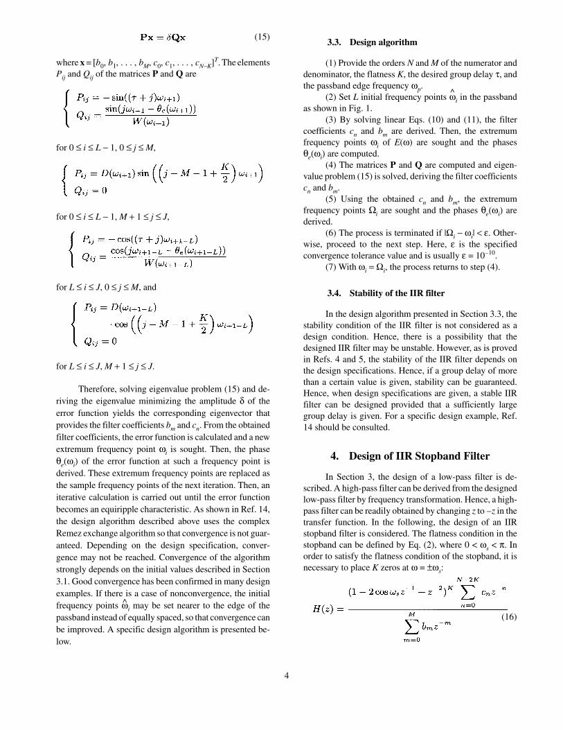
where x = [b0, b1, . . . , bM, c0, c1, . . . , cN−K]T. The elementsPij and Qij of the matrices P and Q are
for 0 ≤ i ≤ L − 1, 0 ≤ j ≤ M,
for 0 ≤ i ≤ L − 1, M + 1 ≤ j ≤ J,
for L ≤ i ≤ J, 0 ≤ j ≤ M, and
for L ≤ i ≤ J, M + 1 ≤ j ≤ J.
Therefore, solving eigenvalue problem (15) and de-riving the eigenvalue minimizing the amplitude δ of theerror function yields the corresponding eigenvector thatprovides the filter coefficients bm and cn. From the obtainedfilter coefficients, the error function is calculated and a newextremum frequency point ωi is sought. Then, the phaseθe(ωi) of the error function at such a frequency point isderived. These extremum frequency points are replaced asthe sample frequency points of the next iteration. Then, aniterative calculation is carried out until the error functionbecomes an equiripple characteristic. As shown in Ref. 14,the design algorithm described above uses the complexRemez exchange algorithm so that convergence is not guar-anteed. Depending on the design specification, conver-gence may not be reached. Convergence of the algorithmstrongly depends on the initial values described in Section3.1. Good convergence has been confirmed in many designexamples. If there is a case of nonconvergence, the initialfrequency points ωi may be set nearer to the edge of thepassband instead of equally spaced, so that convergence canbe improved. A specific design algorithm is presented be-low.
3.3. Design algorithm
(1) Provide the orders N and M of the numerator anddenominator, the flatness K, the desired group delay τ, andthe passband edge frequency ωp.
(2) Set L initial frequency points ωi in the passbandas shown in Fig. 1.
(3) By solving linear Eqs. (10) and (11), the filtercoefficients cn and bm are derived. Then, the extremumfrequency points ωi of E(ω) are sought and the phasesθe(ωi) are computed.
(4) The matrices P and Q are computed and eigen-value problem (15) is solved, deriving the filter coefficientscn and bm.
(5) Using the obtained cn and bm, the extremumfrequency points Ωi are sought and the phases θe(ωi) arederived.
(6) The process is terminated if |Ωi − ωi| < ε. Other-wise, proceed to the next step. Here, ε is the specifiedconvergence tolerance value and is usually ε = 10–10.
(7) With ωi = Ωi, the process returns to step (4).
3.4. Stability of the IIR filter
In the design algorithm presented in Section 3.3, thestability condition of the IIR filter is not considered as adesign condition. Hence, there is a possibility that thedesigned IIR filter may be unstable. However, as is provedin Refs. 4 and 5, the stability of the IIR filter depends onthe design specifications. Hence, if a group delay of morethan a certain value is given, stability can be guaranteed.Hence, when design specifications are given, a stable IIRfilter can be designed provided that a sufficiently largegroup delay is given. For a specific design example, Ref.14 should be consulted.
4. Design of IIR Stopband Filter
In Section 3, the design of a low-pass filter is de-scribed. A high-pass filter can be derived from the designedlow-pass filter by frequency transformation. Hence, a high-pass filter can be readily obtained by changing z to –z in thetransfer function. In the following, the design of an IIRstopband filter is considered. The flatness condition in thestopband can be defined by Eq. (2), where 0 < ωs < π. Inorder to satisfy the flatness condition of the stopband, it isnecessary to place K zeros at ω = ±ωs:
(15)
(16)
4

By using transfer function (16), a flat stopband can berealized. The desired frequency characteristic Hd(e
jω) in thepassband is
In the case of a real coefficient filter, the phase of the filterat ω = π is θ(π) = nπ (n is an integer). Therefore, it isnecessary that θ0 = (n + τ)π. Therefore, the complex Remezexchange algorithm can be applied to the passband fordesign as in the case of the low-pass filter. Here, in the caseof the stopband filter, there are two passbands. The settingof the initial frequency points is shown in Fig. 2. Thenumber of unknown filter coefficients in Eq. (16) is J = M+ N – 2K + 1. If J is even, then L of ωi are selected such that0 < ωi < π. The number of generated extremum frequencypoints ωi is L + 2 (including ωi = 0 and π). Since the numberneeded for the formulation by the complex Remez ex-change algorithm is L + 1, either ωi = 0 or ωi = π with asmaller amplitude of the error function is eliminated. Theremaining L + 1 extremum frequency points are used as thesample frequency points. When J is odd, either ωi = 0 orωi = π is selected and then L sample frequency points areselected such that ωi ≠ 0, π from the generated extremumfrequency points. Also, with regard to the bandpass filter,the design method described above cannot be applied di-rectly; this situation will be studied in the future.
5. The IIR Reverse Chebyshev-Type Filter
A Chebyshev-type filter H(z) designed by the abovedesign method and a delay line z–1 are connected in parallelas shown in Fig. 3 to construct a new filter G(z). The transferfunction of G(z) is
where I is an integer. Now H(z) is designed by letting thedesired group delay be τ = I. In the case of the stopbandfilter, let θ0 = 0. Hence, it is found from Eq. (18) that thepassband of H(z) becomes the stopband of G(z) with anequiripple characteristic. Also, the amplitude of H(z) is 0 inthe stopband. Therefore, this band becomes the passbandof G(z). Since H(z) has a flat characteristic in the stopband,the amplitude characteristic |G(ejω)| and the group delayτ(ω) of G(z) satisfy
and are flat. Hence, an IIR reverse Chebyshev-type filterwith a flat group delay can be realized at the same time.However, since the desired group delay τ is limited by theinteger I, a reverse Chebyshev-type filter with a nonintegerdelay cannot be designed with this configuration.
6. Design Examples
[Design Example 1] As the design specifications, letN = 15, M = 6, K = 10, and ωp = 0.3π. Then, a Chebyshev-type low-pass filter with τ = 12 is designed. The amplitudecharacteristic of the error function of the obtained filter isplotted in Fig. 4 as the solid line. It is found that an
(17)
Fig. 2. Selection of initial frequency points forbandstop filters. (a) Even J; (b) odd J.
(18)
Fig. 3. Parallel connection of H(z) and a delay section.
(19)
(20)
5

equiripple characteristic is realized. The amplitude charac-teristics of the error functions of the filters designed with τ= 10.5 and τ = 13.5 are also presented. The amplitude andgroup delay characteristics of these filters are shown inFigs. 5 and 6. All of the obtained filters are stable. Thepole-zero locations of the filter with τ = 12 are shown inFig. 7. Also, from the Chebyshev-type low-pass filter H(z)with τ = 12, a reverse Chebyshev-type high-pass filter G(z)is derived. The amplitude and group delay characteristicsof G(z) are shown in Figs. 8 and 9.
[Design Example 2] As the design specifications, letN + M = 19, K = 10, τ = 11, and ωp = 0.48π. Design examplesof Chebyshev-type low-pass filters with N and M varied areshown. In the case of M = 0, this yields an FIR filter. Sincethe group delay is not half the order, the filter is not a
Fig. 5. Magnitude responses of low-pass filters inExample 1.
Fig. 6. Group delays of low-pass filters in Example 1.
Fig. 7. Pole-zero location of low-pass filter in Example 1.
Fig. 8. Magnitude response of high-pass filter inExample 1.
Fig. 4. Magnitude responses of error functions inExample 1.
6

Fig. 9. Group delay of high-pass filter in Example 1.
Fig. 10. Magnitude responses of error functions inExample 2.
Fig. 11. Magnitude responses of low-pass filters inExample 2.
Fig. 12. Group delays of low-pass filters in Example 2.
Fig. 13. Magnitude response of error function inExample 3.
Fig. 14. Magnitude responses of bandstop and bandpassfilters in Example 3.
7

perfectly linear phase FIR filter. The amplitude charac-teristic of the error function of the designed filter is shownin Fig. 10, where it is seen that an equiripple characteristiccan be obtained. In comparison with the FIR filter with M= 0, the filter with M = 4 has the smallest error. Theamplitude and group delay characteristics of the obtainedlow-pass filter are shown in Figs. 11 and 12. The IIR filterswith M = 2 and M = 4 are found to have smaller amplitudeand group delay errors than the FIR filter with M = 0.
[Design Example 3] As the design specifications, letN = M = 10, K = 3, τ = 8, θ0 = 0, ωp1 = 0.2π, ωp2 = 0.8π,and ωs = 0.48π. Then, a Chebyshev-type stopband filter isdesigned. In this design example, four initial frequencypoints ωi are placed in the passband [0, ωp1] and anotherfour in the passband [ωp2, π]. The amplitude characteristicof the error function of the designed filter is shown in Fig.13 and is found to be of equiripple type. The amplitude andgroup delay characteristics of the filter are plotted in Figs.14 and 15 as solid lines. The amplitude and group delaycharacteristics of the reverse Chebyshev-type bandpass fil-ter G(z) obtained from Eq. (18) are plotted in Figs. 14 and15 as dotted lines.
7. Conclusions
In this paper, a design method has been proposed fora Chebyshev-type IIR filter with an approximately linearphase characteristic in the passband. In this design method,it is first shown that a flat characteristic in the stopband canbe easily realized by placing multiple zeros at the specifiedfrequency points in the stopband. Next, the complex Remezexchange algorithm is applied to the passband and the filterdesign problem is formulated in the form of a generalizedeigenvalue problem. Hence, by solving the eigenvalueproblem, the filter coefficients can be readily obtained.
Further, by iterative calculations, an equiripple charac-teristic of the error function in the passband can be obtained.In addition, by parallel connection of the proposed Cheby-shev-type filter and a delay section, a reverse Chebyshev-type IIR filter with an approximately linear phasecharacteristic in the passband can be realized at the sametime. Finally, design examples are presented for IIR Che-byshev-type low-pass filters and a stopband filter, demon-strating the usefulness of the present design method. Futuretopics of study include the design of a reverse Chebyshev-type linear phase filter with noninteger delay.
REFERENCES
1. Mitra SK, Kaiser JF. Handbook for digital signalprocessing. John Wiley & Sons; 1993.
2. Strang G, Nguyen T. Wavelets and filter banks.Wellesley-Cambridge Press; 1996.
3. Kiya H. Understandable digital image processing.CQ Publications; 1996.
4. Thiran JP. Recursive digital filters with maximallyflat group delay. IEEE Trans Circuit Theory1971;18:659–664.
5. Thiran JP. Equal-ripple delay recursive digital filters.IEEE Trans Circuit Theory 1971;18:664–669.
6. Darlington S. Filters with Chebyshev stopbands, flatpassbands, and impulse responses of finite duration.IEEE Trans Circuits Syst 1978;25:966–975.
7. Nishikawa K, Takeda K. IIR low pass digital filterwith flat amplitude in the pass band with maximallyflat delays and equal ripple attenuations in the stopband. Trans IEICE 1981;J64-A:819–826.
8. Vaidyanathan PP. Optimal design of linear phase FIRdigital filters with very flat passbands and equiripplestopbands. IEEE Trans Circuits Syst 1985;32:904–917.
9. Zhang X, Iwakura H. Design of IIR digital filtersbased on eigenvalue problem. IEEE Trans SignalProcess 1996;44:1325–1333.
10. Selesnick IW, Burrus CS. Generalized digital Butter-worth filter design. IEEE Trans Signal Process1996;46:1688–1694.
11. Selesnick IW, Burrus CS. Exchange algorithms forthe design of linear phase FIR filters and differentia-tors having flat monotonic passbands and equiripplestopbands. IEEE Trans Circuits Syst II: Analog andDigital Signal Processing 1996;43:671–675.
12. Hegde R, Shenoi BA. Magnitude approximation ofdigital filters with specified degrees of flatness andconstant group delay characteristics. IEEE Trans Cir-cuits Syst II: Analog and Digital Signal Processing1998;45:1476–1486.
Fig. 15. Group delays of bandstop and bandpass filtersin Example 3.
8

13. Zhang X, Yoshikawa T. Design of IIR digital filterswith equal ripple characteristics in the pass bandand a flat pass band. Trans IEICE 1999;J82-A:317–324.
14. Zhang X, Suzuki K, Yoshikawa T. Complex Cheby-shev approximation for IIR digital filters based oneigenvalue problem. IEEE Trans Circuits Syst II:Analog and Digital Signal Processing 2000;47:1429–1436.
AUTHORS (from left to right)
Ryousuke Takeuchi (student member) graduated from the Department of Electrical and Electronic Systems at NagaokaUniversity of Technology in 2002 and is now in the M.S. program. He has been engaged in research on digital signal processing.
Xi Zhang (member) graduated from the Department of Electronic Engineering at Nanjing Aerospace and AeronauticalUniversity, China, in 1984 and completed the doctoral program at the University of Electro-Communications in 1993, receivinga D.Eng. degree. In 1984, he became a research associate at Nanjing Aerospace and Aeronautical University. He moved to theUniversity of Electro-Communications in 1993, and is now an associate professor at Nagaoka University of Technology. Hewas a Visiting Scholar supported by the Ministry of Education at Massachusetts Institute of Technology in 2000–2001. Hereceived a third-class award for National Science and Technology Advancement in China in 1987, and an LSI IP DesignChallenge Award in 2002. Since 2002, he has been an associate editor of IEEE Signal Processing Letters. His research interestsare digital signal processing, image processing, filter design theory, approximation theory, and wavelet and image compression.He is a senior member of IEEE.
Toshinori Yoshikawa (member) graduated from the Department of Electronic Engineering at Tokyo Institute ofTechnology in 1971 and completed the doctoral program in 1976, receiving a D.Eng. degree. After serving as a research associateand then lecturer at Saitama University, he became an associate professor at Nagaoka University of Technology, and is now aprofessor. He has been engaged in research on digital signal processing and computer software applications. He is a memberof IEEE.
Yoshinori Takei (member) graduated from the Department of Mathematics at Tokyo Institute of Technology in 1990 andcompleted the M.S. program in 1992. In 2000, he completed the doctoral program in physical information, receiving a D.Eng.degree. From 1992 to 1995, he was affiliated with Kawatetsu Information Systems Co. From 1999 to 2000, he was a researchassociate at Tokyo Institute of Technology. Since 2000, he has been a research associate at Nagaoka University of Technology,and is engaged in research on computational complexity and digital signal processing. He is a member of LA, SIAM, ACM,AMS, and IEEE.
9