design of bop systems for the am600
TRANSCRIPT

Transactions of the Korean Nuclear Society Autumn Meeting
Gyeongju, Korea, October 29-30, 2015
Design of BOP Systems for the AM600
Victor Otieno Ouma, M. Gomaa Abdoelatef, Na Hyungjooh, Robert Field*
KEPCO International Nuclear Graduate School (KINGS), 658-91 Haemaji-ro, Seosaeng-myeon, Ulju-gun, 689-882
Republic of Korea, *Corresponding author: [email protected]
1. Introduction
This paper describes the salient elements of BOP
system design for the Advanced Modern 600 MWe
(AM600) nuclear steam cycle. The AM600 Turbine-
Generator (T/G) which converts thermodynamic energy
to electrical energy is designed with a single-flow High
Pressure Turbine (HPT) section and a single cylinder,
two-flow Low Pressure Turbine (LPT) section (as
described in detail elsewhere). Targeted for emergent
nuclear countries with smaller grid capacity and/or large
seasonal variation in grid frequency, the design is
intended to be appropriate as an initial Nuclear Power
Plant (NPP) installation. The AM600 shaftline is
designed to have low capital and installation cost with
robust resistance to torsional vibration and other
operational insults.
This paper specifically examines the critical features
of the Balance of Plant (BOP) design to support the
AM600 T/G. The principal objectives for this BOP
design are:
i. reduce BOP component count to reduce overall
cost of the design, fabrication, and construction,
and to simplify operation, maintenance, testing,
and inspections,
ii. maximize use of modular fabrication and
construction techniques, and
iii. reduce turbine building volume.
This paper will look at three areas of BOP design for
the AM600 which differ from conventional design and
employ special features or approaches:
i. Power Train Pump (PTP) design,
ii. Feedwater Heater (FWH) design, and
iii. Extraction Steam (ES) piping design.
2. System Description
2.1 Power Train Pumps (PTPs)
A reduction in the component count for power train
pumps results in an associated reduction in supporting
subcomponents such as pump drivers, switchgear, relays,
and instrumentation. On the mechanical side, supporting
component reductions include minimum flow control
valves, isolation/block valves, lubricating oil systems,
and others. Minimizing the number of PTPs also reduces
operational complexity and the station burden of
component maintenance, testing, and inspections. In
addition the design for the AM600 PTP system
eliminates the complex steam turbine drive units for the
Steam Generator Feedwater Pumps (SGFPs). Rather,
two, 100% capacity motor driven SGFPs are driven by
electronic Variable Frequency Drive (VFD) units.
2.1.1 Condensate Pumps (CPs)
Each CP is coupled with a Condensate Booster Pump
(CBP), sharing a common double shafted motor. Speed
reduction for the CP is performed by a gearset. In the
targeted market with a 50Hz grid frequency, the CP is
designed to run at 1200 rpm via the gearset while the
CBP operates at the operating speed of the motor, or
3000 rpm. Fig. 1 illustrates this arrangement.
Fig. 1. Coupled condensate and condensate booster pump
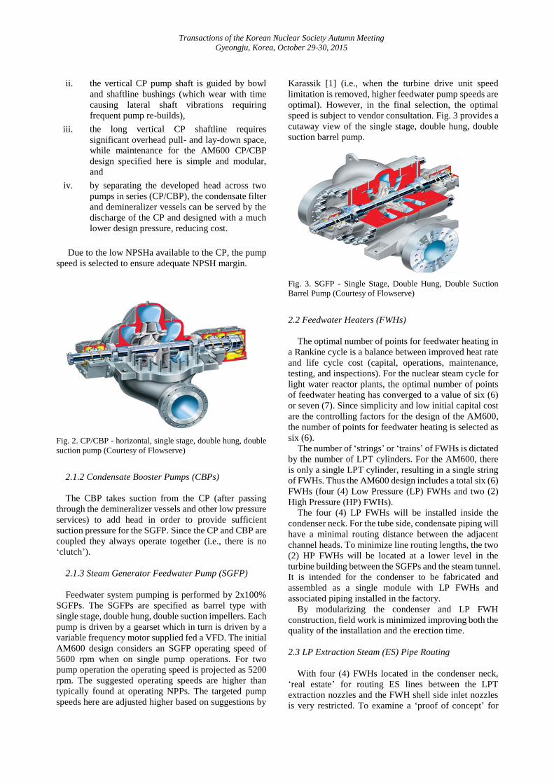
The CPs and the CBPs are specified as standard design,
single stage, double hung, and double suction horizontal
pumps. This style of pump is the workhorse of the
customer specified pump industry and is known for long-
term, reliable performance. Fig. 2 shows a typical design
for the single stage, double hung, double suction
horizontal pump.
This CP/CBP configuration was adopted to address
challenges associated with the vertical, multi-stage, high
head CP pumps which include:
i. seasonal grid frequency drift in many emergent
markets is not compatible with the long
shaftline and associated natural frequencies of
the vertical CP, potentially leading to damaging
modes of resonant vibration,
Transactions of the Korean Nuclear Society Autumn Meeting
Gyeongju, Korea, October 29-30, 2015
ii. the vertical CP pump shaft is guided by bowl
and shaftline bushings (which wear with time
causing lateral shaft vibrations requiring
frequent pump re-builds),
iii. the long vertical CP shaftline requires
significant overhead pull- and lay-down space,
while maintenance for the AM600 CP/CBP
design specified here is simple and modular,
and
iv. by separating the developed head across two
pumps in series (CP/CBP), the condensate filter
and demineralizer vessels can be served by the
discharge of the CP and designed with a much
lower design pressure, reducing cost.
Due to the low NPSHa available to the CP, the pump
speed is selected to ensure adequate NPSH margin.
Fig. 2. CP/CBP - horizontal, single stage, double hung, double
suction pump (Courtesy of Flowserve)
2.1.2 Condensate Booster Pumps (CBPs)
The CBP takes suction from the CP (after passing
through the demineralizer vessels and other low pressure
services) to add head in order to provide sufficient
suction pressure for the SGFP. Since the CP and CBP are
coupled they always operate together (i.e., there is no
‘clutch’).
2.1.3 Steam Generator Feedwater Pump (SGFP)
Feedwater system pumping is performed by 2x100%
SGFPs. The SGFPs are specified as barrel type with
single stage, double hung, double suction impellers. Each
pump is driven by a gearset which in turn is driven by a
variable frequency motor supplied fed a VFD. The initial
AM600 design considers an SGFP operating speed of
5600 rpm when on single pump operations. For two
pump operation the operating speed is projected as 5200
rpm. The suggested operating speeds are higher than
typically found at operating NPPs. The targeted pump
speeds here are adjusted higher based on suggestions by
Karassik [1] (i.e., when the turbine drive unit speed
limitation is removed, higher feedwater pump speeds are
optimal). However, in the final selection, the optimal
speed is subject to vendor consultation. Fig. 3 provides a
cutaway view of the single stage, double hung, double
suction barrel pump.
Fig. 3. SGFP - Single Stage, Double Hung, Double Suction
Barrel Pump (Courtesy of Flowserve)
2.2 Feedwater Heaters (FWHs)
The optimal number of points for feedwater heating in
a Rankine cycle is a balance between improved heat rate
and life cycle cost (capital, operations, maintenance,
testing, and inspections). For the nuclear steam cycle for
light water reactor plants, the optimal number of points
of feedwater heating has converged to a value of six (6)
or seven (7). Since simplicity and low initial capital cost
are the controlling factors for the design of the AM600,
the number of points for feedwater heating is selected as
six (6).
The number of ‘strings’ or ‘trains’ of FWHs is dictated
by the number of LPT cylinders. For the AM600, there
is only a single LPT cylinder, resulting in a single string
of FWHs. Thus the AM600 design includes a total six (6)
FWHs (four (4) Low Pressure (LP) FWHs and two (2)
High Pressure (HP) FWHs).
The four (4) LP FWHs will be installed inside the
condenser neck. For the tube side, condensate piping will
have a minimal routing distance between the adjacent
channel heads. To minimize line routing lengths, the two
(2) HP FWHs will be located at a lower level in the
turbine building between the SGFPs and the steam tunnel.
It is intended for the condenser to be fabricated and
assembled as a single module with LP FWHs and
associated piping installed in the factory.
By modularizing the condenser and LP FWH
construction, field work is minimized improving both the
quality of the installation and the erection time.
2.3 LP Extraction Steam (ES) Pipe Routing
With four (4) FWHs located in the condenser neck,
‘real estate’ for routing ES lines between the LPT
extraction nozzles and the FWH shell side inlet nozzles
is very restricted. To examine a ‘proof of concept’ for
Transactions of the Korean Nuclear Society Autumn Meeting
Gyeongju, Korea, October 29-30, 2015
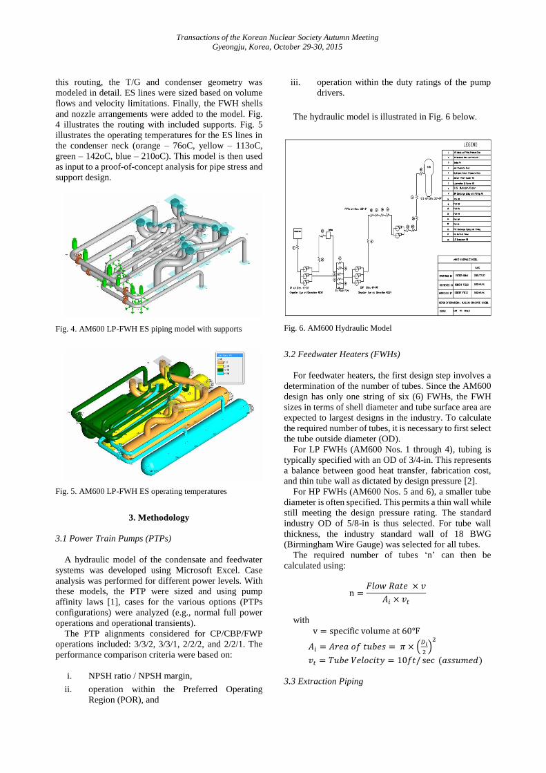
this routing, the T/G and condenser geometry was
modeled in detail. ES lines were sized based on volume
flows and velocity limitations. Finally, the FWH shells
and nozzle arrangements were added to the model. Fig.
4 illustrates the routing with included supports. Fig. 5
illustrates the operating temperatures for the ES lines in
the condenser neck (orange – 76oC, yellow – 113oC,
green – 142oC, blue – 210oC). This model is then used
as input to a proof-of-concept analysis for pipe stress and
support design.
Fig. 4. AM600 LP-FWH ES piping model with supports
Fig. 5. AM600 LP-FWH ES operating temperatures
3. Methodology
3.1 Power Train Pumps (PTPs)
A hydraulic model of the condensate and feedwater
systems was developed using Microsoft Excel. Case
analysis was performed for different power levels. With
these models, the PTP were sized and using pump
affinity laws [1], cases for the various options (PTPs
configurations) were analyzed (e.g., normal full power
operations and operational transients).
The PTP alignments considered for CP/CBP/FWP
operations included: 3/3/2, 3/3/1, 2/2/2, and 2/2/1. The
performance comparison criteria were based on:
i. NPSH ratio / NPSH margin,
ii. operation within the Preferred Operating
Region (POR), and
iii. operation within the duty ratings of the pump
drivers.
The hydraulic model is illustrated in Fig. 6 below.
Fig. 6. AM600 Hydraulic Model
3.2 Feedwater Heaters (FWHs)
For feedwater heaters, the first design step involves a
determination of the number of tubes. Since the AM600
design has only one string of six (6) FWHs, the FWH
sizes in terms of shell diameter and tube surface area are
expected to largest designs in the industry. To calculate
the required number of tubes, it is necessary to first select
the tube outside diameter (OD).
For LP FWHs (AM600 Nos. 1 through 4), tubing is
typically specified with an OD of 3/4-in. This represents
a balance between good heat transfer, fabrication cost,
and thin tube wall as dictated by design pressure [2].
For HP FWHs (AM600 Nos. 5 and 6), a smaller tube
diameter is often specified. This permits a thin wall while
still meeting the design pressure rating. The standard
industry OD of 5/8-in is thus selected. For tube wall
thickness, the industry standard wall of 18 BWG
(Birmingham Wire Gauge) was selected for all tubes.
The required number of tubes ‘n’ can then be
calculated using:
n =𝐹𝑙𝑜𝑤 𝑅𝑎𝑡𝑒 × 𝑣
𝐴𝑖 × 𝑣𝑡
with
v = specific volume at 60℉
𝐴𝑖 = 𝐴𝑟𝑒𝑎 𝑜𝑓 𝑡𝑢𝑏𝑒𝑠 = 𝜋 × (𝐷𝑖
2)
2
𝑣𝑡 = 𝑇𝑢𝑏𝑒 𝑉𝑒𝑙𝑜𝑐𝑖𝑡𝑦 = 10𝑓𝑡/ sec (𝑎𝑠𝑠𝑢𝑚𝑒𝑑)
3.3 Extraction Piping

Transactions of the Korean Nuclear Society Autumn Meeting
Gyeongju, Korea, October 29-30, 2015
AM600 LP-FWH ES layout and analysis were
performed using AutoPIPETM software [3].
4. Results
4.1 Power Train Pumps (PTPs)
Tables I, II and III below provide results for hydraulic
modeling of CPs, CBPs, and SGFPs. Evaluation criteria
include calculations of NPSH ratio, motor power, flow,
and pressure [4]. Since the pumps are designed as 3x50%
(CP, CBP), and 2x100% (SGFP), the best efficiency is
achieved with 2/2/1 operations.
Table I: CP Design Analysis
Parameter Unit 101.5% A.C.1
Pumps in Operation 3 2
Speed rpm 1200 1200
Flow per Pump gpm 5576 8364
Head ft 420 380
NPSHa ft 27.5 27.5 1.2~1.5
NPSH ratio ft 1.45 1.38
Motor Power hp 780 995
Flow vs. BEP % 66 98 70~120
1) A.C. – Acceptance Criterion
Table II: CBP Design Analysis
Power Level Unit 101.50% A.C.
Pumps in Operation 3 2
Speed rpm 3000 3000
Flow per Pump gpm 5579 8368
Head ft 1450 1200
NPSHa ft 253 213
NPSH ratio ft 4.08 2.10 2.0~4.0
Motor Power hp 2660 3144
Total Motor Power hp 3439 4140
Total Power Demand hp 10318 8280
Flow vs. BEP % 66 99 70~120
Table III: Feed Water Pumps Design Result
Power Level Unit 101.50% A.C.
Pumps
Operation 3/3/2 2/2/2 3/3/1 2/2/1
Speed rpm 5200 5200 5600 5600
Flow per
Pump gpm 9098 9078 18156 18156
Head H ft 2800 2800 2650 2650
NPSHm ft 6.6 5.65 6.24 5.37 5.0~7.0
NPSHa ft 1254 1080 1254 1080
Motor Power hp 8103 8103 14044 14044
Total Power
Demand hp 16206 16206 14044 14044
BEP % 73 73 113.50 113.50 80~120
Design Option Selection Criteria
i. NPSH ratio at 101.5% Power level - All the
design options satisfy the NPSH margin
requirement [5]
ii. Design Flow vs. BEP - 2/2/1 option offers
acceptable flow within the POR for all the pump
operation options
iii. Motor Power Consumption - The result from
the graph show that 2/2 CP/CBP and 1 FWP
pump train operation indicates limiting driver
duty, but overall has less total motor power
consumption
4.2 Feedwater Heaters (FWHs)
The calculated minimum number of tubes for the LP
FWHs is 1,610 and for the HP FWHs is 2,464. Industry
standard plugging margins are 10% for these heaters.
However, since the AM600 design only employs a single
string of FWHs, special design considerations for FWH
Out-Of-Service (OOS) operations are required. In the
event of FWH OOS, the typical design isolates the entire
string. The remaining strings plus bypass flow are then
used for continued operations.
For the AM600, string isolation is not an option.
Rather, an individual FWH will be isolated in the event
of tube rupture (or failed drain control valve), and all of
the remaining FWHs will be operated within their
capability (with necessary bypass). Thus to maximize
operating capacity with a FWH OOS, all FWHs were
oversized. In the case of LP FWHs, the shell diameter
was maximized to the available space in the condenser
neck.
Fig. 7. Drilling pattern for FWHs 1 to 4
For the conceptual AM600 tube sheet arrangements,
2,603 tubes are used for LP FWHs and 3,478 tubes for

Transactions of the Korean Nuclear Society Autumn Meeting
Gyeongju, Korea, October 29-30, 2015
HP FWHs. The margin above the minimum number of
tubes is ~60% for LP FWHs and ~70% for HP FWHs
With this design, a very large overload flow for
operations with FWH OOS can be specified. This design
also results in good capacity to handle the very large
drain cooler flows for the fully cascading AM600 design
(i.e., drain flows in the LP FWH No. 1 approach 3,600
m3/hr, or 16,000 gpm). The ‘oversized’ tube bundles will
reduce steam velocities for FWH OOS operations,
reducing the potential for condensing zone vibration
damage. Similarly, the ‘oversized’ bundles will reduce
the limiting velocities in the drain cooler (which occur at
full power) minimizing the potential for damaging drain
cooler vibration. Fig.’s 7 and 8 illustrate the tube sheet
layout for LP FWHs and HP FWHs, respectively.
Fig. 8. Drilling pattern for FWHs 5 and 6
The AM600 FWHs are standard design two-zone
heaters with horizontal U-tube bundles [6]. The current
design assumes all FWHs include an integral drain
cooling zone. This approach requires consultation with
FWH vendors for the lowest pressure heaters to
determine if an external drain cooler is required.
Fig. 9 shows the typical design for the LP FWHs.
FWH No. 1 will be located in condenser neck. The shell
design includes four (4) 30-in ES nozzles, one 30-in
drain inlet nozzle above the flash chamber, and one
bottom mounted 30-in drain outlet nozzle. Channel head
nozzles are each 30-in. The channel heads for the LP
FWHs are designed as full access with an internally
sealed pass partition box.
Fig. 9. Schematic drawing of FWH 1
Table IV outlines the nozzle design for FWH Nos. 1
to 4.
Table IV: FWH nozzles
FWH 1 FWH 2 FWH 3 FWH 4
ES Inlet Diameter 30" 22" 20" 16"
Number 4 4 2 2
Drain
Inlet
Diameter 30" 30" 22" 22"
Number 1 1 1 1
Drain
Outlet
Diameter 30" 22" 22" 22"
Number 1 1 1 1
Channel
Head
Inlet 30" 30" 30" 30"
Outlet 30" 30" 30" 30"
4.3 LP Extraction Piping
Fig.’s 10 and 11 illustrate the design process for
support ES lines in the condenser neck. Fig. 10 indicates
bending stress for unsupported lines (red is high stress,
blue – low). By adding vertical supports and guides and
expansion joints, significant stress reduction is possible.
Fig. 10. The stress distribution for AM600 LP-FWH ES Piping
Model without supports

Transactions of the Korean Nuclear Society Autumn Meeting
Gyeongju, Korea, October 29-30, 2015
Fig. 11. Stress distribution for AM600 LP-FWH ES Piping
Model with supports and expansion joints
Fig. 10 illustrates stress without supports. Fig. 11
illustrates reduced stress for the ‘top’ line in the front of
the diagram while the ‘unsupported’ bottom line still
indicates high stress.
5. Conclusions
The proposed AM600 design for pumping condensate
from the hotwell to the SGFP suction is a horizontal
CP/CBP combination. This design avoids many of the
problems associated with vertical condensate pumps as
outlined above. Further, this design represents a robust,
reliable, approach with simplified maintenance and
overhauls. Finally, this design has been specified and
used by a major U.S. NPP operator at twelve nuclear
units with more than 10 million cumulative ‘pump set’
operating hours with very reliable performance.
The specification of a single stage, double hung,
double suction barrel pump for the SGFPs avoids design
issues associated with horizontal split case pumps and
with multiple impeller designs. The use of electronic
VFD to drive a variable speed motor simplifies the
design, fabrication, and installation of the SGFP driver.
Further, it eliminates the need for a ‘startup’ SGFP and
permits use of the SGFPs independent of having a
vacuum in the main condenser.
The main characteristics of the design specification for
the AM600 FWHs is that they consist of a single string.
Moreover, four (4) LP FWHs are located in the
condenser neck. Modularizing the installation of FWHs
can bring significant economies by a reduction in
installation work in the field with an associated reduction
in erection schedules. However, the design with a single
string limits operational flexibility to take a FWH out-of-
service to address tube rupture. This issue will be
addressed in a future paper.
Based on the layout work documented here, an
arrangement for the AM600 LP ES piping is feasible
using accepted engineering practice. Further, sample
stress analysis using the AutoPIPETM model shows
relatively low stresses when the lines are properly
supported. However, detailed design will require
additional inputs such as thermal anchor movements and
T/G nozzle allowable loadings which were not available
for this study.
The AM600 design for PTPs with a single train of
FWHs (i.e., intended to maximize factory assembly and
modularization) can bring significant cost and
operational benefits. However, this design will present
significant challenges. Three specific areas are identified
here:
Operation of PTPs in the 2/2/1 configuration will
ensure maximum pump efficiency and optimal
operating points. However, pump trip will require
fast, auto-start of the standby pump. Adequate
response time will require specialized transient
hydraulic analysis, proper time delay settings for
pump trips on low suction pressure, and startup
testing,
For FWH OOS conditions, isolation of an
individual FWH will require special valving along
with design of FWH bundles for very large
overload flow conditions. This will require the
FWHs to be ‘oversized’,
Routing of ES and FWH drain piping in the
condenser neck will require expert design to ensure
constructability.
Studies in these areas are an ongoing part of the
development of the AM600 design.
Acknowledgement
This research was supported by the 2015 research fund
of the KEPCO International Nuclear Graduate School
(KINGS), Republic of Korea.
Reference
[1] I. J. Karassik, J. P. Messina, P. Cooper and C. C.
Heald, Pump handbook fourth edition, Newyork:
McGrawHil, 2008.
[2] J. E. Edwards, "Design and rating shell and tube
heat exchangers," P&I Design Ltd, Tesside, 2008.
[3] Bently System, Bentley AutoPIPE Nuclear v8i.
User guide, training and tutorials, and help manual,
Bently System, 2015.
[4] C. Heald, Cameron Hydraulic data, seventeenth
edition, Woodcliff Lake N.J: Ingersoll-rand, 1988.
[5] Y. Y. aisude Kono, "Does Impeller affect
NPSHR?," Japan.
[6] Heat Exchange Institute, "Tech Sheet #127," Heat
Exchange Institute, Cleveland, 2007.
[7] A. J. Stepanoff, Centrifugal and Axial Flow
Pumps, Second Edition, Krieger Publishing, 1992.