design of belt conveyors step #2 getting a belt profile ©2012 dr. b. c. paul note – material in...
TRANSCRIPT

Design of Belt ConveyorsStep #2 Getting a Belt Profile
©2012 Dr. B. C. Paul
Note – Material in these slides include screen shots from the program “Belt Analyst” by Overland Conveyors. Credit for program and interfaces are given to Overland
Conveyors. Procedures taught and many tables used were developed by the Conveyor Equipment Manufactures Association. The author also referenced previous notes
developed by the author.

Move onto Belt Profile
A basic conveyorHas a carry side-A head and drive-Pully-A return side-And a tail and-Take-up pully

Lets Work on the Profile
• 1000 feet level• 600 feet up a 35 foot roll• 500 feet level• 750 feet down 55 feet into a trough• 50 feet level• 800 feet up a 30 foot roll• 500 feet level• 575 feet down 50 feet to the base of the slope

Input the new length
Now insert that uphill flight
To do this put the curser onThe spot just below whereYou want to insert and thenRight click insert flight.

Note We Are Getting a General Picture of Our Conveyor While
We Work

And There Is One Twist and Turn Special

Lets Start Checking Out the Drive
They need about a 200 hp motor to supply158 hp. - 25,500 lb take-up Wow.

I Do Not Want My Belt Drive to Be on My Head
Pully
Instead I want to separate the driveFrom the head pully and put it here
Not unreasonable – who wantsSticking coal dust going into theDrive – I want room for a scraper.
I also want the drive on a levelSpot that does not accumulateWater.

The Problem of the Mirrored Return
Note that for every flight I inserted deliveringMaterial the program has automatically insertedA corresponding return
The auto return told the program to do this.
Now I want to put the drive system in theMiddle of section 11.
That means I need to seize control and splitA belt flight. To do this I will go to userMode.

Split the Flight
I am set to user
I place the curser on the flight I wish toDivide. I right click the mouse toActivate a drop down menu. On the menuI pick divide flight into two segments.

It Divides into two parts
Note it divided 500 feet into two 250 foot segments. If I don’t like theDivision I can position the curser and type in the change.

Now I’ll Move My Drive Pulley
Click on the DrivePulley
Click on Move
It asks me where toMove it.

There is Our New Drive Location

Of Course I Probably Also Have Some Bend
Pullies around the Drive

I Could Add Those Bend Pullies (I’m not really going to)
Interesting item – when I place the curser and click insert pully the program already knewIt was a bend pully so I did not have to label anything. Also note that the conveyorSketch shows major pullies – not bend pullies.

Now I’m Going to Question the Position of the Take-Up
Having the end roller move on a shortBelt is one thing. When its more thanA few hundred feet you can’t have theLoad point moving all over creation.And a 14,500 lb take-up weight is notA little thing either.

Short Flat Conveyors can have tail pulley pull back and
forth

With Good Headroom One Can Use a Gravity
Take-Up

Long Conveyor Confined Head-room

A Program Mechanics Problem
I decide I want to put a take-up unit in theLast 1000 feet before the tail pulley.
I put my curser on the section and try toSplit it.I get no option to do so.
(The program has to have one conveyorSegment it controls to make conveyorDelivery and return lengths compatible).

I’ll Beat That Problem With an Insert Flight Command
Note it inserted a flight and adjusted the length of itsSegment to compensate.

Now I Have Split Things the Way I Want

My Next Problem Is How to Insert My Takeup
Pulley
I can insert a drive pulley (I already did that)
I can insert a pulley but that will be a bend pulley
The trick I will use is to move my takeup pulley

To Move A Takeup1- Put my curser on the take-up toBe moved.
Click on Move
It asks me where to move it toI click on my desired location.

And I Got My Result

I’ll Add Some Bend Pulleys to Help me wrap things
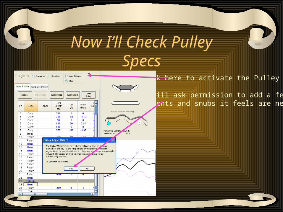
Now I’ll Check Pulley Specs
Click here to activate the Pulley Wizard
It will ask permission to add a fewSegments and snubs it feels are needed.

It adds short flights between pulleys

Going Into the Wizard It Allows Me to View My First Pulley
When I’m doneHere I can clickNext to move onTo the nextpulley

The Wizards Coordinate System
T1 is the incomingBelt direction
T2 is the outgoingBelt direction
0 direction is theForward directionFor material
These values in bold orange are program calculated but can be replaced by user

The Left Side Determines Incoming and Outgoing Belt
Directions
A 575 foot section going down hill at just shy of 5 degreesComes into the pulley
The return side goes 575 feet up hill.

Moving onto the Drive Pulley Area Does Not Look Good
I’d like to see thisMess a little better
Left click in the viewField and then useThe center scroll toZoom in.

Our First Bend is Doing Nothing
Note that the pulleyUnder currentReview is Yellow
Note that right nowOur yellow bendPulley isDo little more thanTouching the belt

OK – Time Out – What is a Wrap Angle?
It is the angle over which the belt is in contact withThe pulley.

My Miracle Correction
First I lower the position atWhich the belt comes intoThe bend pulley (the valueWas 0, now it is -5).
My reason for doing this isTo provide room for theMotor drive to run withoutPlowing into the carryingBelt overhead.
Note all of this moved down.

My Next StepI reversed the direction of pulleyRotation from counter clockwiseTo clockwise.
Note that this made the beltWrap 180 degrees around thePulley – although why a beltWould reverse direction andPull away from a pulley in mid-Air is a mystery of physics.
Note – the driveMoved up into theSpace I provided.

For My Next TrickI next reverse theDirection of the beltAs it exits my bendPulley. It was -3,Now it is 5.
(Note that the positiveDirection is the wayThe load is moving onThe carry side).

Now I Will Try to Increase Contact on My Drive Pulley
I will make the beltLeave my bend pulleyOn a downwardTrajectory {it was 0Now it is -1} (which asYou can see increasesWrap on the drivePulley)

A Manual Correction
I added the -11.31Degree angle to theWrap angle on theBend pulley so theT2 direction wouldMatch.(I’m not really sureWhy the program didNot make thisReconciliation on itsOwn)

Time to Back Up
• Why was I so eager to increase the wrap angle around the drive belt?– The Drive Pulley is where the power of the
motor is transferred to the belt. – If the Pulley spins we won’t get much action.
• So what makes the pulley not spin?– #1 The coefficient of friction with which the
pulley grips the belt.

Standard Pulley Grip Surfaces

Oh Heavy Man
Of course the flip side of a highFriction grip on the belt is beltWear.
These are called Winged Pulleys

More Reasons for a Drive Pulley Not to Spin
• #2 – The Force with which the pulley is held against the belt.– Ya – that physics stuff about the frictional force
is the force pinning the surfaces together X the coefficient of friction

That Force Comes from T1 and T2
Oh Gosh – This is looking like StaticsAll over again.
T1 T2 The flip side of pinning theBelt tight against the pulleySurface – that means a heckOf a big T1 and T2 whichMeans if I don’t want toBreak my belt in two I needOne heck of a strong $$$Expensive belt.

Reason #3
• The length of the area over which that force and coefficient of friction is applied – ie the wrap angle.– If I lengthen the area of contact I can use less
aggressive pulley surfaces– And have lower T1 and T2– Both of which save me money and wear

After That Detour I Move to My Next Pulley
I currently have another ofThose wild miracles whereA belt floats up andContacts a pulley (which ISuspect is not really goingTo happen)
This is the Drive Pulley!

I Reverse the Direction of the Pulley
It was clockwise – now it isCounter-clockwise.
This actually looks prettyGood to me – I’ll move onTo the next pulley

Its Another Bend Pulley
Since I am happy with thisSet-up I will move on.
(Incidentally I could goThrough my pulleys inAny order using the dropDown menu)

Oh – I’ve Got Another Mess Around My Take-Up

With the Aide of My New Found Skills I Fix This

Well Moving onto the Take-Up Was Not Friendly

The Reverse Rotation Direction Trick Works Well

I Love This One – How Do I Get a 360° Wrap Around a Pulley?
Mr Wizard must haveFound one of the betterCollege frat parties inTown.

Reverse Direction

And My Tail Pulley Is Ok

Lets Top Our Design Off With Peripherals
• When I load my material– I will use skirt boards– I will also assume I have to accelerate my
material from zero spead
• I will discharge material over the end of my conveyor without use of plows or trippers– But I will use belt cleaners on the return side

Skirt Board Rule of Thumb
• Length = 2X Belt Speed / 100
• Our Belt Speed is 500– 2X5 = 10 feet

Go to My Belt Profile
Note there is a slider for me to see moreAbout my profile. I this case I amWorried about my 1000 ft initialCarry section.

I Input My Skirt Board Length
The program automatically figured out it was goingTo have to accelerate the material

Put In My Belt Cleaners on the Return Just Past
the Head

Now Its Your Turn
• Conveyor Assignment #2– Take your conveyor from assignment #1– Assume your profile is
• 500 feet up hill 5 feet• 200 feet on the level• 650 feet down 7 feet to the main line conveyor
– Input the profile and get you take-ups and drives in place
– Turn in your Belt Analyst File