design of back-streaming white neutron beam line at csns
TRANSCRIPT

Design of back-streaming white neutron beam line at CSNS
L.Y. Zhanga,b,c
, H.T. Jingb,c*
, J.Y. Tangb,c,a
, Q. Lib,c
, X. C. Ruand, J. Ren
d, C. J. Ning
b,c, Y. J.
Yub,c
, Z. X. Tan b,c
, P. C. Wangb,c
, Y. C. Heb,c
, X.Q. Wanga
aNational Synchrotron Radiation Laboratory, University of Science and Technology of China,
Anhui 230029, China bInstitute of High Energy Physics, Chinese Academy of Sciences (CAS), Beijing 100049,China
cDongguan Neutron Science Center, Dongguan 523803,China
dChina Institute of Atomic Energy, Beijing 102413, China
Abstract: A white neutron beam line using back-streaming neutrons from the
spallation target is under construction at China Spallation Neutron Source (CSNS).
Different spectrometers, to be installed in the so-called Back-n beam line for nuclear
data measurements, are also being developed in phases. The physical design of the
beam line is carried out with the help of a complicated collimation system and a
sophisticated neutron dump, taking the overview of the neutron beam characteristics
into account. This includes energy spectrum, flux and time structure, the
optimizations of neutron beam spots and in-hall background. The wide neutron energy
range of 1 eV–100 MeV is excellent for supporting different applications, especially
nuclear data measurements. At Endstation#2, which is about 80 m away from the
target, the main properties of the beam line include neutron flux of 106 n/cm
2/s, time
resolution of a few per mille over nearly the entire energy range, and in-hall
background of about 0.01 /cm2/s for both neutron and gamma. With its first
commission in late 2017, Back-n will not only be the first high-performance white
neutron source in China, but also one of the best white neutron sources in the world.
Keywords: back-streaming white neutrons, time-of-flight (TOF) method, neutron
characteristics, neutron beam collimation, neutron and gamma background
1. Introduction
Complete nuclear data of good quality is very important for nuclear science and
nuclear technology applications, such as designs and analyses of accelerator-driven
subcritical systems, new-generation reactors, and nuclear medicine. At the same time,
it is also required to solve some fundamental questions in nuclear physics and nuclear
astrophysics. New generation white neutron sources, which are often associated with
spallation neutron sources, can provide high neutron flux, very wide energy range and
excellent energy resolution. Therefore, it opens new possibilities for high-precision
cross section measurements. In recent years, several international neutron nuclear
databases have gained rapid growth with the development of neutron sources,
corresponding detectors and experimental technologies.
Apart from some single-energy accelerator-based neutron sources and thermal
neutron sources from reactors, there are several white neutron sources in the world
that are devoted to carry out neutron cross section measurements, e.g., n_TOF at the

European Organization for Nuclear Research (CERN), Weapons Neutron Research
Facility (WNR) at Los Alamos Neutron Science Centre (LANSCE), Geel Electron
Linear Accelerator (GELINA) at the Institute for Reference Materials and
Measurements / Joint Research Centre (IRMM/JRC), and the Gaerttner LINAC
Center at Rensselaer Polytechnic Institute (RPI) [1]. These facilities have specific
characteristics of neutron beam intensities, energy resolutions, associated
instrumentation and data acquisition systems, and dedicated experimental programs.
The CERN n_TOF provides an intense pulsed neutron beam in a wide energy
spectrum and a good energy resolution with a time-of-flight (TOF) distance of 185 m
that stands today among the world’s leading facilities for measuring neutron-induced
cross section [2-3]. The LANSCE/WNR provides a continuous intense neutron beam
with energy ranging from about 0.1 MeV to more than 600 MeV using the 800-MeV
proton beam from the LANSCE linac and has six flight paths instrumented for a
variety of measurements [4]. GELINA has an excellent neutron energy resolution for
its short pulsed electron beam and long neutron flight path that ranges up to 400 m [5].
The RPI neutron source employs an electron Linear Accelerator (LINAC) with
electron beam energy of 60 MeV to produce short neutron beam and its neutron
measurement capability can cover an energy range from 0.005 eV to 20 MeV [6, 7].
China Spallation Neutron Source (CSNS), which is still under construction and
expected to be completed in early 2018, is developed mainly for multidisciplinary
research on material characterization by using neutron scattering techniques [8].
However, other kinds of applications at CSNS have also been planned and some of
them have gained support from different resources. The Back-n project, which utilizes
the back-streaming neutrons to build a white neutron source primarily for nuclear data
measurements, has entered the construction since 2013 [9]. The white neutron beam is
generated at the spallation target by a proton beam of 1.6 GeV and 100 kW. In this
paper, the design of the Back-n beam line, including the layout and beam optics,
energy spectrum, time resolution, and background suppression, is presented.
2. Characteristics of the back-streaming neutrons
2.1 Spallation target and proton beam line
A tantalum (0.3 mm) clad and water-cooled sliced tungsten target (11 pieces, 65
cm in total length, cross-section: 170 × 70 mm2) is being used at CSNS. The target
vessel is made of stainless steel (SS316) with a thickness of 2.5 mm for the front side,
7.5 mm for up and down sides and 12 mm for the lateral and back sides. The proton
beam spot at the target entrance is of 12 cm (H) × 4 cm (V) (four times the rms beam
size) with a quasi-uniform distribution. The interaction between the pulsed
high-energy proton beam and the heavy metal target produces a large number of
neutrons through spallation reactions. Most of the neutrons are moderated by the
target itself and three moderators, a Coupled Hydrogen Moderator, a Decoupled and
Poisoned Hydrogen Moderator, and a Decoupled Water Moderator, (see Fig. 1)
situating above and below the target. Thereafter, the moderated neutrons are
transported to 19 neutron spectrometers for neutron scattering based application.
However, there are also two white neutron beam lines in the proton beam plane: one

is the Back-n beam line and the other is a 41 forward beam line (currently sealed and
to be opened in the future) designated mainly for high-energy neutron irradiation
studies. Between the target-moderator and the biological shielding structure, there are
also reflectors of beryllium and iron to enhance the neutron utilization efficiency.
The Back-n project for nuclear data measurements is based on a previous report
which describes the characteristics of the back-streaming neutrons [10]. The first
20-m beam line of the Back-n is shared with the last section of the proton beam line –
RTBT (Ring to Target Beam Transport). A 2 mm thick aluminum alloy (A5083)
proton beam window (PBW) is located at a distance of 1.9 m from the target
separating the vacuum tube of the proton beam line and the target vessel. A copper
collimator [length: 800 mm, aperture: 200 mm (H) × 100 mm (V)], which collimates
the proton beam halo and also stops most of the back-streaming neutrons in large
divergent angles, is placed at a distance of about 2.85 m from the target. Fig. 1 shows
the geometry of the target area [11].
Fig. 1 Geometry of target-moderator-reflector (TMR) model
2.2 Neutron energy spectrum
The production, moderation, and transport of neutrons in the tungsten target have
been simulated by using FLUKA code [12-13]. The simulation also takes the PBW
into account. The energy spectra are slightly different at different locations in
low-energy region because of the large scattering effect in target station. However,
when the distance from the target surface is larger than 10 m, the energy spectra are
similar. The simulated back-streaming neutron spectra at three important locations are
shown in Fig. 2. The spectrum has a very wide energy-range, from the thermal
neutron energy to several hundred MeV, and with a peak near 1 MeV, which is usually
suitable for nuclear data measurements.

10-9
10-8
10-7
10-6
10-5
10-4
10-3
10-2
10-1
100
101
102
10-3
10-2
10-1
100
No
rma
lize
d in
ten
sity/leth
arg
y (
n/S
r/pro
ton)
Neutron energy (MeV)
at proton beam window
at 10 m from the target
at neutron beam window
Fig. 2 Back-streaming neutron energy spectrum from the CSNS target
2.3 Time resolution and CSNS operation modes
Time resolution is a key parameter in the TOF method to determine neutron
energy in a pulsed neutron source. Time resolution at Back-n will be affected by four
main factors: 1) proton beam pulse structure defined by the accelerator; 2) neutron
time expansion in the target where the neutrons are produced and moderated; 3) flight
distance from the target to the neutron detector; 4) time error in neutron detection. The
factors 2) and 3), mentioned above, are almost defined by the current CSNS target
structure and Back-n layout. Factor 4) is strongly dependent on the type of the
detector or spectrometer, and is not considered as part of the properties of a neutron
beam line. Therefore, one can design special accelerator operation mode to shorten
the proton pulse width and improve the time resolution of neutron measurement. We
have developed different accelerator operation modes for this purpose, for example: 1)
Normal Mode (N-mode): each proton pulse has two 13 ns-width (rms) bunches and
are separated by 410 ns; 2) Dedicated Mode 1 (D-mode 1): only one bunch is kept in
a proton pulse and the proton beam power is also halved; 3) Dedicated Mode 2
(D-mode 2): one bunch is used, but the rms bunch length is much reduced to only 1.5
ns, and the proton beam power is only 15% of the N-mode. The intrinsic neutron time
resolution (factors 1)-3)) can be calculated by Monte Carlo simulations. On the other
hand, it is found that for energy higher than 10 keV, the neutrons from two different
proton bunches can be distinguished [10]. Thus, the de-convolution of neutrons seems
to be possible. If the method is accomplished, the time resolution for higher-energy
neutrons (>10 keV) at the N-mode will follow that of the D-mode 1. The simulated
time resolutions at different operation modes are shown in Fig. 3. They indicate that
the time resolution is better than 1% for the whole energy range of 1 eV – 100 MeV

with the D-mode 2 and it is comparable with n-TOF for neutron’s energy higher than
100 keV.
100
101
102
103
104
105
106
107
108
0.1
1
10
Tim
e r
esolu
tion (
%)
Neutron energy (eV)
CERN n_TOF
CSNS N-mode
CSNS D-mode1
CSNS D-mode2
Fig. 3 Time resolution comparison between CERN n-TOF and CSNS Back-n on different
modes at 80 m
3. Layout of the Back-n beam line and neutron collimation
3.1 Layout design
The back-streaming neutrons emitting from the spallation target are transported
in an 80-m long vacuum pipe along the reverse direction of incident proton beam. The
first 20-m channel is common for both the proton and the neutron beam. At about 20
m from the target, a bending magnet which separates the proton and neutron beam can
sweep off the charged particles contaminated in the neutron beam, and a shielding
concrete wall at a distance of 24 m separates this high-radiation area from other parts
of the tunnel. After the shielding wall, the first component in the Back-n beam line is
a neutron beam window (NBW). Along the flight path, one neutron shutter (also
functions as a collimator) and two collimators are used to control the neutron beam
intensity and beam spot sizes, which are discussed in detail in the next section. At
about 56 m and 76 m from the spallation target, two endstations (ES#1 & ES#2) will
host seven detector systems (or spectrometers) in total. However, with only one set of
them will be used in a time for experiments. ES#1 and ES#2 are used for high-flux
and high-resolution experiments, respectively. A preparation room is allocated for
experiments and temporal storage of detectors. Moreover, there is a dedicated Back-n
control room in the RTBT building which is just above the ES#2. Due to limited space,
an in-room and complex neutron dump is located at the rear side of ES#2. In order to
suppress the background neutrons and gammas efficiently, several thick concrete
walls and inner bushings with boron-containing polyethylene are set along the flight
tunnel. Fig. 4 shows the layout of the Back-n beam line, and the distances of key
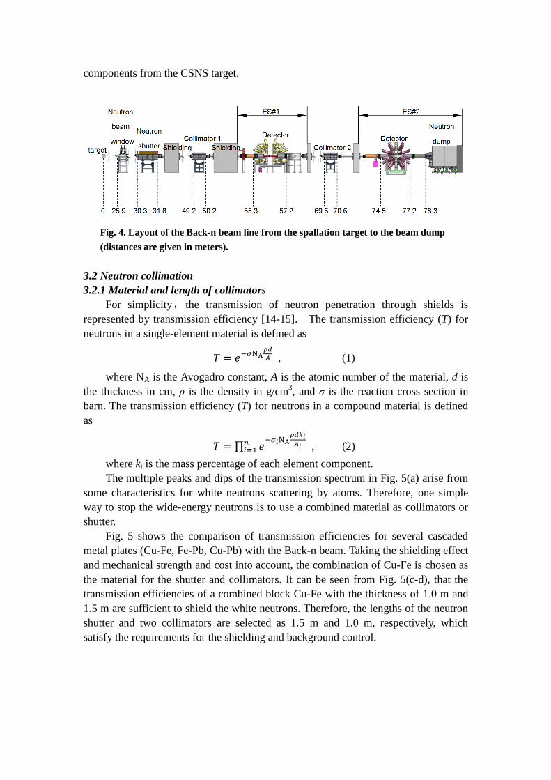
components from the CSNS target.
Fig. 4. Layout of the Back-n beam line from the spallation target to the beam dump
(distances are given in meters).
3.2 Neutron collimation
3.2.1 Material and length of collimators
For simplicity, the transmission of neutron penetration through shields is
represented by transmission efficiency [14-15]. The transmission efficiency (T) for
neutrons in a single-element material is defined as
, (1)
where NA is the Avogadro constant, A is the atomic number of the material, d is
the thickness in cm, ρ is the density in g/cm3, and σ is the reaction cross section in
barn. The transmission efficiency (T) for neutrons in a compound material is defined
as
, (2)
where ki is the mass percentage of each element component.
The multiple peaks and dips of the transmission spectrum in Fig. 5(a) arise from
some characteristics for white neutrons scattering by atoms. Therefore, one simple
way to stop the wide-energy neutrons is to use a combined material as collimators or
shutter.
Fig. 5 shows the comparison of transmission efficiencies for several cascaded
metal plates (Cu-Fe, Fe-Pb, Cu-Pb) with the Back-n beam. Taking the shielding effect
and mechanical strength and cost into account, the combination of Cu-Fe is chosen as
the material for the shutter and collimators. It can be seen from Fig. 5(c-d), that the
transmission efficiencies of a combined block Cu-Fe with the thickness of 1.0 m and
1.5 m are sufficient to shield the white neutrons. Therefore, the lengths of the neutron
shutter and two collimators are selected as 1.5 m and 1.0 m, respectively, which
satisfy the requirements for the shielding and background control.

103
104
105
106
107
0.0
0.1
0.2
0.3
0.4
0.5
0.6
0.7
0.8
103
104
105
106
107
108
10-13
10-11
10-9
10-7
10-5
10-3
10-1
103
104
105
106
107
0.00
0.04
0.08
0.12
0.16
103
104
105
106
107
108
10-20
10-18
10-16
10-14
10-12
10-10
10-8
10-6
Tra
nsm
issio
n e
ffic
iencie
s Cu(20 cm)
Fe(20 cm)
Pb(20 cm)
(a)
Tra
nsm
issio
n e
ffic
ien
cie
s Cu(70 cm)+Fe(30 cm)
Fe(70 cm)+Pb(30 cm)
Cu(70 cm)+Pb(30 cm)
(c)
Tra
nsm
issio
n e
ffic
iencie
s
Neutron energy (eV)
Cu(10 cm)+Fe(10 cm)
Fe(10 cm)+Pb(10 cm)
Cu(10 cm)+Pb(10 cm)
(b)
Tra
nsm
issio
n e
ffic
iencie
s
Neutron energy (eV)
Cu(120 cm)+Fe(30 cm)
Fe(120 cm)+Pb(30 cm)
Cu(120 cm)+Pb(30 cm)
(d)
Fig. 5 Comparison of the transmission efficiencies for different thickness and material
combinations with a white neutron beam
3.2.2 Neutron optics
According to the requirements of different experiments, three beam-spot settings,
30 mm, 60 mm and 90 mm × 90 mm, are designed at ES#2. In order to provide
sharp profiles and reduce the background, a multi-stage collimation system has been
used. The three collimators of different remote-controlled apertures, each followed by
a shielding wall, are placed at the NBW before ES#1 and ES#2, as shown in Fig. 4. In
order to save space and cost, the first collimator is also used as a shutter to stop
neutrons from entering the endstations when a blank aperture is used.
A simplified optical schematic of neutrons is shown in Fig. 6. The neutron
optical lines 1, 2 and 3 define the beam spot size, beam spot core and beam intensity,
respectively. The shutter and Collimator 2 act as main collimators to control beam
intensity and beam spot size. As an auxiliary collimator, Collimator 1 is used to
reduce the beam halo and the background. The spot sizes at ES#1 are determined by
the aperture setting of the shutter and Collimator 1 by following that of ES#2 in a
passive manner.

Fig. 6 A simplified depiction of the neutron beam optics
For the nominal beam spot of Φ30 mm at ES#2, the size of beam spot is smaller
than the proton beam spot at the target. The shutter and Collimator 2 can easily define
the beam spot according to line 1. In order to get a better beam uniformity, the shutter
aperture can be increased slightly. On the other hand, optimization of the collimator
apertures has an important influence on both beam intensity and uniformity.
Collimator 1 is important to control the beam halo in practical cases. According to the
optical relation, the aperture range of Collimator 1 can be defined by line 2 and 3.
Thus the aperture setting for the three collimators can be determined. The nominal
beam spot sizes of Φ60 mm and 90 mm × 90 mm are bigger in the vertical direction
than the height of proton beam spot (40 mm) at target. Thus the neutron optics is
slightly different as the target size also plays a role here. However, the beam halo and
neutron background are also important for many experiments, and they also affect the
optimization of the collimator apertures as discussed in the next sub-sections. Based
on the optical results and the practical collimator designs, the three sets of collimation
apertures together with the beam intensities are given in Table 1.
Table 1 Back-n neutron beam spots & fluxes and corresponding collimation aperture
parameters (@100 kW)
ES#2 spot
(mm)
Shutter
(mm)
Coll#1
(mm)
Coll#2
(mm)
ES#1 spot
(mm)
ES#1 flux
(/cm2/s)
ES#2 flux
(/cm2/s)
Foreseen
experiments
30 12 15 40 20 2.20×10⁶
7.81×10⁵
(n, t), (n,), (n,
n’), (n,2n)
60 50 50 58 50 4.33×10⁷ 1.36×10
7
(n, f), (n, lcp),
PFNS
90×90 78×62 76×76 90×90 75×50 5.98×10⁷ 2.18×10
7
neutron
radiography
3.2.3 Simulations of collimation
The most important components of collimation along the neutron flight path are
the neutron shutter (also functions as a collimator) and the two collimators. Following
the optical design, the optimization of the collimators has been carried out by
multi-particle simulations. Due to very long flight path of 80 m, a secondary sampling

of the neutron beam at the NBW has been used to save simulation time. In addition, to
help find a first approximate solution, the simulations are started with black-body
material for collimators and ducts. The black-body assumption is just limited to firstly
study the relations between collimator aperture size and beam uniformity and intensity.
And then many simulations and optimizations with more realistic conditions are
followed.
In order to find balanced designs for beam intensity and uniformity for the given
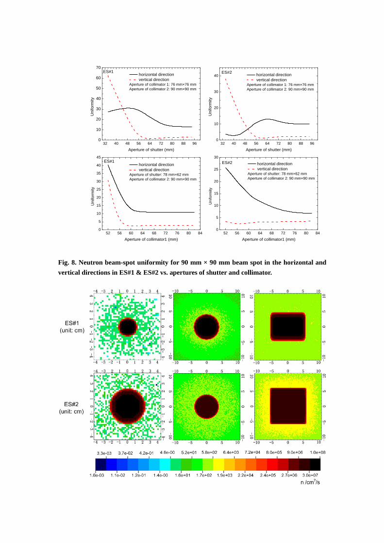
spot sizes, many aperture combinations have been used. For example, Fig. 7 shows
the beam intensity dependence on the shutter aperture, and Fig. 8 shows the
uniformity dependence on the shutter and collimator apertures. The uniformity is
defined as the relative change of the beam intensity at the beam center (Icenter) to that
at the beam edge (Iedge) (
). It can be seen that the uniformity
has different trends with respect to apertures in the horizontal and vertical directions
because of the asymmetry of the proton beam spot. Fig. 9 shows the neutron
distributions for the three beam spots in the experimental halls, using the aperture
settings of Table 1.
30 35 40 45 50 55 60 65 70 75 80 85 90 95 1000.00
0.05
0.10
0.15
0.20
0.25
Norm
aliz
ed Inte
nsity
Aperture of shutter (mm)
ES#1
ES#2
90mm×90mm
Fig. 7 Neutron intensities of two endstations vs. shutter aperture by fixing the apertures of
Collimator 1 & 2 (76 mm & 90 mm, respectively).
32 40 48 56 64 72 80 88 960
10
20
30
40
50
60
70
32 40 48 56 64 72 80 88 960
10
20
30
40
52 56 60 64 68 72 76 80 840
5
10
15
20
25
30
35
40
45
52 56 60 64 68 72 76 80 840
5
10
15
20
25
30
Un
ifo
rmity
Aperture of shutter (mm)
horizontal direction
vertical directionAperture of collimator 1: 76 mm×76 mm
Aperture of collimator 2: 90 mm×90 mm
ES#1
Un
ifo
rmity
Aperture of shutter (mm)
horizontal direction
vertical directionAperture of collimator 1: 76 mm×76 mm
Aperture of collimator 2: 90 mm×90 mm
ES#2
Un
ifo
rmity
Aperture of collimator1 (mm)
horizontal direction
vertical directionAperture of shutter: 78 mm×62 mm
Aperture of collimator 2: 90 mm×90 mm
ES#1
Un
ifo
rmity
Aperture of collimator1 (mm)
horizontal direction
vertical directionAperture of shutter: 78 mm×62 mm
Aperture of collimator 2: 90 mm×90 mm
ES#2
Fig. 8. Neutron beam-spot uniformity for 90 mm × 90 mm beam spot in the horizontal and
vertical directions in ES#1 & ES#2 vs. apertures of shutter and collimator.

Fig. 9 Neutron density distribution for three cases at ES#1 & ES#2 (From left to right: 30
mm, 60 mm, 90 mm × 90 mm).
4. Background at the experimental halls
For nuclear data measurements at a white neutron source, it is an important issue
to control the background at the experimental endstations. The background includes
gammas, neutrons and charged particles. As mentioned before, the charged particles at
the Back-n are well suppressed by the 15 bending magnet in the RTBT beam line.
Therefore, only gamma and neutron backgrounds are a matter of concern here. They
mainly arise from the proton beam loss in the nearby RTBT and spallation target,
leakage of the collimators and dump, and also from spectrometers. The experiment
related background varies with individual experimental setup and is not discussed in
this paper. As the beam spot of 90 mm 90 mm is mainly used for neutron imaging,
the background is much less important for nuclear data measurements. Table 2 shows
the contribution of different main source terms to the experimental hall backgrounds.
Table 2 Background in the experimental halls for the beam spot of 30 mm (fluence out/in
beam, @100 kW)
Background source Background at ES#1 Background at ES#2
Neutron Gamma Neutron Gamma
RTBT(proton beam loss) ~10-7
~10-7
Negligible Negligible
Target/collimators/pipe ~10-6
~10-6
~10-8
~10-8
Neutron dump Negligible Negligible ~10-9
~10-9
4.1 From proton beam loss
The proton loss in the nearby RTBT tunnel will produce many neutrons and
gammas. A part of high-energy neutrons will leak into the experimental hall through
the shielding wall which separates the two tunnels. Although primary gammas can be
stopped by the shielding wall, secondary gammas will be produced concomitantly by
neutrons.
In order to suppress the neutrons penetrating the shielding wall, the first step is to
insert an 80 cm thick iron block in the 2-m thick concrete shielding wall in the section
separating ES#1. Thereafter, the usual requirement of 1 W/m for beam loss in the
RTBT is reduced to 0.1 W/m in this special section, and this can be achieved as the
RTBT section is a straight section composed of simple periodic focusing transport
units. Moreover, a wall-cloth suit of 5-cm thick boron-containing polythene is
installed on the four walls and ceil at ES#1. The neutron and gamma backgrounds in
the experimental halls by the proton beam loss are simulated by FLUKA. A uniformly
distributed line-type loss source of 0.1 W/m in RTBT is assumed and the neutron and
gamma fluence distributions are shown in Fig. 10. With these actions, both the
neutron and gamma backgrounds can be suppressed to an acceptable level at ES#1,
whereas the background contribution at ES#2 from proton loss is totally negligible.

Fig. 10 Neutron & gamma backgrounds in the ES#1 experimental hall. The dotted line
represents the line-type proton loss source.
4.2 From incoming neutrons
On their way to the endstations, the back-streaming neutrons and gammas pass
through the NBW, shutter, collimators and shielding walls along the neutron beam
line, and produce scattered neutrons and gammas. Obviously, this part of the
background contribution is complicated and can be classified as follows: (1) neutrons
and gammas due to leakage from the collimators and front shield wall (2) scattered
neutrons from the inner surface of the collimators and beam tubes (3) secondary
gammas produced by neutrons interacting with shielding walls and (4) original
gamma flash from the spallation target, which can be distinguished from the neutron
burst by its early arrival at the endstations and its detection in the upstream beam line
can be employed as the T0 signal for the TOF method. Fig. 11 shows the neutron and

gamma backgrounds for three beam spots in the two endstations, simulated by
FLUKA. In addition, with the help of inner bushings of boron-containing
polyethylene in the shielding walls, the backgrounds in the experimental endstations
can also be suppressed. For example, for the beam spot of 30 mm, the background is
lower than the neutron beam flux by ~107–10
8 at ES#1and ES#2.

10-1
101
103
105
107
-300 -200 -100 0 100 200 30010
-3
10-1
101
103
105
107
ES#1
30 mm
60 mm
90 mm×90 mm
(b)
Neu
tron inte
nsity (
n/c
m2/s
)
Distance from beam center (cm)
ES#2
30 mm
60 mm
90 mm×90 mm
Fig. 11 Neutron beams and backgrounds at 100 kW: (a) Neutron & gamma fluences (From
up to down: 30 mm, 60 mm, 90 mm × 90 mm); (b) and neutron profiles at ES#1 and
ES#2
4.3 From neutron dump
Due to the space limitation of the CSNS layout, the neutron dump needs to be
placed at the rear side of the ES#2. The backscattered and leaked neutrons and
secondary gammas from the dump will contribute to the ES#2 backgrounds. In order
to suppress this part of background, a sophisticated in-room compact dump has been
designed [16]. For this study, the neutron beam is sampled again in FLUKA at the
dump entrance. Fig. 12 shows the neutron background due to dump in the ES#2
experimental hall. The off-beam background is about 10-8
, relative to the neutron flux
for the small beam spot of 30 mm. The in-beam background is about three orders of
magnitude higher than the off-beam background. The gamma background is almost
equivalent to that of the neutron. For the other two cases, the backgrounds meet the
experimental requirements.

Fig. 12 Neutron backgrounds from the dump contribution in the ES#2 hall for three neutron
beam spots

5. Key device designs
5.1 Neutron beam window
NBW is located at a distance of 26 m from the target, which separates the
vacuum conditions between the proton beam line (10-6
Pa) and neutron beam line
(10-4
Pa) and also allows riskier vacuum down in the neutron beam line. For the
window material, it is important that it produces as little distortion as possible to the
energy spectrum shape and to beam intensity. In Fig. 13, several window materials are
compared by using the energy-dependent transmission efficiencies in the whole
neutron energy range. Finally, aluminum alloy A5083 of 1 mm thickness has been
chosen for its good mechanical and neutron transmission properties. An additional
advantage is that this material is also used for the proton beam window. A double
spherical shape allows the thin window to stand for 1-atm pressure. At the same time,
in the same vacuum chamber, a remote-controlled Cd filter and/or another filter can
be inserted into the beam path as a low-energy (<1 eV) neutron absorber or for
in-beam background measurement.
10-5
10-4
10-3
10-2
10-1
100
101
102
103
104
105
106
107
108
0.2
0.3
0.4
0.5
0.6
0.7
0.8
0.9
1.0
MylarTi
Fe
Be
Tra
nsm
issio
n e
ffic
ien
cie
s
Neutron energy (eV)
1 mm Al
1 mm A5083
1 mm A6061
0.5 mm Mylar
1 mm Be
1 mm Ti
1 mm Fe
A6061
Fig. 13 Comparison of the transmission efficiencies for different materials in the whole
neutron energy range
5.2 Neutron beam shutter
The neutron shutter is located at a distance 31 m from the target. The shielding
block is housed in a coffin-like vacuum chamber, and the block size is 1500 mm
(length) × 150 mm (height) × 600 mm (width). As mentioned earlier, a combined

material of 1.2-m copper and 0.3-m iron is used for better stopping of neutrons. Five
positions in the horizontal direction are important for the remote-controlled shutter
function: one blank position to stop neutrons, three apertures as the primary
collimator for main experiments and a very small aperture of 3 mm for special low
intensity applications. Magnetic fluid seal is used for mechanical motion in vacuum to
shorten the lateral dimension. The shutter is also used as the key device in the
radiation safety control.
5.3 Collimators
The two collimators are located before the two experimental endstations,
followed by shielding walls. They have similar shutter structure, but with shorter
length of 1 m or 0.7 m copper and 0.3 m iron. They require only three positions in the
horizontal direction to design the collimation apertures. The two collimators are of
slightly different dimensions: 1000 mm (length) × 150 mm (height) × 375 mm (width)
for Collimator 1, 1000 mm (length) × 150 mm (height) × 385 mm (width) for
Collimator 2.
5.4 Neutron dump
Due to general CSNS layout constraints, the neutron dump has to be placed
inside the ES#2. In order to minimize its background contribution in the ES#2 hall, a
sophisticated dump has been designed [16], as shown in Fig. 14. Copper and iron are
used for stopping fast neutrons, boron polyethylene and lead shell absorb slow
neutrons and secondary gammas respectively, and the cone-shape boron-polyethylene
enclosing the incoming beam duct reduces the back-scattered neutrons. There are also
three sets of changeable bushings in boron-polyethylene, corresponding to three beam
spots, in the end section of the vacuum beam duct.
Fig. 14 Geometry structure of the neutron dump.
6. Conclusions
The back-streaming white neutron beam line at CSNS is being constructed for
nuclear cross-section measurements. In addition to the simulation and analysis of the

neutron energy spectrum and time resolution, the beam line design including optical
design, neutron beam profile shaping and neutron/gamma background simulations is
based on FLUKA Monte Carlo simulations. The simulations, which were carried out
in the most realistic conditions achievable, show that the beam characteristics and
backgrounds meet the design requirements of the Back-n layout and are very much
suitable for nuclear data measurements. Some technical design aspects of the key
elements are also discussed.
The main components of the beam line are under installation, and four detector
systems are simultaneously under construction. The first batch of experiments or
day-one experiments on nuclear data measurements are expected to be conducted
from late 2017 to early 2018.
Acknowledgements
This work was supported by the National Key Research and Development
Program of China (Project: 2016YFA0401600), National Natural Science Foundation
of China (Project 11235012), the CSNS Engineering Project and Opening Special
Foundation of State Key Laboratory of Intense Pulsed Radiation Simulation and
Effect (Project number SKLIPR.1517). The authors would like to thank the colleagues
of the CSNS white neutron source collaboration for discussions.
References
[1] Bartholomew K. M., et al. Compendium of Neutron Beam Facilities for High Precision
Nuclear Data Measurements. IAEA-TECDOC series, ISSN 1011-4289, no. 1743
[2] C. Guerrero, et al. Performance of the neutron time-of-flight facility n_TOF at CERN. Eur.
Phys. J. A (2013) 49: 27
[3] C. Weib, et al. The new vertical neutron beam line at the CERN n_TOF facility design and
outlook on the performance. Nucl. Inst. and Meth. A, 799 (2015) pp.90–98
[4] Lisowski P W, Schoenberg K F. The Los Alamos neutron science center. Nucl. Inst. and Meth.
A, 562(2006) pp.910−914
[5] W. Mondelaers, P. Schillebeeckx. GELINA, a neutron time-of-flight facility for high-resolution
neutron data measurements. Notiziario Neutroni e Luce di Sincrotrone, Research
Infrastructures vol. II no. 2 p. 19-25 (2006)
[6] Y. Danon, R.C. Block, R. Bahran, M. Rapp, F. Saglime, C. Romano, J. Thompson, D.P. Barry,
N.J. Drindak, J. Hoole, G. Leinweber, “Nuclear Data Measurements at the RPI LINAC”,
Proceedings of The Eighth International Topical Meeting on Nuclear Applications and
Utilization of Accelerators (AccApp07), Pocatello Idaho, July 30 – August 2, 2007.
[7] Y. Danon, L. Liu, E.J. Blain et al., Transactions of the American Nuclear Society, Vol. 109,
Washington, D.C., November 10–14, 2013
[8] J. Wei, et al. China spallation neutron source: design, R&D, and outlook. Nucl. Inst. and Meth.
A, 600 (2009) pp.10–13
[9] TANG Jing-Yu, JING Han-Tao, XIA Hai-Hong, et al. Key Nuclear Data Measurements for
Advanced Fission Energy and White Neutron Source at CSNS. Atomic Energy Science and
Technology, Vol. 47, No. 7, (2013) pp. 1089-1095 (in Chinese)

[10] H.T. Jing, et al. Studies of back-streaming white neutrons at CSNS. Nucl. Inst. and Meth. A,
621 (2010) pp.91–96
[11] Tianjiao Liang, Wen Yin, Quanzhi Yu, et al. “Progress of CSNS Neutronics works”[R]. The
6th CSNS Neutron Technology Advisory Committee, Dec. 14, 2014
[12] A. Ferrari, P.R. Sala, A. Fasso, J. Ranft, FLUKA: a multi-particle transport code,
CERN 2005-10,INFN/TC-05/11,SLAC-R-773,2005
[13] G. Battistoni, S. Muraro, P.R. Sala, F. Cerutti, A. Ferrari, S. Roesler, A. Fasso,
J. Ranft, The FLUKA code: description and benchmarking, in: M. Albrow, R.
Raja (Eds.), Proceedings of the Hadronic Shower Simulation Workshop 2006,
Fermilab 6–8 September 2006, AIP Conf. Proc. 896, (2007), pp.31–49
[14] J.K. Shultis, R.E. Faw. Radiation shielding and radiological protection: Handbook of nuclear
engineering. Springer (2010) pp.1376-1478
[15] XIE Zhong-sheng, Wu Hong-chun, Zhang Shao-hong. Nuclear reactor physical analysis[M].
Xi'an Jiaotong University press and Atomic Energy press, in 2004, pp.8-11
[16] L.Y. Zhang, H.T. Jing, J.Y. Tang, X.Q. Wang. Design and simulations of the neutron dump for
the back-streaming white neutron beam at CSNS. Radiation Physics and Chemistry 127, 133
(2016)