design of an improved grey water recycling...
TRANSCRIPT
UNIVERSITY OF NAIROBI
SCHOOL OF ENGINEERING
DEPARTMENT OF ENVIRONMENTAL AND BIOSYSTEMS
ENGINEERING
ENGINEERING DESIGN PROJECT
DESIGN OF AN IMPROVED GREY WATER RECYCLING
SYSTEM
NAME : MOGAKA ALPHAS OMBESE
REG NO : F21/0031/2008
SUPERVISOR: ENG. S.C ONDIEKI
Report submitted in partial fulfilment for the requirements for the degree of Bachelor
of Science in Environmental and Biosystems Engineering.
APRIL 2013

ii
DECLARATION
This project is my work and has not been presented for any degree in any other
university.
SIGNATURE DATE
MOGAKA ALPHAS OMBESE
STUDENT
This project has been submitted for the examination with my approval.
SIGNATURE DATE
ENG. S C ONDIEKI
SUPERVISOR

iii
ABSTRACT
Students residing in Mugabe Hostel of the College of Agriculture and Veterinary
Services of the University of Nairobi have been plagued with inconsistent supply of
water to the halls of residence. Sanitation has been greatly hampered due to this
especially in the toiletry section.
This project proposes a grey water recycling system that will provide recycled
water specifically for flushing the lavatories. The grey water recycling system
components are designed and they consist of: Diversion system, piping system,
filtration system, storage system and the pumping system. They various systems
were tested on the EPANET software and it proved successful.
The study begins with the introduction and objectives and the literature review
together with the theoretical frame work highlighted. The methodology, data
collected, results and analysis are discussed within. Finally, the conclusions
recommendation and design drawings are provided.
The findings of the project are compiled in this report.

iv
ACKNOWLEDGEMENTS
This project completion has been made possible with the assistance of a
number of persons to whom I would like to express my sincere gratitude.
I am indebted to my supervisors Eng. S. C Ondieki for his continued guidance,
suggestions, comments and encouragement throughout the period and
completion of this study.
I would also like to express my gratitude to the Maintenance manager and his
staff for the assistance they afforded me during the study.
Finally, I owe special thanks to my family for their encouragement and moral
support. Thank you all for your prayers.
MAY GOD BLESS YOU ALL

v
Table of Contents DECLARATION ............................................................................................................................................... ii
ABSTRACT ..................................................................................................................................................... iii
ACKNOWLEDGEMENTS ................................................................................................................................ iv
LIST OF FIGURES ......................................................................................................................................... viii
LIST OF TABLES ............................................................................................................................................. ix
1. INTRODUCTION ..................................................................................................................................... 1
1.1. Background Information ............................................................................................................... 1
1.2. Problem Statement ....................................................................................................................... 1
1.2.1. Project Justification ................................................................................................................... 2
1.2.2. Problem Analysis ....................................................................................................................... 2
1.3. Site Analysis and Inventory ........................................................................................................... 2
1.4. Objectives...................................................................................................................................... 3
1.4.1. Specific Objectives .................................................................................................................... 3
1.5. Statement of Scope ....................................................................................................................... 3
2. LITERATURE REVIEW ............................................................................................................................. 4
2.1. Grey Water .................................................................................................................................... 4
2.2. Potential of Greywater Reuse ....................................................................................................... 5
2.3. Benefits of Grey Water recycling .................................................................................................. 6
2.4. Quantification of grey water ......................................................................................................... 7
2.5. Direct Method ............................................................................................................................... 8
2.6. Indirect Method ............................................................................................................................ 9
2.7. Components of Greywater Treatment Systems ........................................................................... 9
2.8. Components of Greywater Treatment Systems ......................................................................... 10
2.8.1. Diversion System ..................................................................................................................... 10
2.8.2. Piping system .......................................................................................................................... 10
2.8.3. Filtration unit .......................................................................................................................... 10
2.8.3.1. Upflow-downflow filter ................................................................................................... 11
2.8.3.2. Multi-media filter ............................................................................................................ 11
2.8.3.3. Slow sand filter ................................................................................................................ 11
2.8.3.4. Horizontal Roughing Filter .............................................................................................. 12
2.8.4. Delivery and Storage System .................................................................................................. 13

vi
2.8.5. Pumping Unit .......................................................................................................................... 13
3. THEORETICAL FRAMEWORK ............................................................................................................... 14
3.1. Grey Water .................................................................................................................................. 14
3.2. Biochemical Oxygen Demand (BOD) ........................................................................................... 14
3.3. Site Selection ............................................................................................................................... 15
3.4. Head loss ..................................................................................................................................... 15
3.5. The Pump characteristics ............................................................................................................ 16
3.6. Sizing of conveyance pipes ......................................................................................................... 17
3.7. Design of storage tank ................................................................................................................ 18
3.8. Tank Loadings .............................................................................................................................. 20
4. GENERATION OF CONCEPT DESIGN .................................................................................................... 21
5. METHODOLOGY .................................................................................................................................. 22
5.1. Study Area ................................................................................................................................... 22
5.1.1. Location ................................................................................................................................... 22
5.1.2. Land Cover .............................................................................................................................. 23
5.1.3. Topography ............................................................................................................................. 23
5.1.4. Water Supply System .............................................................................................................. 23
5.1.5. Waste Management................................................................................................................ 23
5.2. Data Collection ............................................................................................................................ 23
5.2.1. Water Consumption Data ....................................................................................................... 23
5.3. Design .......................................................................................................................................... 24
5.3.1. Design of the diversion system ............................................................................................... 24
5.3.2. Filtration and Treatment System ............................................................................................ 24
5.3.3. Delivery and Storage System .................................................................................................. 24
5.3.4. Overall Design Layout ............................................................................................................. 24
6. RESULTS AND ANALYSIS ...................................................................................................................... 25
6.1. Water Consumption Data ........................................................................................................... 25
6.2. Diversion System ......................................................................................................................... 27
6.2.1. Piping ....................................................................................................................................... 27
6.2.2. Junction Chamber ................................................................................................................... 27
6.3. Filtration and Treatment System ................................................................................................ 27
6.3.1. Screen ...................................................................................................................................... 27

vii
6.3.2. Equalization or Settling Tank .................................................................................................. 28
6.3.2.1. Design Criteria for an Equalization Chamber .................................................................. 28
6.3.3. Filtration Unit .......................................................................................................................... 30
Disinfection ............................................................................................................................................. 31
6.4. Collection / Storage Tank ............................................................................................................ 31
6.4.1. Material ................................................................................................................................... 32
6.4.2. Shape and Position .................................................................................................................. 32
6.4.3. Dimensions of the storage tank .............................................................................................. 33
6.5. Pumping and Piping System ........................................................................................................ 35
6.5.1. Pipes ........................................................................................................................................ 35
6.5.2. Pumps...................................................................................................................................... 35
6.6. COST BENEFIT ANALYSIS ............................................................................................................. 37
6.7. SCHEMATIC DIAGRAM OF A GREY WATER RECYCLING SYSTEM ..................................................... 38
6.8. Water Quality Monitoring ........................................................................................................... 39
6.8.1. Odour Control ......................................................................................................................... 39
6.9. Maintenance of Greywater Treatment System .......................................................................... 40
7. CONCLUSION ....................................................................................................................................... 42
8. RECOMMENDATION ........................................................................................................................... 43
9. REFERENCES ........................................................................................................................................ 44
10. APPENDICES .................................................................................................................................... 46
OBSERVATION / DATA SHEET .................................................................................................................. 46
TANK MATERIAL PROPERTIES ................................................................................................................. 48
3D VIEWS OF THE SYSTEM PARTS ........................................................................................................... 49
EQUILIZATION CHAMBER ........................................................................................................................ 51
FILTRATION UNIT .................................................................................................................................... 52
STORAGE TANK ....................................................................................................................................... 53
PUMPING SYSTEM .................................................................................................................................. 54

viii
LIST OF FIGURES
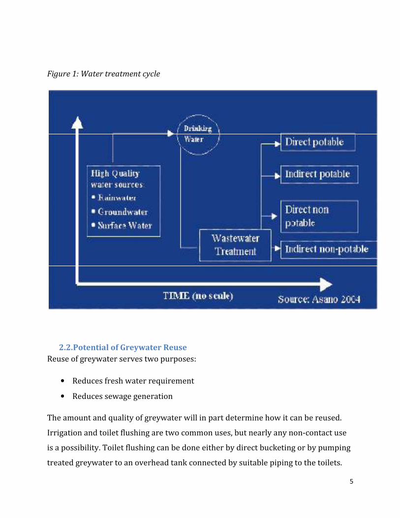
Figure 1: Water Treatment Cycle
Figure 2: Google Maps Location of Mugabe Hostel.
Figure 3: Equalization Chamber
Figure 4: Filtration Unit
Figure 5: Storage Tank
Figure 6: Pump
Figure 7: Schematic Diagram of a Grey Water Recycling System
Figure 8: Tank Material Properties
Figure 9:3D Views of the System Parts
Figure 10: Different Views of the Recycling Unit
Figure 11: Equalization Chamber
Figure 12: Filtration Unit
Figure 13: Storage Tank
Figure 14: Pumping System

ix
LIST OF TABLES
Table 1: Average Volume of Water Consumed In a Day
Table 2: Design Criteria for an Equalization Chamber
Table 3: Filtration Unit Parameter
Table 4: Pipe Sizes
Table 5: Pump Characteristics
Table 6: Observation / Data Sheet
Table 7: Summary of the System Maintenance

1. INTRODUCTION
1.1. Background Information
Water is becoming a rare resource in the world. It is therefore essential to reduce
surface and ground water use in all sectors of consumption, to substitute fresh
water with alternative water resources and to optimize water use efficiency through
reuse options.
These alternative resources include rainwater and greywater. This project will focus
on greywater treatment and its use as an alternative water resource in a students’
hostel.
Greywater is commonly defined as wastewater generated from bathroom, laundry
and kitchen. Due to rapid industrialization and development, there is an increased
opportunity for greywater reuse in developing countries such as Kenya.
Consequent to rapid growth in population and increasing water demand, stress on
water resources in Kenya is increasing and per capita water availability is reducing
day by day.
Recycling grey water for purposes of flushing toilets is therefore a viable option.
However the volume of grey water produced should be sufficient enough to warrant
such a project.
1.2. Problem Statement
Mugabe Hostel has been plagued with inconsistent water supply. This has had
severe consequences on the sanitation of the hostel, especially on the toiletry
section. Students are therefore forced to fetch water from the groundwater tanks,
ferry it to the wash rooms for their use while the toilets had no source of water. This
forced critical thinking on ways of solving this problem, hence developing a system

2
where grey water from laundry and showers can be reused to flash the toilets will
ensure a constant supply of water and freeing fresh water for better consumption.
1.2.1. Project Justification
The need to uphold sanitation standards in Mugabe Hostels has prompted critical
thinking to come up with solutions. Various ways of supplementing the existing
water supply to the hostel have been exhausted. In the recent past two boreholes
had been sunk to supplement the water deficit being experienced at the Hostel.
However, they are now trying to cover up the boreholes that had been sunk in the
area and after cleaning and testing, the water discovered has been ruled out as
unsuitable for human consumption.
This project can therefore act as a plan B to the water shortage problem if
implemented.
1.2.2. Problem Analysis
Given the large quantity of grey water being discharged from the hostel, recycling it
and using it to flush the toilet will not only ensure constant supply of water for
flushing the toilets but also effectively reduce the strain on fresh water supply i.e.
fresh water needed for flushing will be zero.
1.3. Site Analysis and Inventory
The case study for this project is based on Mugabe Hostel in the College of
Agriculture and Veterinary Sciences of the University of Nairobi. The Hostel is
located in Upper Kabete, off Waiyaki way. This is where proper sanitation is
hindered due to the inadequate water supply to the hostel. Most of the water used is
in the showers, for laundry and toilet flushing. This therefore means that once the
tanks are empty the state of the lavatories becomes dire. The system is well suited

3
since the topography of the region will allow for flow of the waste water downhill
hence the recycling process will be by gravity.
1.4. Objectives
The Overall Objective is to design a grey water recycling system for Mugabe Hostel.
1.4.1. Specific Objectives
� Determine the quantity and quality of the grey water
� Design the various system components for the grey water collection
1.5. Statement of Scope
• This project involves the design of a grey water recycling system for Mugabe
Hostel.
• Water consumption and quality evaluation will also be determined

4
2. LITERATURE REVIEW
2.1. Grey Water
Grey water is wastewater generated from domestic activities such as laundry,
bathing and dishwashing. It comprises of about two-thirds of domestic water use. It
gets its name from the cloudy appearance and from its status as neither being fresh
nor polluted (Wikipedia 2009).
Water from the toilets is sewage or black water which indicates it has fecal matter
and urine hence cannot be recycled.
Grey water is easier to treat and recycle because of the low levels of contamination.
If the grey water is harvested on a separate plumbing, the grey water can be
recycled, stored and re-used. Filtration units and microbial digestion can be used to
provide clean water for flushing toilets or even watering garden plant (Myca, 2002)
Most grey water is easier to treat and recycle than blackwater, because of lower
levels of contaminants. If collected using a separate plumbing system from
blackwater, domestic grey water can be recycled directly within the home, garden
or company and used either immediately or processed and stored. If stored, it must
be used within a very short time or it will begin to putrefy due to the organic solids
in the water. Recycled grey water of this kind is never safe to drink, but a number of
stages of filtration and microbial digestion can be used to provide water for washing
or flushing toilets. Some grey water may be applied directly from the sink to the
garden or container field, receiving further treatment from soil life and plant roots.
Given that grey water may contain nutrients, pathogens, and is often discharged
warm, it is very important to store it before use in irrigation purposes, unless it is
properly treated first. (Asano, 2004)
5
Figure 1: Water treatment cycle
2.2. Potential of Greywater Reuse
Reuse of greywater serves two purposes:
• Reduces fresh water requirement
• Reduces sewage generation
The amount and quality of greywater will in part determine how it can be reused.
Irrigation and toilet flushing are two common uses, but nearly any non-contact use
is a possibility. Toilet flushing can be done either by direct bucketing or by pumping
treated greywater to an overhead tank connected by suitable piping to the toilets.

6
The grey water recycled can be used for the following purposes.
• Toilet flushing
• Floor cleaning
• Irrigation
• Gardening
• Car washing
• Construction
2.3. Benefits of Grey Water recycling
The concept of wastewater recycling has been continuously developed and various
benefits have arisen due to the recycled water. They include:
� Lower fresh water extraction from rivers and aquifers hence reduced strain
on resources
� Reduce strain on septic system or treatment plant - Greywater makes up the
majority of the household wastewater stream, so diverting it from the septic
system extends the life and capacity of the system. For municipal systems,
decreased input means more effective treatment coupled with cost savings.
� Indoor use e.g. toilet flushing
� Develop otherwise unsuitable real estate - A grey water recycling system,
along with the use of composting toilets, can enable the development of
property that is unsuitable for a septic system.
� Groundwater Recharge - Greywater recycling for irrigation replenishes
groundwater, helping the natural hydrologic cycle to keep functioning.\
� Irrigation and Plant growth - Greywater can support plant growth in areas
that might otherwise not have enough water.
7
� Maintain soil fertility - The nutrients in the grey water are broken down by
bacteria in the soil and made available to plants. This helps to maintain soil
fertility.
� Enhance water quality - The quality of groundwater and surface waters are
much better preserved by the natural purification processes the grey water
undergoes in the top layers of the soil than by any engineered water treatment.
(Estray, 2009)
Most European countries have already adopted the concept of grey water recycling
but on a low scale level i.e. domestically. But in the United States, various by-laws
restrict the implementation and storage of the grey water systems thereby
inhibiting the spread of this system
In order to carry out such a project, various design parameters have to be taken into
consideration. They include:
• Water Supply
• Quantity of grey water produced
• Land topography for the site
• Soil characteristics
• Cost
• Use of the recycled water (Jeppesen, 1994)
2.4. Quantification of grey water
Determination of greywater generation and flow rate is the first requirement in the
design of greywater collection, treatment and reuse system. Reliable data on
existing and projected flow rate must be available for the cost-effective greywater
treatment system design.

8
Following methods are proposed for quantification of greywater:
2.5. Direct Method
I. Water Meter
In the water meter method, a meter is provided at the outlet of the drain connecting
bathrooms, kitchen and cloth washing place (laundry). If not possible, the meter can
be placed at the inlet of the greywater collection tank which can be connected to
bathroom, kitchen and laundry.
Small plumbing modification in the piping system will allow collection of greywater
system which can be easily measured. This system can be fitted in residential
schools where variation in greywater quantity is not expected.
II. Bucket Method
This is the simplest form of greywater quantification wherein greywater is collected
in a bucket of known volume at the outlet of bathroom, laundry or kitchen. This
method is cheap and suitable where greywater quantity remains almost constant for
a substantial time period. The method is manual and precautions are required to
avoid any human contact with greywater. The method is described below:
• Identify outlet
• Keep a 20 liter bucket at outlet of bathroom and laundry
• Start stop watch and measure time for filling of 20 liter bucket
• Measure during 24 hour cycle
• Measure once per month
• Measure only during February, March and April
• Find out average value of greywater per day

9
2.6. Indirect Method
Greywater quantity is about 50-60% of total water consumption. The quantity of
water consumed can also be used to quantify greywater. Indirect method also
includes correlation between a variable and greywater generation. A correlation is
developed between number of students in the hostel and greywater generation
based on the data collected.
2.7. Components of Greywater Treatment Systems
Greywater treatment process varies from simple devices that divert greywater for
direct application such as irrigation to complex systems involving sedimentation
tanks, filters, bioreactors, pumps and disinfection systems.
Advances in the effectiveness and reliability of wastewater technologies have
improved the capacity to produce reused water that can serve as alternative water
source in addition to meeting water quality protection and pollution abatement
requirements (Lazarova, 2000).
A number of technologies have been applied for greywater treatment worldwide
varying in both complexity and performance (Jefferson et al., 2001).
The following greywater systems considering non-contact application are
considered:
Primary treatment - pre-treatment to secondary treatment
• Screening
• Equalization
Secondary treatment
• Gravel filtration

10
• Sand filtration
• Chlorination
2.8. Components of Greywater Treatment Systems
2.8.1. Diversion System
A diversion system is used to convey the grey water away from the sewers. A fully
engineered system will incorporate a sump tank and surge tanks.
A simple plumbing device diverts greywater in the wastewater drainage line to a
junction chamber for recycling.
2.8.2. Piping system
Combined wastewater is usually conveyed in 7.5 to 10 cm of pipes in residential
areas. Since grey water carries some solids, most of the solids tend to scrap the
bottom of the pipe in bigger pipe sizes, while small diameter pipes tend to get
clogged. Therefore, medium pipe sizes are preferred to either large or small
diameter sizes.
2.8.3. Filtration unit
The type of filter required for a greywater system depends largely upon the amount
of greywater to be filtered, the type of contaminants present and end use. A drain
filter is an easy and inexpensive way to filter lint and hair out of bath or laundry
water. A simple cloth bag tied over the end of a bathroom pipe may be sufficient for
irrigating outdoors or similar applications. Filtration is one of the most important
operations in the greywater purification process (Wright, 1986).
Though screening and sedimentation process remove a large proportion of
suspended matter, they do not effectively remove fine flock particles, colour,
dissolved minerals and microorganisms. In filtration, water is passed through a
filter medium in order to remove the particulate matter not previously removed by
sedimentation. During filtration, the turbidity and colloidal matter of non-settleable

11
type protozoan cysts and helminth eggs are also removed. It is to be mentioned that
protozoa are stopped in the gravels, the bacteria by the medium gravel and the
viruses by the sand(Wright, 1986).
The filter types are as below:
2.8.3.1. Upflow-downflow filter
As the name suggests, raw greywater is put into the bottom of first column of filter
and collected at the top of second column. This water is again fed to the third
column of filter from the bottom and is collected at the top of fourth column. The
number of columns depends on quality of greywater and expected use of greywater
and optimally upflow-downflow filter contains four columns. The filter media varies
with the column and may contain gravel, coarse sand, fine sand and other material
such as wooden chips, charcoal etc (Wright, 1986).
2.8.3.2. Multi-media filter
Multi-media filters are filled with a variety of media in order of increasing size, for
example, fine sand, coarse sand, gravel, stone, and wood chips to a total depth of
0.75 m to 1 m. The inlet is provided at the top so that the filtered water is collected
through outlet in the bottom. A vent is provided at the top for letting out odorous
emissions, if generated in the filter. Media can be taken out for washing periodically
depending on the greywater characteristics and quantity. Replacement of local filter
media is also a feasible alternative (Wright, 1986)
2.8.3.3. Slow sand filter
Slow sand filters are shallow layers of stone, medium gravel, and pea gravel beneath
a deep layer of sand. A slow sand filter will have greywater load of 0.1 to 0.2��/
��/hr. These gravity filters may be constructed in a 200 liter drum or similar

12
container that is of suitable size. Features that should be part of a filter include a
perforated plate or some other device to distribute water evenly over the top, a
concrete funnel in the bottom to help water drain to the perforated drain pipe, and a
cover and vent to prevent odors. The bottom of the filter should be filled with stones
that are too large to enter the drain pipe.
Slow sand filters require regular cleaning and replacement of the top layer of media.
Multi-media filters require less frequent cleaning, but all layers must be cleaned or
replaced when maintenance is required. Routing greywater through a settling tank
before filtering reduces contaminant load and can lengthen the interval between
cleanings (Wright, 1986).
2.8.3.4. Horizontal Roughing Filter
The horizontal flow prefiltration technique using coarse gravel or crushed stone as a
filter media is also a sound alternative in handling turbid waters. The main
advantage of the horizontal flow prefilter is that when the raw water flows through
it, a combination of filtration and gravity settling takes place which invariably
reduces the concentration of suspended solids. The effluent from the pre-filter,
being less turbid, can be further easily treated with slow sand filter.
Horizontal flow prefiltration may be carried out in a rectangular box similar to a
basin used for plain sedimentation filled with various filter media. The raw water
inlet is situated at one side of the box and the outlet at the opposite side. In the main
direction of flow the water passes through various layers of graded coarse materials
in the sequence coarse-medium-fine (Wright, 1986).

13
2.8.4. Delivery and Storage System
Grey water may be stored in tanks of different materials e.g. concrete tanks, steel
tanks, fiber glass tanks, plastic tanks or site built tanks. After storage, the water is
delivered to various units like cistern tanks and irrigation outlets.
The storage tank is should be a concrete tank given that treatment is done. Chlorine
is added to the recycled water to treat it and remove bad odour and hence the tank
needs to be strong enough to with stand constant movement and wear and tear.
2.8.5. Pumping Unit
Efficient centrifugal pumps are ideal where water requirements are substantial and
only single-phase power, and sufficient power available.
These are normally low cost balanced and with rigged construction. It has no
centrifugal switch, require less operational and maintenance cost with no air lock
problems
14
3. THEORETICAL FRAMEWORK
3.1. Grey Water
The Various sources of grey water include: the kitchen, the laundry, the bathrooms,
sinks and showers. These sources do not carry water that is likely to contain disease
causing organisms. However the grey water is still needs to be recycled to remove
the solid matter, soap remains and also kill any bacteria in the water. To achieve
this, the BOD5 ft the water needs to be established to determine the content of
oxygen in the water and how it affects the grey water.
The following are some of the theoretical framework that need critical analysis for
the success of this project
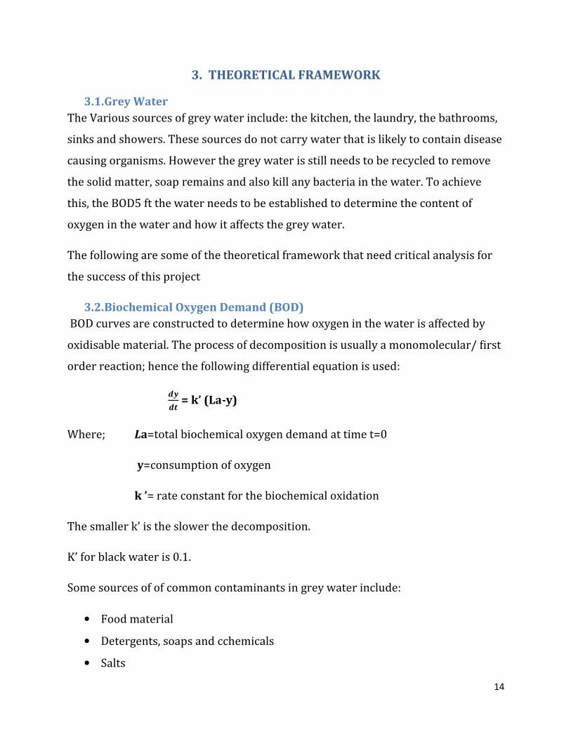
3.2. Biochemical Oxygen Demand (BOD)
BOD curves are constructed to determine how oxygen in the water is affected by
oxidisable material. The process of decomposition is usually a monomolecular/ first
order reaction; hence the following differential equation is used:
���� = k’ (La-y)
Where; La=total biochemical oxygen demand at time t=0
y=consumption of oxygen
k ’= rate constant for the biochemical oxidation
The smaller k’ is the slower the decomposition.
K’ for black water is 0.1.
Some sources of of common contaminants in grey water include:
• Food material
• Detergents, soaps and cchemicals
• Salts

15
3.3. Site Selection
In the process of assessing the suitability of sites for constructing greywater
treatment system, important considerations are as below:
Approximate size of 15 - 20 m land in the school campus for reuse system has been
considered
Topography and natural slope: the topography of the sites and contours can be
established using standard surveying procedures. The slope of the site is an
important factor in controlling surface ponding, runoff and erosion. A minimum of
2% slope of area is recommended. l Soil type: Soil type and properties are the key
factors in the design and operation of greywater reuse systems. The main
characteristics necessary for the evaluation of the soil for the purpose of greywater
reuse are soil texture, soil structure, corrosiveness, submergence, infiltration rate
through topsoil and percolation rate in the sub-strata. Percolation rates can be
determined using percolation tests and compared with textural classification charts.
Infiltration rates can be determined using a cylinder infiltrometer (Christov et al.,
1995). As sandy lighter soils can absorb more greywater, and heavier soils with a
high clay content absorb less (Greenhouse People's Environmental Centre, 2002)
therefore soil having structural stability i.e., stable clay/silt, hard strata soil is
recommended for greywater reuse system construction. Black cotton soil and sandy
soil should be strictly avoided
3.4. Head loss
It occurs due to passage of water through the filter media. The head loss equation is
derived from the fundamental equations of head loss. This can be calculated either
by using the Hazen Williams equation or the Darcy-Weisbach equation. Their
equations are as follows:

� Hazen Williams
� Darcy-Weisbach equation
3.5. The Pump characteristics
The three principle performance parameters relating to pump selection are as
follows:
o Flow / capacity
o Total Head
o Suction Lift;
a) CAPACITY: The required capacity was determined by relating
capacity to the total daily demand. Daily demand was estimated and the
hourly requirement computed by dividing the daily demand by the number of
hours the pump is required to work.
Hazen Williams equation
Weisbach equation:
The Pump characteristics
The three principle performance parameters relating to pump selection are as
CAPACITY: The required capacity was determined by relating the storage
capacity to the total daily demand. Daily demand was estimated and the
hourly requirement computed by dividing the daily demand by the number of
hours the pump is required to work.
16
The three principle performance parameters relating to pump selection are as
the storage
capacity to the total daily demand. Daily demand was estimated and the
hourly requirement computed by dividing the daily demand by the number of
17
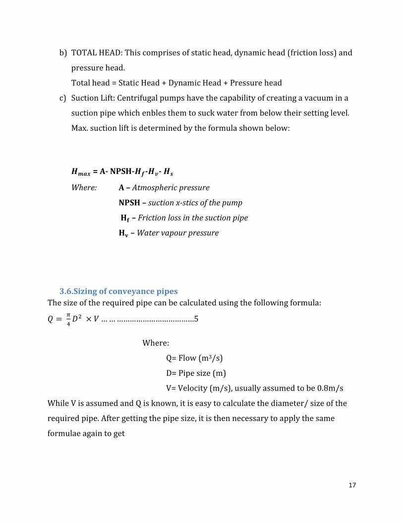
b) TOTAL HEAD: This comprises of static head, dynamic head (friction loss) and
pressure head.
Total head = Static Head + Dynamic Head + Pressure head
c) Suction Lift: Centrifugal pumps have the capability of creating a vacuum in a
suction pipe which enbles them to suck water from below their setting level.
Max. suction lift is determined by the formula shown below:
�� = A- NPSH-��-��- �
Where: A – Atmospheric pressure
NPSH – suction x-stics of the pump
�� – Friction loss in the suction pipe
�� – Water vapour pressure
3.6. Sizing of conveyance pipes
The size of the required pipe can be calculated using the following formula:
� = �� �� × � ……………………………………5
Where:
Q= Flow (m3/s)
D= Pipe size (m)
V= Velocity (m/s), usually assumed to be 0.8m/s
While V is assumed and Q is known, it is easy to calculate the diameter/ size of the
required pipe. After getting the pipe size, it is then necessary to apply the same
formulae again to get

18
3.7. Design of storage tank
In the design of the storage tank different elements are considered.
� The shear forces and moments caused by the horizontal earth pressure, on the
wall
� The net moment due to the earth pressure on the top and bottom faces of the
inner footings in the top.
� The moment due to earth pressure causes the tension in the bottom face of the
outer footing
The following cases will be considered for reinforcement:
1. When only water pressure acts
2. When the tank is empty.
Maximum and minimum pressure at the base will be given by:
�� = �� �� +
!� "………………………………..4
��#$ = �� �� −
!� "………………………………….5
Where: Q=pressure either maximum or minimum
W= total weight
B= breadth
e=eccentricity
Total horizontal pressure exerted by water will be given by:
& = '()
�
Where: p=total horizontal pressure

19
W=total weight
H=effective height
Maximum available friction=*+
Where: * =frictional coefficient
W= total weight
Factor of safety== *+ �,-.⁄
Where: �,-.=maximum pressure at the base
Bending moments:
1. Short span: 01. = 21. × + × 3�.
Where: Msx=moment in the shorter span
245 = the coefficient in the shorter span
W is the ultimate design load
2. long span:016 = 216 × + × 3�.
Where: Msy=moment in the long span
216= coefficient in the long span
W=ultimate design load
Lx=length of shorter span
Areas of reinforcement, As

20
74=8
9.;<=>×?
Where: As= area of reinforcement
M=moment
Fy=the respective stress (steel)
3.8. Tank Loadings
Are of 2 types;
• Internal loading caused by Hydrostatic and active pressures
• External loading-Hydrostatic pressures, Active soil pressures and reaction of
the ground
In order to meet the regulations as provided in the British Standard Codes of
practices, BS 5337,
• Minimum thickness of the wall, t = 100 mm
• T = 2.5% depth of the tank +25 mm
• Check limits for crack width for the water retaining structure, Cr = 0.15
The allowable stress in the steel reinforcement was reduced such that
Force N = A21@A × f21A
Where B21A = 100N/mm2

21
4. GENERATION OF CONCEPT DESIGN
I. Determining the quantity and quality of the grey water produced
weekly. This is achieved through determination of the average water
consumed per week by inquiry, observation and estimation
II. Determining a suitable stable site for putting up the system
components. Achieved through carrying out geotechnical tests such as soil
sampling and testing
III. Designing of the various system components of the recycling unit. The
following systems for the grey water recycling unit will be designed:
� Diversion System
� Filtration and treatment system
� Delivery and Storage system
� The design layout from CAD drawings
IV. A working grey water recycling system will be modelled to show the
directions of the different flows of fresh water and grey water.

22
5. METHODOLOGY
5.1. Study Area
5.1.1. Location
Mugabe Hostel is located in The University of Nairobi Upper Kabete Campus at
longitude 1°15’16.37” S and latitude 36°43’39.21” E and at an elevation of 6165 ft.
The proposed site for the grey water recycling unit will be at an elevation of 6170 ft
to allow for flow of water by gravity during treatment.
Figure 2: Google maps location of Mugabe Hostel.
23
5.1.2. Land Cover
The hostel is surrounded by plant cover majorly grass, trees and live fence. There
are various footpaths crisscrossing around the hostel and roads nearby.
5.1.3. Topography
The area is a relatively steady slope from south west to north east. The area is hilly
with various flat stretches of land.
5.1.4. Water Supply System
The current water supply system to the hostel is from the Nairobi Water and
Sewerage Company and supplemented by various boreholes sunk within the
campus. The inconsistency of the supply of Water from the mains has been an
inconvenience in pumping the water to the overhead tanks prompting numerous
ground water tanks to be erected to store the water
5.1.5. Waste Management
Since the sewerage system in the hostel is not connected to the Nairobi Sewerage
system, the waste water produced is directed towards a septic tank that ha s a
capacity of about 40,000 litres. Other than occasional leakages, the system has been
able to hold up to the waste produced from the hostel.
5.2. Data Collection
5.2.1. Water Consumption Data
The water consumption data was collected using the observation/data sheet as seen
in the appendix. The average amount of water consumed in the hostel was compute
from approximation, inquiry and estimation of the daily average volume of water in
the roof tank.
Other sources of information regarding data was sourced from the internet and
books

24
5.3. Design
5.3.1. Design of the diversion system
For maximum efficiency, the different components of the diversion system will be
assessed and the suitable material for each part will be determined
5.3.2. Filtration and Treatment System
The most appropriate treatment method which will produce more pure water is
selected and incorporated within this system. A simple charcoal-sand filter is
designed with the sizes of the filters and arrangement of the sand and charcoal
being crucial to the efficiency of the filter.
The location and slope of this system is crucial in facilitating the removal of waste at
a relatively low cost.
5.3.3. Delivery and Storage System
The delivery system will majorly comprise of a pump which will assist in increasing
the head to the overhead tank to allow for water to flow by gravity and different
pipe sizes for distributing the recycled water to various locations.
A suitable tank will also be determined with the capacity and material being crucial
to its longevity. The size of the tank will be determined from the average volume of
grey water collected daily.
5.3.4. Overall Design Layout
A schematic layout of the complete design which will incorporate each of th above
components will be illustrated via CAD drawings

25
6. RESULTS AND ANALYSIS
6.1. Water Consumption Data
The table below shows data obtained from Mugabe hostel in a span of 7 days in
order to get the average volume of water consumed in a day
Table 1: Average volume of water consumed in a day
Area/Day 1(l/d) 2(l/d) 3(l/d) 4(l/d) 5(l/d) 6(l/d) 7(l/d) Average %age
Bathroom
and Sinks 3500 3500 3500 3500 3500 4000 4000 3600 60%
Toilet 1500 1500 1500 1500 1500 2000 2000 1800 30%
Leakages 100 100 100 100 100 100 100 100 1.67 %
Other
uses 500 500 500 500 500 500 500 500 8.33%
TOTAL 5800 5800 5800 5800 5800 6600 6600 6000 100%
The amount of water consumed is calculated per day using the equation below:
CDEDFGHI�(3/LDI) = �3GHNOP/+OOQ�LDIP/+OOQ
Average volume demanded per person = 80 l/day
Average volume demanded by hostel = 80 l/day × 100pple = 8000 l/day
Average Volume supplied per day (litres) =6000
Average Volume per day (��) = 5.55�R

26
Approximate number of people in the hostel per day = 100 pple
Average volume per person per day = S�!TU!VWXY�!Z!T��(X#�T! )
[W�X$Y�\!TW�Z!WZX!#$�]!]W �!X
=^^^_�__
= 55.5 l/day
NB: 55.5 l/day is the volume of water available per person per day due to the water
supply
80.0 l/day is the volume of water demanded per person per day in the hostel
This grey water system is supposed to provide the deficit i.e. 25.5 l/day
Total amount of water supplied = tank capacity * no. of times the
water is pumped to the per day overhead tank
= 3000 l * 2
= 6000 l/day
Volume of grey water produced per day
No. of students = 100
Approximate number of times flushing the toilets = 150
Capacity of the cistern = 15 litres
Amount of black water produced per day = 15 × 150
= 2250 l/day

27
Approximate volume of grey water produced = 5500 – 2250
= 3250 l/day
Percentage of grey water produced = R`^_ ___ × 100%
= 54.2 %
6.2. Diversion System
6.2.1. Piping
The existing piping system conveyed waste water from both the toilets and
bathrooms towards the septic tank. The piping conveying the greywater should be
diverted away from the pipe system carrying the black water.
6.2.2. Junction Chamber
Grey water which originally headed towards the septic tank is diverted to a junction
chamber which facilitates draining out greywater from different sources. The
dimension of junction chamber is determined based on providing sufficient storage
to handle peak hourly volume. The standard dimension of the junction chamber is
kept at about 0.3 m x 0.3 m x 0.5 m i.e. a capacity of for a hostel having greywater
generation of 2000-3000 l/day. Froth removal generated from bathroom and
washing may prove necessary.
6.3. Filtration and Treatment System
6.3.1. Screen
Screen can be a mesh with less than 10 mm size to remove coarse particles. The
screens can be placed at the inlet to the piping system of sources such as bathroom,
sinks etc. to remove large particles and prevent an overload of particles at the outlet.
The screens can be cleaned manually and solids disposed off along with solid waste.

28
6.3.2. Equalization or Settling Tank
Equalization or settling tank is required to collect grey water for continuous flow to
the filters for treatment and facilitates in settling of course particles. It also allows
for balance flow by taking into account maximum flow of greywater generated
during morning hours due to bathroom use. Adequate aeration and mixing must be
provided to prevent odors and solids deposition in equalization tank and this is
achieved b by providing baffles.
Removal efficiency of suspended solids in sedimentation tanks depends on surface
area and depth of tank. Surface loading rate is the basic guidance parameter for
determining size of tank. The design criteria for equalization or settling tank
presented in table below.
6.3.2.1. Design Criteria for an Equalization Chamber
Loading = ��a9b/c-6��de1×fc-6
= 135.5 l/day
Table 2: Design Criteria for an Equalization Chamber
PARAMETER RANGE
Detention time (hrs) 1-2
Surface Loading (l/h/��) 100 – 200
Depth of Tank (m) 0.8 – 1.0
Length to Width ratio 3:1 to 4:1

29
Figure 3: Equalization chamber

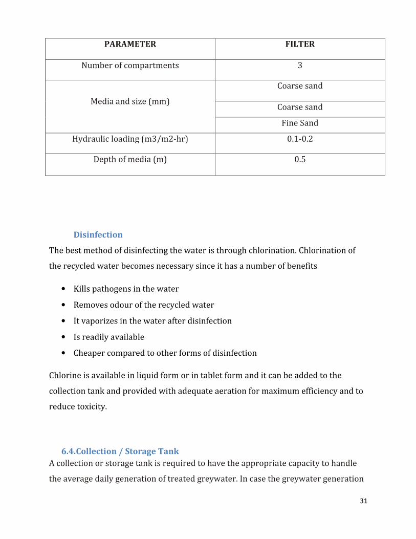
6.3.3. Filtration Unit
The most suitable filtration unit should consist of coarse sand
sand. This will
Figure 4: Filtration unit
Filtration Unit
The most suitable filtration unit should consist of coarse sand-charcoal and fine
30
charcoal and fine
31
Disinfection
The best method of disinfecting the water is through chlorination. Chlorination of
the recycled water becomes necessary since it has a number of benefits
• Kills pathogens in the water
• Removes odour of the recycled water
• It vaporizes in the water after disinfection
• Is readily available
• Cheaper compared to other forms of disinfection
Chlorine is available in liquid form or in tablet form and it can be added to the
collection tank and provided with adequate aeration for maximum efficiency and to
reduce toxicity.
6.4. Collection / Storage Tank
A collection or storage tank is required to have the appropriate capacity to handle
the average daily generation of treated greywater. In case the greywater generation
PARAMETER FILTER
Number of compartments 3
Media and size (mm)
Coarse sand
Coarse sand
Fine Sand
Hydraulic loading (m3/m2-hr) 0.1-0.2
Depth of media (m) 0.5
32
is large with a capacity of more than 4000 liter/day, collection tank may have
capacity to handle half of the quantity of greywater generated per day.
6.4.1. Material
The storage tank is constructed from concrete material because of the following
properties
� It durable and lasts longer than other materials
� It is a reliable material
� It has a high compressive strength
� It is cheaper than most materials
� It is isotropic and hence suitable for water retaining structures
� Is non-corrosive with chlorine
6.4.2. Shape and Position
A rectangular tank is suitable for use as a storage tank. The best position for this
tank should be underground and at a distance from the septic tank. It should also be
higher than the septic tank as a measure of control. The various pipes conveying the
water along the system should be buried a distance of 1m below the ground to avoid
damage or hinder movements of other users.
The major parts of the tank that will need to be designed include:
� Base of the tank or bottom slab
� Tank walls
� Top slab or cover of the tank

33
6.4.3. Dimensions of the storage tank
Length: width ratio = 4:1
Depth of tank =1 m
Volume of grey water produced = 3.25 ��/day
Volume = l × w × d
Volume =4+�d
3.25 = 4 × +� × 1
0.8125 = +�
W = √0.8125)
= 0.9 m ≈ 1m
L = 4 × 0.9
=3.61 m ≈ 3.6 m
Therefore the storage tank dimensions are 3.6 × 1 × 1

34
Figure 5: Storage Tank

35
6.5. Pumping and Piping System
6.5.1. Pipes
The Various pipes that link the different components are installed in the system and
should comprise of the following:
6.5.2. Pumps
An electric pump is a preferred choice since the hostel has ample electric power.
Efficient centrifugal pumps are ideal where water requirements are substantial and
only single-phase power, and sufficient power available.
These are normally low cost balanced and with rigged construction. It has no
centrifugal switch, require less operational and maintenance cost with no air lock
problems. The pump should have a minimal yield (Q) of 1000 liter/hour and should
be a high head/low discharge pump
Table 5: Pump characteristics
Property Values
Lift 22 m
Flow rate 5.0m�/h
Voltage 240 v ac

36
Figure 6: Pump

37
6.6. COST BENEFIT ANALYSIS
The grey water recycling system will also save the overall cost of piped water by
reducing the intake. Calculating the total cost of water saved at current rates is:
Cost of water: 1 litre = Kshs 0.002
Approximate of 3000 litres of water recycled per day
= 3000 l/day × Kshs 0. 02
= 60 Kshs / day
In a Month = 60 × 30
= Kshs 1,800 per month
In a year = 1800 × 12
= Kshs 21,600 per year

6.7. SCHEMATIC DIAGRAM OF A GREY WATER RECYCLING SYSTEM
SCHEMATIC DIAGRAM OF A GREY WATER RECYCLING SYSTEM
38
SCHEMATIC DIAGRAM OF A GREY WATER RECYCLING SYSTEM

39
6.8. Water Quality Monitoring
Various precautionary measures should be taken to ensure that the fresh and grey
water do not mix. These include
1. No cross connection of the grey water piping system with the fresh water
piping system
2. Use of different colour pipe network
3. Prevention of mosquito breeding in the system
6.8.1. Odour Control
Good design and maintenance practices will reduce odour problems in greywater
treatment system without the use of chemical addition or air treatment. The
charcoal and chlorine also assists in removing the odor from the water. the
following measures are recommended to minimize odour problem:
I. A minimum slope of 2-3 % should be provided so as to ensure sufficient flow
through system when in operation
II. Baffles should be provided at the entrance of sedimentation tank and in
collection tank for aeration.
III. The closed conduit system should be avoided. If a closed conduit system is
unavoidable, length should be minimal with adequate velocity to scour the
pipe.
IV. Deposited solids should periodically be removed from equalization tank
V. Natural/ artificial coagulants should be added to sedimentation tank to aid in
the coagulation process.
VI. Addition of chemicals such as calcium nitrate, hydrogen peroxide, potassium
permanganate, hypochlorite and chlorine added to the system to oxidize the
sulphate bearing ingredients of greywater. This is only necessary if the
system cannot be designed in such a way to prevent formation of anaerobic
conditions

40
VII. Filters should be washed with clean water and filter media should be
periodically replaced.
VIII. Chlorination of final effluent also helps in minimizing odour
IX. Collection sump can be covered and vent pipe can be provided to let out the
odourous compound
6.9. Maintenance of Greywater Treatment System
The success of a greywater reuse system will depend on maintaining the system.
Any defect must be rectified as soon as it becomes apparent. Greywater systems
require regular maintenance e.g. weekly cleaning or replacing filters, periodic
desludging, and manually diverting greywater back to sewer and flushing of
drainage lines.
The following procedures may be required to be undertaken once the system starts-
up:
• Weekly maintenance of systems with filtering devices e.g. screens
• Sedimentation tanks require desludging every month
• Warning signs should be maintained in good order
• Protection from any contact with greywater to ensure that exposed body
areas that come into contact with greywater are immediately washed; not
make contact with the mouth or face either directly
• Use of greywater only for toilet flushing and to completely avoid use for anal
cleaning or hand washing

41
Summary of the system maintenance
Treatment Unit Activity Frequency Purpose
Equalization Tank De-sludging Every fort night Maintain the volume
of equalization tank
Filtration Unit Cleaning of filter
media
Every fort night
Maintain the
efficiency
Refill the upper
layer
Every fort night Overcome chocking
problem
Chlorination Maintain proper
dose
Daily Disinfection and
Odor control
Collection tank Reuse of water Every 2 days Maintain the quality
of greywater

42
7. CONCLUSION
The grey water produced within the hostel comprised of about 55% of the total
amount of water used and therefore the water recycling saves up to an equivalent
percentage off the mains supply which is a capacity of about 3000 litres per day or
3m�.
The recycled water is of good quality and can therefore be used primarily for
flushing toilets and cleaning of the pavements. Other uses will be watering the
flower bed surrounding the hostel and improve beautification.
This system will also be able to save on the cost of water supplied by the Nairobi
water and sewerage company. An estimate of about Kshs 21,600 will be saved on a
yearly basis.
Given that this system will have an economic life similar to that of the hostel, it
translates that with proper maintenance, the system will be able to serve the
students and improve the sanitation of the hostel.

43
8. RECOMMENDATION
This project should be implemented to improve the sanitation levels of the hostel
and reduce the long term costs in water supply.
The project can also be modified to handle the various volumes of grey water
produced by other hostels in the campus and ultimately be implemented in each and
every hostel.
In case of a system with anaerobic, iodine tablets can be used for disinfection
instead of chlorine.

44
9. REFERENCES
Jeppersen B. and Solley D. 1994: Domestic Grey water reuse: Overseas practice
and its applicability to Australia. Research Report No 73. Urban Research
Association of Australia, Brisbane city Council
Little, V. 2000: Residential grey water reuse: The Good, The Bad, The healthy.
Tucson, AZ: The Water Conservation Alliance of southern Arizona (Water CASA),
2009
Mullegger E, Langergrabber G. Jung H. Starkl M. and Laber J. 2003: Potential for
Grey water treatment and reuse in rural areas, 2nd International Symposium on
ecological sanitation
Myca T. 2002. The Effect of Portable vs. Grey Water on radish Growth
Peter L.M. Veneman and Bonnie Stewart 2002: Grey water characterization And
Treatment Efficiency; Final Report for The Massachusetts Department of
Environmental Protection, Bureau of Resource Protection, December 2002
Poff, J A. 2006 The Use of Grey Water as a Water Conservation Method: Civil
Engineering, Horticulture &Landscaping, urban Water Infrastructure, and Soil
&Crop Sciences, Colorado State University. Fort Collins, CO: Colorado State
University. Preview of a study taking place at the Colorado State University
Esrey S. 1998. Ecological Sanitation Edited by Uno Windblad. Published by the
department of Natural resources and the Environment, Sida, S-105 25 Stockholm,
Sweden
Roesner, L.2006. Long-term effects of Landscape Irrigation Using Household Grey
water -Literature Review and Synthesis. Water Environmental Research

45
Foundation. Fort Collins, Colorado: Water Environmental Research Foundation and
the Soap and Detergent Association
Schneider L. 2009. Grey Water reuse: Rule Development Committee Issue Research
Report Final, July 2009
Turner S. 2001. “Will there be Enough Water in The Next Century?” Microsoft
Encarta Encyclopedia
Seigrist, Robert L. 1978. Management of Residential Grey Water: Small Scale Waste
Management Project, University of Wisconsin. Madison, Wisconsin: University of
Wisconsin, 1978. Technical Memorandum
Wright M. 1986: Safe Use of Household grey water, Guide -106- New Mexico State
University
A-Boal, D. Christov, Lechte, P. and Shipton, R. 1995. Installation and Evaluation of
Domestic grey water reuse Systems: Executive Summary. Department of Civil and
Building Engineering, Victoria University of Technology, Victoria, Australia: Victoria
University of technology, 1995. Technical Memorandum
Al- Jayyousi, Odeh.2002. Focused Environmental Assessment of Grey water Reuse
in Jordan. Civil Engineering Department Applied Science University, College of
Engineering. Amman, Jordan: Environmental Engineering Policy (2002) 3,
2002.pp.67-73, study
Brown, C.2009. Recycled Water: Risks, benefits, economics and regulation by
system scale. New Zealand Land Treatment Collective conference proceedings
(Technical Session 30): Recycling of Water. Taupo 25-27 March 2009
46
10. APPENDICES
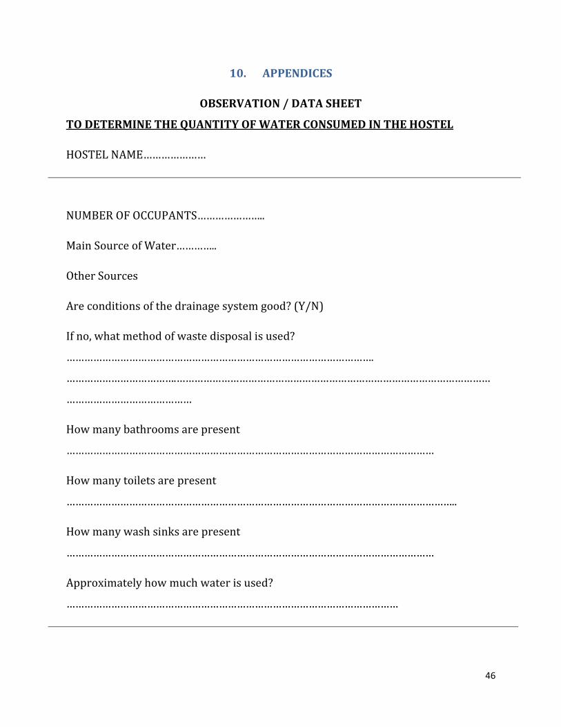
OBSERVATION / DATA SHEET
TO DETERMINE THE QUANTITY OF WATER CONSUMED IN THE HOSTEL
HOSTEL NAME…………………
NUMBER OF OCCUPANTS…………………..
Main Source of Water…………..
Other Sources
Are conditions of the drainage system good? (Y/N)
If no, what method of waste disposal is used?
………………………………………………………………………………………….
……………………………….……………………………………………………………………………………………
……………………………………
How many bathrooms are present
……………………………………………………………………………………………………………
How many toilets are present
…………………………………………………………………………………………………………………..
How many wash sinks are present
……………………………………………………………………………………………………………
Approximately how much water is used?
…………………………………………………………………………………………………

47
What is the capacity of the storage tank?
………………………………………………………………………………………..........
How long does it take to empty?
……………………………………………………………………………………………………………..
Are there any leakages?
……………………………………………………………………………………………………………………………
Approximate how many times the toilets are flushed per day
………………………………………………………………....
Any other uses of water in the
hostel………………………………………………………………………………………………………..
Approximate how much water is used for these
uses………………………………………………………………………………..

48
TANK MATERIAL PROPERTIES
TANK MATERIAL ADVANTAGES DISADVANTAGES
plastic
fiberglass commercially available,
alterable and moveable,
little maintenance light weight
Must be sited on smooth solid,
level footing pressure proof for
below ground installation
polyethylene Commercially available alterable,
moveable, affordable, available in
variety of sizes ,install above or
below ground
UV –degradable, must be
painted or tinted, pressure proof
for below ground installation
Trash cans (20-50 gallons) Commercially available,
inexpensive
Must use new cans, small
storage capacities
Metal
Galvanized steel tanks Commercially available, alterable
and movable, available in variety of
sizes, film develop inside to prevent
corrosion
Possibly corrosion and rust, must
be lined for potable use, only
above ground use
Steel drums (55-gallons) Commercially available, alterable
and moveable
Verify prior to use for toxics,
prone to corrosion and rust ,
small storage capabilities
Concrete
Ferroconcrete Durable and immoveable, install
below or above ground
Potential to crack and leak,
neutralizes acid rain
Monolithic/poured-in-place Durable, immoveable, versatile,
install below or above the ground,
decreases rainwater corrosiveness
Potential to crack and leak,
permanent, neutralizes acid rain,
in clay soil, do not place
underground
Stone, concrete block Durable and immoveable, keeps
water cool in hot climates
Difficult to maintain, expensive
to build

3D VIEWS OF THE SYSTEM PARTS
3D VIEWS OF THE SYSTEM PARTS
49

50
DIFFERENT VIEWS OF THE RECYCLING UNIT

51
EQUILIZATION CHAMBER

52
FILTRATION UNIT

53
STORAGE TANK

54
PUMPING SYSTEM