design of a small detachable backhoe · design of a small detachable backhoe ... machines are...
TRANSCRIPT
Design of a Small Detachable Backhoe
Prepared by:
Yen Kean Lee
David W. Crossley
Jacob A. Hamburger
Biosystems & Agricultural Engineering Department
Oklahoma State University
Submitted to:
AGCO National Student Design Competition
May 22, 2005
ii
Design of a Small Detachable Backhoe David W. Crossley
Jacob A. Hamburger Yen Kean Lee
Biosystems & Agricultural Engineering Department Oklahoma State University
Submission Date: May 22, 2005
David W. Crossley Biomechanical Option May 2005 Graduate Okarche, Oklahoma
Jacob A. Hamburger Biomechanical Option May 2005 Graduate
Weatherford, Oklahoma
Dr. Paul R. Weckler Senior Design Advisor
Dr. Ronald L. Elliott BAE Department Head
iii
Abstract
Charles Machine Works, Inc. (CMW) produces a wide range of underground and
earthmoving equipment. Over the past five years, the company has developed a new
line of products known as compact utility machines. The compact utility industry is
currently occupied by several manufacturers, including CMW. Compact utility
machines are typically compact loader type units that mate to a multitude of
attachments allowing them to accomplish many different tasks. Since their inception,
CMW has been working to create a product line of attachments for the machines made
at the CMW plant in Perry, Oklahoma. Engineering Specialties was approached and
asked to design a small backhoe for a CMW manufactured compact utility machine. In
addition to upholding the same traditions of quality and value as other CMW machines,
the backhoe also had to meet a strict list of design criteria to comply with both CMW
and industry standards. Through field research and design, Engineering Specialties was
able to produce a successful working prototype which is continuing to be used even
today. Through our design, testing, and construction, our team has successfully met or
surpassed the design criteria set forth by our sponsors.
Acknowledgements
Eddy Allen – Ditch Witch Design Engineer and project mentor Joe Worlow – Ditch Witch Design Team Manager and project mentor Wayne Kiner - Oklahoma State University Biosystems and Agricultural Engineering
Laboratory Manager Dr. Paul Weckler - Oklahoma State University Biosystems Engineering Senior Design
Advisor
Special thanks to all the design and test personnel at Ditch Witch who answered our questions and provided guidance and assistance throughout the project.
iv
Table of Contents Abstract.............................................................................................................................. iii
Acknowledgements............................................................................................................ iii
Introduction......................................................................................................................... 1
Problem Statement.............................................................................................................. 2
Statement of Work .............................................................................................................. 3
Patent & Market Research .................................................................................................. 5
Patent Research............................................................................................................... 5
Market Research ............................................................................................................. 5
Engineering Specifications ................................................................................................. 7
Design Concepts ................................................................................................................. 8
Design Concept 1.......................................................................................................... 10
Design Concept 2.......................................................................................................... 11
Design Concept 3.......................................................................................................... 12
Final Design Selection ...................................................................................................... 14
Final Design Implementation............................................................................................ 15
Frame ............................................................................................................................ 15
Boom and Dipper.......................................................................................................... 20
Testing Results.................................................................................................................. 23
Further Recommendations................................................................................................ 24
Project Schedule ............................................................................................................... 27
Project Budget – Cost Analysis ........................................................................................ 27
Conclusion ........................................................................................................................ 29

v
Appendix A – Gantt Chart ................................................................................................ 32
Appendix B – In system parts list ..................................................................................... 33
Appendix C – Component Drawings................................................................................ 35
vi
List of Illustrations
Figure 1: Ed Malzahn and his revolutionary trencher. ...................................................... 1
Figure 2: Backfill blade built in to main frame of backhoe............................................... 4
Figure 3: Toro Dingo compact utility unit......................................................................... 6
Figure 4: Bobcat compact utility loader with pallet fork attachment. ............................... 7
Figure 5: Ditch Witch SK500 with BradCo backhoe attachment...................................... 8
Figure 6: Track skid marks left after digging with prototype machine. ............................ 9
Figure 7: Top view of compound arm design.................................................................. 10
Figure 8: Double-ended cylinder and chain rotation system. .......................................... 11
Figure 9: First prototype tested at Ditch Witch. .............................................................. 13
Figure 10: Ditch Witch Concept 1 small detachable backhoe......................................... 14
Figure 11: CAD drawings of backhoe. ............................................................................ 15
Figure 12: Flat pattern layout of main frame with holes at top for valve attachment...... 17
Figure 13: Top link for quick attach system. ................................................................... 17
Figure 14: Stabilizer in folded up position inside the edge of the blade.......................... 19
Figure 15: Stabilizer arm in down position. .................................................................... 20
Figure 16: Backfill blade with cutting edge..................................................................... 21
Figure 17: Floorboard with front and side foot guard...................................................... 22
Figure 18: Final backhoe design attached to SK500....................................................... 23
Figure 19: Cylinder stop preventing full retraction. ........................................................ 26
Figure 20: Final cost table including assembly costs....................................................... 28
Figure 21: Ditch Witch vs. BradCo backhoe feature comparison. .................................. 29

1
Introduction
Charles Machine Works, Inc. (CMW) is a manufacturing company that builds
construction equipment in Perry, Oklahoma. Over the past 50 years, CMW has become
synonymous with building the highest quality underground construction equipment in
the world. They began in the late 1940s with a mechanical powered trencher that
owner and founder Ed Malzahn built in his father’s machine shop (Figure 1).
Figure 1: Ed Malzahn and his revolutionary trencher.
This one machine has evolved into what the world now knows today as Ditch Witch®.
For the past 50 years, Ditch Witch has expanded its lineup to include horizontal boring
machines, vibratory plows, and more recently, compact utility machines.
Ditch Witch is an industry leader in the trenching market, introducing the first
mechanical trencher in 1949, and has continued to be on the forefront with the latest
innovative technology ever since. Over the years, their product line has expanded to
include various size trenchers as well as vibratory plows and backhoes. In the late
1980s, they began to explore the emerging horizontal boring industry and eventually
2
produced an entire line of directional boring machines. More recently, Ditch Witch has
decided to expand its lineup and branch out into the compact utility market.
The compact utility market segment has exploded in the last few years and is
currently the fastest growing segment of the construction equipment industry. Ditch
Witch manufactures multiple models that fall into this category. The vehicles have the
capability of attaching over 70 different tools to the front, making these some of the
most versatile machines on earth. Currently, this market produces annual net sales of
approximately six billion dollars worldwide, making it an excellent venture for any
company already involved in the construction industry. Unfortunately, several other
companies, both large and small have begun to manufacture similar machines and
attachments.
Problem Statement
Our team has accepted the challenge to design a small, detachable backhoe for the
SK500 compact utility machine. Currently, Ditch Witch offers a backhoe for this
model, but it is outsourced from another company. The purchased backhoe does not
satisfy many of the design criteria desired by Ditch Witch. Therefore, Ditch Witch has
decided it would be beneficial to their company if they were to design and build a
backhoe of their own. This would allow them to offer some additional features as well
as help to increase the overall profit margin on the SK500. The backhoe designed by
our team will fit the SK500 compact utility machine and adhere to all of the design
criteria set forth by Ditch Witch.
3
Statement of Work
For our design project, the team will be designing a small, detachable backhoe for
a compact utility unit manufactured by Charles Machine Works, Inc. in Perry,
Oklahoma. Charles Machine Works, also known as Ditch Witch, is one of the leading
manufacturers of trenching and underground excavating equipment in the world. Over
the past 50 years, the compact utility market segment has grown into a six billion dollar
worldwide market. Ditch Witch has released two hugely popular compact utility
vehicles: the SK300 and the SK500. These small vehicles can utilize over 70 different
attachments, making them possibly two of the most versatile tools to enter the market
in the last 30 years. Currently, many of the attachments for the SK’s are purchased
from outside vendors. However, Ditch Witch is now interested in producing more of
these attachments “in house.” This offers multiple benefits including the knowledge
that the equipment they sell is completely compatible with their machines and an
increased profit margin. One such attachment is the mini backhoe.
After meeting with the design engineers from Ditch Witch, the team set forth
some of the criteria this unit was expected to meet. First of all, it would have to attach
to the SK500 unit via the quick-attach plate in the front of the machine. Our team
would also have to assure the overall width of the backhoe did not exceed 36 inches,
making even the smallest spaces accessible. In addition, the backhoe would also have
to dig to a depth of at least 78 inches and have an overall weight not exceeding that of
the current purchased unit (780 lbs.). The backhoe must incorporate some sort of
mechanism to “lockout” the use of the tilt function on the attachment plate. Users will
often rotate the attachment plate to reposition the backhoe to get a deeper or larger hole.
4
This may be unsafe for the user and make the machine unstable. The unit would be
powered by the attachment hydraulic circuit on the machine, include safety kill
switches, and have all wires and hoses easily disconnectable at the mount plate. While
accomplishing these things, it would also need to outperform the current model in some
areas.
Some of the features required to exceed those of the present model include
allowing the hood to open while the unit is attached as well as being easy and quick to
disconnect (less than 5 minutes). Ditch Witch also desires to have some type of
stabilizers to keep the SK balanced and steady during normal operation. The team
looked at multiple approaches to this problem and agreed that further testing would
help confirm solutions. Most conventional backhoes use a pair of pads that raise and
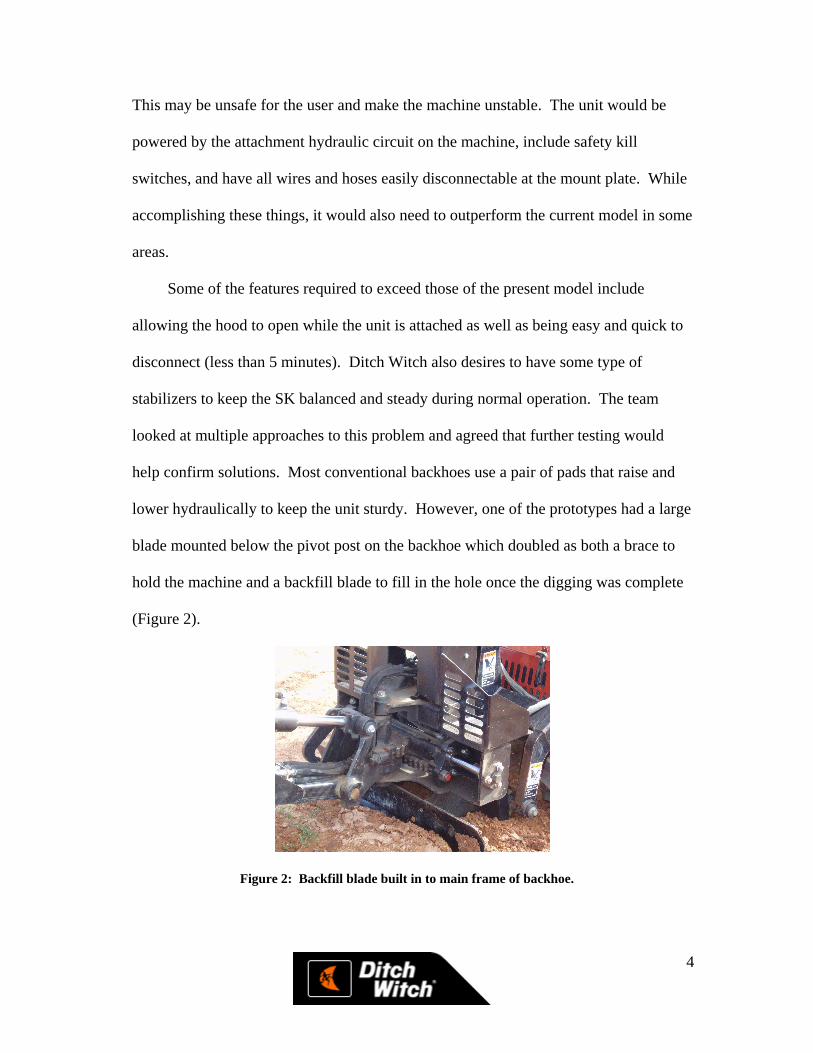
lower hydraulically to keep the unit sturdy. However, one of the prototypes had a large
blade mounted below the pivot post on the backhoe which doubled as both a brace to
hold the machine and a backfill blade to fill in the hole once the digging was complete
(Figure 2).
Figure 2: Backfill blade built in to main frame of backhoe.
5
In addition, the backhoe would also be composed of as many “in-system” Ditch
Witch parts as possible (cylinders, valves, bushings, etc…). This would not only make
it easier to manufacture but cheaper as there would be no need for additional tooling.
The design should also have a light kit included. Light kits have become much more
commonplace on backhoes as they are used in residential areas or near streets where
high visibility is imperative.
Patent & Market Research
Patent Research
To begin our research into backhoe design, the team did preliminary research into
backhoe and small digging attachment designs. Many of the backhoe patents found
were outdated. Most of the patents having to do with the backhoe design or design of
the hydraulic systems were issued back in the 1960s and 1970s, making them obsolete.
As the group began to search the internet, the absence of applicable patents became
even more evident as the team found several different manufacturers of both small and
detachable backhoes for use on small tractors, compact utilities, and other machines.
Market Research
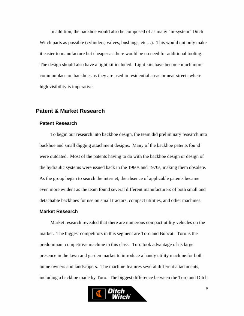
Market research revealed that there are numerous compact utility vehicles on the
market. The biggest competitors in this segment are Toro and Bobcat. Toro is the
predominant competitive machine in this class. Toro took advantage of its large
presence in the lawn and garden market to introduce a handy utility machine for both
home owners and landscapers. The machine features several different attachments,
including a backhoe made by Toro. The biggest difference between the Toro and Ditch
6
Witch machines is the use of rubber tires on the smaller Toros (Figure 3) versus tracks
on the SK.
Figure 3: Toro Dingo compact utility unit.
The backhoe currently offered by Toro is considered a light duty machine, with
less potential in the more rugged construction industry. However, it provides a light
and effective choice for customers needing to do small excavation jobs.
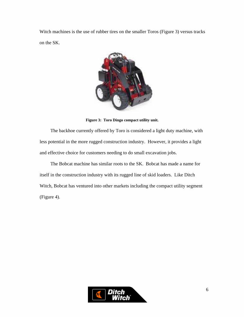
The Bobcat machine has similar roots to the SK. Bobcat has made a name for
itself in the construction industry with its rugged line of skid loaders. Like Ditch
Witch, Bobcat has ventured into other markets including the compact utility segment
(Figure 4).
7
Figure 4: Bobcat compact utility loader with pallet fork attachment.
While Bobcat does not currently offer a backhoe option with their compact utility
machine, consumers can still purchase aftermarket backhoes for the Bobcat machines.
Ditch Witch is looking to take advantage of its already established customer base
in the small to mid-range construction equipment much like Toro and Bobcat did in
their respective industries.
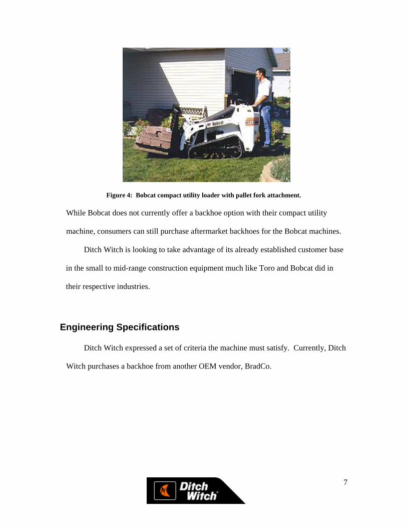
Engineering Specifications
Ditch Witch expressed a set of criteria the machine must satisfy. Currently, Ditch
Witch purchases a backhoe from another OEM vendor, BradCo.
8
Figure 5: Ditch Witch SK500 with BradCo backhoe attachment.
While robust and effective, the BradCo backhoe lacks many of the refinements
and features Ditch Witch desired. Below is a list of specifications for the backhoe
attachment set forth by Ditch Witch.
� Attach with the Ditch Witch quick couple on the SK 500.
� No wider than 36”.
� Incorporate some kind of stabilizing system.
� Use as many “in-system” components as possible.
� Lock on tilt.
� Must have a remote kill switch at operator’s seat. (Ditch Witch Standard)
� Dig a 6’ 6” deep hole.
� Ability to open the hood fully on the SK 500 while backhoe is attached.
Design Concepts
The team has formed some feasible design concepts based on limited testing. Due
to an extremely wet weather pattern, the team has only been able to test the designs
once. During that period, valuable insight was gained on how the prototypes work as
well as what features helped or hindered the digging process. Our team was unable to
9
do any further testing with the machines to become more familiar with them and aid in
our concept development.
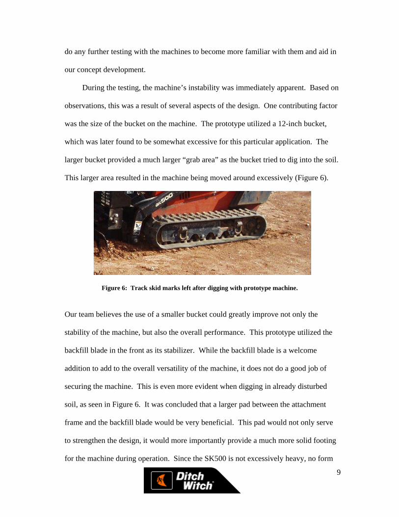
During the testing, the machine’s instability was immediately apparent. Based on
observations, this was a result of several aspects of the design. One contributing factor
was the size of the bucket on the machine. The prototype utilized a 12-inch bucket,
which was later found to be somewhat excessive for this particular application. The
larger bucket provided a much larger “grab area” as the bucket tried to dig into the soil.
This larger area resulted in the machine being moved around excessively (Figure 6).
Figure 6: Track skid marks left after digging with prototype machine.
Our team believes the use of a smaller bucket could greatly improve not only the
stability of the machine, but also the overall performance. This prototype utilized the
backfill blade in the front as its stabilizer. While the backfill blade is a welcome
addition to add to the overall versatility of the machine, it does not do a good job of
securing the machine. This is even more evident when digging in already disturbed
soil, as seen in Figure 6. It was concluded that a larger pad between the attachment
frame and the backfill blade would be very beneficial. This pad would not only serve
to strengthen the design, it would more importantly provide a much more solid footing
for the machine during operation. Since the SK500 is not excessively heavy, no form
10
of stabilizer can be expected to keep the machine completely anchored. However, our
group concludes that the pad and blade combination would provide an adequate anchor
without disturbing the soil.
Another area needing to be addressed in this design is the hydraulic control valve.
While the valve used on the prototype was adequate, our group feels the control
characteristics could be improved to help bolster the overall efficiency of operation.
The prototype had a reduction orifice in one of the ports. Unfortunately, the orifice was
in the wrong port, and it became immediately evident how much this affected the
handling characteristics of the machine.
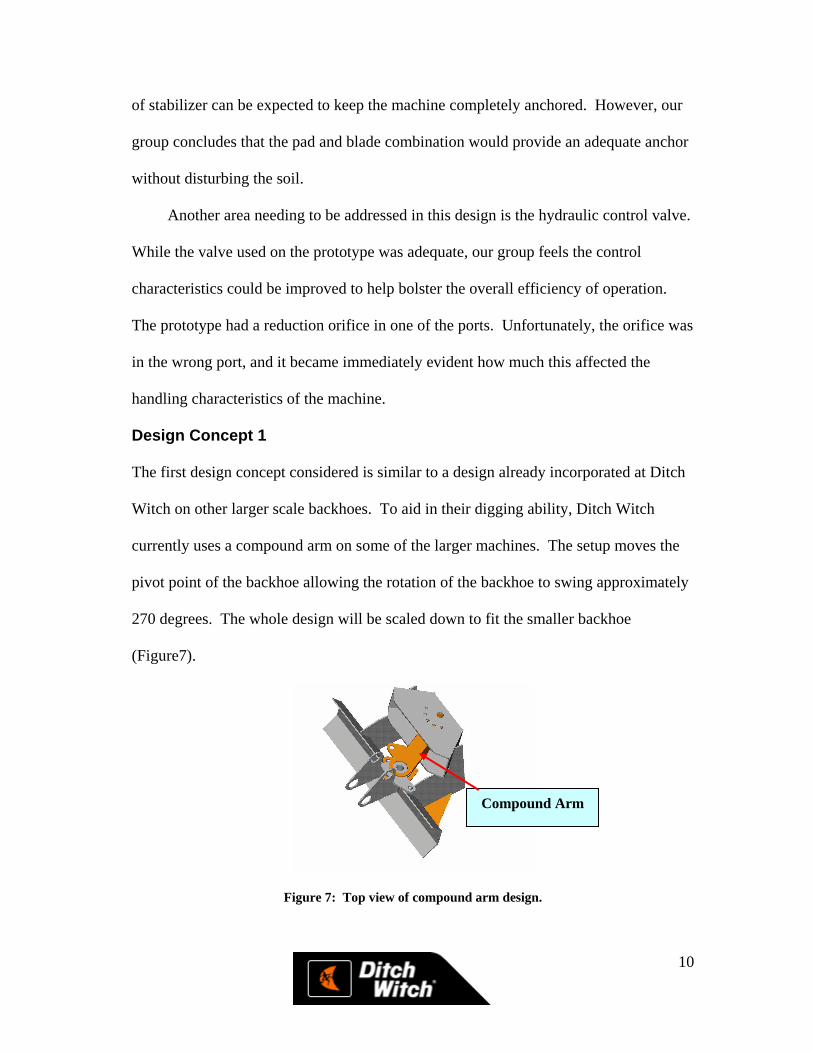
Design Concept 1
The first design concept considered is similar to a design already incorporated at Ditch
Witch on other larger scale backhoes. To aid in their digging ability, Ditch Witch
currently uses a compound arm on some of the larger machines. The setup moves the
pivot point of the backhoe allowing the rotation of the backhoe to swing approximately
270 degrees. The whole design will be scaled down to fit the smaller backhoe
(Figure7).
Figure 7: Top view of compound arm design.
Compound Arm
11
The biggest advantage offered by this setup is the ability to make the backhoe unit
offset. The user is able to move the pivot point of the backhoe across the front of the
machine. This feature is especially useful in residential or small areas that require the
machine to dig next to an obstacle such as a fence or structure. In addition, many of the
components needed to construct such a design are in-system parts.
With the compound arm design, the overall center of gravity of the machine
would be shifted in front of the main backhoe frame. Therefore, the machine would
tend to be heavier in the front. This will increase down force on the stabilizers, making
the machine more stable and much safer.
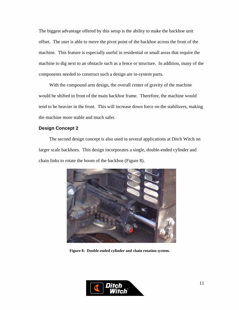
Design Concept 2
The second design concept is also used in several applications at Ditch Witch on
larger scale backhoes. This design incorporates a single, double-ended cylinder and
chain links to rotate the boom of the backhoe (Figure 8).
Figure 8: Double-ended cylinder and chain rotation system.

12
The design is compact and effective at rotating the boom in a confined space.
However, the double-ended cylinder is rather expensive and there have been some
concerns with chain tension in the past. Also, with this design the pivot is stationary
and cannot be offset as in design concept one. One challenge has been maintaining the
proper tension on the chains. On some of the larger backhoes, Ditch Witch has
encountered problems with slack in the chain at different points in the rotation because
the radius of the pivot is not constant. The pivot is a cast part keeping the dimensions
exact can be a challenge. On larger models, a small percent change in dimensions can
result in big changes in the radius causing slack in the chains. Users try to tighten the
chain to take out the slack and over-stretch the chain as it runs through the full turn arc.
This small backhoe requires a much smaller pivot, improving manufacturing tolerances.
As a result, this problem becomes insignificant.
The booms are redesigned to reduce the overall weight of the machine. The
geometry and location of pivot and hinge points will remain approximately the same,
keeping the digging depths and overall functionality of the machine as similar as
possible to the other prototypes.
The main frame is the same as the one used on the prototype machines. Not only
does this frame mate well to the pivot and backfill blade, it is also meets the 36-inch
width specification.
Design Concept 3
The third concept is a modified version of a concept already built by Ditch Witch.
This design is similar to design concept one (Figure 9).
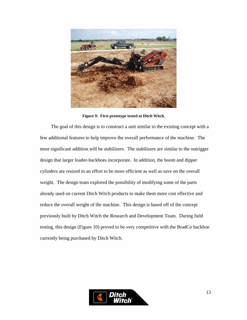
13
Figure 9: First prototype tested at Ditch Witch.
The goal of this design is to construct a unit similar to the existing concept with a
few additional features to help improve the overall performance of the machine. The
most significant addition will be stabilizers. The stabilizers are similar to the outrigger
design that larger loader-backhoes incorporate. In addition, the boom and dipper
cylinders are resized in an effort to be more efficient as well as save on the overall
weight. The design team explored the possibility of modifying some of the parts
already used on current Ditch Witch products to make them more cost effective and
reduce the overall weight of the machine. This design is based off of the concept
previously built by Ditch Witch the Research and Development Team. During field
testing, this design (Figure 10) proved to be very competitive with the BradCo backhoe
currently being purchased by Ditch Witch.
14
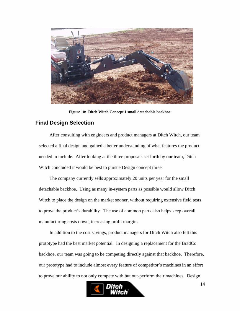
Figure 10: Ditch Witch Concept 1 small detachable backhoe. Final Design Selection
After consulting with engineers and product managers at Ditch Witch, our team
selected a final design and gained a better understanding of what features the product
needed to include. After looking at the three proposals set forth by our team, Ditch
Witch concluded it would be best to pursue Design concept three.
The company currently sells approximately 20 units per year for the small
detachable backhoe. Using as many in-system parts as possible would allow Ditch
Witch to place the design on the market sooner, without requiring extensive field tests
to prove the product’s durability. The use of common parts also helps keep overall
manufacturing costs down, increasing profit margins.
In addition to the cost savings, product managers for Ditch Witch also felt this
prototype had the best market potential. In designing a replacement for the BradCo
backhoe, our team was going to be competing directly against that backhoe. Therefore,
our prototype had to include almost every feature of competitor’s machines in an effort
to prove our ability to not only compete with but out-perform their machines. Design
15
Concept three offered the best combination of cost effectiveness, manufacturability,
and performance.
Final Design Implementation
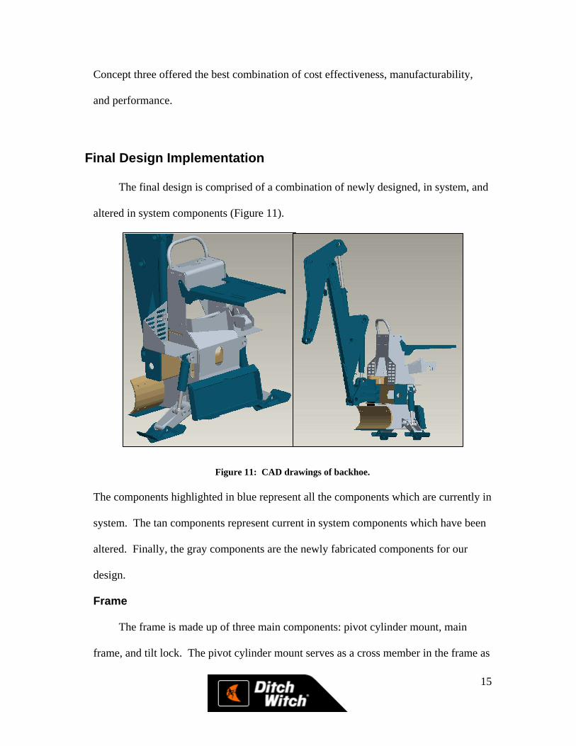
The final design is comprised of a combination of newly designed, in system, and
altered in system components (Figure 11).
Figure 11: CAD drawings of backhoe.
The components highlighted in blue represent all the components which are currently in
system. The tan components represent current in system components which have been
altered. Finally, the gray components are the newly fabricated components for our
design.
Frame
The frame is made up of three main components: pivot cylinder mount, main
frame, and tilt lock. The pivot cylinder mount serves as a cross member in the frame as

16
well as an attach point for the cast pivot. The cylinder mount weldment is composed of
eight parts currently used as an assembly on the HT25 model backhoe at Ditch Witch.
The weldment consists of two bosses welded to a flat plate and a bent C-channel plate.
Two gussets are used to support the top mount for the pivot while two more plates are
welded to each end of the C-channel to help secure the double-ended cylinder. The end
plates are made from 0.50 in. thick 1018 CR steel while the gussets, top plate, and C-
channel are made from 0.188 in. 1018 CR steel. All of these parts were made from
thicknesses similar to in system parts.
The second frame component is the main frame itself. The main frame is a single
piece of 0.188 in. thick 1018 CR steel with five bends to form the box of the frame
small gussets on the bottom to support the quick-attach plate. The frame is cut to
accommodate the pivot cylinder housing and backfill blade on the front as well as the
quick-attach plate on the rear. It features holes in the top of the frame which are used to
hold the hydraulic control valve in place (Figure 12).
17
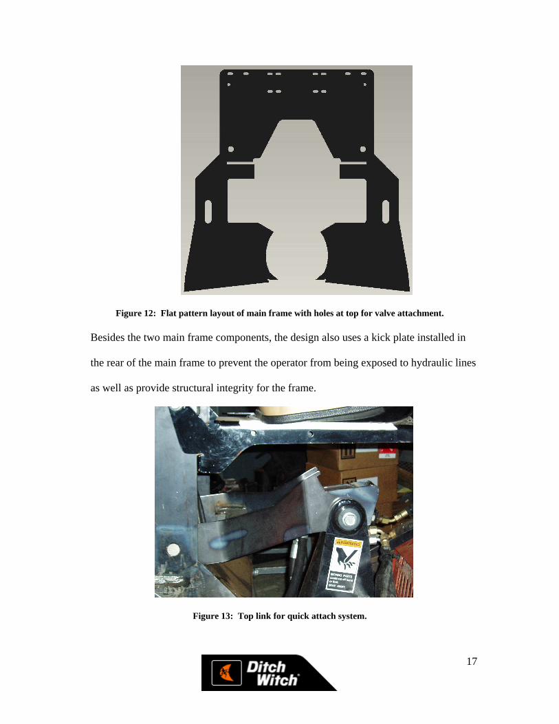
Figure 12: Flat pattern layout of main frame with holes at top for valve attachment.
Besides the two main frame components, the design also uses a kick plate installed in
the rear of the main frame to prevent the operator from being exposed to hydraulic lines
as well as provide structural integrity for the frame.
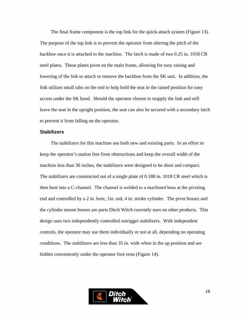
Figure 13: Top link for quick attach system.
18
The final frame component is the top link for the quick-attach system (Figure 13).
The purpose of the top link is to prevent the operator from altering the pitch of the
backhoe once it is attached to the machine. The latch is made of two 0.25 in. 1018 CR
steel plates. These plates pivot on the main frame, allowing for easy raising and
lowering of the link to attach or remove the backhoe from the SK unit. In addition, the
link utilizes small tabs on the end to help hold the seat in the raised position for easy
access under the SK hood. Should the operator choose to reapply the link and still
leave the seat in the upright position, the seat can also be secured with a secondary latch
to prevent it from falling on the operator.
Stabilizers
The stabilizers for this machine use both new and existing parts. In an effort to
keep the operator’s station free from obstructions and keep the overall width of the
machine less than 36 inches, the stabilizers were designed to be short and compact.
The stabilizers are constructed out of a single plate of 0.188 in. 1018 CR steel which is
then bent into a C-channel. The channel is welded to a machined boss at the pivoting
end and controlled by a 2 in. bore, 1in. rod, 4 in. stroke cylinder. The pivot bosses and
the cylinder mount bosses are parts Ditch Witch currently uses on other products. This
design uses two independently controlled outrigger stabilizers. With independent
controls, the operator may use them individually or not at all, depending on operating
conditions. The stabilizers are less than 35 in. wide when in the up position and are
hidden conveniently under the operator foot rests (Figure 14).
19
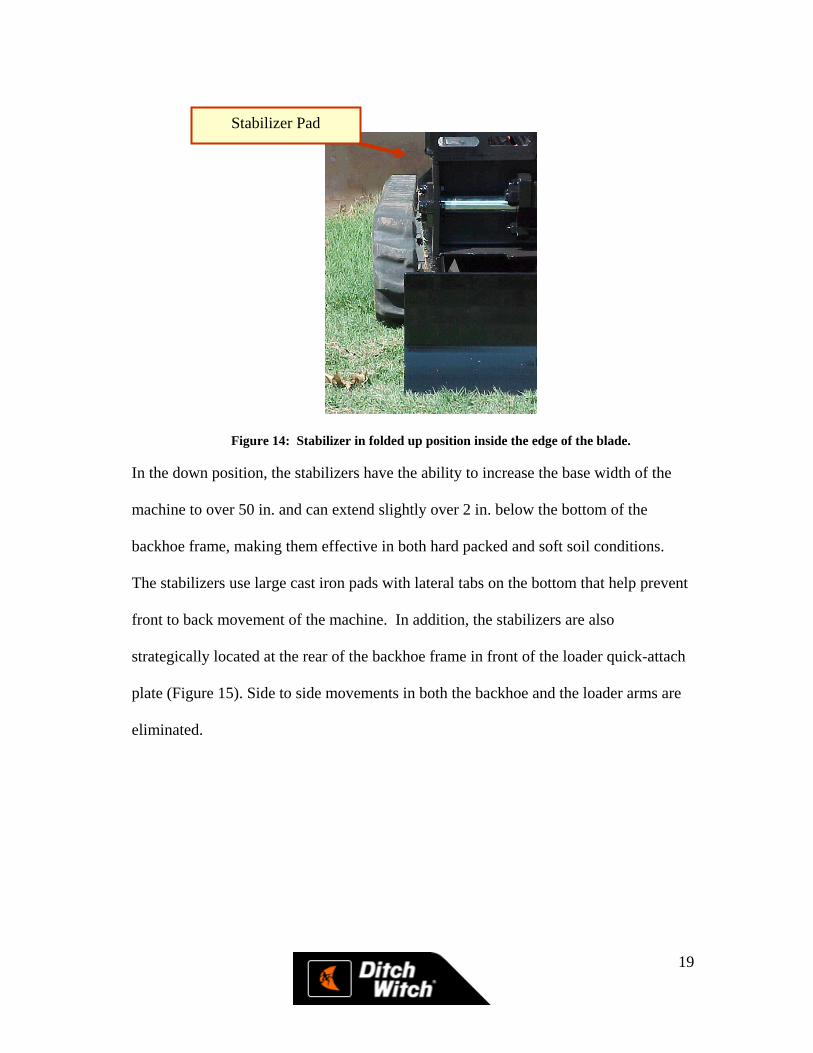
Figure 14: Stabilizer in folded up position inside the edge of the blade.
In the down position, the stabilizers have the ability to increase the base width of the
machine to over 50 in. and can extend slightly over 2 in. below the bottom of the
backhoe frame, making them effective in both hard packed and soft soil conditions.
The stabilizers use large cast iron pads with lateral tabs on the bottom that help prevent
front to back movement of the machine. In addition, the stabilizers are also
strategically located at the rear of the backhoe frame in front of the loader quick-attach
plate (Figure 15). Side to side movements in both the backhoe and the loader arms are
eliminated.
Stabilizer Pad
20
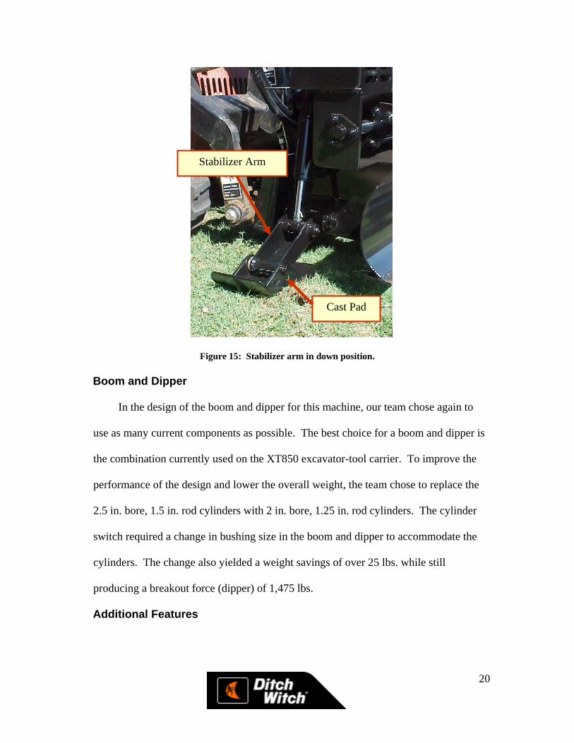
Figure 15: Stabilizer arm in down position.
Boom and Dipper
In the design of the boom and dipper for this machine, our team chose again to
use as many current components as possible. The best choice for a boom and dipper is
the combination currently used on the XT850 excavator-tool carrier. To improve the
performance of the design and lower the overall weight, the team chose to replace the
2.5 in. bore, 1.5 in. rod cylinders with 2 in. bore, 1.25 in. rod cylinders. The cylinder
switch required a change in bushing size in the boom and dipper to accommodate the
cylinders. The change also yielded a weight savings of over 25 lbs. while still
producing a breakout force (dipper) of 1,475 lbs.
Additional Features
Stabilizer Arm
Cast Pad
21
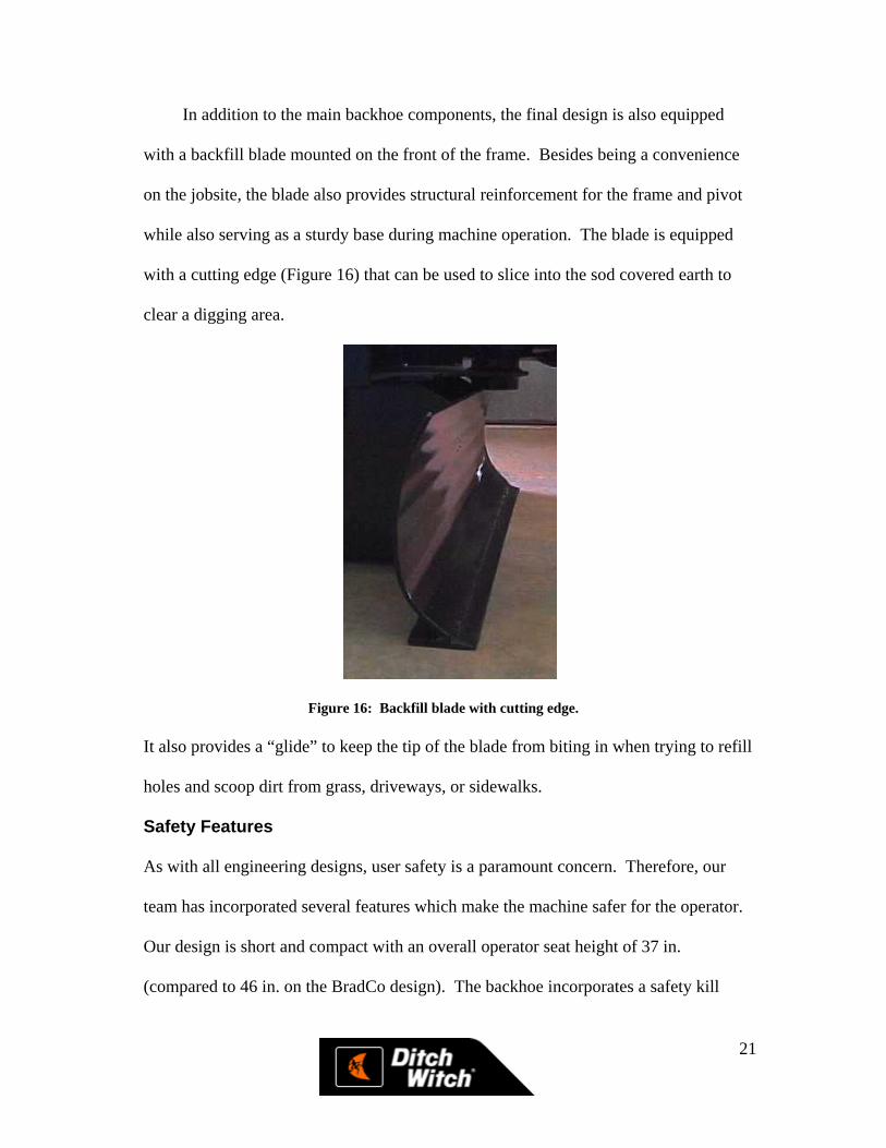
In addition to the main backhoe components, the final design is also equipped
with a backfill blade mounted on the front of the frame. Besides being a convenience
on the jobsite, the blade also provides structural reinforcement for the frame and pivot
while also serving as a sturdy base during machine operation. The blade is equipped
with a cutting edge (Figure 16) that can be used to slice into the sod covered earth to
clear a digging area.
Figure 16: Backfill blade with cutting edge.
It also provides a “glide” to keep the tip of the blade from biting in when trying to refill
holes and scoop dirt from grass, driveways, or sidewalks.
Safety Features
As with all engineering designs, user safety is a paramount concern. Therefore, our
team has incorporated several features which make the machine safer for the operator.
Our design is short and compact with an overall operator seat height of 37 in.
(compared to 46 in. on the BradCo design). The backhoe incorporates a safety kill
22
switch for the engine so the operator can shut the SK500 off while on the backhoe. The
tilt lock also serves as a safety feature in that it does not allow the operator to tilt the
attach plate of the SK500 forward or backward while operating the backhoe. Our
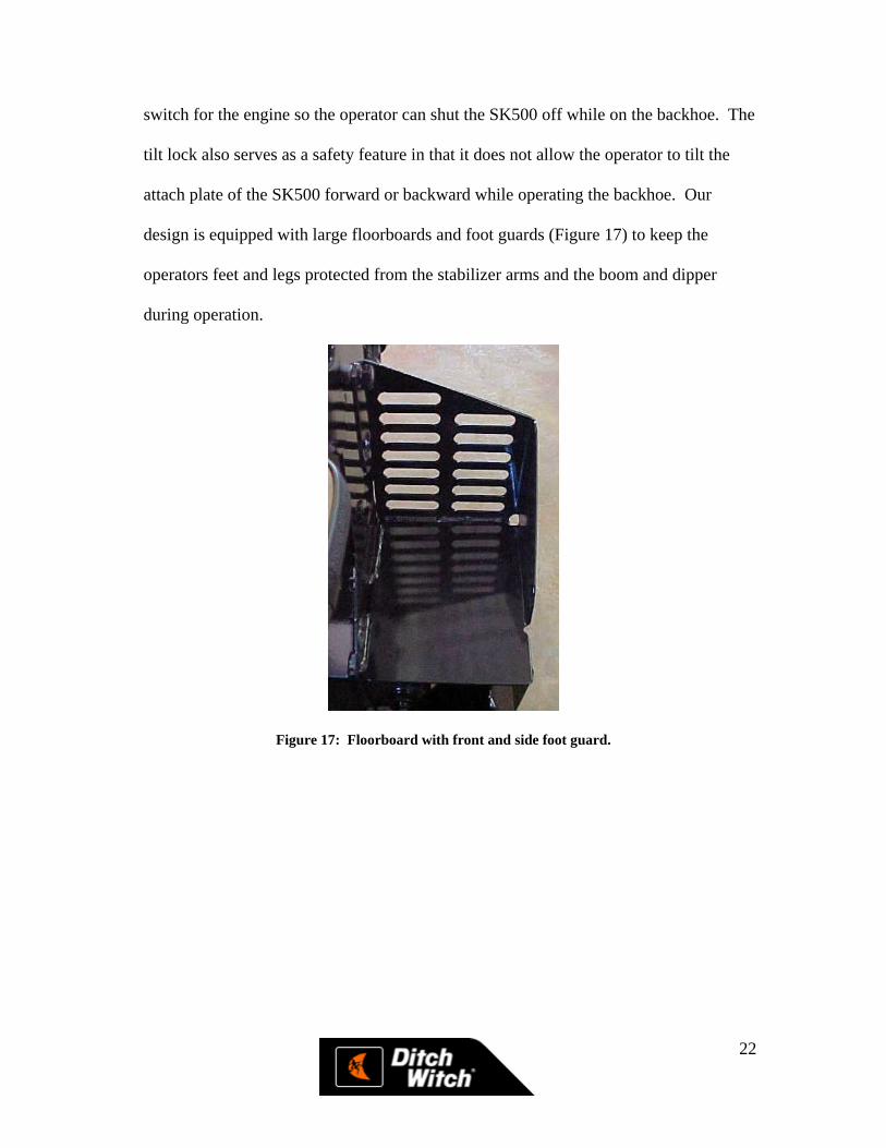
design is equipped with large floorboards and foot guards (Figure 17) to keep the
operators feet and legs protected from the stabilizer arms and the boom and dipper
during operation.
Figure 17: Floorboard with front and side foot guard.
23
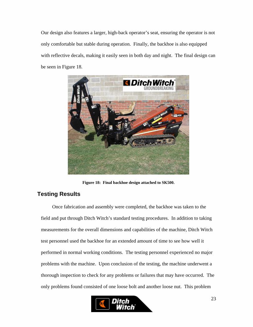
Our design also features a larger, high-back operator’s seat, ensuring the operator is not
only comfortable but stable during operation. Finally, the backhoe is also equipped
with reflective decals, making it easily seen in both day and night. The final design can
be seen in Figure 18.
Figure 18: Final backhoe design attached to SK500. Testing Results
Once fabrication and assembly were completed, the backhoe was taken to the
field and put through Ditch Witch’s standard testing procedures. In addition to taking
measurements for the overall dimensions and capabilities of the machine, Ditch Witch
test personnel used the backhoe for an extended amount of time to see how well it
performed in normal working conditions. The testing personnel experienced no major
problems with the machine. Upon conclusion of the testing, the machine underwent a
thorough inspection to check for any problems or failures that may have occurred. The
only problems found consisted of one loose bolt and another loose nut. This problem
24
was easily remedied by installing Loctite ® on the threads of the bolts; a step that had
been omitted during our initial assembly.
During some of the preliminary design team field testing, a slight problem with
the stabilizer arms was detected. While digging with the machine, our team noticed the
stabilizer arm moved back and forth on the pin connecting the pad to the stabilizer arm.
In addition, the tabs at the end of the stabilizer were flexing under the heavy loads. To
avert this occurrence, a piece of tubing was inserted between the stabilizer sides to
prevent any flexing or bending at the tip of the stabilizer. While this alteration solved
the problem, our team chose to redesign the stabilizer arms to include thicker material.
The 0.188 in. steel lacked the necessary rigidity needed to prevent flexing under load.
As a result, the stabilizers were remade from 0.25 in. steel which eliminated the flexing
problem we detected in testing. The pivot boss attached to the rear of the stabilizer arm
was also redesigned to save weight. In the end, the stabilizer assembly was
approximately two lbs. lighter, while offering more strength and rigidity under loading
conditions.
Further Recommendations
While the prototype performed well in the field, our team the professional testing
personnel from Ditch Witch made comments on possible design refinements. Overall,
testers felt the backhoe performed exceptionally well. Ditch Witch personnel were very
impressed with the redesigned tilt lock mechanism which made it easier for the operator
to not only attach the machine to the SK500, but also perform any maintenance on the
SK500 while the backhoe was attached. Also, testers were pleased with the addition of
25
the stabilizers. They felt the stabilizers offered more stability for the backhoe during
operation, especially in soft soils. The stabilizers also helped eliminate the side-to-side
movements in the loader arms typical during backhoe operation.
One area of concern was the clevis mounts for the stabilizers and the stabilizer
cylinders. Originally, these clevises were manufactured from 0.188 in. steel. While
providing the necessary structural strength, our team felt that upgrading these pieces to
0.25 in. steel (similar to the upgrade on the stabilizer arms) would provide a more rigid
mount and pivot point for the arms. Time constraints prevented the construction of
another prototype unit. However, with the current design and these recommendations,
Ditch Witch would easily be able to implement these upgrades when the machine
undergoes the necessary pre-production process at the Ditch Witch plant.
The current hydraulic valve on the backhoe is another area where improvements could
be made, not for performance, but for cost. The current valve is an in-system valve that
Ditch Witch uses on another backhoe in production (A322). The valve is more than
adequate for our design. However, Ditch Witch also uses another backhoe valve
(A225) which would easily meet our requirements. Unlike the A322 valve, the A225
valve does not contain the additional two sections needed to operate the stabilizers.
Initially, our team had planned to use a small solenoid-operated valve manufactured by
Eaton Vickers. The Eaton Valve, combined with the A225 valve, would allow the unit
to utilize a smaller main valve, saving weight and reducing the overall cost. However,
due to supply problems, Ditch Witch was never able to obtain the valve to test on the
backhoe. After discussing the issue with hydraulic systems designers at Ditch Witch,
26
they felt the valve would be available by mid-summer 2005, making this another viable
alternative for Ditch Witch to consider in pre-production.
An area of considerable cost on the backhoe is the hydraulic components. The
valve and cylinders are very expensive, but necessary components of this design. Ditch
Witch currently manufactures all of its hydraulic cylinders in house making custom
cylinders possible. While all of the cylinders on our machine are adequate, changes to
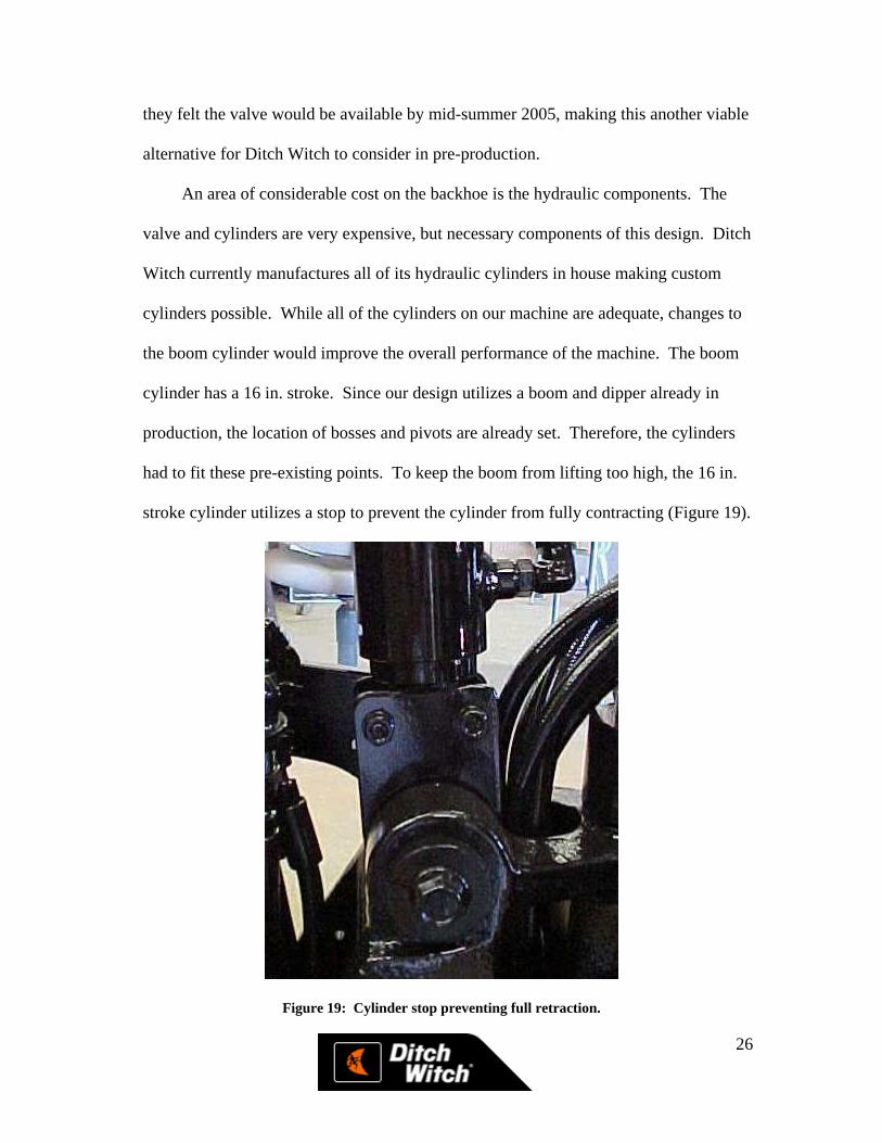
the boom cylinder would improve the overall performance of the machine. The boom
cylinder has a 16 in. stroke. Since our design utilizes a boom and dipper already in
production, the location of bosses and pivots are already set. Therefore, the cylinders
had to fit these pre-existing points. To keep the boom from lifting too high, the 16 in.
stroke cylinder utilizes a stop to prevent the cylinder from fully contracting (Figure 19).
Figure 19: Cylinder stop preventing full retraction.
27
Ditch Witch does not make an 18 in. stroke cylinder with the correct bore and rod
dimensions. However, since Ditch Witch makes its own cylinders, the possibility of
making an 18 in. cylinder exists. By replacing the current 16 in. cylinder with an 18 in.
cylinder, the need for the stop would be eliminated because of the longer retracted
length of the 18 in. cylinder. The boom would be able to extend lower, increasing the
digging depth of the machine by a few more inches.
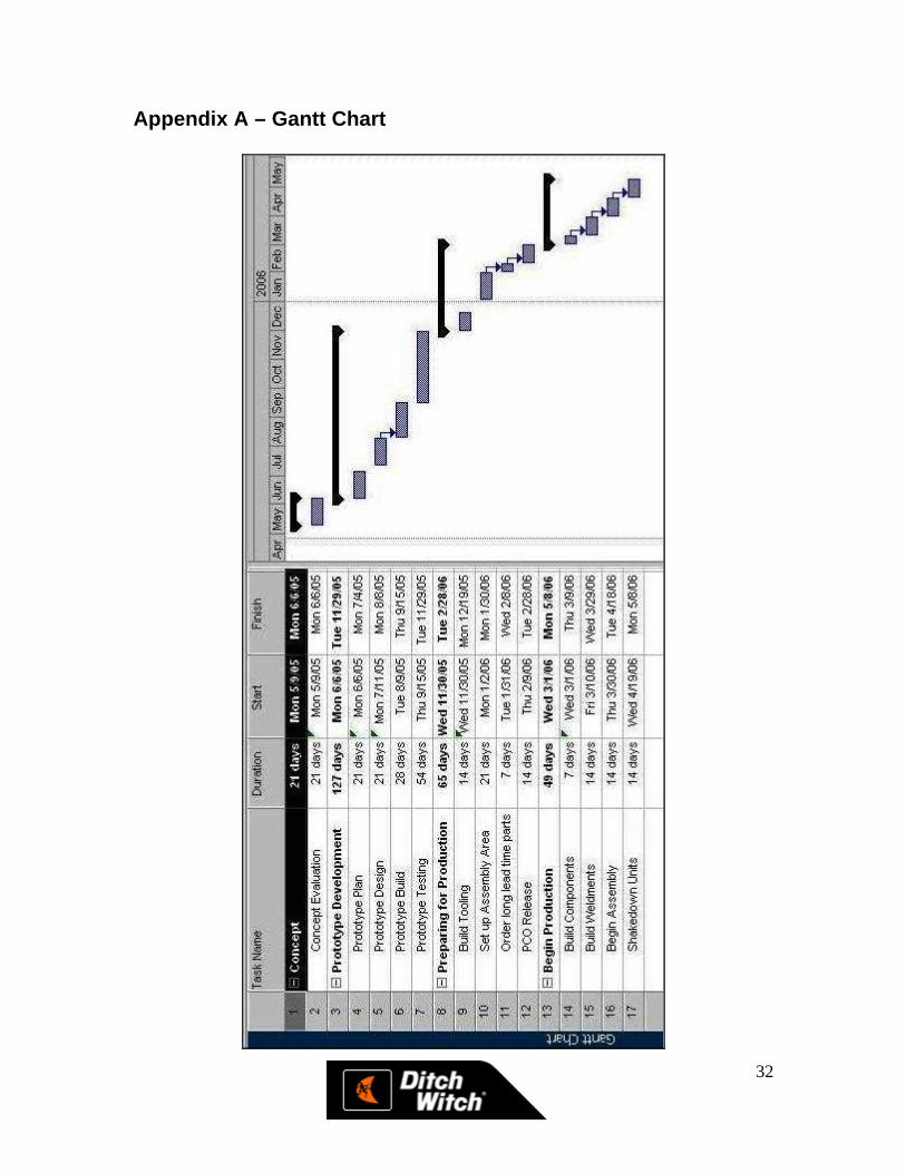
Project Schedule
With the completion of our prototype, our team consulted project managers at
Ditch Witch to understand what it actually takes to implement a product once the initial
design work is complete and the first prototype has been built. Based on their input
concerning such things as manufacturing, testing, component availability, and various
other design factors, our team assembled a projected schedule for implementation of
our design. Based on this schedule, our team feels the backhoe could be in production
by July of 2006, with the earliest possible production date being January 2006. The full
Gantt chart may be reviewed in Appendix A.
Project Budget – Cost Analysis
Early in the design process, our team assembled a projected budget and calculated
the project cost to be approximately $2,800.00. Due to unexpected rises in both energy
and steel costs, these figures were inaccurate and out of date by the time the prototype
was in the production stages.
28
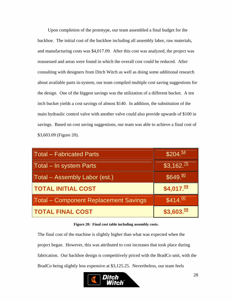
Upon completion of the prototype, our team assembled a final budget for the
backhoe. The initial cost of the backhoe including all assembly labor, raw materials,
and manufacturing costs was $4,017.09. After this cost was analyzed, the project was
reassessed and areas were found in which the overall cost could be reduced. After
consulting with designers from Ditch Witch as well as doing some additional research
about available parts in-system, our team compiled multiple cost saving suggestions for
the design. One of the biggest savings was the utilization of a different bucket. A ten
inch bucket yields a cost savings of almost $140. In addition, the substitution of the
main hydraulic control valve with another valve could also provide upwards of $100 in
savings. Based on cost saving suggestions, our team was able to achieve a final cost of
$3,603.09 (Figure 20).
Total – Fabricated Parts $204.54
Total – In system Parts $3,162.75
Total – Assembly Labor (est.) $649.80
TOTAL INITIAL COST $4,017.09
Total – Component Replacement Savings $414.00
TOTAL FINAL COST $3,603.09
Figure 20: Final cost table including assembly costs.
The final cost of the machine is slightly higher than what was expected when the
project began. However, this was attributed to cost increases that took place during
fabrication. Our backhoe design is competitively priced with the BradCo unit, with the
BradCo being slightly less expensive at $3,125.25. Nevertheless, our team feels
29
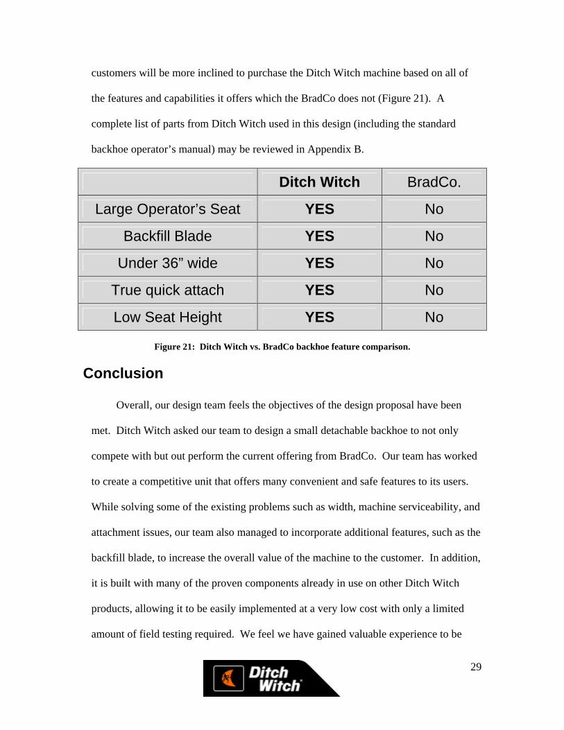
customers will be more inclined to purchase the Ditch Witch machine based on all of
the features and capabilities it offers which the BradCo does not (Figure 21). A
complete list of parts from Ditch Witch used in this design (including the standard
backhoe operator’s manual) may be reviewed in Appendix B.
Ditch Witch BradCo.
Large Operator’s Seat YES No
Backfill Blade YES No
Under 36” wide YES No
True quick attach YES No
Low Seat Height YES No
Figure 21: Ditch Witch vs. BradCo backhoe feature comparison.
Conclusion
Overall, our design team feels the objectives of the design proposal have been
met. Ditch Witch asked our team to design a small detachable backhoe to not only
compete with but out perform the current offering from BradCo. Our team has worked
to create a competitive unit that offers many convenient and safe features to its users.
While solving some of the existing problems such as width, machine serviceability, and
attachment issues, our team also managed to incorporate additional features, such as the
backfill blade, to increase the overall value of the machine to the customer. In addition,
it is built with many of the proven components already in use on other Ditch Witch
products, allowing it to be easily implemented at a very low cost with only a limited
amount of field testing required. We feel we have gained valuable experience to be

30
used later in our engineering careers. By working with the designers and engineers at
Ditch Witch, our team was exposed to many different facets of the design process and
given an overview of how a real-world company completes a design project from idea
conception to finished product.

31
References
Shigley, J. E., Mischke, C. R., Budynas, R. G. Mechanical Engineering Design. New York, N.Y.: McGraw-Hill Company. 2004. 7th Edition.
Womack Machine Supply Co. Fluid Power & Automation Control Designer’s Manual. Dallas, TX. 1999. 42nd Edition
32
Appendix A – Gantt Chart

33
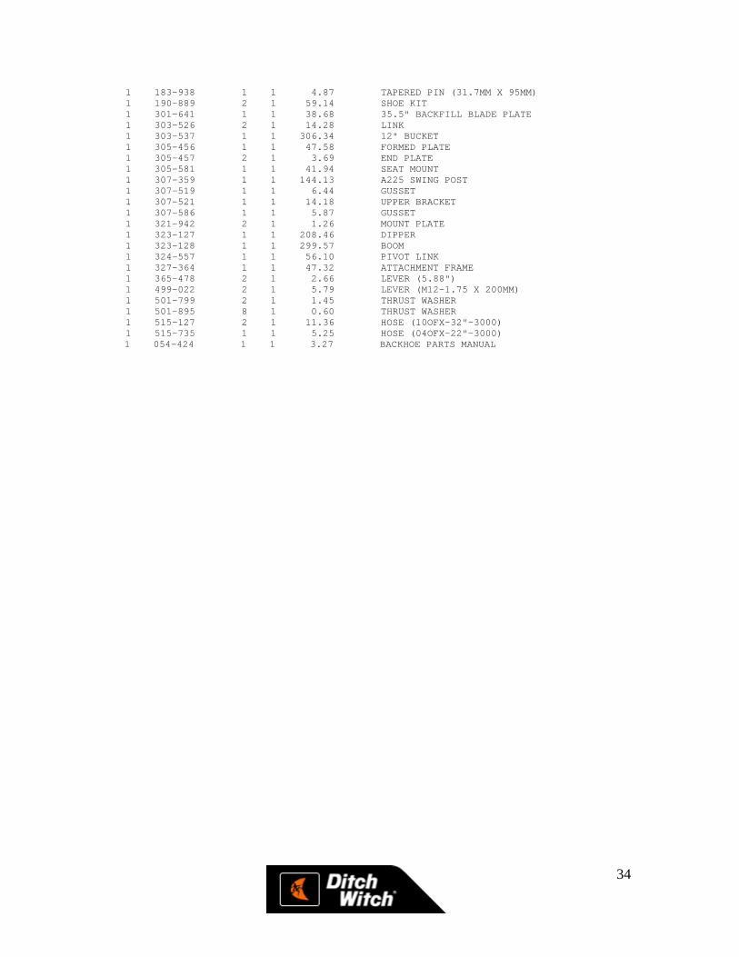
Appendix B – In system parts list
COSTING INDENTED EXPLOSION FOR 000000 4/14/2005 LEV P/N QTY CD COST DESCRIPTION 000000 1 0 $3,162.75 SPECIAL BOM 1 105-089 4 1 0.00 LOCKNUT (5/16-NC) 1 105-286 4 1 0.00 BOLT (3/8-NC X 1-3/4") 1 105-398 2 1 0.33 WASHER (1/2") 1 105-880 4 1 0.00 SHLD BLT (3/8" X 2", 5/16-NC) 1 106-098 2 1 1.38 FLG BOLT (3/4-NC X 2", GD8) 1 106-109 2 1 0.19 WASHER (.780") 1 106-469 2 1 0.00 FLG SCREW (M12-1.75 X 30MM) 1 106-470 1 1 0.00 FLG SCREW (M16-2.0 X 40MM) 1 106-709 6 1 0.00 FLG LK NUT (M12-1.75) 1 107-066 4 1 0.00 LOCKNUT (1-NC, GD8) 1 107-459 1 1 2.96 CABLE GUIDE BOLT 1 107-565 6 1 0.00 FLG LK SCREW (M12-1.75 X 40MM) 1 110-838 2 1 12.21 LONG CHAIN CLEVIS 1 115-003 1 1 0.00 ZERK (1/4-NF, STR) 1 115-012 2 1 0.00 ZERK (04N) 1 115-426 1 1 31.61 SEAT 1 117-412 1 1 1.62 ABRASION SLEEVE (1.00" X 34") 1 117-607 1 1 1.17 ABRASION SLEEVE (1.00" X 21") 1 117-713 1 1 3.05 ABRASION SLEEVE (1.00" X 76") 1 117-718 1 1 1.70 ABRASION SLEEVE (1" X 36") 1 117-993 1 1 1.19 ABRASION SLEEVE (1.00" X 23") 1 118-062 1 1 2.45 ABRASION SLEEVE (1.00" X 62") 1 125-177 2 1 3.08 COMPOSITION BUSHING (1.250") 1 125-444 2 1 2.71 THRUST WASHER (1.750") 1 125-571 6 1 2.39 FRICTION BEARING 1.25" X 1.0" 1 125-572 2 1 2.38 THRUST WASHER (1.50") 1 125-771 2 1 2.56 COMPOSITION BUSHING (1.25") 1 125-772 2 1 4.12 COMPOSITION BUSHING (1.5") 1 125-799 4 1 3.34 COMPOSITION BUSHING 1 149-059 1 1 546.85 HYDRAULIC CONTROL VALVE 1 151-038 2 1 72.29 CYL (2.0 X 1.0 X 4.0) 1 151-091 2 1 90.43 CYL (2.0 X 1.25 X 16.0) 1 151-208 1 1 359.10 CYL (2.5" X 1.5" X 5.77") 1 151-210 1 1 85.96 CYL (2" X 1.25" X 14") 1 154-220 12 1 0.69 CONNECTOR (04O-06S) 1 154-263 1 1 2.18 CONNECTOR (04S-04O45) 1 154-275 2 1 1.84 BK CONNECTOR (04O-04OBK) 1 154-278 1 1 0.59 CONNECTOR (04S-04O) 1 154-285 2 1 3.65 BK CONNECTOR (04O-04O45BK) 1 154-323 2 1 3.89 CONNECTOR (08S-10O90) 1 154-652 1 1 3.64 HOSE (04OFX-20"-3000) 1 154-668 1 1 4.64 HOSE (04OFX-32"-3000) 1 155-833 2 1 1.02 WIPER SEAL (1.500") 1 157-538 6 1 0.99 WIPER SEAL (1.250") 1 159-833 1 1 7.58 HOSE (04OFX45-73"-3000) 1 159-838 1 1 5.97 HOSE (04OFX45-33"-3000) 1 159-839 1 1 5.24 HOSE (04OFX-60"-3000) 1 170-419 2 1 8.23 LEAF CHAIN (#BL844, 13P) 1 178-223 1 1 8.67 TAPERED PIN (31.75MM X 138MM) 1 178-419 1 1 9.67 TAPERED PIN (38.1MM X 208MM) 1 178-420 1 1 8.73 TAPERED PIN (38.1MM X 178MM) 1 179-024 4 1 5.51 TAPERED PIN (25.4MM X 117MM) 1 179-209 1 1 14.10 TAPERED PIN (38.1MM X 320MM) 1 179-928 2 1 2.96 BUSHING (1.50" ID) 1 179-949 2 1 20.45 GRESABLE TAPRD PIN (1.25X6.85) 1 180-700 2 1 8.93 BUSHING 1 181-974 1 1 1.32 TAPERED INSERT (1.5") 1 181-981 4 1 1.04 TAPERED INSERT (1") 1 181-982 2 1 1.01 TAPERED INSERT (1.25") 1 183-863 3 1 6.13 TAPERED PIN (31.7MM X 128MM) 1 183-893 2 1 11.91 TAPERED PIN (1.250" X 6.250")
34
1 183-938 1 1 4.87 TAPERED PIN (31.7MM X 95MM) 1 190-889 2 1 59.14 SHOE KIT 1 301-641 1 1 38.68 35.5" BACKFILL BLADE PLATE 1 303-526 2 1 14.28 LINK 1 303-537 1 1 306.34 12" BUCKET 1 305-456 1 1 47.58 FORMED PLATE 1 305-457 2 1 3.69 END PLATE 1 305-581 1 1 41.94 SEAT MOUNT 1 307-359 1 1 144.13 A225 SWING POST 1 307-519 1 1 6.44 GUSSET 1 307-521 1 1 14.18 UPPER BRACKET 1 307-586 1 1 5.87 GUSSET 1 321-942 2 1 1.26 MOUNT PLATE 1 323-127 1 1 208.46 DIPPER 1 323-128 1 1 299.57 BOOM 1 324-557 1 1 56.10 PIVOT LINK 1 327-364 1 1 47.32 ATTACHMENT FRAME 1 365-478 2 1 2.66 LEVER (5.88") 1 499-022 2 1 5.79 LEVER (M12-1.75 X 200MM) 1 501-799 2 1 1.45 THRUST WASHER 1 501-895 8 1 0.60 THRUST WASHER 1 515-127 2 1 11.36 HOSE (10OFX-32"-3000) 1 515-735 1 1 5.25 HOSE (04OFX-22"-3000) 1 054-424 1 1 3.27 BACKHOE PARTS MANUAL

35
Appendix C – Component Drawings