design of a lightweight radar mastpublications.lib.chalmers.se/records/fulltext/134453.pdf ·...
TRANSCRIPT
Design of a lightweight radar mast
Master’s Thesis in the Master’s programme Solid and Fluid Mechanics and the Master’s programme Product Development
GUSTAV BERG
MATHIAS BROLIN Department of Applied Mechanics Department of Product and Production Development CHALMERS UNIVERSITY OF TECHNOLOGY Göteborg, Sweden 2010 Master’s Thesis 2010:33


MASTER’S THESIS 2010:33
Design of a lightweight radar mast
Master’s Thesis in the Master’s programme Solid and Fluid Mechanics and the Master’s programme Product Development
GUSTAV BERG
MATHIAS BROLIN
Department of Applied Mechanics Department of Product and Production Development
CHALMERS UNIVERSITY OF TECHNOLOGY
Göteborg, Sweden 2010

Design of a lightweight radar mast
Master’s Thesis in the Master’s programme Solid and Fluid Mechanics and the Master’s programme Product Development
GUSTAV BERG
MATHIAS BROLIN
© GUSTAV BERG AND MATHIAS BROLIN, 2010
Master’s Thesis 2010:33
ISSN 1652-8557
Department of Applied Mechanics
Department of Product and Production Development
Chalmers University of Technology
SE-412 96 Göteborg
Sweden
Telephone: + 46 (0)31-772 1000
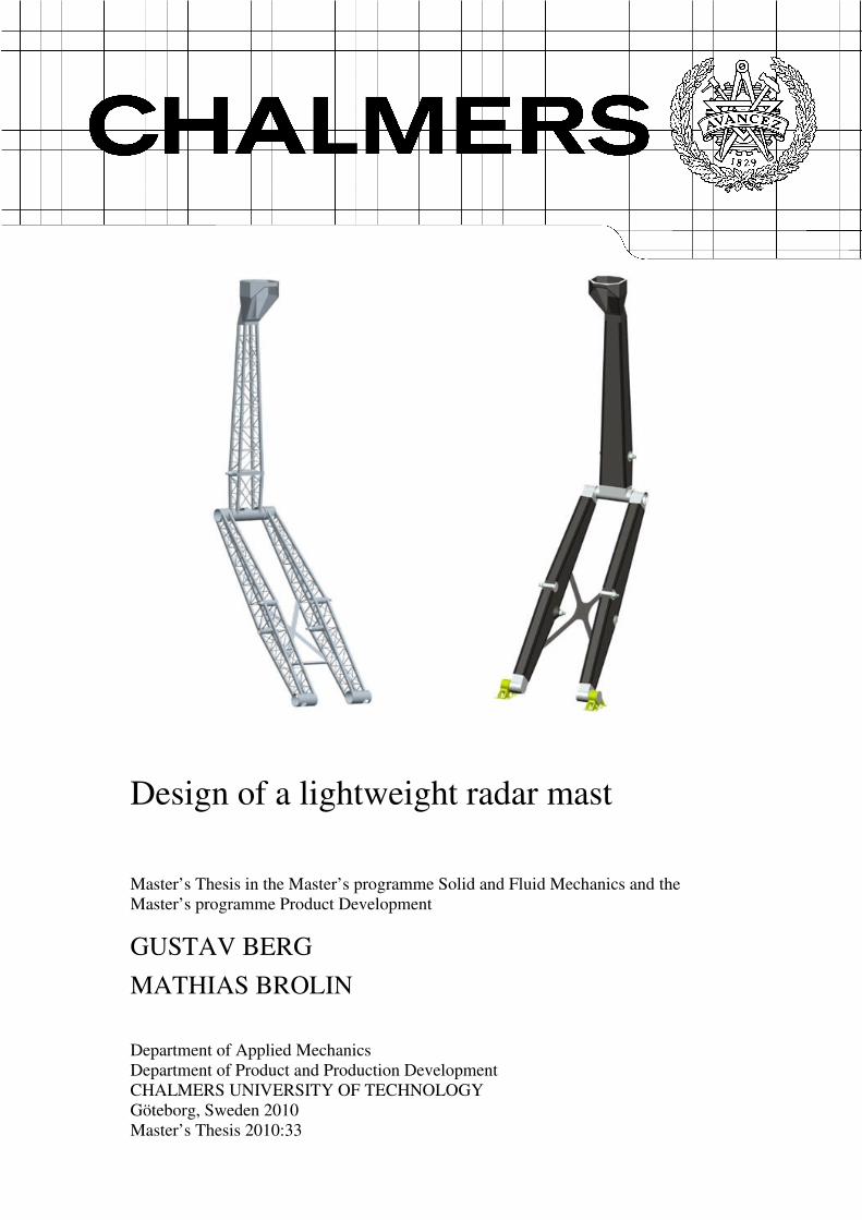
Cover: CAD-models of the two developed mast concepts.
Chalmers Reproservice Göteborg, Sweden 2010

I
Design of a lightweight radar mast Master’s Thesis in the Master’s programme Solid and Fluid Mechanics and the Master’s programme Product Development
GUSTAV BERG AND MATHIAS BROLIN Department of Applied Mechanics Department of Product and Production Development Chalmers University of Technology
ABSTRACT
The aim of the present work has been to develop a lightweight mast for the Saab Giraffe AMB radar system. A reduced weight of the mast lowers the centre of gravity for the whole system and improves the mobility of the carrying vehicle.
Concepts has been developed using a systematic product development approach. To ensure proper benchmarking with the present mast, the lightweight mast was developed to fulfil the same requirements. This includes for example load conditions and environment of use. As a result two final concepts were created, a steel truss mast and a composite mast. Special care has been taken to the manufacturing methods, design principles and mechanics of composite materials.
FE-models of the two mast concepts were developed with the use of MSC Patran/Nastran. The truss mast was mainly modelled with beam elements and the composite mast with shell elements. Size optimization of the models was performed in order to minimize the mass and obtain desired natural frequencies of the mast. The design variables for the truss mast were the beam dimensions and for the composite mast laminate thickness and fibre directions. Optimization of the fibre directions was performed using three different types of carbon fibres, each with different stiffness.
The result showed that no weight reduction was possible with the steel truss mast concept. Optimization resulted in a weight increase of 3%. With the composite mast, weight reduction of up to 53% is possible, depending of fibre stiffness. Optimization of the fibre directions enables higher weight reduction compared to a quasi-isotropic lay-up. Analysis for different combinations of wind loads and gravity shows that no risk of laminate failure or buckling exists.
Final selection of composite material is a balance of weight reduction and material cost. The recommendation is to use high-strength carbon fibres with optimized fibre directions. This gives a weight reduction of 43%.
Keywords: Lightweight design, product development, conceptual design, composite materials, finite element modelling, size optimization.

II
Lättviktskonstruktion av radarmast
Examensarbete inom Tillämpad Mekanik samt Produktutveckling
GUSTAV BERG OCH MATHIAS BROLIN
Institutionen för Tillämpad Mekanik
Institutionen för Produkt- och Produktionsutveckling
Chalmers Tekniska Högskola
SAMMANFATTNING
Syftet med arbetet har varit att utveckla en lättviktskonstruktion för radarmasten i Saab radarsystem Giraffe AMB. En minskad vikt av masten sänker tyngdpunkten för hela systemet och förbättrar mobiliteten för fordonet som systemet är monterat på.
Koncept har utvecklats med hjälp av en systematisk produktutvecklingsprocess. För att säkerställa korrekt jämförelse med den nuvarande masten utvecklades lättviktsmasten för att uppfylla samma krav. Detta omfattar exempelvis lastfall på masten samt miljökrav. Två slutgiltiga koncept skapades, en stålfackverksmast och en kompositmast. Särskild hänsyn har tagits till tillverkning, konstruktion och mekanik för kompositmaterial.
Två FE-modeller av mastkoncepten har utvecklats med hjälp av MSC Patran/Nastran. Fackverksmasten modellerades med balkelement och kompositmasten med skalelement. Storleksoptimering av modellerna utfördes för att minimera vikten och för att erhålla önskade egenfrekvenser. Designvariablerna för fackverksmasten var balkmåtten och för kompositmasten laminattjocklekarna samt fiberriktningarna. Optimering utfördes med tre kolfibertyper av olika styvhet.
Resultatet visade att ingen viktminskning är möjlig med stålfackverksmasten. Optimeringen resulterade i en viktökning på 3%. Med kompositmasten är en viktminskning på upp till 53% möjlig beroende på valet av fiber. Optimering av fiberriktningarna möjliggör högre viktminskning än för ett kvasi-isotropt upplagt laminat. Analyser med hänsyn till olika dimensionerande lastfall visar på låg risk för brott och buckling.
Det slutliga valet av kompositmaterial är en balans mellan viktminskning och materialkostnad. Rekommendationen är att använda ett höghållfast kolfiber med optimerade fiberriktningar, då detta är det mest prisvärda alternativet. Detta ger en viktminskning på 43%.
Nyckelord: Lättviktsdesign, Lättviktskonstruktion, produktutveckling, konceptuell design, kompositmaterial, finit element modellering, storleksoptimering.

CHALMERS, Applied Mechanics, Master’s Thesis 2010:33 III
Contents
ABSTRACT I
SAMMANFATTNING II
CONTENTS III
PREFACE VII
NOTATIONS VIII
1 INTRODUCTION 1
1.1 Background 1
1.2 Aim 2
1.3 Objective 3
1.4 Scope 3
1.5 Method 3
2 SAAB GIRAFFE AMB RADAR SYSTEM 5
2.1 Radar mast 5
2.2 Specification of requirements - lightweight mast 7
2.3 Mechanical performance of the current mast 7
3 MATERIAL SELECTION 10
3.1 Material selection methodology 10
3.1.1 Material requirements 10
3.1.2 Material screening 12
3.2 Metallic materials 13
3.2.1 Aluminium alloys 13
3.3 Composite materials 14
3.3.1 Fibers 14
3.3.2 Matrix 15
3.4 Manufacturing of composite details 17
3.4.1 Manufacturing fundamentals 17
3.4.2 Vacuum moulding 17
3.4.3 Filament winding 18
3.5 Design principles of composites 19
3.5.1 Mechanical joints 21
3.5.2 Bonded joints 22
4 CONCEPT DEVELOPMENT 23
4.1 Concept development methodology 23
4.2 Function analysis 23

CHALMERS, Applied Mechanics, Master’s Thesis 2010:33 IV
4.3 Concept generation 26
4.3.1 Mast concepts 26
4.3.2 Cylinder attachments 29
4.3.3 Knee- and feet joint 31
4.3.4 Mast head 32
4.4 Concept combination 32
4.5 Concept evaluation 34
4.5.1 Evaluation criterions 34
4.5.2 Concept screening 34
4.5.3 Concept scoring 35
4.5.4 Concept selection 37
4.6 Detailed design 37
4.6.1 Truss mast 38
4.6.2 Composite mast 41
5 FE-MODELS AND ANALYSIS 47
5.1 Composite mechanics 47
5.1.1 Anisotropy 47
5.1.2 Stress-strain relation for unidirectional composites 48
5.1.3 Off-axis loading on unidirectional composites 48
5.1.4 Unidirectional ply characteristics 50
5.1.5 Mechanical behaviour of laminated structures 51
5.2 The finite element method 55
5.2.1 Theory 55
5.2.2 Finite element modelling of composites 58
5.3 Dynamic motion of mechanical systems 59
5.4 Buckling 60
5.5 Truss mast FE-model 61
5.5.1 Modelling of the truss mast 61
5.5.2 Initial analysis and modifications 63
5.6 Composite mast FE-model 65
5.7 Optimization 68
5.7.1 Basic structural optimization theory 68
5.7.2 Truss mast optimization 70
5.7.3 Composite mast optimization 71
5.8 Strength and buckling analysis 73
5.8.1 Mast lock analysis 74
6 RESULTS 76
6.1 Truss mast 76
6.1.1 Natural frequencies 76
6.2 Composite mast 78
6.2.1 Natural frequency 78
6.2.2 Strength and buckling analysis 80

CHALMERS, Applied Mechanics, Master’s Thesis 2010:33 V
6.2.3 Mast lock analysis 82
6.2.4 Cost estimation 84
7 DISCUSSION 85
8 CONCLUSIONS 88
8.1 Recommendations 89
9 REFERENCES 90
APPENDIX A: SPECIFICATION OF REQUIREMENTS 92
APPENDIX B: SOLUTIONS FOR MAST SUBSYSTEMS 100
APPENDIX C: PUGH SELECTION MATRIX 105

CHALMERS, Applied Mechanics, Master’s Thesis 2010:33 VI

CHALMERS, Applied Mechanics, Master’s Thesis 2010:33 VII
Preface
In the present work, development of new designs for a lightweight radar mast has been accomplished. The work was carried out at Saab Electronic Defence Systems from January to June 2010. The project was performed at Saab’s Product Development department in Kallebäck and at the Department for Environmental Analysis in Lackarebäck.
The project was executed at the Department of Applied Mechanics and the Department of Product and Production Development, Chalmers University of Technology, Sweden.
We would like to thank the following persons who have supported us during the project:
Peter Svedhem, our supervisor at Saab has supplied us with information about the current mast and directed us throughout the project. Jan Lindahl and Ruoshan Luo have assisted with knowledge and information about the current mast and the software used for the calculations. They have also participated in numerous discussions that have stimulated the work. Henrik Johansson and Jan Ehlersson have assisted with knowledge within the PDM and CAD software’s used at Saab. Our examiner Mats Ander and supervisor Dag Bergsjö at Chalmers have given us continuous support and feedback on the work progress.
Finally, we would like to thank all our wonderful colleagues who have made the work a pleasure.
Göteborg, June 2010
Gustav Berg Mathias Brolin

CHALMERS, Applied Mechanics, Master’s Thesis 2010:33 VIII
Notations
The following notations are used in this paper. The notations applies unless else is stated.
Roman upper case letters
E Young’s modulus of elasticity [GPa]
mE Matrix modulus of elasticity [GPa]
fE Fibre modulus of elasticity [GPa]
lE Modulus of elasticity in the fibre direction [GPa]
tE Modulus of elasticity in the transverse direction [GPa]
G Shear modulus [GPa]
CK1 Fracture toughness [ mMPa ]
gT Glass transition temperature [°C]
X Two bars under a variable denote a matrix
xyS A component in the matrix S , at row x and column y
Roman lower case letters
x One bar under a variable denotes a vector.
Greek lower case letters
γ Shear strain [%]
ε Normal Strain [%]
tε Strain-to-failure [%]
κ Curvature [m-1]
λ Eigenvalue
ν Poisson’s ratio
ρ Density [kg/m3]
yσ Yield strength [MPa]
tσ Tensile strength [MPa]
maxσ Maximum stress [MPa]
τ Shear stress [MPa]
Abbreviations
CAD Computer Aided Design CES Cambridge Engineering Selector CFRP Carbon fibre Reinforced Polymers CNC Computer Numerical Control EMC Electromagnetic Compatibility FEM Finite Element Method IGES Initial Graphics Exchange Specification MS Margin of Safety
CHALMERS, Applied Mechanics, Master’s Thesis 2010:33 1
1 Introduction
1.1 Background
Saab AB was founded in 1937, the company’s primary aim was to meet the need for a domestic military aircraft industry. The development of aircrafts has been important since then and is still one of the major business areas. Today, Saab is a global company with over 13000 employees that serves the market with products and services from the military defence to civil security. The most important markets are Europe, South Africa, Australia and the US.
The extensive transformation on the market has led to an organisation that is more focused on the civil security and with more weight on service supplier solutions. This transition has resulted in a new organisation with operations within five business areas: Aeronautics, Dynamics, Electronic Defence Systems, Security and Defence Solutions, and Support and Services (Saab Group 2010).
Saab Giraffe AMB is one of the products developed by Saab Electronic Defence Systems. The Giraffe was first developed in 1978 and have since then had a series of upgrades. The current system is the third generation and is the one of focus for this project, see Figure 1. The Giraffe AMB is a ground based multi-mission surveillance system for simultaneous monitoring of aircrafts, missiles, helicopters and surface ships. The system has a 360º sensor domain with a surveillance range of 100km or 180km depending on the rotation speed of the antenna. The Giraffe exist in three versions and the focus for this project has been on the truck-mounted system.
• Giraffe AMB (truck-mounted system)
• Sea Giraffe AMB (ship-mounted system)
• Giraffe S (2D version of new generation)
In total over 400 units been sold to over 20 countries. The advantages of the system is simultaneous multi-mission capacity, small target performance in all conditions, high mobility, high survivability and that it is fully self-contained.
To retain their competitive advantage in those areas, continuous improvements in each area is vital. To further improve the mobility it is crucial that the weight of the system is reduced. However, to receive high performance from the antenna it is important that its position over the ground is high. A high position results in fewer disturbances from the surroundings such as ground echoes and gives a more reliable system. This requires a high mast, which results in increased weight of the system and therefore interferes with the desire of improved mobility. Hence, it is vital to investigate new materials and designs that allow a high position of the antenna but with a reduced weight of the system.

CHALMERS, Applied Mechanics, Master’s Thesis 2010:33 2
Figure 1 Saab Giraffe AMB radar system mounted on a truck.
1.2 Aim
The future customer will demand higher mobility of the radar system. By reducing the weight of the system the mobility of the vehicle carrying the system increases. This project aims to find and evaluate designs and materials suitable for reducing the weight of the mast in the Giraffe AMB radar system.
The justification for selecting the mast is that a weight reduction of it gives possibilities for weight reduction of other components as well, since structures like the shelter must be designed to carry the weight of the mast. The high position of the mast results in that a weight reduction of it gives large contributions of lowering the centre of gravity for the whole vehicle. This further improves the mobility, since a lower centre of gravity reduces the risk of an overturn in steep slopes. In addition to this, a lower weight reduces the pressure on the ground from tires and supporting legs which improve the stability in a soft terrain. The reduced weight also lowers the fuel consumption and as a result increases the operating range of the vehicle.
CHALMERS, Applied Mechanics, Master’s Thesis 2010:33 3
1.3 Objective
The broad objective is to ensure that Saab Electronic Defence Systems retain their competitive advantage by offering radar systems with superior mobility. The objective is therefore to present concepts of the mast that is lighter than the existing one. With new materials and a lightweight design, both metals and composites, the weight of the mast is reduced. The goal is to reach a weight reduction of 20% for the metal concept and 50% for composite concept.
1.4 Scope
The scope of the project is limited to the mast. No redesign of other components like shelter or antenna is considered. To enable a benchmark between the existing mast and the final concepts, it is desired to keep all the mechanical interfaces to the surrounding parts at the same positions as for the existing solution. This furthermore limits the possibilities of a new design that differ heavily from the current. The project focuses on the mechanical performance and cost therefore has an underemphasised role. This means that only material cost is estimated. However, manufacturing cost is still considered in the evaluation of concepts.
1.5 Method
The project starts with a study of the present mast and its requirements. This results in a specification of the requirements for the lightweight mast. To ensure the comparability of the new concepts with the present, they are specified for the same conditions. This involves for instance functionality, loads, environment of use and service life.
An inventory of designs and materials for lightweight design is performed to enhance the process of concept development. Manufacturing techniques for composite materials are investigated to determine their influence on the design. The process includes literature studies, interviews and studies of existing and upcoming lightweight products and techniques.
Concept development is then performed with the aim of creating two concepts, one in metal and one in composite. The concept development process starts with brainstorming sessions with the aim of generating a wide range of ideas of how the problem can be solved. Concepts are developed and each one of these concepts is evaluated with engineering selection methods, such as the Pugh selection matrix. The concepts that fail to meet these needs are excluded. Combinations of the remaining concepts are evaluated and those that best fulfil the demands are further developed. These are then narrowed down to two final concepts, using a Kesselring selection matrix.
Detailed design of each concept is performed and the concepts are CAD-modelled using Pro/Engineer. The FE-models are created in the FEM pre-processor Patran, where the models are meshed and boundary conditions and forces are set. In order to

CHALMERS, Applied Mechanics, Master’s Thesis 2010:33 4
further improve the design, a FEM optimization tool is used. The size optimization method is used with the objective of minimizing the weight for given natural frequencies. The FE-models are analyzed with respect to strength and buckling for the same load cases as for the current mast to ensure proper benchmarking. The results from the benchmark are used as a base for the recommendation of future design and material selection of the mast.
CHALMERS, Applied Mechanics, Master’s Thesis 2010:33 5
2 Saab Giraffe AMB radar system
Saab Giraffe AMB is a ground based radar system which is designed to be mounted on a truck, see Figure 1. The system is therefore mobile which makes it possible to place at desired site. The system consists of a shelter where electronics and other components are mounted and from which the system is operated. The usage of ISO corners on the shelter enables the option of exchanging the truck it is mounted on. Four support legs, one in each corner of the shelter, ensure horizontal position when the ground is slanting. The mast with antenna is mounted on top of the shelter, giving it a height of 12 meters from the ground in deployed position. The radar scans the surroundings and provides information to the unit.
A simple cycle when using the radar is:
1. Drive the truck to the site.
2. Enable support legs.
3. Deploy the radar mast.
4. Start the radar and scan the area.
5. Deplete mast.
6. Disable support legs.
7. Drive the truck to a new site.
It is furthermore possible to dismantle the shelter with the radar from the truck, hence free the truck for other missions. The shelter has its own power supply and does not require any power from the truck nor mains to operate.
2.1 Radar mast
The mast is made out of steel and is designed as a two-piece structure with a lower and an upper mast. As mentioned in Section 1.4 it is desired to keep all the mechanical interfaces on the same positions. The mechanical interfaces, see Figure 2, are:
• Attachment of the lower mast to the shelter.
• Lower hydraulic cylinder attachment points to the shelter and lower mast.
• Upper hydraulic cylinder attachment points to upper and lower mast.
• Position and design of the knee joint between upper and lower mast.
• Mast head attachment to upper mast.
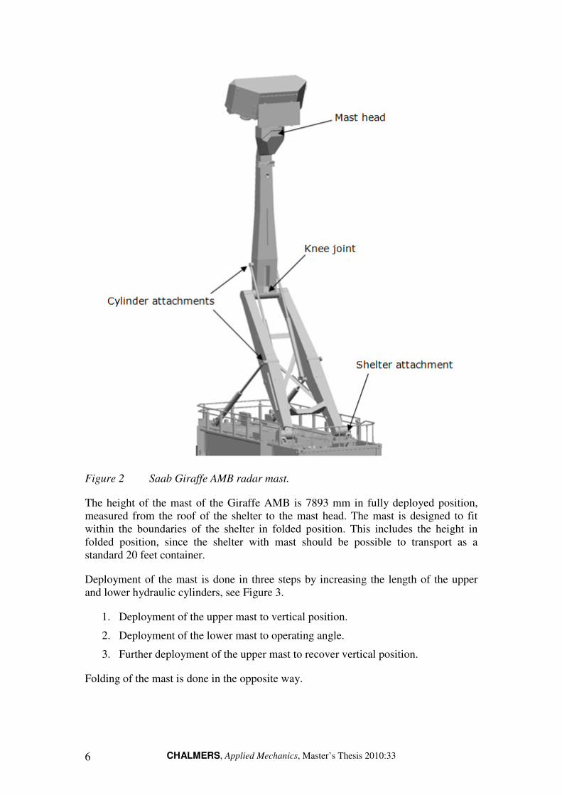
CHALMERS, Applied Mechanics, Master’s Thesis 2010:33 6
Figure 2 Saab Giraffe AMB radar mast.
The height of the mast of the Giraffe AMB is 7893 mm in fully deployed position, measured from the roof of the shelter to the mast head. The mast is designed to fit within the boundaries of the shelter in folded position. This includes the height in folded position, since the shelter with mast should be possible to transport as a standard 20 feet container.
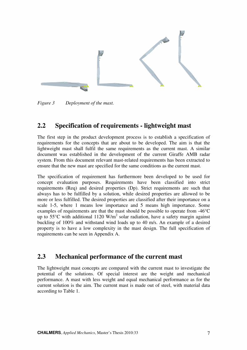
Deployment of the mast is done in three steps by increasing the length of the upper and lower hydraulic cylinders, see Figure 3.
1. Deployment of the upper mast to vertical position.
2. Deployment of the lower mast to operating angle.
3. Further deployment of the upper mast to recover vertical position.
Folding of the mast is done in the opposite way.
CHALMERS, Applied Mechanics, Master’s Thesis 2010:33 7
Figure 3 Deployment of the mast.
2.2 Specification of requirements - lightweight mast
The first step in the product development process is to establish a specification of requirements for the concepts that are about to be developed. The aim is that the lightweight mast shall fulfil the same requirements as the current mast. A similar document was established in the development of the current Giraffe AMB radar system. From this document relevant mast-related requirements has been extracted to ensure that the new mast are specified for the same conditions as the current mast.
The specification of requirement has furthermore been developed to be used for concept evaluation purposes. Requirements have been classified into strict requirements (Req) and desired properties (Dp). Strict requirements are such that always has to be fulfilled by a solution, while desired properties are allowed to be more or less fulfilled. The desired properties are classified after their importance on a scale 1-5, where 1 means low importance and 5 means high importance. Some examples of requirements are that the mast should be possible to operate from -46°C up to 55°C with additional 1120 W/m2 solar radiation, have a safety margin against buckling of 100% and withstand wind loads up to 40 m/s. An example of a desired property is to have a low complexity in the mast design. The full specification of requirements can be seen in Appendix A.
2.3 Mechanical performance of the current mast
The lightweight mast concepts are compared with the current mast to investigate the potential of the solutions. Of special interest are the weight and mechanical performance. A mast with less weight and equal mechanical performance as for the current solution is the aim. The current mast is made out of steel, with material data according to Table 1.

CHALMERS, Applied Mechanics, Master’s Thesis 2010:33 8
Table 1 Material properties for the current mast.
Material Steel EN10025-2:2004, S355J2+N
E 210 GPa
ρ 7800 kg/m3
σy 355 MPa
σt 510 MPa
The current mast has been designed to give sufficient stiffness so that resonance together with the antenna can be avoided (Lindahl 2008). The antenna is mounted on top of the mast and rotates at 57 rpm. The mast will then be subjected to an oscillating force of 1.9 Hz. If the natural frequency of the mast is close to 1.9 Hz, resonance of the mast could occur, leading to relatively large oscillations of it. To avoid resonance the current mast has been designed to have natural frequencies of 2.6 Hz and 3 Hz in the x- and z-direction, see Figure 4. The mass of different parts of the current mast are given in Table 2.
Figure 4 FE-model of the current mast in raised position.

CHALMERS, Applied Mechanics, Master’s Thesis 2010:33 9
Table 2 Masses of different mast parts.
Part Mass [kg]
Antenna unit 560
Cylinders ( 4 x 69 kg ) 276
Bearings ( 4 x 10 kg ) 40
Lower mast attachments 43.8
Lower cylinder attachments 10.1
Lower mast 421
Upper mast 275
Total mass 1626
Besides the natural frequency the current mast is dimensioned with respect to strength and buckling. Analysis with dimensioning load cases has been performed with the mast in fully raised, partly raised and completely lowered position. Wind load of 40 m/s and gravity forms static load cases. The dimensioning load cases for the mast are given below and illustrated in Figure 5.
Figure 5 Wind loads on the mast in fully raised position.
Fully raised condition
1. Wind load 40 m/s in +x direction + gravity.
2. Wind load 40 m/s in -x direction + gravity.
3. Wind load 40 m/s in z direction + gravity.
Partly lowered condition
1. Wind load 40 m/s in +x direction + gravity.
Entirely lowered position
1. Gravity.

CHALMERS, Applied Mechanics, Master’s Thesis 2010:33 10
3 Material selection
3.1 Material selection methodology
In order to develop concepts for the design of the mast, a couple of suitable materials have to be selected. The objective is, as mentioned earlier, to design a lightweight mast utilizing composites and metals. Especially composites are of interest, since some of them have high potential of reducing the weight and are used in some of Saabs other products. Still the material selection processes has to be carried out. This is to assure which composites and metals that are suitable for the design and fulfills the requirements.
The material selection process starts with translation of the design requirements to identify what constraints they impose on the material choice, see Figure 6. The next step is to screen for materials that fulfill the constraints and rank them with the use of performance indices. Once a certain material type is chosen, detailed study of the material is done to get further information of how this material type can be used in the design. This includes aspects like manufacturing methods and design principles (Ashby 2005).
Figure 6 The four steps in the material selection process (Ashby 2005).
3.1.1 Material requirements
The first step in the material selection process is to screen the material space for suitable materials. A full specification of requirements has been established for the lightweight radar mast (Appendix A). The specification of requirements implies
CHALMERS, Applied Mechanics, Master’s Thesis 2010:33 11
constraints on the material. A material must fulfil these constrains in order to be a possible candidate. The constraints used for material screening are listed below.
Strength
The material must have sufficient strength to:
• Support the weight of the antenna unit.
• Withstand loads from wind of 40 m/s.
Local high stress concentration may be present in the structure. A minimum value of σy =100 MPa is set as a demand on the material to avoid a bulky structure that may interfere with other components.
Stiffness
• High stiffness is required to receive desired stiffness of the structure and to avoid a voluminous design, E ≥ 40 GPa.
Toughness
• Must have sufficient toughness to withstand rough treatment, manual ice
removal etc. Minimum K1C = 10 .mMPa
Thermal properties
• Maximum service temperature: 55°C +1120 W/m2 solar radiation. This gives a surface temperature of around 110°C.
• Minimum service temperature: -46°C.
Environmental properties
• Withstand outdoor exposure, such as to rain, snow and hail.
• High resistance against UV radiation.
• Chemical exposure: Withstand exposure to de-icing liquids, alcohol, paraffin oil, weapon grease, petroleum, hydraulic- and engine fluid and C-battle agents.
Health consideration
• Material should not be hazardous to personnel, property or environment.
Fire resistance
• Material should not be inflammable.
Lifetime
• No degradation of the material should occur during the design lifetime of 20 years. This includes corrosion and UV-degradation.

CHALMERS, Applied Mechanics, Master’s Thesis 2010:33 12
3.1.2 Material screening
In order to screen for suitable materials, the material selection software Cambridge Engineering Selector is used. The software enables the use of performance indices to compare different materials. Since the mast can be seen as a beam loaded in bending and compression, the relevant performance indices for a light and stiff material are (Ashby 2005):
ρ
ρ
EC
EC
=
=
2
1
(1)
Maximizing C1 gives high lightweight performance in pure tensile load and C2 in pure bending. Figure 7 shows a plot of stiffness versus density, this is called an Ashby chart. In an Ashby chart a line of constant slope, according to Equation 1, can be plotted. All materials along a certain line are equal in lightweight performance. Translating the line upwards in the diagram gives materials with better lightweight performance.
Figure 7 Young's modulus versus density (Ashby 2005).
From Figure 7 it is concluded that foams, natural materials, technical ceramics, composites and metals have potential for high lightweight performance.

CHALMERS, Applied Mechanics, Master’s Thesis 2010:33 13
Foams and natural materials have low density, but also low strength and stiffness. Design utilizing those materials would require large dimensions to achieve the desired stiffness and strength. Neither do they meet the requirements on service temperature and environmental properties. Technical ceramics are stiff and strong, but also brittle and will fracture easily. Among the metallic materials, beryllium alloys have high lightweight performance. Beryllium is however health hazardous and very expensive. Magnesium alloys have drawbacks in their environmental properties. They creep at moderately low temperatures, and their corrosion properties are poor. Titanium has extremely high corrosion resistance but its stiffness to density performance is average, it is also expensive and difficult to machine. From Ashby´s diagram and according to Equation 1 it can be concluded that the aluminum alloys and carbon fibre reinforced epoxy has high lightweight potential. They also fulfill the temperature and chemical resistance. The remaining materials with the best lightweight performance according to Equation 1 are:
• Carbon Fiber Reinforced Polymers (CFRP).
• Aluminum alloys.
However, for structures submitted to pure tensile and compression loads, steel is preferable instead of aluminum since their merit index for C1 is higher. Structures with a high degree of such loads are truss structures.
The next step is now to perform a detailed study of the selected materials. There exist a variety of different CFRP composites and aluminum alloys. The detailed study aims to find information about the materials. Of interest are the mechanical properties, design considerations and manufacturing techniques.
3.2 Metallic materials
In this section some general properties for aluminium alloys will presented and a list with some common applications can be seen in the end. Detailed information about steels is excluded since the steel in the current solution in that case will be used.
3.2.1 Aluminium alloys
Aluminium is the second most commonly used metal after steel for mechanical designs. The usage continuously increase, partly as a result of the strive for lower weight on products to increase their performance. The material is characterized by low density 2,7g/cm3, good formability and machinability, high thermal conductivity and relatively high corrosion resistance. Aluminium can be hardened with strengths up to 350 MPa and some special alloys have even higher strength.
Since materials like stainless steel or copper are nobler than aluminium galvanic corrosion can occur. Contact with those materials should therefore be avoided. However, a reinforced oxide layer improves the resistance against galvanic corrosion since it functions as an electric isolator. This enables the usage of for instance,

CHALMERS, Applied Mechanics, Master’s Thesis 2010:33 14
aluminium and carbon fibre together, as long as the oxide layer separates the materials. Furthermore, aluminium has a maximum service temperature of about 200ºC, this limit is however lower for some of the alloys (Johannesson 2004). It should also be mentioned that the production of aluminium consumes high amounts of energy.
The aluminium materials are generally divided into series depending on their alloying elements. A brief description of properties and applications of the different aluminium series can be seen in Table 3.
Table 3 Aluminium series with some selected properties and applications
(Norell 2009).
Series Properties Example of applications
1000 Fe-Si-alloys
Low strength, good formability and electrical conductivity plus good corrosion properties.
Packaging, cooking and electrical cables.
2000 Mn-alloys
Very high strength but poor welding and corrosion properties.
Airplanes, machine parts, screws and rivets.
3000 Cu-alloys
Medium strength, good formability and good corrosion properties.
Tubes and casseroles, heat exchangers and coolers.
4000 Si-alloys
Not used extensively, though sometimes in forged components and welding wire.
Common composition for cast alloys.
5000 Mg-alloys
High strength and good corrosion resistance. An Mg content >3% is used to resist sea water.
Typical sheet metal used in buildings and boats.
6000 Mg-Si-alloys
High strength, excellent corrosion properties, and good welding properties.
Extruded profiles, both with or without anodization.
7000 Zn-Mg-Cu-alloys
Very high strength alloys, high corrosion resistance and good welding properties.
Typically in welded structures submitted to high loads.
3.3 Composite materials
The composite material can be defined as a combination of two or more materials with a distinct interface between them (Donaldson 2010). The properties of the composite are a balance of the constituents, which usually consist of reinforcements in a continuous matrix. The reinforcement can be in form of particles, flakes, short fibres or continuous fibres and woven fabrics (Gay 2003).The matrix is softer than the fibre and its function is to distribute the fibres and transmits the load to them. The focus will lie on the continuous fibres since they provide superior strength and stiffness to the material.
3.3.1 Fibers
Some fibres that are commonly used in composite materials are (Gay 2003):
• Glass.
• Aramid (Kevlar).
• Carbon.
CHALMERS, Applied Mechanics, Master’s Thesis 2010:33 15
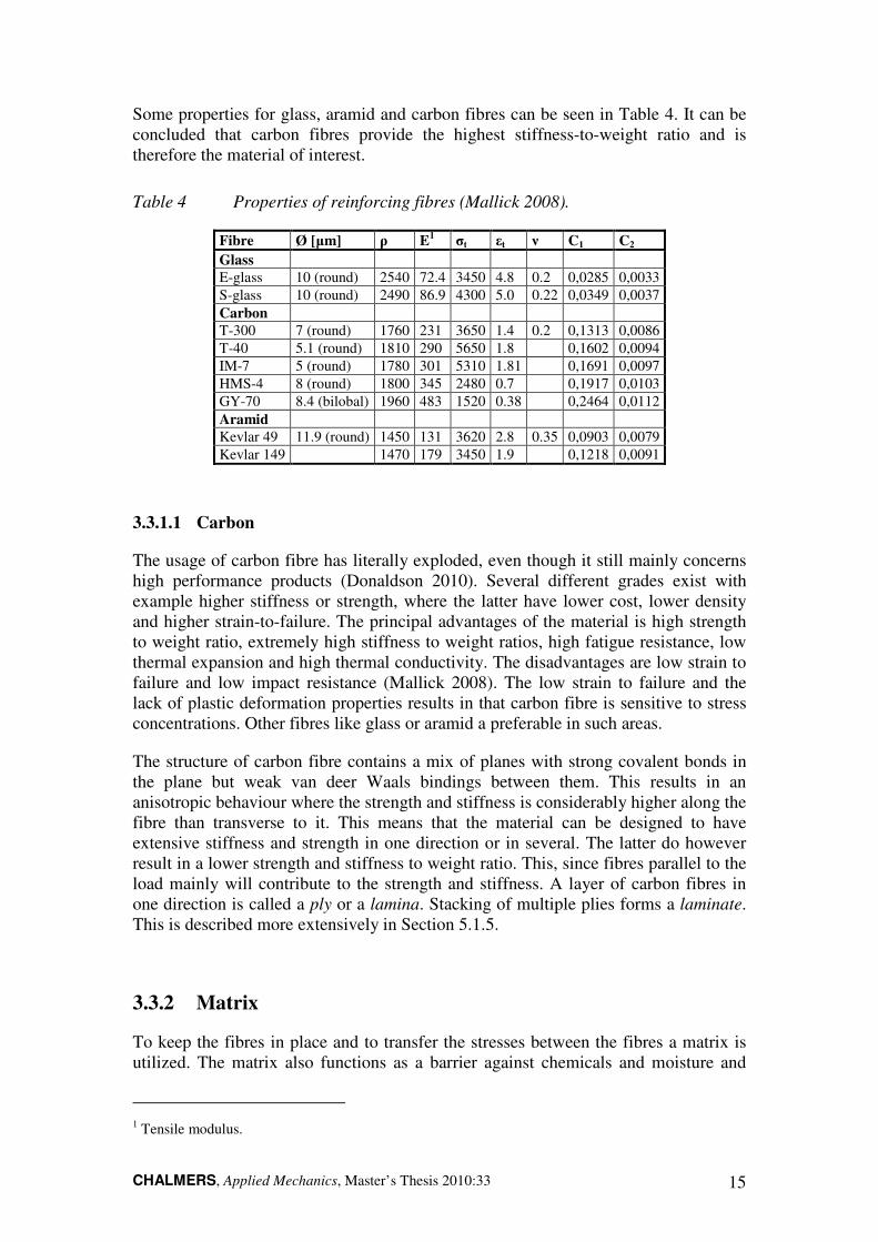
Some properties for glass, aramid and carbon fibres can be seen in Table 4. It can be concluded that carbon fibres provide the highest stiffness-to-weight ratio and is therefore the material of interest.
Table 4 Properties of reinforcing fibres (Mallick 2008).
Fibre Ø [µm] ρ E1 σt εt ν C1 C2
Glass
E-glass 10 (round) 2540 72.4 3450 4.8 0.2 0,0285 0,0033
S-glass 10 (round) 2490 86.9 4300 5.0 0.22 0,0349 0,0037
Carbon
T-300 7 (round) 1760 231 3650 1.4 0.2 0,1313 0,0086
T-40 5.1 (round) 1810 290 5650 1.8 0,1602 0,0094
IM-7 5 (round) 1780 301 5310 1.81 0,1691 0,0097
HMS-4 8 (round) 1800 345 2480 0.7 0,1917 0,0103
GY-70 8.4 (bilobal) 1960 483 1520 0.38 0,2464 0,0112
Aramid
Kevlar 49 11.9 (round) 1450 131 3620 2.8 0.35 0,0903 0,0079
Kevlar 149 1470 179 3450 1.9 0,1218 0,0091
3.3.1.1 Carbon
The usage of carbon fibre has literally exploded, even though it still mainly concerns high performance products (Donaldson 2010). Several different grades exist with example higher stiffness or strength, where the latter have lower cost, lower density and higher strain-to-failure. The principal advantages of the material is high strength to weight ratio, extremely high stiffness to weight ratios, high fatigue resistance, low thermal expansion and high thermal conductivity. The disadvantages are low strain to failure and low impact resistance (Mallick 2008). The low strain to failure and the lack of plastic deformation properties results in that carbon fibre is sensitive to stress concentrations. Other fibres like glass or aramid a preferable in such areas.
The structure of carbon fibre contains a mix of planes with strong covalent bonds in the plane but weak van deer Waals bindings between them. This results in an anisotropic behaviour where the strength and stiffness is considerably higher along the fibre than transverse to it. This means that the material can be designed to have extensive stiffness and strength in one direction or in several. The latter do however result in a lower strength and stiffness to weight ratio. This, since fibres parallel to the load mainly will contribute to the strength and stiffness. A layer of carbon fibres in one direction is called a ply or a lamina. Stacking of multiple plies forms a laminate. This is described more extensively in Section 5.1.5.
3.3.2 Matrix
To keep the fibres in place and to transfer the stresses between the fibres a matrix is utilized. The matrix also functions as a barrier against chemicals and moisture and
1 Tensile modulus.

CHALMERS, Applied Mechanics, Master’s Thesis 2010:33 16
protects the fibres against mechanical degradation such as abrasion (Mallick 2008). Important properties of the matrix are the adhesion to the fibre, temperature properties, processing, dimension stability, flammability, interlaminar strength and stiffness. About 75% of all the composites use thermosets as resin, however the use of thermoplastics are gradually increasing. The low production volume of the mast, about ten units per year and the use of continuous fibres motivates the usage of a thermoset resin. Some of the commonly used thermosets are epoxy, polyester and vinyl ester. Nevertheless, polyester and vinyl ester has disadvantages like high volumetric shrinkage and low heat deflection temperatures. This together with epoxies superior adhesions to carbon fibre motivates the use of it (Mallick 2008).
3.3.2.1 Epoxy
The first large application area for epoxy was the aerospace industry. The relatively high material and design cost made it troublesome to apply in standard applications. Epoxy has high strength, wets out exceptionally well, excellent adhesion to fibres, low shrinkage, good chemical resistance and large modification possibilities (Ryshwalski 2009). Some mechanical properties of epoxy are given in Table 5.
Table 5 Typical mechanical properties of a cast epoxy resin at 23ºC (Mallick
2008).
Density [kg/m3] 1200 – 1300
Yield strength [MPa] 55 – 130
Young´s modulus [GPa] 2.75 – 4.1
Strain-to-failure [%] 0.2 – 0.33
Cure shrinkage [%] 1 – 5
Epoxy is commonly used as an adhesive in a wide range of applications. Some typical environmental properties for an epoxy resin are shown in Table 6. The properties of the material highly depend on the amount of cross-links between the polymer chains. Increased cross-linkage results in higher stiffness, glass transition temperature-, thermal stability and chemical resistance. In addition, it results in reduced strain-to-failure and fracture toughness. The disadvantages of the material are the relatively high cost and long cure time (Mallick 2008).
Table 6 Environmental properties for a carbon fibre epoxy (Cambridge
Engineering Selector).
Maximum service temperature [°C] 140 – 220
Minimum service temperature [°C] -123 – -37
Glass transition temperature [°C] 100 – 180
Flammability Slow burning
Water absorption @ 24 hrs [%] 0,036 – 0,0525
Water resistance Excellent
Organic solvent resistance Limited use
Weak acids Acceptable
UV radiation resistance Good

CHALMERS, Applied Mechanics, Master’s Thesis 2010:33 17
3.4 Manufacturing of composite details
Composite materials can be manufactured in several ways and each method influences the design and properties of both material and part. Manufacturing methods therefore have a great influence on the conceptual design. Some general manufacturing fundamentals and selected manufacturing methods are described briefly in the following sections.
3.4.1 Manufacturing fundamentals
When a composite is manufactured it is important that the resin is cured correctly, this implies that cross-linkage between the polymer chains take place. This is accomplished with elevated temperature and pressure. A typical cure cycle can be seen in Figure 8. The elevated temperature initiates the chemical reaction and transforms the uncured resin to partly or fully cured condition depending on what is desired. The time for proper curing to take place is called the cure cycle and depends on resin chemistry, catalyst reactivity, cure temperatures and presence of inhibitors or accelerators (Mallick 2008). Higher temperature reduces the time for the curing to take place and lower temperature extends the cure time considerably. The pressure ensures that the high viscous resin penetrates the fibres and plies so that the number of voids can be reduced. A high void content lowers the performance significantly and can lead to severe quality issues. Furthermore, the cure temperature controls Tg of the composite.
Figure 8 A typical two-stage cycle for carbon fibre/epoxy prepreg (Mallick
2008).
3.4.2 Vacuum moulding
The process typically uses pre-impregnated fibres with about 40 wt% resin. During the vacuum moulding process excessive resin, about 10 wt%, flows out the mould through the vacuum pump as a result of the low pressure, see Figure 9. It is important that the film is sealed against the mould to create vacuum so that proper wetting
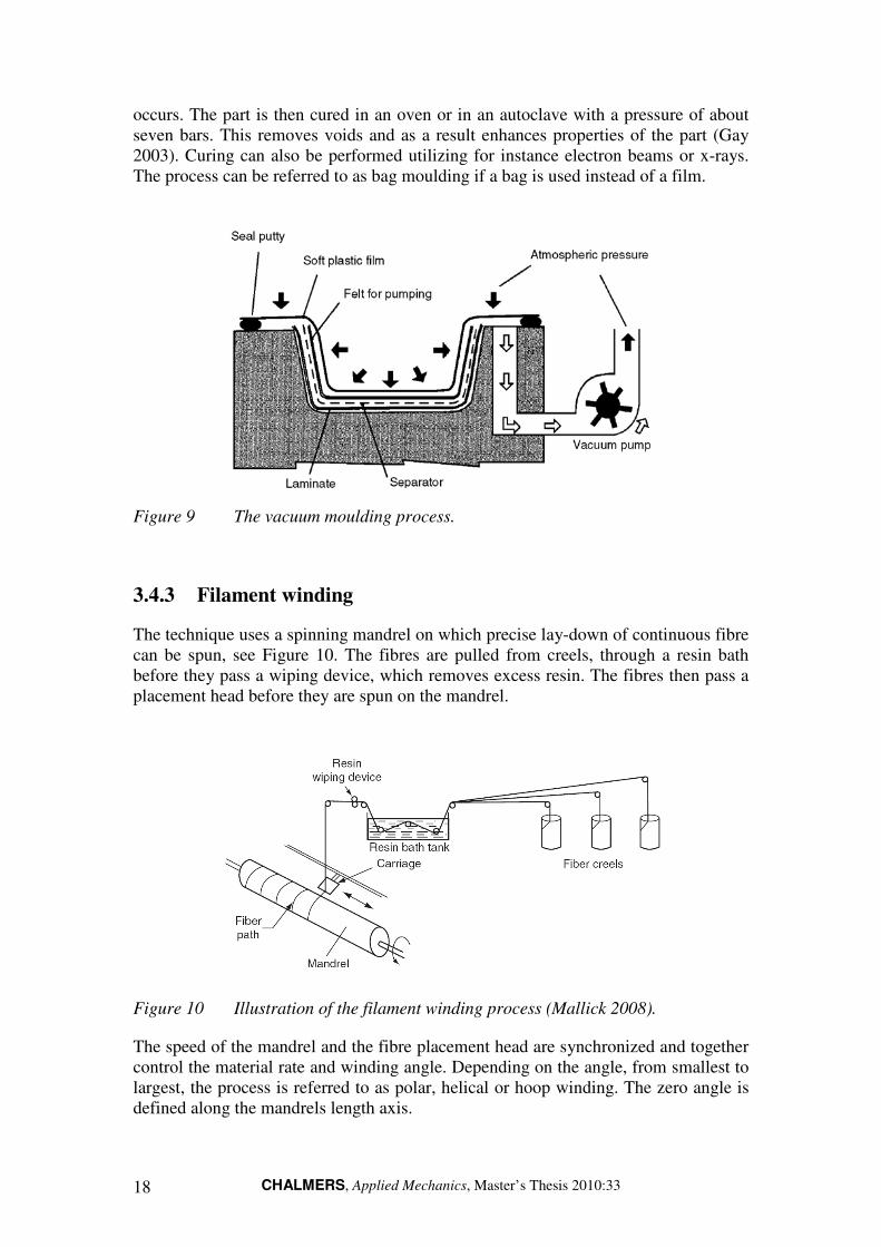
CHALMERS, Applied Mechanics, Master’s Thesis 2010:33 18
occurs. The part is then cured in an oven or in an autoclave with a pressure of about seven bars. This removes voids and as a result enhances properties of the part (Gay 2003). Curing can also be performed utilizing for instance electron beams or x-rays. The process can be referred to as bag moulding if a bag is used instead of a film.
Figure 9 The vacuum moulding process.
3.4.3 Filament winding
The technique uses a spinning mandrel on which precise lay-down of continuous fibre can be spun, see Figure 10. The fibres are pulled from creels, through a resin bath before they pass a wiping device, which removes excess resin. The fibres then pass a placement head before they are spun on the mandrel.
Figure 10 Illustration of the filament winding process (Mallick 2008).
The speed of the mandrel and the fibre placement head are synchronized and together control the material rate and winding angle. Depending on the angle, from smallest to largest, the process is referred to as polar, helical or hoop winding. The zero angle is defined along the mandrels length axis.

CHALMERS, Applied Mechanics, Master’s Thesis 2010:33 19
The filament winding method furthermore enables high material rates and repeatability due to CNC-programming. This results in lower manufacturing cost, which is even more important when a high number of units are produced. The process also allows for high fibre fraction of the part (Donaldson 2010).
The mandrel can have any shape as long as the curvature is not re-entrant since the fibres then lose contact with the mandrel, see Figure 11. However, it is difficult to obtain a high pressure on flat surfaces and it is therefore troublesome to receive a low void content. The fibre used can be pre-impregnated or it can pass a bath of resin, wet winding, before it is spun on the mandrel. The latter method allows for lower cost and is used the most. The technique limits the possible design since the mandrel needs to be removed after the process is finished. Inflatable, dividable or soluble mandrels exist and are used when the design demands it. Soluble mandrels can be made out of sand or plaster where a soluble binder is used. Large designs result in heavy mandrels and may require reinforcement, which raises the cost. The inflatable mandrels are made out of rubber or other elastomeric polymers and are expanded using increased internal pressure. The dividable mandrels can be made in a desired material and can be used as long as the product design allows for disassemble and removal of the mandrel parts.
Figure 11 The left figure is an example of a cross-section that is suitable for
filament winding. The right figure shows a re-entrant cross section
where the fibres lose contact with the mandrel in the corners.
3.5 Design principles of composites
Usage of a composite material in a part affects the overall design, specific design solutions and there are also some precautions that have to be considered. Some of these aspects will be discussed in the following section since they must be taken into consideration in the conceptual design. Special interest in holes and joints has been taken since they often are the source for failures.
When a part is designed using a composite material one must consider the arrangement and dimensions of plies, so that the fibres directions are optimized for the load cases. When interfaces of different materials exist, one must bear in mind that they might have different elongation and may as a result induce stresses. Temperature changes may lead to the same result, since the thermal coefficient of expansion is negative for carbon fibre and Kevlar, while it is positive for glass fibre and metals. The fatigue resistance for composites is considerably higher than for steels and aluminium and is in the same order equal to 90%, 50% and 35% of the static fracture strength (Gay 2003).

CHALMERS, Applied Mechanics, Master’s Thesis 2010:33 20
Furthermore, composites are sensitive for stress concentrations, especially carbon fibre. It is therefore important to have safety factors against uncertainties from (Gay 2003):
• Mechanical properties of fibre and matrix.
• Possible imperfections.
• The fabrication process.
• Aging of the material.
Since stress concentrations are a severe problem it is important to have smooth transitions in the design. This is for example important when increasing or decreasing the number of plies, see Figure 12.
Figure 12 Transition when increasing the number of plies (Gay 2003).
Holes and joints are other sensitive areas since the fibres in the composites cannot experience yield like metals. The otherwise occurring stress relief cannot take place and will therefore result in high stress concentrations, see Figure 13. It is therefore important with increased dimensions around holes and joints to avoid stress concentrations.

CHALMERS, Applied Mechanics, Master’s Thesis 2010:33 21
Figure 13 Stress distributions around a hole and some rules of thumb for material
dimensioning and safety factors (Gay 2003).
3.5.1 Mechanical joints
The strength of mechanical joints differs depending on if it is a pinned or a bolted joint. The latter has a clamping torque which increases the load bearing area, similar to the metal shims, and therefore results in a stronger joint with lower risk of failure. Another way of reducing the risk of failure near a hole is to replace some of the carbon fibres with a material that has higher strain-to-failure, for example glass fibre. Similar behaviour can be achieved by replacing the 0º plies with ±45º plies around the hole.
The holes can be achieved by machining or formed during modelling of the part. The former is preferred since fibre directions and resin distribution may be hard to control. Water-jet and laser are other methods of cutting the material and they have been successful in producing holes with high quality. Below are some general advantages and disadvantages of the usage of mechanical joints together with composites listed (Mallick 2008).
Advantages
• Permit disassembly for repair or replacement of product.
• No surface preparation.
• Easy to inspect.
Disadvantages
• Holes interrupt fibres and may reduce strength.
• Adds weight.
• Potential galvanic corrosion problems between metal and carbon fibres.
CHALMERS, Applied Mechanics, Master’s Thesis 2010:33 22
3.5.2 Bonded joints
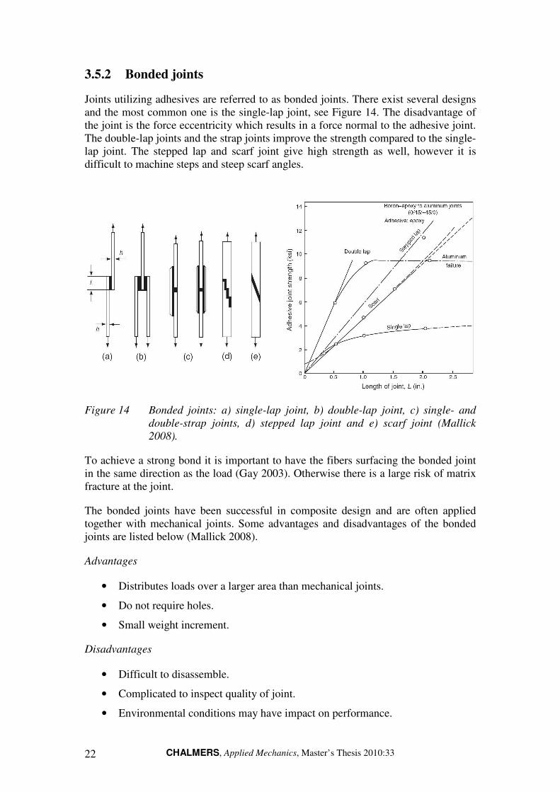
Joints utilizing adhesives are referred to as bonded joints. There exist several designs and the most common one is the single-lap joint, see Figure 14. The disadvantage of the joint is the force eccentricity which results in a force normal to the adhesive joint. The double-lap joints and the strap joints improve the strength compared to the single-lap joint. The stepped lap and scarf joint give high strength as well, however it is difficult to machine steps and steep scarf angles.
Figure 14 Bonded joints: a) single-lap joint, b) double-lap joint, c) single- and
double-strap joints, d) stepped lap joint and e) scarf joint (Mallick
2008).
To achieve a strong bond it is important to have the fibers surfacing the bonded joint in the same direction as the load (Gay 2003). Otherwise there is a large risk of matrix fracture at the joint.
The bonded joints have been successful in composite design and are often applied together with mechanical joints. Some advantages and disadvantages of the bonded joints are listed below (Mallick 2008).
Advantages
• Distributes loads over a larger area than mechanical joints.
• Do not require holes.
• Small weight increment.
Disadvantages
• Difficult to disassemble.
• Complicated to inspect quality of joint.
• Environmental conditions may have impact on performance.

CHALMERS, Applied Mechanics, Master’s Thesis 2010:33 23
4 Concept development
4.1 Concept development methodology
The concepts are developed with the aim of minimizing the weight and fulfilling the specification of requirements for the mast. The specification of requirements can be seen in Appendix A. In this work a systematic approach is used with the aim of finding the best solutions from the two chosen material groups, see Figure 15. The first step is to analyze the functions of all the subsystems of the mast. The result is a function map where the total function is realized by interactions of the subsystems. Using the defined functions new concepts are developed on a sub-system level. These concepts are then combined to form total solutions. By this approach a number of solutions can be developed. Concepts are then evaluated using engineering selection methods. The concept development process used is described in (Johannesson 2004).
Figure 15 The product development process.
4.2 Function analysis
The concept development process starts with performing a functions analysis of the current mast and results in a function map, see Figure 17. Here the function of the total mast is visualized by the interaction of a number of subsystems performing different functions. Unwanted functions are also included, represented by red arrows. Figure 16 shows the current mast with the most important subsystems distinguished.

CHALMERS, Applied Mechanics, Master’s Thesis 2010:33 24
Figure 16 Giraffe AMB mast with subsystems.
Due to the mechanical interface requirement, some subsystems need to be re-used or designed in a similar way as in the current solution.
The subsystems with the largest potential for weight reduction are the lower and upper mast, which currently are heavy steel structures. The closed design also gives a large projected area, and hence a large wind load. Redesign of the upper and lower mast requires new designs of the interfaces to masthead, knee joint and mast feet. Based on the analysis of functions and subsystems it was concluded that the focus for the concept development is the following subsystems:
• Lower and upper mast.
• Stiffeners.
• Hydraulic cylinder attachments.
• Knee and mast feet joints.
• Mast head.

CHALMERS, Applied Mechanics, Master’s Thesis 2010:33 25
Figure 17 Function map for the radar mast. Black arrows represent desired functions and red arrows represent unwanted effects.
CHALMERS, Applied Mechanics, Master’s Thesis 2010:33 26
4.3 Concept generation
From the function map it could be concluded that for instance upper and lower mast takes high wind loads and that the waveguide limits the design. Furthermore, the map gave an increased understanding of the system that supported the concept generation.
To enhance the concept generation process information about lightweight design, materials and design principles was sought in-house and externally. A brief benchmark study of competitors’ radar systems was also performed. Special interest was given to composite design. To enhance the knowledge about this study visits were carried out to Swerea Sicomp and FlexProp AB, two companies working with composite design.
The knowledge gained from these experiences was used during brainstorming sessions that were held to create new possible solutions. Some of the promising solutions created are shown below, including their estimated benefits and drawbacks. The remaining concepts can be found in Appendix B.
4.3.1 Mast concepts
This section presents the concepts generated for the lower and upper mast.
4.3.1.1 Truss structure
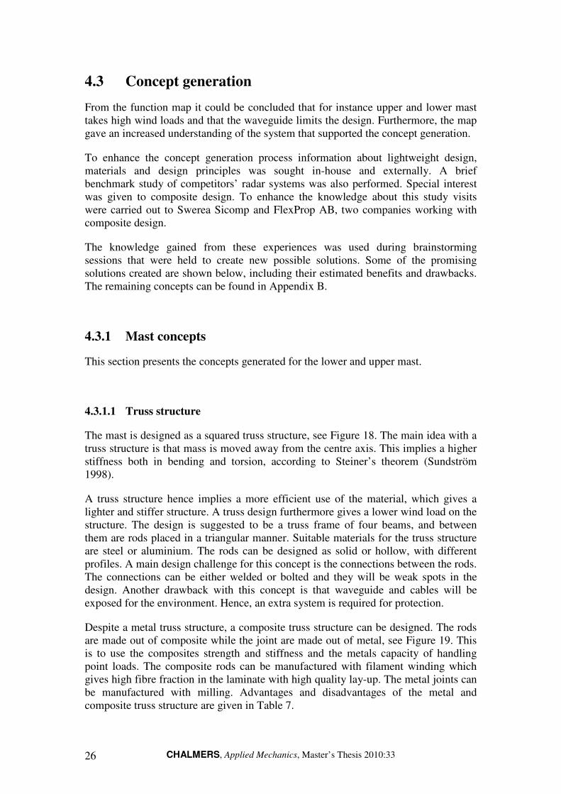
The mast is designed as a squared truss structure, see Figure 18. The main idea with a truss structure is that mass is moved away from the centre axis. This implies a higher stiffness both in bending and torsion, according to Steiner’s theorem (Sundström 1998).
A truss structure hence implies a more efficient use of the material, which gives a lighter and stiffer structure. A truss design furthermore gives a lower wind load on the structure. The design is suggested to be a truss frame of four beams, and between them are rods placed in a triangular manner. Suitable materials for the truss structure are steel or aluminium. The rods can be designed as solid or hollow, with different profiles. A main design challenge for this concept is the connections between the rods. The connections can be either welded or bolted and they will be weak spots in the design. Another drawback with this concept is that waveguide and cables will be exposed for the environment. Hence, an extra system is required for protection.
Despite a metal truss structure, a composite truss structure can be designed. The rods are made out of composite while the joint are made out of metal, see Figure 19. This is to use the composites strength and stiffness and the metals capacity of handling point loads. The composite rods can be manufactured with filament winding which gives high fibre fraction in the laminate with high quality lay-up. The metal joints can be manufactured with milling. Advantages and disadvantages of the metal and composite truss structure are given in Table 7.

CHALMERS, Applied Mechanics, Master’s Thesis 2010:33 27
Table 7 Advantages and disadvantages for a truss structure.
Advantages Disadvantages
Metal truss structure
Use of metals result in low material and manufacturing cost
Requires extra systems for shielding of cables and waveguide
Metal truss structure gives a light and stiff mast
May result in many welds, which are weak points in the design
Possible to re-use mast head and cylinder attachments
Many parts increase manufacturing time- and costs
Low projected area gives lower wind load
Composite truss structure
Composite truss structure gives a very light and stiff mast
Difficult to achieve appropriate tolerances in the joints between the composite rods
Figure 18 A) top view of one of the lower legs, B) side view of one of the lower
legs, C) top view of the upper mast and D) cross sections view.
Figure 19 Composite truss structure with composite rods and metal joints.
4.3.1.2 Material change
The current design of the mast is used, however the steel is replaced with a material that can result in weight reduction, either another metal or a composite. As concluded in the Section 3.1.2, aluminium can be a suitable material for the mast. The mast can then be designed in the same way as the current solution, using welded aluminium plates instead. However, it should be mentioned that even though aluminium is preferable for structures subjected to bending loads, its lightweight performance in pure tensile loads is lower than steel.

CHALMERS, Applied Mechanics, Master’s Thesis 2010:33 28
Composite materials like CFRP have very high potential for weight reduction, since the material has high lightweight performance. Manufacturing of lower or upper mast section as one part would require hand lay-up or vacuum moulding as manufacturing method. Both manufacturing methods require large moulds which will make manufacturing very expensive. It would furthermore require that the mould either is possible to split so that the separate pieces can be pulled out of the mast or that the mould is either inflatable or soluble. If it is discovered that this kind of mould becomes too complex, then the parts need to be split to be removed from the mould. The advantage of a one-piece design is that the number of joints can be reduced and therefore eliminate weak spots. The advantages and disadvantages are given in Table 8.
Table 8 Advantages and disadvantages for a material change concept.
Advantages Disadvantages
For metals
Reuse of design and components Small weight reduction potential
Low risk
For composites
Very high weight reduction potential High manufacturing cost with complex design and expensive tools
Possible to manufacture as one piece using vacuum moulding
4.3.1.3 Composite mast made from plates
The mast is designed using composite plates. Holes for inspection hatches can then be made prior to mounting the plates. By using this manufacturing method simple composite plates can be used, and no expensive moulds are needed.
The current design of the mast can be kept to large extent, however some modifications have to be done when introducing this design. The basic idea is to design the mast with plates that are joined together with adhesives, using profiles made out of metal or composite to increase the bonding area. Figure 20 shows a principal sketch of the solution. This concept will require modules that will work as the interface between the composite mast and the metal joint, see Section 4.3.3. The estimated advantages and disadvantages are given in Table 9.
Table 9 Advantages and disadvantages for the composite plate concept.
Advantages Disadvantages
High weight reduction potential Requires modules for the interfaces
Rather simple composite plates can be used

CHALMERS, Applied Mechanics, Master’s Thesis 2010:33 29
Figure 20 Different cross-sections of a mast leg made from composite plates with
glue profiles in the corner to join the plates.
4.3.1.4 Filament winded composite mast
The design of the mast is modified to make it possible to use filament winding as manufacturing method. A circular or elliptical cross-section is suitable, see Figure 21. A weight reduction is possible since a composite with high lightweight performance is used. A filament winded mast would require modules in the interfaces with the mast head and the joints, similar to the composite plate concept. The estimated advantages and disadvantages for a filament winded mast are given in Table 10.
Table 10 Advantages and disadvantages for a filament winded composite mast.
Advantages Disadvantages
High weight reduction potential Less optimized design from a stiffness perspective
Manufacturing with filament winding lowers the costs
Requires modules for the interfaces
Figure 21 A) top view of one of the lower legs, B) side view of one of the lower
legs and C) two possible cross sections, oval and circular.
4.3.2 Cylinder attachments
The high local forces around the cylinder attachments are currently dealt with utilizing an increased sheet metal thickness. For the concepts utilizing a truss structure or composite materials, new attachment solutions are necessary. This section presents the generated concepts for the cylinder attachments.
CHALMERS, Applied Mechanics, Master’s Thesis 2010:33 30
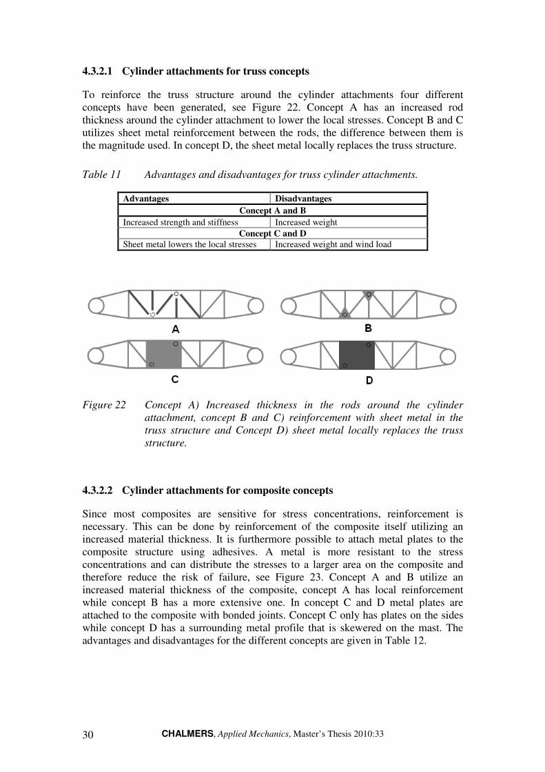
4.3.2.1 Cylinder attachments for truss concepts
To reinforce the truss structure around the cylinder attachments four different concepts have been generated, see Figure 22. Concept A has an increased rod thickness around the cylinder attachment to lower the local stresses. Concept B and C utilizes sheet metal reinforcement between the rods, the difference between them is the magnitude used. In concept D, the sheet metal locally replaces the truss structure.
Table 11 Advantages and disadvantages for truss cylinder attachments.
Advantages Disadvantages
Concept A and B
Increased strength and stiffness Increased weight
Concept C and D
Sheet metal lowers the local stresses Increased weight and wind load
Figure 22 Concept A) Increased thickness in the rods around the cylinder
attachment, concept B and C) reinforcement with sheet metal in the
truss structure and Concept D) sheet metal locally replaces the truss
structure.
4.3.2.2 Cylinder attachments for composite concepts
Since most composites are sensitive for stress concentrations, reinforcement is necessary. This can be done by reinforcement of the composite itself utilizing an increased material thickness. It is furthermore possible to attach metal plates to the composite structure using adhesives. A metal is more resistant to the stress concentrations and can distribute the stresses to a larger area on the composite and therefore reduce the risk of failure, see Figure 23. Concept A and B utilize an increased material thickness of the composite, concept A has local reinforcement while concept B has a more extensive one. In concept C and D metal plates are attached to the composite with bonded joints. Concept C only has plates on the sides while concept D has a surrounding metal profile that is skewered on the mast. The advantages and disadvantages for the different concepts are given in Table 12.
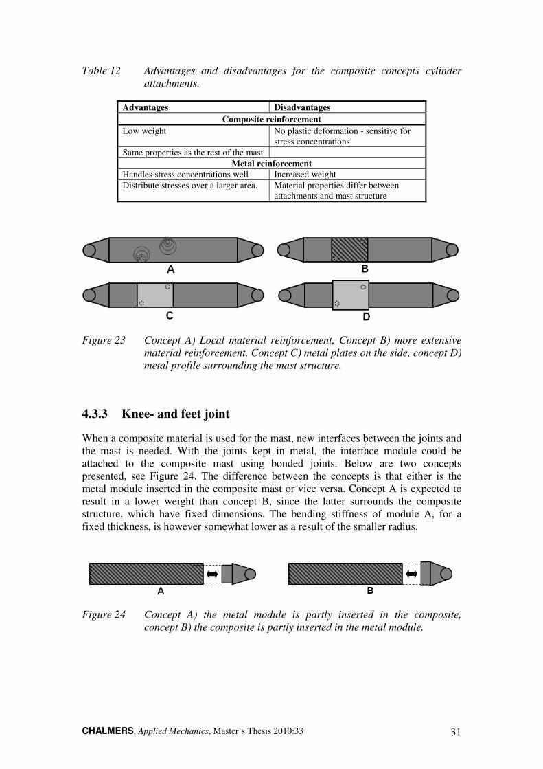
CHALMERS, Applied Mechanics, Master’s Thesis 2010:33 31
Table 12 Advantages and disadvantages for the composite concepts cylinder
attachments.
Advantages Disadvantages
Composite reinforcement
Low weight No plastic deformation - sensitive for stress concentrations
Same properties as the rest of the mast
Metal reinforcement
Handles stress concentrations well Increased weight
Distribute stresses over a larger area. Material properties differ between attachments and mast structure
Figure 23 Concept A) Local material reinforcement, Concept B) more extensive
material reinforcement, Concept C) metal plates on the side, concept D)
metal profile surrounding the mast structure.
4.3.3 Knee- and feet joint
When a composite material is used for the mast, new interfaces between the joints and the mast is needed. With the joints kept in metal, the interface module could be attached to the composite mast using bonded joints. Below are two concepts presented, see Figure 24. The difference between the concepts is that either is the metal module inserted in the composite mast or vice versa. Concept A is expected to result in a lower weight than concept B, since the latter surrounds the composite structure, which have fixed dimensions. The bending stiffness of module A, for a fixed thickness, is however somewhat lower as a result of the smaller radius.
Figure 24 Concept A) the metal module is partly inserted in the composite,
concept B) the composite is partly inserted in the metal module.
CHALMERS, Applied Mechanics, Master’s Thesis 2010:33 32
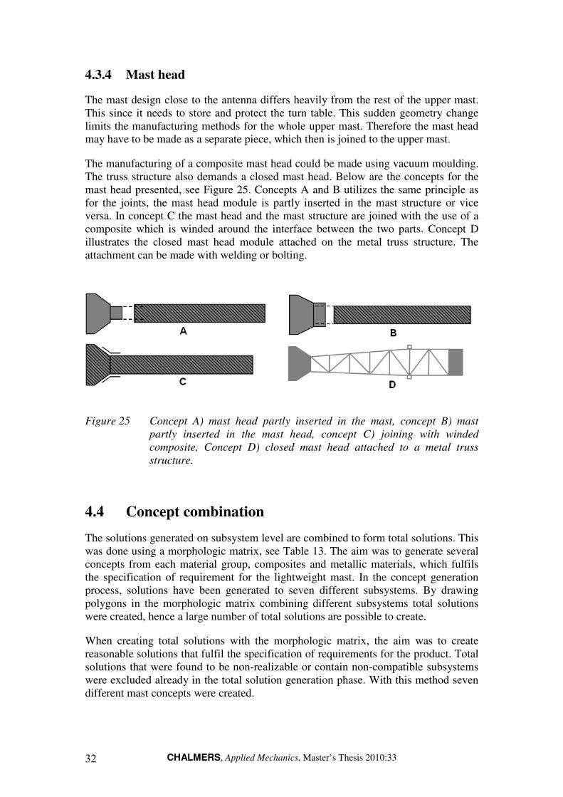
4.3.4 Mast head
The mast design close to the antenna differs heavily from the rest of the upper mast. This since it needs to store and protect the turn table. This sudden geometry change limits the manufacturing methods for the whole upper mast. Therefore the mast head may have to be made as a separate piece, which then is joined to the upper mast.
The manufacturing of a composite mast head could be made using vacuum moulding. The truss structure also demands a closed mast head. Below are the concepts for the mast head presented, see Figure 25. Concepts A and B utilizes the same principle as for the joints, the mast head module is partly inserted in the mast structure or vice versa. In concept C the mast head and the mast structure are joined with the use of a composite which is winded around the interface between the two parts. Concept D illustrates the closed mast head module attached on the metal truss structure. The attachment can be made with welding or bolting.
Figure 25 Concept A) mast head partly inserted in the mast, concept B) mast
partly inserted in the mast head, concept C) joining with winded
composite, Concept D) closed mast head attached to a metal truss
structure.
4.4 Concept combination
The solutions generated on subsystem level are combined to form total solutions. This was done using a morphologic matrix, see Table 13. The aim was to generate several concepts from each material group, composites and metallic materials, which fulfils the specification of requirement for the lightweight mast. In the concept generation process, solutions have been generated to seven different subsystems. By drawing polygons in the morphologic matrix combining different subsystems total solutions were created, hence a large number of total solutions are possible to create.
When creating total solutions with the morphologic matrix, the aim was to create reasonable solutions that fulfil the specification of requirements for the product. Total solutions that were found to be non-realizable or contain non-compatible subsystems were excluded already in the total solution generation phase. With this method seven different mast concepts were created.

CHALMERS, Applied Mechanics, Master’s Thesis 2010:33 33
Table 13 Total concept solutions resulting from combination of subsystems.
Sub-system Concept 1 – Material change metal
Concept 2 – Truss structure
Concept 3 – Material change composite
Concept 4 – Filament winded circular
Concept 5 – Filament winded oval
Concept 6 – Composite plates
Concept 7 – Hybrid truss structure
Lower mast Material change Metal
Truss structure Material change composite
Circular composite tube
Oval composite tube
Composite plates Composite and metal hybrid truss
Upper mast Material change Metal
Truss structure Material change composite
Circular composite tube
Oval composite tube
Composite plates Composite and metal hybrid truss
Cylinder attachment
Re-Use Increased rod thickness
Local composite reinforcement
Surrounding metal profile
Metal plates on the sides
Metal plates on the sides
Increased rod thickness
Knee joint Re-Use Truss welded to joint
Composite Metallic module – outside mast leg
Metallic module – outside mast leg
Metallic module – outside mast leg
Metallic with hole for composite rods
Mast feet joint Re-Use Truss welded to joint
Composite Metallic module – outside mast leg
Metallic module – outside mast leg
Metallic module – outside mast leg
Metallic with hole for composite rods
Mast head Metallic Metallic Composite Metallic with mast module
Metallic with mast module
Composite Metallic with holes for composite rods
Waveguide and cables
Inside mast – gives protection
Inside mast – limited protection
Inside mast – gives protection
Inside mast – gives protection
Inside mast – gives protection
Inside mast – gives protection
Inside mast – limited protection
CHALMERS, Applied Mechanics, Master’s Thesis 2010:33 34
4.5 Concept evaluation
The solutions created were evaluated in order to find the concept from each material group that best fulfils the specification of requirements. This evaluation was performed using engineering selection methods (Johannesson 2004). The first step was to perform a concept screening where the concepts are ranked using Pugh’s relative matrix. When the concepts were evaluated with relative methods, a concept
scoring was performed. Here the highest ranked concepts from the concept screening were evaluated with weighted criterions using a Kesselring matrix. Based on this result two final concepts were selected.
4.5.1 Evaluation criterions
Evaluation of concepts with Pugh- and Kesselring matrices are performed with selected criterions from the specifications of requirements. Focus should be on the desired properties but also strict requirements can be included. The evaluation criterions are shown in Table 14 below. A description of each criterion can be found in Appendix A.
Table 14 Evaluation criterions used for concept screening- and scoring.
Requirement/Desired property Req/Dp Importance
1.3 High weight reduction Dp 5
1.4 Low projected area Dp 4
1.5 Low complexity Dp 3
4.2 High natural frequency Dp 3
4.4 Large strength margin Dp 4
5.2 High toughness Dp 3
6.3 Low cost Dp 3
4.5.2 Concept screening
The screening of concepts is based on Pugh’s relative matrix. The Pugh method compares the solutions and ranks them relative each other. A reference solution is chosen, and the solutions are then compared with the reference for each of the criterions specified in Section 4.5.1. After the evaluation is completed the highest ranked solution is chosen as a reference, in this way the evaluation process is iterated. Note that the Pugh matrix takes no consideration to the relative importance of criterions. It can also be difficult to estimate the performance of a solution on concept level (Johannesson 2004). The Pugh matrix can be found in Appendix C. After the concept screening there are six concepts remaining for further evaluation. Five of these concepts utilize composite material and one uses metallic material. Since the steel truss structure is the only metallic concept remaining, and the aim is to find one concept from each material group, the steel truss structure can be chosen as the final metallic concept.

CHALMERS, Applied Mechanics, Master’s Thesis 2010:33 35
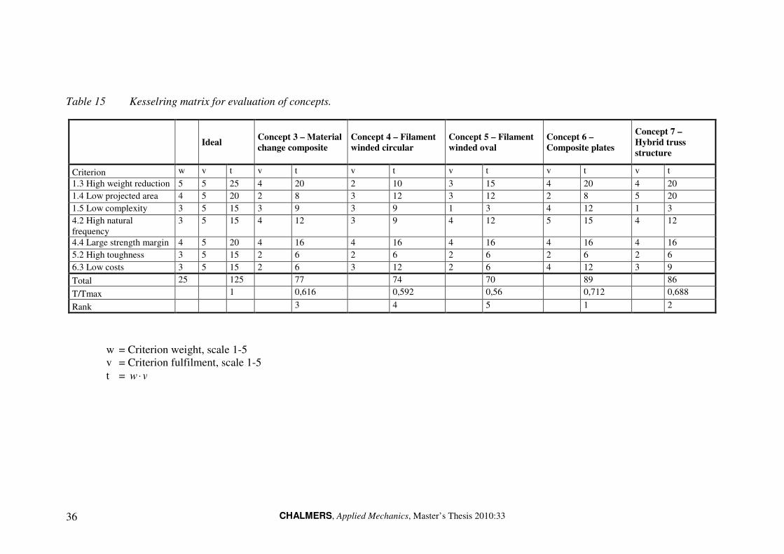
4.5.3 Concept scoring
In this final concept scoring the solutions were evaluated quantitatively, using a Kesselring matrix with weighted criterions. This methodology was used to evaluate and select one of the five remaining composite concepts. The criterions used were the same as in the concept screening. In the Kesselring matrix each concept was evaluated based on the performance of each selected criterion, where the scale 1-5 was used. The value was then multiplied with the importance of each criterion. All the values were then summarized, which gave an overall estimation of the performance of a concept. Based on this value the concepts were ranked, see Table 15.
CHALMERS, Applied Mechanics, Master’s Thesis 2010:33 36
Table 15 Kesselring matrix for evaluation of concepts.
Ideal Concept 3 – Material change composite
Concept 4 – Filament winded circular
Concept 5 – Filament winded oval
Concept 6 – Composite plates
Concept 7 – Hybrid truss structure
Criterion w v t v t v t v t v t v t
1.3 High weight reduction 5 5 25 4 20 2 10 3 15 4 20 4 20
1.4 Low projected area 4 5 20 2 8 3 12 3 12 2 8 5 20
1.5 Low complexity 3 5 15 3 9 3 9 1 3 4 12 1 3
4.2 High natural frequency
3 5 15 4 12 3 9 4 12 5 15 4 12
4.4 Large strength margin 4 5 20 4 16 4 16 4 16 4 16 4 16
5.2 High toughness 3 5 15 2 6 2 6 2 6 2 6 2 6
6.3 Low costs 3 5 15 2 6 3 12 2 6 4 12 3 9
Total 25 125 77 74 70 89 86
T/Tmax 1 0,616 0,592 0,56 0,712 0,688
Rank 3 4 5 1 2
w = Criterion weight, scale 1-5 v = Criterion fulfilment, scale 1-5
t = vw ⋅

CHALMERS, Applied Mechanics, Master’s Thesis 2010:33 37
4.5.4 Concept selection
After the concept screening, there are only one metallic concept remaining, which is selected for further development. This is a metallic truss structure with subsystems configuration according to Figure 26.
Figure 26 The subsystems for the metallic truss structure concept.
In the Kesselring matrix the concept with the highest score is concept six, which is a solution using composite plates. This concept was therefore chosen for further development. The subsystem solutions for the concept can be seen in Figure 27.
Figure 27 The subsystem for the composite mast made from plates.
4.6 Detailed design
In the concept development process two solutions have been chosen, one metallic and one composite. These solutions were further developed. The aim with the detailed design is to create solutions that are possible to analyze and verify according to the specifications of requirements.
In the design process the 3D CAD system Pro/Engineer was used. It was important to assure geometric compatibility with other systems like shelter, mast feet, turn table and hydraulic cylinders. To ensure compatibility the CAD-models for the concepts were based on a CAD-skeleton model from the current mast. The skeleton model contains datum entities which can be used as references in the model development. Some subsystems from the current mast are also used and modified to fit the new design.

CHALMERS, Applied Mechanics, Master’s Thesis 2010:33 38
4.6.1 Truss mast
In this section the detailed design of the truss mast is described. The design of the truss mast is shown in Figure 28 below. Subsystems like mast feet and locking devices were not modeled. The influence on stiffness of the mast feet was omitted in an initial analysis of the structural performance of the mast.
Figure 28 CAD-model of the truss mast.
4.6.1.1 Truss structure design
The lower and upper masts were designed as truss structures with four square frame beams with rods welded in-between in a triangular manner, see Figure 29. The upper and lower mast sections can be seen as beams loaded in bending and compression by the wind load and weight of the antenna unit, respectively. By using a truss structure mass is moved away from the centre axis, thus giving a stiffer structure. An analogy is an I-beam, where the truss frame can be seen as the flange and the truss rods as the web. The truss structure was made fully parametric so that dimensions of the truss frame and the rods easily can be changed. In this way the results from the optimization with FE-tools can be used to update the model with final dimensions. Twice the amount of rods was used on the sides compared to the upper and lower part of each mast section, see Figure 29.

CHALMERS, Applied Mechanics, Master’s Thesis 2010:33 39
Design of the joints between the beams and the rods in the truss structure have to be considered. The welded joints give local flexibilities, which reduces the stiffness of the mast. However for an initial analysis of the structural performance detailed design of the joints was omitted.
Figure 29 Design of truss structure in the mast.
4.6.1.2 Lower mast
The lower mast consists of two mast legs each consisting of a cross-section of four truss frame beams with rods in-between, see Figure 30. The truss frame is attached by welds to the mast feet joints, cylinder attachments and knee joint. In total eight truss frame beams are needed for one mast leg. In order to have high stiffness the cross-section of the mast leg is kept as wide as possible. Stiffeners are placed between the two mast legs to increase the masts torsional stiffness.
Figure 30 Lower mast with stiffeners.
CHALMERS, Applied Mechanics, Master’s Thesis 2010:33 40
4.6.1.3 Upper mast
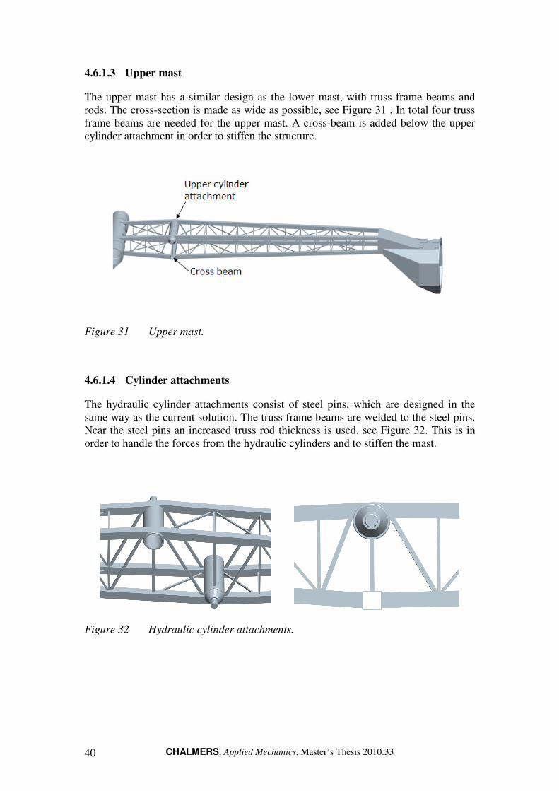
The upper mast has a similar design as the lower mast, with truss frame beams and rods. The cross-section is made as wide as possible, see Figure 31 . In total four truss frame beams are needed for the upper mast. A cross-beam is added below the upper cylinder attachment in order to stiffen the structure.
Figure 31 Upper mast.
4.6.1.4 Cylinder attachments
The hydraulic cylinder attachments consist of steel pins, which are designed in the same way as the current solution. The truss frame beams are welded to the steel pins. Near the steel pins an increased truss rod thickness is used, see Figure 32. This is in order to handle the forces from the hydraulic cylinders and to stiffen the mast.
Figure 32 Hydraulic cylinder attachments.

CHALMERS, Applied Mechanics, Master’s Thesis 2010:33 41
4.6.1.5 Mast head
The mast head is designed using a closed metallic interface. The solution is based on the current mast head, with a small modification to make it possible to join with the truss frame. For the joint a steel plate is used, which is welded to the truss frame beams and to the mast head, see Figure 33.
Figure 33 Steel mast head.
4.6.2 Composite mast
The detailed design of the mast made from composite plates is described in this section. This concept is from now on denoted the composite mast and can be seen in Figure 34. The mast is build up by composite plates that are joined together with glue profiles. Since the feet- and knee joints are made in metal, interface modules to them from upper and lower mast are necessary. The mast head’s complex design makes it necessary to manufacture as one coherent piece, using vacuum bag moulding. The carbon fibre reinforced epoxy laminates can be manufactured with a varying thickness and fibre direction. This, since the number and direction of the plies that make up the laminate can be varied depending on what is desired. The design utilizes a hollow cross-section in lower and upper mast with as few plates as possible to minimize the number of joints.
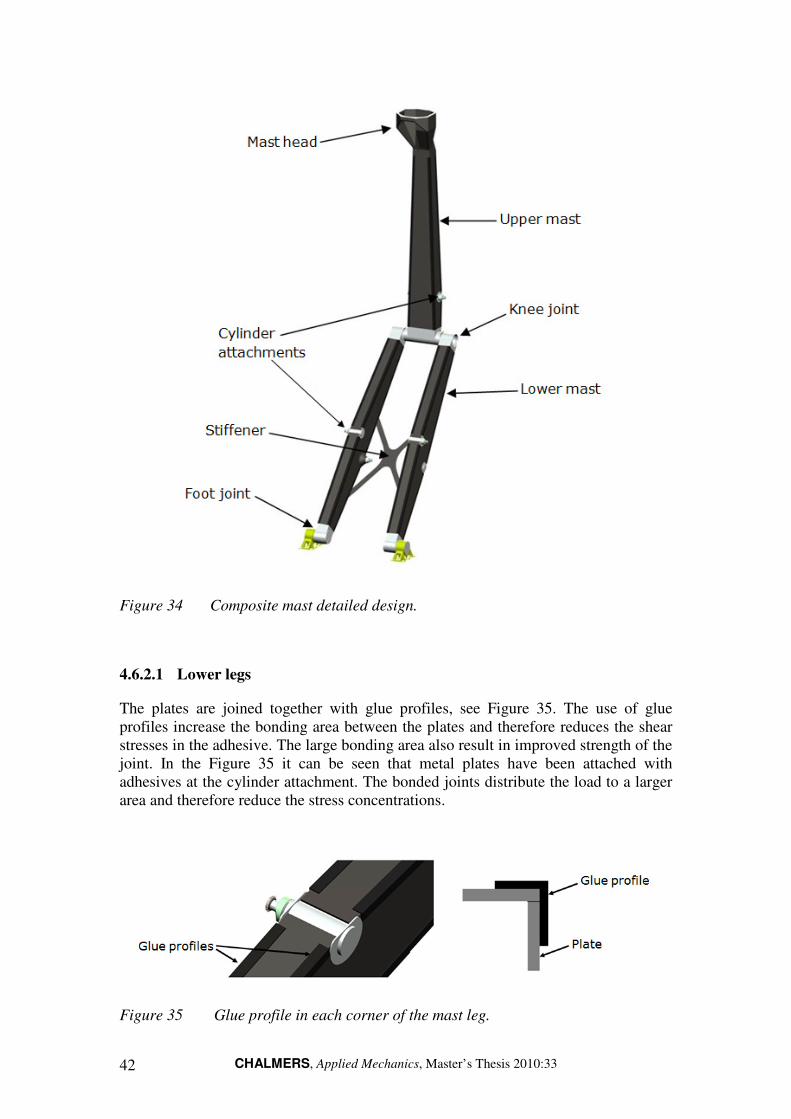
CHALMERS, Applied Mechanics, Master’s Thesis 2010:33 42
Figure 34 Composite mast detailed design.
4.6.2.1 Lower legs
The plates are joined together with glue profiles, see Figure 35. The use of glue profiles increase the bonding area between the plates and therefore reduces the shear stresses in the adhesive. The large bonding area also result in improved strength of the joint. In the Figure 35 it can be seen that metal plates have been attached with adhesives at the cylinder attachment. The bonded joints distribute the load to a larger area and therefore reduce the stress concentrations.
Figure 35 Glue profile in each corner of the mast leg.

CHALMERS, Applied Mechanics, Master’s Thesis 2010:33 43
The reduction of plates was accomplished with a design that has continuous surfaces on the sides of the mast, see Figure 36.
Figure 36 The current mast to the left and the composite mast to the right.
However, the design resulted in a slimmer width at the cylinder attachments, see Figure 36. Hence, an increased distance from the hydraulic cylinder attachment point to the surface of the mast. A cone was therefore designed to increase the stiffness at the attachments, see Figure 37.
Figure 37 The left picture shows the cylinder attachment stiffeners from the front
of the leg and the right picture shows them from the back.
4.6.2.2 Upper mast
The number of plates has been reduced in the same way as for the lower mast. One of the design changes that made this possible can be seen in Figure 38. One plate is used on the bottom side. A plate joint on the top side is unavoidable as a result of the cylinder attachment position. Similar to the lower mast is a metal plate attached with adhesives at the cylinder attachment to distribute the load to a larger area.

CHALMERS, Applied Mechanics, Master’s Thesis 2010:33 44
Figure 38 The left picture shows the current solution and the right picture shows
the composite mast. Note that only one plate is used on the bottom side
of the composite mast.
4.6.2.3 Mast head
The lack of knowledge of how the turntable affects the mast head design hindered a redesign of it. Factors that influence the design is space for mounting of turntable and space for proper cooling of the electrical components. The current design was therefore principally translated to fit a composite. The partly closed design also demands that either the mast head is done as two separate pieces or that the mould is possible to split so that it can be pulled out from the mast head, see Figure 39.
Figure 39 The composite mast head.
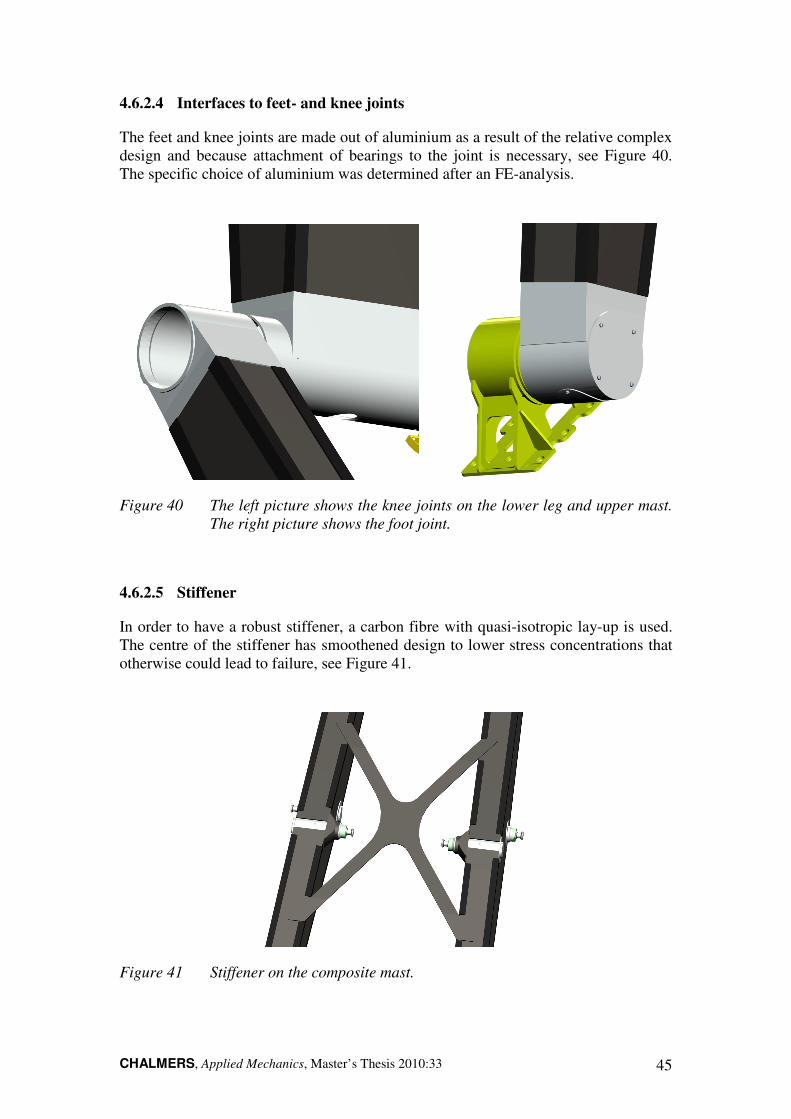
CHALMERS, Applied Mechanics, Master’s Thesis 2010:33 45
4.6.2.4 Interfaces to feet- and knee joints
The feet and knee joints are made out of aluminium as a result of the relative complex design and because attachment of bearings to the joint is necessary, see Figure 40. The specific choice of aluminium was determined after an FE-analysis.
Figure 40 The left picture shows the knee joints on the lower leg and upper mast.
The right picture shows the foot joint.
4.6.2.5 Stiffener
In order to have a robust stiffener, a carbon fibre with quasi-isotropic lay-up is used. The centre of the stiffener has smoothened design to lower stress concentrations that otherwise could lead to failure, see Figure 41.
Figure 41 Stiffener on the composite mast.

CHALMERS, Applied Mechanics, Master’s Thesis 2010:33 46
4.6.2.6 Selected composite material
In order to find a suitable composite material for this concept, the market was analyzed for a material that fulfils the requirements. The final material selection is the SE 84LV epoxy prepreg system from SP Gurit High Modulus. It is versatile, high-strength prepreg system. Furthermore, is has excellent tack and low viscosity, which makes it ideal for use with heavy fibres. SE 84LV has a Tg ≈130ºC, which is sufficient to satisfy the upper service temperature. The lower limit of service temperature was not listed but is in general not an issue, see Table 6 in Section 3.3.2.1. The matrix is commonly used for vacuum bag moulding and therefore suits this design. The high toughness property of the prepreg system improves the impact strength. The material UV-resistance is acceptable and can be further improved with the use of carbon black. However, since the mast will be painted the matrix will not experience any direct UV-radiation. Material data also indicates that the epoxy has the desired chemical resistance. The SE 84 LV epoxy prepreg system can be used with different types of carbon fibres. A compilation of the mechanical properties and prices with different reinforcing fibres are given in Table 16.
Table 16 Material properties for SE 84LV epoxy prepreg system with high
strength (HS300), intermediate modulus (IM300) and high modulus
carbon fibres (HM300).
Material data HS300 IM300 HM300
Volume fraction fibre [%] 60 60 60
Longitudinal elastic modulus [MPa] 139 600 174 300 223 100
Transverse elastic modulus [MPa] 7700 7200 6800
Interlaminar shear modulus [MPa] 4500 4600 4600
In-plane shear modulus [MPa] 4500 4600 4600
Poisson’s ratio 0.337 0.337 0.337
Density [kg/m3] 1560 1560 1560
Price [kr/kg]2 341 739 1044
2 The cost was originally given in £/kg, converted with the current valid for the date 2010-06-04 (11.56 kr/£).

CHALMERS, Applied Mechanics, Master’s Thesis 2010:33 47
5 FE-models and analysis
The two mast concepts were analyzed using FE-methods. The developed CAD-models were imported to the FE-preprocessor Patran and used as a base for the FE-models. A drawback with this work methodology is that modifications have to be carried out in both the FE-models and CAD-models.
The analysis and optimization on the FE-models were performed with the FE-code Nastran. Using optimization it is possible to minimize the mass and obtain the desired natural frequencies. However, after the optimization it is crucial to analyze the mast with respect to strength and buckling for the loads that the mast is subjected to, see Section 2.3.
This chapter starts by giving an introduction to the composite mechanics used in the analysis. The finite element method, natural frequencies and buckling are also briefly described. Then the FE-model development, optimization, strength and buckling analysis are described.
5.1 Composite mechanics
5.1.1 Anisotropy
Composite materials are anisotropic, which means that the properties vary in different directions of the material. This is in opposite to most metallic materials, which are considered isotropic and have the same elastic properties in all directions. A composite which have all the fibres oriented in one direction is called a unidirectional composite. For a unidirectional composite, having the fibres in one direction implies that the material is essentially isotropic in a plane perpendicular to the fibre. The mechanical properties are very different in the fibre direction compared to the other two directions. The elastic properties are symmetric with respect to the (1-2-3) axes, see Figure 42. Such a material is called orthotropic, and the (1-2-3) axes in Figure 42 are called the principal axes (Matthews 2000). For an orthotropic material there exist nine independent elastic constants.
Figure 42 Principal material axes.
CHALMERS, Applied Mechanics, Master’s Thesis 2010:33 48
5.1.2 Stress-strain relation for unidirectional composites
Unidirectional composites are a special class of orthotropic materials. Since the elastic properties are equal in the 2-3 direction, the number of elastic constants reduces from nine to five (Mallick 2008). However, only four of these constants are independent. Such a material is called transversely isotropic. Consider the material shown in Figure 42, if stresses are applied in the direction of the principal axes, the strains in terms of the stresses are (Matthews 2000):
[ ]
[ ]T
T
S
122112
122112
1212
τσσσ
γεεε
σε
=
=
=
(2)
And the compliance matrix S is defined as:
−
−
=
12
2211
12
22
12
11
100
01
01
G
EE
EE
Sυ
υ
(3)
Where:
E11 is the elastic modulus in the longitudinal direction. E22 is the elastic modulus in the transverse direction. G12 is the shear modulus in the 1-2 axes. ν12 is the major Poisson’s ratio. ν21 is the minor Poisson’s ratio.
It is also possible to write the stresses as functions of the strains, Equation 2 becomes (Matthews 2000):
1
1212
−=
=
SQ
Qεσ (4)
Where Q is the ply stiffness matrix.
5.1.3 Off-axis loading on unidirectional composites
A composite laminate consists of plies of unidirectional fibres stacked on top of each other. The fibre direction usually changes from layer to layer. For some layers the fibres are not aligned with the applied stress. These layers are subjected to off-axis
loading (Matthews 2000). A unidirectional lamina subjected to off-axis loading is shown in Figure 43.
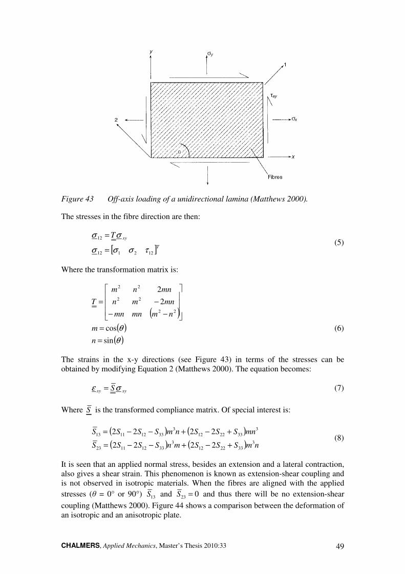
CHALMERS, Applied Mechanics, Master’s Thesis 2010:33 49
Figure 43 Off-axis loading of a unidirectional lamina (Matthews 2000).
The stresses in the fibre direction are then:
[ ]T
xyT
122112
12
τσσσ
σσ
=
= (5)
Where the transformation matrix is:
( )( )
( )θ
θ
sin
cos
2
2
22
22
22
=
=
−−
−=
n
m
nmmnmn
mnmn
mnnm
T
(6)
The strains in the x-y directions (see Figure 43) in terms of the stresses can be obtained by modifying Equation 2 (Matthews 2000). The equation becomes:
xyxy Sσε = (7)
Where S is the transformed compliance matrix. Of special interest is:
( ) ( )
( ) ( ) nmSSSmnSSSS
mnSSSnmSSSS
3
332212
3
33121123
3
332212
3
33121113
2222
2222
+−+−−=
+−+−−= (8)
It is seen that an applied normal stress, besides an extension and a lateral contraction, also gives a shear strain. This phenomenon is known as extension-shear coupling and is not observed in isotropic materials. When the fibres are aligned with the applied
stresses (θ = 0° or 90°) 13S and 023 =S and thus there will be no extension-shear
coupling (Matthews 2000). Figure 44 shows a comparison between the deformation of an isotropic and an anisotropic plate.
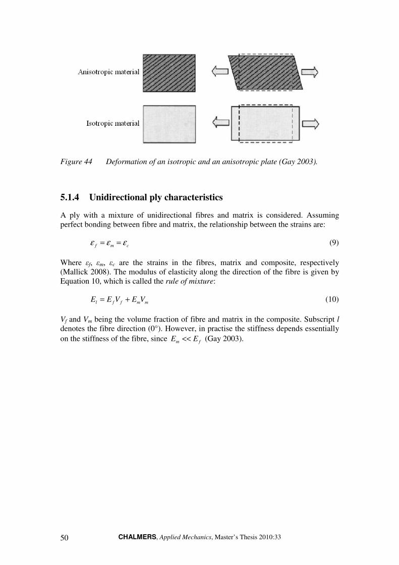
CHALMERS, Applied Mechanics, Master’s Thesis 2010:33 50
Figure 44 Deformation of an isotropic and an anisotropic plate (Gay 2003).
5.1.4 Unidirectional ply characteristics
A ply with a mixture of unidirectional fibres and matrix is considered. Assuming perfect bonding between fibre and matrix, the relationship between the strains are:
cmf εεε == (9)
Where εf, εm, εc are the strains in the fibres, matrix and composite, respectively (Mallick 2008). The modulus of elasticity along the direction of the fibre is given by Equation 10, which is called the rule of mixture:
mmffl VEVEE += (10)
Vf and Vm being the volume fraction of fibre and matrix in the composite. Subscript l denotes the fibre direction (0°). However, in practise the stiffness depends essentially
on the stiffness of the fibre, since fm EE << (Gay 2003).

CHALMERS, Applied Mechanics, Master’s Thesis 2010:33 51
5.1.5 Mechanical behaviour of laminated structures
5.1.5.1 Laminates
A laminate is designed by stacking a number of plies on top of each other. Some common types of laminates are describes below (Mallick 2008).
• Unidirectional laminate: Fibre orientation is the same in all laminates.
• Cross-ply laminate: Fibre orientation alternates as 0°/90°/0°/90°.
• Angle-ply laminate: Fibre orientation alternates between the layers as θ/-θ/θ/-θ, where θ ≠ (0° or 90°).
• Symmetric laminate: The ply orientation is symmetric with respect to the midplane of the laminate, so that θ(z) = θ(-z). A four ply laminate stacked in the sequence 0°/90°/90°/0° is usually denoted (0°/90°)s, where the subscript s
means that the stacking is symmetric.
• Antisymmetric laminates: The ply orientation is antisymmetric with respect to the midplane of the laminate. Hence for each ply oriented at an angle θ above the midplane, there is a ply oriented -θ below the midplane (θ(z) = -θ(-z)).
• Unsymmetric laminates: There is no symmetry or antisymmetry for these laminates.
Figure 45 shows the principal stacking of the plies for some of the laminates mentioned above.
Figure 45 From left to right: Unidirectional-, angle ply- and cross ply laminate
(Mallick 2008).
5.1.5.2 Lamination theory
Lamination theory is used to calculate the stresses and strains in each lamina of a thin laminated structure. A sketch of a laminate is shown in Figure 46. The total thickness is h and the number of laminas is N.

CHALMERS, Applied Mechanics, Master’s Thesis 2010:33 52
Figure 46 Geometry of a laminate.
A laminate may be subjected to both in-plane and transverse loading. The total strain is dependent of the in-plane strain, which is constant through the thickness, and the bending strains, which varies linearly with the distance from the mid-plane. An expression for the total strain in a lamina is:
xyxyxy
yyyyyy
xxxxxx
z
z
z
κγγ
κεε
κεε
+=
+=
+=
°
°
°
(11)
Where:
°xxε = Midplane normal strain in the x-direction. °yyε = Midplane normal strain in the y-direction.
°xyγ = Midplane shear strain.
xxκ = Bending curvature in the x-direction.
yyκ = Bending curvature in the y-direction.
xyκ = Twisting curvature.
z = Distance from midplane of the laminate.
Or in matrix form:
κεε z+=°
(12)
The stress in lamina j can be calculated by using its stiffness matrix, according to Equation 13:

CHALMERS, Applied Mechanics, Master’s Thesis 2010:33 53
=
°
°
°
xy
yy
xx
j
j
yy
xx
Q
γ
ε
ε
τ
σ
σ
(13)
Outer forces and moments acting on a laminate can be related to the mid-plane strains and curvature with Equation 14. Equation 14 is known as the plate constitutive
equation and the associated analysis as Classical Laminate Theory (Matthews 2000).
κε
κε
DBM
BAN
+=
+=
°
°
(14)
A , B , and D are all 3x3 matrices, denoted as (Mallick 2008):
A = Extensional stiffness matrix.
B = Coupling stiffness matrix.
D = Bending stiffness matrix.
The elements of the stiffness matrices are functions of the elastic properties of each
lamina and its location with respect to the midplane of the laminate. The B matrix
represent extension-bending coupling. If B is a nonzero matrix, an applied normal
force will create extension and shear deformation, as well as bending-twisting curvatures. Similarly an applied moment will create bending and twisting curvatures as well as extension-shear deformation (Mallick 2008). Such extension-bending
coupling is unique for laminated structures. Some terms in the A matrix represent
normal stress-shear strain coupling, as described earlier in Section 5.1.3. The D
matrix also contains some terms that represent bending moment-twisting curvature coupling.
Couplings like this can sometimes be an undesirable property of the laminate. If the laminate is stacked properly, some of the couplings can be eliminated. For a
symmetric laminate, 0=B and there is no extension-bending coupling. A laminate
that for any lamina with θ location, has an identical laminate at -θ location, will give no normal stress-shear strain coupling. This is called a balanced laminate. The location of the laminas is arbitrary. If the laminas are located at the same distance from the midplane, the bending moment-twisting curvature coupling will be eliminated.
5.1.5.3 Failure of laminates
A property that is different for composites compared with metallic materials is that composite materials do not deform plastically, therefore there is no such property as yield strength for a composite material. Usually the fibre failure strain is lower than the matrix failure strain. Failure of a ply in a composite laminate occurs when the stress/strain in the ply exceeds some critical value. There exist a variety of theories

CHALMERS, Applied Mechanics, Master’s Thesis 2010:33 54
used to predict failure of composite materials. Criterion for failure prediction is mainly of three types (Vinson 2002):
• Stress dominated criterions.
• Strain dominated criterions.
• Interactive criterions (Hill-Tsai, Hoffman theory).
In this work, the maximum strain theory has been used, which also is employed at Saab. According to the maximum strain theory, failure of the ply occurs when the strains along the material principal axis exceed their limiting values, according to Equation 15:
t
t
t
t
EE
G
EE
EE
,33
33
2232
33
113133
,12
12
1212
,22
22
1112
22
2222
,11
11
2212
11
1111
εσ
νσ
νε
γσ
γ
εσ
νσ
ε
εσ
νσ
ε
=−−=
==
=−=
=−=
(15)
The maximum strain theory is used to determine failure of laminates. The strains in each ply are determined according to Equation 12 and Equation 14. If the strains do not coincide with the principal material direction, they should be transformed using the transformation matrix (Equation 6). When the strains in each ply have been determined, the maximum strain criterion is used to predict failure of that ply. First ply failure is an analysis often made for laminated structures.

CHALMERS, Applied Mechanics, Master’s Thesis 2010:33 55
5.2 The finite element method
This section intends to give a basic overview of the finite element method. The theoretical foundation of the methods is first briefly described. The finite elements used in the models are explained, as well as the methods application to composite materials.
5.2.1 Theory
The finite element method is a numerical method used for finding approximate solutions to partial differential equations. Consider an arbitrary 3D solid with volume V and surface S (local normal ‘n’), subjected to surface forces ps per unit area and volume body forces pv per unit volume, see Figure 47.
Figure 47 Arbitrary 3D solid subjected to surface and volume forces.
The differential equation of equilibrium for the body can be written as:
0~
=+∇v
T pσ (16)
Where:
T∇~
= 3x6 differential operator matrix.
σ = Stress vector.
vp = Body forces per unit volume.
The body is furthermore subjected to surface forces s
p , per unit volume. The surface
forces must fulfil the equilibrium boundary condition:
zzzyzyxzxzs
zyzyyyxyxys
zxzyxyxxxxs
nnnp
nnnp
nnnp
σσσ
σσσ
σσσ
++=
++=
++=
,
,
,
(17)

CHALMERS, Applied Mechanics, Master’s Thesis 2010:33 56
Equation 16 can be multiplied by an arbitrary vector [ ]zyx vvvv = , integrated over
the volume V with use of the Green-Gauss theorem (Ottosen 1992). This gives Equation 16 in weak form:
( ) ∫∫∫ +=∇V
T
Ss
T
V
T
dVbvdSpvv σ~
(18)
This way of rewriting Equation 16 is analogous to the principle of virtual work.
5.2.1.1 Finite elements approximation
The next step is to divide the area of interest into finite elements which is used to approximate the displaced shape. This procedure is called meshing. The
displacements [ ]wvuu = are approximated as a linear combination of the nodal
displacements:
aNu = (19)
Where N is the global shape function matrix. Different shape functions are used
depending on element type. According to Galerkin’s method, the arbitrary vector v is
chosen as (Ottosen 1992):
cNv = (20)
Where also the vector c is arbitrary. Some definitions are now to introduce the
constitutive matrix D , the kinematic relationship u∇=~
ε and the matrix NB ∇=~
.
Furthermore boundary conditions are introduced to the solution. Boundary condition
can be natural boundary condition – prescribed surface forces s
p , or essential
boundary conditions – prescribed displacement vector u . The integration around the
boundary S is divided into hS with known surface forces and gS with known
displacements. Equation 18 now takes the form:
dVbNdSpNdSpNadVBDBV
T
Ss
T
Shs
T
V
T
gh
∫∫∫∫ ++=
,
(21)
For one element, the element stiffness matrix e
K and element load vectore
f is
defined as:
dVbNdSpNdSpNf
dVBDBK
V
Te
Ss
Te
Shs
Tee
e
V
Tee
egeh
e
∫∫∫
∫
++=
=
,,
,
,
,
,,
(22)

CHALMERS, Applied Mechanics, Master’s Thesis 2010:33 57
Hence giving the FE-equation for one element, eee
faK = . Finally the element
stiffness matrices and load vectors are assembled to a global structural stiffness
matrix K and a global load vector f :
∑∑
=
=
e
e
ff
KK (23)
This gives the global FE-equation system:
faK = (24)
The essential boundary conditions enter the equation system in the nodal displacement
vector a . Solving Equation 24 gives the nodal displacement and the reaction forces
where the displacements are prescribed. The equation system is usually solved using iterative methods.
5.2.1.2 Finite element types
There exist several types of finite elements. In this work, beam and shell elements have been used. The kinematic assumption for engineering beams is called Euler-
Bernoulli theory, which is that plane sections normal to the beam axis remain plane and normal to the beam axis during deformation. Mathematically, the beam bending differential equation is written:
)(2
2
2
2
xqdx
wdEI
dx
d=
(25)
Beam elements are derived from Equation 25. The beam elements used have six degrees of freedom in each node, it is shown in Figure 48. A cubic displacement shape function is assumed for the deflection. The essential boundary conditions are the deflection w and the curvature dw/dx. Natural boundary conditions are the shear forces V and moments M. The beam element then fulfils the requirement of completeness and compatibility (Ottosen 1992). A beam element is accurate since a cubic shape function is a high-order approximation.
The shell elements used in the models are 2D isoparametric four-node quadrilateral elements. The shell element has five degrees of freedom in each node, as seen in Figure 48. A kinematic assumption that includes bending and membrane behaviour has been used. The effect of transverse shear is also included, using Mindlin plate
theory (Schaeffer 1984). The shape functions used for a four-node shell element are:
ξηαηαξααηξ 4321),( +++=u (26)
The ξη -term in Equation 26 is called a parasitic term (Ottosen 1992). Convergence
rate will not be higher than for the linear element, since the polynomial only is complete up to the first grade. However the parasitic term will increase the accuracy
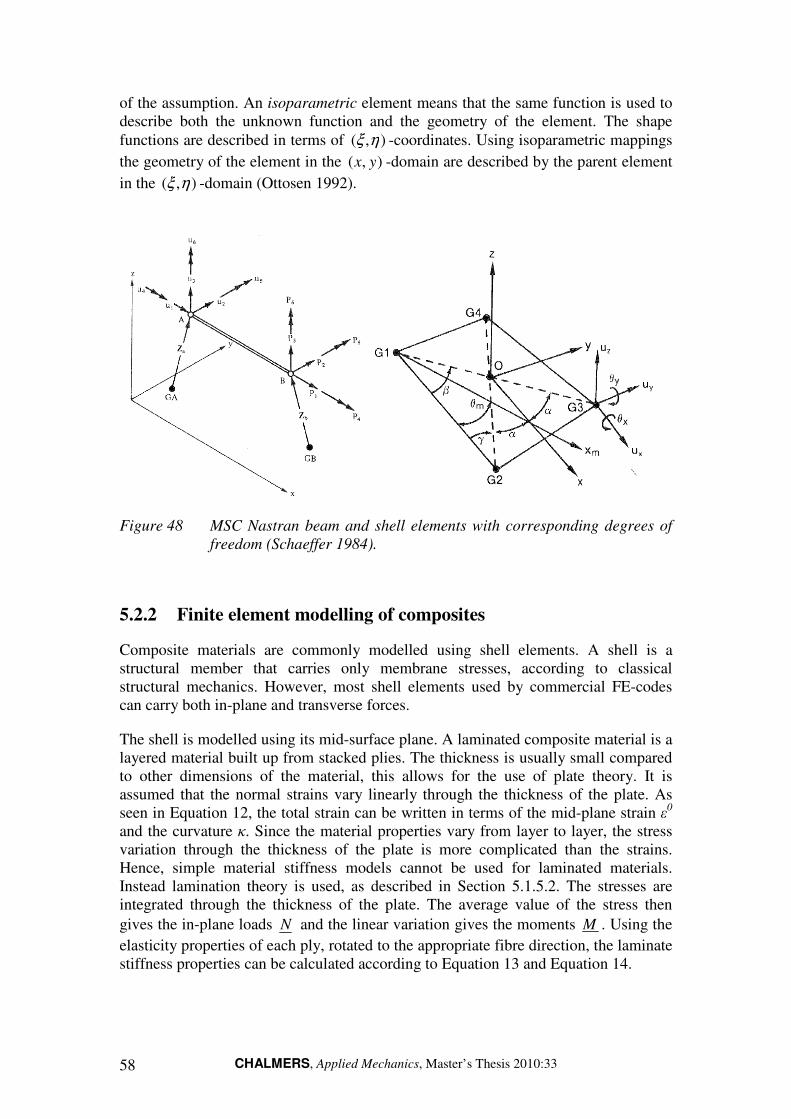
CHALMERS, Applied Mechanics, Master’s Thesis 2010:33 58
of the assumption. An isoparametric element means that the same function is used to describe both the unknown function and the geometry of the element. The shape
functions are described in terms of ),( ηξ -coordinates. Using isoparametric mappings
the geometry of the element in the ),( yx -domain are described by the parent element
in the ),( ηξ -domain (Ottosen 1992).
Figure 48 MSC Nastran beam and shell elements with corresponding degrees of
freedom (Schaeffer 1984).
5.2.2 Finite element modelling of composites
Composite materials are commonly modelled using shell elements. A shell is a structural member that carries only membrane stresses, according to classical structural mechanics. However, most shell elements used by commercial FE-codes can carry both in-plane and transverse forces.
The shell is modelled using its mid-surface plane. A laminated composite material is a layered material built up from stacked plies. The thickness is usually small compared to other dimensions of the material, this allows for the use of plate theory. It is assumed that the normal strains vary linearly through the thickness of the plate. As seen in Equation 12, the total strain can be written in terms of the mid-plane strain ε0 and the curvature κ. Since the material properties vary from layer to layer, the stress variation through the thickness of the plate is more complicated than the strains. Hence, simple material stiffness models cannot be used for laminated materials. Instead lamination theory is used, as described in Section 5.1.5.2. The stresses are integrated through the thickness of the plate. The average value of the stress then
gives the in-plane loads N and the linear variation gives the moments M . Using the
elasticity properties of each ply, rotated to the appropriate fibre direction, the laminate stiffness properties can be calculated according to Equation 13 and Equation 14.
CHALMERS, Applied Mechanics, Master’s Thesis 2010:33 59
For shell elements that include transverse shear strains, the shear deformations γxz and γyz must be added to the classical laminate theory:
γs
AQ = (27)
Where s
A is the (2x2) laminate transverse material property matrix and Q is the
vector of transverse shear forces (Qxz and Qyz) (Matthews 2000).
5.3 Dynamic motion of mechanical systems
The time-dependent motion of a dynamics system is described by an equation system that describes the balance of forces acting on the system:
)()()()( tPtxKtxCtxM =++ &&& (28)
Where:
M = System mass matrix.
C = System damping matrix.
K = System stiffness matrix.
)(tx = Time-dependent displacement vector.
)(tP = Time-dependent force vector.
If it is assumed that the system is undamped and without forces ( 0=C and 0)( =tP ),
then a solution is assumed to exist on the form:
tieax ω⋅= (29)
Where a is a vector of time-independent displacement amplitudes. Substituting
Equation 29 into Equation 28 allows the equation to be written as:
( )2
0
ωλ
λ
=
=− aMK (30)
Equation 30 has a nontrivial solution only if:
( ) 0det =− MK λ (31)
The expansion of Equation 31 gives a polynomial expression in λ where the highest
order of λ is of the same order as the matrices M and K . The values of λ which
satisfies this characteristic equation are called the eigenvalues and the natural
frequencies of the system are iω . Each one of the roots λi satisfies Equation 31 so that:
( ) 0=− ii aMK λ (32)
CHALMERS, Applied Mechanics, Master’s Thesis 2010:33 60
The eigenvector ia associated to the eigenvalue λi are the so called mode-shape
corresponding to the natural frequency iω (Ewins 1984).
5.4 Buckling
The developed concepts are also analyzed regarding the risk of buckling. In linear mechanics of deformable bodies, displacements are proportional to loads. Buckling is an elastic instability phenomenon where a disproportionate increase in displacements results from a small increase in load. If a load is applied to an elastic structure, there is load level where two conditions of displacements (equilibrium) exist infinitesimally close. This is called a bifurcation point. Linear buckling analysis gives an eigenvalue problem where the eigenvalues are the bifurcations points or the critical buckling load for the structure. Mathematically, the buckling eigenvalue problem is formed as:
[ ] 0=− xKKd
λ (33)
Where:
K = Linear stiffness matrix.
dK = Differential stiffness matrix.
x = Displacement vector.
The buckling eigenvalues PP ici /,=λ corresponds to a displacement vector or
buckling mode ix . It is common to define a margin of safety (MS) against buckling:
10 −= λMS (34)
λo is here the lowest buckling eigenvalue > 0.

CHALMERS, Applied Mechanics, Master’s Thesis 2010:33 61
5.5 Truss mast FE-model
The truss mast FE-model is developed using beam- and shell elements. The aim with this model is to optimize the main dimensions of the truss structure, in order to obtain the desired natural frequencies and minimize the mass. It is an iterative process, where results from calculations and optimization are used as foundation for design changes. The final truss mast FE-model is shown in Figure 49 below.
Figure 49 Final FE-model of the truss mast.
5.5.1 Modelling of the truss mast
Based on the imported CAD-geometry, the truss structure is modelled using beam elements. The truss rods connect to the frame in a common node, placed on the centre axis of the truss frame, see Figure 50. This result in truss rods that are modelled slightly longer than the physical mast, since the welded joint between the truss frame beams and the rods is located on the surface. Hence some stiffness is lost. The approximation with this way of modelling can be motivated by the fact that the welded joints results in loss of stiffness.

CHALMERS, Applied Mechanics, Master’s Thesis 2010:33 62
The hydraulic cylinders are modelled using beam elements. Constraints are placed at the mast feet joints and at the hydraulic cylinders, which models the attachment of the mast to the shelter. To model the mass of the bearings, point masses are placed at the mast feet- and knee joint.
Figure 50 Modelling of truss frame and truss rods using beam elements.
Beam elements are furthermore used to model the cylinder attachments, mast feet joints and the knee joint. The joining with the truss frame is modelled using rigid links. They are used to get a correct geometry of the truss structure and transfer loads between the different components. The relative motion between the upper and lower mast in the knee joint are modelled by a rigid link with free rotation around the z-axis, see Figure 51.
Figure 51 Knee joint modelled with beam elements and a rigid link enabling
rotation.

CHALMERS, Applied Mechanics, Master’s Thesis 2010:33 63
5.5.1.1 Mast head
Shell elements are used to model the mast head. Rigid links are used to connect the mast head to the truss structure. A point mass of 560 kg is added which represent the weight of the antenna unit. It is placed at the centre of gravity of the antenna unit, 400 mm above the mast head. Rigid links transfer the load from the point mass down to the mast head, see Figure 52.
Figure 52 Mast head with a point mass modelling the weight of the antenna unit.
5.5.2 Initial analysis and modifications
An initial analysis is performed in order to evaluate the stiffness and mass of the model. The same steel as in the current mast is used, with properties according to Table 1. The initial analysis showed the need to perform some modifications of the design. It was mainly the torsional stiffness of the lower mast that needed improvement. To increase the torsional stiffness the stiffeners were modified by adding an anti-twisting beam below the cross, which connects the upper and lower frame beams of each mast leg. A benefit with the anti-twister is that it relieves the lower bearings from bending stresses. A stiffening beam was also added above the cross. The modifications of the mast are shown in Figure 53 below.

CHALMERS, Applied Mechanics, Master’s Thesis 2010:33 64
Figure 53 Modifications made on the mast to increase the stiffness.

CHALMERS, Applied Mechanics, Master’s Thesis 2010:33 65
5.6 Composite mast FE-model
The composite mast was modelled with quadrilateral shell elements since they suit the design of the mast, see Figure 54. Second order terms in the shape functions are used to give an accurate representation of stresses and strains. The weight of the antenna unit was modelled in a similar way as for the truss mast. The initial composite mast FE-model is shown in Figure 54.
Figure 54 Composite mast FE-model.
The hydraulic cylinder attachments were modelled as beam elements and attached to the hole edge using rigid elements, see Figure 55. In the feet- and knee joints, rigid elements were used to create a rotation axis, similar to the truss structure mast. The rigid elements are pink in the FE-model. The hydraulic cylinders were modelled as beam elements and the antenna as a point mass, see Figure 54 and Figure 56.

CHALMERS, Applied Mechanics, Master’s Thesis 2010:33 66
Figure 55 The left figure shows the cylinder attachment beam using a 1D
representation and the left figure with a 3D representation. The rigid
elements can be seen in both figures.
Figure 56 The left figure shows the foot joint, the centre figure shows the knee
joint and the right figure shows the mast head with the antenna weight.
5.6.1.1 Initial analysis and modifications
Initial analyses of the FE-model resulted in that some modifications were performed to increase the stiffness of the mast, see Figure 57. It could be seen that the areas around the cylinder attachments flexed a lot. Stiffening bulkheads was therefore placed close to the cylinder attachments. The stiffener was modified by introducing a stiffening beam above the cross, which improves the stiffness between the two legs. An anti-twisting beam was also introduced below the cross. This beam was found to be necessary to relieve the mast feet bearings from bending moments. The final modification was that the gap between the plates connecting the cylinder attachments was sealed. Note that this had to be done with care to not exceed the maximum allowed height of the shelter with the mast in folded position.

CHALMERS, Applied Mechanics, Master’s Thesis 2010:33 67
Figure 57 Modifications performed on the composite mast.

CHALMERS, Applied Mechanics, Master’s Thesis 2010:33 68
5.7 Optimization
In order to obtain desired natural frequencies and to minimize the mass of the masts’, an optimization algorithm was used. MSC Patran is equipped with MSC in-house optimizer that is used for setting up design studies, using design variables, constraints and objectives. MSC Nastran then solves the optimization problem, which means finding the optimum value of the design variables that fulfils the constraints.
This section starts with a brief introduction to structural optimization. The optimization of the two mast concepts is then described.
5.7.1 Basic structural optimization theory
Structural optimization is a mathematical method used when designing structures subjected to mechanical loads. A basic requirement for structural optimization is that the factors concerned needs to be measurable in mathematical form. The following function and variables are always present in a structural optimization problem (Christensen 2009):
Objective function (f): A function used to classify the performance of the design. Usually, f is formulated so that a small value is better than a large (a minimization problem).
Design variable (x): A function or vector that represents the design parameter(s) that can be changed during optimization. For example, x can represent the cross-sectional area of a bar or the thickness of a sheet.
State variable (y): For a given design variable x, y is a function or vector that represent the response of the structure. For a mechanical structure, response can be the stress, displacement or natural frequencies of the structure. Constraints on y are common in an optimization problem.
Mathematically, the general optimization problem is formed:
Xx
xf
∈
)(min (35)
Were:
X is a subspace with allowed values for the design variable x.
The constraints on y are usually written g(y) ≤ 0, where g can represent for example the displacement in a certain direction. Design constraints on x can be formulated in a simulated way. For a linear optimization problem, an equilibrium constraint must also be fulfilled:
)()( xFuxK = (36)

CHALMERS, Applied Mechanics, Master’s Thesis 2010:33 69
Where:
)(xK is the structures stiffness matrix.
u is the displacement vector.
)(xF is the force vector.
The displacement vector u usually takes the role of the state variable y. In the
optimization problem formed above, y and x are treated as independent variables. Hence the equilibrium problem is solved simultaneously with the optimization problem. Another approach is that the state problem uniquely defines y in a case of a given x:
)()()( 1 xFxKxuy −== (37)
This way of formulation the optimization problem is called a nested formulation, which is formulated as:
( )( )( )( ) 0,
,min
≤xuxg
xuxf (38)
Solving the nested optimization problem is done by generating and solving a sequence of explicit subproblems that are approximation of Equation 38. If several design constraints are used, the optimization algorithm will need information about
( )( ) ,,...,0,, lixuxgkk
i = and their derivatives. An optimization algorithm is said to be
of order j if the highest order of derivatives used is of order j. In structural optimization, first order methods are most common (Christensen 2009). Different methods can be used to obtain an explicit approximation of the optimization problem. Common methods are sequential linear programming or sequential quadratic
programming. In this work, a method called the modified method of feasible direction
(MMFD) has been used.
5.7.1.1 Size optimization
Optimization methods can furthermore be divided into three different types, size
optimization, shape optimization and topology optimization. This is depending on which feature of the structure that x represent. This work has used size optimization exclusively. Sizing optimization is when x represent some structural thickness, like the area of a truss rod or the thickness of a laminate sheet. Figure 58 shows an example of a size optimization of a truss structure.

CHALMERS, Applied Mechanics, Master’s Thesis 2010:33 70
Figure 58 A sizing optimization problem where the cross-sectional area of the
truss rods is optimized.
5.7.2 Truss mast optimization
Optimization of the truss mast was performed with the objective function of minimizing the mass of the mast. Constraint was set that the first natural frequency must be at least 2.6 Hz. The dimensions of the frame beams and truss rods were used as design variables. In order to perform the optimization the mast was divided into sections having different properties. All elements within a section had equal cross-sectional dimensions, which were changed iteratively during the optimization. The different sections of the mast are shown in Figure 59 and described in Table 17.
The truss frame beams were modelled as rectangular profiles and L-profiles, and the truss rods as solid square profiles. This is shown in Figure 60. The optimal dimensions of the corresponding cross-sections were calculated by the optimization algorithm. From a bending-stiffness point the material is best used if it is placed at a large distance from the bending axis. Therefore the optimization algorithm prefers to increase the width and height of the frame beams instead of the thickness. Unrealistic solutions were avoided by enabling constraint on the cross-section dimensions, for example that the width cannot exceed 70mm.
Optimizations were performed several times. Based on the result of each optimization it was determined which parts of the mast that needed to be reinforced and where stiffness could be reduced. For sections where the optimized cross-sections of the truss rods were small, some of the rods were removed to reduce the weight of the mast. Another optimization then gave new dimensions of the cross-sections.
Table 17 Sections of upper and lower mast.
Sections of the lower mast
a - Truss frame beams (lower) e - Truss rods (near lower hydraulics)
b - Truss frame beams (upper) f - Truss rods (upper sides)
c - Truss rods (lower sides) g - Truss rods (upper top & bottom)
d - Truss rods (lower top & bottom)
Sections of the upper mast
h - Truss frame beams (lower) l - Truss rods (near upper hydraulics)
i - Truss frame beams (upper) m - Truss rods (upper sides)
j - Truss rods (lower sides) n - Truss rods (upper top & bottom)
k - Truss rods (lower top & bottom)
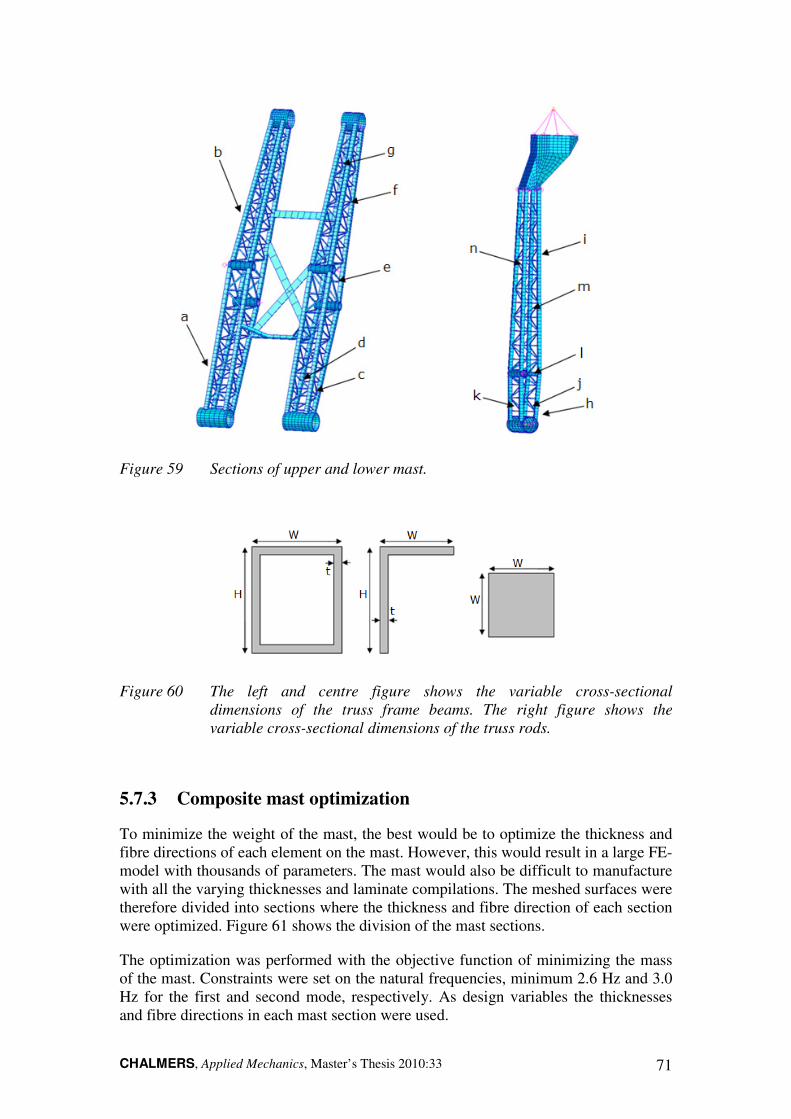
CHALMERS, Applied Mechanics, Master’s Thesis 2010:33 71
Figure 59 Sections of upper and lower mast.
Figure 60 The left and centre figure shows the variable cross-sectional
dimensions of the truss frame beams. The right figure shows the
variable cross-sectional dimensions of the truss rods.
5.7.3 Composite mast optimization
To minimize the weight of the mast, the best would be to optimize the thickness and fibre directions of each element on the mast. However, this would result in a large FE-model with thousands of parameters. The mast would also be difficult to manufacture with all the varying thicknesses and laminate compilations. The meshed surfaces were therefore divided into sections where the thickness and fibre direction of each section were optimized. Figure 61 shows the division of the mast sections.
The optimization was performed with the objective function of minimizing the mass of the mast. Constraints were set on the natural frequencies, minimum 2.6 Hz and 3.0 Hz for the first and second mode, respectively. As design variables the thicknesses and fibre directions in each mast section were used.
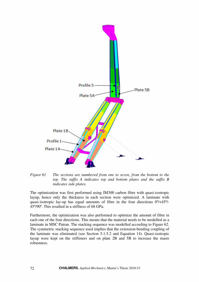
CHALMERS, Applied Mechanics, Master’s Thesis 2010:33 72
Figure 61 The sections are numbered from one to seven, from the bottom to the
top. The suffix A indicates top and bottom plates and the suffix B
indicates side plates.
The optimization was first performed using IM300 carbon fibre with quasi-isotropic layup, hence only the thickness in each section were optimized. A laminate with quasi-isotropic lay-up has equal amounts of fibre in the four directions 0º/+45º/-45º/90º. This resulted in a stiffness of 68 GPa.
Furthermore, the optimization was also performed to optimize the amount of fibre in each one of the four directions. This means that the material needs to be modelled as a laminate in MSC Patran. The stacking sequence was modelled according to Figure 62. The symmetric stacking sequence used implies that the extension-bending coupling of the laminate was eliminated (see Section 5.1.5.2 and Equation 14). Quasi-isotropic layup were kept on the stiffeners and on plate 2B and 5B to increase the masts robustness.
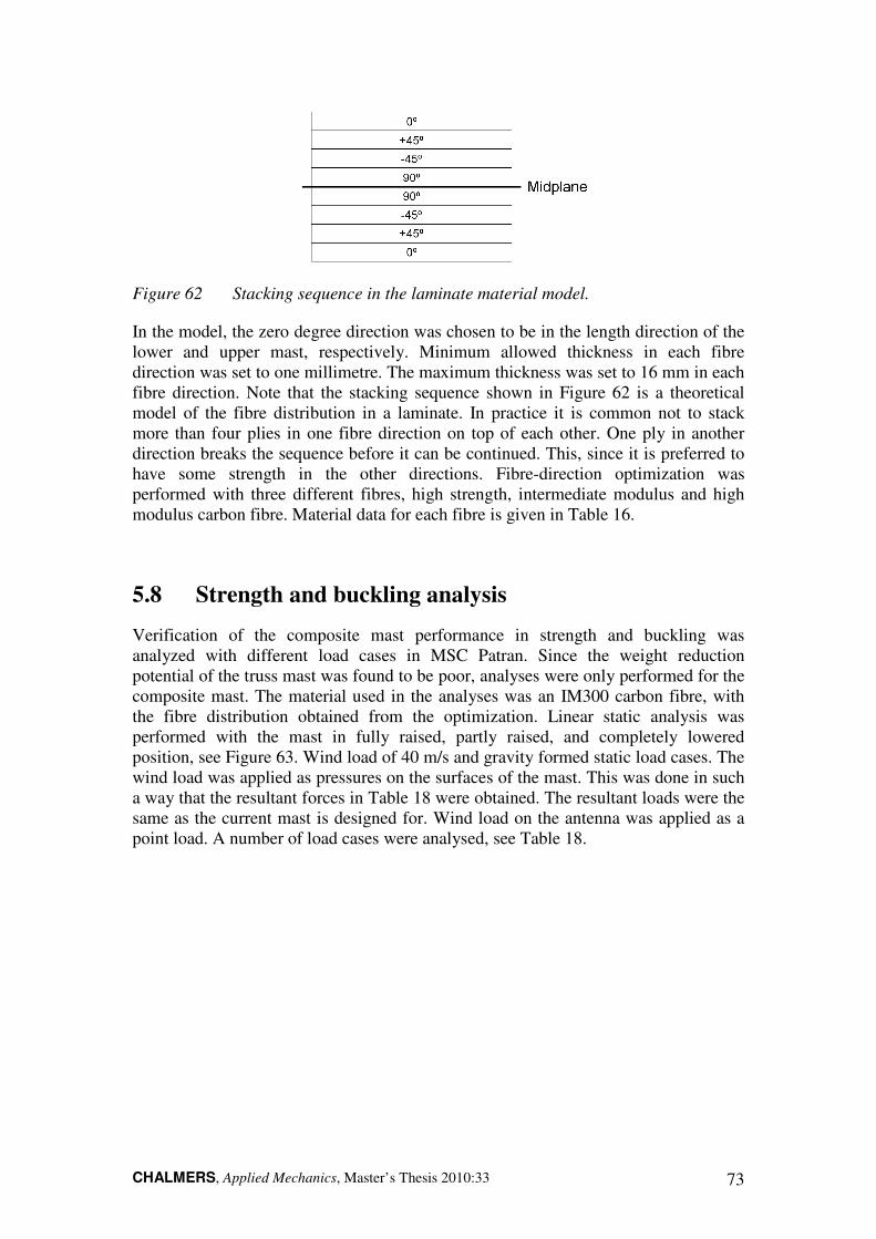
CHALMERS, Applied Mechanics, Master’s Thesis 2010:33 73
Figure 62 Stacking sequence in the laminate material model.
In the model, the zero degree direction was chosen to be in the length direction of the lower and upper mast, respectively. Minimum allowed thickness in each fibre direction was set to one millimetre. The maximum thickness was set to 16 mm in each fibre direction. Note that the stacking sequence shown in Figure 62 is a theoretical model of the fibre distribution in a laminate. In practice it is common not to stack more than four plies in one fibre direction on top of each other. One ply in another direction breaks the sequence before it can be continued. This, since it is preferred to have some strength in the other directions. Fibre-direction optimization was performed with three different fibres, high strength, intermediate modulus and high modulus carbon fibre. Material data for each fibre is given in Table 16.
5.8 Strength and buckling analysis
Verification of the composite mast performance in strength and buckling was analyzed with different load cases in MSC Patran. Since the weight reduction potential of the truss mast was found to be poor, analyses were only performed for the composite mast. The material used in the analyses was an IM300 carbon fibre, with the fibre distribution obtained from the optimization. Linear static analysis was performed with the mast in fully raised, partly raised, and completely lowered position, see Figure 63. Wind load of 40 m/s and gravity formed static load cases. The wind load was applied as pressures on the surfaces of the mast. This was done in such a way that the resultant forces in Table 18 were obtained. The resultant loads were the same as the current mast is designed for. Wind load on the antenna was applied as a point load. A number of load cases were analysed, see Table 18.
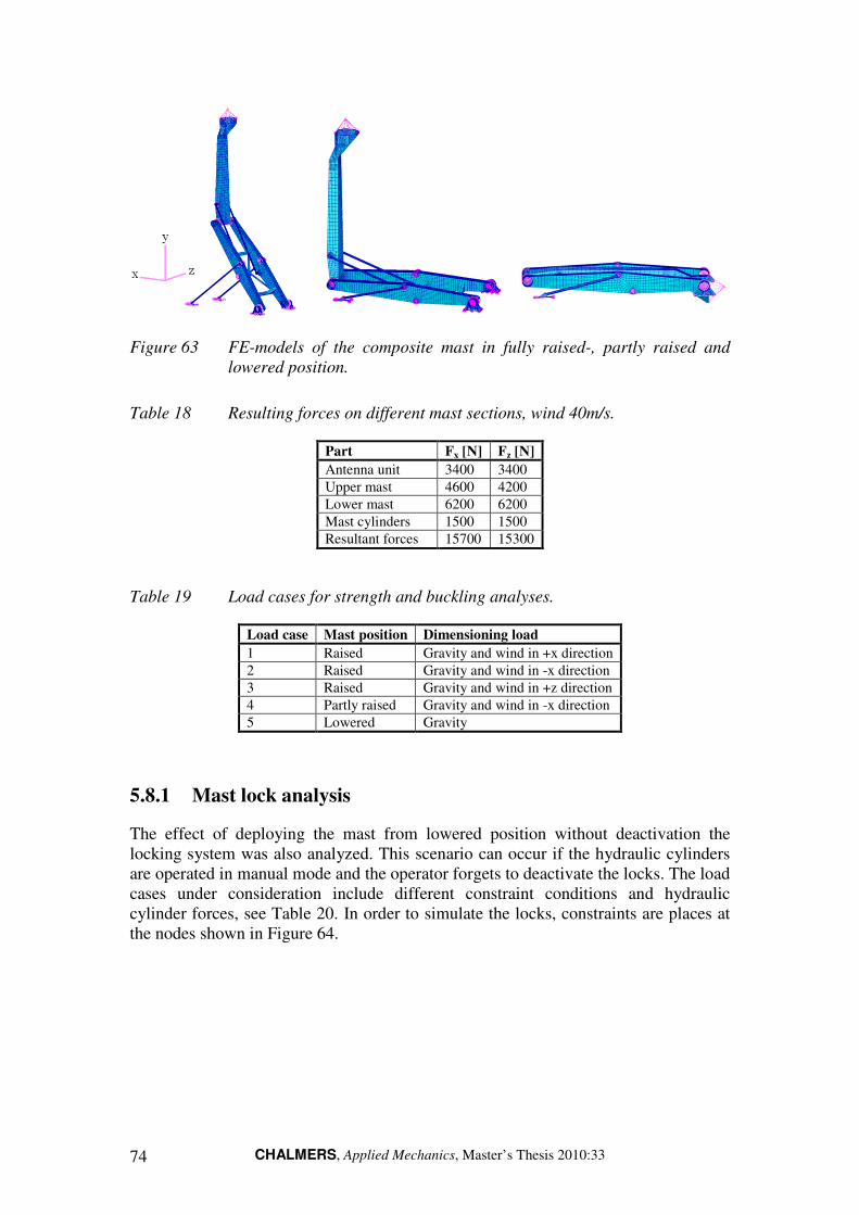
CHALMERS, Applied Mechanics, Master’s Thesis 2010:33 74
Figure 63 FE-models of the composite mast in fully raised-, partly raised and
lowered position.
Table 18 Resulting forces on different mast sections, wind 40m/s.
Part Fx [N] Fz [N]
Antenna unit 3400 3400
Upper mast 4600 4200
Lower mast 6200 6200
Mast cylinders 1500 1500
Resultant forces 15700 15300
Table 19 Load cases for strength and buckling analyses.
Load case Mast position Dimensioning load
1 Raised Gravity and wind in +x direction
2 Raised Gravity and wind in -x direction
3 Raised Gravity and wind in +z direction
4 Partly raised Gravity and wind in -x direction
5 Lowered Gravity
5.8.1 Mast lock analysis
The effect of deploying the mast from lowered position without deactivation the locking system was also analyzed. This scenario can occur if the hydraulic cylinders are operated in manual mode and the operator forgets to deactivate the locks. The load cases under consideration include different constraint conditions and hydraulic cylinder forces, see Table 20. In order to simulate the locks, constraints are places at the nodes shown in Figure 64.

CHALMERS, Applied Mechanics, Master’s Thesis 2010:33 75
Figure 64 Constraints simulating the front and rear locking devices.
Table 20 Load cases for mast lock analysis.
Load Case
Upper cylinder force [kN]
Lower cylinder force [kN]
Front locking device
Rear locking device
1 -117 – Locked Unlocked
2 – -86 Locked Unlocked
3 -117 – Unlocked Locked
4 – -86 Unlocked Locked
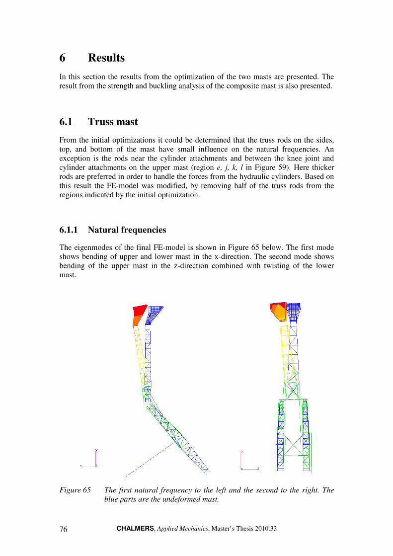
CHALMERS, Applied Mechanics, Master’s Thesis 2010:33 76
6 Results
In this section the results from the optimization of the two masts are presented. The result from the strength and buckling analysis of the composite mast is also presented.
6.1 Truss mast
From the initial optimizations it could be determined that the truss rods on the sides, top, and bottom of the mast have small influence on the natural frequencies. An exception is the rods near the cylinder attachments and between the knee joint and cylinder attachments on the upper mast (region e, j, k, l in Figure 59). Here thicker rods are preferred in order to handle the forces from the hydraulic cylinders. Based on this result the FE-model was modified, by removing half of the truss rods from the regions indicated by the initial optimization.
6.1.1 Natural frequencies
The eigenmodes of the final FE-model is shown in Figure 65 below. The first mode shows bending of upper and lower mast in the x-direction. The second mode shows bending of the upper mast in the z-direction combined with twisting of the lower mast.
Figure 65 The first natural frequency to the left and the second to the right. The
blue parts are the undeformed mast.

CHALMERS, Applied Mechanics, Master’s Thesis 2010:33 77
The result of the optimization of the final FE-model is given in Table 21. As seen in the table the optimal geometry is frame beams with large cross-section, which gives high bending stiffness. The rods between the knee joint and the upper cylinder attachment should also be thick (W = 21 mm). It is seen that the weight of the upper and lower mast is 716 kg which corresponds to 103% of the current upper and lower mast. An optimization was also performed with the frame beams maximum width and height constrained to 70mm and the thickness to 6mm. This is to force the optimization algorithm to increase the width of the truss rods and to avoid impractical large dimensions of the truss frame beams.
The results from this constrained optimization are also given in Table 21. The truss rod dimensions were increased compared to the unconstrained analysis, while the frame beams approaches their maximum allowed value. The mass of this mast configuration increases to 812 kg (117% of the current mast). An optimization was also performed with the frame beam switched to L-profiles. Using L-profiles resulted in a mast weight of 976 kg (140% of the current mast). Based on the result from the optimization it was concluded that no weight reduction is possible with the truss mast concept. The second natural frequency is still lower than what is desired. The stiffness of the mast must be raised to obtain the desired frequencies, this will most likely increase the weight of it. The low potential of the truss mast concepts was the reason for not performing strength and buckling analyses.
Table 21 Optimized dimensions of the truss mast.
Unconstrained optimization Constrained frame beams
Optimized dimensions [mm] Optimized dimensions [mm]
Lower Mast W H t W H t
a-lower frame beams 53 78 3 59 67 4
b-upper frame beams 105 92 3 69 69 6
c-lower rods (sides) - - 12 - - 13
d-lower rods (top&bottom) - - 7 - - 10
e-rods near hydraulics - - 12 - - 16
f-upper rods (sides) - - 11 - - 13
g-upper rods (top&bottom) - - 8 - - 10
Upper Mast
h-lower frame beams 75 102 6 70 70 6
i-upper frame beams 67 157 3 66 70 6
j-lower rods (sides) - - 21 - - 16
k-lower rods (top&bottom) - - 8 - - 9
l-rods near hydraulics - - 17 - - 22
m-upper rods (sides) - - 10 - - 12
n-upper rods (top&bottom) - - 6 - - 8
fx [Hz] 2.6
2.6
fz [Hz] 2.67 2.65
Mass3 [kg] 716 812
Mass (% of current mast) 103 117
3 Mass of lower and upper mast. The mass of the antenna unit, bearings, and hydraulic cylinders are excluded.

CHALMERS, Applied Mechanics, Master’s Thesis 2010:33 78
6.2 Composite mast
In this section are the results from the optimization and analysis of the composite mast presented.
6.2.1 Natural frequency
The optimization had the objective of minimizing mass for the given natural frequencies 2.6 Hz in the first mode and 3.0 Hz in the second. The thickness of the plates were optimized and resulted in a weight reduction of 39.7% for the carbon fibre with quasi-isotropic laminates. The first and second mode can be seen in Figure 66 and the deformation is similar as for the truss mast. The optimization showed that the mast needs high stiffness around the cylinder attachments. This resulted in thick plates close to the attachments. In addition to this, it is preferable to place as much material as possible in the corners of the cross-section, hence glue profiles with high thickness. From the initial analysis the modifications in Figure 57 were performed to improve the stiffness around the cylinder attachments. This resulted in a weight reduction of 43.7%.
Figure 66 The first natural frequency to the left and the second to the right. The
blue meshed parts are the undeformed mast.
The optimization with both fibre directions and laminate thicknesses as parameters resulted in further reduced weight, see Table 22. Note that the weight reduction values in the table are valid for the sum of lower and upper mast, originally 696 kg.
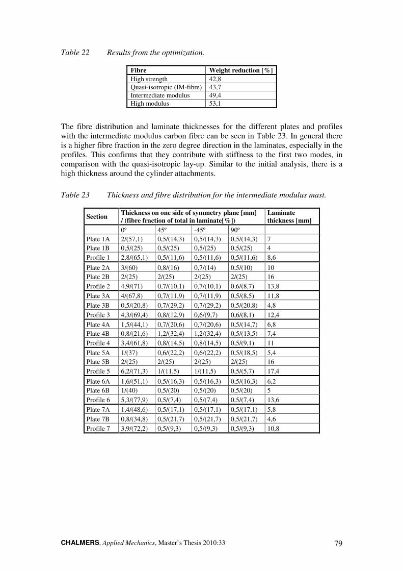
CHALMERS, Applied Mechanics, Master’s Thesis 2010:33 79
Table 22 Results from the optimization.
Fibre Weight reduction [%]
High strength 42,8
Quasi-isotropic (IM-fibre) 43,7
Intermediate modulus 49,4
High modulus 53,1
The fibre distribution and laminate thicknesses for the different plates and profiles with the intermediate modulus carbon fibre can be seen in Table 23. In general there is a higher fibre fraction in the zero degree direction in the laminates, especially in the profiles. This confirms that they contribute with stiffness to the first two modes, in comparison with the quasi-isotropic lay-up. Similar to the initial analysis, there is a high thickness around the cylinder attachments.
Table 23 Thickness and fibre distribution for the intermediate modulus mast.
Section Thickness on one side of symmetry plane [mm] / (fibre fraction of total in laminate[%])
Laminate thickness [mm]
0º 45º -45º 90º
Plate 1A 2/(57,1) 0,5/(14,3) 0,5/(14,3) 0,5/(14,3) 7
Plate 1B 0,5/(25) 0,5/(25) 0,5/(25) 0,5/(25) 4
Profile 1 2,8/(65,1) 0,5/(11,6) 0,5/(11,6) 0,5/(11,6) 8,6
Plate 2A 3/(60) 0,8/(16) 0,7/(14) 0,5/(10) 10
Plate 2B 2/(25) 2/(25) 2/(25) 2/(25) 16
Profile 2 4,9/(71) 0,7/(10,1) 0,7/(10,1) 0,6/(8,7) 13,8
Plate 3A 4/(67,8) 0,7/(11,9) 0,7/(11,9) 0,5/(8,5) 11,8
Plate 3B 0,5/(20,8) 0,7/(29,2) 0,7/(29,2) 0,5/(20,8) 4,8
Profile 3 4,3/(69,4) 0,8/(12,9) 0,6/(9,7) 0,6/(8,1) 12,4
Plate 4A 1,5/(44,1) 0,7/(20,6) 0,7/(20,6) 0,5/(14,7) 6,8
Plate 4B 0,8/(21,6) 1,2/(32,4) 1,2/(32,4) 0,5/(13,5) 7,4
Profile 4 3,4/(61,8) 0,8/(14,5) 0,8/(14,5) 0,5/(9,1) 11
Plate 5A 1/(37) 0,6/(22,2) 0,6/(22,2) 0,5/(18,5) 5,4
Plate 5B 2/(25) 2/(25) 2/(25) 2/(25) 16
Profile 5 6,2/(71,3) 1/(11,5) 1/(11,5) 0,5/(5,7) 17,4
Plate 6A 1,6/(51,1) 0,5/(16,3) 0,5/(16,3) 0,5/(16,3) 6,2
Plate 6B 1/(40) 0,5/(20) 0,5/(20) 0,5/(20) 5
Profile 6 5,3/(77,9) 0,5/(7,4) 0,5/(7,4) 0,5/(7,4) 13,6
Plate 7A 1,4/(48,6) 0,5/(17,1) 0,5/(17,1) 0,5/(17,1) 5,8
Plate 7B 0,8/(34,8) 0,5/(21,7) 0,5/(21,7) 0,5/(21,7) 4,6
Profile 7 3,9/(72,2) 0,5/(9,3) 0,5/(9,3) 0,5/(9,3) 10,8
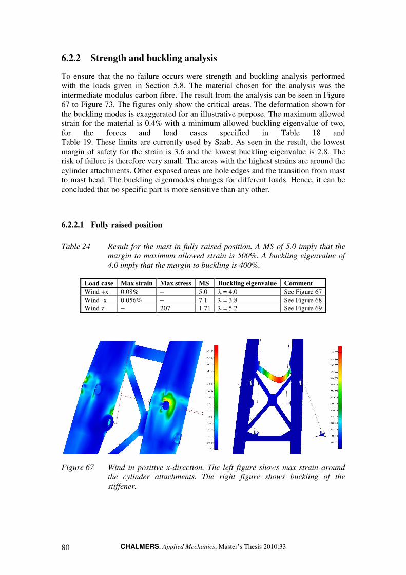
CHALMERS, Applied Mechanics, Master’s Thesis 2010:33 80
6.2.2 Strength and buckling analysis
To ensure that the no failure occurs were strength and buckling analysis performed with the loads given in Section 5.8. The material chosen for the analysis was the intermediate modulus carbon fibre. The result from the analysis can be seen in Figure 67 to Figure 73. The figures only show the critical areas. The deformation shown for the buckling modes is exaggerated for an illustrative purpose. The maximum allowed strain for the material is 0.4% with a minimum allowed buckling eigenvalue of two, for the forces and load cases specified in Table 18 and Table 19. These limits are currently used by Saab. As seen in the result, the lowest margin of safety for the strain is 3.6 and the lowest buckling eigenvalue is 2.8. The risk of failure is therefore very small. The areas with the highest strains are around the cylinder attachments. Other exposed areas are hole edges and the transition from mast to mast head. The buckling eigenmodes changes for different loads. Hence, it can be concluded that no specific part is more sensitive than any other.
6.2.2.1 Fully raised position
Table 24 Result for the mast in fully raised position. A MS of 5.0 imply that the
margin to maximum allowed strain is 500%. A buckling eigenvalue of
4.0 imply that the margin to buckling is 400%.
Load case Max strain Max stress MS Buckling eigenvalue Comment
Wind +x 0.08% – 5.0 λ = 4.0 See Figure 67
Wind -x 0.056% – 7.1 λ = 3.8 See Figure 68
Wind z – 207 1.71 λ = 5.2 See Figure 69
Figure 67 Wind in positive x-direction. The left figure shows max strain around
the cylinder attachments. The right figure shows buckling of the
stiffener.

CHALMERS, Applied Mechanics, Master’s Thesis 2010:33 81
Figure 68 Wind in negative x-direction. The left figure shows max strain around
the cylinder attachments. The right figure shows buckling of the upper
mast.
Figure 69 Wind in z-direction. The left figure shows max stress in the steel foot.
The right figure shows buckling of the lower hydraulic cylinders.
6.2.2.2 Partly raised position
Table 25 Result for the mast in partly raised position.
Load case Max strain MS Buckling eigenvalue Comment
Wind +x 0.055% 7.3 λ = 8.5 See Figure 70

CHALMERS, Applied Mechanics, Master’s Thesis 2010:33 82
Figure 70 Wind in positive x-direction. The left figure shows max strain at the
mast head. The right figure shows buckling of the lower mast.
6.2.2.3 Lowered position
Table 26 Result for the mast in lowered position.
Load case Max strain MS Buckling eigenvalue Comment
Gravity 0.065% 6.2 λ = 2.8 See Figure 71
Figure 71 Gravity load only. The left figure shows max strain at the cylinder
attachment. The right figure shows buckling of the upper mast.
6.2.3 Mast lock analysis
Strength analysis of the mast was performed to examine the effect of deploying the mast with the mast locks enabled. Four different load cases were considered, see Table 20. The result from this analysis is given in Table 27. It can be seen that high stresses are present in the knee joint for load case 1 and 2. The cylinder attachments and the mast head are areas with high stresses for load case 3 and 4.

CHALMERS, Applied Mechanics, Master’s Thesis 2010:33 83
Table 27 Result from the mast lock analysis, load cases are specified in Table 20.
Load case Max strain Max stress MS Comment
1 – 175 MPa - See Figure 72
2 – 125 MPa - See Figure 72
3 0.11% – 3.6 See Figure 73
4 0.059% – 6.8 See Figure 73
Figure 72 The figures show max stress in the aluminium knee joint. The left figure
is load case 1 and the right figure is load case 2.
Figure 73 The left figure shows max strain at the cylinder attachments, load case
3. The right figure shows max strain at the mast head, load case 4.

CHALMERS, Applied Mechanics, Master’s Thesis 2010:33 84
6.2.4 Cost estimation
Table 28 shows the cost estimation for the composite mast with the different types of carbon fibre. Only the bulk material price for the carbon fibre was considered. Manufacturing costs were not included since it was difficult to estimate and outside the scope of this project. It can be seen that the cost for increased weight reduction is high. Cost per reduced kilo is calculated as the material cost for the carbon fibre, minus the material costs for the current mast, divided by the weight reduction in kilogram (see Equation 39). The material cost for the current mast is calculated based on a weight of 573 kg, this excludes joints and cylinder attachments. With a steel price of 22 kr/kg, this gives a material cost of 12 606 kr (Tibnor 2010).
There will be some costs for the steel cylinder attachments and the aluminium joints. However the cost for the aluminium was not found and it was thereof excluded in the cost estimation.
Table 28 Weight and material cost for the composite mast.
Fibre Weight reduction [%]
Total weight of lower & upper mast [kg]
CFRP only [kg]
Material cost [kr/kg]
Material cost [kr]
Cost per reduced kilo [kr/kg]
HS300 42.8 398.1 274.9 341 93 752 272
IM300 (QI4) 43.7 391.8 268.6 739 198 416 611
IM300 49.4 352.2 229 739 169 157 455
HM300 53.1 326.4 203.2 1044 212 114 540
Cost per reduced kilo [kr/kg] = ykg
krx
−
−
696
12606 (39)
x = Material cost [kr] y = Total weight of lower & upper mast [kg]
4 QI = Quasi-isotropic lay-up.

CHALMERS, Applied Mechanics, Master’s Thesis 2010:33 85
7 Discussion
From the results it can be seen that the optimized steel truss mast gave an increase in weight of 3% for unrestricted dimensions. The truss frame beam dimensions for this mast configuration became quite large. Therefore were constraints on maximum dimensions used. However, this increased the weight even more and resulted in a weight of 117% of the original. Attempts with aluminium were performed, this did not give any weight reduction. It can be explained by the lower stiffness to weight ratio in pure tension and compression, compared to steel.
Nevertheless, it should be noticed that this concept compete with a mast of the same material with a design that already is optimized. To model the local flexibilities in the welded joint are difficult. This means that the FE-model will be stiffer than the manufactured mast. Therefore, it may be desired to have some margin of safety. The low weight reduction potential for the truss mast is the reason for not performing further analysis regarding strength and buckling.
The advantages of a truss structure will become more obvious if the limits on allowed maximum dimensions of the mast are higher. Kept plate thicknesses for the current mast but with increased width and height may lead to buckling issues. In that case a truss structure will be more suitable. The effect of moving area to the corners of the cross-section will also be more apparent. A truss mast would furthermore require extra systems to protect the waveguide and to shield the electromagnetic fields generated by the cables.
The composite mast gave a weight reduction of 42.8-53.1% depending on laminate structure and specific fibre. This is mainly due to the high stiffness to weight ratio of the material. Hence, the objective of a 50% weight reduction can be seen as fulfilled. The strength and buckling analysis showed that very low risk of laminate failure exists. This can be explained by the increased dimensions that are needed to obtain the desired natural frequencies. The bending stiffness of a plate is cubically dependent of the thickness. An increase in thickness therefore radically increases the bending stiffness and as a result lowers the risk of buckling. The usage of carbon fibre is also promising from a service life perspective, since the fatigue limit is as high as 90% of the tensile strength compared to about 45% for steel.
The SE 84LV epoxy prepreg system from Gurit SP High Modulus is chosen for the composite mast. Several other prepreg systems were also evaluated. The reason for choosing this particular system is that data for the system with different reinforcing fibres were available. Such data can otherwise be hard to find. The risk of impact damages may be an issue if a composite material is used, especially during manual removal of ice. The SE 84LV prepreg system has a toughened matrix which improves the impact strength and reduces the risk of damages from ice removal.
Carbon fibre is unable to undergo plastic deformation, no stress relief around hole edges is possible. In the work this has been accounted for by using a maximum allowed strain of 0.4%, which is lower than the actual strain-to-failure of the material. Furthermore, this introduces safety against possible damages in the laminate. The robustness was additionally improved with increased material thickness around hole edges using a quasi-isotropic laminate. The same precaution was utilized on the

CHALMERS, Applied Mechanics, Master’s Thesis 2010:33 86
stiffener. Glass fibre can also be used at these places since they have higher strain-to-failure. Moreover, glass fibre has electrical isolation properties and can therefore be a barrier in the carbon fibre/metal interfaces to avoid galvanic corrosion. The oxide layer on the aluminium also has an isolating effect.
For the steel parts, the same material is used as for the current mast. The peak level of stress in the aluminium parts occur in the knee joint when the upper mast is raised with the front locking device enabled, see Figure 72. Stresses in the joint reaches 175 MPa, which is quite high. Since some margin of safety is desired, the knee joint can either be reinforced around the hole or aluminium with high yield strength can be used. In the latter case, the 7020-T6 aluminium is suitable. It is used for military purposes has a yield strength of 335 MPa. Hence, giving a margin of safety of 1.91. The 7020-T6 alloy is commonly used in welded applications and has a high resistance against stress corrosion. Furthermore, its high fatigue strength conforms to the demand of a 20 year service life (Aluminium matter). Note that the mast lock simulation is highly simplified. Since no mast locks were included in the models, the hole nodes at the knee joint were constrained instead. This results in a more severe deformation of the knee joint than what actually would occur.
The FE-model for the composite mast was to some extent simplified. One example of this are the sections used for dividing the mast, see Figure 61. Since the number of sections that were optimized is relatively few, the difference in thickness between some sections is large. This was done to speed up the calculations and to receive a graspable amount of variables. Smaller sections would result in finer thickness transitions and more accurate fibre fractions in each direction.
Another example of a simplification in the FE-model is the glue profiles. In the FE-model the glue profile and plate is represented by one thickness, as seen in Figure 74. The physical mast will have fixed dimensions on the glue profiles while the plate’s thickness is variable. The plates and the glue profiles also share the same mid-surface in the FE-model. The justification for the design in the FE-model is that it creates a coherent mid-surface which is easier to mesh. It should also be pointed out that the CAD-models are not updated with the result from the FE-calculations.
Figure 74 The left figure shows the simplified glue profile design used in the FE-
model. The right figure shows the intended glue profile design.

CHALMERS, Applied Mechanics, Master’s Thesis 2010:33 87
In the results it can be seen that the highest fibre fraction in one direction in a laminate is 77.9%. The minimum amount of fibre in one direction is 5.7%. This is since the optimization was performed for the first and second natural frequency. The high amount of fibre in one direction can make the mast sensitive for unpredicted load cases. Therefore it may be desired to narrow the fibre fraction range in each direction to about 10-70%. This would assure a minimum and maximum amount of fibre in each direction.
Since the project focus was the mechanical performance of the mast, some aspects were excluded in the work. The installation of cables and waveguide has not been considered in the models. The mast also has to be modified to some extent to cope with the EMC requirements. It is likely that shielding of cables and waveguide is required. An extra system for lightning protection is also required. Some of the environmental requirements has however been excluded. An example is the resistance against manual ice removal. It is difficult to verify this requirement without mechanical testing.
If the restrictions on kept interfaces to joints and cylinders are loosened it might be possible to introduce a new more effective design that further could lower the weight. The design will still be limited as a result of the waveguide. Its function is to transfer waves from the wave generator, located in the shelter, to the antenna. The waveguide is a copper tube going through the upper and lower mast, merged by a revolved joint in the knee joint. It is unfortunately not possible to design the waveguide in any other way. This limits some of the otherwise possible designs of the mast. If the wave generator was moved to the antenna, new designs would be possible. Including the wave generator in the antenna will make it heavier. This would require a stiffer and likely heavier mast, to obtain the desired natural frequencies.
The lowered weight of the mast will lead to weight reduction potential of the other components such as the shelter. Increased utilization of materials such as carbon fibre in the Giraffe AMB system may enable new ways of transportation with for instance helicopter.

CHALMERS, Applied Mechanics, Master’s Thesis 2010:33 88
8 Conclusions
The aim of the present work was to investigate two possible solutions, one utilizing metallic material and one utilizing composite materials. These concepts were developed to fulfil the same requirements as the current mast.
It is concluded that no weight reduction is possible with the steel truss mast. In fact the truss mast gave an increase in weight. Other drawbacks with this mast are manufacturing and maintenance aspects. The main idea with the truss mast was a lighter mast with less projected area for the wind load. Based on the result that no weight reduction is possible, together with the other drawbacks, the truss mast is concluded to be unsuccessful.
The results from the truss mast calculations lead to the conclusion that the current mast design is optimal when metallic materials are used. If all the mechanical interfaces are kept it is difficult to find a design that gives better lightweight performance.
If the mast is designed using composite materials, the weight reduction potential is high. Preliminary results indicate that a weight reduction up to 53% is possible. Strength and buckling analyses shows a high margin of safety against laminate failure. Material data for the chosen composite prepreg system also indicates that the mast fulfils the environmental requirements. Due to the excellent fatigue properties and high margin of safety it can be concluded that the mast will survive the design lifetime of 20 years. The high fatigue strength of the chosen aluminium also corresponds to this demand. In addition to this, the 7020-T6 aluminium properties also suits the other requirements set on the material.
The preliminary weight reduction obtained for the composite mast is likely to be reduced if the mast is modified to fulfil requirement of EMC, lightning protection and installation of cables and waveguide. The high fibre fraction in one direction may have to be reduced to increase the robustness of the mast.
Finally it is concluded that the increased weigh reduction using high-modulus fibre has a high price. The weight when using high strength and high modulus carbon fibre differs with about 70kg, while the difference in cost is more than 10 000£. The large quantities of carbon fibre are likely to give a bulk discount from the supplier, but the cost relation between the different fibres can be seen as fixed.
This work furthermore shows how the great mechanical performance of composite materials can be used in lightweight design of a load-carrying structure. The choice of design, manufacturing method and specific laminate are closely related. It is seen that the anisotropic material properties of composite materials make calculation and material modelling more difficult. However, the anisotropy also makes the material possible to be tailor-made for the specific application. The experience gained from this project can be used for designing other Saab products using composite material. This in particular applies to optimization and analysis of composite structures using MSC Patran/Nastran.
CHALMERS, Applied Mechanics, Master’s Thesis 2010:33 89
8.1 Recommendations
Recommendations for future work are that the composite mast should be divided into smaller sections to better display where the material is needed. The number of sections depends on what can be seen as defensible both out of a manufacturing and cost perspective.
The FE-model should be further developed so that holes for cables and waveguide installation are included. More accurate modelling of the glue profiles should also be considered. A lower and upper fibre fraction limit in each direction is also recommended to be used in the optimization. Since only the parts in carbon fibre have been optimized, the possibility of weight reduction of feet- and knee joints should be examined.
Furthermore, proper shielding of cables and waveguide must be done to fulfil EMC requirements. Once a specific material is chosen, material testing must be carried out to assure the properties of the material. Testing of the impact strength must secure that mechanical removal of ice is possible without damaging the material.
The introduction of a lightweight mast in Giraffe AMB enables weight reduction of other systems. These possibilities are recommended to be investigated. Extensive use of composite materials in the Giraffe AMB system may enable a significant improvement in the mobility, such as transportation with helicopter.
The final recommendation is to select the high strength carbon fibre. It provides most value for money. If higher modulus fibres are used, the weight reduction is small, but the increase in material cost is dramatic. The fibre should be used together with the SE 84LV epoxy prepreg system since they together fulfil the demands. Further investigation can be done to analyze if any other epoxy have superior fulfilment of the requirements. For the joints, the 7020-T6 aluminium is recommended.
In the end it comes to the question of how much more the customer is willing to spend for the weight reduction of the mast.

CHALMERS, Applied Mechanics, Master’s Thesis 2010:33 90
9 References
Aluminium matter (2010) http://aluminium.matter.org.uk (25 May 2010).
Ashby, M.F. (2005) Materials Selection in Mechanical Design. [Electronic] Butterworth-Heinemann, Amsterdam ; Boston, 2005. (ISBN: 9780080523965).
Cambridge Engineering Selector, computer program, (2010).
Christensen, P.W., Klarbring, A. (2009). An introduction to structural optimization, (Solid mechanics and its applications Vol. 153), Springer, Dordrecht, The Netherlands (ISBN: 978-1-4020-8665-6).
Donaldson, S.L., Miracle D.B. (2010). ASM Handbook. Vol. 21 [Electronic], ASM International 2010.
Ewins, D.J. (1984) Modal testing: Theory and practise, 2nd edition, Research Studies Press, Baldock, The US (ISBN: 0-86380-218-4).
Gay, D., Hoa, S.V., Tsai, S.W. (2003) Composite materials design and applications,
CRC, Boca Raton, The US (ISBN: 1-58716-084-6).
Johannesson, H., Persson, J-G., Petterson, D. (2004) Produktutveckling – effektiva
metoder för konstruktion och design (Product development - efficient methods for product development and design. In Swedish), Liber, Stockholm, Sweden (ISBN: 91-47-05225-2).
Lindahl, J. (2008) Structural analysis of Giraffe mast structure, Saab AB, Göteborg,
Sweden.
Mallick, P.K. (2008) Fiber reinforced composites Materials - Manufacturing and
Design, 3rd edition, CRC Press, Boca Raton, The US (ISBN: 9780849342059).
Ryshwalski, R. (2009) Thermosetting polymers, Hand-out in the course Materials for lightweight design, Department of Material and Manufacturing Technology, Chalmers University of Technology, Göteborg, Sweden.
Matthews, F.L., Davies, G.A.O., Hitching, D., Soutis, C. (2000) Finite element
modeling of composite materials and structures, Woodhead Pub., Cambridge, England, pp 3-36. (ISBN: 0849308461).
Megson, T.H.G. (1999) Aircraft structures for engineering students, 3rd edition,
Arnold Publishers, London, England (ISBN: 0 340 70 588 4).
Norell, M. (1999) Aluminium alloys, Hand-out in the course Materials for lightweight design, Department of Material and Manufacturing Technology, Chalmers University of Technology, Göteborg, Sweden.
Ottosen, N., Petersson, H. (1992) Introduction to the finite element method, Prentice Hall, Harlow, England (ISBN-13: 978-0-13-473877-2).

CHALMERS, Applied Mechanics, Master’s Thesis 2010:33 91
Saab Group (2010) http://www.saabgroup.com (24 May 2010).
Schaeffer, H.G. (1984) MSC/NASTRAN Prime–Static and Normal Modes Analysis, 4th printing, Schaeffer Analysis Inc, Mont Vernon, The US (Library of congress number: 79-63973).
Sundström, B. (1998) Handbok och formelsamling i Hållfasthetslära, (Handbook and formulary in mechanics. In Swedish), Department of Mechanics, The Royal Institute of Technology, Stockholm, Sweden.
Tibnor (2010) http://www.tibnor.se (4 June 2010).
Vinson, R., Sierakowski, R.L. (2002) The Behavior of Structures Composed of
Composite Materials, 2nd edition, (Solid mechanics and its applications Vol. 105), Kluwer Academic Publishers, Dordrecht, The Netherlands (ISBN: 1-4020-0904-6).

CHALMERS, Applied Mechanics, Master’s Thesis 2010:33 92
Appendix A: Specification of requirements
This document specifies the requirements for the design of a lightweight mast for the Giraffe AMB radar system. The construction is based on the current mast, IPC10104/1. This product is given the number INXM1010001/1.
For concept evaluation purposes the requirements are listed as strict requirements (Req) and desired properties (Dp). The importance of a desired property is classified in a scale 1-5, where 1 is low importance and 5 high importance. The verification method is also included.
1 Design
1.1 Req: Geometry
The mast should be mounted on the roof of the Giraffe AMB shelter and fit within its boundaries. Furthermore is the height limited since the shelter together with the mast in folded position should be possible to transport as a container. A drawing of the available space is shown in Figure 75 below. Detailed CAD drawings of the Giraffe AMB shelter and the current mast are available. The mast should be 7893 mm high in raised condition, measured from the roof of the shelter to the turn table interface.
Verification: Measurements in CAD-model.
Figure 75 Available space on the Giraffe AMB shelter. Left figure is view from the
bottom and right view from the side.

CHALMERS, Applied Mechanics, Master’s Thesis 2010:33 93
1.2 Dp: Mechanical interfaces
It is desired to keep all the mechanical interfaces of the new mast on the same positions as before. The mechanical interfaces are:
• Attachment of the lower mast to the shelter.
• Lower hydraulic cylinder attachment points to the shelter and lower mast.
• Upper hydraulic cylinder attachment points to upper and lower mast.
• Position and design of the knee joint between upper and lower mast.
• Mast head attachment to upper mast.
Verification: CAD-model.
Importance: 4
1.3 Dp: High weight reduction
The aim with the lightweight mast is to reduce the weight with 20% using metallic materials and 50% using composite materials, compared to the current mast.
Verification: Measurements in CAD- or FE model.
Importance: 5
1.4 Dp: Low projected area
The mast should have lower projected area, Ap, than the current solution, see Table 29. This is to reduce the wind load on the structure.
Table 29 Static wind loadings as resultant forces in x- and z-direction at 40 m/s.
Part Cd Apx (m2) Fx (N) Apz (m
2) Fz (N)
Antenna unit 1.6 2.2 3400 2.2 3400
Upper mast 2 2.2 4600 2.0 4200
Lower mast 2 3.0 6200 3.0 6200
Mast cylinders 1.2 1.2 1500 1.2 1500
Resultant forces 15700 15300
Verification: Measurements in CAD-model.
Importance: 5
CHALMERS, Applied Mechanics, Master’s Thesis 2010:33 94
1.5 Dp: Low complexity
Solutions using a low grade of complexity are desired. Low complexity means:
• Minimum number of components.
• Minimum number of different components.
• Minimum number of interfaces.
• Use of simple geometries.
2 Functions of the mast
2.1 Req: Locking system
It should be possible to lock the mast against the shelter during transportation. The locking device should withstand an attempt to raise the mast without deactivating the locking system.
Verification: FEM calculations.
2.2 Req: Cabling
Attachment of cables and waveguide to the mast should be possible.
Verification: Material data, CAD-model.
3. Environmental aspects
3.1 Req: Surface temperature
The mast should be possible to operate in ambient temperatures from -46°C to 55°C. In addition 1120 W/m2 solar radiation is included. This gives a maximum surface temperature of ≈ 110°C.
Standard: STANAG 2895 categories A1, A2, A3, B1, B2, B3, C0, C1 and C2.
Verification: Material data.
CHALMERS, Applied Mechanics, Master’s Thesis 2010:33 95
3.2 Req: Outdoor exposure
The mast must withstand exposure to outdoor exposure. This includes exposure to rain, snow, hail, sandstorms etc. No degradation in performance from environmental exposure is allowed during the design lifetime of 20 years.
Verification: Material data.
3.3 Req: Ice Resistance
The mast shall be designed to withstand 13 mm ice thickness. Ice deposits on the mast must be possible to remove.
Standard: MIL-STD-810F, Method 521.2.
Verification: Material data.
3.4 Dp: Manual ice removal
Manual mechanical removal of ice from the mast without damaging the structure is desired.
Verification: Material data.
Importance: 2
3.5 Req: Lightning strike protection
The mast should have the function of leading away a direct lightning strike on the mast i.e. it should have a connection to earth.
Verification: Electrical conductivity of the mast.
4 Mechanical properties
4.1 Req: Natural frequency requirements
The lowest natural frequency of the mast in deployed position should be at least 2.6 Hz and 3.0 Hz in the x- and z-direction, respectively. This is to avoid resonance of the whole system including the shelter.
Verification: FEM calculations.

CHALMERS, Applied Mechanics, Master’s Thesis 2010:33 96
4.2 Dp: High natural frequency
Designs with a higher natural frequency than specified are desired. A higher natural frequency gives a margin against resonance.
Verification: FEM calculations.
Importance: 3
4.3 Req: Loads
The mast should support the weight of the antenna unit that should be mounted on the top of the mast. The weight of the antenna unit including turn table is 560 kg.
The mast should also withstand a wind load of 40 m/s. Different positions of the mast must be considered, i.e. raised, partly raised and completely lowered position.
Verification: FEM calculations.
4.4 Dp: Large strength margin
The mast should have a large margin against yielding for the specified loads.
Verification: FEM calculations.
4.5 Req: High buckling resistance
The mast should be designed to avoid local buckling and have a safety margin of minimum 100%.
Verification: FEM calculations.
5. Material
5.1 Req: Corrosion resistance
Materials used in the mast shall be corrosion-resistant or given a corrosion-resistant treatment or coating. No degradation in safety, performance and function due to corrosion is allowed during the design lifetime of the mast.
Verification: Material data.

CHALMERS, Applied Mechanics, Master’s Thesis 2010:33 97
5.2 Dp: High Toughness
It is desired to have sufficient toughness of the mast to withstand rough treatment
during transportation etc. Minimum fracture toughness K1C = 10 .mMPa
Verification: Material data.
Importance: 3
5.3 Req: Stiffness and strength
The material must have sufficient strength and stiffness. To low values would give a very thick structure to get the desired properties. Minimum values: E = 40 GPa,
σy =100 MPa.
Verification: Material data.
5.4 Req: Fire Resistance
The mast shall not contain substances or components that may cause fire.
Verification: Material data.
5.5 Dp: Dangerous Substances
The product shall, if possible, not contain components, substances or materials, that each or in combination can be hazardous to personnel, property or environment when the product is operating, maintained, transported, stored or under disposal. If dangerous substances are used they shall be declared.
Verification: Material data.
Importance: 3

CHALMERS, Applied Mechanics, Master’s Thesis 2010:33 98
5.6 Req: Chemical resistance
The exposed sub-systems shall be designed to withstand the following chemical environment without need of repainting and changes of rubber details:
• De-icing liquids (De-icing liquid consists of about 85% glycol, others: water, inhibitors and antifoaming agent).
• Splash of alcohol, paraffin oil, weapon grease, petroleum, diesel-, hydraulic- and engine fluid and C-battle agent (mustard gas and various nerve gases).
Verification: Material data.
6. Manufacturing
6.1 Req: Production
The mast should be possible to produce using commercially available production methods. The number of produced masts is about ten per year.
Verification: Data of available production methods.
6.2 Dp: Manufacturability
It is desired to use production methods that give high quality, low variations and are suitable for low volume production.
Verification: Production method data.
Importance: 2
6.3 Dp: Low cost
Cost of the final concepts should be estimated and compared with the current mast. The goal is to keep the cost within today’s level. Total cost includes material and manufacturing cost.
Verification: Cost assessment.
Importance: 3
CHALMERS, Applied Mechanics, Master’s Thesis 2010:33 99
7. Other
7.1 Req: EMC compatibility
The radar system including the mast shall fulfil a number of standards regarding the Electromagnetic compatibility (EMC) of the system.
Standards: MIL-STD-461E, MIL-STD-464A, IEC/EN 61 000-4-x, DEF STAN 59-411,
HPM and TEMPEST, MIL-STD-464A, 5.2.
7.2 Req: Design Lifetime
The system shall have a design lifetime of minimum 20 years.
Verification: Material data.
7.3 Dp: Complexity and risk assessment
Introduction of new designs with high complexity may be difficult to produce and result in defects and variations. This increases the risk of failure and should therefore be avoided if possible.
Verification: Complexity assessment.
Importance: 2
7.4 Dp: Extra systems
Designs that require introduction of extra sub-systems in the mast for fulfilment of requirement should be avoided, e.g. de-icing equipment, lightning conductor.
Verification: Complexity assessment.
Importance: 2
7.5 Req: External Colour
The exterior of the system shall be possible to paint NATO Green (RAL 6031 gloss level F9) as base colour.
Verification: Material data.
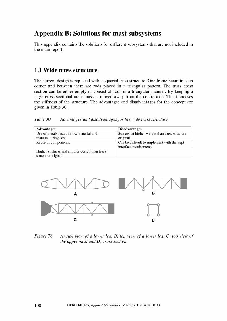
CHALMERS, Applied Mechanics, Master’s Thesis 2010:33 100
Appendix B: Solutions for mast subsystems
This appendix contains the solutions for different subsystems that are not included in the main report.
1.1 Wide truss structure
The current design is replaced with a squared truss structure. One frame beam in each corner and between them are rods placed in a triangular pattern. The truss cross section can be either empty or consist of rods in a triangular manner. By keeping a large cross-sectional area, mass is moved away from the centre axis. This increases the stiffness of the structure. The advantages and disadvantages for the concept are given in Table 30.
Table 30 Advantages and disadvantages for the wide truss structure.
Advantages Disadvantages
Use of metals result in low material and manufacturing cost.
Somewhat higher weight than truss structure original.
Reuse of components. Can be difficult to implement with the kept interface requirement.
Higher stiffness and simpler design than truss structure original.
Figure 76 A) side view of a lower leg, B) top view of a lower leg, C) top view of
the upper mast and D) cross section.
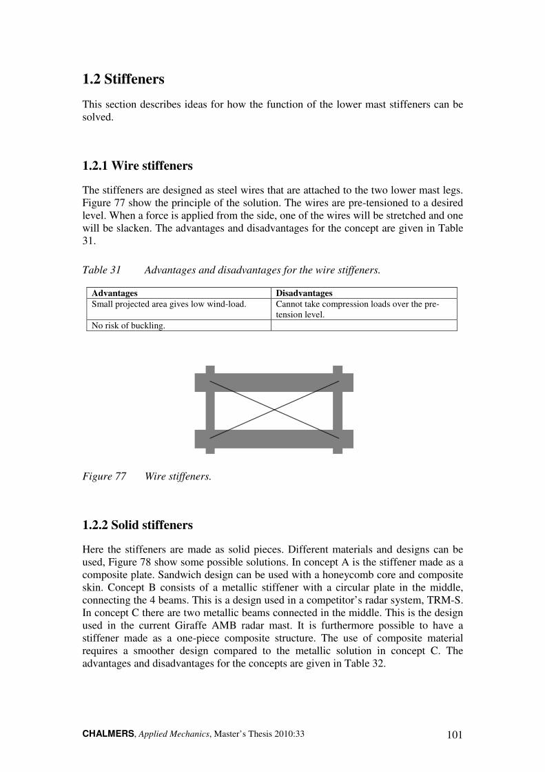
CHALMERS, Applied Mechanics, Master’s Thesis 2010:33 101
1.2 Stiffeners
This section describes ideas for how the function of the lower mast stiffeners can be solved.
1.2.1 Wire stiffeners
The stiffeners are designed as steel wires that are attached to the two lower mast legs. Figure 77 show the principle of the solution. The wires are pre-tensioned to a desired level. When a force is applied from the side, one of the wires will be stretched and one will be slacken. The advantages and disadvantages for the concept are given in Table 31.
Table 31 Advantages and disadvantages for the wire stiffeners.
Advantages Disadvantages
Small projected area gives low wind-load. Cannot take compression loads over the pre-tension level.
No risk of buckling.
Figure 77 Wire stiffeners.
1.2.2 Solid stiffeners
Here the stiffeners are made as solid pieces. Different materials and designs can be used, Figure 78 show some possible solutions. In concept A is the stiffener made as a composite plate. Sandwich design can be used with a honeycomb core and composite skin. Concept B consists of a metallic stiffener with a circular plate in the middle, connecting the 4 beams. This is a design used in a competitor’s radar system, TRM-S. In concept C there are two metallic beams connected in the middle. This is the design used in the current Giraffe AMB radar mast. It is furthermore possible to have a stiffener made as a one-piece composite structure. The use of composite material requires a smoother design compared to the metallic solution in concept C. The advantages and disadvantages for the concepts are given in Table 32.

CHALMERS, Applied Mechanics, Master’s Thesis 2010:33 102
Table 32 Advantages and disadvantages for the solid stiffeners.
Advantages Disadvantages
Concept A
Strong stiffener. Increased weight and wind load.
Simple geometry, suitable for composites.
Concept B Circular plate avoids a weak junction point. More complex design.
Concept C
Re-use of current system. Risk of buckling.
Concept D
Light and strong since composite material is used.
More complex to manufacture. Vacuum moulding is required.
Figure 78 Concept A) plate stiffener, concept B) beams with circle, concept C)
cross stiffener and concept D) composite stiffener.
The attachment of the stiffener to the mast legs can be done in different ways. In Figure 79 the stiffener is attached to a mast with square cross-section and rounded corners. Attachment of the stiffeners to a round cross section will be more difficult. In concept A is the stiffener attached to the bottom of the mast legs. This the way the stiffeners are attached in the current mast. If metallic materials are used, the stiffeners can be attached by welding, bolting or riveting. Composite stiffeners are preferable attached by adhesives. The stiffeners can furthermore be attached on the sides of the two mast legs, concept B. The stiffeners cannot be attached too close to the midpoint since space must be left for the upper mast to be folded in-between the lower mast legs.
Figure 79 Concept A) Stiffener attached at the bottom of the mast legs, concept B)
Stiffener is attached on the side of the mast legs.

CHALMERS, Applied Mechanics, Master’s Thesis 2010:33 103
1.3 Waveguide and cables
For the waveguide and cables, two principal solutions are available. They can be drawn inside the mast our outside the mast.
1.3.1 Inside the mast
The current solution is to draw the cables inside the mast. For mounting and service, this solution requires that inspection hatches are installed on the mast. The hatches will be weak spots on the mast, especially it’s made from composite material.
1.3.2 Outside the mast
The cables and waveguide can also be drawn outside the mast. The benefit with this solution is that it gives easy access for installation and service, no service hatches are necessary. This solution may require that the cables and waveguide are drawn inside a shield like an aluminum profile.
1.4 Locking devices
Solutions for locking the mast to the shelter have been developed. The focus has been on the front locking device, since the design today has a major drawback. Locking of the lower mast to the shelter is currently done by locking the knee joint. If an attempt is made to deploy the upper mast with the front lock activated, the lever arm of the lock will be very small compared to that of the upper hydraulic cylinders. Hence, the lock will fail if this happens.
However these solutions are not implemented in the lightweight mast, but can be used as ideas for further development.
1.4.1 Magnet locks
The mast is locked to the shelter using electromagnets, placed on the mast and on the shelter. This solution does not require moving parts. The strength of the magnet can be customized so that failure of the mast is avoided if an attempt is made to deploy the mast without disabling the locks. A drawback is that an external power source is required and that the strength of magnetic field decreases rapidly with increased distance. If for instance ice comes between the magnets, the strength of the lock is considerably lowered.

CHALMERS, Applied Mechanics, Master’s Thesis 2010:33 104
1.4.2 Hydraulic locks
The front locking device is redesigned to operate similar to the rear locking device. The upper part (Figure 80) is placed on the plate below the knee joint, see Figure 81. With this design, the locking of the lower mast will no longer be by locking the knee joint. Locking of the lower mast is done by pushing a hydraulic rod into the hole in the upper part. The lower locking device has to be lowered, but the same mechanism can be used. By this design the risk of lock failure is reduced.
Figure 80 Lock upper part.
Figure 81 Place for lock.

CHALMERS, Applied Mechanics, Master’s Thesis 2010:33 105
Appendix C: Pugh Selection Matrix
Table 33 Pugh selection matrix.
Reference - Concept 4 Concept 2 Concept 3 Concept 5 Concept 6 Concept 7
Criterion Req/Dp
1.3 High weight reduction Dp 0 -1 1 1 1 1
1.4 Low projected area Dp 0 1 -1 -1 -1 1
1.5 Low complexity Dp 0 1 0 0 0 -1
4.2 High natural frequency Dp 0 -1 1 1 1 1
4.4 High strength margin Dp 0 -1 0 1 0 0
4.5 High buckling resistance Req 0 0 1 1 1 1
5.2 High toughness Dp 0 1 0 -1 0 0
6.3 Low cost Dp 0 1 -1 -1 1 -1
Net value 0 1 1 1 3 2
Rank 4 3 3 3 1 2