design of a casing for a microfluidic device - tu/e · 1. design the design of the casing is made...
TRANSCRIPT

Design of a casing for a microfluidic device
T.J.J.M. Schenkels
August 2011
MT 11.32

Introduction Downscaling multifunctional laboratory systems is an easy recognized trend in biological assays and chemical analyses and we find the most important applications in life sciences, where they replace conventional laboratories. Driving force for shifting from the macro to the micro scale is a decrease in the use of device‐ and sample materials, an increase in the speed of analyses, and a decrease in costs of such testing. The technology frequently used in fabricating microfluidic devices is silicon based, but the time span from design to realization is in the order of a month or more. Reason is that, using silicon or glass, it is difficult to fabricate and integrate flexible parts like pumps, valves, and sometimes even channels. Because of these problems new technologies are being developed and one of them is the recently finished microfluidic device [1]. This product is being tested at the moment and to this end a casing is needed. A casing will be designed that has functionality that complements the already existing microfluidic device. It will therefore need a quick way to connect and disconnect pneumatic tubing that can control the multiple integrated flexible parts as pumps, valves and mixers. The casing also has the goal of compressing and thereby closing the multiple reactor parts. The different parts of the reactor consist of rigid plates with flexible active parts that need to be compressed to seal off all the functional parts. Compressing the multiple reactor parts will be an integral function of the casing to which end a connection mechanism is designed that is able to compress the parts and keep them compressed for a long time. The casing that will be designed needs to have this functionality and needs to be easily adjustable and to be produced at low cost.

ContentsIntroduction ............................................................................................................................................. 2
1. Design .............................................................................................................................................. 4
1.1 The process of the design ........................................................................................................ 4
1.2 Overview .................................................................................................................................. 6
1.3 Details ...................................................................................................................................... 7
2. Analysis ............................................................................................................................................ 9
2.1 Analytical analysis .................................................................................................................... 9
2.2 FEM analysis ............................................................................................................................ 9
2.3 Time to failure ....................................................................................................................... 11
2.4 Moldflow ............................................................................................................................... 12
3. Mould Design ................................................................................................................................ 14
3.1 Partinglines .................................................................................................................................. 14
3.2 Runners ........................................................................................................................................ 14
4. Conclusion and recommendations ................................................................................................ 18
Appendix A: Literature list ............................................................................................................. 19

1. Design The design of the casing is made taking in consideration a couple of boundary conditions. First of all the original microfluidic reactor has to fit inside the casing. Therefore all the edges of the casing will be designed 0.5 mm larger than the reactor itself. Second there is the force that is needed to close the multiple parts together. The force that is needed will be calculated in chapter 2. To deliver this force a connection mechanism needs to be designed. This mechanism needs to consist of one piece and needs to be integrated in the design. The casing should be designed in a way that two of the same parts combined will make a complete casing. The last condition is the total volume of the casing. The casing will be injection moulded on a Ferromatik Milacron K‐TEC 60. This particular machine has a horizontal plunger with a maximum shot volume of 135cc and a vertical plunger with a maximum shot volume of 50cc [2]. The total volume of the casing therefore has to be less than 185cc. Ideally the volume should be less than 135cc since only the horizontal plunger will then be needed.
1.1 TheprocessofthedesignThe basic design of the casing is largely fixed by the shape of the micro fluidic reactor that has to fit in the casing. This means that the casing will have a curved shape with possibilities to attach pneumatic tubing and a fluid inlet and outlet. The total casing will consist of two parts that have to be connected together with some sort of mechanism. The design of this mechanism is a process that started at a steel clip that is often seen on toolboxes and can be seen in figure 1.
Figure 1: A clip as often seen on toolboxes that inspired the design of the connection mechanism. This mechanism is transformed to a design in polymer that consists of only one part. This resulted in the design that can be seen in figure 2.

Figure 2: The first sketch of a connection mechanism. Part a is the flexible part which will be loaded with a compressive stress when the mechanism is in its closed position. Part b is the rigid part which will be loaded with a tensile stress in the closed state. This design is not perfect since the flexible rod is loaded with a compressive stress. This means that the maximum stress cannot be too large since buckling will occur. The design is therefore adapted to a design in which the flexible rods are no longer loaded with a compressive stress but with a tensile stress. Buckling is now no longer a risk and the maximum stress is much larger. The final design can be seen in figure 3.
Figure 3: the clip with (a) the rods, (b) the beam and (c) the cantilever. The clip is made of two ‘rods’ (part a in figure 3) that are 1mm thick and therefore very flexible and a cantilever (part c in figure 3) that will connect to a hook. The rods are connected to a beam with holes (part b in figure 3). The holes are there to make the mechanism lighter and mouldable. The cantilever is tapered to make it stiff on the lower side but thin on the upper side for easy connection.

Figure 4: The hook to which the clip will attach with the rounded inside in detail. The hook is a simple beam with a curved inside that has a radius that is slightly larger than the radius of the cantilevers edge (figure 4). The cantilever will therefore slide into the hook and lock in place. Since the two parts of the casing are mirrored there will be six connection points around the final reactor. This should be enough to apply the force needed to seal the fluid channels. This is also tested in a FEM analysis in chapter 2.
1.2 OverviewThe final design of the casing can be seen in figure 5. The left image is an exploded view of the total composition with the casing and the microfluidic reactor. Parts a and f are the casing and the other parts form the reactor. On the right a closed view of the assembled casing can be seen. The curvature of the casing is almost the same as the curvature of the reactor. The small difference is due to the length of the clips that are used to close the casing. To make the casing compress all the parts of the reactor firmly there are multiple points where the casing touches to the reactor.
Figure 5: The left image is an exploded view of the casing with the reactor. On the right the closed casing.

These points can be seen in figure 6. The beams in the middle and all the cylinders are pressed against the reactor. These same parts will be mirrored when two casing parts are combined and the reactor is between them. As a result the pressure that is needed for compressing the parts together is evenly distributed over the entire surface of the microfluidic reactor.
Figure 6: inside view of the casing
1.3 DetailsThe casing consists of a shell and some details for functionality. First of all there is the connection for the pneumatic tubing. This connection is made by putting the tube in a tapered hole as seen in figure 7 (part a).
Figure 7: Cross‐section of the pneumatic connection with (a) the tapered hole for the connection of the pneumatic tubes and (b) the tapered hole pressed against the microfluidic reactor. The tubes will stay in place since the radius of the hole is a little smaller than the radius of the tube. The tubes are now connected to the cylinders that are on the bottom placed against the reactor. This again is done by a tapered part to make the placing of the casing against the reactor easier. This part is indicated with (b) in figure 7. The cylinders itself are tapered on the inside and the outside to prevent shrinking on the mould.

The next important detail is a practical one. The reactor will be covered entirely by the casing. This means that the reservoir that is implemented in the reactor design will not be visible anymore. It is important that the reservoir is visible to check if the reactor is filled or not. To make the reservoir visible a small window is made in the casing as seen in figure 8.
Figure 8: window for reservoir visibility with (a) the casing and (b) the microfluidic reactor

2. Analysis
2.1 AnalyticalanalysisThe connection between the two parts has to be strong enough not to break at working conditions. Denteneer [3] found that in a worst case scenario the distributed pressure from the fluid in the reactor is 5.5 kPa. The forces needed to deform the channel walls are negligible. To make sure the forces applied by the connection mechanism are sufficient, the distributed pressure used for calculation is increased to 10 kPa which results in a total force of 136 N. The dimensions of the design are checked by calculating the elongation of each of the connecting rods.
0.003
Since the elongation at break for polycarbonate is approximately 5% the mechanism should be able to close the two parts of the casing together.
2.2 FEManalysisTo see if the analytical analysis is usable a FEM analysis is performed in MARC/Mentat. To this end a model of the clip is drawn as seen in figure 9.
Figure 9: the clip and the mesh as used in MARC/Mentat in the undeformed situation. To analyze the strain in the clip a force is applied on the top surface of the beam. This force bends the clip until it reaches a stop surface that acts as the hook in the real product. This can be seen in figure 10.

Figure 10: The deformed situation of the clip in Marc/Mentat. The strain distribution in the part is then plotted to see what the maximum strain was and where it would occur.
Figure 11: the strain distribution on the bottom side of the clip.This is where the maximum strain occurs The distribution of the strain on the bottom side (figure 11) of the clip is now analyzed. The maximum strain that occurs is approximately 3%. This is a factor ten higher than predicted in the analytical analysis but still below the elongation at break for polycarbonate. This large difference in strain can be explained by the bending of the rods. In the analytical analysis only the strain due to the force of the fluid in the reactor is taken into account. In the FEM analysis though, also the strain due to the bending of the rods is taken into account. This bending can also be analyzed analytically.

Figure 12: quarter of circle The difference in length between edge 1 of the quarter of a cylinder as drawn in figure 12 and its centerline can be calculated using the circumference of a circle. The strain at bending the quarter cylinder to a straight rod can be calculated by dividing these two and this gives the following expression:
11
For a diameter of the circle of 40 mm (the size used in the clip) this gives us a strain of 2.5% with the strain of the force acting on the rods taken into account it gives a strain of 2.8% which is almost the same as the strain in the FEM analysis which is 2.9%.
2.3 TimetofailureThe long term failure of polycarbonate can be predicted with an Eyring flow process. This is already done by Klompen et al. [4] and the result can be seen in figure 13. The stress in the rods will be approximately 48 MPa at a strain of 3% as seen in figure 13. The results from Klompen et al. show that for this stress the time to failure will be in the order of 10 s which is approximately 320 years.
Figure 13: Stress‐strain curve for polycarbonate on the left and on the right the time to failure for uniaxial extension (cirles) which is a simplified model for the rods in the clip.

2.4 MoldflowSince there are a lot of details in the design of the casing a moldflow simulation is performed to make sure the casing is mouldable and to get an indication of the position of the weldlines. In figure 14 it can be seen that the entire part is filled after 1.2 seconds. It can also be seen that there are weldlines situated on the edges of the clips. The weldlines can be guided depending on the runner design that is used. When the injection points on the clips start injecting first and the rest of the injection points a little later, the weldlines will not be on the edge of the clips but somewhere on top of the casing. This difference in timing can be done in different ways. It is possible to use different lengths of runners for different injection points which has influence on the injection timing. This solution needs a very delicate way of designing the runner and is therefore less suitable. A method that is particularly fit for the Ferromatik Milacron K‐TEC 60 is using both plungers. The vertical plunger can be used to inject clips and start first. After some time the horizontal plunger will start injecting the rest of the injectionpoints. The time difference between the two plungers can be controlled very precise.

Figure 14: results of the moldflow simulation. The thick black lines in the last image represent the
weldlines.

3. MouldDesign
3.1PartinglinesThe moulding of the product is for a large part straightforward. There are some difficult places in the
mould where the partinglines have to be designed correctly. the clip consists of the rods and the
cantilever and the partinglines will be different on those two parts. To illustrate this two section
views are made and can be seen in figure 15.
Figure 15: section views of the clip with the partinglines of the mould in place.
The same problem occurs at the hook to which the clip is attached. There is a different partingline
here either and the solution to this is made clear in figure 16.
Figure 16: section view of the hook with the parting line.
3.2RunnersAs seen in the former chapter, the design is mouldable although some assumptions have been made.
First there is the assumption that there are 7 injection points. This is only possible when both
plungers on the Ferromatik Milacron K‐TEC 60 are used. The horizontal plunger will inject directly on
the injection point on top of the casing (injection point 7 in figure 17). The vertical plunger will be
used to inject the clips (injection point 1 to 6 in figure 17).

Figure 17: An overview of the positioning of the runners. The runners 1 to 6 are injected by the
vertical plunger and runner 7 is injected by the horizontal plunger.
The next assumption that is made, already mentioned in the former chapter, is the timing of the flow
in the multiple injection points. Injection points 1 to 6 have to start at the same time. This causes
some problems in the runner design. The runners to the different injection points have to be of equal
length, or more accurately of ‘equal time’. To reach this goal multiple possible designs are presented
here. Injection point 7 is not in these designs since it has a runner directly from the plunger to the
injection point.
Figure 18: The runner design where the difference in length is solved by an extra long runner.

The most obvious way to solve this problem is by making runners of equal length. This means that
the runners that go to injection points 3 and 4 and to injection points 5 and 6 are symmetric and
therefore of equal length and an extra long path is used to create the runner to injection points 1 and
2. This can be seen in figure 18.
Figure 19: The runner design where the difference in length is solved by a difference in channel width.
Less obvious but as effective as the first solution is using the width of the runner channels to time the
flows. A wider channel has a faster flow and can therefore be used as seen in figure 19. Injection
points 4 and 5 are now connected to a wide runner where the injection points 1,2,3 and 6 are
connected to a thinner runner. The difference in length is now cancelled out by the difference in flow
velocity.
Solutions one and two are both very effective but they need very long runners. This might cause
problems since the shot volume of the vertical plunger of the Ferromatik Milacron K‐TEC 60 is only
about 50cc.
To make the runners smaller a three plate mould design is considered. This means that one parting
surface of the mould can be used for the product and the other parting surface for the runners. The
runners can now be on top of the product and therefore need less length to reach the injection
points. This makes the design of the runner fairly easy since all injection points are positioned
symmetrical around the centerline as shown in figure 20 This design has the advantage that only the
horizontal plunger is needed to inject at all seven injection points.
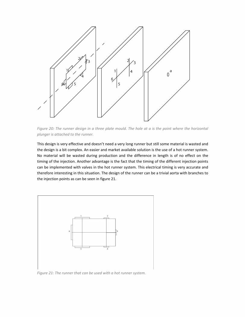
Figure 20: The runner design in a three plate mould. The hole at a is the point where the horizontal
plunger is attached to the runner.
This design is very effective and doesn’t need a very long runner but still some material is wasted and
the design is a bit complex. An easier and market available solution is the use of a hot runner system.
No material will be wasted during production and the difference in length is of no effect on the
timing of the injection. Another advantage is the fact that the timing of the different injection points
can be implemented with valves in the hot runner system. This electrical timing is very accurate and
therefore interesting in this situation. The design of the runner can be a trivial aorta with branches to
the injection points as can be seen in figure 21.
Figure 21: The runner that can be used with a hot runner system.

4. Conclusionandrecommendations To attach a microfluidic device to its pneumatic tubing and to compress the multiple parts of the device a casing is designed. This casing is easy to use, make and replace. There are options to connect the pneumatic tubing, there is an intake and outlet for the fluids and a window to see te reservoir in the reactor. To connect the two parts of the casing a mechanism is designed consisting of a clip and a hook. This clip is analysed and it is usable for a long period of time. There are on the other hand some difficulties. The strain in the connection rods is high, though still usable. This could be reduced by increasing the radius of the rods. There will be an optimal radius at which the strain will be less high and the clip is still easy to connect to the hook. The next difficulty is the mouldability. As can be seen in the moldflow analysis, a lot of injection points are needed. Therefore a long runner will be needed and the total volume of the casing is already 110cc. This means that there is only a total of 25cc left to realize a runner along the entire casing when only the horizontal plunger is used. The last problem is the timing during moulding. The top gate should be delayed a little to make sure the clips are completely filled and the weldlines will be situated at the top of the casing and the clips will be connected firmly to the casing. Some solutions to these problems are presented but not investigated thoroughly. Therefore further optimization can be done.

AppendixA: Literaturelist
1. A full‐polymeric mouldable microfluidic device part 1: The process of design. P.E. Neerincx, R.P.J. Denteneer, H.E.H. Meijer. Macromolecular Materials and Engineering, doi: 10.1002/mame.201100047
2. http://www.ferromatik.com/de/information/download/Technische_Daten_Deutsch_Englisch_2009.pdf
3. Design and Realization of a Full‐Polymeric Injection Mouldable Multifunctional Microfluidic Reactor. Denteneer, R.P.J. s.l: Eindhoven University of Technology, 2009. Master’s Thesis.
4. Quantitative Prediction of Long‐Term Failure of Polycarbonate. E. T. J. Klompen, T. A. P. Engels, L. C. A. van Breemen, P. J. G. Schreurs, L. E. Govaert,* and H.E.H. Meijer. Macromolecules 2005, 38, 7009‐7017.