design of a 20,000 pound variable stiffness actuator for...
TRANSCRIPT
Design of a 20,000 Pound Variable Stiffness Actuator
for Structural Vibration Attenuation
John Leavitt, James E. Bobrow, Faryar Jabbari,
Department of Mechanical and Aerospace Engineering
University of California, Irvine
Irvine, CA 92697
{jebobrow, fjabbari}@uci.edu
October 1, 2007
Abstract
This paper describes the design of a novel actuator capable of protecting afull scale structure from severe load conditions. The design includes a cylinderfilled with pressurized nitrogen and uses commercially available components.We demonstrate that the actuator behaves like a spring with an adjustableunstretched length, and that the effective spring stiffness can be changed eas-ily by changing the initial cylinder pressure. In order to test the actuatoron a full scale structure, an effective spring constant of approximately 10,000pounds/inch was required over a two inch stroke. Because of the spring-like be-havior, rather than damper-like behavior, the actuator does not transmit highforces to a vibrating structure like linear viscous dampers do when velocitiesare high. We analyze features of critical importance to the design of the actu-ator such as the cylinder dimensions, operating pressure, and valve selection.We then investigate the performance using a novel experimental apparatus thatmimics the dynamics of a single story building, but has 1/400 the weight.
1 Introduction
Actuators that are capable of protecting structures from severe load conditions are
important for many applications. Typical applications include the reduction of
building structural failures during earthquake and wind loading, and the isolation
of human passengers and precision components in vehicles that move over rough
terrain. An approach often used to achieve this protection is the incorporation of
a passive damper as an integral part of the isolation system. In many instances
this approach is warranted, but for some load conditions, dampers can make the
problem worse. For instance, for low amplitude, high frequency excitations, linear
1
viscous dampers amplify the force transmitted to a structure since the force from a
damper is velocity-dependent rather than position-dependent, and velocity increases
linearly with frequency. One method to reduce the force transmission is to use a
power-law damper, where the output force can be approximated by f = cvp with
0 < p < 1 [23, 18]. This power-law damper effectively limits the force transmitted
to the structure when velocities are high.
As an alternative to power-law dampers, in this work we describe the mechanical
and electrical design of an actuator capable of isolating a structure from high velocity
loading or from motions with high frequency content. It uses a different method
for extracting energy from the moving structure than viscous dampers do. The
actuator is designed to have a 20,000 pound peak output force capability, so it has
the potential to be used to protect full-scale structures. The specifications used
here are derived from a set of actuators developed for full-scale testing on a research
structure at the National Center for Research on Earthquake Engineering (NCREE)
in Taipei, Taiwan, see [25]. We also describe a unique one-degree-of-freedom test
apparatus used for performance testing of the hardware. The test apparatus behaves
like a single story building, but it weighs much less, and allows us to conduct full-
scale experiments without a full-scale building.
The device developed in this work behaves like a controlled spring rather than a
damper, so it does not transmit forces to a structure when velocities are high. The
actuator is called a “semi-active” device, which is one that uses sensors and control
logic to produce its output force, but requires little power consumption to do so
and can never add energy to the vibrating structure. In our approach, the actuator
behaves like a linear spring. However, at appropriate times, the effective unstretched
length of the actuator is changed–or reset–to extract energy from the vibrating
structure. The concept of stiffness elements that are reset to zero for extraction
of energy was also used in [14, 3], in which a modal approach was used to study
and design control laws for piezoelectric or piezoceramic devices with typical output
levels considerably lower than our aim here. Analytical details of our approach have
been presented in [1, 8, 24], where it was shown that the settling time for transient
response is faster for the variable stiffness approach presented here than for linear
2
viscous dampers, and that the approach performs well for general structures with
many modes of vibration. The design aspects developed in this work for a reset-able
actuator capable of producing large output forces has not been published previously.
A comparison of other variable stiffness dampers has been conducted by Dja-
jakesukma et. al [5] for buildings subject to different earthquake loadings. The
testing of variable stiffness control algorithms on full-scale buildings has been con-
ducted in [10, 13]. The actuators used for these structures have high output force
levels and can be expensive to make. A switched stiffness approach based on a
velocity estimator has been conducted in [17]. There are only a few completely
passive dampers with the high output force levels needed for structural vibration
suppression commercially available today [22]. Semi-active control systems based on
variable damping mechanisms have been the subject of much research over recent
years. For instance, Jalili [9] analyzes and reviews various control system strategies
using electro-rheological (ER) and magneto-rheological (MR) fluid dampers. Dyke,
et. al [6, 16], have proposed a clipped optimal H2/LQG controller that outputs zero
force when the device rod motion does not oppose the desired force. Ahmadian [19]
has used an MR damper to investigate the so-called “sky-hook” control algorithm
to providing passenger comfort in truck seat suspensions. One alternative to devices
with variable damping or variable stiffness is a friction-based damper. These devices
usually have two or more sliding surfaces in contact with another, which are pressed
to together with some form of clamping mechanism [12, 7]. Their advantages include
zero fluid leakage, durable parts, and an insensitivity to temperature.
The results presented in this work are focused on the design of the actuator. In
addition to the test results presented here, the desirable performance of the device
was also evaluated in [25] and [11], via experiments and simulations, respectively.
One of the key features of the proposed design is the reliance on standard, off-the-
shelf components and materials to obtain high resisting forces. In this paper, we
analyze features of importance to the design of the actuator so that one can choose
the critical dimensions to achieve any stiffness and stroke. These include the cylinder
dimensions, operating pressure, and valve selection.
3
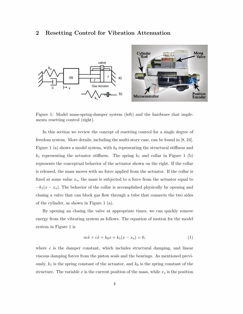
2 Resetting Control for Vibration Attenuation
valve
m
Gas Actuatorx
1 a)
c
k0
b)k1
2
Figure 1: Model mass-spring-damper system (left) and the hardware that imple-ments resetting control (right).
In this section we review the concept of resetting control for a single degree of
freedom system. More details, including the multi-story case, can be found in [8, 24].
Figure 1 (a) shows a model system, with k0 representing the structural stiffness and
k1 representing the actuator stiffness. The spring k1 and collar in Figure 1 (b)
represents the conceptual behavior of the actuator shown on the right. If the collar
is released, the mass moves with no force applied from the actuator. If the collar is
fixed at some value xs, the mass is subjected to a force from the actuator equal to
−k1(x − xs). The behavior of the collar is accomplished physically by opening and
closing a valve that can block gas flow through a tube that connects the two sides
of the cylinder, as shown in Figure 1 (a).
By opening an closing the valve at appropriate times, we can quickly remove
energy from the vibrating system as follows. The equation of motion for the model
system in Figure 1 is
mx + cx + k0x + k1(x − xs) = 0, (1)
where c is the damper constant, which includes structural damping, and linear
viscous damping forces from the piston seals and the bearings. As mentioned previ-
ously, k1 is the spring constant of the actuator, and k0 is the spring constant of the
structure. The variable x is the current position of the mass, while xs is the position
4
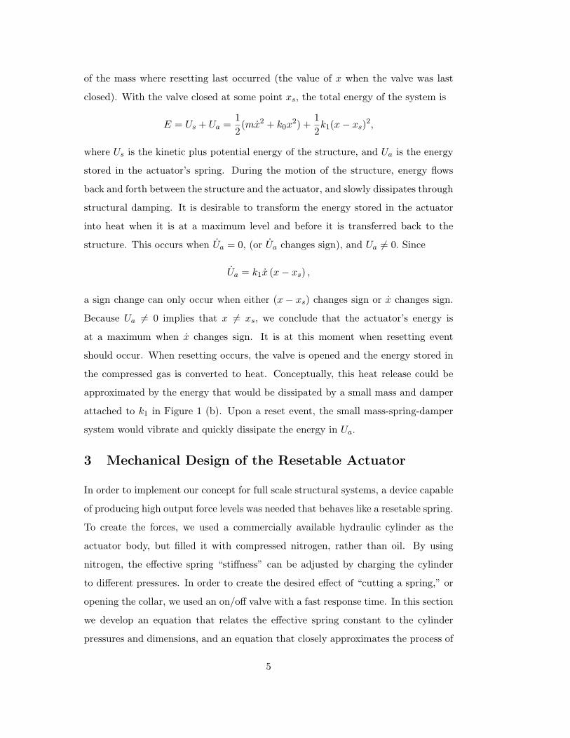
of the mass where resetting last occurred (the value of x when the valve was last
closed). With the valve closed at some point xs, the total energy of the system is
E = Us + Ua =1
2(mx2 + k0x
2) +1
2k1(x − xs)
2,
where Us is the kinetic plus potential energy of the structure, and Ua is the energy
stored in the actuator’s spring. During the motion of the structure, energy flows
back and forth between the structure and the actuator, and slowly dissipates through
structural damping. It is desirable to transform the energy stored in the actuator
into heat when it is at a maximum level and before it is transferred back to the
structure. This occurs when Ua = 0, (or Ua changes sign), and Ua 6= 0. Since
Ua = k1x (x − xs) ,
a sign change can only occur when either (x − xs) changes sign or x changes sign.
Because Ua 6= 0 implies that x 6= xs, we conclude that the actuator’s energy is
at a maximum when x changes sign. It is at this moment when resetting event
should occur. When resetting occurs, the valve is opened and the energy stored in
the compressed gas is converted to heat. Conceptually, this heat release could be
approximated by the energy that would be dissipated by a small mass and damper
attached to k1 in Figure 1 (b). Upon a reset event, the small mass-spring-damper
system would vibrate and quickly dissipate the energy in Ua.
3 Mechanical Design of the Resetable Actuator
In order to implement our concept for full scale structural systems, a device capable
of producing high output force levels was needed that behaves like a resetable spring.
To create the forces, we used a commercially available hydraulic cylinder as the
actuator body, but filled it with compressed nitrogen, rather than oil. By using
nitrogen, the effective spring “stiffness” can be adjusted by charging the cylinder
to different pressures. In order to create the desired effect of “cutting a spring,” or
opening the collar, we used an on/off valve with a fast response time. In this section
we develop an equation that relates the effective spring constant to the cylinder
pressures and dimensions, and an equation that closely approximates the process of
5
gas pressure equalization that occurs after the valve has been opened. This latter
equation has not been presented previously, and is important because it can be used
to choose the dimensions of the valve that controls the gas flow. Finally, we briefly
discuss some of the design considerations encountered during the implementation of
our control logic on a low-cost microcontroller.
3.1 Spring-like behavior of the system
x
V1V
2
F
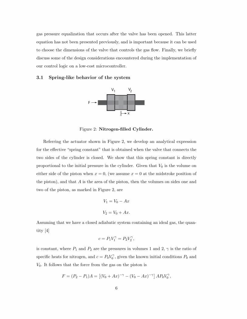
Figure 2: Nitrogen-filled Cylinder.
Referring the actuator shown in Figure 2, we develop an analytical expression
for the effective “spring constant” that is obtained when the valve that connects the
two sides of the cylinder is closed. We show that this spring constant is directly
proportional to the initial pressure in the cylinder. Given that V0 is the volume on
either side of the piston when x = 0, (we assume x = 0 at the midstroke position of
the piston), and that A is the area of the piston, then the volumes on sides one and
two of the piston, as marked in Figure 2, are
V1 = V0 − Ax
V2 = V0 + Ax.
Assuming that we have a closed adiabatic system containing an ideal gas, the quan-
tity [4]
c = P1Vγ1 = P2V
γ2 ,
is constant, where P1 and P2 are the pressures in volumes 1 and 2, γ is the ratio of
specific heats for nitrogen, and c = P0Vγ0 , given the known initial conditions P0 and
V0. It follows that the force from the gas on the piston is
F = (P2 − P1)A =[
(V0 + Ax)−γ − (V0 − Ax)−γ]
AP0Vγ0 ,
6

as a function of x. For motion of the piston near x = 0, F (x) can be approximated
by
F (x) ∼=dF (0)
dxx = −
2A2γP0
V0x. (2)
Viewing the cylinder as a spring, from (2) the spring constant is
k =2A2γP0
V0. (3)
Note that k is directly proportional to P0, the pressure that the cylinder is initially
charged to. Equation (3) is used to choose the cylinder dimensions (bore and stroke)
and operating pressure P0 in order to achieve a given stiffness k. This can be done
for a given maximum cylinder operating pressure as defined by the manufacturer
as follows. For a given maximum cylinder pressure Pmax, desired stiffness k, and
maximum piston travel xmax, we have F = kxmax = PmaxA, which gives the area
A, and hence the cylinder bore. Once the bore has been chosen, the stroke must be
longer than 2xmax (the cylinder moves a total distance of ±xmax), and this choice
defines V0. Once V0 is known, P0 can be chosen to give the desired value of k. In
our case, xmax was 1.0 inches, k was 10,000 lb/inch, and pmax was 3000 psi. This
led to the selection of a cylinder bore of 4.0 inches, a stroke of 3.0 inches, with an
operating pressure P0 of about 700 psi.
We tested the stiffness relationship at various initial cylinder pressures, while
keeping the control valve closed. Oscillating the pendulum shown in the next section
by hand, we recorded the rod position and the pressure on each side of the actuator as
functions of time. Figure 3 shows data taken from the actuator when it was initially
charge to a pressure of 285 psia, plotted on the left versus time. To test for linearity,
the rod position has been scaled. Note that over the entire motion, the net force
coincides directly with the scaled position, indicating that the linearized analysis is
justified. This linear relationship was seen in all of the tests we performed. Next,
to determine the spring constant of the cylinder, we plotted the net force versus
the rod position, and fit a line to the data. The right-hand plot in Figure 3 shows
the best fit line for the data. The slope of the line is 4390 lbs/in and the value
predicted by (3) was 4432 lbs/in. This value is slightly higher than the measured
spring constant–probably because it is difficult to measure the exact cylinder volume
7
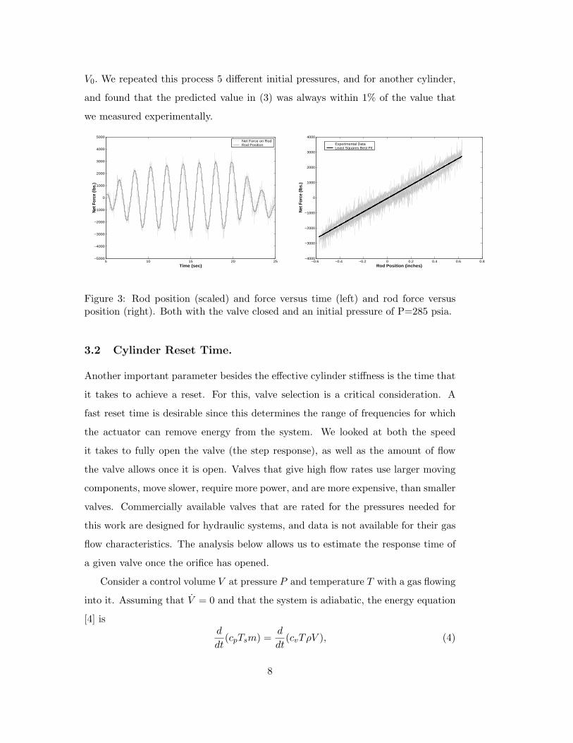
V0. We repeated this process 5 different initial pressures, and for another cylinder,
and found that the predicted value in (3) was always within 1% of the value that
we measured experimentally.
5 10 15 20 25−5000
−4000
−3000
−2000
−1000
0
1000
2000
3000
4000
5000
Time (sec)
Net
For
ce (l
bs.)
Net Force on RodRod Position
−0.6 −0.4 −0.2 0 0.2 0.4 0.6 0.8−4000
−3000
−2000
−1000
0
1000
2000
3000
4000
Rod Position (inches)
Net
For
ce (l
bs.)
Experimental DataLeast Squares Best Fit
Figure 3: Rod position (scaled) and force versus time (left) and rod force versusposition (right). Both with the valve closed and an initial pressure of P=285 psia.
3.2 Cylinder Reset Time.
Another important parameter besides the effective cylinder stiffness is the time that
it takes to achieve a reset. For this, valve selection is a critical consideration. A
fast reset time is desirable since this determines the range of frequencies for which
the actuator can remove energy from the system. We looked at both the speed
it takes to fully open the valve (the step response), as well as the amount of flow
the valve allows once it is open. Valves that give high flow rates use larger moving
components, move slower, require more power, and are more expensive, than smaller
valves. Commercially available valves that are rated for the pressures needed for
this work are designed for hydraulic systems, and data is not available for their gas
flow characteristics. The analysis below allows us to estimate the response time of
a given valve once the orifice has opened.
Consider a control volume V at pressure P and temperature T with a gas flowing
into it. Assuming that V = 0 and that the system is adiabatic, the energy equation
[4] isd
dt(cpTsm) =
d
dt(cvTρV ), (4)
8
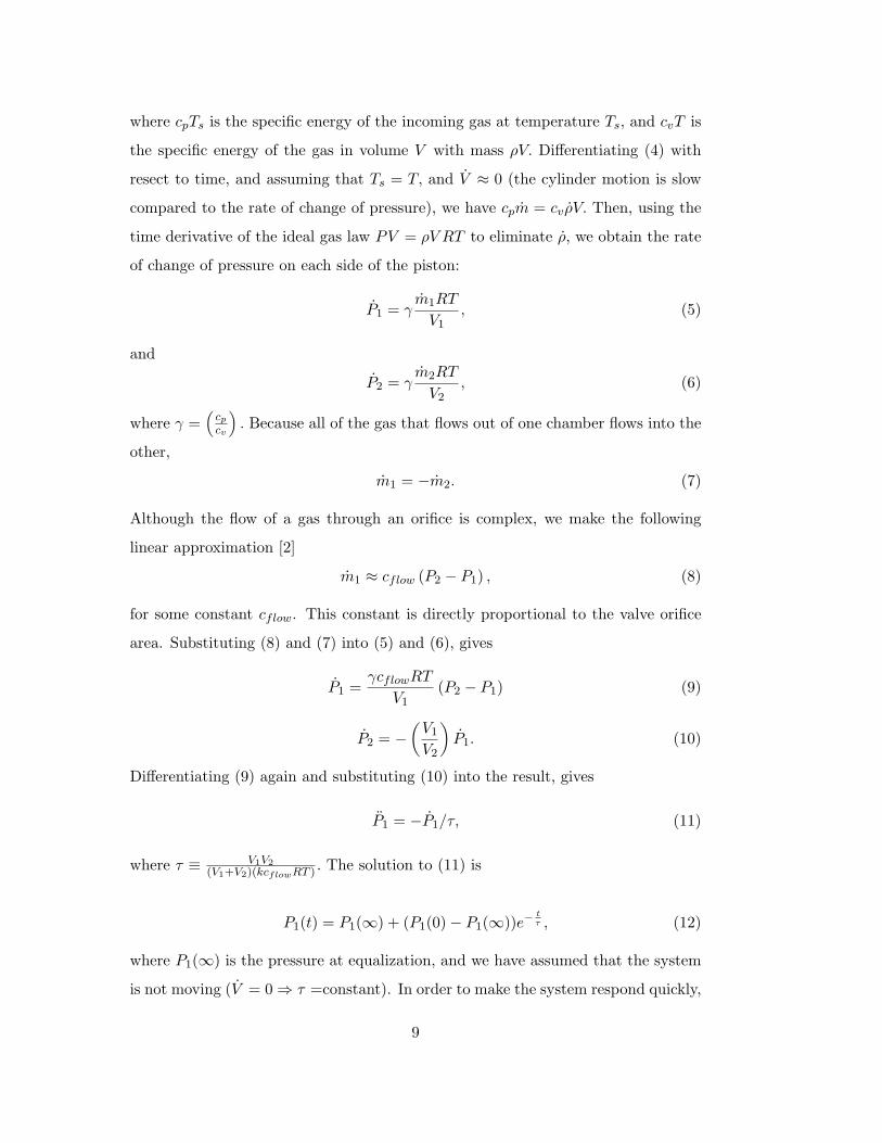
where cpTs is the specific energy of the incoming gas at temperature Ts, and cvT is
the specific energy of the gas in volume V with mass ρV. Differentiating (4) with
resect to time, and assuming that Ts = T, and V ≈ 0 (the cylinder motion is slow
compared to the rate of change of pressure), we have cpm = cvρV. Then, using the
time derivative of the ideal gas law PV = ρV RT to eliminate ρ, we obtain the rate
of change of pressure on each side of the piston:
P1 = γm1RT
V1, (5)
and
P2 = γm2RT
V2, (6)
where γ =(
cp
cv
)
. Because all of the gas that flows out of one chamber flows into the
other,
m1 = −m2. (7)
Although the flow of a gas through an orifice is complex, we make the following
linear approximation [2]
m1 ≈ cflow (P2 − P1) , (8)
for some constant cflow. This constant is directly proportional to the valve orifice
area. Substituting (8) and (7) into (5) and (6), gives
P1 =γcflowRT
V1(P2 − P1) (9)
P2 = −
(
V1
V2
)
P1. (10)
Differentiating (9) again and substituting (10) into the result, gives
P1 = −P1/τ, (11)
where τ ≡ V1V2
(V1+V2)(kcflowRT ) . The solution to (11) is
P1(t) = P1(∞) + (P1(0) − P1(∞))e−tτ , (12)
where P1(∞) is the pressure at equalization, and we have assumed that the system
is not moving (V = 0 ⇒ τ =constant). In order to make the system respond quickly,
9

the time constant τ can be made small by increasing the size of the valve orifice
cflow. Furthermore, τ achieves its minimum value at either end of the piston stroke,
since either V1 or V2 is a minimum at these points. Physically, the net force changes
quickly at these locations because small changes in mass flow have a large influence
on the pressure when the chamber volume is small. The worst case, or slowest value
for the response is at the midstroke position, where τ = V0
2kcflowRT(note at midstroke
V0 = V1 = V2.) From this analysis, we conclude that near the ends of the piston
travel, or for a large valve orifice and tubing, the pressures will equalize relatively
quickly and produce the desired effect of a fast resetting spring.
We tested several commercially available valves, and found the Moog D633 pro-
portional valve gave a fast overall cylinder reset time. This valve uses a single stage
solenoid to drive the internal spool, and thus has a relatively fast step response.
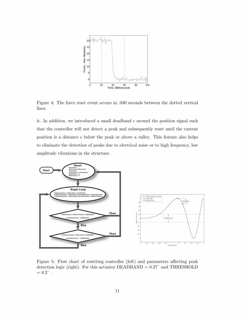
Figure 4 shows one representative result of tests we conducted to determine the
response time of the actuator and valve combination. In this Figure, the net force
on the piston (as measured with pressure transducers on each side) is plotted versus
time. The vertical dotted lines indicate the duration that control signal was sent to
the valve in order to hold it open. One can see from the plot that there is a delay
before the force quickly drops. The initial delay of about .017 seconds is caused
by the step response of the valve itself. The total time for the reset event is less
than .040 seconds. This is consistent with previous results in [1] for a much smaller
device which has a total reset time of approximately .020 seconds. We note that the
time delay and flow constants are not often provided by the manufacturer, so it is
difficult to predict accurately the results shown in Figure 4 without testing.
3.3 Microcontroller Logic
The control logic was implemented on a Rabbit [15] microcontroller, which has
an on-board quadrature decoder and digital outputs. The cylinder rod position
was measured by an optical encoder [21], and the valve was controlled with digital
output signals. The control logic determines the times at which x = 0 by looking
for the peaks or valleys in the piston displacement. At these times the actuator
pressure is released by opening the Moog valve for .040 seconds and then closing
10
0 20 40 60 80 100
0
5
10
15
20
25
30
For
ce,
Kilo
−N
ewto
nsTime, Milliseconds
Figure 4: The force reset event occurs in .040 seconds between the dotted verticallines.
it. In addition, we introduced a small deadband ǫ around the position signal such
that the controller will not detect a peak and subsequently reset until the current
position is a distance ǫ below the peak or above a valley. This feature also helps
to eliminate the detection of peaks due to electrical noise or to high frequency, low
amplitude vibrations in the structure.
Open Valve
Pause for 40 milliseconds
Close Valve
ZeroPosition = GetPosition()
MaxPosition = 0
MinPosition = 0
Reset
RelativePosition = GetPosition() - ZeroPosition
If (RelativePosition > MaxPosition) then MaxPosition = RelativePosition
If (RelativePosition < MinPosition) then MinPosition = RelativePosition
Begin Loop
If (MaxPosition - RelativePosition) > DEADBAND
and (MaxPosition > THRESHOLD)
If (RelativePosition - MinPosition) > DEADBAND
and (MinPosition < -THRESHOLD)
Then
Then
Else
Else
Start
0 0.2 0.4 0.6 0.8 1 1.2 1.4 1.6 1.8 2
1
0.8
0.6
0.4
0.2
0
0.2
0.4
0.6
0.8
1
Time (seconds)
Positio
n (
inches)
Position relative to last reset
Actual Peak
Detected PeakDEADBAND
2 THRESHOLDx
Figure 5: Flow chart of resetting controller (left) and parameters affecting peakdetection logic (right). For this actuator DEADBAND = 0.27¨ and THRESHOLD= 0.2¨ .
11
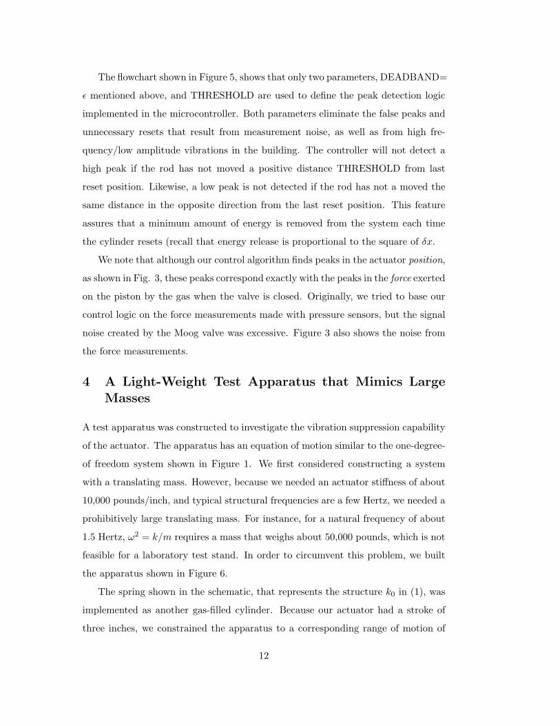
The flowchart shown in Figure 5, shows that only two parameters, DEADBAND=
ǫ mentioned above, and THRESHOLD are used to define the peak detection logic
implemented in the microcontroller. Both parameters eliminate the false peaks and
unnecessary resets that result from measurement noise, as well as from high fre-
quency/low amplitude vibrations in the building. The controller will not detect a
high peak if the rod has not moved a positive distance THRESHOLD from last
reset position. Likewise, a low peak is not detected if the rod has not a moved the
same distance in the opposite direction from the last reset position. This feature
assures that a minimum amount of energy is removed from the system each time
the cylinder resets (recall that energy release is proportional to the square of δx.
We note that although our control algorithm finds peaks in the actuator position,
as shown in Fig. 3, these peaks correspond exactly with the peaks in the force exerted
on the piston by the gas when the valve is closed. Originally, we tried to base our
control logic on the force measurements made with pressure sensors, but the signal
noise created by the Moog valve was excessive. Figure 3 also shows the noise from
the force measurements.
4 A Light-Weight Test Apparatus that Mimics Large
Masses
A test apparatus was constructed to investigate the vibration suppression capability
of the actuator. The apparatus has an equation of motion similar to the one-degree-
of freedom system shown in Figure 1. We first considered constructing a system
with a translating mass. However, because we needed an actuator stiffness of about
10,000 pounds/inch, and typical structural frequencies are a few Hertz, we needed a
prohibitively large translating mass. For instance, for a natural frequency of about
1.5 Hertz, ω2 = k/m requires a mass that weighs about 50,000 pounds, which is not
feasible for a laboratory test stand. In order to circumvent this problem, we built
the apparatus shown in Figure 6.
The spring shown in the schematic, that represents the structure k0 in (1), was
implemented as another gas-filled cylinder. Because our actuator had a stroke of
three inches, we constrained the apparatus to a corresponding range of motion of
12
θ
L
x
F
d
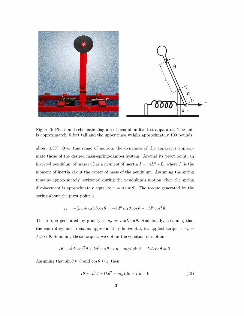
Figure 6: Photo and schematic diagram of pendulum-like test apparatus. The unitis approximately 5 feet tall and the upper mass weighs approximately 100 pounds.
about ±30◦. Over this range of motion, the dynamics of the apparatus approxi-
mate those of the desired mass-spring-damper system. Around its pivot point, an
inverted pendulum of mass m has a moment of inertia I = mL2 + Ic, where Ic is the
moment of inertia about the center of mass of the pendulum. Assuming the spring
remains approximately horizontal during the pendulum’s motion, then the spring
displacement is approximately equal to x = d sin(θ). The torque generated by the
spring about the pivot point is
τs = −(kx + cx)d cos θ = −kd2 sin θ cos θ − cθd2 cos2 θ.
The torque generated by gravity is ug = mgL sin θ. And finally, assuming that
the control cylinder remains approximately horizontal, its applied torque is τc =
Fd cos θ. Summing these torques, we obtain the equation of motion
Iθ + cθd2 cos2 θ + kd2 sin θ cos θ − mgL sin θ − Fd cos θ = 0.
Assuming that sin θ ≈ θ and cos θ ≈ 1, then
Iθ + cd2θ + (kd2 − mgL)θ − Fd = 0 (13)
13
and since x = θd, x = θd, we obtain the linearized differential equation of the
pendulum in terms of x:
mbx + cx + kbx = F (14)
where mb =(
mL2+Ic
d2
)
and kb =(
k − mgLd2
)
. Notice that mb varies directly with L2
and inversely with d2. By making L large and d small, we are able to obtain systems
with effective masses that are much larger than their actual mass m. For the test
apparatus shown, we used L/d = 20, with a pendulum weight of 100 pounds. This
gave weight for mb of about 50,000 pounds as was desired.
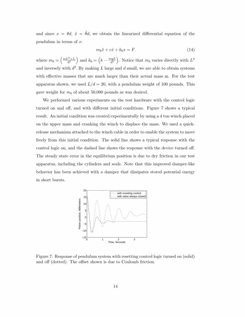
We performed various experiments on the test hardware with the control logic
turned on and off, and with different initial conditions. Figure 7 shows a typical
result. An initial condition was created experimentally by using a 4 ton winch placed
on the upper mass and cranking the winch to displace the mass. We used a quick-
release mechanism attached to the winch cable in order to enable the system to move
freely from this initial condition. The solid line shows a typical response with the
control logic on, and the dashed line shows the response with the device turned off.
The steady state error in the equilibrium position is due to dry friction in our test
apparatus, including the cylinders and seals. Note that this improved damper-like
behavior has been achieved with a damper that dissipates stored potential energy
in short bursts.
0 1 2 3−15
−10
−5
0
5
10
15
20
Time, Seconds
Pis
ton
posi
tion,
Mill
imet
ers
with resetting controlwith valve always closed
Figure 7: Response of pendulum system with resetting control logic turned on (solid)and off (dotted). The offset shown is due to Coulomb friction.
14
5 Conclusion
The electromechanical design aspects of a new actuator capable of high output force
levels has have been described. The gas-filled actuator can be constructed from re-
liable, commercially available components. We show with analysis and experiments
that the actuator behaves like a spring with an adjustable unstretched length, and
that the effective spring stiffness can be changed easily by changing the initial cylin-
der pressure. We develop an expression for the response time of the system, which
can be used to determine the valve orifice diameter. We show that by opening the
valve, the effective spring force quickly released, thereby converting stored energy
into heat. We demonstrated the performance of the actuator on an novel experimen-
tal apparatus that mimics the dynamics of a single story building, but has 1/400
the weight.
6 Acknowledgement
The authors would like to thank Professor Jann Yang, from the University of Cal-
ifornia, Irvine for his definition of the actuator specifications, and for the testing
done at the National Center for Research on Earthquake Engineering (NCREE) in
Taiwan. The results are reported in [25].
References
[1] J.E. Bobrow, F. Jabbari, and K. Thai, “An active truss element and control law
for vibration suppression,” Smart Materials Structures, Vol. 4, December 1995,
pp. 264-269.
[2] J.E. Bobrow and B. McDonell, “Modeling, Identification, and Control of a Pneu-
matically Actuated, Force Controllable Robot,” IEEE Transactions on Robotics
and Automation, Vol. 14, No. 5, October 1998, pp. 732-742.
[3] L.R. Corr and W.W. Clark, “A Novel Semi-Active Multi-Modal Vibration
Control Law for a Piezoceramic Actuator,” ASME Journal Of Vibration And
Acoustics, Vol. 125, April 2003, pp. 214-222.
15
[4] R. L. Daugherty, J. B. Franzini, and E. J. Finnemore, Fluid Mechanics with
Engineering Applications, McGraw-Hill Book Company, 1985.
[5] S.L. Djajakesukma, B. Samali, H. Nguyen, “Study of a semi-active stiffness
damper under various earthquake inputs” Earthquake Engineering and Struc-
tural Dynamics. Vol. 31, No. 10, October 2002. pp. 1757-1776.
[6] S.J. Dyke, S.J. Spencer Jr., M.K. Sain, and J.D. Carlson,Seismic response reduc-
tion using magneto-rheological dampers, Proceddings 1996 IFAC 13th Triennial
World Congress, San Francisco, pp. 145-150.
[7] W.L. He, A.K. Agrawal, and J.N. Yang, Novel semiactive friction controller for
linear structures against earthquakes, Journal of Structural Engineering, Vol.
129, No. 7, 2003, p 941-950.
[8] F. Jabbari and J.E. Bobrow, “Vibration Suppression with a Resettable Device,”
Journal of Engineering Mechanics, Vol. 128, No. 9, September, 2002, pp. 916-
914.
[9] N. Jalili, “A Comparative Study and Analysis of Semi-Active Vibration-Control
Systems,” ASME Journal Of Vibration And Acoustics, Vol. 124, October 2002,
pp. 593-605.
[10] T. Kobori, and S. Kamagata, “Dynamic intelligent buildings: Active seismic
response control,” Intelligent structures; monitoring and control, Y. K. Wen, ed.,
Elsevier Applied Science, New York, 1991, pp. 279-282.
[11] Leavitt, J.L., Bobrow, J.E., Jabbari, F., Yang, J.N., “Application of a high-
pressure gas semi-active resetable damper to the benchmark smart base-isolated
buildings,” Journal of Structural Control and Health Monitoring, Vol 13, 2006,
pp. 748-757.
[12] L.Y. Lu, “Predictive control of seismic structures with semi-active friction
dampers,” Earthquake Engineering and Structural Dynamics Vol. 33, Issue 5,
2004, pp. 647-668.
16
[13] N. Niwa, T. Kobori, M. Takahashi, H. Midorikawa, N. Kurata, and T. Mizuno,
“Dynamic loading test and simulation analysis of full-scale semi-active hydraulic
damper for structural control,” Earthquake Engineering and Structural Dynam-
ics, Vol 29, Issue 6, 2000, pp. 789-812.
[14] J. Onoda, T. Endot, H. Tamaoki and N. Watanabe, “Vibration Suppression by
Variable-Stiffness Members,” AIAA Journal, 1991 0001-1452, vol.29, no.6, pp.
977-983.
[15] http://www.rabbitsemiconductor.com
[16] J.C. Ramallo, E.A. Johnson, B.F. Spencer, Jr., and M.K. Sain, “Semi-active
building base isolation”Proceedings of the 1999 American Control Conference, ,
Volume: 1 , 2-4 June 1999, pp. 515-519.
[17] A. Ramaratnam, N. Jalili, “ A switched stiffness approach for structural vi-
bration control: Theory and real-time implementation,” Journal of Sound and
Vibration, v. 291, n 1-2, Mar 21, 2006, pp. 258-274.
[18] F. Rudinger, “Tuned mass damper with nonlinear viscous damping,” Journal
of Sound and Vibration, Volume 300, Issues 3-5, 6 March 2007, Pages 932-948.
[19] D. Simon and M. Ahmadian, “Vehicle Evaluation of the Performance of Mag-
neto Rheological Dampers for Heavy Truck Suspensions” ASME Journal Of
Vibration And Acoustics, Vol. 123, July 2001, pp. 365-375.
[20] N.D. Sims, D.J. Peel, R. Stanway, and A.R. Johnson, and W.A. Bullough,“The
Electrorheological long-stroke damper: a new modelling technique with experi-
mental validation,” Journal of Sound and Vibration, v. 229, n. 2, Jan, 2000, pp.
207-227.
[21] http://spaceagecontrol.com
[22] D.P. Taylor, and M.C. Constantinou, Testing procedures for high output fluid
viscous dampers used in building and bridge structures to dissipate seismic en-
ergy. Shock and Vibration Digest, Vol. 2, No. 5, 1995, pp. 373-381.
17
[23] G. Terenzi, “Dynamics of SDOF systems with nonlinear viscous damping,”
Journal of Engineering Mechanics, Vol. 125, 1999, pp. 956-963.
[24] J.N. Yang, J.-H. Kim, and A.K. Agrawal, “Resetting semiactive stiffness
damper for seismic response control”, Journal of Structural Engineering, Vol-
ume 126, Issue 12 (December 2000), pp. 1427-1433.
[25] J.N. Yang, J. Bobrow, F. Jabbari, J. Leavitt, C.P. Cheng, P.Y. Lin, “Full scale
experimental verification of resetable semi-active stiffness dampers,” Earthquake
Engineering and Structural Damping, 2007, Vol 26: pp. 1255-1273.
18