design of a 1 tb/s superchannel coherent · pdf filedesign of a 1 tb/s superchannel coherent...
TRANSCRIPT

MITSUBISHI ELECTRIC RESEARCH LABORATORIEShttp://www.merl.com
Design of a 1 Tb/s Superchannel Coherent Receiver
Millar, D.S.; Koike-Akino, T.; Kojima, K.; Pajovic, M.; Parsons, K.; Paskov, M.; Maher, R.;Lavery, D.; Alvarado, A.; Thomsen, B.C.; Savory, S.J.; Bayvel, P.
TR2016-029 March 2016
AbstractWe describe the design of a trained and pilot-aided digital coherent receiver, capable of de-tecting a 1 Tb/s superchannel with a single optical front-end. Algorithms for receiver trainingare described, which calculate the equalizer coefficients, subchannel SNRs, and centroids ofthe transmitted constellations. Algorithms for pilot-aided operation are then described in de-tail, providing pilot-aided constant modulus equalization and joint carrier phase estimationover several coherent subchannels. We demonstrate detection of a superchannel with net bitrate in excess of 1 Tb/s with a single coherent receiver. An 11 10 GBd DP-64QAM Nyquistsuperchannel is used, with 1.32 Tb/s gross bit rate.
Journal of Lightwave Technology
This work may not be copied or reproduced in whole or in part for any commercial purpose. Permission to copy inwhole or in part without payment of fee is granted for nonprofit educational and research purposes provided that allsuch whole or partial copies include the following: a notice that such copying is by permission of Mitsubishi ElectricResearch Laboratories, Inc.; an acknowledgment of the authors and individual contributions to the work; and allapplicable portions of the copyright notice. Copying, reproduction, or republishing for any other purpose shall requirea license with payment of fee to Mitsubishi Electric Research Laboratories, Inc. All rights reserved.
Copyright c© Mitsubishi Electric Research Laboratories, Inc., 2016201 Broadway, Cambridge, Massachusetts 02139


1
Design of a 1 Tb/s Superchannel Coherent ReceiverDavid S. Millar, Member, IEEE, Robert Maher, Senior Member, IEEE, Domanic Lavery, Member, IEEE,
Toshiaki Koike-Akino, Senior Member, IEEE, Milutin Pajovic, Member, IEEE,Alex Alvarado, Senior Member, IEEE, Milen Paskov, Member, IEEE, Keisuke Kojima, Senior Member, IEEE,
Kieran Parsons, Senior Member, IEEE, Benn C. Thomsen, Member, IEEE, Seb J. Savory, Senior Member, IEEEand Polina Bayvel, Fellow, IEEE
(Invited Paper)
Abstract—We describe the design of a trained and pilot-aideddigital coherent receiver, capable of detecting a 1 Tb/s super-channel with a single optical front-end. Algorithms for receivertraining are described, which calculate the equalizer coefficients,subchannel SNRs, and centroids of the transmitted constellations.Algorithms for pilot-aided operation are then described in detail,providing pilot-aided constant modulus equalization and jointcarrier phase estimation over several coherent subchannels. Wedemonstrate detection of a superchannel with net bit rate inexcess of 1 Tb/s with a single coherent receiver. An 11× 10 GBdDP-64QAM Nyquist superchannel is used, with 1.32 Tb/s grossbit rate.
I. INTRODUCTION
IN order to provide higher optical interface rates, recentresearch has focused on the expansion of both bandwidth
and spectral efficiency (SE) [1], [2]. While some research hasfocused on the slicing of the received signal in the time [3],[4] or frequency [5] domains, these solutions require severalparallel coherent receivers. More recently, detection of 1 Tb/swith a single coherent receiver has been demonstrated withseveral coherent optical carriers being used to synthesize asingle-carrier dual-polarization 32-ary quadrature amplitudemodulation (DP-32QAM) signal [6], with a DP-32QAM su-perchannel [7], and with a DP-64QAM superchannel [8].
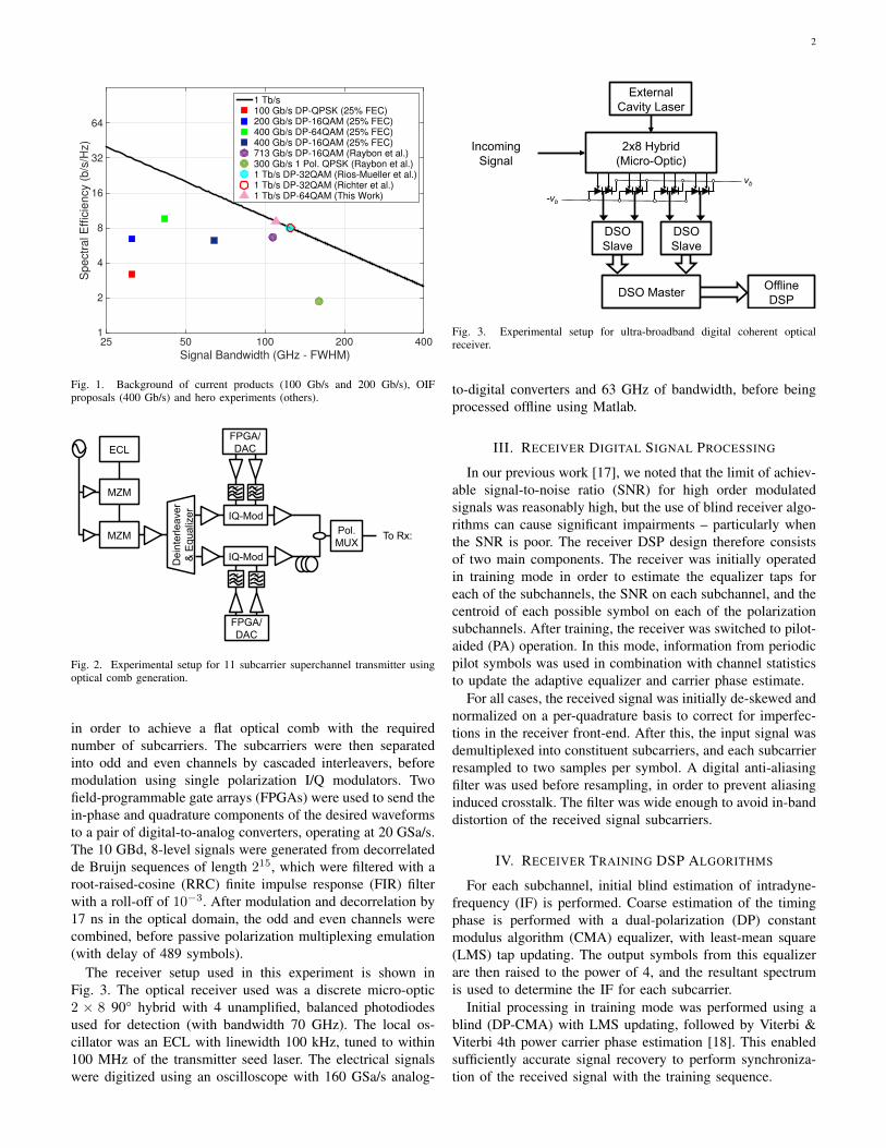
In understanding the reason for this approach to increasinginterface rates, it is useful to examine the progress of products,proposed products, and experimental records over the lastseveral years, a scatter diagram of which is plotted as SEversus bandwidth in Fig. 1. Coherent systems operating at100 Gb/s have been a technical and commercial success, relax-ing optical plant requirements while requiring only around 3×
Manuscript received October 24, 2015; revised January 1, 2016;D. S. Millar, T. Koike-Akino, M. Pajovic, K. Kojima, and K. Parsons
are with Mitsubishi Electric Research Laboratories (MERL), 201 Broadway,Cambridge, MA 02139, U.S.A. (e-mail: [email protected]; [email protected];[email protected]; [email protected]; [email protected]).
Robert Maher, Domanic Lavery, Alex Alvarado, Milen Paskov, BennC. Thomsen, and Polina Bayvel are with University College London(UCL), Torrington Place, London, U.K. (e-mail: [email protected],[email protected], [email protected], [email protected],[email protected], [email protected]).
S.J. Savory is with the University of Cambridge, Department of Engineer-ing, Electrical Division, 9 JJ Thomson Avenue, Cambridge, CB3 0FA, U.K.(email: [email protected]).
This work was in part funded by the UK EPSRC Programme GrantEP/J017582/1, and the Royal Academy of Engineering/ the Leverhulme TrustSenior Research Fellowship held by S. J. Savory.
the optical bandwidth of 10 Gb/s intensity-modulation direct-detection (IM-DD) systems. While relatively sophisticatedtransceiver optics were required for 100 Gb/s systems, theincrease in SE that they offered was enabled by the useof sophisticated digital signal processing (DSP). A furtherincrease in SE within the same bandwidth has resulted inproducts which achieve 200 Gb/s with a single carrier. Thesubsequent increase to 400 Gb/s with a single transmitter andreceiver has proven more technically challenging than mayhave initially been suspected. While real-time single carriersystems operating at 400 Gb/s have been demonstrated [9],proposed systems are currently still undergoing standardizationby the Optical Internetworking Forum (OIF) [10]. The reasonfor this is, in part, the availability of sufficiently high speedsignal convertors for the transmitter. At the time of writing,the best available arbitrary waveform generator (AWG) has32 GHz of analog bandwidth [11], while the best availablereal-time digital sampling oscilloscope has 100 GHz [12].To overcome the bandwidth limits of commercially availabletransmitter hardware, recent research has therefore focused onthe use of several transmitters with lower bandwidth and goodnoise performance to create a superchannel [13], which is thendetected by a single receiver [6]–[8], [14], while optical timedivision multiplexing has also been investigated [15].
In this paper, we develop our previous work [8] and providea thorough exposition of the detailed design of receiver DSPcapable of detecting a 1 Tb/s superchannel. In section II,we describe the experimental hardware used for generationand detection of a 1 Tb/s superchannel. We then providean overview of the receiver DSP strategy in section III,before describing the details of the receiver training algorithmsin section IV, and pilot-aided algorithms in section V. Wethen discuss the experimental performance of the varioussubsystems in section VI, before providing conclusions insection VII.
II. EXPERIMENTAL SETUP
The transmitter setup used in this experiment is shownin Fig. 2. An external cavity laser (ECL) with 100 kHzlinewidth was used to seed an optical comb generator (OCG),resulting in 11 subcarriers spaced at 10.01 GHz [16]. TheOCG consisted of two Mach–Zehnder modulators (MZMs),driven with a 10.01 GHz sinusoid. Driving amplitude and biaswere tuned along with the sinusoid phase at each modulator
2
Signal Bandwidth (GHz - FWHM)25 50 100 200 400
Spectr
al E
ffic
iency (
b/s
/Hz)
1
2
4
8
16
32
64
1 Tb/s100 Gb/s DP-QPSK (25% FEC)200 Gb/s DP-16QAM (25% FEC)400 Gb/s DP-64QAM (25% FEC)400 Gb/s DP-16QAM (25% FEC)713 Gb/s DP-16QAM (Raybon et al.)300 Gb/s 1 Pol. QPSK (Raybon et al.)1 Tb/s DP-32QAM (Rios-Mueller et al.)1 Tb/s DP-32QAM (Richter et al.)1 Tb/s DP-64QAM (This Work)
Fig. 1. Background of current products (100 Gb/s and 200 Gb/s), OIFproposals (400 Gb/s) and hero experiments (others).
MZM
Dei
nter
leav
er
& E
qual
izer
FPGA/DAC
FPGA/DAC
IQ-Mod
IQ-Mod Pol. MUX
MZM
ECL
To Rx:
Fig. 2. Experimental setup for 11 subcarrier superchannel transmitter usingoptical comb generation.
in order to achieve a flat optical comb with the requirednumber of subcarriers. The subcarriers were then separatedinto odd and even channels by cascaded interleavers, beforemodulation using single polarization I/Q modulators. Twofield-programmable gate arrays (FPGAs) were used to send thein-phase and quadrature components of the desired waveformsto a pair of digital-to-analog converters, operating at 20 GSa/s.The 10 GBd, 8-level signals were generated from decorrelatedde Bruijn sequences of length 215, which were filtered with aroot-raised-cosine (RRC) finite impulse response (FIR) filterwith a roll-off of 10−3. After modulation and decorrelation by17 ns in the optical domain, the odd and even channels werecombined, before passive polarization multiplexing emulation(with delay of 489 symbols).
The receiver setup used in this experiment is shown inFig. 3. The optical receiver used was a discrete micro-optic2 × 8 90° hybrid with 4 unamplified, balanced photodiodesused for detection (with bandwidth 70 GHz). The local os-cillator was an ECL with linewidth 100 kHz, tuned to within100 MHz of the transmitter seed laser. The electrical signalswere digitized using an oscilloscope with 160 GSa/s analog-
External Cavity Laser
Offline DSP
2x8 Hybrid (Micro-Optic)
vb
DSO Slave
DSO Slave
DSO Master
-vb
Incoming Signal
Fig. 3. Experimental setup for ultra-broadband digital coherent opticalreceiver.
to-digital converters and 63 GHz of bandwidth, before beingprocessed offline using Matlab.
III. RECEIVER DIGITAL SIGNAL PROCESSING
In our previous work [17], we noted that the limit of achiev-able signal-to-noise ratio (SNR) for high order modulatedsignals was reasonably high, but the use of blind receiver algo-rithms can cause significant impairments – particularly whenthe SNR is poor. The receiver DSP design therefore consistsof two main components. The receiver was initially operatedin training mode in order to estimate the equalizer taps foreach of the subchannels, the SNR on each subchannel, and thecentroid of each possible symbol on each of the polarizationsubchannels. After training, the receiver was switched to pilot-aided (PA) operation. In this mode, information from periodicpilot symbols was used in combination with channel statisticsto update the adaptive equalizer and carrier phase estimate.
For all cases, the received signal was initially de-skewed andnormalized on a per-quadrature basis to correct for imperfec-tions in the receiver front-end. After this, the input signal wasdemultiplexed into constituent subcarriers, and each subcarrierresampled to two samples per symbol. A digital anti-aliasingfilter was used before resampling, in order to prevent aliasinginduced crosstalk. The filter was wide enough to avoid in-banddistortion of the received signal subcarriers.
IV. RECEIVER TRAINING DSP ALGORITHMS
For each subchannel, initial blind estimation of intradyne-frequency (IF) is performed. Coarse estimation of the timingphase is performed with a dual-polarization (DP) constantmodulus algorithm (CMA) equalizer, with least-mean square(LMS) tap updating. The output symbols from this equalizerare then raised to the power of 4, and the resultant spectrumis used to determine the IF for each subcarrier.
Initial processing in training mode was performed using ablind (DP-CMA) with LMS updating, followed by Viterbi &Viterbi 4th power carrier phase estimation [18]. This enabledsufficiently accurate signal recovery to perform synchroniza-tion of the received signal with the training sequence.

3
Input Signal
Pilot-Aided RDE Pilot-Aided RDE Signal Preparation
Pilot-Aided RDE Pilot-Aided RDE Down-conv./ RRC Filt./ IF comp.
Pilot-Aided RDE
Pilot-Aided RDE
Pilot-Aided RDE
Pilot-Aided RDE
Pilot-Aided RDE Pilot-Aided RDE DP-RDE Update
Pilot-Aided RDE Pilot-Aided RDE
Pilot-Aided RDE Pilot-Aided RDE
Pilot-Aided RDE Pilot-Aided RDE
Training Sequences
Centroid Calc.
Trained CPE
Trained DP-RDE
Subcarrier DEMUX
IF Estimation
DP-CMA Equalizer
EQ Tap Initialization
Demod. Training
Fig. 4. Schematic of receiver operation in training mode.
A. Equalizer training
For each subchannel, a DP radius-directed equalizer (RDE)with LMS updating was used to equalize polarization rotationsand filtering impairments, and to recover the timing phase. Theoutput v of the equalizer at time k, for polarizations x and yis given by
vx(k) = hHxxux + hHxyuy, (1)
vy(k) = hHyxux + hHyyuy, (2)
where ux and uy are the input (column) vectors for the x andy polarizations, H denotes the Hermitian transpose, and thefour FIR filter vectors are hxx, hxy , hyx and hyy.
The equalizer was trained based on the radius of the symbolsin the training sequence. The trained equalizer error termswere calculated with the following equations:
ex(k) = |Tx(k)|2 − |vx(k)|2, ey(k) = |Ty(k)|2 − |vy(k)|2,(3)
where Tx(k) and Ty(k) are the training symbols at time k onthe x and y polarizations, respectively. This leads to the LMSupdate for the filters given by:
hxx′ = hxx + µex(k)uxv
∗x(k), (4)
hxy′ = hxy + µex(k)uyv
∗x(k), (5)
hyx′ = hyx + µey(k)uxv
∗y(k), (6)
hyy′ = hyy + µey(k)uyv
∗y(k), (7)
where the conjugation operator is denoted by ∗.By using a trained equalizer adapted only on the radius
of the received signals, we were able to attain excellentequalization of the signal with unconstrained phase. Thisenabled us to have an equalization structure which could adaptslowly in response to the slowly varying polarization channel,while phase tracking could be performed with a significantlyhigher rate of tracking.
B. Carrier phase estimation trainingCarrier phase estimation (CPE) was performed using a data-
aided feedforward algorithm, somewhat similar to the non-data-aided algorithm proposed in [19]. A phase estimate φ iscalculated at time k by multiplying the Hermitian transposeof an input vector v with the training symbol vector T, andtaking the complex argument:
φ(k) = arg(vHT). (8)
We note that this phase estimate does not require unwrap-ping, as it is already on the interval (−π, π]. The input signalv is then corrected for phase at instant k, to produce a phasecorrected output r according to:
r(k) = v(k)ejφ(k). (9)
C. Centroid calculationAfter correcting for the phase noise on the training se-
quence, we were able to calculate the centroid of each ofthe 64 constellation points, and the SNR for each of the 22polarization subchannels. For each symbol s in the set ofsymbols S, a new symbol s′ was calculated as the complexmean of the received training symbols r which correspond totransmitted training symbols t being equal to s as follows:
s′ = E(r|t = s), ∀s ∈ S, (10)
where E denotes expectation. The new set of distorted symbolsS′ were subsequently used in the pilot-aided CPE, and thecalculation of bit log-likelihood ratios (LLRs) [20].
V. PILOT-AIDED DSP ALGORITHMS
After training had led to a well converged equalizer, withaccurately calculated IF offsets and constellation centroids,the receiver was switched to pilot-aided operation, with a1% pilot-insertion ratio (PIR). A schematic of the pilot-aided receiver operation is shown in Fig. 5. The frequencysubchannels were prepared as before, with IF correction andmatched RRC filtering being performed before any pilot-aidedprocessing.

4
Input Signal
Pilot-Aided RDE Pilot-Aided RDE Signal Preparation
Pilot-Aided RDE Pilot-Aided RDE Down-conv./ RRC Filt./ IF comp.
Pilot-Aided RDE Pilot-Aided RDE DP-RDE Update
Pilot-Aided RDE Pilot-Aided RDE
Pilot-Aided RDE Pilot-Aided RDE
Pilot-Aided RDE Pilot-Aided RDE
Pilot Sequences Joint PA CPE
PA DP-RDE
Subcarrier DEMUX
EQ Tap Initialization
Demod. Training
BCH Decoder LDPC Decoder
Bit De-Interleaver Bit LLR Calc.
Output Bits
Fig. 5. Schematic of receiver operation in pilot-aided mode. Initial equalizer tap values and signal constellation centroids are learned during the receivertraining period.
Pilot Symbols - Y
Pilot Symbols - X
Σ
Σ
Hyx
Hxx
Hyy
Hxy
CMA + Av. / LMS
CMA + Av. / LMS
Input – Y
Input – X
Output – Y
Output – X
Fig. 6. Schematic of pilot-aided CMA equalizer.
A. Pilot-aided equalization
The equalizer taps previously calculated during trainingmode were used as the initial state of the pilot-aided equal-izers. A pilot-aided DP-CMA (PA-DP-CMA) algorithm wasused for each frequency subcarrier, with the error calculationbeing performed only for the pilot symbols (rather than everysymbol during training mode). A schematic of this equalizercan be seen in Fig. 6. We note again that this equalizerstructure is – like the conventional DP-RDE algorithm –immune to the effects of phase noise [21]. However, unlikethe DP-RDE, the PA-DP-CMA algorithm is immune to theeffects of noise artifacts introduced by incorrect decisions inthe equalizer.
The pilot-aided equalizer was adapted according to thefollowing equations:
ex(k) =1
10
9∑i=0
(|Px(k − 100i)|2 − |vx(k − 100i)|2
), (11)
ey(k) =1
10
9∑i=0
(|Py(k − 100i)|2 − |vy(k − 100i)|2
), (12)
where Px(k) and Py(k) are pilot symbols at time k on the xand y polarizations, respectively. This leads to the LMS updatefor the filters given by (4)–(7).
p1 p2 p3 p4n1 2 N
Fig. 7. Illustration of multi-pilot estimation with 2L = 4 pilots.
Adaptation of the equalizer was performed every 10 pilotsymbols, by averaging the error over a block of 10 pilots. Thissub-rate adaptation enabled us to further reduce the influenceof tap noise while operating with a step-size parameter ofµ = 10−4.
B. Pilot-aided carrier phase estimation
First, we describe in detail the multi-pilot-aided CPE algo-rithm which we have previously proposed [22] and experimen-tally demonstrated [23]. Then, we generalize it for joint carrierphase estimation of multiple channels when phase evolutionis correlated over several wavelength subchannels.
We assume that N information symbols are transmitted ina block and that each block starts with a pilot symbol. Toestimate phase of a symbol transmitted during the kth signalinginterval, we use L1 pilots preceding and L2 pilots followingthe considered symbol, and without loss of generality assumeL1 = L2 = L. Therefore, phases of information symbolsbelonging to the same block are estimated using the same setof pilots P = {p(1), . . . , p(L), p(L + 1), . . . , p(2L)}. Notethat a single pilot might belong to more than one set of pilots.Also note that phases of information symbols from differentblocks are estimated with the aid of different sets of pilots.For example, phases of the symbols between pilots p(2) andp(3) in Fig. 7 are estimated using pilots p(1), p(2), p(3) andp(4).
1) Phase noise model: Assuming all signal impairments butphase and additive noise have been compensated, a sampleof the received signal at discrete time k, v(k), is related to

5
Infer&phase&on&each&pilot&
Kalman&filtering&and&smoothing&
2K&pilots&
N&informa7on&symbols&pK& pK+1&
Interpola7on&between&pilots&
EM&refinement&&
Moving&average&filtering&
Es7mated&&phases&&
Fig. 8. Processing steps in our pilot-aided CPE algorithm.
the symbol transmitted in the corresponding signaling interval,s(k), as
v(k) = s(k)ejθ(k) + n(k), (13)
where θ(k) and n(k) are, respectively, the samples of a realphase noise and complex circularly symmetric additive whiteGaussian noise (AWGN). That is, n(k) ∼ CN (0, σ2
n), whileθ(k) is modeled as a Wiener process, i.e.,
θ(k)− θ(k − 1) ∼ N (0, σ2ρ), σ2
ρ = 2π∆ντs, (14)
where ∆ν is the combined linewidth of transmitter’s andreceiver’s lasers and τs is the symbol period. Since theconsecutive pilots p(ζ) and p(ζ + 1) are separated by N + 1signaling intervals (i.e., by N information symbols), we noteusing (14) that
θp(ζ+1) − θp(ζ) ∼ N (0, (N + 1)σ2ρ), (15)
where ζ = 1, . . . , 2L− 1.We frame the phase estimation problem by means of the
statistical inference with the goal to compute/approximatethe probability distribution of unknown phase θ(k), con-ditioned on the transmitted and received signals at pi-lot locations. That is, the proposed algorithm approximatesPr(θ(k)|v(k), sp(ζ), vp(ζ), ζ = 1, . . . , 2L), k = 1, . . . , N ,which is carried out through the steps outlined in Fig. 8.
2) Inference of Pilot Phases: Initially, the algorithm ap-proximates the posterior distribution Pr(θp(ζ)|sp(ζ), vp(ζ)) ofan unknown phase of pilot location p(ζ), given the correspond-ing transmitted pilot symbol sp(ζ) and received signal vp(ζ).This posterior can be, in principle, evaluated using the Bayes’rule and model (13). However, this approach does not yield aclosed form expression for the posterior distribution and wethus approximate it. Using the Laplace approximation [24],the pilot symbol phases are approximated (after few steps ofderivations which are omitted here) as
θp(ζ)|sp(ζ), vp(ζ) ∼ N (µp(ζ), σ2p(ζ)), (16)
whereµp(ζ) = arg{vp(ζ)s∗p(ζ)}, (17)
and
σ2p(ζ) =
σ2n
2|sp(ζ)vp(ζ)|. (18)
Note that the above computations are performed for each pilotin parallel.
After this initial step, we evaluated the posteriorp(θp(k)|sp(ζ), vp(ζ), ζ = 1, . . . , 2L), of the pilot p(k)’s (k =1, . . . , 2L) phase, conditioned on the knowledge of the trans-mitted symbols and received signals corresponding to allpilots from the set P . In doing so, we use the Kalman
filtering framework. Towards that end, we need to specifythe underlying linear dynamical model and observation model.The linear dynamical model is simply the Wiener phase noisemodel in (14). On the other hand, the observation model isconstructed as
ψp(ζ) = θp(ζ) + np(ζ), (19)
whereψp(ζ) = µp(ζ), (20)
andnp(ζ) ∼ N (0, σ2
p(ζ)), (21)
where µp(ζ) and σ2p(ζ) are as evaluated in (17) and (18).
Intuitively, ψp(ζ) is a noisy “observation” of an unknownphase, where np(ζ) is the observation noise.
Applying the Kalman smoother with linear dynamical (14)and observation model (19) yields
θp(ζ)|sp(1), vp(1), . . . , sp(2L), vp(2L)∼ N (νp(ζ), σ
2p(ζ)), ζ = 1, . . . , 2L, (22)
where mean νp(ζ) and variance σ2p(ζ) are evaluated using the
forward and backward pass through the model.In fact, 22 is the only step in our method which requires
sequential processing. To speed up this processing step, wecan reduce the number of pilots in the set P . In fact, ourstudy shows that for 64-QAM and for relevant phase noiseregimes, increasing the number of pilots 2L beyond 4 providesonly negligible performance gains. Also, this step requires abackward pass which stops at pilot p(L+ 1), which saves usfrom doing L steps in the backward pass (refer to (24)).
Alternatively, the processing in this step could also be donein parallel if the computational resources allow for performinginversion of a matrix of size 2L on each pilot. This is also areasonable approach since 2L = 4 already brings us to theedge of possible performance improvements for the systemsof our interest.
3) Estimation of Information Symbol Phases: In this stage,initial estimates of the information symbol phases are obtainedby interpolating between pilots symbol phases, estimated inthe previous stage. The initial phase estimates are then refinedby means of the expectation maximization (EM) method [24].
Recalling that the information symbols are between pi-lots p(L) and p(L + 1) and using Wiener process modelfor phase noise (14), it is shown that the posteriorPr(θ(k)|sp(ζ), vp(ζ), ζ = 1, . . . , 2L) is Gaussian distributedwith mean and variance dependent upon means and variancesof Gaussian posteriors corresponding to the pilots p(L) andp(L+ 1).
More precisely, it can be shown that
θ(k)|sp(1), vp(1), . . . , sp(2L), vp(2L) ∼ N (µk, σ2k), (23)
where
µ(k) =(N + 1− k)σ2
ρµp(L) + (kσ2ρ + σ2
p(L))νp(L+1)
(N + 1)σ2ρ + σ2
p(L)
, (24)
where µp(L) is the mean of the resulting distribution obtainedfrom Kalman’s forward pass corresponding to pilot p(L),
6
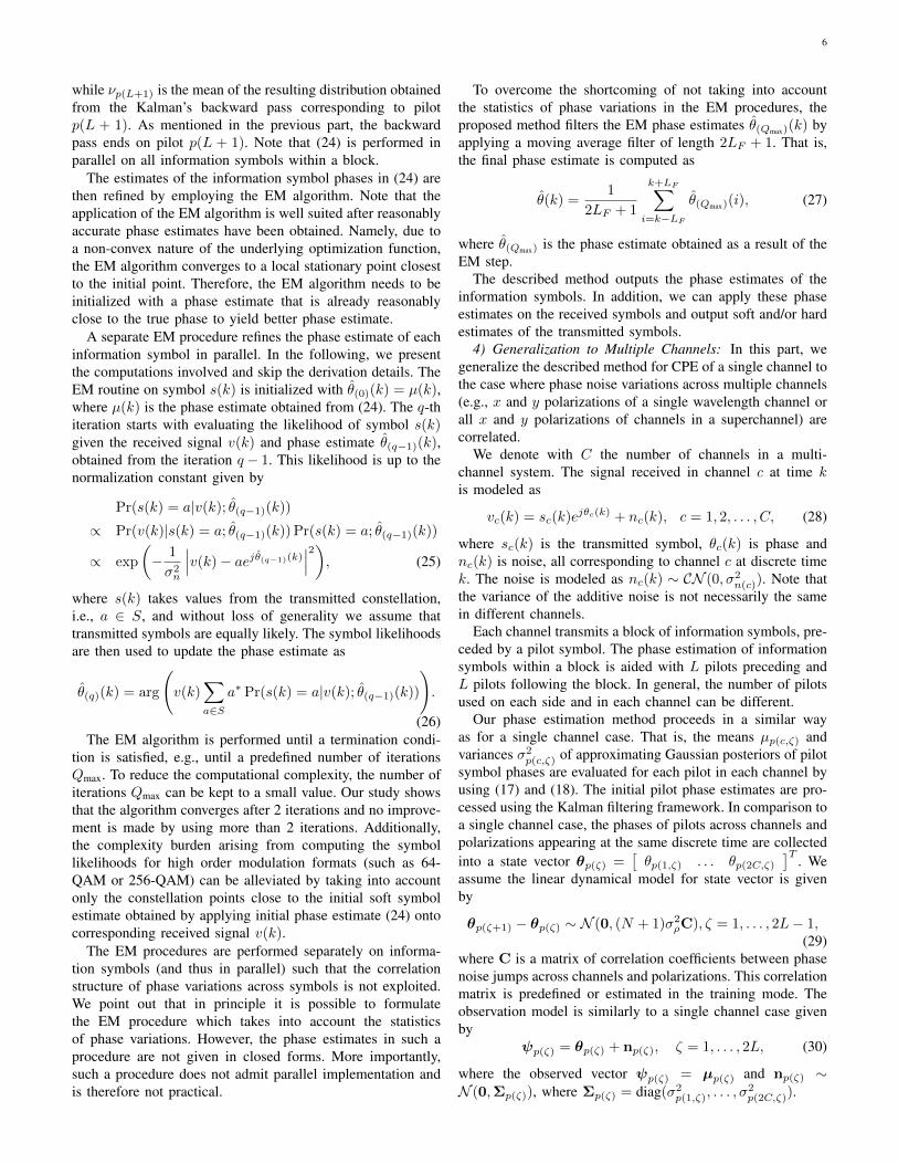
while νp(L+1) is the mean of the resulting distribution obtainedfrom the Kalman’s backward pass corresponding to pilotp(L + 1). As mentioned in the previous part, the backwardpass ends on pilot p(L + 1). Note that (24) is performed inparallel on all information symbols within a block.
The estimates of the information symbol phases in (24) arethen refined by employing the EM algorithm. Note that theapplication of the EM algorithm is well suited after reasonablyaccurate phase estimates have been obtained. Namely, due toa non-convex nature of the underlying optimization function,the EM algorithm converges to a local stationary point closestto the initial point. Therefore, the EM algorithm needs to beinitialized with a phase estimate that is already reasonablyclose to the true phase to yield better phase estimate.
A separate EM procedure refines the phase estimate of eachinformation symbol in parallel. In the following, we presentthe computations involved and skip the derivation details. TheEM routine on symbol s(k) is initialized with θ(0)(k) = µ(k),where µ(k) is the phase estimate obtained from (24). The q-thiteration starts with evaluating the likelihood of symbol s(k)given the received signal v(k) and phase estimate θ(q−1)(k),obtained from the iteration q− 1. This likelihood is up to thenormalization constant given by
Pr(s(k) = a|v(k); θ(q−1)(k))
∝ Pr(v(k)|s(k) = a; θ(q−1)(k)) Pr(s(k) = a; θ(q−1)(k))
∝ exp
(− 1
σ2n
∣∣∣v(k)− aejθ(q−1)(k)∣∣∣2), (25)
where s(k) takes values from the transmitted constellation,i.e., a ∈ S, and without loss of generality we assume thattransmitted symbols are equally likely. The symbol likelihoodsare then used to update the phase estimate as
θ(q)(k) = arg
(v(k)
∑a∈S
a∗ Pr(s(k) = a|v(k); θ(q−1)(k))
).
(26)The EM algorithm is performed until a termination condi-
tion is satisfied, e.g., until a predefined number of iterationsQmax. To reduce the computational complexity, the number ofiterations Qmax can be kept to a small value. Our study showsthat the algorithm converges after 2 iterations and no improve-ment is made by using more than 2 iterations. Additionally,the complexity burden arising from computing the symbollikelihoods for high order modulation formats (such as 64-QAM or 256-QAM) can be alleviated by taking into accountonly the constellation points close to the initial soft symbolestimate obtained by applying initial phase estimate (24) ontocorresponding received signal v(k).
The EM procedures are performed separately on informa-tion symbols (and thus in parallel) such that the correlationstructure of phase variations across symbols is not exploited.We point out that in principle it is possible to formulatethe EM procedure which takes into account the statisticsof phase variations. However, the phase estimates in such aprocedure are not given in closed forms. More importantly,such a procedure does not admit parallel implementation andis therefore not practical.
To overcome the shortcoming of not taking into accountthe statistics of phase variations in the EM procedures, theproposed method filters the EM phase estimates θ(Qmax)(k) byapplying a moving average filter of length 2LF + 1. That is,the final phase estimate is computed as
θ(k) =1
2LF + 1
k+LF∑i=k−LF
θ(Qmax)(i), (27)
where θ(Qmax) is the phase estimate obtained as a result of theEM step.
The described method outputs the phase estimates of theinformation symbols. In addition, we can apply these phaseestimates on the received symbols and output soft and/or hardestimates of the transmitted symbols.
4) Generalization to Multiple Channels: In this part, wegeneralize the described method for CPE of a single channel tothe case where phase noise variations across multiple channels(e.g., x and y polarizations of a single wavelength channel orall x and y polarizations of channels in a superchannel) arecorrelated.
We denote with C the number of channels in a multi-channel system. The signal received in channel c at time kis modeled as
vc(k) = sc(k)ejθc(k) + nc(k), c = 1, 2, . . . , C, (28)
where sc(k) is the transmitted symbol, θc(k) is phase andnc(k) is noise, all corresponding to channel c at discrete timek. The noise is modeled as nc(k) ∼ CN (0, σ2
n(c)). Note thatthe variance of the additive noise is not necessarily the samein different channels.
Each channel transmits a block of information symbols, pre-ceded by a pilot symbol. The phase estimation of informationsymbols within a block is aided with L pilots preceding andL pilots following the block. In general, the number of pilotsused on each side and in each channel can be different.
Our phase estimation method proceeds in a similar wayas for a single channel case. That is, the means µp(c,ζ) andvariances σ2
p(c,ζ) of approximating Gaussian posteriors of pilotsymbol phases are evaluated for each pilot in each channel byusing (17) and (18). The initial pilot phase estimates are pro-cessed using the Kalman filtering framework. In comparison toa single channel case, the phases of pilots across channels andpolarizations appearing at the same discrete time are collectedinto a state vector θp(ζ) =
[θp(1,ζ) . . . θp(2C,ζ)
]T. We
assume the linear dynamical model for state vector is givenby
θp(ζ+1) − θp(ζ) ∼ N (0, (N + 1)σ2ρC), ζ = 1, . . . , 2L− 1,
(29)where C is a matrix of correlation coefficients between phasenoise jumps across channels and polarizations. This correlationmatrix is predefined or estimated in the training mode. Theobservation model is similarly to a single channel case givenby
ψp(ζ) = θp(ζ) + np(ζ), ζ = 1, . . . , 2L, (30)
where the observed vector ψp(ζ) = µp(ζ) and np(ζ) ∼N (0,Σp(ζ)), where Σp(ζ) = diag(σ2
p(1,ζ), . . . , σ2p(2C,ζ)).

7
Given the linear dynamical and observation model, theproposed method processes the initial pilot phase estimatesvia full forward pass of Kalman filtering and backward passof Kalman smoothing up to pilot p(L+1). The outputs of thisprocessing stage are the mean vector µp(L) and covariancematrix Σp(L) corresponding to the pilot p(L), obtained fromthe forward pass, as well as the mean vector νp(L+1), corre-sponding to the pilot p(L + 1), resulting from the backwardpass.
Note that each step of sequential processing required in theKalman stage performs matrix inversion, where the matrix sizeis equal to 2C, i.e., all polarizations and channels. To alleviatethe computational burden, one may reduce the number of pilots2L aiding phase estimation. Our study with 64-QAM showsthat using more than 4 pilots (2 on each side) provides nofurther gains.
The second stage of the proposed method first deliversinitial estimates of information symbol phases, obtained frominterpolating between phases corresponding to pilots p(L) andp(L + 1), inferred in the previous stage. Conceptually, onecan interpolate between two Gaussian vectors (inferred phasesacross channels at locations p(L) and p(L + 1)). However,this would necessitate computing N matrix inversions (onefor each information symbol in a block). To alleviate thisshortcoming, we perform interpolation between phases in eachchannel separately. Therefore, the initial phase estimate of asymbol k in channel c is computed by
µ(c, k) =(N + 1− k)σ2
ρµp(c,L) + (kσ2ρ + σ2
p(c,L))νp(c,L+1)
(N + 1)σ2ρ + σ2
p(c,L)
,
(31)where µp(c,L) and νp(c,L+1) are the c-th entries in respectivelyµp(L) and νp(L+1), while σ2
p(r,L) is the c-th diagonal elementof Σp(L).
The initial phase estimates of information symbols arethen refined using the EM procedure as previously detailed.The EM procedure is applied to each information symbol ineach channel in parallel. The details are the same as for asingle channel case. Note that the correlations between phasesin different channels are not taken into account by runningseparate EM procedures. Conceptually, the EM procedures canbe devised so as to account for these correlations. However,this would require more complicated routines for updatingphase estimates. More specifically, a vector of phase estimatesacross channels at some discrete time would be updated as avector which minimizes the corresponding objective functionand is not given in a closed form.
The final phase estimates are obtained by filtering the EMphase estimates with the moving average filter applied ineach channel separately. The outputs from the moving averagefilter are the final phase estimates. They can be applied tothe received signal to yield soft and/or hard estimates of thetransmitted symbols.
C. Forward Error Correction CodingAfter CPE was performed, we calculated bit-wise LLRs
with the modified signal set calculated in (10). As we pre-viously noted, this method of LLR calculation allowed us to
mitigate the impact of imperfect modulation [20]. We thende-interleaved the signal over all subchannels, such that eachcodeword contained approximately equal proportions of eachof the bit-positions and subchannels. This enables the systemperformance to be determined by the average generalizedmutual information (GMI), rather than the worst subchannelor bit position [25]. Following this, we normalized the bitLLRs such that each bit was detected as though ’0’ wastransmitted. This enabled us to test a variety of LDPC codes,by decoding the all zero codeword, which exists in all linearcodes. Although we manipulated the LLR signs, no LLRvalues were changed, and the information content of the signalwas preserved.
We used a check-concentrated irregular low-density parity-check (LDPC) (105600,82368) code [26] with rate 0.78 for theinner code. LDPC decoding was performed with 60 iterationsof the sum-product algorithm, and flooding scheduling. Whilethis is a somewhat large number of iterations for an LDPCdecoder (compared with, for example, 16 iterations usedin [27]), we do not consider this to be of-itself a conditionfor high decoder complexity. Decoder complexity and latencyis discussed in detail in our work presented in [28], whereinwe analyze the effects of degree distribution, iteration count,and other topics which are beyond the scope of this work.
We assumed the use of an outer Bose–Chaudhuri–Hocquenghem (BCH) (30832,30592) code (rate 0.9922) [29]with minimum Hamming distance of 33. We have calculated aunion (upper) bound of 10−15 on the outer decoder output biterror rate (BER) given an input BER of 5× 10⁻⁵. Therefore,the input BER threshold for this outer code is at or above aninput BER of 5×10⁻⁵. Alternatively, a BER of 5×10⁻⁵ or lessat the output of the LDPC decoder can be successfully decodedto 10−15 or lower when the previously described outer BCHcode is used.
VI. RESULTS
The results presented in this section describe successfulmeasurement of a 1 Tb/s superchannel back-to-back, andwithout optical noise loading.
By training all 11 of the 2 × 2 DP-RDE equalizers inde-pendently, we are able to achieve equalization with very lowDSP penalty. We note from the taps for the central subchannel(shown in Fig. 9), that the impulse response of the channel islonger than may be expected, and 301 taps were required forgood performance. We attribute this to filtering effects fromthe receiver photodiodes and ADCs, which are operating atextremely high frequencies (more than 50 GHz).
We note from the experimental measurement shown inFig. 10, that the output phases are – as expected – highlycorrelated between polarization subchannels. We also note thatthere are varying offsets between these subchannels whichremain approximately constant. This is due to the differencein optical path lengths seen by each subchannel, includingdifferences introduced by polarization and frequency sensitivecomponents.
By examining the BER after the CPE has been performed,we noted a wide variation in performance from 8 × 10⁻³ to

8
Tap Index-100 0 100
Tap
Wei
ght
10-5
10-4
10-3
10-2
10-1
100|Hxx||Hxy||Hyx||Hyy|
Fig. 9. Absolute value of the converged equalizer taps for the centralsubchannel after the training period. Note the long response time of thesystem, necessitating a long equalizer of 301 taps.
Symbol Index ×1040 2 4 6
Rec
over
ed P
hase
(Rad
)
-25
-20
-15
-10
-5
0
5
Fig. 10. Estimated carrier phases, from multi-channel pilot-aided estimationalgorithm. Note the high degree of similarity between the estimated phases.
1.4×10⁻¹ over the different frequency subchannels (althoughperformance between different polarizations on the same fre-quency was approximately equal), in Fig. 11. We speculate thatthis variation in performance may be due to imperfect balanc-ing of the optical comb, in combination with the high loss inthe optical comb equalizer and deinterleaver. The combinationof these effects may have caused variation in the noise figureof the transmitter EDFAs over the range of frequencies in the
Subchannel Index-5 -4 -3 -2 -1 0 1 2 3 4 5
BER
10-3
10-2
10-1
100X-PolY-PolMean BER
Fig. 11. Measured bit error rate for each polarization of the 11 frequencysubchannels. Note the wide variation in performance for different frequencies.
superchannel. While it is not possible to determine the originof a source of additive noise from post-processing alone, wemay make some reasonable deductions. Due to the unevennature of both the BER and measured subchannel SNRs, andthe accurate and highly correlated recovered carrier phase, webelieve that the variation in performance is unlikely to be dueto analog electronic or DSP subsystems, while the variationin optical powers in the optical comb after deinterleaving andequalization seems to be a likely culprit for this distortion.
Despite this variation in the effective SNR over the differentsubchannels, we note that our pilot-aided CPE algorithm issufficiently robust that the phases of all subchannels are re-covered without cycle slips or significant failures in estimation.While a detailed comparison of pilot-aided and non-pilot-aidedCPE algorithms is beyond the scope of this work, we wouldlike to direct the interested reader to our previous work on thistopic in [22] and [23].
The convergence of the LDPC decoder is shown in Fig. 12.We note that despite the large variation in pre-FEC BER,convergence is still possible, and the sum-product decoder hasachieved an output below the threshold of the outer code in 47iterations, while after 55 iterations, no bit errors are detectedin any of the 74 codewords detected (∼7.8 million bits).
The union bound on input BER for a given output BER isshown in Fig. 13. By calculating a lower bound on the inputBER for a given output BER of 10−15, we have determinedthat the threshold for this code is at or above 5× 10⁻⁵.
VII. CONCLUSIONS
We have described in detail the design of a digital coherentreceiver that is capable of detecting a 1 Tb/s superchannel.The optical transmitter and receiver used in the experimentwere described in detail. Receiver training was described in

9
LDPC Decoder Iterations0 20 40 60
BER
10-6
10-5
10-4
10-3
10-2
10-1
Post-LDPCOuter BCH Code Threshold
Fig. 12. Convergence of the LDPC decoder (sum-product algorithm) forexperimental results. Mean BER is shown over 74 codewords (∼7.8 millionbits).
Input BER10-5 10-4 10-3
Out
put B
ER
10-20
10-15
10-10
10-5
BCH (30832,30592)Required Post-BCH BER
Fig. 13. Union (lower) bound on the input BER for a given output BER.BER threshold of this code is inferred to be 5× 10⁻⁵ or higher.
detail, with the aim of learning the equalizer taps, the SNRof each subchannel, and the set of constellation centroids foreach subchannel. We then described in detail the algorithmsused for pilot-aided receiver operation. A pilot-aided DP-CMAalgorithm was then described for accurate per-subchannelequalization. An extension of our previously described pilot-aided CPE was described to jointly estimate carrier phaseover several subcarriers with shared transmitter and receiverlasers. We then described the forward error correction scheme
proposed for this system, with an inner rate 0.78 LDPC codeand an outer BCH code which can correct an input BER of5 × 10−5 to an output BER of 10−15 or lower. We note thatall algorithms used in this work are of moderate complexity,and suitable for parallel implementation in hardware.
Results were then given, demonstrating operation at a netdata-rate of more than 1 Tb/s with a single digital coherentreceiver. A Nyquist-spaced coherent superchannel, consistingof 11 × 10 GBd DP-64QAM (gross bit rate of 1.32 Tb/s)was detected with an ultra-high bandwidth receiver. Pilot-aidedDSP algorithms of moderate complexity and suitable for hard-ware implementation were used, enabling robust performanceover varying subchannel SNRs with 1% pilot symbols. Aninner LDPC code and an outer BCH code were used, withcombined overhead of 29.2%, resulting in a net bit-rate of1.012 Tb/s.
REFERENCES
[1] G. Raybon et al., “All-ETDM 107-Gbaud PDM-16QAM (856-Gb/s)transmitter and coherent receiver,” in Proc. Euro. Conf. on OpticalCommun., London, UK, Sept. 2013, PD2D3.
[2] S. Beppu, K. Kasai, M. Yoshida, and M. Nakazawa, “2048 QAM (66Gbit/s) single-carrier coherent optical transmission over 150 km with apotential SE of 15.3 bit/s/Hz,” in Proc. Opt. Fiber Commun. Conf., SanFrancisco, CA, USA, Mar. 2014, W1A6.
[3] C. Zhang, Y. Mori, K. Igarashi, K. Katoh, and K. Kikuchi, “Demodulationof 1.28-Tbit/s polarization-multiplexed 16-QAM signals on a singlecarrier with digital coherent receiver,” in Proc. Opt. Fiber Commun. Conf.,San Diego, CA, USA, Mar. 2009, OTuG3.
[4] J. K. Fischer et al., “High-speed digital coherent receiver based on paralleloptical sampling,” J. Lightw. Technol., vol. 29, no. 4, pp. 378–385, 2011.
[5] N. K. Fontaine et al., “Fiber nonlinearity compensation by digitalbackpropagation of an entire 1.2-Tb/s superchannel using a full-fieldspectrally-sliced receiver,” in Proc. Euro. Conf. on Optical Commun.,London, UK, Sept. 2013, Mo3D5.
[6] R. Rios-Muller et al., “1-terabit/s net data-rate transceiver based on single-carrier Nyquist-shaped 124 GBaud PDM-32QAM,” in Proc. Opt. FiberCommun. Conf., Los Angeles, CA, USA, Mar. 2015, Th5B1.
[7] T. Richter et al., “Distributed 1-Tb/s all-optical aggregation capacity in125-GHz optical bandwidth by frequency conversion in fiber,” in Proc.Euro. Conf. on Optical Commun., London, UK, Sept. 2013, PDP.2.5.
[8] D. S. Millar et al., “Detection of a 1 Tb/s superchannel with a singlecoherent receiver,” in Proc. Euro. Conf. on Optical Commun., Valencia,ES, Sept. 2015, Mo.3.3.1.
[9] Z. Zhang et al., “Coherent transceiver operating at 61-Gbaud/s,” OpticsExpress, vol. 23, no. 15, pp.18988–18995, 2015.
[10] (2015, Jul.) ”Technology Options for 400G Implementation,” [On-line]. Available: http://www.oiforum.com/wp-content/uploads/OIF-Tech-Options-400G-01.0.pdf
[11] (2015, Oct.) Keysight M8196A Data Sheet, [Online].Available: http://literature.cdn.keysight.com/litweb/pdf/5992-0971EN.pdf?id=2631835
[12] (2015, Oct.) Teledyne LeCroy Labmaster 10Zi Data Sheet, [On-line]. Available: http://cdn.teledynelecroy.com/files/pdf/labmaster-10zi-a-datasheet.pdf
[13] G. Bosco, V. Curri, A. Carena, P. Poggiolini, and F. Forghieri, “On theperformance of Nyquist-WDM terabit superchannels based on PM-BPSK,PM-QPSK, PM-8QAM or PM-16QAM subcarriers,” J. Lightw. Technol.,vol. 29, no. 1, pp. 53–61, 2011.
[14] H. Mardoyan et al., “Transmission of single-carrier Nyquist-shaped 1-Tb/s line-rate signal over 3,000 km,” in Proc. Opt. Fiber Commun. Conf.,Los Angeles, CA, USA, Mar. 2015, W3G2.
[15] G. Raybon et al., “160-Gbaud coherent receiver based on 100-GHzbandwidth, 240-GS/s analog-to-digital conversion,” in Proc. Opt. FiberCommun. Conf., Los Angeles, CA, USA, Mar. 2015, M2G1.
[16] R. Maher et al., “Spectrally shaped DP-16QAM super-channel transmis-sion with multi-channel digital back-propagation,” Nat. Sci. Rep., vol. 5,2015, pp. 8214, 2015.
[17] D. S. Millar et al., “Transceiver-limited high spectral efficiency Nyquist-WDM systems,” in Proc. Opt. Fiber Commun. Conf., Los Angeles, CA,USA, Mar. 2015, Th2A13.

10
[18] S. J. Savory, “Digital coherent optical receivers: Algorithms and sub-systems,” IEEE J. Sel. Topics. Quantum Electron., vol. 16, no. 5, pp.1164–1179, 2010.
[19] S. Makovejs et al., “Characterization of long-haul 112Gbit/s PDM-QAM-16 transmission with and without digital nonlinearity compensa-tion,” Optics Express, vol. 18, no. 12, pp. 12939–12947, 2011.
[20] T. Koike-Akino, D. S. Millar, K. Kojima, and K. Parsons, “Phase noise-robust LLR calculation with linear/bilinear transform for LDPC-codedcoherent communications,” in Proc. Conf. on Lasers and Electro-Optics,San Jose, CA, USA, June 2015, SW1M.3.
[21] I. Fatadin, D. Ives, and S. J. Savory, “Blind equalization and carrier phaserecovery in a 16-QAM optical coherent system,” J. Lightw. Technol., vol.27, no. 15, pp. 3042–3049, 2009.
[22] M. Pajovic, D. S. Millar, T. Koike-Akino, K. Kojima, V. Arlunno, andK. Parsons, “Multi-pilot aided carrier phase estimation for single carriercoherent systems,” in Proc. Sig. Process. Photon. Commun., Boston, MA,USA, July 2015, SpT4D.4.
[23] M. Pajovic et al., “Experimental demonstration of multi-pilot aidedcarrier phase estimation for DP-64QAM and DP-256QAM,” in Proc.Euro. Conf. on Optical Commun., Valencia, ES, Sept. 2015, Mo.4.3.3.
[24] C. M. Bishop, “Pattern Recognition and Machine Learning (InformationScience and Statistics),” Springer-Verlag New York, Inc., Secaucus, NJ,USA., 2006.
[25] A. Alvarado, E. Agrell, D. Lavery, R. Maher, and P. Bayvel, “Replacingthe soft-decision FEC limit paradigm in the design of optical commu-nication systems,” J. Lightw. Technol., vol. 33, no. 20, pp. 4338–4352,2016.
[26] T. Koike-Akino, D.S. Millar, K. Kojima, and K. Parsons, “Codedmodulation design for finite-iteration decoding and high-Dimensionalmodulation,” in Proc. Opt. Fiber Commun. Conf., Los Angeles, CA, USA,Mar. 2015, W4K1.
[27] E. Yamazaki et al.,“Fast optical channel recovery in field demonstrationof 100-Gbit/s Ethernet over OTN using real-time DSP,” Optics Express,19, 2011, p. 13179.
[28] T. Koike-Akino et al., “Iteration-aware LDPC code design for low-poweroptical communications,” J. Lightw. Technol., 2016 (pre-print available).
[29] K. Sugihara et al., “A spatially-coupled type LDPC code with an NCGof 12 dB for optical transmission beyond 100 Gb/s,” in Proc. Opt. FiberCommun. Conf., Anaheim, CA, USA, Mar. 2013, OM2B4.
David S. Millar (S’07–M’11) received the M.Eng. degree in electronic andcommunications engineering from the University of Nottingham, Nottingham,U.K., in 2007, and the Ph.D. degree in Electronic and Electrical Engineeringfrom University College London (UCL), London, U.K., in 2011.
His doctoral work was concerned with the development of equalizationand modulation techniques for the mitigation of fiber nonlinearity in coherentoptical transmission systems. He is currently a Principal Member of ResearchStaff at Mitsubishi Electric Research Laboratories (MERL) in Cambridge,Massachusetts, U.S.A. His research interests include coherent optical trans-mission systems, digital coherent receiver design, coded modulation for opticalcommunications, and digital nonlinearity mitigation.
Dr. Millar has served as a Reviewer for several IEEE publications includingIEEE Photonics Technology Letters, IEEE Journal of Selected Topics inQuantum Electronics, IEEE Communications Letters, and the IEEE/OSAJournal of Lightwave Technology. He is currently serving on the TechnicalProgram Committee for the Optical Fiber Communications (OFC) Conference.
Robert Maher (M’09–SM’15) received the B.Eng. and Ph.D. degrees inelectronic engineering from Dublin City University, Dublin, Ireland, in 2005and 2009, respectively.
His doctoral research was focused on the development and characterizationof cost-efficient wavelength tunable transmitters suitable for reconfigurableagile optical networks. In 2010, he received the IRC INSPIRE Marie CurieFellowship and joined the Optical Networks Group at University CollegeLondon (UCL), London, U.K. In 2013, he was appointed as a Senior ResearchAssociate on the UNLOC EPSRC Program Grant, within the Optical NetworksGroup at UCL. His current research interests include spectrally efficient long-haul transmission for coherent optical networks, fiber nonlinearity mitigationtechniques, and dynamic optical networking.
Dr. Maher is a Member of the Marie Curie Fellows Association.
Domanic Lavery (S’09–M’13) received the M.Phys. degree in theoreticalphysics from the University of Durham, Durham, U.K., in 2009, and thePh.D. degree in electronic and electrical engineering from University CollegeLondon (UCL), London, U.K., in 2013.
His doctoral research was focused on the use of digital coherenttransceivers and their application to spectrally efficient high-capacity passiveoptical networks. He is currently with the Optical Networks Group, UCL, as aResearch Associate, investigating techniques for approaching channel capacityin nonlinear fiber transmission.
Dr. Lavery is a Member of the Optical Access Systems and WirelessBackhaul Networks subcommittee for the Optical Fiber Communication Con-ference (20152016) and was a Member of the technical programme committeefor the 20th European Conference on Networks and Optical Communications.He received the IEEE Photonics Society Graduate Student Fellowship in 2012and the Marconi Society’s Paul Baran Young Scholar Award in 2013.
Toshiaki Koike-Akino (M’05–SM’11) received the B.S. degree in electricaland electronics engineering, M.S. and Ph.D. degrees in communications andcomputer engineering from Kyoto University, Kyoto, Japan, in 2002, 2003,and 2005, respectively.
During 2006–2010, he has been a Postdoctoral Researcher at HarvardUniversity, and joined Mitsubishi Electric Research Laboratories, Cambridge,MA, USA, since 2010. His research interest includes digital signal processingfor data communications and sensing.
Dr. Koike-Akino received the YRP Encouragement Award 2005, the 21stTELECOM System Technology Award, the 2008 Ericsson Young ScientistAward, the IEEE GLOBECOM’08 Best Paper Award in Wireless Communi-cations Symposium, the 24th TELECOM System Technology EncouragementAward, and the IEEE GLOBECOM’09 Best Paper Award in Wireless Com-munications Symposium.
Milutin Pajovic (M’15) received the PhD degree in Electrical and OceanEngineering from the Massachusetts Institute of Technology and Woods HoleOceanographic Institution, in September 2014. He joined the MitsubishiElectric Research Labs (MERL) in Cambridge, MA, in September 2014,where he is currently member of the research staff. His main research interestslie in the areas of signal processing, statistical inference and machine learning,applied to physical layer optical and wireless communications and indoorlocalization.
Alex Alvarado (S’06–M’11–SM’15) was born in Quellon, on the island ofChiloe, Chile. He received his Electronics Engineer degree (Ingeniero CivilElectronico) and his M.Sc. degree (Magıster en Ciencias de la IngenierıaElectronica) from Universidad Tecnica Federico Santa Marıa, Valparaıso,Chile, in 2003 and 2005, respectively. He obtained the degree of Licentiateof Engineering (Teknologie Licentiatexamen) in 2008 and his PhD degree in2011, both of them from Chalmers University of Technology, Gothenburg,Sweden.
Dr. Alvarado is currently a Senior Research Associate at the OpticalNetworks Group, University College London, United Kingdom. In 2012–2014he was a Marie Curie Intra-European Fellow at the University of Cambridge,United Kingdom, and during 2011–2012 he was a Newton InternationalFellow at the same institution. In 2008, he was holder of the Merit ScholarshipProgram for Foreign Students, granted by the Ministere de l’Education, duLoisir et du Sports du Quebec. Dr. Alvarado is a recipient of the 2009IEEE Information Theory Workshop Best Poster Award, the 2013 IEEECommunication Theory Workshop Best Poster Award, and the 2015 IEEETransaction on Communications Exemplary Reviewer Award. His generalresearch interests are in the areas of digital communications, coding, andinformation theory.

11
Milen Paskov (S’13–M’16) received a B.Sc. degree in electrical engineeringand computer science in 2010 from Jacobs University Bremen, Germany. In2011 he received a M.Sc. in spacecraft technologies and satellite communica-tions from University College London (UCL), U.K. Between 2011 and 2015he completed his Ph.D. work within the Optical Networks Group at UCL,U.K.
His research focused on digital signal processing algorithms for coherentoptical systems and optical comb generation for optical superchannels. Afterhis Ph.D. he spent 6 months with Mitsubishi Electric Research Laboratories(MERL), Cambridge, USA working on low complexity digital signal process-ing for next generation optical systems.
Dr. Paskov is a reviewer for IEEE Photonics Technology Letters, IEEEPhotonics Journal and IEEE Transactions on Communications.
Keisuke Kojima (S’82–M’84–SM’13) was born in Hokkaido, Japan, in 1958.He received the B.S., M.S., and Ph.D. degrees in electrical engineering fromthe University of Tokyo, Tokyo, Japan, in 1981, 1983, and 1990, respectively.He also received the M.S. degree from the University of California, Berkeley,CA, USA, in 1982.
He worked for eight years at the Central Research Laboratory, MitsubishiElectric Corp., from 1983 on the research of narrow linewidth lasers andAlGaAs/GaAs DFB and DBR lasers. He spent nine years at AT&T/Lucent BellLaboratories on the R&D of uncooled Fabry–Perot and DFB lasers, vertical-cavity surface-emitting lasers, passive optical network systems, and metrooptical systems, first as a Member of Technical Staff, and later as a TechnicalManager. He also worked at Agere Systems, Denselight Semiconductors,and TriQuint Semiconductors on optical devices and modules, and opticalsystems testbed. He has been with Mitsubishi Electric Research Laboratories,Cambridge, MA, USA, since 2005, where he is currently working on theR&D of photonic-integrated circuits and coherent optical systems, as a SeniorPrincipal Member Research Staff.
Dr. Kojima has more than 160 publications in journals and conferenceproceedings, and is a Fellow of the Optical Society of America.
Kieran Parsons (M’07–SM’09) received the B.Eng. and Ph.D. degrees inelectronic and communications engineering from the University of Bristol,Bristol, U.K., in 1992 and 1996, respectively.
From 19972002, he was with Nortel Networks, Ottawa, Canada, where heworked on wireless and long-haul optical communications system architectureand design. From 2004–2006, he worked on carrier-grade mesh WiFi RF sys-tem design at BelAir Networks (now part of Ericsson) and from 2006–2009 on10-G PHY device development with Applied Micro, both in Kanata, Canada.In 2009, he joined Mitsubishi Electric Research Laboratories, Cambridge,MA, USA, where he is currently Team Leader and Senior Principal MemberResearch Staff. His research interests include digital signal processing andcoherent optical transmission systems.
Benn C. Thomsen (M’06) received the B.Tech. degree in optoelectronicsand M.Sc. and Ph.D. degrees in physics from The University of Auckland,Auckland, New Zealand.
His doctoral research involved the development and characterization ofshort optical pulse sources suitable for high-capacity optical communicationsystems. He then joined the Optoelectronics Research Centre, SouthamptonUniversity, U.K., as a Research Fellow in 2002, where he carried out researchon ultrashort optical pulse generation and characterization, optical packetswitching based on optically coded labels, and all-optical pulse processing.He joined the Optical Networks Group, University College London, London,U.K., in 2004, and held an EPSRC Advanced Fellowship from 2006 to2011 and was appointed as a lecturer in 2007. He is currently a seniorlecturer at UCL and his research focuses on optical transmission, physical-layer implementation of dynamic optical networking technology and thedevelopment of high capacity multimode fibre systems exploiting MIMO DSP.
Seb J. Savory (M’07–SM’11) received the M.Eng., M.A., and Ph.D. degreesin engineering from the University of Cambridge, U.K., in 1996, 1999, and2001, respectively, and the M.Sc. (Maths) degree in mathematics from theOpen University, Milton Keynes, U.K., in 2007.
His interest in optical communications began in 1991, when he joinedSTL (subsequently Nortel) in Harlow, U.K, Harlow. Having been sponsoredby Nortel through his undergraduate and postgraduate studies, he rejoined theHarlow Laboratories in 2000. In 2005, he moved to UCL where he held aLeverhulme Trust Early Career Fellowship from 2005 to 2007, before beingappointed as a Lecturer (2007), Reader (2012) and Professor (2015). During2014/15 he held a RAEng / Leverhulme Trust Senior Research Fellowshipand was a recipient of the RAEng Colin Campbell Mitchell Award in 2015.In October 2015 he was elected as a Fellow of Churchill College, Cambridgeand in January 2016 moved to Cambridge as a University Lecturer.
Dr. Savory is the Editor-in-Chief of IEEE Photonics Technology Lettersand serves on the Steering Committee of the Optical Fiber Communicationconference having previously served as a General Chair (2015) and ProgramChair (2013).
Polina Bayvel (S’87–M’89–SM’00–F’10) received her BSc (Eng) and PhDdegrees in Electronic & Electrical Engineering from University of London,UK, in 1986 and 1990, respectively.
In 1990, she was with the Fiber Optics Laboratory, General PhysicsInstitute, Moscow (Russian Academy of Sciences), under the Royal SocietyPostdoctoral Exchange Fellowship. She was a Principal Systems Engineerwith STC Submarine Systems, Ltd., London, UK, and Nortel Networks(Harlow, UK, and Ottawa, ON, Canada), where she was involved in the designand planning of optical fibre transmission networks. During 1994-2004, sheheld a Royal Society University Research Fellowship at University CollegeLondon (UCL), and in 2002, she became a Chair in Optical Communicationsand Networks. She is the Head of the Optical Networks Group (ONG), UCLwhich she also set up in 1994. She has authored or co-authored more than300 refereed journal and conference papers. Her research interests includewavelength-routed optical networks, high-speed optical transmission, and thestudy and mitigation of fibre nonlinearities.
Prof. Bayvel is a Fellow of the Royal Academy of Engineering (FREng),the Optical Society of America, the UK Institute of Physics, and the Instituteof Engineering and Technology. She was the recipient of the Royal SocietyWolfson Research Merit Award (2007-2012), 2013 IEEE Photonics SocietyEngineering Achievement Award, and the 2014 Royal Society Clifford Patter-son Prize Lecture and Medal. In 2015 she and 5 members of ONG receivedthe Royal Academy of Engineering Colin Campbell Mitchell Award for theirpioneering contributions to optical communications technology.