design methodology for underground ring blasting · pdf filedesign methodology for underground...
TRANSCRIPT

Design methodology for underground ringblasting
I. Onederra* and G. Chitombo
This paper discusses a systematic approach to underground ring design as well as a
methodology for the continuous improvement of designs as conditions change. The methodology
is applicable to designs for prefeasibility and feasibility stages as well as designs for currently
producing mines. The proposed method still recognises the role of experiential guidelines but
provides additional and novel empirical techniques to improve the first pass approximations such
that they better suit the prevailing geotechnical conditions. The strength of this method is that the
designer is able to assess the impact of the design in terms of the expected fragmentation and
potential damage to the surrounding rock mass.
Keywords: Blast design, Underground ring blasting, Underground mining, Underground production blasting, Fragmentation, Damage
SynopsisAs with development or tunnel blasting, undergroundring design requires an adequate understanding anddescription of the prevailing geotechnical and miningconditions; and the likely impact of the designs to theremaining rock mass. A number of published designprocesses do not always consider these importantaspects associated with ring blasting. Current practicesare generally based on either ‘rules of thumb’ orexperiential guidelines, which although useful, can onlyprovide first pass approximations at best. Over the yearsseveral modelling and simulation tools have beendeveloped to supplement the use of such rules andguidelines. More recently, numerical approaches whichlink non-ideal explosives detonation codes to geomecha-nical rock breakage models, have been developed withthe aim of modelling the complete blasting process fromfirst principles.35 Such approaches once validated offer anew opportunity for the industry to move away from thereliance on simple ‘rules of thumb’.
This paper discusses a systematic approach to under-ground ring design as well as a methodology for thecontinuous improvement of designs as conditionschange. The methodology is applicable to designs forprefeasibility and feasibility stages as well as designs forcurrently producing mines. The proposed method stillrecognises the role of experiential guidelines butprovides additional and novel empirical techniques toimprove the first pass approximations such that theybetter suit the prevailing geotechnical conditions andthus allowing for blast design optimisation. The strengthof this method is that the designer is also able to assessthe impact of the design in terms of the expectedfragmentation and potential damage to the surrounding
rock mass, provided the user has the required inputparameters for the corresponding models.
Within the context of this paper, underground ringblasting refers to long hole blasting techniques asapplied in mining methods such as bench stoping, sublevel open stoping and SLC including undercut blastingand drawbell blasting in the case of block and panelcaving methods. All of these methods have been fullydescribed in Refs. 5 and 12.
Ring design terminologyIn this paper, the following terminology is used:
(i) ring: this is a collection of blastholes in a givenplane forming what is often termed a blastholefan. Blastholes are generally drilled radially froma central location or pivot point (e.g. drillposition), although a ring may also refer to aset of parallel blastholes
(ii) ring plane: this refers to the plane in which a fanor ring of blastholes resides. It is generallydefined by a bearing (dip direction) and a dipangle (inclination). Depending on the size andgeometry of the blasted volume, a design maycontain one or more ring planes. For example insublevel caving (SLC) blasting, ring designsreside in only one plane, in contrast to largeopen stopes or drawbell blasting, several ringsmay reside in multiple oriented planes
(iii) ring dump: ring dump refers to the angle ofinclination of a ring plane. It is generally appliedin confined blasting conditions such as SLC andundercut blasting applications. The angle ofdumping ranges from 10 to 20u. There is empiricalevidence16 suggesting that dump angle may havean impact on fragmentation uniformity as thisfactor may be directly related to the degree ofconfinement or void volume available for rockdisplacement
BRC Mining and Geology, Sustainable Minerals Institute, The University ofQueensland, Brisbane, Australia
*Corresponding author, email [email protected]
180
� 2007 Institute of Materials, Minerals and MiningPublished by Maney on behalf of the InstituteReceived 4 March 2007; accepted 1 January 2008DOI 10.1179/174328607X282244 Mining Technology 2007 VOL 116 NO 4

(iv) drill position or pivot point position: this refersto the position inside a development drive wherethe pivot point of the drill rig is located. In adesign it defines the point from which the angleof blastholes is measured
(v) toe spacing: the most commonly used definitionsof toe spacing are illustrated in Fig. 1. Thedefinition adopted in the proposed methodologyis that defined as the true toe spacing ‘S’ given bythe perpendicular distance from the shortest to thelongest hole as shown by the Julius KruttschnittMineral Research Centre (JKMRC) approach
(vi) ring burden: ring burden is defined as thedistance between the ring plane and the nextfree face against which the rock volume is beingblasted. Ring burden is also referred to as thedesign burden
(vii) critical charging distance: refers to the distancebetween adjacent charges that minimises thelikelihood of explosive desensitisation or chargeinteraction. This is illustrated later in the text
(viii) standoff or offset distance: refers to the distancebetween a blasthole or toe of a blasthole and anexcavation boundary (e.g. stope or drill driveboundary)
(ix) charge length: the length (m) of explosive chargein a blasthole
(x) uncharged collar lengths: the length (m) of holeleft uncharged from the collar
(xi) toe energy concentration: toe energy concentra-tion in units of kg m23 or kg t21 refers to theconcentration of energy in the toe region of aring at a given burden. It is calculated using the3D explosive energy distribution approachproposed by Kleine15 which is discussed insubsequent sections of this paper
(xii) critical burden: the minimum burden distance atwhich no breakage and displacement occurs. Atdistances equal or greater than the criticalburden, the likelihood of freezing increases.
Proposed design methodologyThe proposed methodology follows a generic designapproach discussed also by the authors in a paperpublished by Scott et al.37 but further modified forunderground production ring blasting. As shown inFig. 2, the process effectively ‘forces’ the design engineerto follow a systematic approach to blast design by takinginto consideration factors and parameters consideredkey to successful design, implementation and optimisa-tion of ring blasting in different mining conditions. Thispaper focuses on the design and analysis process
1 Definitions of toe spacing
2 General approach to blast design
Onederra and Chitombo Design methodology for underground ring blasting
Mining Technology 2007 VOL 116 NO 4 181

highlighted in the figure. In this methodology, theapplication of accepted rules of thumb is supplementedby a 3D and 4D explosive energy distribution analysis,damage and fragmentation models and blast simu-lation tools. The process also requires identificationof risks and mitigation factors prior to implementation.The process is iterative and demonstrates the need tocontinually review implemented designs as miningconditions change. As with most design approaches,the successful application of this methodology dependson the type, quality and quantity of data used asinputs.
Definition of objectivesWhen designing a blast, the starting point should bedefining the clear objectives or requirements of that blastand they should be measurable or quantifiable. Thesemay include achieving a certain size fragmentationdistribution; minimising damage or not exceedingcertain vibration thresholds; minimising backbreak,overbreak or dilution; achieving loading and handlingproductivity targets, consistent drawpoint availabilityand efficient ore pass performance. In the case of blockcaving undercut and drawbell design, the designobjectives may reflect specific requirements which mayinclude:
(i) rapid undercutting and drawbell extraction
(ii) ease of drilling and charging of the undercutand drawbell rings while at the same timeensuring safe working conditions
(iii) ensuring complete breakage of the undercut anddrawbells by achieving suitable explosive energyconcentrations and distribution
(iv) achieving suitable fragmentation and throw forsubsequent rilling and ore handling
(v) minimising the potential of blast damage tomajor and minor apex pillars and brows.
Well defined objectives are meant to provide a clear pathforward for the definition of preliminary design para-meters and support the selection of the most appropriatemodelling tools to evaluate these parameters.
Characterisation and definition of blastingdomainsBlasting domains are zones within a mining area thathave a similar response to blasting. These can bedelineated by lithology, structure, alteration or anyother property that significantly controls blastingperformance. Domains may or may not coincide withdomains delineated for geotechnical purposes and hencethey should be jointly delineated by the geology,geotechnical and blasting departments. For under-ground ring blasting, the delineation of domains shouldinclude the following parameters which are known toinfluence blast performance and therefore results:
(i) unconfined compressive strength and tensilestrength. Both of these parameters are used asinput for the damage and fragmentation modelsin the proposed methodology
(ii) rock material and rock mass stiffness defined bysonic velocities or static and dynamic young’smodulus. These parameters are also used asinput for damage and fragmentation models
(iii) rock density. This parameter is used in the 3Dand 4D explosive energy distribution analysis,
and more specifically in calculating the energyconcentrations at the burden or ring toe sections
(iv) degree of fracturing (fracture frequency, loca-tion and orientation of major structures). Theseare used as input into the fragmentation modelsbut also qualitatively help identify criticalboundaries that may influence overbreak anddilution outcomes
(v) a general description of the in situ stress regime.This information is currently used qualitativelyas the impact of stress in the blasting process isstill not well understood. Numerical models arecurrently being developed to quantify in-situstress regimes on blast performance.35
Definition of geometry and boundary conditionsBoundary conditions include stope outlines, drillingdrive outlines and major geological features. Theseinfluence various aspects of design patterns including thedefinition of drill (pivot) positions, standoff distancesand explosive charge concentration.
Computer aided design and mine planning softwaretools provide the platforms for managing geometricaland geotechnical information. Laser based cavitymonitoring systems are now systematically used todefine adjacent stope volumes and boundaries. This isimportant for example, when designing rings againstfilled or old stopes.
Blast design essential tool kitIn terms of ring design, the key design tools that alsoinfluence the choice of the design parameters are drillingequipment, range of explosive types and initiationsystems. The design engineer needs to have a thoroughappreciation of the capabilities and limitations of eachone of these enabling technologies. The key aspects toconsider include:(i) drilling equipment
N size and shape of drilling drives
N type and capability of available drill rigs
N # range of hole diameters that the rig can drill
N # maximum hole length that can be drilledand drilling accuracy
N # alignment and drill stabilising systems
N # control systems available such as rotaryactuators and pendulum arms
N # pivot positioning constraints with respect toexcavation boundaries
N # overall drilling performance (penetrationrates and wear)
(ii) explosives, initiation systems and delivery systems
N type of explosive and critical diameter (e.g.ANFO or gassed emulsions)
N ability to vary the density of the product
N for pumpable products, the capability of thedelivery systems with respect to blastholediameter and length
N sensitivity of product in situ (e.g. sleep times anddead pressing)
N range of delays available
N accuracy of delays.At prefeasibility and feasibility stages, the blastingengineer is able to influence the specification andtherefore choice of the design tool kit, however in anoperating mine, the engineer is forced to design andoptimise blasts within the constraints of the existing or
Onederra and Chitombo Design methodology for underground ring blasting
182 Mining Technology 2007 VOL 116 NO 4

available design tool kit. Thus the importance of athorough appreciation of the capabilities of the blastdesign engineers tool kit during design and implementa-tion is essential.
Design and analysis processIn the proposed methodology, first pass parameters areinitially derived from local experience or ‘rules ofthumb’. Those often used by the authors are describedin this paper. The suitability of these parameters to theprevailing conditions is then evaluated through the static3D explosive energy distribution analysis, dynamic 4Denergy distribution analysis where appropriate; break-age uniformity analysis; fragmentation and damagemodelling; and blast visualisation and simulations.These steps and techniques are described in thefollowing sub sections.
First pass parametersA number of rules of thumb for blast design for ringblasting have been proposed over the years. The bulk ofthe rules still in use are those developed throughcontrolled tests by the US Bureau of Mines during the1970s and 80s and those developed in competentgranites by Swedish research groups. These rules havemainly been derived from correlations between singleparameters or a set of parameters such as blastholediameters, burdens and toe spacings. Such rules are site
specific and should where possible be supplemented bylocal experience. Examples of such rules for determiningblasthole diameter, design burden, toe spacing, explo-sives charging, and timing include the followings.
Blasthole diameter
In underground blasting literature, little has beenpublished with regards to ‘rules of thumb’ for determin-ing blasthole diameter; and this is often left toequipment suppliers or by evaluating the capabilitiesof the available drilling equipment. However in practice,the choice of diameter is usually influenced by themining or blasthole stoping method used, the maximumdrill length and orientation of blastholes (e.g. up holeversus down hole). Blasthole diameter may also beinfluenced by the type of explosives most likely to beused, e.g. ANFO versus bulk emulsions. Currently, forlong hole blasting, the most common diameters usedrange from 64 to 115 mm, with the most commonly useddiameters being 89 and 102 mm, particularly in up holedrilling. In such cases, these diameters can easily becharged with both ANFO and Emulsion products.Smaller diameter holes (64 or 76 mm) are generallyrestricted to activities such as drawbell blasting wherethe design objective is to minimise damage to pillars.
Design burden
For the common hole diameters used in ring blasting,design burdens typically range from 1?8 to 3?5 m andrarely 4?0 m. Available rules of thumb include:
(i) after Myers et al.;21 B53?15d (SGe/SGr)1/3 whereB is the optimal burden distance in feet, SGe isthe specific gravity of the intended explosive, SGris the specific gravity of the rock (ore) and d is thediameter of the explosive (or blasthole) in inches
(ii) after Rustan;36 where design burden is a functionof blasthole diameter d given by the followingrelation B511?8d0?63. Other relations of this kindare given in Fig. 3.
Toe spacing
The most commonly used rules for toe spacing calcula-tions are based on spacing/burden ratios (S/B) andinclude:
(i) The Julius Kruttschnitt Mineral ResearchCentre’s Experience over wide range of rockmasses defining S/B ratios in the range of 1?1 to1?4 for 76–115 mm diameter holes7,8
(ii) Rustan36 who recommends S/B ratios of 1?5 to2?0
(iii) Myers et al.21 recommend ratios in the range of1?4 to 2?0
(iv) Cunningham9 who recommends S/B ratios of1?3 to 1?5.
Explosive charging guidelines
In terms of explosives charging, the distribution ofexplosive charges within the blast volume is consideredcritical. The distribution of explosives is meant to ensureeven breakage of the blast volume, in particular at theextreme (toe) regions of a ring.
In underground production blasting, explosive den-sities are generally in the range of 0?8 to 1?2 g cc21.Guidelines generally suggest the use of higher densitiesat the toes of holes to ensure complete breakage, withreduced densities at the collar and boundary holes to
3 Comparison of blasthole diameter versus average
design burdens (after Rustan)36
Onederra and Chitombo Design methodology for underground ring blasting
Mining Technology 2007 VOL 116 NO 4 183

minimise damage to brows, pillars and the perimeter ofexcavations.
The recommended charging guidelines are sum-marised in Fig. 4. They follow the critical chargingdistance approach which is also referred to as the toespacing criteria13 and the AEL approach,9 which isbased on the definition of the shortest, intermediate andlongest uncharged collar lengths in a ring. The toespacing criteria shown in Fig. 4 is an adaptation of amethod developed and used in the Mount Isa minestopes.13 As will be discussed later, both of theseapproaches can be supplemented with the applicationof static 3D and dynamic 4D explosive energy distribu-tion analysis.
Timing guidelines
There is limited information regarding the calculation ofoptimum interhole timing for underground ring blast-ing. General published rules include interhole delays inthe range 3–15 ms m21 burden or usually ,5 ms m21
blasthole spacing. A general rule based on the ‘coopera-tion’ between adjacent charges and their potentialimpact on fragmentation is summarised in Fig. 5. Inreference to this analysis, Guest et al.10 demonstratedthat under ‘cluster blasting’ conditions or when thedelay time between holes is short or approaching zero,there is a tendency for fragmentation to become coarser
with a pronounced bimodal distribution (i.e. coarsematerials mixed with very fine materials). This is usuallyreferred to as the ‘crushing’ and ‘presplitting’ effect.Longer interhole times result in individual hole firingwith effectively no cooperation between adjacentcharges. In such cases fragmentation is assumed to bemainly structurally controlled and/or controlled by theexplosive energy. Controlled experimental work con-ducted by Stagg and Rholl40 also supports the coopera-tion time concept and the hypothetical shape of thecurve is shown in Fig. 5. As depicted in this curve, inunderground hard rock metalliferous operations, opti-mum hole cooperation in ring blasting is achieved at arange of interhole times that generally lies between 5 and25 ms.
Design evaluation processThe design evaluation process involves the applicationof analytical methods to evaluate the suitability of firstpass parameters to the prevailing mining conditions. Theanalytical tools available in this process include: thestatic 3D explosive energy distribution analysis, dynamic4D energy distribution analysis; breakage uniformityanalysis; damage modelling; fragmentation modellingand blast visualisation and simulations.
Static 3D and dynamic 4D explosive energy distribution
Kleine15 developed the concept of static 3D explosiveenergy distribution as an integration or summation ofthe energy contribution of all explosive charges at apoint in space. Calculation (energy) contours aredetermined on a defined plane, usually the ring burdenplane. The 3D energy distribution approach in itssimplest form (also referred to as 3D powder factor) islimited to calculations that only require the patterngeometry, blasthole diameter, charging quantities andthe density of the explosive and rock mass; and thus iscalculated in units of kg m23 and/or kg t21. A moredetailed description of the calculation method is given in‘Appendix’. All of the main algorithms used to calculateand display energy distribution contours have beenincorporated into the JKSimBlast design and analysissoftware described by Onederra et al.24
Figure 6 is an example of explosive energy distribu-tion contours for two similar ring patterns, using 64 and76 mm diameter holes respectively. From a designanalysis perspective, the aim is to ensure that theconcentrations at the toe sections of rings (expressed inthis case in terms of kg t21) are those that are knownthrough experience to produce acceptable breakage andfragmentation outcomes.
4 Explosive charging guidelines (toe spacing approach
and AEL approach): stemming sequence, Ts Tl Tm Tl
etc.; Ts5shortest uncharged length520 charge dia-
meters; Tm5intermediate uncharged length550 charge
diameters; Tl5longest uncharged length5125 charge
diameters; stemming not permitted to exceed two-
thirds of hole length
5 Schematic diagram of effect of interhole timing on break-
age and fragmentation in underground ring blasting
Onederra and Chitombo Design methodology for underground ring blasting
184 Mining Technology 2007 VOL 116 NO 4

An extension of this graphical analysis is shown inFig. 7, where the average toe energy concentrations arecalculated and plotted for a range of ring burdens.Results from this type of analysis allow for thecalculation of the range of practical burdens that arelikely to achieve complete breakage. In this case, thebreakage threshold was defined at the toes of rings to bein the range of 0?25 to 0?35 kg t21. As shown in thisexample, adjustments in the concentration of energy canbe made through changes in diameter (i.e. 89 mm versus102 mm) or explosive density (i.e. 1?0 g cc21 versus1?2 g cc21). The application of the 3D explosive energydistribution concept is also discussed by Guest et al.,10
Onederra et al.22 and Pierola et al.32
A noted limitation of the 3D explosive energydistribution analysis is that it does not consider theimpact of delay timing on breakage and fragmentation.A modified approach was introduced in the late ninetiesby the JKMRC,34 to address this problem. Theapproach involves the concept of ‘cooperation time’ asan index or input parameter that weights the 3Dexplosive energy contribution of each detonated chargein a blast pattern. Details of the 4D energy distributionanalysis have been made available by Riihioja34 andare also described in ‘Appendix’. It is important to notethat cooperation time has been directly associated withminimum response or burden movement time. Methodsto estimate minimum response time have been discussedby Onederra and Esen26 and Onederra.28
Energy contours derived from the dynamic 4D energydistribution analysis are akin to a ‘dynamic powderfactor’ calculation. Figure 8 shows the result of 4Denergy distribution analysis for a stope ring whereinterhole timing is varied from 25 ms, using pyrotechnicdelays, to 10 ms, using electronic delays. As shown, theenergy concentrations at both the toes and centresections of the ring are increased by allowing theexplosive charges to ‘cooperate’. In other words, the
overall dynamic powder factor for the 10 ms interholeblast is higher than for the 25 ms case. In this example,the cooperation between charges is achieved by thereduced inter hole delay (i.e. 10 ms), which is 5 ms lessthan the cooperation time (i.e. 15 ms) established forthis geometry and rock mass condition using theapproach discussed by Onederra.28 One practical andbeneficial implication of the analysis presented in thisexample is that the quantity of explosives used; and thusthe concentration of explosive charges may be reducedwhen using 10 ms interhole delays, without significantlyaffecting breakage performance.
Literature on the application of 4D analysis has beenlimited to site specific optimisation studies wheredetailed monitoring has shown that interhole timingcan have a significant effect on breakage and fragmenta-tion outcomes. An example is given by Guest et al.10 Ingeneral, the 4D energy distribution concept provides apractical graphical representation of the distribution ofenergy as a function of delay timing, and may be used as
6 Static 3D explosive energy distribution of 64 mm versus 76 mm blasthole configurations
7 Example plot of toe energy concentration versus bur-
den distance for changes in diameter and explosive
density
Onederra and Chitombo Design methodology for underground ring blasting
Mining Technology 2007 VOL 116 NO 4 185

a reference for developing empirical relations betweeninterhole timing, energy distribution and subsequentbreakage and fragmentation performance. This hasbecome particularly important with the wide spreadapplication of electronic delay detonators.
Breakage uniformity analysis
During the design process, it is important to predeter-mine the critical burden or the range of burden distancesat which the likelihood of poor breakage or possible‘freezing’ increases. A methodology based on anempirical blast damage and breakage model has beendeveloped to assist in the determination of criticalburden conditions for ring blasting. The methodologyinvolves the definition of breakage indices at a range ofdesign burdens to produce a breakage uniformity curve.The same methodology is used to determine fragmenta-tion modelling parameters.27 Figure 9 illustrates thecomponents of the breakage uniformity curve which alsodefines three practical breakage zones:
(i) the first zone is the ‘non-uniform breakage zone’which identifies burden distances in which poorbreakage and fragmentation is expected to occurand where the likelihood of freezing increases. Inthe example shown, the boundary is identified atburdens .2?3 m. In this example, this corre-sponds to spacing to burden ratios (S/B) of,1?30. Point B lies well inside this zone and canbe identified as a point in which inadequatebreakage is almost certain
(ii) the second zone is defined as the ‘transitionalzone’. It lies between the maximum attainableuniformity (point A) and the critical burdenboundary (point C). This zone identifies burdensat which breakage is expected to occur and thusprovides a way of defining a ‘practical designburden’ (i.e. point D). In the proposed approach,this is defined as the mid point between A and C.For the example shown, the practical design burdencorresponds to 1?9 m. In terms of cost savings, if
8 Example output of 4D explosive energy distribution analysis (cooperation time is equivalent to minimum response time
and was estimated with the approach proposed by Onederra)28
Onederra and Chitombo Design methodology for underground ring blasting
186 Mining Technology 2007 VOL 116 NO 4

fragmentation is not the principal design criteria,there is a clear advantage in choosing burdenswithin the region bounded by the practical designburden and the critical burden (e.g. in the range1?9–2?3 m for the 89 mm example case). However,the likelihood of poor breakage is expected toincrease as the chosen burden approaches thecritical boundary. Good quality control proceduresare essential in this zone to minimise the risk ofpoor breakage or even freezing
(iii) the third zone is the ‘uniform breakage zone’which lies to the left of the maximum attainableuniformity (point A) and identifies burdenconditions at which efficient breakage and finefragmentation is expected. In the 89 mm examplecase, this corresponds to burdens of ,1?5 m.
For a given ring design layout, the aim of the proposedapproach and the definition of these key regions is toprovide engineering approximations of the possiblerange of design burdens that would allow for effectivebreakage. The analysis takes into account rock strengthand stiffness parameters through peak particle velocity(PPV) attenuation and damage thresholds. Indices ofincipient damage and breakage are estimated fromknowledge of static tensile strength of the rock (Pa), Pwave velocity (m s21) and static Young’s modulus (Pa).
Damage modelling
Rock mass damage in underground mining can beusually associated with either a consequence of inducedstresses or blasting. Blast damage is defined asthe creation and extension of new fractures and/or theopening of pre-existing geological discontinuities in therock mass. Blast induced damage weakens a rock mass,potentially leading to stability problems when theexcavation size is increased and it is therefore animportant component of the analysis process.4
Empirical evidence from underground open stopingsuggests that near field peak particle velocity levels fromblasting can be linked to rock mass disturbance anddamage. A relationship between the critical peakvibration velocity and rock mass damage in the near
field (within a charge length) can be determined bycorrelating measured vibrations and the damage deter-mined with geotechnical instrumentation.11,2,17 Themagnitude of the vibrations depends on the nature ofthe rock mass, the blasting agent, the hole diameterused, the drilled pattern (burden, spacing, hole angle anddistance of the holes to the exposed walls) and the holedeviation. Results of back analysis work at Mount IsaMines has suggested that blasting may control up to15% of the overall stope hangingwall behaviour.44
One of the most widely used engineering methods tomodel the attenuation of blast waves in a rock mass isthe Holmberg–Persson approach.11 This approachmodels blast wave attenuation by defining two rockmass and explosive specific constants (K and a). From afundamental point of view it has however been arguedthat models which only consider contours of damage,based purely on peak vibration, may be in error ifdirectly related to stress or strain.3,30 In spite of this, theapplication of site specific damage criteria based on PPVthresholds has been well documented and supported byseveral independent studies.2,11,17–20,29,43–45 Providedthat the limitations of the adopted attenuation modelsare well understood, the above studies have demon-strated that PPV as an engineering index can still besuccessfully applied to infer the extent of damage.Table 1 provides a summary of published field workthat has been conducted to define the Holmberg–Persson attenuation constants (K and a), together withestimates of damage and breakage thresholds.
The index of incipient damage or critical peak particlevelocity PPVcrit values shown in Table 2 may beestimated from direct in situ measurements of damagesuch as those described by Villaescusa et al.45 or as a firstapproximation, by assuming the simple equation for thestress in a plane sinusoidal wave in an infinite medium31
PPVcrit~Tsvp
Est(1)
where Ts is the static tensile strength of the rock (Pa) , vp
is the compressional wave velocity (mm s21) and Est isthe static Young’s modulus (Pa).
9 Example plot of breakage uniformity curve
Onederra and Chitombo Design methodology for underground ring blasting
Mining Technology 2007 VOL 116 NO 4 187
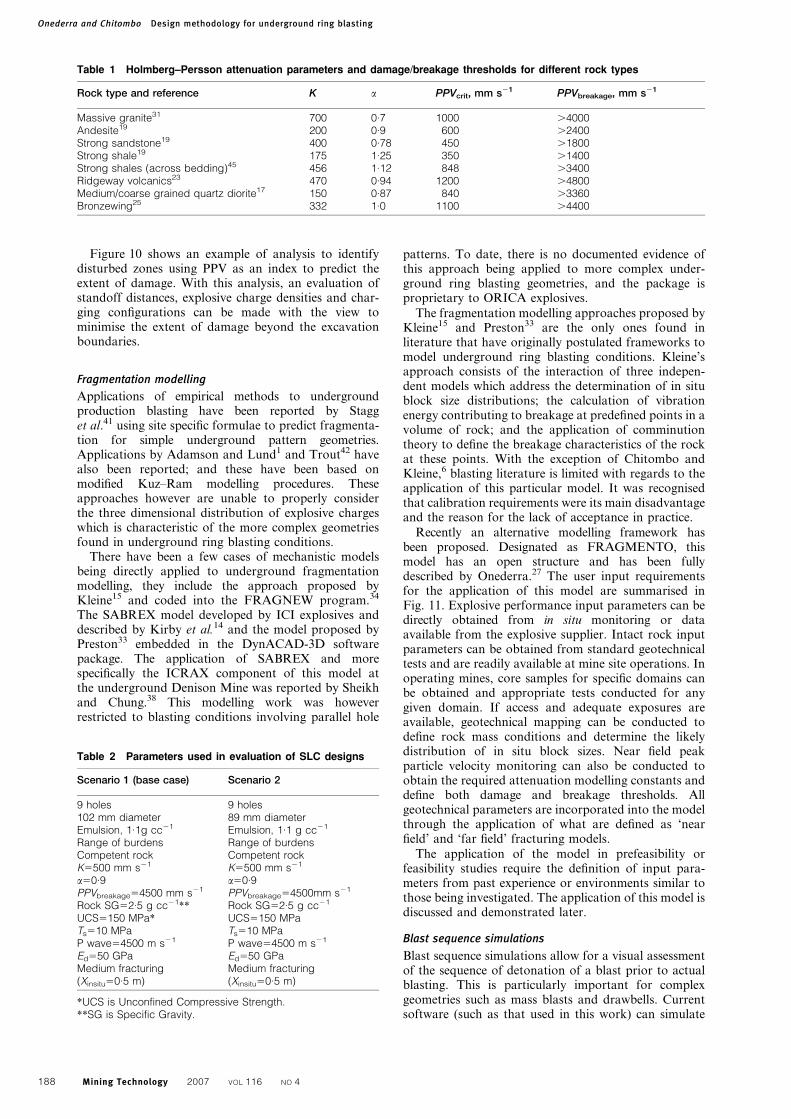
Figure 10 shows an example of analysis to identifydisturbed zones using PPV as an index to predict theextent of damage. With this analysis, an evaluation ofstandoff distances, explosive charge densities and char-ging configurations can be made with the view tominimise the extent of damage beyond the excavationboundaries.
Fragmentation modelling
Applications of empirical methods to undergroundproduction blasting have been reported by Stagget al.41 using site specific formulae to predict fragmenta-tion for simple underground pattern geometries.Applications by Adamson and Lund1 and Trout42 havealso been reported; and these have been based onmodified Kuz–Ram modelling procedures. Theseapproaches however are unable to properly considerthe three dimensional distribution of explosive chargeswhich is characteristic of the more complex geometriesfound in underground ring blasting conditions.
There have been a few cases of mechanistic modelsbeing directly applied to underground fragmentationmodelling, they include the approach proposed byKleine15 and coded into the FRAGNEW program.34
The SABREX model developed by ICI explosives anddescribed by Kirby et al.14 and the model proposed byPreston33 embedded in the DynACAD-3D softwarepackage. The application of SABREX and morespecifically the ICRAX component of this model atthe underground Denison Mine was reported by Sheikhand Chung.38 This modelling work was howeverrestricted to blasting conditions involving parallel hole
patterns. To date, there is no documented evidence ofthis approach being applied to more complex under-ground ring blasting geometries, and the package isproprietary to ORICA explosives.
The fragmentation modelling approaches proposed byKleine15 and Preston33 are the only ones found inliterature that have originally postulated frameworks tomodel underground ring blasting conditions. Kleine’sapproach consists of the interaction of three indepen-dent models which address the determination of in situblock size distributions; the calculation of vibrationenergy contributing to breakage at predefined points in avolume of rock; and the application of comminutiontheory to define the breakage characteristics of the rockat these points. With the exception of Chitombo andKleine,6 blasting literature is limited with regards to theapplication of this particular model. It was recognisedthat calibration requirements were its main disadvantageand the reason for the lack of acceptance in practice.
Recently an alternative modelling framework hasbeen proposed. Designated as FRAGMENTO, thismodel has an open structure and has been fullydescribed by Onederra.27 The user input requirementsfor the application of this model are summarised inFig. 11. Explosive performance input parameters can bedirectly obtained from in situ monitoring or dataavailable from the explosive supplier. Intact rock inputparameters can be obtained from standard geotechnicaltests and are readily available at mine site operations. Inoperating mines, core samples for specific domains canbe obtained and appropriate tests conducted for anygiven domain. If access and adequate exposures areavailable, geotechnical mapping can be conducted todefine rock mass conditions and determine the likelydistribution of in situ block sizes. Near field peakparticle velocity monitoring can also be conducted toobtain the required attenuation modelling constants anddefine both damage and breakage thresholds. Allgeotechnical parameters are incorporated into the modelthrough the application of what are defined as ‘nearfield’ and ‘far field’ fracturing models.
The application of the model in prefeasibility orfeasibility studies require the definition of input para-meters from past experience or environments similar tothose being investigated. The application of this model isdiscussed and demonstrated later.
Blast sequence simulations
Blast sequence simulations allow for a visual assessmentof the sequence of detonation of a blast prior to actualblasting. This is particularly important for complexgeometries such as mass blasts and drawbells. Currentsoftware (such as that used in this work) can simulate
Table 2 Parameters used in evaluation of SLC designs
Scenario 1 (base case) Scenario 2
9 holes 9 holes102 mm diameter 89 mm diameterEmulsion, 1.1g cc21 Emulsion, 1.1 g cc21
Range of burdens Range of burdensCompetent rock Competent rockK5500 mm s21 K5500 mm s21
a50.9 a50.9PPVbreakage54500 mm s21 PPVbreakage54500mm s21
Rock SG52.5 g cc21** Rock SG52.5 g cc21
UCS5150 MPa* UCS5150 MPaTs510 MPa Ts510 MPaP wave54500 m s21 P wave54500 m s21
Ed550 GPa Ed550 GPaMedium fracturing Medium fracturing(Xinsitu50.5 m) (Xinsitu50.5 m)
*UCS is Unconfined Compressive Strength.**SG is Specific Gravity.
Table 1 Holmberg–Persson attenuation parameters and damage/breakage thresholds for different rock types
Rock type and reference K a PPVcrit, mm s21 PPVbreakage, mm s21
Massive granite31 700 0.7 1000 .4000Andesite19 200 0.9 600 .2400Strong sandstone19 400 0.78 450 .1800Strong shale19 175 1.25 350 .1400Strong shales (across bedding)45 456 1.12 848 .3400Ridgeway volcanics23 470 0.94 1200 .4800Medium/coarse grained quartz diorite17 150 0.87 840 .3360Bronzewing25 332 1.0 1100 .4400
Onederra and Chitombo Design methodology for underground ring blasting
188 Mining Technology 2007 VOL 116 NO 4

either electronic or pyrotechnic systems. Delay scatterfactors can be assigned to pyrotechnic delays and MonteCarlo simulations run on the detonation time statisticsdefined by these factors.24
A simulation of the mass blast detonation sequenceusing pyrotechnic delays is shown in Fig. 12. In this casethe analysis had, as the main objective, the identificationof potential areas of ‘crowding’ (i.e. areas where anunacceptable number of holes detonate at the same timeor in a given time window); and the determination of theexpected explosive consumption rate (kg/unit time) as a
measure of energy release. Another example is given inFig. 13, in this case the simulation tool is used todescribe the detonation sequence of a drawbell blast.
Example applicationsThe following examples are based on actual case studies.These are meant to help illustrate the application of themethodology for ring blasting as described in theprevious sections.
10 Example of disturbed zones in drawbell blasting using PPV as index of damage
11 Input requirements of FRAGMENTO’s single ring model
Onederra and Chitombo Design methodology for underground ring blasting
Mining Technology 2007 VOL 116 NO 4 189
Case study 1: evaluation of critical burden andfragmentation outcomes of alternative SLCdesign configurationsAn existing SLC operation was interested in evaluatingring design burdens and relative changes in fragmentationas a result of changes in blasthole diameter (i.e. from 102to 89 mm). The base case design consisted of a nine holepattern and its parameters are summarised in Fig. 14.
The characteristics of the two evaluated scenarios aresummarised in Table 2.
The results of breakage uniformity analysis for thesescenarios are shown in Fig. 15. The results indicate thatfor the assumed conditions, critical design burdensshould be approximately 3?0 and 2?2 m for the 102
and 89 mm diameter configurations respectively.Practical design burdens should be of the order of2?6 m for the 102 mm configuration; and 2?0 m for the89 mm configuration.
The modelled relative changes in the expectedfragmentation for a range of burden configurations aresummarised in Fig. 16. As shown, for a given burden,relative changes in intermediate to mean fragmentationoutcomes defined by the P50 value (i.e. 50% passingfraction) are not as significant as coarse fragmentationoutcomes defined by both the P80 and P90 fractions.For the same burden (i.e. 2 m) rings drilled with 89 mmholes are expected to produce coarser fragments thanwith rings drilled with 102 mm diameter holes.
12 Example simulation of rib and crown pillar mass blast22
13 Example simulation of drawbell detonation sequence
Onederra and Chitombo Design methodology for underground ring blasting
190 Mining Technology 2007 VOL 116 NO 4

Case study 2: design parameters for narrow/inclined undercut ringsAs part of the feasibility study of a block cavingoperation, design parameters for a narrow inclinedundercut were evaluated. Figure 17 describes the para-meters for the originally proposed five hole layout. Itshould be noted that the rock mass and explosive inputparameters used in the analysis were based on thegeotechnical information available at the time andcorresponded in general terms to a ‘hard rock’ withthe characteristics summarised in Table 3.
The breakage uniformity results for the proposed fivehole ring shown in Fig. 18 indicated the critical burden
boundary to be y2?4 m, corresponding to an S/B ratioof 0?83. Burdens in the estimated transitional zoneranged from 1?8 to 2?4 m. The evaluation dictated ringburdens to be strictly ,2?4 m. Given that possibledeviations from ‘as designed’ conditions can occur inpractice, it was considered that a 1?8–2?0 m burdenconfiguration would be an adequate starting condition.In this configuration, average toe spacings were selectedafter conducting an evaluation of the three dimensionaldistribution of explosive energy for the volumes definedby the ring burdens.
14 Design parameters of base case SLC design (scenario 1)
15 Breakage uniformity analysis of 89 and 102 mm SLC
patterns16 Results of fragmentation modelling from 89 and
102 mm SLC configurations
Table 3 Mechanical and breakage properties of orebody
Rock material properties Rock mass attenuation constants and breakage threshold Rock mass structural characteristics
UCS, MPa 180 K 500Fractured Xinsitu 0.5 m
Ts, MPa 14 a 0.9vp, m s21 5300
PPVbreakage .4000 mm s21
vs, m s21 2900Ed, GPa 58Density, kg m23 2680
Onederra and Chitombo Design methodology for underground ring blasting
Mining Technology 2007 VOL 116 NO 4 191

Figure 19 shows the results of fragmentation predic-tions for the proposed five hole ring configuration.As shown, for a 2 m burden configuration, modellingresults indicated that 90% fragments are expected to be,450 mm.
During the actual extraction of the undercut and asmore data became available, the five hole inclined ringlayouts were further modified by the operation andoptimised to three hole configurations. Ring designburdens in these cases were maintained at 2?0 m andcomplete extraction of the undercut was successful.39
A back analysis of the three hole inclined ringconfiguration was conducted for the geotechnical con-ditions assumed at the feasibility stages. Figure 20shows the results of this analysis. As shown, for thethree hole configuration and the originally assumed4000 mm s21 PPV breakage threshold, critical burden
17 Design parameters of narrow inclined undercut ring
18 Breakage uniformity curve for evaluated five hole inclined undercut ring
19 Fragmentation modelling results of 89 mm inclined
undercut ring
Onederra and Chitombo Design methodology for underground ring blasting
192 Mining Technology 2007 VOL 116 NO 4
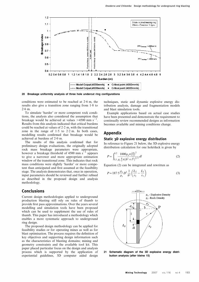
conditions were estimated to be reached at 2?6 m, theresults also give a transition zone ranging from 1?8 to2?6 m.
To simulate ‘harder’ or more competent rock condi-tions, the analysis also considered the assumption thatbreakage would be achieved at values .4500 mm s21.Results from this analysis indicated that critical burdenscould be reached at values of 2?2 m, with the transitionalzone in the range of 1?5 to 2?2 m. In both cases,modelling results confirmed that breakage would beachieved at burdens of 2?0 m.
The results of this analysis confirmed that forpreliminary design evaluations, the originally adoptedrock mass breakage parameters were appropriate,however a breakage threshold of 4500 mm s21 appearsto give a narrower and more appropriate estimationwindow of the transitional zone. This indicates that rockmass conditions were slightly ‘harder’ or more compe-tent than anticipated and first assumed at the feasibilitystage. The analysis demonstrates that, once in operation,input parameters should be reviewed and further refinedas described in the proposed design and analysismethodology.
ConclusionsCurrent design methodologies applied to undergroundproduction blasting still rely on rules of thumb toprovide first pass approximations. Over the years severalmodelling and simulation tools have been proposedwhich can be used to supplement the use of rules ofthumb. This paper has introduced a methodology whichenables a more systematic approach to undergroundring design.
The proposed design methodology can be applied forfeasibility studies or for operating mines as well as forblast optimisation. The process requires the definition ofkey objectives and supporting design information suchas the characteristics of blasting domains; mining andgeometry constraints and the available tool kit. Thispaper placed particular focus on the design and analysisprocess which is supported by the application ofexperiential guidelines, 3D computer aided design
techniques, static and dynamic explosive energy dis-tribution analysis, damage and fragmentation modelsand blast simulation tools.
Example applications based on actual case studieshave been presented and demonstrate the requirement tocontinually review recommended designs as informationbecomes available and mining conditions change.
Appendix
Static 3D explosive energy distributionIn reference to Figure 21 below, the 3D explosive energydistribution calculation for one hole/deck is given by
P~
ðL2
L1
1000rep D2
� �2
rr43
p h2zl2ð Þ2=3dl (2)
Equation (2) can be integrated and rewritten as
P~187:5re
rr
D2 1
h2
L2
r2
{L1
r1
� �(3)
20 Breakage uniformity analysis of three hole undercut ring configurations
21 Schematic diagram of the 3D explosive energy distri-
bution analysis (after kleine 15)
Onederra and Chitombo Design methodology for underground ring blasting
Mining Technology 2007 VOL 116 NO 4 193

The above calculation can be explained as anextension of the traditional powder factor calculationby writing the equation for the resulting explosiveconcentration at a point ‘P’ for a sphere centred at thecharge segment. Special conditions apply to the aboverelationships at the charge axis (i.e. h50) and at verylarge distances (i.e. h5infinity ). The explosive concen-tration at any point in 3D is determined by solving theappropriate integrated form of the equation for eachexplosive charge and summing the values. Importantpoints to note about this calculation:
(i) the result is not strictly a powder factor since asphere of rock is used. However its has beenshown that an approximation to powder factor isobtained when calculations are conducted at theburden plane
(ii) the result is a true 3D representation of theexplosive distribution.
Dynamic 4D explosive energy distributionThe 4D explosive energy distribution differs from a 3Dcalculation, in that a deck’s detonation time is con-sidered. The model is based on the 3D analysis andincorporates a weighting factor which is a function ofthe time a deck detonates and a rock mass specific factorcalled ‘cooperation time’.
As part of the 4D energy distribution analysis, atiming simulation must be carried out first in order toestimate the average detonation time of each deck. Theapproach can be used to simulate both pyrotechnic andelectronic delays. With pyrotechnic delays, a scatterfactor can be defined and Monte Carlo simulations runto simulate the potential deviation of detonation fromnominal times.
The 4D energy distribution tessellates points on aplane specified by the user just like the 3D energydistribution. For each calculation point, the nearestcharged deck is found. The time at which this deckdetonates is used as a reference time. The weightingfunction is determined based on the cooperation timeand the detonation time of charges. For every explosivedeck in the timing simulation the 3D explosive energyvalue is calculated and multiplied by the followingterm
W~e{ td{tnj j
tc
� �
where td is the time the charge deck detonated, tn is thetime the nearest deck to the calculation point detonatedand tc is the cooperation time. The graph of thisweighting function is shown in Fig. 22.
References1. W. R. Adamson and A. S. Lund: Proc. Conf. EXPLO 2001, Hunter
Valley, NSW, Australia, October 2001, The Australasian Institute
of Mining and Metallurgy, 207–223.
2. P. Andrieux, C. McKenzie, J. Heilig and A. Drolet: Proc. 10th
Symp. on ‘Explosives and blasting research’, Austin, TX, USA,
January 1994, ISEE, 107–119.
3. D. Blair and A. Minchinton: Int. J. Blast. Fragm., 1997, 2, 59–72.
4. E. T. Brown, G. P. Chitombo, T. Li and P. A. Walker: Proc. ISRM
Int. Symp. on ‘Integral approach to applied rock mechanics’, (ed.
M. van Sint Jan), Vol. I, 289–301, 1994, Santiago, ISRM.
5. E. T. Brown: ‘Block caving geomechanics’, ICS study 1997–2000,
University of Queensland, Queensland, Australia, 2003.
6. G. P. Chitombo and T. H. Kleine: Proc. 2nd Int. Symp. on ‘Rock
fragmentation by blasting’, Keystone, CO, USA, August 1987,
Society for Experimental Mechanics, 657–671.
7. G. P. Chitombo: ‘A review of the proposed front cave undercut
rings for Koffiefontein’, JKMRC/AMIRA/BART P447 report,
Brisbane, Australia, 1996.
8. G. P. Chitombo and I. Onederra: ‘Drill and blast designs and
parameters for a narrow inclined, advanced undercut of the NPM
E26 lift 2 block cave’, JKTech report no. 99257, 1999.
9. C. Cunningham: Personal communication, Documents from the
African Explosives Limited (AEL) handbook, 2005.
10. A. Guest, G. Chitombo and H. Grobler: Proc. Conf. EXPLO 1995,
Brisbane, Australia, September 1995, AusIMM, 75–80.
11. R. Holmberg and P. A. Persson: Trans. Inst Min. Metall. A, 1980,
89A, 37–40.
12. W. Hustrulid: ‘Underground mining methods: engineering funda-
mentals and international case studies’, (ed. W. A. Hustrulid and
R. L. Bullock), 3–14; 2001, Littleton, CO, Society for Mining,
Metallurgy and Exploration.
13. B. King: ‘An existing ring design program (RDS)’, Internal
JKMRC-Mining Report, Mount Isa Mines, Brisbane, Australia,
September 1987.
14. I. J. Kirby, G. H. Harries and J. P. Tidman: Proc. 13th Conf. on
‘Explosives and blasting technique’, Miami, FL, USA, February
1987, SEE, 184–194.
15. T. H. Kleine: ‘A mathematical model of rock breakage by blasting’,
PhD thesis, JKMRC-The University of Queensland, Queensland,
Australia, 1988.
16. T. Law: ‘Fragmentation analysis: determining the influence of
dump angles on fragmentation results’, Internal report, Newcrest
Mining Ltd, Ridgeway Mine, Australia, 2001.
17. T. LeBlanc, J. Heilig and J. Ryan: Proc. 6th High-Tech Semin. on
‘The state of the art in blasting technology instrumentation and
explosives applications’, Blast Analysis International Inc. and
International Society of Explosives Engineers, Boston, MA, USA,
July 1995, 225–291.
18. Q. Liu and R. Proulx: Proc. Conf. NARMS 1996: ‘Rock mechanics
tools and techniques’, 599–608; 1996, Rotterdam, Balkema.
19. C. McKenzie, C. Scherpenisse, J. Arriagada and J. Jones: Proc.
Conf. EXPLO 95, Brisbane, Australia, September 1995, AusImm,
285–292.
20. T. Meyer and P. G. Dunn: Proc. Conf. NARMS 1996: ‘Rock
mechanics tools and techniques’; Vol. 1, 609–617; 1996,
Rotterdam, Balkema.
21. T. Myers, R. Lundquist and C. Konya: Proc. 16th ISEE Annual
Conf., Orlando, FL, USA, February 1990, ISEE, 43–52.
22. I. Onederra, J. Player, P. Wade and G. Chitombo: Int. J. Blast.
Fragm., 1999, 3, 1–23.
23. I. Onederra: ‘Near field vibration monitoring of SLC ring blasting
in XC11 of the 5305 level undercut’, JKMRC-BARTII Project
Report, Newcrest Ridgeway, Ridgeway, Australia, November
2001.
24. I. Onederra, D. La Rosa, K. Riihioja and G. Power: Proc. Conf.
EXPLO 2001, Hunter Valley, Australia, October 2001, AusIMM,
237–244.
25. I. Onederra and D. La Rosa: ‘Introduction of engineering tools for
the continuous improvement of drilling and blasting practices’,
Internal JKMRC Report, Newmont-Bronzewing operation,
Australia, December 2002.
26. I. Onederra and S. Esen: Proc. EFEE 2nd World Conf. on
‘Explosives and blasting technique’, Prague, Czech Republic,
September 2003, EFEE, 269–275.
27. I. Onederra: ‘A fragmentation model for underground production
blasting;, PhD thesis, The University of Queensland, JKMRC,
Australia, 2005.
22 Weighing function of 4D analysis (After Riihioja 34)
Onederra and Chitombo Design methodology for underground ring blasting
194 Mining Technology 2007 VOL 116 NO 4

28. I. Onederra: Min. Technol. (Trans. Inst. Min. Metall. A), 2007,
116, 7–15.
29. F. Ouchterlony, C. Sjoberg and B. Jonsson: Proc. 9th Ann. Symp.
on ‘Explosives and blasting research’, San Diego, CA, USA,
January–February 1993, ISEE, 189–197.
30. F. Ouchterlony, M. Olsson and I. Bergqvist: Proc. Conf. EXPLO
2001, Hunter Valley, NSW, Australia, October 2001, AusIMM,
281–303.
31. P. A. Persson, R. Holmberg and J. Lee: ‘Rock blasting and
explosives engineering’, 259–264; 1994, Boca Raton, FL, CRC
Press.
32. M. Pierola, M. Diaz and W. Adamson: Proc. 8th Int. Symp. on
‘Rock fragmentation by blasting (Fragblast-8)’, Santiago, Chile,
May 2006, Chilean Association of Explosives Engineers, 279–289.
33. C. Preston: Proc. Conf. EXPLO 95, Brisbane, Australia, September
1995, AusIMM, 1–12.
34. K. Riihioja: Personal communication, 2004.
35. M. Ruest, P. Cundall, A. Guest and G. Chitombo: Proc. 8th Int.
Symp. on ‘Rock fragmentation by blasting (Fragblast-8)’,
Santiago, Chile, May 2006, Chilean Association of Explosives
Engineers, 140–151.
36. P. A. Rustan: Proc. 3rd Int. Symp. on ‘Rock fragmentation by
blasting (Fragblast 1990)’, Brisbane, Australia, August 1990,
AusIMM, 303–310.
37. A. Scott, I. Onederra and G. Chitombo: Proc. 8th Int. Symp. on
‘Rock fragmentation in blasting (Fragblast-8)’, Santiago, Chile,
May 2006, Chilean Association of Explosives Engineers, 232–
238
38. A. M. Sheikh and S. H. Chung: Proc. 2nd Int. Symp. on ‘Rock
fragmentation by blasting’, (ed. W. L. Fourney and R. D. Dick),
521–530; 1987, Keystone, CO, International Society of Explosives
Engineers.
39. A. Silveira: Proc. Int. Conf. MassMin 2004, Instituto de Ingenieros
de Chile, Santiago, Chile, August 2004, 410–414.
40. M. S. Stagg and S. A. Rholl: Proc. ISEE General Conf., Anaheim,
CA, February 1988, ISEE, 318–330.
41. M. S. Stagg, R. E. Otterness and F. Djahanguiri: Proc. 10th Ann.
Symp. on ‘Explosives and blasting research’, Austin, TX, USA,
January–February 1994, International Society of Explosives
Engineers, 197–208.
42. P. Trout: Proc. Underground Operators’ Conf., Townsville,
Australia, July 2002, AusIMM, 107–117.
43. A. M. Tunstall, N. Djordjevic and H. A. Villalobos: Trans. Inst.
Min. Metall. A, 1997, 106A, 42–46.
44. E. Villaescusa, C. Scott and I. Onederra: ‘Near field blast monitoring
at Hilton’, Mount Isa technical report no. RES MIN 78, 1997.
45. E. Villaescusa, I. Onederra and C. Scott: Int. J. Blast. Fragm., 2004,
8, (1), 6–29.
Onederra and Chitombo Design methodology for underground ring blasting
Mining Technology 2007 VOL 116 NO 4 195
