design method of high efficient led headlamp...
TRANSCRIPT

Design method of high-efficient
LED headlamp lens
Fei Chen,1 Kai Wang,
1 Zong Qin,
2 Dan Wu,
1 Xiaobing Luo,
3 and Sheng Liu,
1,2,*
1Division of MOEMS, Wuhan National Laboratory for Optoelectronics, School of Optoelectronic Science and Engineering, Huazhong University of Science and Technology, Wuhan 430074, China
2Institute of Microsystems, School of Mechanical Science & Engineering, Huazhong University of Science and Technology, Wuhan 430074, China
3School of Energy & Power Engineering, Huazhong University of Science & Technology, Wuhan 430074, China *[email protected]
Abstract: Low optical efficiency of light-emitting diode (LED) based headlamp is one of the most important issues to obstruct applications of LEDs in headlamp. An effective high-efficient LED headlamp freeform lens design method is introduced in this paper. A low-beam lens and a high-beam lens for LED headlamp are designed according to this method. Monte Carlo ray tracing simulation results demonstrate that the LED headlamp with these two lenses can fully comply with the ECE regulation without any other lens or reflector. Moreover, optical efficiencies of both these two lenses are more than 88% in theory.
©2010 Optical Society of America
OCIS codes: (220.2945) Illumination design; (230.3670) Light-emitting diodes; (220.4298) Nonimaging optics; (080.4225) Nonspherical lens design.
References and links
1. A. Mills, “Solid state lighting-a world of expanding opportunities at LED 2002,” III-Vs Rev. 16(1), 30–33 (2003).
2. A compilation of motor vehicle crash data from the fatality analysis reporting system, US Department pf transportation (2001).
3. T. Luce, “LED Headlamps – The Spiny Path to a Legal Headlamp,” Proc. SPIE 5663, (2005). 4. A. Cvetkovic, O. Dross, J. Chaves, P. Benitez, J. C. Miñano, and R. Mohedano, “Etendue-preserving mixing and
projection optics for high-luminance LEDs, applied to automotive headlamps,” Opt. Express 14(26), 13014–13020 (2006).
5. A. Domhardt, U. Rohlfing, and S. Weingaertner, “New design tools for LED headlamps,” Proc. SPIE 7003, (2008).
6. United Nations Economic Commission for Europe vehicle regulations, Reg. 112-Rev. 2. 7. A. Domhardt, S. Weingaertner, U. Rohlfing, and U. Lemmer, “TIR optics for non-rotationally symmetric
illumination design,” Proc. SPIE 7103, (2008). 8. J. L. Alvarez, M. Hernandez, P. Benitez, and J. C. Minano, “TIR-R Concentrator: a new compact high-gain SMS
design,” Proc. SPIE 4446, (2002). 9. F. Muñoz, P. Benı�tez, O. Dross, J. C. Miñano, and B. Parkyn, “Simultaneous multiple surface design of compact
air-gap collimators for light emitting diodes,” Opt. Eng. 43(7), 1522–1530 (2004). 10. L. W. Sun, S. Z. Jin, and S. Y. Cen, “Free-form microlens for illumination applications,” Appl. Opt. 48(29),
5520–5527 (2009). 11. K. Wang, F. Chen, Z. Y. Liu, X. B. Luo, and S. Liu, “Design of compact freeform lens for application specific
Light-Emitting Diode packaging,” Opt. Express 18(2), 413–425 (2010). 12. F. Chen, K. Wang, Z. Y. Liu, X. B. Luo, and S. Liu, “Freeform lens for application-specific LED
packaging,”Proc. International Conference on Electronic Packaging Technology & High Density Packaging (ICEPT-HDP), 443–447 (2009).
13. For data sheet of OSRAM OSTAR® headlamp LED, see http://www.osram-os.com. 14. O. Dross, R. Mohedano, P. Benitez, J. C. Minano, J. Chaves, J. Blen, M. Hernandez, and F. Munoz, “Review of
SMS methods and real word applications,” Proc. SPIE 5529, (2004).
1. Introduction
Since LEDs have many advantages over the light sources conventionally used in automotive applications, such as good reliability, energy and space savings, non fragile, environmental friendly and long life [1], LEDs were used in dashboard lighting, interior lighting and exterior signal lighting in most recent decades.
#132128 - $15.00 USD Received 22 Jul 2010; revised 26 Aug 2010; accepted 28 Aug 2010; published 12 Oct 2010(C) 2010 OSA 27 September 2010 / Vol. 18, No. 20 / OPTICS EXPRESS 20926

A research has shown that the accident rate at night is about 44% [2]. Therefore, the illumination quality of automotive lighting system is essential for safe and driving comfort. It is natural to apply LEDs in various lighting for automotives and it has been the trend that many car brands have been using LEDs now in their new models. However, LEDs are rarely applied in headlamp, which is believed to be due to two reasons: low flux of one single LED compared with conventional one single light source and low optical efficiency of optical device. If the optical efficiency of optical device is low, more LEDs are needed to comply with the regulation, which will raise the electrical power consumption of headlamp greatly. As small part of the electrical power is converted to light, headlamp will bring great heat. Usually headlamp is installed near the engine, therefore the typical ambient temperature can be about 80° [3]. If the headlamp generate large amount of heat, it will be a heavy load to cooling system. In addition, if more LEDs are used, the size and the price will also be increased. Therefore it is quite necessary to enhance the optical efficiency of optical device. Normally, there is a baffle in the projection headlamp to obtain a sharp horizontal and 15°inclined cut-off line in the measuring screen, substantial lights radiated from LEDs are kept out by the baffle, so that the optical efficiency of this type headlamp is just about 50% [3]. In recent years, as the development of non imaging optics, some LED headlamp optical design methods based on non imaging optics are suggested. Oliver Dross et al. have invented an excellent approach to designing the optical device of LED headlamp based on SMS method [4]. In their design, the optical efficiencies of both low-beam and high-beam lamp are more than 75%, which are very high values so far. In addition, Fresnel lens and micro lenses array are attempted to be used in low-beam lens design [5]. In this study, we introduce a new method of design of both low-beam and high-beam lenses, which can fully comply with the ECE regulation without any other lens or reflector. Through the numerical simulation, both of the two lenses have optical efficiencies of more than 88%.
2. Problem statement
Usually the headlamp consists of low-beam light, high-beam light and fog light. As low-beam light should give adequate illumination within safe braking distance and cannot make glare to drivers on the opposite lane, there are many restrictions for low-beam light in various regulations. Therefore the optical design of low-beam is the most difficult part. Figure 1 shows the low-beam pattern provided by ECE R112 regulation [6], which specifies the range of illuminances on specific points or segment areas and defines the minimum gradient of the cut-off line.
#132128 - $15.00 USD Received 22 Jul 2010; revised 26 Aug 2010; accepted 28 Aug 2010; published 12 Oct 2010(C) 2010 OSA 27 September 2010 / Vol. 18, No. 20 / OPTICS EXPRESS 20927

Fig. 1. Low-beam pattern on the measuring screen provided by ECE R112 Regulation
(reproduced from reference 6).
In order to avoid glare, the minimum gradient of the horizontal cut-off line is claimed in the regulation. In ECE R112 regulation, the gradient is normally defined at 2.5°to the left of v-v line by searching the maximum value G obtained by scanning the illuminance at different vertical angles β (Fig. 2), which is expressed in Eq. (1). The legal minimum value of G is 0.13.
( 0.1 )
log logG E Eβ β += −
� (1)
To obtain a beam pattern like this, a baffle is always used; however the baffle will reduce the optical efficiency greatly. At the present stage, low optical efficiency will bring a heavy load to the cooling system and LEDs account for a large part of the lamp’s total cost. Therefore, improving the lamp’s optical efficiency is very essential. In this paper, we present a new method of designing the low-beam and high-beam LED lenses.
Fig. 2. Sketch diagram of gradient of the horizontal cut-off line.
#132128 - $15.00 USD Received 22 Jul 2010; revised 26 Aug 2010; accepted 28 Aug 2010; published 12 Oct 2010(C) 2010 OSA 27 September 2010 / Vol. 18, No. 20 / OPTICS EXPRESS 20928

3. Design method
In our design, lens is separated into two parts: collection optics and refraction optics (shown in Fig. 3). The collection optics is used to collimate the lights radiated from LED; the refraction optics is used to redirect the collimated rays to obtain a regulation met beam pattern.
Fig. 3. Sketch diagram of lens’ structure.
3.1 Design of collection optics
Collection optics is used to collimate lights radiated from LED. There are two main methods to collimate rays: total internal reflection (TIR) lens and total internal reflection-refraction lens (TIR-R lens or Fresnel lens). TIR lens works well when the light source can be regarded as a point source, but if the source has a finite size, rays cannot be collimated accurately. However, the Fresnel lens structure can meet the properties of an extended light source like a 1mm × 1mm LED chip [7]. The Fresnel lens consists of two parts: inner surface and outer surface, which are shown in Fig. 3.
The Cartesian oval mathod is always used to design lens for concentrating or collimating lights [8,9]. In this design, we use Cartesian oval mathod to calculate the inner surface which is constructed in following steps. First of all, as shown is Fig. 4, we fix a point as the vertex of
the surface’s curve which is the first point ( 1
iP ) on inner surface, and the normal vector of this
point is also determined to be vertical up. The second point on the curve can be determined by the intersection of incident ray and the tangent plane of the previous point. Secondly, as the exit ray is vertical up, we calculate the present point’s normal vector by incident ray and exit ray using the inverse procedure of Snell’s law, which is expressed in Eq. (2),
1
2 2[1 2 ( )]n n n+ − = −O I N O I�� � �� �� �
i (2)
where I�
and O��
are the unit vectors of incident and refracted rays, N��
is the unit normal
vector on the refracted point, and n is the index of refraction in the lens. Finally, we can get all the points and their normal vectors on the inner surface’s curve in this chain of calculation. Then we fit these points to form the curve and rotate this curve to get the inner surface.
#132128 - $15.00 USD Received 22 Jul 2010; revised 26 Aug 2010; accepted 28 Aug 2010; published 12 Oct 2010(C) 2010 OSA 27 September 2010 / Vol. 18, No. 20 / OPTICS EXPRESS 20929

Fig. 4. Calculation of the points on the inner surface’s curve.
The outer surface uses the rays’ TIR to collimate the incident rays. Incident rays are refracted first by the vertical cylinder surface and then reflected vertically by TIR on the reflection surface which is shown in Fig. 3. For outer surface, we just need to calculate the points on curve of the reflection surface. The calculation procedure is specified as follows.
Firstly, we fix a point as the first point 1
TP of the curve and then calculate the normal vector of
this point according to the vertical exit ray and the inverse procedure of Snell’s law. Secondly, the second point on the curve can be determined by the intersection of incident ray which is refracted by the cylinder surface, and the tangent plane of the previous point. Thirdly, we use the inverse procedure of Snell’s law again to calculate the normal vector of the second point. Therefore, we can obtain all the points on the curve in the same manner, and then the reflection surface is obtained. The calculation procedure is denoted in Fig. 5.
#132128 - $15.00 USD Received 22 Jul 2010; revised 26 Aug 2010; accepted 28 Aug 2010; published 12 Oct 2010(C) 2010 OSA 27 September 2010 / Vol. 18, No. 20 / OPTICS EXPRESS 20930

Fig. 5. Calculation of the points on the TIR surface’s curve.
We design the collection optics using the method mentioned above. The collection optics collected the lights with a range of 0°to 80°, lights in which take up about 97% of the whole lights radiated by LED.
3.2 Design of refraction optics
Freeform micro lensesare sometimes used as the refraction optics in illumination optical design [5,10]. In reference 5, micro lenses array is also used to design the low-beam lens, but the lens cannot fully comply with the ECE regulation and the optical efficiency is not quite high (70%). The main disadvantage of freeform micro lenses array is that high-precision machining is needed to fabricate the microsurfaces. In this paper, we use several freeform surfaces to construct the refraction optics. The procedure of designing the freeform surface consists of meshing of target plane and calculations of the points on the surface.
3.2.1 Meshing of target plane
As the beam pattern of headlamp can be regarded as a non-uniform rectangular pattern or be resolved into several non-uniform rectangular patterns such as low-beam light pattern, freeform surface also has a rectangular appearance. In this paper, we can obtain a non-uniform beam pattern by making each incident ray intersecting at different point on the target plane, which is shown in Fig. 6. Assume there are M × N rays refracted by a freeform surface.
#132128 - $15.00 USD Received 22 Jul 2010; revised 26 Aug 2010; accepted 28 Aug 2010; published 12 Oct 2010(C) 2010 OSA 27 September 2010 / Vol. 18, No. 20 / OPTICS EXPRESS 20931
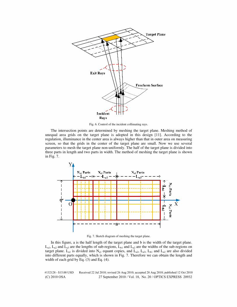
Fig. 6. Control of the incident collimating rays.
The intersection points are determined by meshing the target plane. Meshing method of unequal area grids on the target plane is adopted in this design [11]. According to the regulation, illuminance in the center area is always higher than that in outer area on measuring screen, so that the grids in the center of the target plane are small. Now we use several parameters to mesh the target plane non-uniformly. The half of the target plane is divided into three parts in length and two parts in width. The method of meshing the target plane is shown in Fig. 7.
Fig. 7. Sketch diagram of meshing the target plane.
In this figure, a is the half length of the target plane and b is the width of the target plane. La1, La2 and La3 are the lengths of sub-regions, Lb1 and La2 are the widths of the sub-regions on target plane. La1 is divided into Na1 equant copies, and La2, La3, Lb1 and La2 are also divided into different parts equally, which is shown in Fig. 7. Therefore we can obtain the length and width of each grid by Eq. (3) and Eq. (4).
#132128 - $15.00 USD Received 22 Jul 2010; revised 26 Aug 2010; accepted 28 Aug 2010; published 12 Oct 2010(C) 2010 OSA 27 September 2010 / Vol. 18, No. 20 / OPTICS EXPRESS 20932

1 1 1
2 2 2
3 3 3
a a
a a
a a
a N L
a N L
a N L
× =
× = × =
(3)
1 1 1
2 2 2
b b
b b
b N L
b N L
× =
× = (4)
In the same way, we can mesh the other half of the target plane. Through optimizing these parameters mentioned above, we can design a rectangular beam pattern needed for headlamp.
3.2.2 Calculation of freeform surface
The freeform surface is constructed by lofting with a large number of curves on the surface. We have used the seed curve iteration method to design a freeform LED packaging lens [12] in our earlier stage work. In this study, this method is used again to calculate the freeform surface. The procedure of calculation is shown in Fig. 8.
Fig. 8. Calculation of the freeform surface.
4. Designing cases
In this paper, we have designed a low-beam lens and a high-beam lens using the method introduced above. To validate our design, OSRAM OSTAR
® headlamp LED is used in the
numerical simulation. According to the data sheet of this LED, its flux can reach to 224lm when LED is driven at a specified current of 700mA [13]. We assume the flux of each LED is 200lm in the simulation. The material used in the design of both low-beam and high-beam lens is PMMA, refractive index of which is 1.493.
4.1 Design of low-beam lens
As a 15°inclined cut-off line is demanded for low-beam light pattern in regulation, the refraction optics is divided into two parts. The first part generates the horizontal beam pattern, and the second part is used to generate a 15°inclined beam pattern, therefore a regulation met beam pattern can be obtained by overlapping the two parts’ beam patterns. In our design, the first part consists of a large freeform surface and the second part is made up of 6 same freeform surfaces. The included angle of the two parts is 15°. Although the second part is
#132128 - $15.00 USD Received 22 Jul 2010; revised 26 Aug 2010; accepted 28 Aug 2010; published 12 Oct 2010(C) 2010 OSA 27 September 2010 / Vol. 18, No. 20 / OPTICS EXPRESS 20933

excised in the center area and border, the beam pattern of this part can still be accepted as the overlap effect of the 6 freeform surfaces. The diameter of low-beam lens is 78.9mm and the thickness is 26.52mm. Figure 9 shows the low-beam lens.
Fig. 9. Cross section of the low-beam lens and LED.
Through the Monte-Carlo ray tracing method based numerical simulation; we can simulate the illuminance distribution on the measuring screen. Figure 10 shows the simulated beam pattern on the measuring screen and the vertical sectional curve.
Fig. 10. (a)Simulated illuminance distribution on the measuring screen, (b) vertical sectional curve.
In the simulation, flux of light source is 400lm. Therefore, 2 LEDs and 2 low-beam lenses are used for low-beam light, which are shown in Fig. 11. The simulation result shows the optical efficiency of the low-beam is 88% (Fresnel losses included) and the maximum value
#132128 - $15.00 USD Received 22 Jul 2010; revised 26 Aug 2010; accepted 28 Aug 2010; published 12 Oct 2010(C) 2010 OSA 27 September 2010 / Vol. 18, No. 20 / OPTICS EXPRESS 20934

of G is 0.35. The optical efficiency in this study is defined as the ratio of flux into the 20 × 10 m
2 area on measuring screen to the flux of LED.
Fig. 11. (a)Low-beam lens, (b)Schematic view of low-beam light.
The comparison of simulated illumination and required illumination in lux for ECE R112 regulation is shown in Table 1, which indicates the optical performance of the low-beam lens can fully comply with the ECE regulation.
Table 1. Simulated illumination result compared with the corresponding value of ECE R112 (Class B) for low-beam light
Point on measuring screen Required illumination in lux Simulated illumination in lux
Point B50L ≤≤≤≤0.4 0.02
Point 75R ≥≥≥≥12 26.11
Point 75L ≤≤≤≤12 1.64
Point 50L ≤≤≤≤15 6.18
Point 50R ≥≥≥≥12 49.72
Point 50V ≥≥≥≥6 27.27
Point 25L ≥≥≥≥2 7.48
Point 25R ≥≥≥≥2 14.75
Any point in ZONE I ≤≤≤≤2·E* √√√√
Any point in ZONE III ≤≤≤≤0.7 √√√√ Any point in ZONE IV ≥≥≥≥3 √√√√
E* is the actually measured value in point 50R
As the regulation for low-beam light has strict restrictions, we have considered the splitting of lights at the air-PMMA interface by using the Fresnel formulae during the ray trace of above simulation. Compared with the simulation, in which the splitting of lights is not considered, the optical efficiency decreases from 94% to 88%. The cut-off line is blurred and illuminance at point 75R decreases from 35.23 lux to 26.11 lux when splitting of lights is considered.
Another issue we must consider is the effect of the rounded edges of the lens facet to the optical performance of lens. Reference 14 has discussed the effect of the teeth radii of the Fresnel lens to the optical efficiency [14]. Therefore, we have also simulated the low-beam with rounded edges. In this simulation, the radii of the edges or corners on the refraction optics are 0.3mm, the tooth radii of the Fresnel lens are set as 0.05mm, and also the splitting of lights is considered during the raytrace. Figure 12 shows rounded edges of the low-beam lens.
#132128 - $15.00 USD Received 22 Jul 2010; revised 26 Aug 2010; accepted 28 Aug 2010; published 12 Oct 2010(C) 2010 OSA 27 September 2010 / Vol. 18, No. 20 / OPTICS EXPRESS 20935

Fig. 12. Radii of the rounded edges of the low-beam lens facets.
The simulated beam pattern of low-beam lens with rounded edges is shown in Fig. 13.
Fig. 13. Simulated beam pattern of low-beam lens with rounded edges.
Figure 13 shows that disordered lights appear on the measuring screen and the max illuminance is decreased by 7.4%. The comparison of simulated illumination of low-beam lens with rounded edges considered and required illumination in lux for ECE R112 regulation
#132128 - $15.00 USD Received 22 Jul 2010; revised 26 Aug 2010; accepted 28 Aug 2010; published 12 Oct 2010(C) 2010 OSA 27 September 2010 / Vol. 18, No. 20 / OPTICS EXPRESS 20936

is shown in Table 2. From the simulation, low-beam lens with rounded edges has an optical efficiency of 79%, and the illuminaon on measuring screen is lower than the case in which the edges of low-beam lens are not rounded. However, low-beam lens with rounded edges shown in Fig. 12 can still comply with the regulation.
Table 2. Simulated illumination result compared with the corresponding value of ECE R112 (Class B) for low-beam light
Point on measuring screen Required illumination in lux Simulated illumination in lux
Point B50L ≤≤≤≤0.4 0.04
Point 75R ≥≥≥≥12 23.24
Point 75L ≤≤≤≤12 1.37
Point 50L ≤≤≤≤15 5.49
Point 50R ≥≥≥≥12 45.10
Point 50V ≥≥≥≥6 24.30
Point 25L ≥≥≥≥2 12.20
Point 25R ≥≥≥≥2 13.08
Any point in ZONE I ≤≤≤≤2·E* √√√√
Any point in ZONE III ≤≤≤≤0.7 √√√√ Any point in ZONE IV ≥≥≥≥3 √√√√
E* is the actually measured value in point 50R
4.2 Design of high-beam lens
As loose restraints of high-beam in ECE R112 regulation, size of the lens can be smaller than low-beam lens. In this design, the refraction optics is also divided into 2 parts. The center area of the refraction optics is a freeform surface and the outer part is flat surface. Diameter and thickness of high-beam lens are 25mm and 6.9mm. Figure 14 shows the high-beam lens and simulated beam pattern on measuring screen correspondingly. The optical efficiency of the high-beam lens is as high as 92% (Fresnel losses included).
Fig. 14. (a) High-beam lens, (b) simulated beam pattern of high-beam lens on measuring screen.
The simulated illuminance on measuring screen is listed in Table 3, and the flux of light source is 600lm. Therefore, 3 LEDs are needed in high-beam light.
Table 3. Simulated illumination result compared with the corresponding value of ECE R112 (Class B) for high-beam light
Point on measuring screen Required illumination in lux Simulated illumination in lux
Emax ≥≥≥≥48&≤≤≤≤240 55.1
Point HV ≥≥≥≥0.8 Emax 51.2
Point HV to 1125L and R ≥≥≥≥24 ≥≥≥≥33.3
Point HV to 2250L and R ≥≥≥≥6 ≥≥≥≥28.7
#132128 - $15.00 USD Received 22 Jul 2010; revised 26 Aug 2010; accepted 28 Aug 2010; published 12 Oct 2010(C) 2010 OSA 27 September 2010 / Vol. 18, No. 20 / OPTICS EXPRESS 20937

The simulation result indicates the optical property of the high-beam lens can also fully comply with the regulation.
5. Conclusions
In this study, a high-efficient LED headlamp lens design method is presented. There are abundant parameters to optimize the illuminance distributed on the measuring screen. Using this method, the optical lens of both low-beam and high-beam light can be designed. Through numerical simulation, headlamp with these lenses can fully comply with the ECE regulation without any other lens or reflector. And simulation result shows the two lenses have optical efficiencies more than 88% in theory. However it will take quite a long time to optimize all the parameters, we hope to solve this problem in future work by let the optimization done by computer automatically to shorten the design cycle.
Acknowledgments
This work was supported by the Nature Science Foundation of China (NSFC) Key Project under grant number 50835005.
#132128 - $15.00 USD Received 22 Jul 2010; revised 26 Aug 2010; accepted 28 Aug 2010; published 12 Oct 2010(C) 2010 OSA 27 September 2010 / Vol. 18, No. 20 / OPTICS EXPRESS 20938